EP3825753A1 - Corrective optical system and optical correction method - Google Patents
Corrective optical system and optical correction method Download PDFInfo
- Publication number
- EP3825753A1 EP3825753A1 EP19884564.6A EP19884564A EP3825753A1 EP 3825753 A1 EP3825753 A1 EP 3825753A1 EP 19884564 A EP19884564 A EP 19884564A EP 3825753 A1 EP3825753 A1 EP 3825753A1
- Authority
- EP
- European Patent Office
- Prior art keywords
- wavefront
- light
- optical compensation
- compensation system
- target
- Prior art date
- Legal status (The legal status is an assumption and is not a legal conclusion. Google has not performed a legal analysis and makes no representation as to the accuracy of the status listed.)
- Pending
Links
Images


Classifications
-
- G—PHYSICS
- G02—OPTICS
- G02B—OPTICAL ELEMENTS, SYSTEMS OR APPARATUS
- G02B27/00—Optical systems or apparatus not provided for by any of the groups G02B1/00 - G02B26/00, G02B30/00
- G02B27/0025—Optical systems or apparatus not provided for by any of the groups G02B1/00 - G02B26/00, G02B30/00 for optical correction, e.g. distorsion, aberration
- G02B27/0068—Optical systems or apparatus not provided for by any of the groups G02B1/00 - G02B26/00, G02B30/00 for optical correction, e.g. distorsion, aberration having means for controlling the degree of correction, e.g. using phase modulators, movable elements
-
- G—PHYSICS
- G02—OPTICS
- G02B—OPTICAL ELEMENTS, SYSTEMS OR APPARATUS
- G02B26/00—Optical devices or arrangements for the control of light using movable or deformable optical elements
-
- G—PHYSICS
- G01—MEASURING; TESTING
- G01S—RADIO DIRECTION-FINDING; RADIO NAVIGATION; DETERMINING DISTANCE OR VELOCITY BY USE OF RADIO WAVES; LOCATING OR PRESENCE-DETECTING BY USE OF THE REFLECTION OR RERADIATION OF RADIO WAVES; ANALOGOUS ARRANGEMENTS USING OTHER WAVES
- G01S17/00—Systems using the reflection or reradiation of electromagnetic waves other than radio waves, e.g. lidar systems
- G01S17/88—Lidar systems specially adapted for specific applications
- G01S17/95—Lidar systems specially adapted for specific applications for meteorological use
-
- G—PHYSICS
- G02—OPTICS
- G02B—OPTICAL ELEMENTS, SYSTEMS OR APPARATUS
- G02B23/00—Telescopes, e.g. binoculars; Periscopes; Instruments for viewing the inside of hollow bodies; Viewfinders; Optical aiming or sighting devices
- G02B23/24—Instruments or systems for viewing the inside of hollow bodies, e.g. fibrescopes
-
- G—PHYSICS
- G02—OPTICS
- G02B—OPTICAL ELEMENTS, SYSTEMS OR APPARATUS
- G02B26/00—Optical devices or arrangements for the control of light using movable or deformable optical elements
- G02B26/06—Optical devices or arrangements for the control of light using movable or deformable optical elements for controlling the phase of light
-
- G—PHYSICS
- G01—MEASURING; TESTING
- G01J—MEASUREMENT OF INTENSITY, VELOCITY, SPECTRAL CONTENT, POLARISATION, PHASE OR PULSE CHARACTERISTICS OF INFRARED, VISIBLE OR ULTRAVIOLET LIGHT; COLORIMETRY; RADIATION PYROMETRY
- G01J9/00—Measuring optical phase difference; Determining degree of coherence; Measuring optical wavelength
-
- Y—GENERAL TAGGING OF NEW TECHNOLOGICAL DEVELOPMENTS; GENERAL TAGGING OF CROSS-SECTIONAL TECHNOLOGIES SPANNING OVER SEVERAL SECTIONS OF THE IPC; TECHNICAL SUBJECTS COVERED BY FORMER USPC CROSS-REFERENCE ART COLLECTIONS [XRACs] AND DIGESTS
- Y02—TECHNOLOGIES OR APPLICATIONS FOR MITIGATION OR ADAPTATION AGAINST CLIMATE CHANGE
- Y02A—TECHNOLOGIES FOR ADAPTATION TO CLIMATE CHANGE
- Y02A90/00—Technologies having an indirect contribution to adaptation to climate change
- Y02A90/10—Information and communication technologies [ICT] supporting adaptation to climate change, e.g. for weather forecasting or climate simulation
Definitions
- the present invention relates to an optical compensation system and an optical compensation method.
- optical compensation As an example, a technique of compensating a wavefront of light by measuring a disturbance of the wavefront of the light propagated through an atmosphere and controlling a deformable mirror based on a result of the measuring.
- patent literature 1 Japanese Patent Publication No. 2011-185567 discloses a high-power laser irradiation apparatus.
- This high-power laser irradiation apparatus is provided with a laser light source, an optical distributor, a plurality of optical phase shifters, a plurality of optical amplifiers, output optics, a reflected light receiver and an atmosphere compensation signal processor.
- the laser light source generates laser.
- the optical distributor distributes the laser generated by the laser light source.
- the plurality of optical phase shifters shifts a phase of each laser distributed by the optical distributor, respectively.
- the plurality of optical amplifiers amplifies the laser with the phase shifted by each optical phase shifter, respectively.
- the output optics combines respective laser amplified by each optical amplifier to output.
- the reflected light receiver detects reflected light that is emitted from the output optics, reflected at an irradiation target and returned by propagating in the atmosphere.
- the atmosphere compensation signal processor detects a disturbance of light wavefront due to atmosphere fluctuation from a detection signal of the reflected light receiver and controls phase shifting of the optical phase shifter so as to correct the disturbance of the light wavefront.
- the high-power laser irradiation apparatus of the patent literature 1 (Japanese Patent Publication No. 2011-185567 ) corrects by acquiring information of atmosphere fluctuation from reflected light from the irradiation target. Therefore, only transmitting laser light can be corrected.
- Patent Literature 1 Japanese Patent Publication No. 2011-185567
- an optical compensation system is provided with wavefront correction optics, a sensor and a controller.
- the wavefront correction optics corrects a wavefront of light that passes through a given optical path.
- the sensor obtains environmental information in the optical path.
- the controller calculates, based on the environmental information, a predicted wavefront disturbance of the light that has passed through the optical path and controls the wavefront correction optics so as to cancel the predicted wavefront disturbance.
- an optical compensation method includes obtaining environmental information in a given optical path and controlling wavefront correction optics based on the environmental information.
- the controlling includes calculating a predicted wavefront disturbance based on weather conditions and correlation information and generating a control signal so as to cancel the predicted wavefront disturbance.
- optical compensation can be predictively performed based on environmental information.
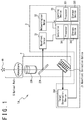
- Fig. 1 is a block circuit diagram that shows a configuration example of an optical compensation system 1A according to an embodiment.
- the optical compensation system 1A in Fig. 1 is provided with correction optics 2 and a control system 3.
- the optical compensation system 1A is configured to be able to observe light that reaches from a target 4A via the correction optics 2.
- the correction optics 2 is configured to perform optical correction under a control of the control system 3.
- the control system 3 is configured to control the correction optics 2.
- the correction optics 2 is provided with wavefront correction optics 21, ground optics 22A and a half mirror 23A.
- the wavefront correction optics 21 corrects the wavefront of the light that reaches from the target 4A under a control of the control system 3.
- the wavefront correction optics 21 is, for example, a deformable mirror.
- the ground optics 22A are, for example, optics such as a telescope arranged on the ground, and are configured to guide the light that reaches from the target 4A to the wavefront correction optics 21.
- the ground optics 22A are configured, for example, as a combination of various optical devices such as a lens or a mirror.
- the half mirror 23A is configured to guide a part of the light that reaches from the target 4A to the wavefront correction optics 21 and guide a rest thereof to the control system 3.
- the half mirror 23A is arranged in a path that the light that reaches from the target 4A to the target observation device 35A follows, and in particular, is arranged between the ground optics 22A and the wavefront correction optics 21.
- the half mirror 23A may be configured to be movable out of this path in a practical stage that will be described later.
- the control system 3 is provided with a wavefront sensor 31, a meteorological meter 32, a learning device 33, a controller 34 and a target observation device 35A.
- the wavefront sensor 31 is configured to receive the light that reaches from the target 4A via the half mirror 23A and measure wavefront disturbance of this light to generate wavefront information.
- the meteorological meter 32 is configured to observe weather to generate weather information.
- An Artificial Intelligence (AI) that outputs wavefront information based on weather information, is made to learn by the learning device 33.
- the controller 34 is configured to control the wavefront correction optics 21 based on all or a part of the wavefront information, the weather information and learning result information.
- the target observation device 35A is configured to receive the light that reaches from the target 4A, via the wavefront correction optics 21, and provide observation information obtained by observing the target 4A by use of this light to the controller 34.
- the learning device 33 is provided with a processor 331 and a storage device 332.
- the processor 331 executes a program stored in the storage device 332 to make the AI learn and stores information of the AI that has learned in the storage device 332.
- the storage device 332 stores the program that the processor 331 executes and the information of the AI that has learned.
- the storage device 332 may further store all or a part of the wavefront information, the weather information and the observation information.
- any sensor may be used, without limitation to the meteorological meter 32.
- the controller 34 is provided with a processor 341 and a storage device 342.
- the processor 341 executes a program stored in the storage device 342 to generate a control signal to control the wavefront correction optics 21.
- the storage device 342 stores the program to be executed by the processor 341 and various data to be used by the processor 341 to generate the control signal.
- the controller 34 includes a computer for example.
- each of the learning device 33 and the controller 34 is provided with an interface that is not illustrated and is connected via those interfaces.
- the learning device 33 and the controller 34 perform transmission and reception of various data via those interfaces.
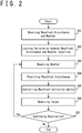
- Fig. 2 is a flowchart that shows a configuration example of processes included in the optical compensation method according to an embodiment. Operations of the optical compensation system 1A in Fig. 1 , that is, the optical compensation method, will be described with reference to Fig. 2 .
- the optical compensation method according to an embodiment is broadly divided into a storage stage, a learning stage and a practical stage.
- the flowchart in Fig. 2 includes seven steps in total, from a first step S01 to a seventh step S07. When the flowchart in Fig. 2 starts, the first step S01 is executed.
- the first step S01 is a storage stage to store a result of measurement and observation.
- the control system 3 observes wavefront disturbance and weather (conditions). More specifically, the wavefront sensor 31 of the control system 3 measures wavefront disturbance of the light that reaches from the target 4A to generate wavefront information.
- the meteorological meter 32 of the control system 3 observes weather to generate weather information.
- the wavefront information and the weather information that are generated are stored in the storage device 342 of the controller 34. It is preferable that the first step S01 is executed a plurality of times under various conditions so that the AI learns correlation between wavefront information and weather information in a higher accuracy in the following second step S02.
- the wavefront disturbance to be measured may be expressed, for example, as a group of a plurality of components that corresponds to coefficients of Zernike approximation polynomials, respectively.
- wavefront information to be generated may include a group of numerical values that correspond to coefficients of Zernike approximation polynomials, respectively.
- Weather to be observed includes, for example, all or a part of air temperature, humidity, wind speed, wind direction, atmospheric component such as aerosol, and the like.
- the weather information to be generated may include a group of numerical values that correspond to those weather observation results, respectively.
- wavefront information and weather information are stored in a database in association with observation condition information that indicates conditions in that measurement and observation have been performed to obtain such information.
- Observation conditions to be associated includes, for example, all or a part of latitude, longitude and altitude of the observation device, observation time, horizontal component and vertical component of observation direction, and the like. Associating and storing such information in a database is performed by the processor 341 of the controller 34 with reference to the storage device 342.
- Such information that is stored in a database is stored in the storage device 332 of the learning device 33.
- the second step S02 is executed after the first step S01.
- the second step S02 is the learning stage for the AI to learn correlation related to results of measurement and observation.
- the learning device 33 executes a program so that the AI learns correlations between wavefront disturbance and weather. More specifically, the processor 331 of the learning device 33 makes the AI learn correlation of wavefront disturbance and weather, and stores learning result information of the AI, that is obtained as a result, in the storage device 332. It should be noted that if various information obtained in the first step S01 is stored in the storage device 332, the learning device 33 can perform AI learning alone. In other words, by storing various information obtained in the first step S01 in the storage device 332, the second step S02 of the learning stage can be executed without using elements except the learning device 33 among elements included in the optical compensation system 1A.
- the third step S03 is executed after the second step S02.
- the third step S03 and later steps are a practical stage for correcting wavefront disturbance of light to observe the target 4A.
- the optical compensation system 1A in the practical stage may be configured as the example shown in Fig. 1 while elements that are not used in the practical stage may be omitted therefrom.
- Fig. 3 is a block circuit diagram that shows another configuration example of the optical compensation system 1A according to an embodiment. Compared with the optical compensation system 1A in Fig. 1 , the half mirror 23A, the wavefront sensor 31 and the learning device 33 are omitted from the optical compensation system 1A in Fig. 3 . In other words, the practical stage in the third step S03 and later steps can be executed without using the half mirror 23A, the wavefront sensor 31 and the learning device 33.
- the meteorological meter 32 observes weather. It is preferable that the observation of weather in the third step S03 is performed similarly to the case in the first step S01, as well. More specifically, it is preferable that the observation result, that is obtained by the weather observation of the meteorological meter 32, and the weather condition information, that indicates the condition in that this observation has been performed, are provided to the controller 34.
- the fourth step S04 is executed after the third step S03.
- the controller 34 predicts wavefront disturbance.
- the controller 34 executes the AI by use of the learning result information obtained in the step S02 and predicts a current wavefront disturbance without measuring, based on the observation result obtained in the third step S03.
- the controller 34 predicts the current wavefront disturbance based on the learning result information obtained in the second step S02 and the observation result obtained in the third step S03.
- the wavefront disturbance that is predicted will be referred to as wavefront disturbance prediction value.
- the learning result information obtained in the second step S02 is stored in the storage device 342 of the controller 34, at least before the fourth step S04 starts.
- the controller 34 may read out the learning result information by referring to the storage device 332 of the learning device 33.
- the fifth step S05 is executed after the fourth step S04.
- the controller 34 controls the wavefront correction optics 21. More specifically, the controller 34 controls the wavefront correction optics 21 so as to cancel the wavefront disturbance predicted in the fourth step S04. In other words, the controller 34 controls the wavefront correction optics 21 based on the wavefront disturbance prediction value. In further other words, the controller 34 controls the wavefront correction optics 21 based on the learning result obtained in the second step S02 and the observation result obtained in the third step S03. The controller 34 controls the wavefront correction optics 21 by generating a control signal to control the wavefront correction optics 21 and transmitting the control signal to the wavefront correction optics 21.
- the wavefront correction optics 21 corrects the wavefront of the light that reaches from the target 4A under control of the controller 34. If the wavefront correction optics 21 is a deformable mirror, the wavefront correction optics 21 performs a correction of the wavefront of the light so that the wavefront of the light after reflection approaches an ideal state, by deforming a mirror surface that reflects the light that reaches from the target 4A, under control of the controller 34. Wavefront of light being in an ideal state means that, for example, wavefront of light that reaches from a point on the target 4A is planar.
- the target observation device 35A observes the target 4A. More specifically, the target observation device 35A observes the target 4A by receiving the light, that reaches from the target 4A, and of which the wavefront is corrected by the wavefront correction optics 21. The target observation device 35A generates an image signal that indicates a result of the observation of the target 4A to transmit to the controller 34.
- the wavefront correction optics 21 may be controlled in accordance with changes in the weather. In this case, the third step S03 to the sixth step S06 that are included in the practical stage will be repeatedly executed. If the observation of the target 4A is not continued ("NO" in the seventh step S07), the flowchart in Fig. 2 ends when the sixth step S06 ends.
- the wavefront sensor 31 is used only in the first step S01 among the above-described steps. That is, the wavefront sensor 31 is not necessary in the following second step S02 and later steps and can be disconnected from the optical compensation system 1A.
- a wavefront sensor 31 that measures wavefront disturbance of light has a configuration in that a plurality of optical sensors is arranged in array and a scale thereof is relatively large. For this reason, it may be difficult to transport the wavefront sensor 31 to a site where the light wavefront is corrected.
- the wavefront sensor 31 being omittable from the optical compensation system 1A according to the present embodiment except in the first step S01 in storage stage means that a hardware of the optical compensation system 1A can be simplified in the learning stage and the practical stage.
- the controller 34 may select an arbitrary configuration, without limitation to an AI, as long as the wavefront disturbance can be calculated based on environmental information in the optical path 5 obtained by the meteorological meter 32 or the like.
- the wavefront sensor 31 can be omitted in the practical stage as described above, the wavefront sensor 31 can be used in the practical stage.
- the wavefront sensor 31 may perform operation of measuring wavefront in the third step S03 too, similarly to the case in the first step S01, in parallel with the operation of measuring weather by the meteorological meter 32.
- correction accuracy can be increased because convergence of wavefront correction can be speeded up by combining learning result.
- Fig. 4 is a block circuit diagram that shows a configuration example of an optical compensation system 1B according to an embodiment.
- the optical compensation system 1B in Fig. 4 has following differences compared to the optical compensation system 1A in Fig. 1 .
- the optical compensation system 1A in Fig. 1 observes light that reaches from the target 4A
- the optical compensation system 1B in Fig. 4 generates transmitted light 61, that is laser light, to irradiate the target 4B therewith.
- the optical compensation system 1B in Fig. 4 is further provided with, in addition to the elements of the optical compensation system 1A in Fig. 1 , a laser light source 6 that generates laser light.
- the optical compensation system 1B in Fig. 4 is provided with irradiation optics 22B instead of the ground optics 22A in the optical compensation system 1A in Fig. 1 .
- the optical compensation system 1A in Fig. 1 corrects the wavefront of the light that reaches from the target 4A
- the optical compensation system 1B in Fig. 4 corrects wavefront of the transmitted light 61 that is laser light irradiated to the target 4B.
- the optical compensation system 1B in Fig. 4 corrects the wavefront of the transmitted light 61 so that the wavefront of the laser light approaches an ideal state when the transmitted light 61 propagates the atmosphere in the optical path 5 and reaches the target 4B.
- This correction has characteristics opposite to the case of the optical compensation system 1A in Fig.1 in a meaning of being performed based on a state of the atmosphere in the optical path 5.
- the wavefront sensor 31 of the optical compensation system 1A in Fig. 1 observes the light that reaches from the target 4A via the atmosphere in the optical path 5 and the ground optics 22A, and via a reflection by the half mirror 23A.
- the optical compensation system 1B in Fig. 4 measures wavefront disturbance of reflected light 62 that is the transmitted light 61 generated by the laser light source 6, reaches the target 4B via the wavefront correction optics 21, a separation device 23B, the irradiation optics 22B and the atmosphere in the optical path 5, is reflected by a surface of the target 4B, further travels via the atmosphere in the optical path 5 and the irradiation optics 22B to be partially reflected by the separation device 23B.
- the separation device 23B that is arranged instead of the half mirror 23A is configured to guide only the reflected light 62 to the wavefront sensor 31 and so that the transmitted light 61 is not incident on the wavefront sensor 31.
- the optical compensation system 1B in Fig. 4 is provided with the target observation device 35B instead of the target observation device 35A of the optical compensation system 1A in Fig. 1 .
- the target observation device 35A of the optical compensation system 1A in Fig. 1 observes the light that reaches from the target 4A via the atmosphere in the optical path 5, the ground optics 22A, the half mirror 23A and the wavefront correction optics 21.
- the 4 may observe the reflected light 62 that is the transmitted light 61 generated by the laser light source 6, reaches the target 4B via the wavefront correction optics 21, the separation device 23B, the irradiation optics 22B and the atmosphere in the optical path 5 and reflected on the surface of the target 4B.
- optical compensation system 1B in Fig. 4 is similar to the optical compensation system 1A in Fig. 1 , further detailed explanation is omitted.
- Fig. 5 is a flowchart that indicates a configuration example of processes included in an optical compensation method according to an embodiment.
- the flowchart in Fig. 5 includes a total of eight steps from the first step S11 to the eighth step S18.
- the first step S11 to the fifth step S15 are executed in this order.
- the contents of the first step S11 to the fifth step S15 are same as the contents of the first step S01 to the fifth step S05 in Fig. 2 , respectively, further detailed explanation is omitted.
- the sixth step S16 is executed after the firth step S15.
- the optical compensation system 1B irradiates light to the target 4B. More specifically, at first, the laser light source 6 generates the transmitted light 61 that is laser light. Next, the wavefront correction optics 21 corrects the wavefront of the transmitted light 61. Next, the separation device 23B transmits the transmitted light 61 and the irradiation optics 22B irradiates the target 4B with the transmitted light 61.
- the wavefront of the transmitted light 61 is corrected so that the wavefront of the transmitted light 61 approaches an ideal state when the transmitted light 61 reaches the target 4B after propagating in the atmosphere in the optical path 5.
- the wavefront of the transmitted light 61 is not necessarily in an ideal state or close to an ideal state immediately after being corrected by the wavefront correction optics 21.
- the seventh step S17 is executed after the sixth step S16.
- the target observation device 35B observes the target 4B. More specifically, the target observation device 35B optically observes the surface of the target 4B, especially a part thereof that is irradiated with the transmitted light 61. The target observation device 35B generates an image signal that indicates a result of the observation of the target 4B and transmits the image signal to the controller 34.
- the eighth step S18 is executed after the seventh step S07.
- the target observation device 35B observes the target 4B, generates a signal that indicates a result of the observation and transmits the signal to the controller 34.
- the determination whether to continue irradiating the target 4B with light may be performed by a user or performed by the controller 34, based on the result of the observation by the target observation device 35B. It should be noted that the controller 34 may determine whether an influence, that the target 4B has received by irradiation of the transmitted light 61 that is laser light, has reached a desired threshold value, based on a received signal.
- a physical quantity specified by the desired threshold value may be brightness, temperature, an amount of disappearance or the like and are not limited by those examples.
- the determination whether to continue irradiating the target 4B with light may be performed by a user or performed by the controller 34, based on the determination whether the influence the target 4B has received has reached a desired threshold value.
- the controller 34 may perform a feedback control of the wavefront correction optics 21 based on a result of observation of the target 4B by the target observation device 35B. In addition, by repeatedly executing the practical stage, the controller 34 can control the wavefront correction optics 21 based on changes of the weather.
- wavefront correction can be performed by the optical compensation system 1B and the optical compensation method, even in a laser light transmission that transfers light energy for example.
- the wavefront sensor 31 can be omitted at the practical stage, in the present embodiment too.
- a separation device 23B that separates the transmitted light 61 and the reflected light 62 needs to be provided to the correction optics 2.
- Fig. 6 is a block circuit diagram that shows another configuration example of the optical compensation system according to an embodiment. Compared to the optical compensation system 1B in Fig. 4 , the separation device 23B, the wavefront sensor 31 and the learning device 33 are omitted in the optical compensation system 1B in Fig. 6 .
Landscapes
- Physics & Mathematics (AREA)
- General Physics & Mathematics (AREA)
- Optics & Photonics (AREA)
- Engineering & Computer Science (AREA)
- Computer Networks & Wireless Communication (AREA)
- Electromagnetism (AREA)
- Radar, Positioning & Navigation (AREA)
- Remote Sensing (AREA)
- Astronomy & Astrophysics (AREA)
- Telescopes (AREA)
- Mechanical Light Control Or Optical Switches (AREA)
Abstract
Description
- The present invention relates to an optical compensation system and an optical compensation method.
- When light propagates in an atmosphere, a wavefront of the light is disturbed by influences of atmospheric fluctuation or the like. For example, in a technical field of astronomical observation and the like, an original resolution of a telescope may not be exhibited and images taken through the telescope may be blurred.
- In order to resolve such problems, a technique called optical compensation is developed. As an example, a technique of compensating a wavefront of light by measuring a disturbance of the wavefront of the light propagated through an atmosphere and controlling a deformable mirror based on a result of the measuring.
- In relation with the above, patent literature 1 (Japanese Patent Publication No.
2011-185567 - The high-power laser irradiation apparatus of the patent literature 1 (Japanese Patent Publication No.
2011-185567 - [Patent Literature 1] Japanese Patent Publication No.
2011-185567 - In view of the above situation, a system or a method of optical compensation of performing optical compensation based on environmental information will be provided. Other problem to be solved and novel features will become apparent from disclosures of the present description and attached drawings.
- According to an embodiment, an optical compensation system is provided with wavefront correction optics, a sensor and a controller. The wavefront correction optics corrects a wavefront of light that passes through a given optical path. The sensor obtains environmental information in the optical path. The controller calculates, based on the environmental information, a predicted wavefront disturbance of the light that has passed through the optical path and controls the wavefront correction optics so as to cancel the predicted wavefront disturbance.
- According to an embodiment, an optical compensation method includes obtaining environmental information in a given optical path and controlling wavefront correction optics based on the environmental information. The controlling includes calculating a predicted wavefront disturbance based on weather conditions and correlation information and generating a control signal so as to cancel the predicted wavefront disturbance.
- According to the above-described embodiment, optical compensation can be predictively performed based on environmental information.
-
- [
Fig. 1] Fig. 1 is a block circuit diagram that shows a configuration example of an optical compensation system according to an embodiment. - [
Fig. 2] Fig. 2 is a flowchart that shows a configuration example of processes included in an optical compensation method according to an embodiment. - [
Fig. 3] Fig. 3 is a block circuit diagram that shows another configuration example of the optical compensation system according to an embodiment. - [
Fig. 4] Fig. 4 is a block circuit diagram that shows a configuration example of an optical compensation system according to an embodiment. - [
Fig. 5] Fig. 5 is a flowchart that shows a configuration example of processes included in an optical compensation method according to an embodiment. - [
Fig. 6] Fig. 6 is a block circuit diagram that shows another configuration example of the optical compensation system according to an embodiment. - Embodiments of an optical compensation system and an optical compensation method according to the present invention will be explained in the following, with reference to attached drawings.
-
Fig. 1 is a block circuit diagram that shows a configuration example of anoptical compensation system 1A according to an embodiment. Theoptical compensation system 1A inFig. 1 is provided withcorrection optics 2 and acontrol system 3. - Herein, the
optical compensation system 1A is configured to be able to observe light that reaches from atarget 4A via thecorrection optics 2. Thecorrection optics 2 is configured to perform optical correction under a control of thecontrol system 3. Thecontrol system 3 is configured to control thecorrection optics 2. - The
correction optics 2 is provided withwavefront correction optics 21,ground optics 22A and ahalf mirror 23A. Herein, the wavefront correction optics 21 corrects the wavefront of the light that reaches from thetarget 4A under a control of thecontrol system 3. Thewavefront correction optics 21 is, for example, a deformable mirror. Theground optics 22A are, for example, optics such as a telescope arranged on the ground, and are configured to guide the light that reaches from thetarget 4A to thewavefront correction optics 21. Theground optics 22A are configured, for example, as a combination of various optical devices such as a lens or a mirror. Thehalf mirror 23A is configured to guide a part of the light that reaches from thetarget 4A to thewavefront correction optics 21 and guide a rest thereof to thecontrol system 3. In the present embodiment, thehalf mirror 23A is arranged in a path that the light that reaches from thetarget 4A to thetarget observation device 35A follows, and in particular, is arranged between theground optics 22A and thewavefront correction optics 21. In the present embodiment, thehalf mirror 23A may be configured to be movable out of this path in a practical stage that will be described later. - The
control system 3 is provided with awavefront sensor 31, ameteorological meter 32, alearning device 33, acontroller 34 and atarget observation device 35A. Thewavefront sensor 31 is configured to receive the light that reaches from thetarget 4A via thehalf mirror 23A and measure wavefront disturbance of this light to generate wavefront information. Themeteorological meter 32 is configured to observe weather to generate weather information. An Artificial Intelligence (AI), that outputs wavefront information based on weather information, is made to learn by thelearning device 33. Thecontroller 34 is configured to control thewavefront correction optics 21 based on all or a part of the wavefront information, the weather information and learning result information. Thetarget observation device 35A is configured to receive the light that reaches from thetarget 4A, via thewavefront correction optics 21, and provide observation information obtained by observing thetarget 4A by use of this light to thecontroller 34. - The
learning device 33 is provided with aprocessor 331 and astorage device 332. Theprocessor 331 executes a program stored in thestorage device 332 to make the AI learn and stores information of the AI that has learned in thestorage device 332. Thestorage device 332 stores the program that theprocessor 331 executes and the information of the AI that has learned. Thestorage device 332 may further store all or a part of the wavefront information, the weather information and the observation information. In addition, if a state of the atmosphere in theoptical path 5, or an environment of theoptical path 5 in other words, can be measured, any sensor may be used, without limitation to themeteorological meter 32. - The
controller 34 is provided with aprocessor 341 and astorage device 342. Theprocessor 341 executes a program stored in thestorage device 342 to generate a control signal to control thewavefront correction optics 21. Thestorage device 342 stores the program to be executed by theprocessor 341 and various data to be used by theprocessor 341 to generate the control signal. Thecontroller 34 includes a computer for example. - In an embodiment, each of the
learning device 33 and thecontroller 34 is provided with an interface that is not illustrated and is connected via those interfaces. Thelearning device 33 and thecontroller 34 perform transmission and reception of various data via those interfaces. -
Fig. 2 is a flowchart that shows a configuration example of processes included in the optical compensation method according to an embodiment. Operations of theoptical compensation system 1A inFig. 1 , that is, the optical compensation method, will be described with reference toFig. 2 . - The optical compensation method according to an embodiment is broadly divided into a storage stage, a learning stage and a practical stage. In addition, the flowchart in
Fig. 2 includes seven steps in total, from a first step S01 to a seventh step S07. When the flowchart inFig. 2 starts, the first step S01 is executed. - The first step S01 is a storage stage to store a result of measurement and observation. In the first step S01, the
control system 3 observes wavefront disturbance and weather (conditions). More specifically, thewavefront sensor 31 of thecontrol system 3 measures wavefront disturbance of the light that reaches from thetarget 4A to generate wavefront information. In addition, themeteorological meter 32 of thecontrol system 3 observes weather to generate weather information. The wavefront information and the weather information that are generated are stored in thestorage device 342 of thecontroller 34. It is preferable that the first step S01 is executed a plurality of times under various conditions so that the AI learns correlation between wavefront information and weather information in a higher accuracy in the following second step S02. - The wavefront disturbance to be measured may be expressed, for example, as a group of a plurality of components that corresponds to coefficients of Zernike approximation polynomials, respectively. In other words, wavefront information to be generated may include a group of numerical values that correspond to coefficients of Zernike approximation polynomials, respectively.
- Weather to be observed includes, for example, all or a part of air temperature, humidity, wind speed, wind direction, atmospheric component such as aerosol, and the like. In other words, the weather information to be generated may include a group of numerical values that correspond to those weather observation results, respectively.
- It is preferable that wavefront information and weather information are stored in a database in association with observation condition information that indicates conditions in that measurement and observation have been performed to obtain such information. Observation conditions to be associated includes, for example, all or a part of latitude, longitude and altitude of the observation device, observation time, horizontal component and vertical component of observation direction, and the like. Associating and storing such information in a database is performed by the
processor 341 of thecontroller 34 with reference to thestorage device 342. - Such information that is stored in a database is stored in the
storage device 332 of thelearning device 33. The second step S02 is executed after the first step S01. - The second step S02 is the learning stage for the AI to learn correlation related to results of measurement and observation. In the second step S02, the
learning device 33 executes a program so that the AI learns correlations between wavefront disturbance and weather. More specifically, theprocessor 331 of thelearning device 33 makes the AI learn correlation of wavefront disturbance and weather, and stores learning result information of the AI, that is obtained as a result, in thestorage device 332. It should be noted that if various information obtained in the first step S01 is stored in thestorage device 332, thelearning device 33 can perform AI learning alone. In other words, by storing various information obtained in the first step S01 in thestorage device 332, the second step S02 of the learning stage can be executed without using elements except thelearning device 33 among elements included in theoptical compensation system 1A. The third step S03 is executed after the second step S02. - The third step S03 and later steps are a practical stage for correcting wavefront disturbance of light to observe the
target 4A. Theoptical compensation system 1A in the practical stage may be configured as the example shown inFig. 1 while elements that are not used in the practical stage may be omitted therefrom.Fig. 3 is a block circuit diagram that shows another configuration example of theoptical compensation system 1A according to an embodiment. Compared with theoptical compensation system 1A inFig. 1 , thehalf mirror 23A, thewavefront sensor 31 and thelearning device 33 are omitted from theoptical compensation system 1A inFig. 3 . In other words, the practical stage in the third step S03 and later steps can be executed without using thehalf mirror 23A, thewavefront sensor 31 and thelearning device 33. - In the third step S03, the
meteorological meter 32 observes weather. It is preferable that the observation of weather in the third step S03 is performed similarly to the case in the first step S01, as well. More specifically, it is preferable that the observation result, that is obtained by the weather observation of themeteorological meter 32, and the weather condition information, that indicates the condition in that this observation has been performed, are provided to thecontroller 34. The fourth step S04 is executed after the third step S03. - In the fourth step S04, the
controller 34 predicts wavefront disturbance. Thecontroller 34 executes the AI by use of the learning result information obtained in the step S02 and predicts a current wavefront disturbance without measuring, based on the observation result obtained in the third step S03. In other words, thecontroller 34 predicts the current wavefront disturbance based on the learning result information obtained in the second step S02 and the observation result obtained in the third step S03. In the following, the wavefront disturbance that is predicted will be referred to as wavefront disturbance prediction value. - If the
learning device 33 and thecontroller 34 are not connected at the fourth step S04, the learning result information obtained in the second step S02 is stored in thestorage device 342 of thecontroller 34, at least before the fourth step S04 starts. In an opposite case, if thelearning device 33 and thecontroller 34 are connected at the fourth step S04, thecontroller 34 may read out the learning result information by referring to thestorage device 332 of thelearning device 33. The fifth step S05 is executed after the fourth step S04. - In the step S05, the
controller 34 controls thewavefront correction optics 21. More specifically, thecontroller 34 controls thewavefront correction optics 21 so as to cancel the wavefront disturbance predicted in the fourth step S04. In other words, thecontroller 34 controls thewavefront correction optics 21 based on the wavefront disturbance prediction value. In further other words, thecontroller 34 controls thewavefront correction optics 21 based on the learning result obtained in the second step S02 and the observation result obtained in the third step S03. Thecontroller 34 controls thewavefront correction optics 21 by generating a control signal to control thewavefront correction optics 21 and transmitting the control signal to thewavefront correction optics 21. - The
wavefront correction optics 21 corrects the wavefront of the light that reaches from thetarget 4A under control of thecontroller 34. If thewavefront correction optics 21 is a deformable mirror, thewavefront correction optics 21 performs a correction of the wavefront of the light so that the wavefront of the light after reflection approaches an ideal state, by deforming a mirror surface that reflects the light that reaches from thetarget 4A, under control of thecontroller 34. Wavefront of light being in an ideal state means that, for example, wavefront of light that reaches from a point on thetarget 4A is planar. - In the sixth step S06, the
target observation device 35A observes thetarget 4A. More specifically, thetarget observation device 35A observes thetarget 4A by receiving the light, that reaches from thetarget 4A, and of which the wavefront is corrected by thewavefront correction optics 21. Thetarget observation device 35A generates an image signal that indicates a result of the observation of thetarget 4A to transmit to thecontroller 34. - If the observation of the
target 4A is continuously performed after the sixth step S06 is ended ("YES" in the seventh step S07), thewavefront correction optics 21 may be controlled in accordance with changes in the weather. In this case, the third step S03 to the sixth step S06 that are included in the practical stage will be repeatedly executed. If the observation of thetarget 4A is not continued ("NO" in the seventh step S07), the flowchart inFig. 2 ends when the sixth step S06 ends. - It is to be noted that in the present embodiment the
wavefront sensor 31 is used only in the first step S01 among the above-described steps. That is, thewavefront sensor 31 is not necessary in the following second step S02 and later steps and can be disconnected from theoptical compensation system 1A. Generally, awavefront sensor 31 that measures wavefront disturbance of light has a configuration in that a plurality of optical sensors is arranged in array and a scale thereof is relatively large. For this reason, it may be difficult to transport thewavefront sensor 31 to a site where the light wavefront is corrected. From this point of view, thewavefront sensor 31 being omittable from theoptical compensation system 1A according to the present embodiment except in the first step S01 in storage stage means that a hardware of theoptical compensation system 1A can be simplified in the learning stage and the practical stage. For this reason, thecontroller 34 may select an arbitrary configuration, without limitation to an AI, as long as the wavefront disturbance can be calculated based on environmental information in theoptical path 5 obtained by themeteorological meter 32 or the like. - In addition, from another point of view, due to a principle with that the
wavefront sensor 31 measures wavefront disturbance of light, accuracy and speed thereof are in a trade-off relationship. In other words, measurement speed decrease when increasing measurement accuracy, and in opposite, the measurement accuracy decreases when increasing measurement speed. In the practical stage of the present embodiment, as no real time measurement of wavefront disturbance by use ofwavefront sensor 31 is performed, accuracy and speed of wavefront compensation are compatible. - It should be noted that, although the
wavefront sensor 31 can be omitted in the practical stage as described above, thewavefront sensor 31 can be used in the practical stage. In this case, thewavefront sensor 31 may perform operation of measuring wavefront in the third step S03 too, similarly to the case in the first step S01, in parallel with the operation of measuring weather by themeteorological meter 32. When using thewavefront sensor 31 in the practical stage, correction accuracy can be increased because convergence of wavefront correction can be speeded up by combining learning result. -
Fig. 4 is a block circuit diagram that shows a configuration example of anoptical compensation system 1B according to an embodiment. Theoptical compensation system 1B inFig. 4 has following differences compared to theoptical compensation system 1A inFig. 1 . - As a first difference, while the
optical compensation system 1A inFig. 1 observes light that reaches from thetarget 4A, theoptical compensation system 1B inFig. 4 generates transmitted light 61, that is laser light, to irradiate thetarget 4B therewith. For this reason, theoptical compensation system 1B inFig. 4 is further provided with, in addition to the elements of theoptical compensation system 1A inFig. 1 , alaser light source 6 that generates laser light. In addition, theoptical compensation system 1B inFig. 4 is provided withirradiation optics 22B instead of theground optics 22A in theoptical compensation system 1A inFig. 1 . - As a second difference, while the
optical compensation system 1A inFig. 1 corrects the wavefront of the light that reaches from thetarget 4A, theoptical compensation system 1B inFig. 4 corrects wavefront of the transmitted light 61 that is laser light irradiated to thetarget 4B. Herein, theoptical compensation system 1B inFig. 4 corrects the wavefront of the transmitted light 61 so that the wavefront of the laser light approaches an ideal state when the transmittedlight 61 propagates the atmosphere in theoptical path 5 and reaches thetarget 4B. This correction has characteristics opposite to the case of theoptical compensation system 1A inFig.1 in a meaning of being performed based on a state of the atmosphere in theoptical path 5. - As a third difference, the
wavefront sensor 31 of theoptical compensation system 1A inFig. 1 observes the light that reaches from thetarget 4A via the atmosphere in theoptical path 5 and theground optics 22A, and via a reflection by thehalf mirror 23A. On the other hand, theoptical compensation system 1B inFig. 4 measures wavefront disturbance of reflected light 62 that is the transmitted light 61 generated by thelaser light source 6, reaches thetarget 4B via thewavefront correction optics 21, aseparation device 23B, theirradiation optics 22B and the atmosphere in theoptical path 5, is reflected by a surface of thetarget 4B, further travels via the atmosphere in theoptical path 5 and theirradiation optics 22B to be partially reflected by theseparation device 23B. Herein, theseparation device 23B that is arranged instead of thehalf mirror 23A is configured to guide only the reflected light 62 to thewavefront sensor 31 and so that the transmittedlight 61 is not incident on thewavefront sensor 31. - As the fourth difference, the
optical compensation system 1B inFig. 4 is provided with thetarget observation device 35B instead of thetarget observation device 35A of theoptical compensation system 1A inFig. 1 . Herein, thetarget observation device 35A of theoptical compensation system 1A inFig. 1 observes the light that reaches from thetarget 4A via the atmosphere in theoptical path 5, theground optics 22A, thehalf mirror 23A and thewavefront correction optics 21. On the other hand, theoptical compensation system 1B inFig. 4 may observe the reflected light 62 that is the transmitted light 61 generated by thelaser light source 6, reaches thetarget 4B via thewavefront correction optics 21, theseparation device 23B, theirradiation optics 22B and the atmosphere in theoptical path 5 and reflected on the surface of thetarget 4B. - As other configuration of the
optical compensation system 1B inFig. 4 is similar to theoptical compensation system 1A inFig. 1 , further detailed explanation is omitted. -
Fig. 5 is a flowchart that indicates a configuration example of processes included in an optical compensation method according to an embodiment. The flowchart inFig. 5 includes a total of eight steps from the first step S11 to the eighth step S18. When the flowchart inFig. 5 starts, the first step S11 to the fifth step S15 are executed in this order. Herein, as the contents of the first step S11 to the fifth step S15 are same as the contents of the first step S01 to the fifth step S05 inFig. 2 , respectively, further detailed explanation is omitted. The sixth step S16 is executed after the firth step S15. - In the sixth step S16, the
optical compensation system 1B irradiates light to thetarget 4B. More specifically, at first, thelaser light source 6 generates the transmitted light 61 that is laser light. Next, thewavefront correction optics 21 corrects the wavefront of the transmittedlight 61. Next, theseparation device 23B transmits the transmittedlight 61 and theirradiation optics 22B irradiates thetarget 4B with the transmittedlight 61. - In the sixth step S16, as described above, the wavefront of the transmitted
light 61 is corrected so that the wavefront of the transmitted light 61 approaches an ideal state when the transmittedlight 61 reaches thetarget 4B after propagating in the atmosphere in theoptical path 5. In other words, the wavefront of the transmittedlight 61 is not necessarily in an ideal state or close to an ideal state immediately after being corrected by thewavefront correction optics 21. The seventh step S17 is executed after the sixth step S16. - In the seventh step S17, the
target observation device 35B observes thetarget 4B. More specifically, thetarget observation device 35B optically observes the surface of thetarget 4B, especially a part thereof that is irradiated with the transmittedlight 61. Thetarget observation device 35B generates an image signal that indicates a result of the observation of thetarget 4B and transmits the image signal to thecontroller 34. The eighth step S18 is executed after the seventh step S07. - In the eighth step S18, it is determined whether to continue irradiating the
target 4B with light. More specifically, thetarget observation device 35B observes thetarget 4B, generates a signal that indicates a result of the observation and transmits the signal to thecontroller 34. The determination whether to continue irradiating thetarget 4B with light may be performed by a user or performed by thecontroller 34, based on the result of the observation by thetarget observation device 35B. It should be noted that thecontroller 34 may determine whether an influence, that thetarget 4B has received by irradiation of the transmitted light 61 that is laser light, has reached a desired threshold value, based on a received signal. Herein, a physical quantity specified by the desired threshold value may be brightness, temperature, an amount of disappearance or the like and are not limited by those examples. The determination whether to continue irradiating thetarget 4B with light may be performed by a user or performed by thecontroller 34, based on the determination whether the influence thetarget 4B has received has reached a desired threshold value. - If a result of the determination is "YES", that is, if it is determined to continue irradiating the
target 4B with light, the third step S13 to the eighth step S18 that are included in the practical stage will be executed again after the eighth step S18. At that time, thecontroller 34 may perform a feedback control of thewavefront correction optics 21 based on a result of observation of thetarget 4B by thetarget observation device 35B. In addition, by repeatedly executing the practical stage, thecontroller 34 can control thewavefront correction optics 21 based on changes of the weather. - If a result of the determination is "NO", that is, if it is determined not to continue irradiating the
target 4B with light, the flowchart inFig. 5 ends when the eighth step S18 ends. - As described above, according to the present embodiment, wavefront correction can be performed by the
optical compensation system 1B and the optical compensation method, even in a laser light transmission that transfers light energy for example. In addition, similarly to the case of the embodiment shown inFigs. 1 to 3 , thewavefront sensor 31 can be omitted at the practical stage, in the present embodiment too. When trying to correct wavefront by a real time measurement of the wavefront disturbance by use of thewavefront sensor 31, as an area to observe atmospheric fluctuation matches theoptical path 5 where the laser light passes through, aseparation device 23B that separates the transmittedlight 61 and the reflected light 62 needs to be provided to thecorrection optics 2. From this point of view, in the present embodiment in that thewavefront sensor 31 can be omitted in the practical stage, the hardware configuration can be significantly simplified compared to related technologies.Fig. 6 is a block circuit diagram that shows another configuration example of the optical compensation system according to an embodiment. Compared to theoptical compensation system 1B inFig. 4 , theseparation device 23B, thewavefront sensor 31 and thelearning device 33 are omitted in theoptical compensation system 1B inFig. 6 . - Although the invention made by the inventor has been described above in detail based on embodiments, it is needless to say that the present invention is not limited to the above-described embodiments and various modifications can be made without departing from the gist thereof. In addition, each of features described in the above embodiments can be freely combined within a technically consistent range.
- The present application claims priority based on the Japanese Patent Application No.
2018-212665 filed on November 13, 2018
Claims (10)
- An optical compensation system comprising:wavefront correction optics configured to correct a wavefront of light that passes through a given optical path;a sensor configured to obtain environmental information in the optical path; anda controller configured to calculate, based on the environmental information, a predicted wavefront disturbance of the light that has passed through the optical path and control the wavefront correction optics so as to cancel the predicted wavefront disturbance.
- The optical compensation system according to claim 1,
wherein the controller is further configured to control the wavefront correction optics based on a fluctuation of the obtained environmental information. - The optical compensation system according to claim 1 or 2,
wherein the sensor includes a meteorological meter configured to observe weather. - The optical compensation system according to any one of claims 1 to 3, further comprising:ground optics arranged so that the light that has passed through the optical path further passes therethrough; anda target observation device configured to observe the light that reaches from an external target via the ground optics and the wavefront correction optics.
- The optical compensation system according to any one of claims 1 to 3, further comprising:a light source configured to generate the light; andirradiation optics arranged in the optical path and configured to irradiate an external target with the light that travels to the optical path via the wavefront correction optics.
- The optical compensation system according to claim 5, further comprising:a target observation device configured to observe the target,wherein the controller is further configured to perform a feedback control of the wavefront correction optics further based on a fluctuation of a result of an observation by the target observation device.
- The optical compensation system according to any one of claims 1 to 6, further comprising:
a wavefront sensor configured to measure the wavefront disturbance. - The optical compensation system according to any one of claims 1 to 7,
wherein the controller is further configured to execute an Artificial Intelligence (AI), that is configured to receive an input of the environmental information and outputs the predicted wavefront disturbance of the light that has passed through the optical path, to calculate the predicted wavefront disturbance. - The optical compensation system according to claim 8, further comprising:
a learning device configured to make the AI learn. - An optical compensation method including:obtaining, by a sensor, environmental information in a given optical path;calculating, by a controller, a predicted wavefront disturbance of light that has passed through the optical path, based on the environmental information; andcontrolling, by the controller, wavefront correction optics so as to cancel the predicted wavefront disturbance.
Applications Claiming Priority (2)
| Application Number | Priority Date | Filing Date | Title |
|---|---|---|---|
| JP2018212665 | 2018-11-13 | ||
| PCT/JP2019/031028 WO2020100360A1 (en) | 2018-11-13 | 2019-08-07 | Corrective optical system and optical correction method |
Publications (2)
| Publication Number | Publication Date |
|---|---|
| EP3825753A1 true EP3825753A1 (en) | 2021-05-26 |
| EP3825753A4 EP3825753A4 (en) | 2021-10-06 |
Family
ID=70731091
Family Applications (1)
| Application Number | Title | Priority Date | Filing Date |
|---|---|---|---|
| EP19884564.6A Pending EP3825753A4 (en) | 2018-11-13 | 2019-08-07 | OPTICAL CORRECTION SYSTEM AND OPTICAL CORRECTION METHOD |
Country Status (4)
| Country | Link |
|---|---|
| US (1) | US11977219B2 (en) |
| EP (1) | EP3825753A4 (en) |
| JP (1) | JP7208598B2 (en) |
| WO (1) | WO2020100360A1 (en) |
Families Citing this family (3)
| Publication number | Priority date | Publication date | Assignee | Title |
|---|---|---|---|---|
| US12206450B2 (en) * | 2020-06-23 | 2025-01-21 | Nippon Telegraph And Telephone Corporation | Phase difference distribution estimation method and phase difference distribution estimation apparatus |
| CN115291632A (en) * | 2022-06-21 | 2022-11-04 | 火星营地(北京)教育科技有限公司 | Laser-based celestial body position guiding method, device and medium |
| WO2025104888A1 (en) * | 2023-11-16 | 2025-05-22 | 日本電信電話株式会社 | Control device, light-receiving device, learning device, control method, and program |
Family Cites Families (8)
| Publication number | Priority date | Publication date | Assignee | Title |
|---|---|---|---|---|
| JPH1048337A (en) * | 1996-08-07 | 1998-02-20 | Hitachi Ltd | Laser ranging device and laser ranging method |
| JP2003075762A (en) * | 2001-08-31 | 2003-03-12 | Fuji Photo Film Co Ltd | Light beam scanning method and device |
| US7146060B2 (en) * | 2002-12-27 | 2006-12-05 | Cicchiello James M | Real-time correction of phase distortion |
| JP2011185567A (en) * | 2010-03-10 | 2011-09-22 | Mitsubishi Electric Corp | High output laser irradiation device |
| US8362410B2 (en) | 2010-07-26 | 2013-01-29 | Raytheon Company | Source-independent beam director and control system for a high-energy electromagnetic radiation source |
| US9664781B2 (en) * | 2013-03-14 | 2017-05-30 | The United States Of America, As Represented By The Secretary Of The Navy | Time-gated image reconstruction using phase conjugation |
| JPWO2016047100A1 (en) * | 2014-09-25 | 2017-07-06 | 日本電気株式会社 | Spatial optical receiver, spatial optical communication system, and spatial optical communication method |
| EP3370486A1 (en) * | 2017-03-02 | 2018-09-05 | ASML Netherlands B.V. | Radiation source |
-
2019
- 2019-08-07 EP EP19884564.6A patent/EP3825753A4/en active Pending
- 2019-08-07 JP JP2020556603A patent/JP7208598B2/en active Active
- 2019-08-07 US US17/269,727 patent/US11977219B2/en active Active
- 2019-08-07 WO PCT/JP2019/031028 patent/WO2020100360A1/en not_active Ceased
Also Published As
| Publication number | Publication date |
|---|---|
| US20210318534A1 (en) | 2021-10-14 |
| JPWO2020100360A1 (en) | 2021-09-24 |
| JP7208598B2 (en) | 2023-01-19 |
| EP3825753A4 (en) | 2021-10-06 |
| US11977219B2 (en) | 2024-05-07 |
| WO2020100360A1 (en) | 2020-05-22 |
Similar Documents
| Publication | Publication Date | Title |
|---|---|---|
| US11977219B2 (en) | Optical compensation system and optical compensation method | |
| US8907260B2 (en) | Extended source wavefront sensor through optical correlation with a change in centroid position of light corresponding to a magnitude of tip/tilt aberration of optical jitter | |
| US20190064332A1 (en) | Photonics integrated phase measurement | |
| EP3465272A1 (en) | High-performance beam director for high-power laser systems or other systems | |
| JP6278848B2 (en) | Shape estimation apparatus, endoscope system including the same, and program for shape estimation | |
| US20220018718A1 (en) | Wavefront curvature sensor involving temporal sampling of the image intensity distribution | |
| US11271645B2 (en) | Beam divergence adjustment of a communication beam based on state disturbance estimations | |
| US11342989B2 (en) | Method for measuring transmission loss of optical fiber and OTDR measurement device | |
| US12379187B2 (en) | Laser irradiation apparatus and laser irradiation method | |
| CN111722205A (en) | Calibration method, system, device, equipment and storage medium for laser ranging | |
| US11764877B2 (en) | Optic signal receiver, optic communication system and optic communication method | |
| DK1883786T3 (en) | Amplification correction for semi-active laser searchers based on onboard light source | |
| WO2021071556A1 (en) | System and method for predictive compensation of uplink laser beam atmospheric jitter for high energy laser weapon systems | |
| KR102833311B1 (en) | Thermal image camera | |
| EP3182082A1 (en) | Gain normalization | |
| CN112432768B (en) | Hyperspectral image-based optical multi-aperture imaging system translation error measurement method | |
| RU2242019C2 (en) | Method for determination of co-ordinates of distant object on terrain and device for its realization | |
| CA3012551A1 (en) | Method for calibrating an active sensor system | |
| KR20240051727A (en) | Fusion tracking device and method for cameras with difference field-of-views mounted on a gimbal | |
| US8416404B2 (en) | Method and system for measurement and correction of thermally induced changes of boresight, effective focal length, and focus | |
| EP2630532B1 (en) | Apparatus, method and computer program for giving an indication of a detected context | |
| US20240036180A1 (en) | Long distance lidar test system | |
| O'Toole et al. | Fiber bundle-based beam tracking demonstrated across 30 km terrestrial FSO communications link | |
| US20230135206A1 (en) | Determining attenuation rate using imagery | |
| JPH11160419A (en) | Laser radar alignment adjustment device |
Legal Events
| Date | Code | Title | Description |
|---|---|---|---|
| STAA | Information on the status of an ep patent application or granted ep patent |
Free format text: STATUS: THE INTERNATIONAL PUBLICATION HAS BEEN MADE |
|
| PUAI | Public reference made under article 153(3) epc to a published international application that has entered the european phase |
Free format text: ORIGINAL CODE: 0009012 |
|
| STAA | Information on the status of an ep patent application or granted ep patent |
Free format text: STATUS: REQUEST FOR EXAMINATION WAS MADE |
|
| 17P | Request for examination filed |
Effective date: 20210216 |
|
| AK | Designated contracting states |
Kind code of ref document: A1 Designated state(s): AL AT BE BG CH CY CZ DE DK EE ES FI FR GB GR HR HU IE IS IT LI LT LU LV MC MK MT NL NO PL PT RO RS SE SI SK SM TR |
|
| A4 | Supplementary search report drawn up and despatched |
Effective date: 20210907 |
|
| RIC1 | Information provided on ipc code assigned before grant |
Ipc: G02B 27/00 20060101ALI20210901BHEP Ipc: G01S 17/89 20200101ALI20210901BHEP Ipc: G01J 9/00 20060101ALI20210901BHEP Ipc: G02B 26/06 20060101ALI20210901BHEP Ipc: G01W 1/00 20060101ALI20210901BHEP Ipc: B64G 3/00 20060101ALI20210901BHEP Ipc: G02B 23/00 20060101AFI20210901BHEP |
|
| DAV | Request for validation of the european patent (deleted) | ||
| DAX | Request for extension of the european patent (deleted) | ||
| STAA | Information on the status of an ep patent application or granted ep patent |
Free format text: STATUS: EXAMINATION IS IN PROGRESS |
|
| 17Q | First examination report despatched |
Effective date: 20230911 |