EP3825675A1 - Vehicle testing device - Google Patents
Vehicle testing device Download PDFInfo
- Publication number
- EP3825675A1 EP3825675A1 EP19838685.6A EP19838685A EP3825675A1 EP 3825675 A1 EP3825675 A1 EP 3825675A1 EP 19838685 A EP19838685 A EP 19838685A EP 3825675 A1 EP3825675 A1 EP 3825675A1
- Authority
- EP
- European Patent Office
- Prior art keywords
- air
- vehicle
- test piece
- rotating body
- testing device
- Prior art date
- Legal status (The legal status is an assumption and is not a legal conclusion. Google has not performed a legal analysis and makes no representation as to the accuracy of the status listed.)
- Granted
Links
Images




Classifications
-
- G—PHYSICS
- G01—MEASURING; TESTING
- G01M—TESTING STATIC OR DYNAMIC BALANCE OF MACHINES OR STRUCTURES; TESTING OF STRUCTURES OR APPARATUS, NOT OTHERWISE PROVIDED FOR
- G01M17/00—Testing of vehicles
- G01M17/007—Wheeled or endless-tracked vehicles
- G01M17/0072—Wheeled or endless-tracked vehicles the wheels of the vehicle co-operating with rotatable rolls
- G01M17/0074—Details, e.g. roller construction, vehicle restraining devices
-
- G—PHYSICS
- G01—MEASURING; TESTING
- G01M—TESTING STATIC OR DYNAMIC BALANCE OF MACHINES OR STRUCTURES; TESTING OF STRUCTURES OR APPARATUS, NOT OTHERWISE PROVIDED FOR
- G01M17/00—Testing of vehicles
- G01M17/007—Wheeled or endless-tracked vehicles
- G01M17/0072—Wheeled or endless-tracked vehicles the wheels of the vehicle co-operating with rotatable rolls
-
- G—PHYSICS
- G01—MEASURING; TESTING
- G01L—MEASURING FORCE, STRESS, TORQUE, WORK, MECHANICAL POWER, MECHANICAL EFFICIENCY, OR FLUID PRESSURE
- G01L5/00—Apparatus for, or methods of, measuring force, work, mechanical power, or torque, specially adapted for specific purposes
- G01L5/28—Apparatus for, or methods of, measuring force, work, mechanical power, or torque, specially adapted for specific purposes for testing brakes
- G01L5/282—Apparatus for, or methods of, measuring force, work, mechanical power, or torque, specially adapted for specific purposes for testing brakes the vehicle wheels cooperating with rotatable rolls
Definitions
- the present invention relates to a vehicle testing device used to carry out a simulated running test or the like of a test vehicle.
- a vehicle testing device including a cooling device that sends air from an air outlet at a floor ahead of a roller to a tire-wheel assembly of a test vehicle that is a test piece placed on the roller has been known.
- the air outlet of the cooling device is fixed at the floor ahead of the roller, so that it is difficult to meet such requests.
- a vehicle testing device including a cooling device, which is capable of freely selecting a part to be cooled in accordance with the purpose of a test and which is capable of improving cooling efficiency as compared to before.
- a vehicle testing device is a vehicle testing device that tests a test piece that is a vehicle or a part of the vehicle and includes a rotating body on which the test piece is placed, and a cooling device that sends air from a side of the test piece toward at least a part of the test piece in order to cool the test piece placed on the rotating body.
- air is blown from the side of a tire-wheel assembly of the test piece to a wheel accommodation space accommodating the tire-wheel assembly, so that it is possible to agitate air in the wheel accommodation space.
- Air in the wheel accommodation space has a greater contact area with the tire-wheel assembly than air directly sent to the tire-wheel assembly, so that, when the air in the wheel accommodation space is agitated to be cooled, it is possible to more efficiently cool the entire tire-wheel assembly than before.
- a direction of travel of the test piece is defined as front and rear, and an outside beyond right and left side surfaces of the test piece while facing in a direction of forward travel of the test piece is defined as side. More specifically, an outer side with respect to an imaginary straight line passing through an outermost end in an axial direction of the rotating body (specifically, an outer peripheral surface on which the test piece is placed) and perpendicular to an axis of the rotating body is defined as side.
- the tire-wheel assembly in the specification is the one including a wheel and a tire.
- the cooling device includes an air outlet that sends air from the side of the test piece toward at least a part of the test piece, and a wind direction adjuster that adjusts a position or an orientation of the air outlet, it is possible to freely select a part of the test piece to be cooled and a wind direction in accordance with a purpose of a test.
- the wind direction adjuster is configured to be movable in a front-rear direction of the test piece on the side of the test piece, it is possible to further improve the flexibility of a part to be cooled.
- the wind direction adjuster may be fixed to the vehicle fixing part such that the position of the air outlet is movable relative to the test piece along a direction in which the vehicle fixing part extends.
- the wind direction adjuster may adjust the position or the orientation of the air outlet such that air is sent toward a tire-wheel assembly of the test piece or a wheel accommodation space accommodating the tire-wheel assembly of the test piece.
- wind direction adjuster causes the air outlet to be turnable forward and rearward of the test piece, it is possible to improve the flexibility of wind direction.
- the vehicle testing device further includes an air volume controller that controls a volume of air sent from the air outlet, it is possible to appropriately cool the tire-wheel assembly and the like of the test piece.
- the air volume controller may control the volume of air in accordance with a vehicle speed of the test piece, a rotational speed of the rotating body, or a temperature of the tire-wheel assembly.
- the air volume controller may control the volume of air in accordance with a deceleration of a vehicle speed of the test piece or a deceleration of a rotational speed of the rotating body.
- the air volume controller may control the volume of air such that the volume of air increases.
- the present invention it is possible to freely select a part of a test piece to be cooled and a wind direction in accordance with a purpose of a test, and it is also possible to improve cooling efficiency for parts to be cooled as compared to before.
- a chassis dynamo device that is the vehicle testing device 100 includes, for example, a chassis dynamometer 1 on which a test vehicle that is a test piece is mounted, a vehicle fixing part 2 that fixes the test vehicle V to the chassis dynamometer, and a dynamo controller 3 that controls the chassis dynamometer 1.
- the chassis dynamometer 1 functions as, for example, a load device that applies load to the test vehicle V in accordance with a driving state in mode running or actual road running.
- the chassis dynamometer 1 includes, for example, rollers 11 that are rotating bodies on which drive wheels, such as front wheels, of tire-wheel assemblies W of the test vehicle V are placed, a power absorber connected to the rollers 11, and a large fan 12 disposed ahead of the test vehicle V.
- the rotating bodies are, for example, cylindrical rollers 11, endless belts, or the like configured to rotate in a front-rear direction of the test vehicle V.
- the vehicle fixing part 2 includes, for example, rails 21 extending in the front-rear direction of the test vehicle V, poles 22 installed so as to be movable along the rails 21, wires 23 that connect the poles 22 to the test vehicle V, and the like.
- the rails 21 are, for example, disposed on both sides of the test vehicle V so as to be parallel to the front-rear direction of the test vehicle V.
- the dynamo controller 3 is configured such that an information processing circuit including, for example, a CPU, memory, an A/D converter, a D/A converter, and the like causes the CPU and peripheral devices to cooperate in accordance with a program stored in a predetermined area of the memory to exercise the function.
- an information processing circuit including, for example, a CPU, memory, an A/D converter, a D/A converter, and the like causes the CPU and peripheral devices to cooperate in accordance with a program stored in a predetermined area of the memory to exercise the function.
- the dynamo controller 3 controls the torque of the power absorber such that a target running resistance determined in a predetermined running mode is attained.
- chassis dynamo device 100 further includes cooling devices 4 that cool drive wheels and non-drive wheels that are the tire-wheel assemblies W of the test vehicle V, brakes B installed in these tire-wheel assemblies W, or the like with air.
- Each cooling device 4 includes a fan 41 for generating air flow, a blower tube 43 of which one end is connected to the fan 41 and the other end has an air outlet 42, a wind direction adjuster 44 that adjusts a position and/or an orientation of the air outlet 42 relative to the test vehicle V, and an air volume controller 45 that controls the volume of air.
- the number of the cooling devices 4 provided is equal to the number of the tire-wheel assemblies W of the test vehicle V placed on the chassis dynamo device 100.
- the fan 41 is disposed in, for example, an underground pit G of the chassis dynamo device 100 or outside the rail 21.
- the blower tube 43 is a flexible hose that connects the fan 41 and the air outlet 42.
- a distal end portion of the blower tube 43 where the air outlet 42 is formed is made up of a nozzle member, and is disposed on the side of the roller 11 outside a guard fence 24 provided outside the tire-wheel assembly so that air is sent to the side of the tire-wheel assembly W from outside the guard fence 24.
- the air outlet 42 has a circular shape with a diameter of about 5 cm.
- the wind direction adjuster 44 adjusts the position and/or the orientation of the air outlet 42 by changing the position and/or the orientation of the distal end portion of the blower tube 43 attached to the wind direction adjuster 44.
- the wind direction adjuster 44 includes a position adjustment mechanism 441 that adjusts the position of the distal end portion in the front-rear direction of the test vehicle V and an orientation adjustment mechanism 442 that adjusts the orientation of the distal end portion in the front-rear direction of the test vehicle V.
- the position adjustment mechanism 441 includes a first position adjustment mechanism 441a capable of roughly moving the position of the distal end portion and a second position adjustment mechanism 441b capable of minutely adjusting the position of the distal end portion.
- the first position adjustment mechanism 441a is made up of the pair of rails 21 of the chassis dynamo device 100, and a movable base a1 slidable along the rails 21.
- the movable base a1 is adjusted to a predetermined position and then fixed by a first fixing mechanism a2, such as a screw.
- a first fixing mechanism a2 such as a screw.
- the movable base a1 is illustrated as a rectangular frame member; however, the movable base a1 is not limited thereto.
- the second position adjustment mechanism 441b includes a pair of rails b1 provided for the movable base a1, and a slide member b2 slidable on the rails b1 of the movable base a1.
- the slide member b2 is adjusted to a predetermined position and then fixed by a second fixing mechanism b3, such as a screw.
- a second fixing mechanism b3 such as a screw.
- the slide member b2 is a rectangular plate having a smaller size in the front-rear direction of the test vehicle V than the movable base a1; however, the slide member b2 is not limited thereto.
- the second position adjustment mechanism 441b is provided so as to be interposed between the movable base a1 and the distal end portion attached to the movable base a1.
- the orientation adjustment mechanism 442 is provided so as to be further interposed between the slide member b2 and the distal end portion attached to the slide member b2.
- the orientation adjustment mechanism 442 includes a turn member 442a to which the distal end portion is fixed, and a support member 442b that supports the turn member 442a such that the turn member 442a is able to turn.
- the turn member 442a is, for example, a disk-shaped plate and is configured to be capable of turning 45° each, 90° in total, in forward and rearward directions of the test vehicle V by turning while its outer periphery is in contact with the inner periphery of the support member 442b.
- the turn member 442a is fixed by, for example, an orientation fixing mechanism 442c, such as a crank lever.
- the support member 442b is the slide member b2, and the turn member 442a is accommodated in a recessed portion b21 formed on the surface of the slide member b2 such that the outer periphery of the turn member 442a comes in contact with the inner periphery of the recessed portion.
- the position of the air outlet 42 can be adjusted by changing the position, in the front-rear direction of the test vehicle V, of the movable base a1 or the slide member b2, to which the distal end portion of the blower tube 43 is attached.
- the position of the movable base a1 is changed by moving the movable base a1 along the rails 21 after loosening the screw that is the first fixing mechanism a2 and then fixing the movable base a1 to the rails 21 at a desired position by fastening the screw that is the first fixing mechanism a2.
- the position of the slide member b2 is changed by loosening the screw that is the second fixing mechanism b3 that fixes the slide member b2 to the rails b1 provided for the movable base a1 and then sliding the slide member b2 in the front-rear direction of the test vehicle V on the rails b1 of the movable base a1.
- the slide member b2 is fixed to the rails b1 of the movable base a1 by fastening the screw that is the second fixing mechanism b3.
- the orientation of the air outlet 42 can be adjusted by the degree of turn, in the front-rear direction of the test vehicle V, of the turn member 442a to which the distal end portion of the blower tube 43 is fixed.
- the degree of turn of the turn member 442a is changed by loosening the orientation fixing mechanism 442c that fixes the turn member 442a such that the turn member 442a does not turn relative to the slide member b2 and then turning the turn member 442a.
- the orientation fixing mechanism 442c is fastened to fix the turn member 442a such that the turn member 442a does not turn relative to the slide member b2.
- the air outlet 42 by adjusting the position and/or the orientation of the air outlet 42, it is possible to send air from the air outlet 42 toward an intended location, for example, a tire W1 of the tire-wheel assembly W, a wheel W2 of the tire-wheel assembly W, the brake B (a brake pad B1 or a brake disk B2), a wheel accommodation space W4 (tire house) provided between a body of the test vehicle V and the tire-wheel assembly W.
- an intended location for example, a tire W1 of the tire-wheel assembly W, a wheel W2 of the tire-wheel assembly W, the brake B (a brake pad B1 or a brake disk B2), a wheel accommodation space W4 (tire house) provided between a body of the test vehicle V and the tire-wheel assembly W.
- Fig. 4 is a diagram illustrating an example of a positional relationship between a part to be cooled and the air outlet in the case where air is blown to the wheel accommodation space W4.
- Fig. 5 is a diagram illustrating an example of a positional relationship between a part to be cooled and the air outlet in the case where air is blown to the brake pad or the brake disk.
- air can be sent from diagonally ahead of the test vehicle V by disposing the air outlet 42 on the front side of the test vehicle V with respect to the center of the tire-wheel assembly W that receives air from the air outlet 42.
- the air volume controller 45 is the one that the information processing circuit exercises the function and controls a volume of air by, for example, controlling the number of revolutions of the fan 41.
- a method of controlling the volume of air by the air volume controller 45 will be described below with reference to Fig. 7 .
- the air volume controller 45 controls, for example, the number of revolutions of the fan 41 in accordance with, for example, a signal indicating a torque-related value or the like from the torque sensor 31 or the dynamo controller 3, or a signal from a detector, such as a speed sensor 5 that detects the vehicle speed of the test vehicle V or the rotational speed of the roller 11 and a temperature sensor 6 that detects a temperature or the like of the tire-wheel assembly W.
- the air volume controller 45 controls the volume of air sent from the air outlet 42 in accordance with the vehicle speed of the test vehicle V or the rotational speed of the roller 11, it is possible to further appropriately cool the tire-wheel assembly W by preventing excessive cooling and insufficient cooling.
- the air volume controller 45 controls the volume of air such that the volume of air increases as the vehicle speed of the test vehicle V or the rotational speed of the roller 11 increases, so that it is also possible to improve the reproducibility of load caused by air from the side in actual road running.
- the air volume controller 45 may control the volume of air such that the volume of air increases as the temperature of the tire-wheel assembly W increases.
- not only the tire-wheel assembly W but also the brake B installed in the tire-wheel assembly W may be intended to be cooled.
- air is blown from the side of the test vehicle V, so it is possible to blow air at the brake pad B1 or the brake disk B2, which is a component of the brake B. Therefore, it is possible to suppress excessive heat accumulated in the brake pad B1 or the brake disk B2.
- the air volume controller 45 controls the volume of air such that the volume of air is increased as the deceleration of the vehicle speed of the test piece or the deceleration of the rotational speed of the roller 11 increases.
- the brake B When large friction is generated between the brake B and the tire-wheel assembly W, the brake B needs to be cooled; whereas, when friction is sufficiently small or when the vehicle speed of the test piece or the rotational speed of the roller 11 is decelerating not by the brake B but by engine braking or the like, the necessity to cool the brake B decreases.
- the air volume controller 45 obtains friction to such an extent that cooling is not needed or the deceleration of the vehicle speed of the test piece or the deceleration of the rotational speed of the roller 11, caused by the engine brake or the like, as a predetermined threshold in advance and, only when the deceleration becomes greater than or equal to the threshold, increases the volume of air. With this configuration, it is possible to further efficiently cool the brake B.
- the air volume controller 45 may control the volume of air in accordance with a signal from a wind direction sensor 7 that detects the angle of the air outlet 42 or air sent from the air outlet 42 relative to the front-rear direction of the test vehicle V.
- chassis dynamo device 100 With the thus configured chassis dynamo device 100, the following advantageous effects are obtained.
- Air from the air outlet 42 is blown from the side of the tire-wheel assembly W against the tire-wheel assembly W or the wheel accommodation space W4, and furthermore the wind direction adjuster 44 that adjusts the position or the orientation of the air outlet 42 is provided, so it is possible to directly send air also to the side surface of the tire W1, the wheel W2, the brake pad B1, the brake disk B2, or the like, to which air has not been able to be directly blown before.
- Air from the air outlet 42 is blown from the side of the tire-wheel assembly W against the tire-wheel assembly W or the wheel accommodation space W4, so it is possible to circulate air in the wheel accommodation space W4, with the result that it is possible to efficiently cool the entire tire-wheel assembly W as compared to before.
- the shape of the distal end portion of the blower tube 43 is formed in a nozzle shape and the diameter of the air outlet 42 formed at the distal end portion is small and set to about 5 cm, it is possible to blow air against the test vehicle V at an wind velocity of about 200 km/h even when an especially large fan 41 is not prepared.
- the movable base a1 of the wind direction adjuster 44 is installed on the rails 21 originally provided for the chassis dynamo device 100 and then the position of the air outlet 42 is adjusted, it is possible to change the position of the air outlet 42 in the front-rear direction of the test vehicle V with a simple configuration.
- the rails 21 are sufficiently longer than the front-rear length of the test vehicle V, so it is possible to move the position of the air outlet 42 in the front-rear direction of the test vehicle V within a range wider than the front-rear length of the test vehicle V.
- air from the air outlet 42 is configured to be blown from diagonally ahead against the tire-wheel assembly W, it is possible to faithfully reproduce running conditions on an actual road.
- wind direction adjuster 44 includes the position adjustment mechanism 441 and the orientation adjustment mechanism 442, it is possible to further flexibly change the position and/or the orientation of the air outlet 42 by simple operation.
- the fan 41 may be disposed in, for example, an underground pit, so space is saved.
- the present invention is not limited to the above embodiment.
- each cooling device 4 provided for a corresponding one of the rollers 11 of the chassis dynamo device includes the single fan 41.
- a plurality of cooling devices 4 may share the fan 41, or a single cooling device 4 may include a plurality of fans 41.
- the cooling device 4 is not limited to the one including the single blower tube 43.
- the cooling device 4 may include a plurality of blower tubes 43.
- Two or more air outlets 42 such as, for example, the air outlet 42 that sends air to the brake pad B1, the air outlet 42 that sends air to the wheel accommodation space W4, and the like, may be provided for the single tire-wheel assembly W.
- the diameter and shape of the air outlet 42 may be changed as needed in accordance with the size of the fan 41, a purpose of a test, a part to be cooled, or the like.
- the air outlet 42 may be formed at the distal end of the blower tube 43.
- the air outlet 42 may be directly formed in a casing of the fan 41 disposed outside the guard fence 24.
- the air outlet 42 may be disposed inside the guard fence 24.
- a chassis dynamo device that does not include the guard fence 24 may be provided.
- the position adjustment mechanism 441 and the orientation adjustment mechanism 442 of the wind direction adjuster 44 are not limited to the above-described ones.
- the position adjustment mechanism 441 may be interposed between the orientation adjustment mechanism 442 and the distal end portion of the blower tube 43 attached to the orientation adjustment mechanism 442.
- the position adjustment mechanism 441 is not limited to the one including the first position adjustment mechanism 441a and the second position adjustment mechanism 441b.
- the position adjustment mechanism 441 may be configured to be capable of adjusting the position of the air outlet 42 in further larger number of steps or may include only the first position adjustment mechanism 441a.
- the rails b1 are provided for the movable base a1 of the position adjustment mechanism 441, and the slide member b2 slides on the rails b1.
- the rails b1 may be provided for the slide member b2, and the movable base a1 may slide relative to the slide member b2.
- the orientation adjustment mechanism 442 just needs to turn such that the outer periphery or inner periphery of the turn member 442a is in contact with the outer periphery or inner periphery of the support member 442b.
- the orientation adjustment mechanism 442 may include, for example, a shaft member integrally formed with the slide member b2, and a shaft hole formed in the turn member 442a.
- the shaft member and the shaft hole may be formed in any one of the slide member b2 and the turn member 442a.
- the vehicle fixing part just needs to include the rails 21, and the poles 22 and the wires 23 may be other vehicle fixing members.
- a table may be prepared in advance in accordance with conditions of a test, and the air volume controller 45 may control the volume of air in accordance with the conditions recorded in the table.
- a user may manually set the volume of air.
- the air volume controller 45 is not limited to the one that controls the number of revolutions of the fan 41 as described above.
- the air volume controller 45 may control the opening degree of a valve that is provided inside the blower tube 43 and that adjusts the flow rate of air flowing through the blower tube 43 or may control the diameter or the like of the air outlet 42.
- the present invention it is possible to freely select a part of a test piece to be cooled and a wind direction in accordance with a purpose of a test, and it is also possible to improve cooling efficiency for parts to be cooled as compared to before.
Landscapes
- Physics & Mathematics (AREA)
- General Physics & Mathematics (AREA)
- Aerodynamic Tests, Hydrodynamic Tests, Wind Tunnels, And Water Tanks (AREA)
- Tires In General (AREA)
Abstract
Description
- The present invention relates to a vehicle testing device used to carry out a simulated running test or the like of a test vehicle.
- Hitherto, as described in, for example,
PTL 1 orPTL 2, a vehicle testing device including a cooling device that sends air from an air outlet at a floor ahead of a roller to a tire-wheel assembly of a test vehicle that is a test piece placed on the roller has been known. -
- PTL 1: Japanese Unexamined Patent Application Publication No.
2016-001173 - PTL 2: Japanese Unexamined Patent Application Publication No.
2001-289741 - For a vehicle testing device as described above, there is a request to not only merely cool a tire-wheel assembly but also, in accordance with the purpose of a test, cool a portion, such as a brake installed in the tire-wheel assembly, where air is not directly blown from an air outlet at a floor ahead of a test piece. There is also a request to improve cooling efficiency as compared to before.
- However, in the existing vehicle testing device, the air outlet of the cooling device is fixed at the floor ahead of the roller, so that it is difficult to meet such requests.
- For this reason, it is an object of the present invention to provide a vehicle testing device including a cooling device, which is capable of freely selecting a part to be cooled in accordance with the purpose of a test and which is capable of improving cooling efficiency as compared to before.
- More specifically, a vehicle testing device according to the present invention is a vehicle testing device that tests a test piece that is a vehicle or a part of the vehicle and includes a rotating body on which the test piece is placed, and a cooling device that sends air from a side of the test piece toward at least a part of the test piece in order to cool the test piece placed on the rotating body.
- With the above vehicle testing device, it is possible to blow air from the side of the test piece, so that it is possible to send direct air also to a side surface of a tire, a wheel, a brake pad, a brake disk, or the like, to which air has not been able to be directly blown.
- In addition, air is blown from the side of a tire-wheel assembly of the test piece to a wheel accommodation space accommodating the tire-wheel assembly, so that it is possible to agitate air in the wheel accommodation space.
- Air in the wheel accommodation space has a greater contact area with the tire-wheel assembly than air directly sent to the tire-wheel assembly, so that, when the air in the wheel accommodation space is agitated to be cooled, it is possible to more efficiently cool the entire tire-wheel assembly than before.
- In the specification, a direction of travel of the test piece is defined as front and rear, and an outside beyond right and left side surfaces of the test piece while facing in a direction of forward travel of the test piece is defined as side. More specifically, an outer side with respect to an imaginary straight line passing through an outermost end in an axial direction of the rotating body (specifically, an outer peripheral surface on which the test piece is placed) and perpendicular to an axis of the rotating body is defined as side.
- The tire-wheel assembly in the specification is the one including a wheel and a tire.
- When the cooling device includes an air outlet that sends air from the side of the test piece toward at least a part of the test piece, and a wind direction adjuster that adjusts a position or an orientation of the air outlet, it is possible to freely select a part of the test piece to be cooled and a wind direction in accordance with a purpose of a test.
- In addition, it is possible to send air at a specific part intended to be cooled, so that it is possible to further improve cooling efficiency for a part to be cooled.
- When the wind direction adjuster is configured to be movable in a front-rear direction of the test piece on the side of the test piece, it is possible to further improve the flexibility of a part to be cooled.
- When a vehicle fixing part disposed on the side of the rotating body so as to extend in a front-rear direction of the test piece and used to fix the test piece on the rotating body is further provided, and the wind direction adjuster is fixed to the vehicle fixing part, it is possible to use the vehicle fixing part originally provided for the vehicle testing device, so that the configuration of the vehicle testing device can be further simple.
- As a specific embodiment of the present invention, the wind direction adjuster may be fixed to the vehicle fixing part such that the position of the air outlet is movable relative to the test piece along a direction in which the vehicle fixing part extends.
- The wind direction adjuster may adjust the position or the orientation of the air outlet such that air is sent toward a tire-wheel assembly of the test piece or a wheel accommodation space accommodating the tire-wheel assembly of the test piece.
- When the wind direction adjuster causes the air outlet to be turnable forward and rearward of the test piece, it is possible to improve the flexibility of wind direction.
- When the vehicle testing device further includes an air volume controller that controls a volume of air sent from the air outlet, it is possible to appropriately cool the tire-wheel assembly and the like of the test piece.
- Specifically, the air volume controller may control the volume of air in accordance with a vehicle speed of the test piece, a rotational speed of the rotating body, or a temperature of the tire-wheel assembly.
- It is conceivable that a temperature of a brake is likely to increase when a deceleration of a vehicle speed of the test piece or a deceleration of a rotational speed of the rotating body is large, so that, when, for example, the brake is intended to be cooled, the air volume controller may control the volume of air in accordance with a deceleration of a vehicle speed of the test piece or a deceleration of a rotational speed of the rotating body.
- Furthermore, when the deceleration is greater than or equal to a predetermined threshold, the air volume controller may control the volume of air such that the volume of air increases.
- According to the present invention, it is possible to freely select a part of a test piece to be cooled and a wind direction in accordance with a purpose of a test, and it is also possible to improve cooling efficiency for parts to be cooled as compared to before.
-
- [
Fig. 1] Fig. 1 is an overall schematic diagram of a vehicle testing device according to an embodiment of the present invention. - [
Fig. 2] Fig. 2 is an overall schematic diagram of the vehicle testing device according to the present embodiment. - [
Fig. 3] Fig. 3 is a schematic diagram illustrating the structure of a wind direction adjuster according to the present embodiment. - [
Fig. 4] Fig. 4 is an example of a positional relationship between a part to be cooled and an air outlet according to the present embodiment. - [
Fig. 5] Fig. 5 is an exemplary change of a positional relationship between a part to be cooled and the air outlet according to the present embodiment. - [
Fig. 6] Fig. 6 is a modification of a position and/or an orientation of the air outlet according to the present embodiment. - [
Fig. 7] Fig. 7 is a control block diagram according to the present embodiment. -
- V test vehicle
- W tire-wheel assembly
- W4 wheel accommodation space
- 100 vehicle testing device
- 1 dynamometer
- 11 roller
- 42 air outlet
- 44 wind direction adjuster
- 45 air volume controller
- Hereinafter, a
vehicle testing device 100 according to an embodiment of the present invention will be described with reference to the drawings. - As illustrated in
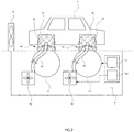
Fig. 1 andFig. 2 , a chassis dynamo device that is thevehicle testing device 100 according to the present embodiment includes, for example, achassis dynamometer 1 on which a test vehicle that is a test piece is mounted, avehicle fixing part 2 that fixes the test vehicle V to the chassis dynamometer, and adynamo controller 3 that controls thechassis dynamometer 1. - The
chassis dynamometer 1 functions as, for example, a load device that applies load to the test vehicle V in accordance with a driving state in mode running or actual road running. - Specifically, the
chassis dynamometer 1 includes, for example,rollers 11 that are rotating bodies on which drive wheels, such as front wheels, of tire-wheel assemblies W of the test vehicle V are placed, a power absorber connected to therollers 11, and alarge fan 12 disposed ahead of the test vehicle V. - The rotating bodies are, for example,
cylindrical rollers 11, endless belts, or the like configured to rotate in a front-rear direction of the test vehicle V. - The
vehicle fixing part 2 includes, for example,rails 21 extending in the front-rear direction of the test vehicle V,poles 22 installed so as to be movable along therails 21,wires 23 that connect thepoles 22 to the test vehicle V, and the like. - The
rails 21 are, for example, disposed on both sides of the test vehicle V so as to be parallel to the front-rear direction of the test vehicle V. - The
dynamo controller 3 is configured such that an information processing circuit including, for example, a CPU, memory, an A/D converter, a D/A converter, and the like causes the CPU and peripheral devices to cooperate in accordance with a program stored in a predetermined area of the memory to exercise the function. - The
dynamo controller 3 controls the torque of the power absorber such that a target running resistance determined in a predetermined running mode is attained. - Thus, the
chassis dynamo device 100 according to the present embodiment further includes cooling devices 4 that cool drive wheels and non-drive wheels that are the tire-wheel assemblies W of the test vehicle V, brakes B installed in these tire-wheel assemblies W, or the like with air. - Each cooling device 4 includes a
fan 41 for generating air flow, ablower tube 43 of which one end is connected to thefan 41 and the other end has anair outlet 42, a wind direction adjuster 44 that adjusts a position and/or an orientation of theair outlet 42 relative to the test vehicle V, and anair volume controller 45 that controls the volume of air. - The number of the cooling devices 4 provided is equal to the number of the tire-wheel assemblies W of the test vehicle V placed on the
chassis dynamo device 100. - The
fan 41 is disposed in, for example, an underground pit G of thechassis dynamo device 100 or outside therail 21. - The
blower tube 43 is a flexible hose that connects thefan 41 and theair outlet 42. - In this embodiment, a distal end portion of the
blower tube 43 where theair outlet 42 is formed is made up of a nozzle member, and is disposed on the side of theroller 11 outside aguard fence 24 provided outside the tire-wheel assembly so that air is sent to the side of the tire-wheel assembly W from outside theguard fence 24. Theair outlet 42 has a circular shape with a diameter of about 5 cm. - The
wind direction adjuster 44 adjusts the position and/or the orientation of theair outlet 42 by changing the position and/or the orientation of the distal end portion of theblower tube 43 attached to thewind direction adjuster 44. - As illustrated in
Fig. 3 , thewind direction adjuster 44 includes aposition adjustment mechanism 441 that adjusts the position of the distal end portion in the front-rear direction of the test vehicle V and anorientation adjustment mechanism 442 that adjusts the orientation of the distal end portion in the front-rear direction of the test vehicle V. - In the present embodiment, the
position adjustment mechanism 441 includes a firstposition adjustment mechanism 441a capable of roughly moving the position of the distal end portion and a secondposition adjustment mechanism 441b capable of minutely adjusting the position of the distal end portion. - The first
position adjustment mechanism 441a is made up of the pair ofrails 21 of thechassis dynamo device 100, and a movable base a1 slidable along therails 21. - The movable base a1 is adjusted to a predetermined position and then fixed by a first fixing mechanism a2, such as a screw. In the drawings, the movable base a1 is illustrated as a rectangular frame member; however, the movable base a1 is not limited thereto.
- The second
position adjustment mechanism 441b includes a pair of rails b1 provided for the movable base a1, and a slide member b2 slidable on the rails b1 of the movable base a1. - The slide member b2 is adjusted to a predetermined position and then fixed by a second fixing mechanism b3, such as a screw. In the drawings, the slide member b2 is a rectangular plate having a smaller size in the front-rear direction of the test vehicle V than the movable base a1; however, the slide member b2 is not limited thereto.
- In this embodiment, the second
position adjustment mechanism 441b is provided so as to be interposed between the movable base a1 and the distal end portion attached to the movable base a1. - In this embodiment, the
orientation adjustment mechanism 442 is provided so as to be further interposed between the slide member b2 and the distal end portion attached to the slide member b2. - The
orientation adjustment mechanism 442 includes aturn member 442a to which the distal end portion is fixed, and a support member 442b that supports theturn member 442a such that theturn member 442a is able to turn. - In the present embodiment, the
turn member 442a is, for example, a disk-shaped plate and is configured to be capable of turning 45° each, 90° in total, in forward and rearward directions of the test vehicle V by turning while its outer periphery is in contact with the inner periphery of the support member 442b. - The
turn member 442a is fixed by, for example, anorientation fixing mechanism 442c, such as a crank lever. - In this embodiment, the support member 442b is the slide member b2, and the
turn member 442a is accommodated in a recessed portion b21 formed on the surface of the slide member b2 such that the outer periphery of theturn member 442a comes in contact with the inner periphery of the recessed portion. - An example of a method of adjusting the position or the orientation of the
air outlet 42 by thewind direction adjuster 44 will be described below. - The position of the
air outlet 42 can be adjusted by changing the position, in the front-rear direction of the test vehicle V, of the movable base a1 or the slide member b2, to which the distal end portion of theblower tube 43 is attached. - The position of the movable base a1 is changed by moving the movable base a1 along the
rails 21 after loosening the screw that is the first fixing mechanism a2 and then fixing the movable base a1 to therails 21 at a desired position by fastening the screw that is the first fixing mechanism a2. - When the position of the movable base a1 is changed in this way, the positions of the second
position adjustment mechanism 441b and theorientation adjustment mechanism 442, mounted on the movable base a1, are also changed accordingly. - The position of the slide member b2 is changed by loosening the screw that is the second fixing mechanism b3 that fixes the slide member b2 to the rails b1 provided for the movable base a1 and then sliding the slide member b2 in the front-rear direction of the test vehicle V on the rails b1 of the movable base a1. After the slide member b2 is moved to a desired position, the slide member b2 is fixed to the rails b1 of the movable base a1 by fastening the screw that is the second fixing mechanism b3.
- When the position of the slide member b2 is changed in this way, the position of the
orientation adjustment mechanism 442 mounted on the slide member b2 is also changed accordingly. - The orientation of the
air outlet 42 can be adjusted by the degree of turn, in the front-rear direction of the test vehicle V, of theturn member 442a to which the distal end portion of theblower tube 43 is fixed. - In this embodiment, the degree of turn of the
turn member 442a is changed by loosening theorientation fixing mechanism 442c that fixes theturn member 442a such that theturn member 442a does not turn relative to the slide member b2 and then turning theturn member 442a. When the orientation of theair outlet 42 becomes a desired angle, theorientation fixing mechanism 442c is fastened to fix theturn member 442a such that theturn member 442a does not turn relative to the slide member b2. - In this way, by adjusting the position and/or the orientation of the
air outlet 42, it is possible to send air from theair outlet 42 toward an intended location, for example, a tire W1 of the tire-wheel assembly W, a wheel W2 of the tire-wheel assembly W, the brake B (a brake pad B1 or a brake disk B2), a wheel accommodation space W4 (tire house) provided between a body of the test vehicle V and the tire-wheel assembly W. -
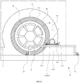
Fig. 4 is a diagram illustrating an example of a positional relationship between a part to be cooled and the air outlet in the case where air is blown to the wheel accommodation space W4.Fig. 5 is a diagram illustrating an example of a positional relationship between a part to be cooled and the air outlet in the case where air is blown to the brake pad or the brake disk. - For the position of the
air outlet 42 in the front-rear direction of the test vehicle V, for example, as illustrated inFig. 6 , air can be sent from diagonally ahead of the test vehicle V by disposing theair outlet 42 on the front side of the test vehicle V with respect to the center of the tire-wheel assembly W that receives air from theair outlet 42. - The
air volume controller 45 is the one that the information processing circuit exercises the function and controls a volume of air by, for example, controlling the number of revolutions of thefan 41. - A method of controlling the volume of air by the
air volume controller 45 will be described below with reference toFig. 7 . - The
air volume controller 45 controls, for example, the number of revolutions of thefan 41 in accordance with, for example, a signal indicating a torque-related value or the like from thetorque sensor 31 or thedynamo controller 3, or a signal from a detector, such as aspeed sensor 5 that detects the vehicle speed of the test vehicle V or the rotational speed of theroller 11 and a temperature sensor 6 that detects a temperature or the like of the tire-wheel assembly W. - When the tire-wheel assembly W of the test vehicle V is cooled, it is conceivable that heat due to friction between the
roller 11 and the tire-wheel assembly W is likely to be generated as the vehicle speed of the test vehicle V or the rotational speed of theroller 11 increases. - For this reason, when the
air volume controller 45 controls the volume of air sent from theair outlet 42 in accordance with the vehicle speed of the test vehicle V or the rotational speed of theroller 11, it is possible to further appropriately cool the tire-wheel assembly W by preventing excessive cooling and insufficient cooling. - The
air volume controller 45 controls the volume of air such that the volume of air increases as the vehicle speed of the test vehicle V or the rotational speed of theroller 11 increases, so that it is also possible to improve the reproducibility of load caused by air from the side in actual road running. - The
air volume controller 45 may control the volume of air such that the volume of air increases as the temperature of the tire-wheel assembly W increases. - With this configuration, it is possible to further appropriately cool the tire-wheel assembly W by preventing excessive cooling and insufficient cooling of the tire-wheel assembly W.
- Depending on test conditions, not only the tire-wheel assembly W but also the brake B installed in the tire-wheel assembly W may be intended to be cooled.
- This is because, particularly, in the case of a continuous downhill, it is conceivable that large friction generated between the brake B and the tire-wheel assembly W continues for a long time and, therefore, excessive heat accumulates in the brake B.
- In the invention of the subject application, air is blown from the side of the test vehicle V, so it is possible to blow air at the brake pad B1 or the brake disk B2, which is a component of the brake B. Therefore, it is possible to suppress excessive heat accumulated in the brake pad B1 or the brake disk B2.
- In such a case, it is also conceivable that the
air volume controller 45 controls the volume of air such that the volume of air is increased as the deceleration of the vehicle speed of the test piece or the deceleration of the rotational speed of theroller 11 increases. - When large friction is generated between the brake B and the tire-wheel assembly W, the brake B needs to be cooled; whereas, when friction is sufficiently small or when the vehicle speed of the test piece or the rotational speed of the
roller 11 is decelerating not by the brake B but by engine braking or the like, the necessity to cool the brake B decreases. - Therefore, the
air volume controller 45 obtains friction to such an extent that cooling is not needed or the deceleration of the vehicle speed of the test piece or the deceleration of the rotational speed of theroller 11, caused by the engine brake or the like, as a predetermined threshold in advance and, only when the deceleration becomes greater than or equal to the threshold, increases the volume of air. With this configuration, it is possible to further efficiently cool the brake B. - Incidentally, it is conceivable that, depending on the angle of the
air outlet 42 relative to the front-rear direction of the test vehicle V, the way in which air blows against the tire-wheel assembly W, the wheel accommodation space W4, the brake B, or the like and the cooling efficiency change. - Therefore, the
air volume controller 45 may control the volume of air in accordance with a signal from a wind direction sensor 7 that detects the angle of theair outlet 42 or air sent from theair outlet 42 relative to the front-rear direction of the test vehicle V. - With the thus configured
chassis dynamo device 100, the following advantageous effects are obtained. - Air from the
air outlet 42 is blown from the side of the tire-wheel assembly W against the tire-wheel assembly W or the wheel accommodation space W4, and furthermore thewind direction adjuster 44 that adjusts the position or the orientation of theair outlet 42 is provided, so it is possible to directly send air also to the side surface of the tire W1, the wheel W2, the brake pad B1, the brake disk B2, or the like, to which air has not been able to be directly blown before. - As a result, it is possible to freely select a part of the test vehicle V to be cooled and a wind direction in accordance with a purpose of a test.
- Air from the
air outlet 42 is blown from the side of the tire-wheel assembly W against the tire-wheel assembly W or the wheel accommodation space W4, so it is possible to circulate air in the wheel accommodation space W4, with the result that it is possible to efficiently cool the entire tire-wheel assembly W as compared to before. - It is conceivable that, on a road, there is the influence of not only wind from ahead but also wind from a side. Therefore, in a test that reproduces actual road running indoors, it is possible to reproduce wind from the side of the test vehicle V, so it is presumable that a test is possible under conditions further close to actual running conditions.
- Since the shape of the distal end portion of the
blower tube 43 is formed in a nozzle shape and the diameter of theair outlet 42 formed at the distal end portion is small and set to about 5 cm, it is possible to blow air against the test vehicle V at an wind velocity of about 200 km/h even when an especiallylarge fan 41 is not prepared. - Since the movable base a1 of the
wind direction adjuster 44 is installed on therails 21 originally provided for thechassis dynamo device 100 and then the position of theair outlet 42 is adjusted, it is possible to change the position of theair outlet 42 in the front-rear direction of the test vehicle V with a simple configuration. - The
rails 21 are sufficiently longer than the front-rear length of the test vehicle V, so it is possible to move the position of theair outlet 42 in the front-rear direction of the test vehicle V within a range wider than the front-rear length of the test vehicle V. - Specifically, it is possible to blow air from the
air outlet 42 at the tire part W1 of the tire-wheel assembly W, the wheel part W2 of the tire-wheel assembly W, the brake pad B1 or the brake disk B2 installed in the tire-wheel assembly W, the wheel accommodation space W4 accommodating the tire-wheel assembly W, or the like. The angle of air blown against each part may also be freely adjusted. - Particularly, when air from the
air outlet 42 is configured to be blown from diagonally ahead against the tire-wheel assembly W, it is possible to faithfully reproduce running conditions on an actual road. - Since it is also possible to blow air against a contact area of the tire-wheel assembly W, it is possible to further efficiently cool the tire-wheel assembly W.
- Since the
wind direction adjuster 44 includes theposition adjustment mechanism 441 and theorientation adjustment mechanism 442, it is possible to further flexibly change the position and/or the orientation of theair outlet 42 by simple operation. - Furthermore, when the position or angle of the
air outlet 42 is slightly changed, it is possible to simply change the position and/or the orientation of theair outlet 42 only by individually adjusting the slide member b2 or theturn member 442a without moving the movable base a1. - Since the
fan 41 and theair outlet 42 are connected by theblower tube 43, it is possible to freely select the location where thefan 41 is installed. - More specifically, it is not necessary to dispose the
fan 41 around the test vehicle V, and thefan 41 may be disposed in, for example, an underground pit, so space is saved. - The present invention is not limited to the above embodiment.
- For example, the configuration is not limited to the one in which each cooling device 4 provided for a corresponding one of the
rollers 11 of the chassis dynamo device includes thesingle fan 41. A plurality of cooling devices 4 may share thefan 41, or a single cooling device 4 may include a plurality offans 41. - The cooling device 4 is not limited to the one including the
single blower tube 43. The cooling device 4 may include a plurality ofblower tubes 43. Two ormore air outlets 42, such as, for example, theair outlet 42 that sends air to the brake pad B1, theair outlet 42 that sends air to the wheel accommodation space W4, and the like, may be provided for the single tire-wheel assembly W. - The diameter and shape of the
air outlet 42 may be changed as needed in accordance with the size of thefan 41, a purpose of a test, a part to be cooled, or the like. - The
air outlet 42 may be formed at the distal end of theblower tube 43. Alternatively, when there is space for placing thefan 41, theair outlet 42 may be directly formed in a casing of thefan 41 disposed outside theguard fence 24. - The
air outlet 42 may be disposed inside theguard fence 24. A chassis dynamo device that does not include theguard fence 24 may be provided. - The
position adjustment mechanism 441 and theorientation adjustment mechanism 442 of thewind direction adjuster 44 are not limited to the above-described ones. Theposition adjustment mechanism 441 may be interposed between theorientation adjustment mechanism 442 and the distal end portion of theblower tube 43 attached to theorientation adjustment mechanism 442. - The
position adjustment mechanism 441 is not limited to the one including the firstposition adjustment mechanism 441a and the secondposition adjustment mechanism 441b. Theposition adjustment mechanism 441 may be configured to be capable of adjusting the position of theair outlet 42 in further larger number of steps or may include only the firstposition adjustment mechanism 441a. - In the above embodiment, the rails b1 are provided for the movable base a1 of the
position adjustment mechanism 441, and the slide member b2 slides on the rails b1. Alternatively, the rails b1 may be provided for the slide member b2, and the movable base a1 may slide relative to the slide member b2. - The
orientation adjustment mechanism 442 just needs to turn such that the outer periphery or inner periphery of theturn member 442a is in contact with the outer periphery or inner periphery of the support member 442b. Theorientation adjustment mechanism 442 may include, for example, a shaft member integrally formed with the slide member b2, and a shaft hole formed in theturn member 442a. - The shaft member and the shaft hole may be formed in any one of the slide member b2 and the
turn member 442a. - The vehicle fixing part just needs to include the
rails 21, and thepoles 22 and thewires 23 may be other vehicle fixing members. - For control over the volume of air, a table may be prepared in advance in accordance with conditions of a test, and the
air volume controller 45 may control the volume of air in accordance with the conditions recorded in the table. - Not using the
air volume controller 45, a user may manually set the volume of air. - The
air volume controller 45 is not limited to the one that controls the number of revolutions of thefan 41 as described above. Theair volume controller 45 may control the opening degree of a valve that is provided inside theblower tube 43 and that adjusts the flow rate of air flowing through theblower tube 43 or may control the diameter or the like of theair outlet 42. - Other than the above, without departing from the purport of the present invention, various modifications and a combination of embodiments are applicable.
- According to the present invention, it is possible to freely select a part of a test piece to be cooled and a wind direction in accordance with a purpose of a test, and it is also possible to improve cooling efficiency for parts to be cooled as compared to before.
Claims (13)
- A vehicle testing device that tests a test piece that is a vehicle or a part of the vehicle, the vehicle testing device comprising:a rotating body on which the test piece is placed; anda cooling device that sends air from a side of the rotating body toward at least a part of the test piece in order to cool the test piece placed on the rotating body.
- The vehicle testing device according to Claim 1, wherein the cooling device includes
an air outlet through which air is sent from the side of the rotating body toward at least a part of the test piece, and
a wind direction adjuster that adjusts a position or an orientation of the air outlet. - The vehicle testing device according to Claim 2, wherein the wind direction adjuster is configured to be movable in a front-rear direction of the test piece on the side of the rotating body.
- The vehicle testing device according to Claim 2 or 3, further comprising:a vehicle fixing part disposed on the side of the rotating body so as to extend in a front-rear direction of the test piece and used to fix the test piece on the rotating body, whereinthe wind direction adjuster is fixed to the vehicle fixing part.
- The vehicle testing device according to Claim 4, wherein the wind direction adjuster is fixed to the vehicle fixing part such that the position of the air outlet is movable relative to the test piece along a direction in which the vehicle fixing part extends.
- The vehicle testing device according to any one of Claims 2 to 5, wherein the wind direction adjuster adjusts the position or the orientation of the air outlet such that air is sent toward a tire-wheel assembly of the test piece or a wheel accommodation space accommodating the tire-wheel assembly of the test piece.
- The vehicle testing device according to any one of Claims 2 to 6, wherein the wind direction adjuster causes the air outlet to be turnable in a front-rear direction of the test piece.
- The vehicle testing device according to any one of Claims 2 to 7, further comprising an air volume controller that controls a volume of air sent from the air outlet.
- The vehicle testing device according to Claim 8, wherein the air volume controller controls the volume of air in accordance with a vehicle speed of the test piece, a rotational speed of the tire-wheel assembly, or a temperature of the tire-wheel assembly.
- The vehicle testing device according to Claim 8 or 9, wherein the air volume controller controls the volume of air in accordance with a deceleration of a vehicle speed of the test piece or a deceleration of a rotational speed of the tire-wheel assembly.
- The vehicle testing device according to Claim 10, wherein, when the deceleration is greater than or equal to a predetermined threshold, the air volume controller controls the volume of air such that the volume of air increases.
- A cooling device that cools at least a part of a test piece that is a vehicle placed on a rotating body or a part of the vehicle, the cooling device comprising:an air outlet that is disposed on a side of the rotating body and that sends air toward at least a part of the test piece placed on the rotating body; anda wind direction adjuster that adjusts a position or an orientation of the air outlet.
- A cooling method for cooling at least a part of a test piece that is a vehicle placed on a rotating body or a part of the vehicle, the cooling method comprising:
sending air from a side of the rotating body to at least a part of the test piece in order to cool the test piece placed on the rotating body on which the test piece is placed.
Applications Claiming Priority (2)
| Application Number | Priority Date | Filing Date | Title |
|---|---|---|---|
| JP2018135371 | 2018-07-18 | ||
| PCT/JP2019/027860 WO2020017485A1 (en) | 2018-07-18 | 2019-07-16 | Vehicle testing device |
Publications (3)
| Publication Number | Publication Date |
|---|---|
| EP3825675A1 true EP3825675A1 (en) | 2021-05-26 |
| EP3825675A4 EP3825675A4 (en) | 2022-05-04 |
| EP3825675B1 EP3825675B1 (en) | 2024-01-10 |
Family
ID=69164684
Family Applications (1)
| Application Number | Title | Priority Date | Filing Date |
|---|---|---|---|
| EP19838685.6A Active EP3825675B1 (en) | 2018-07-18 | 2019-07-16 | Vehicle testing device |
Country Status (4)
| Country | Link |
|---|---|
| US (1) | US11519823B2 (en) |
| EP (1) | EP3825675B1 (en) |
| JP (1) | JP7324201B2 (en) |
| WO (1) | WO2020017485A1 (en) |
Cited By (1)
| Publication number | Priority date | Publication date | Assignee | Title |
|---|---|---|---|---|
| CN113237668A (en) * | 2021-03-31 | 2021-08-10 | 湖北环一电磁装备工程技术有限公司 | Environmental test chamber for simulating multi-environment system of heavy-load chassis dynamometer |
Families Citing this family (3)
| Publication number | Priority date | Publication date | Assignee | Title |
|---|---|---|---|---|
| CN111122178B (en) * | 2020-03-24 | 2021-08-17 | 王涛 | Axle type chassis dynamometer for vehicle |
| WO2022250042A1 (en) * | 2021-05-25 | 2022-12-01 | 株式会社堀場製作所 | Test object testing system, travel resistance calculation device, travel resistance calculation program, and test object testing method |
| CN115144204B (en) * | 2022-06-29 | 2025-06-17 | 东风汽车集团股份有限公司 | A K&C test tool and method for testing vehicles equipped with hot melt tires |
Family Cites Families (9)
| Publication number | Priority date | Publication date | Assignee | Title |
|---|---|---|---|---|
| JPH0643940B2 (en) * | 1985-08-28 | 1994-06-08 | 株式会社明電舍 | Breaker tester control device |
| JP3109396B2 (en) | 1994-05-25 | 2000-11-13 | トヨタ自動車株式会社 | Vehicle restraint |
| KR100337298B1 (en) * | 2000-04-03 | 2002-05-17 | 이계안 | Tire cooling system for chassis dynamo meter |
| JP2001289741A (en) | 2000-04-10 | 2001-10-19 | Toyo Eng Works Ltd | Traveling test apparatus for test self-advancing vehicle |
| EP1338881A1 (en) | 2002-02-21 | 2003-08-27 | European Community | Chassis dynamometer for testing a vehicle in a wind tunnel |
| JP2009133631A (en) | 2007-11-28 | 2009-06-18 | Bridgestone Corp | Durability test method of tire drum |
| BRPI1010706A2 (en) | 2009-06-12 | 2016-03-15 | Sumitomo Rubber Ind | vehicle |
| JP6027184B2 (en) | 2014-05-20 | 2016-11-16 | 公益財団法人日本自動車輸送技術協会 | Tire cooling control system for chassis dynamometer |
| CZ27656U1 (en) | 2014-08-27 | 2014-12-29 | Atal Spol.S R.O. | Roller test stand for motor vehicles |
-
2019
- 2019-07-16 JP JP2020531307A patent/JP7324201B2/en active Active
- 2019-07-16 EP EP19838685.6A patent/EP3825675B1/en active Active
- 2019-07-16 WO PCT/JP2019/027860 patent/WO2020017485A1/en not_active Ceased
- 2019-07-16 US US17/059,396 patent/US11519823B2/en active Active
Cited By (1)
| Publication number | Priority date | Publication date | Assignee | Title |
|---|---|---|---|---|
| CN113237668A (en) * | 2021-03-31 | 2021-08-10 | 湖北环一电磁装备工程技术有限公司 | Environmental test chamber for simulating multi-environment system of heavy-load chassis dynamometer |
Also Published As
| Publication number | Publication date |
|---|---|
| WO2020017485A1 (en) | 2020-01-23 |
| EP3825675A4 (en) | 2022-05-04 |
| US20210239572A1 (en) | 2021-08-05 |
| EP3825675B1 (en) | 2024-01-10 |
| US11519823B2 (en) | 2022-12-06 |
| JP7324201B2 (en) | 2023-08-09 |
| JPWO2020017485A1 (en) | 2021-08-02 |
Similar Documents
| Publication | Publication Date | Title |
|---|---|---|
| EP3825675B1 (en) | Vehicle testing device | |
| US20200017145A1 (en) | Chassis with wheels | |
| CN104742640A (en) | Anti-drag device capable of adjusting wheel spoke hole area automatically | |
| JP2008201156A (en) | Vehicle rectifier | |
| JP6022105B2 (en) | Automatic vehicle power generator | |
| JP2011240882A (en) | In-wheel motor cooling structure | |
| KR20160111704A (en) | Exercise Apparatus Having Slope Realizing Function with Bicycle | |
| JP2017039481A (en) | Electric power converter and railway vehicle | |
| US9516703B1 (en) | Magnetic heat generation and transfer assembly | |
| ES1143058U (en) | TEST BENCH FOR MOTOR VEHICLES | |
| CN209085516U (en) | A new energy vehicle air conditioning clutch plate flatness detection device | |
| NL2019305B1 (en) | Dual tyre rim | |
| CN117215391A (en) | Cooling system and server | |
| CN204578293U (en) | Turbine cooling system | |
| JP2561010Y2 (en) | High temperature environment test equipment | |
| CN105531912A (en) | Cooling of machines for elevator systems | |
| CN116085104B (en) | Cooling fan control strategies, devices, equipment, media and vehicles | |
| JP2012016996A5 (en) | ||
| JP2021069144A (en) | Torque control apparatus | |
| KR101383443B1 (en) | Cooling system for chassis dynamometer and control method thereof | |
| JP2002174566A (en) | Chassis dynamometer for motorcycles | |
| JP2008238855A (en) | Cooling device of automobile | |
| KR100337298B1 (en) | Tire cooling system for chassis dynamo meter | |
| CN223565254U (en) | Thermal balance performance detection device for motorcycle water cooling system | |
| KR20220038812A (en) | Camera arrangement for mounting on a vehicle |
Legal Events
| Date | Code | Title | Description |
|---|---|---|---|
| STAA | Information on the status of an ep patent application or granted ep patent |
Free format text: STATUS: THE INTERNATIONAL PUBLICATION HAS BEEN MADE |
|
| PUAI | Public reference made under article 153(3) epc to a published international application that has entered the european phase |
Free format text: ORIGINAL CODE: 0009012 |
|
| STAA | Information on the status of an ep patent application or granted ep patent |
Free format text: STATUS: REQUEST FOR EXAMINATION WAS MADE |
|
| 17P | Request for examination filed |
Effective date: 20201126 |
|
| AK | Designated contracting states |
Kind code of ref document: A1 Designated state(s): AL AT BE BG CH CY CZ DE DK EE ES FI FR GB GR HR HU IE IS IT LI LT LU LV MC MK MT NL NO PL PT RO RS SE SI SK SM TR |
|
| DAV | Request for validation of the european patent (deleted) | ||
| DAX | Request for extension of the european patent (deleted) | ||
| RAP3 | Party data changed (applicant data changed or rights of an application transferred) |
Owner name: HORIBA, LTD. |
|
| RIN1 | Information on inventor provided before grant (corrected) |
Inventor name: ZHANG, DONGKAI Inventor name: ADACHI, KAORI Inventor name: NAGAYAMA, TAKASHI |
|
| A4 | Supplementary search report drawn up and despatched |
Effective date: 20220407 |
|
| RIC1 | Information provided on ipc code assigned before grant |
Ipc: B60C 19/00 20060101ALI20220401BHEP Ipc: G01M 17/007 20060101AFI20220401BHEP |
|
| STAA | Information on the status of an ep patent application or granted ep patent |
Free format text: STATUS: EXAMINATION IS IN PROGRESS |
|
| 17Q | First examination report despatched |
Effective date: 20230330 |
|
| GRAP | Despatch of communication of intention to grant a patent |
Free format text: ORIGINAL CODE: EPIDOSNIGR1 |
|
| STAA | Information on the status of an ep patent application or granted ep patent |
Free format text: STATUS: GRANT OF PATENT IS INTENDED |
|
| INTG | Intention to grant announced |
Effective date: 20230905 |
|
| GRAS | Grant fee paid |
Free format text: ORIGINAL CODE: EPIDOSNIGR3 |
|
| GRAA | (expected) grant |
Free format text: ORIGINAL CODE: 0009210 |
|
| STAA | Information on the status of an ep patent application or granted ep patent |
Free format text: STATUS: THE PATENT HAS BEEN GRANTED |
|
| P01 | Opt-out of the competence of the unified patent court (upc) registered |
Effective date: 20231108 |
|
| AK | Designated contracting states |
Kind code of ref document: B1 Designated state(s): AL AT BE BG CH CY CZ DE DK EE ES FI FR GB GR HR HU IE IS IT LI LT LU LV MC MK MT NL NO PL PT RO RS SE SI SK SM TR |
|
| REG | Reference to a national code |
Ref country code: GB Ref legal event code: FG4D |
|
| REG | Reference to a national code |
Ref country code: CH Ref legal event code: EP |
|
| REG | Reference to a national code |
Ref country code: DE Ref legal event code: R096 Ref document number: 602019045012 Country of ref document: DE |
|
| REG | Reference to a national code |
Ref country code: IE Ref legal event code: FG4D |
|
| REG | Reference to a national code |
Ref country code: LT Ref legal event code: MG9D |
|
| REG | Reference to a national code |
Ref country code: NL Ref legal event code: MP Effective date: 20240110 |
|
| REG | Reference to a national code |
Ref country code: AT Ref legal event code: MK05 Ref document number: 1649262 Country of ref document: AT Kind code of ref document: T Effective date: 20240110 |
|
| PG25 | Lapsed in a contracting state [announced via postgrant information from national office to epo] |
Ref country code: NL Free format text: LAPSE BECAUSE OF FAILURE TO SUBMIT A TRANSLATION OF THE DESCRIPTION OR TO PAY THE FEE WITHIN THE PRESCRIBED TIME-LIMIT Effective date: 20240110 |
|
| PG25 | Lapsed in a contracting state [announced via postgrant information from national office to epo] |
Ref country code: NL Free format text: LAPSE BECAUSE OF FAILURE TO SUBMIT A TRANSLATION OF THE DESCRIPTION OR TO PAY THE FEE WITHIN THE PRESCRIBED TIME-LIMIT Effective date: 20240110 |
|
| PG25 | Lapsed in a contracting state [announced via postgrant information from national office to epo] |
Ref country code: IS Free format text: LAPSE BECAUSE OF FAILURE TO SUBMIT A TRANSLATION OF THE DESCRIPTION OR TO PAY THE FEE WITHIN THE PRESCRIBED TIME-LIMIT Effective date: 20240510 |
|
| PG25 | Lapsed in a contracting state [announced via postgrant information from national office to epo] |
Ref country code: LT Free format text: LAPSE BECAUSE OF FAILURE TO SUBMIT A TRANSLATION OF THE DESCRIPTION OR TO PAY THE FEE WITHIN THE PRESCRIBED TIME-LIMIT Effective date: 20240110 |
|
| PG25 | Lapsed in a contracting state [announced via postgrant information from national office to epo] |
Ref country code: GR Free format text: LAPSE BECAUSE OF FAILURE TO SUBMIT A TRANSLATION OF THE DESCRIPTION OR TO PAY THE FEE WITHIN THE PRESCRIBED TIME-LIMIT Effective date: 20240411 |
|
| PG25 | Lapsed in a contracting state [announced via postgrant information from national office to epo] |
Ref country code: HR Free format text: LAPSE BECAUSE OF FAILURE TO SUBMIT A TRANSLATION OF THE DESCRIPTION OR TO PAY THE FEE WITHIN THE PRESCRIBED TIME-LIMIT Effective date: 20240110 Ref country code: RS Free format text: LAPSE BECAUSE OF FAILURE TO SUBMIT A TRANSLATION OF THE DESCRIPTION OR TO PAY THE FEE WITHIN THE PRESCRIBED TIME-LIMIT Effective date: 20240410 |
|
| PG25 | Lapsed in a contracting state [announced via postgrant information from national office to epo] |
Ref country code: ES Free format text: LAPSE BECAUSE OF FAILURE TO SUBMIT A TRANSLATION OF THE DESCRIPTION OR TO PAY THE FEE WITHIN THE PRESCRIBED TIME-LIMIT Effective date: 20240110 |
|
| PG25 | Lapsed in a contracting state [announced via postgrant information from national office to epo] |
Ref country code: AT Free format text: LAPSE BECAUSE OF FAILURE TO SUBMIT A TRANSLATION OF THE DESCRIPTION OR TO PAY THE FEE WITHIN THE PRESCRIBED TIME-LIMIT Effective date: 20240110 |
|
| PG25 | Lapsed in a contracting state [announced via postgrant information from national office to epo] |
Ref country code: RS Free format text: LAPSE BECAUSE OF FAILURE TO SUBMIT A TRANSLATION OF THE DESCRIPTION OR TO PAY THE FEE WITHIN THE PRESCRIBED TIME-LIMIT Effective date: 20240410 Ref country code: NO Free format text: LAPSE BECAUSE OF FAILURE TO SUBMIT A TRANSLATION OF THE DESCRIPTION OR TO PAY THE FEE WITHIN THE PRESCRIBED TIME-LIMIT Effective date: 20240410 Ref country code: LT Free format text: LAPSE BECAUSE OF FAILURE TO SUBMIT A TRANSLATION OF THE DESCRIPTION OR TO PAY THE FEE WITHIN THE PRESCRIBED TIME-LIMIT Effective date: 20240110 Ref country code: IS Free format text: LAPSE BECAUSE OF FAILURE TO SUBMIT A TRANSLATION OF THE DESCRIPTION OR TO PAY THE FEE WITHIN THE PRESCRIBED TIME-LIMIT Effective date: 20240510 Ref country code: HR Free format text: LAPSE BECAUSE OF FAILURE TO SUBMIT A TRANSLATION OF THE DESCRIPTION OR TO PAY THE FEE WITHIN THE PRESCRIBED TIME-LIMIT Effective date: 20240110 Ref country code: GR Free format text: LAPSE BECAUSE OF FAILURE TO SUBMIT A TRANSLATION OF THE DESCRIPTION OR TO PAY THE FEE WITHIN THE PRESCRIBED TIME-LIMIT Effective date: 20240411 Ref country code: ES Free format text: LAPSE BECAUSE OF FAILURE TO SUBMIT A TRANSLATION OF THE DESCRIPTION OR TO PAY THE FEE WITHIN THE PRESCRIBED TIME-LIMIT Effective date: 20240110 Ref country code: BG Free format text: LAPSE BECAUSE OF FAILURE TO SUBMIT A TRANSLATION OF THE DESCRIPTION OR TO PAY THE FEE WITHIN THE PRESCRIBED TIME-LIMIT Effective date: 20240110 Ref country code: AT Free format text: LAPSE BECAUSE OF FAILURE TO SUBMIT A TRANSLATION OF THE DESCRIPTION OR TO PAY THE FEE WITHIN THE PRESCRIBED TIME-LIMIT Effective date: 20240110 |
|
| PG25 | Lapsed in a contracting state [announced via postgrant information from national office to epo] |
Ref country code: PT Free format text: LAPSE BECAUSE OF FAILURE TO SUBMIT A TRANSLATION OF THE DESCRIPTION OR TO PAY THE FEE WITHIN THE PRESCRIBED TIME-LIMIT Effective date: 20240510 Ref country code: PL Free format text: LAPSE BECAUSE OF FAILURE TO SUBMIT A TRANSLATION OF THE DESCRIPTION OR TO PAY THE FEE WITHIN THE PRESCRIBED TIME-LIMIT Effective date: 20240110 |
|
| PG25 | Lapsed in a contracting state [announced via postgrant information from national office to epo] |
Ref country code: SE Free format text: LAPSE BECAUSE OF FAILURE TO SUBMIT A TRANSLATION OF THE DESCRIPTION OR TO PAY THE FEE WITHIN THE PRESCRIBED TIME-LIMIT Effective date: 20240110 Ref country code: PT Free format text: LAPSE BECAUSE OF FAILURE TO SUBMIT A TRANSLATION OF THE DESCRIPTION OR TO PAY THE FEE WITHIN THE PRESCRIBED TIME-LIMIT Effective date: 20240510 Ref country code: PL Free format text: LAPSE BECAUSE OF FAILURE TO SUBMIT A TRANSLATION OF THE DESCRIPTION OR TO PAY THE FEE WITHIN THE PRESCRIBED TIME-LIMIT Effective date: 20240110 Ref country code: LV Free format text: LAPSE BECAUSE OF FAILURE TO SUBMIT A TRANSLATION OF THE DESCRIPTION OR TO PAY THE FEE WITHIN THE PRESCRIBED TIME-LIMIT Effective date: 20240110 |
|
| PG25 | Lapsed in a contracting state [announced via postgrant information from national office to epo] |
Ref country code: DK Free format text: LAPSE BECAUSE OF FAILURE TO SUBMIT A TRANSLATION OF THE DESCRIPTION OR TO PAY THE FEE WITHIN THE PRESCRIBED TIME-LIMIT Effective date: 20240110 |
|
| REG | Reference to a national code |
Ref country code: DE Ref legal event code: R097 Ref document number: 602019045012 Country of ref document: DE |
|
| PG25 | Lapsed in a contracting state [announced via postgrant information from national office to epo] |
Ref country code: SM Free format text: LAPSE BECAUSE OF FAILURE TO SUBMIT A TRANSLATION OF THE DESCRIPTION OR TO PAY THE FEE WITHIN THE PRESCRIBED TIME-LIMIT Effective date: 20240110 |
|
| PG25 | Lapsed in a contracting state [announced via postgrant information from national office to epo] |
Ref country code: CZ Free format text: LAPSE BECAUSE OF FAILURE TO SUBMIT A TRANSLATION OF THE DESCRIPTION OR TO PAY THE FEE WITHIN THE PRESCRIBED TIME-LIMIT Effective date: 20240110 Ref country code: EE Free format text: LAPSE BECAUSE OF FAILURE TO SUBMIT A TRANSLATION OF THE DESCRIPTION OR TO PAY THE FEE WITHIN THE PRESCRIBED TIME-LIMIT Effective date: 20240110 |
|
| PG25 | Lapsed in a contracting state [announced via postgrant information from national office to epo] |
Ref country code: SK Free format text: LAPSE BECAUSE OF FAILURE TO SUBMIT A TRANSLATION OF THE DESCRIPTION OR TO PAY THE FEE WITHIN THE PRESCRIBED TIME-LIMIT Effective date: 20240110 |
|
| PG25 | Lapsed in a contracting state [announced via postgrant information from national office to epo] |
Ref country code: SM Free format text: LAPSE BECAUSE OF FAILURE TO SUBMIT A TRANSLATION OF THE DESCRIPTION OR TO PAY THE FEE WITHIN THE PRESCRIBED TIME-LIMIT Effective date: 20240110 Ref country code: SK Free format text: LAPSE BECAUSE OF FAILURE TO SUBMIT A TRANSLATION OF THE DESCRIPTION OR TO PAY THE FEE WITHIN THE PRESCRIBED TIME-LIMIT Effective date: 20240110 Ref country code: RO Free format text: LAPSE BECAUSE OF FAILURE TO SUBMIT A TRANSLATION OF THE DESCRIPTION OR TO PAY THE FEE WITHIN THE PRESCRIBED TIME-LIMIT Effective date: 20240110 Ref country code: EE Free format text: LAPSE BECAUSE OF FAILURE TO SUBMIT A TRANSLATION OF THE DESCRIPTION OR TO PAY THE FEE WITHIN THE PRESCRIBED TIME-LIMIT Effective date: 20240110 Ref country code: DK Free format text: LAPSE BECAUSE OF FAILURE TO SUBMIT A TRANSLATION OF THE DESCRIPTION OR TO PAY THE FEE WITHIN THE PRESCRIBED TIME-LIMIT Effective date: 20240110 Ref country code: CZ Free format text: LAPSE BECAUSE OF FAILURE TO SUBMIT A TRANSLATION OF THE DESCRIPTION OR TO PAY THE FEE WITHIN THE PRESCRIBED TIME-LIMIT Effective date: 20240110 |
|
| PLBE | No opposition filed within time limit |
Free format text: ORIGINAL CODE: 0009261 |
|
| STAA | Information on the status of an ep patent application or granted ep patent |
Free format text: STATUS: NO OPPOSITION FILED WITHIN TIME LIMIT |
|
| PG25 | Lapsed in a contracting state [announced via postgrant information from national office to epo] |
Ref country code: IT Free format text: LAPSE BECAUSE OF FAILURE TO SUBMIT A TRANSLATION OF THE DESCRIPTION OR TO PAY THE FEE WITHIN THE PRESCRIBED TIME-LIMIT Effective date: 20240110 |
|
| 26N | No opposition filed |
Effective date: 20241011 |
|
| PG25 | Lapsed in a contracting state [announced via postgrant information from national office to epo] |
Ref country code: IT Free format text: LAPSE BECAUSE OF FAILURE TO SUBMIT A TRANSLATION OF THE DESCRIPTION OR TO PAY THE FEE WITHIN THE PRESCRIBED TIME-LIMIT Effective date: 20240110 |
|
| PG25 | Lapsed in a contracting state [announced via postgrant information from national office to epo] |
Ref country code: MC Free format text: LAPSE BECAUSE OF FAILURE TO SUBMIT A TRANSLATION OF THE DESCRIPTION OR TO PAY THE FEE WITHIN THE PRESCRIBED TIME-LIMIT Effective date: 20240110 |
|
| REG | Reference to a national code |
Ref country code: CH Ref legal event code: PL |
|
| PG25 | Lapsed in a contracting state [announced via postgrant information from national office to epo] |
Ref country code: LU Free format text: LAPSE BECAUSE OF NON-PAYMENT OF DUE FEES Effective date: 20240716 |
|
| PG25 | Lapsed in a contracting state [announced via postgrant information from national office to epo] |
Ref country code: LU Free format text: LAPSE BECAUSE OF NON-PAYMENT OF DUE FEES Effective date: 20240716 |
|
| PG25 | Lapsed in a contracting state [announced via postgrant information from national office to epo] |
Ref country code: CH Free format text: LAPSE BECAUSE OF NON-PAYMENT OF DUE FEES Effective date: 20240731 Ref country code: SI Free format text: LAPSE BECAUSE OF FAILURE TO SUBMIT A TRANSLATION OF THE DESCRIPTION OR TO PAY THE FEE WITHIN THE PRESCRIBED TIME-LIMIT Effective date: 20240110 Ref country code: BE Free format text: LAPSE BECAUSE OF NON-PAYMENT OF DUE FEES Effective date: 20240731 |
|
| PG25 | Lapsed in a contracting state [announced via postgrant information from national office to epo] |
Ref country code: FR Free format text: LAPSE BECAUSE OF NON-PAYMENT OF DUE FEES Effective date: 20240731 |
|
| REG | Reference to a national code |
Ref country code: BE Ref legal event code: MM Effective date: 20240731 |
|
| PGFP | Annual fee paid to national office [announced via postgrant information from national office to epo] |
Ref country code: GB Payment date: 20250529 Year of fee payment: 7 |
|
| PG25 | Lapsed in a contracting state [announced via postgrant information from national office to epo] |
Ref country code: IE Free format text: LAPSE BECAUSE OF NON-PAYMENT OF DUE FEES Effective date: 20240716 |
|
| PG25 | Lapsed in a contracting state [announced via postgrant information from national office to epo] |
Ref country code: FI Free format text: LAPSE BECAUSE OF FAILURE TO SUBMIT A TRANSLATION OF THE DESCRIPTION OR TO PAY THE FEE WITHIN THE PRESCRIBED TIME-LIMIT Effective date: 20240110 |
|
| PGFP | Annual fee paid to national office [announced via postgrant information from national office to epo] |
Ref country code: DE Payment date: 20250528 Year of fee payment: 7 |
|
| PG25 | Lapsed in a contracting state [announced via postgrant information from national office to epo] |
Ref country code: CY Free format text: LAPSE BECAUSE OF FAILURE TO SUBMIT A TRANSLATION OF THE DESCRIPTION OR TO PAY THE FEE WITHIN THE PRESCRIBED TIME-LIMIT; INVALID AB INITIO Effective date: 20190716 |
|
| PG25 | Lapsed in a contracting state [announced via postgrant information from national office to epo] |
Ref country code: HU Free format text: LAPSE BECAUSE OF FAILURE TO SUBMIT A TRANSLATION OF THE DESCRIPTION OR TO PAY THE FEE WITHIN THE PRESCRIBED TIME-LIMIT; INVALID AB INITIO Effective date: 20190716 |