EP3825622A1 - Heat pump water heater outdoor unit - Google Patents
Heat pump water heater outdoor unit Download PDFInfo
- Publication number
- EP3825622A1 EP3825622A1 EP18926577.0A EP18926577A EP3825622A1 EP 3825622 A1 EP3825622 A1 EP 3825622A1 EP 18926577 A EP18926577 A EP 18926577A EP 3825622 A1 EP3825622 A1 EP 3825622A1
- Authority
- EP
- European Patent Office
- Prior art keywords
- water
- heat
- outdoor unit
- pump hot
- water supply
- Prior art date
- Legal status (The legal status is an assumption and is not a legal conclusion. Google has not performed a legal analysis and makes no representation as to the accuracy of the status listed.)
- Granted
Links
Images


Classifications
-
- F—MECHANICAL ENGINEERING; LIGHTING; HEATING; WEAPONS; BLASTING
- F24—HEATING; RANGES; VENTILATING
- F24H—FLUID HEATERS, e.g. WATER OR AIR HEATERS, HAVING HEAT-GENERATING MEANS, e.g. HEAT PUMPS, IN GENERAL
- F24H4/00—Fluid heaters characterised by the use of heat pumps
- F24H4/02—Water heaters
-
- F—MECHANICAL ENGINEERING; LIGHTING; HEATING; WEAPONS; BLASTING
- F24—HEATING; RANGES; VENTILATING
- F24D—DOMESTIC- OR SPACE-HEATING SYSTEMS, e.g. CENTRAL HEATING SYSTEMS; DOMESTIC HOT-WATER SUPPLY SYSTEMS; ELEMENTS OR COMPONENTS THEREFOR
- F24D17/00—Domestic hot-water supply systems
- F24D17/02—Domestic hot-water supply systems using heat pumps
-
- F—MECHANICAL ENGINEERING; LIGHTING; HEATING; WEAPONS; BLASTING
- F24—HEATING; RANGES; VENTILATING
- F24D—DOMESTIC- OR SPACE-HEATING SYSTEMS, e.g. CENTRAL HEATING SYSTEMS; DOMESTIC HOT-WATER SUPPLY SYSTEMS; ELEMENTS OR COMPONENTS THEREFOR
- F24D19/00—Details
- F24D19/0097—Casings or frame structures for hydraulic components
-
- F—MECHANICAL ENGINEERING; LIGHTING; HEATING; WEAPONS; BLASTING
- F24—HEATING; RANGES; VENTILATING
- F24D—DOMESTIC- OR SPACE-HEATING SYSTEMS, e.g. CENTRAL HEATING SYSTEMS; DOMESTIC HOT-WATER SUPPLY SYSTEMS; ELEMENTS OR COMPONENTS THEREFOR
- F24D19/00—Details
- F24D19/08—Arrangements for drainage, venting or aerating
- F24D19/082—Arrangements for drainage, venting or aerating for water heating systems
- F24D19/088—Draining arrangements
-
- F—MECHANICAL ENGINEERING; LIGHTING; HEATING; WEAPONS; BLASTING
- F24—HEATING; RANGES; VENTILATING
- F24F—AIR-CONDITIONING; AIR-HUMIDIFICATION; VENTILATION; USE OF AIR CURRENTS FOR SCREENING
- F24F1/00—Room units for air-conditioning, e.g. separate or self-contained units or units receiving primary air from a central station
- F24F1/06—Separate outdoor units, e.g. outdoor unit to be linked to a separate room comprising a compressor and a heat exchanger
- F24F1/14—Heat exchangers specially adapted for separate outdoor units
- F24F1/16—Arrangement or mounting thereof
-
- F—MECHANICAL ENGINEERING; LIGHTING; HEATING; WEAPONS; BLASTING
- F24—HEATING; RANGES; VENTILATING
- F24F—AIR-CONDITIONING; AIR-HUMIDIFICATION; VENTILATION; USE OF AIR CURRENTS FOR SCREENING
- F24F1/00—Room units for air-conditioning, e.g. separate or self-contained units or units receiving primary air from a central station
- F24F1/06—Separate outdoor units, e.g. outdoor unit to be linked to a separate room comprising a compressor and a heat exchanger
- F24F1/36—Drip trays for outdoor units
-
- F—MECHANICAL ENGINEERING; LIGHTING; HEATING; WEAPONS; BLASTING
- F24—HEATING; RANGES; VENTILATING
- F24F—AIR-CONDITIONING; AIR-HUMIDIFICATION; VENTILATION; USE OF AIR CURRENTS FOR SCREENING
- F24F1/00—Room units for air-conditioning, e.g. separate or self-contained units or units receiving primary air from a central station
- F24F1/06—Separate outdoor units, e.g. outdoor unit to be linked to a separate room comprising a compressor and a heat exchanger
- F24F1/56—Casing or covers of separate outdoor units, e.g. fan guards
-
- F—MECHANICAL ENGINEERING; LIGHTING; HEATING; WEAPONS; BLASTING
- F24—HEATING; RANGES; VENTILATING
- F24H—FLUID HEATERS, e.g. WATER OR AIR HEATERS, HAVING HEAT-GENERATING MEANS, e.g. HEAT PUMPS, IN GENERAL
- F24H4/00—Fluid heaters characterised by the use of heat pumps
- F24H4/02—Water heaters
- F24H4/04—Storage heaters
-
- F—MECHANICAL ENGINEERING; LIGHTING; HEATING; WEAPONS; BLASTING
- F24—HEATING; RANGES; VENTILATING
- F24H—FLUID HEATERS, e.g. WATER OR AIR HEATERS, HAVING HEAT-GENERATING MEANS, e.g. HEAT PUMPS, IN GENERAL
- F24H9/00—Details
- F24H9/02—Casings; Cover lids; Ornamental panels
-
- F—MECHANICAL ENGINEERING; LIGHTING; HEATING; WEAPONS; BLASTING
- F24—HEATING; RANGES; VENTILATING
- F24D—DOMESTIC- OR SPACE-HEATING SYSTEMS, e.g. CENTRAL HEATING SYSTEMS; DOMESTIC HOT-WATER SUPPLY SYSTEMS; ELEMENTS OR COMPONENTS THEREFOR
- F24D2200/00—Heat sources or energy sources
- F24D2200/12—Heat pump
Definitions
- the present disclosure relates to a heat-pump hot-water supply outdoor unit having a water-refrigerant heat exchanger accommodated in a box-shaped heat insulator to reduce heat dissipation from the water-refrigerant heat exchanger to the outside.
- the heat-pump hot-water supply system includes a heat-pump hot-water supply outdoor unit.
- a heat-pump hot-water supply outdoor unit In the heat-pump hot-water supply outdoor unit, an evaporator configured to allow refrigerant to absorb heat in the atmosphere, a fan configured to deliver air to the evaporator, a compressor configured to compress the refrigerant, a water-refrigerant heat exchanger configured to heat water using the compressed high-temperature high-pressure refrigerant, and other devices are installed.
- the water-refrigerant heat exchanger is accommodated in a box-shaped heat insulator to reduce heat dissipation from the water-refrigerant heat exchanger to the outside during operation of the heat-pump hot-water supply outdoor unit.
- the water-refrigerant heat exchanger is accommodated in the box-shaped heat insulator, there is a possibility of corrosion of the water-refrigerant heat exchanger as described below. More specifically, when condensation occurs on the surface of the water-refrigerant heat exchanger, water on the surface of the water-refrigerant heat exchanger flows down and collects in an inner bottom portion of the heat insulator.
- the water-refrigerant heat exchanger When the water-refrigerant heat exchanger is immersed in the water collecting in the inner bottom portion of the heat insulator, there is a possibility of corrosion of the water-refrigerant heat exchanger. For this reason, it is desirable for the water-refrigerant heat exchanger not to be immersed in the water collecting in the inner bottom portion of the heat insulator.
- the inner bottom portion of the heat insulator is a bottom portion of the heat insulator on the inner side thereof.
- a related art heat-pump hot-water supply outdoor unit which is intended to prevent a water-refrigerant heat exchanger from being immersed in water collecting in an inner bottom portion of a heat insulator (see Patent Literature 1).
- a heat insulator configured to accommodate therein a water-refrigerant heat exchanger is made up of a lower heat insulator and an upper heat insulator.
- the lower heat insulator has an open top, and has a box shape elongated in the rightward-leftward direction.
- the upper heat insulator covers the open top of the lower heat insulator.
- the inner bottom portion of the lower heat insulator includes a flat portion.
- the water-refrigerant heat exchanger is placed on the flat portion.
- the inner bottom portion of the lower heat insulator is provided with a leaking-water discharge portion to prevent water from collecting in this inner bottom portion.
- This leaking-water discharge portion includes a through hole extending through the inner bottom portion of the lower heat insulator, and a filling sealing the through hole. According to Patent Literature 1, with this configuration, water having flowed down to the inner bottom portion of the lower heat insulator flows through the through hole while passing through or melting the filling, and is discharged to the outside of the heat insulator.
- Patent Literature 1 Japanese Unexamined Patent Application Publication No. 2015-45425
- the leaking-water discharge portion is provided in the flat portion of the inner bottom portion of the lower heat insulator.
- the water-refrigerant heat exchanger is placed on the flat portion. Due to this structure, when condensation occurs on the surface of the water-refrigerant heat exchanger, and then water on the surface of the water-refrigerant heat exchanger flows down to the flat portion of the inner bottom portion of the lower heat insulator, the water-refrigerant heat exchanger is immersed in the water for a while until the water is discharged from the leaking-water discharge portion.
- the present disclosure has been achieved to solve the above problems, and an object thereof is to provide a heat-pump hot-water supply outdoor unit that can significantly prevent a water-refrigerant heat exchanger accommodated in a box-shaped heat insulator from being immersed in water even when condensation occurs on the water-refrigerant heat exchanger, compared to the related-art heat-pump hot-water supply outdoor unit.
- a heat-pump hot-water supply outdoor unit includes: a box-shaped heat insulator; and a water-refrigerant heat exchanger accommodated in the heat insulator and configured to heat water with refrigerant, wherein an inner bottom portion of the heat insulator has an uneven shape with a protruding portion and a recessed portion, the recessed portion is formed with a drain hole extending through the inner bottom portion, and the water-refrigerant heat exchanger is placed on the protruding portion.
- a heat-pump hot-water supply outdoor unit when condensation occurs on the surface of a water-refrigerant heat exchanger, and then water on the surface of the water-refrigerant heat exchanger flows down to an inner bottom portion of a heat insulator, the water is collected in a recessed portion of the inner bottom portion. Thereafter, the water being collected in the recessed portion is discharged from a drain hole formed on the recessed portion to the outside of the heat insulator.
- the heat-pump hot-water supply outdoor unit can significantly prevent the water-refrigerant heat exchanger accommodated in a heat insulator with a box shape from being immersed in water even when condensation occurs on the water-refrigerant heat exchanger, compared to the related art heat-pump hot-water supply outdoor unit.
- heat-pump hot-water supply outdoor unit may include all combinations of configurations that can be combined among the configurations described in the following embodiment.
- Fig. 1 is a piping system diagram illustrating a heat-pump hot-water supply system including a heat-pump hot-water supply outdoor unit according to an embodiment of the present disclosure.
- a heat-pump hot-water supply system 90 includes a heat-pump hot-water supply outdoor unit 1 and a tank unit 91.
- the heat-pump hot-water supply outdoor unit 1 is located outdoors.
- the tank unit 91 may be either located outdoors or located indoors.
- the heat-pump hot-water supply outdoor unit 1 includes a compressor 2, a water-refrigerant heat exchanger 3, a first expansion valve 4a, a second expansion valve 4b, an evaporator 5, an internal heat exchanger 6, and a fan 7.
- the heat-pump hot-water supply outdoor unit 1 includes a refrigerant circuit and performs operation in a refrigeration cycle, that is, in a heat-pump cycle.
- the compressor 2 compresses low-pressure refrigerant.
- the refrigerant may be carbon dioxide.
- the water-refrigerant heat exchanger 3 includes a refrigerant pipe 3b and a water pipe 3a. High-temperature high-pressure refrigerant discharged from the compressor 2 flows through the refrigerant pipe 3b.
- the water-refrigerant heat exchanger 3 exchanges heat between high-temperature high-pressure refrigerant flowing through the refrigerant pipe 3b and water flowing through the water pipe 3a. That is, water flowing through the water pipe 3a is heated by high-temperature high-pressure refrigerant flowing through the refrigerant pipe 3b.
- the first expansion valve 4a and the second expansion valve 4b are examples of a pressure-reducing device configured to reduce the pressure of high-pressure refrigerant to obtain low-pressure refrigerant.
- the low-pressure refrigerant whose pressure has been reduced is brought into a two-phase gas-liquid state.
- the evaporator 5 is a heat exchanger configured to exchange heat between the low-pressure refrigerant and the atmosphere. In the evaporator 5, the low-pressure refrigerant absorbs heat in the atmosphere and evaporates.
- the fan 7 delivers air to the evaporator 5. This can help heat exchange in the evaporator 5.
- the internal heat exchanger 6 includes a high-pressure flow path and a low-pressure flow path.
- the internal heat exchanger 6 exchanges heat between high-pressure refrigerant flowing through the high-pressure flow path and low-pressure refrigerant flowing through the low-pressure flow path.
- the low-pressure refrigerant having evaporated in the evaporator 5 is absorbed into the compressor 2 via the low-pressure flow path of the internal heat exchanger 6.
- the tank unit 91 includes a water storage tank 92, a pump 93, a flow-path switching valve 94, and a bypass pipe 95.
- the heat-pump hot-water supply outdoor unit 1 and the tank unit 91 are connected to each other through an external pipe 96 and an external pipe 97.
- a hot-water feed pipe (not illustrated) is connected to supply hot water to terminals including, for example, a hot-water tap, a shower, and a bath.
- a water feed pipe (not illustrated) is connected to supply water from the source such as the tap.
- hot water in the top portion of the water storage tank 92 is delivered to the hot-water feed pipe by a water pressure acting on the interior of the water storage tank 92 from the water feed pipe.
- An equal amount of water to the amount of hot water having flowed out to the hot-water feed pipe flows into the water storage tank 92 from the water feed pipe, so that the water storage tank 92 is kept filled with water.
- the bottom portion of the water storage tank 92 connects to an inlet of the pump 93 through a conduit.
- An outlet of the pump 93 connects to the flow-path switching valve 94.
- the flow-path switching valve 94 connects to the water pipe 3a of the water-refrigerant heat exchanger 3 in the heat-pump hot-water supply outdoor unit 1 through the external pipe 96.
- the heat-pump hot-water supply system 90 can perform thermal storage operation to store water heated by the heat-pump hot-water supply outdoor unit 1 in the water storage tank 92.
- the thermal storage operation is performed in the following manner.
- the compressor 2, the fan 7, and the pump 93 are operated.
- Water flowing out from the bottom portion of the water storage tank 92 flows through the pump 93, the flow-path switching valve 94, and the external pipe 96, and flows into the water-refrigerant heat exchanger 3 in the heat-pump hot-water supply outdoor unit 1.
- This water is heated by refrigerant in the water-refrigerant heat exchanger 3 and becomes hot.
- the hot water heated in the water-refrigerant heat exchanger 3 reaches the temperature of approximately 65 to 90 degrees C, for example.
- the hot water having flowed out from the water-refrigerant heat exchanger 3 flows through the external pipe 97 to return to the tank unit 91, and then flows through a tank top pipe 98 into the top portion of
- the flow-path switching valve 94 is capable of switching between flow paths such that water discharged from the pump 93 flows into the tank top pipe 98 through the bypass pipe 95, instead of flowing into the heat-pump hot-water supply outdoor unit 1.
- Fig. 2 is a perspective view of the heat-pump hot-water supply outdoor unit according to the embodiment of the present disclosure when the heat-pump hot-water supply outdoor unit is viewed from the front right side.
- Fig. 3 is an exploded perspective view of the heat-pump hot-water supply outdoor unit according to the embodiment of the present disclosure when the heat-pump hot-water supply outdoor unit is viewed from the front right side.
- the heat-pump hot-water supply outdoor unit 1 includes a plurality of leg portions 25. The leg portions 25 are fixed to the ground or the floor.
- the heat-pump hot-water supply outdoor unit 1 includes a bottom plate 18, a front panel 19, a side panel 20, and a top panel 21.
- the bottom plate 18, the front panel 19, the side panel 20, and the top panel 21 form the outer casing of the heat-pump hot-water supply outdoor unit 1, that is, a housing of the heat-pump hot-water supply outdoor unit 1. It is preferable that the bottom plate 18, the front panel 19, the side panel 20, and the top panel 21 are made of metal.
- the bottom plate 18 is equivalent to the base or frame of the heat-pump hot-water supply outdoor unit 1. Constituent devices including the compressor 2 are installed on the bottom plate 18.
- the leg portions 25 are fixed to the underside of the bottom plate 18.
- the front panel 19 covers the front side and the left side of the heat-pump hot-water supply outdoor unit 1.
- the side panel 20 covers a part of the rear side and the right side of the heat-pump hot-water supply outdoor unit 1.
- the top panel 21 covers the top side of the heat-pump hot-water supply outdoor unit 1.
- the evaporator 5 is located to cover the rear side and the left side of the heat-pump hot-water supply outdoor unit 1.
- the interior of the outer casing of the heat-pump hot-water supply outdoor unit 1 is divided into a machine chamber 14 and a fan chamber 15 in which the fan 7 is located.
- a partition plate 16 divides the interior of the outer casing of the heat-pump hot-water supply outdoor unit 1 into the machine chamber 14 and the fan chamber 15.
- the compressor 2 In the machine chamber 14, the compressor 2, the refrigerant pipe, and other devices are located.
- the compressor 2 is covered with acoustic insulation (not illustrated).
- the fan chamber 15 the fan 7 is located between the evaporator 5 and the front panel 19.
- the fan 7 according to the present embodiment includes a propeller fan.
- a case 8 is located below the fan 7.
- the water-refrigerant heat exchanger 3 is accommodated in the case 8 in a state of being covered with an upper heat insulator 9 and a lower heat insulator 10 which are described later.
- the front panel 19 is formed with an opening at a position where the opening faces the fan 7.
- a grille 24 configured to cover this opening is attached to the front panel 19.
- the heat-pump hot-water supply outdoor unit 1 includes an electrical-component storage box 17.
- the electrical-component storage box 17 is located in the space, occupying a part of the upper portion of the fan chamber 15 and the upper portion of the machine chamber 14.
- electrical components are accommodated, including, for example, an inverter power supply to control driving of a motor of the compressor 2 and a motor of the fan 7.
- the terminal block is used to connect external electric wires to the electrical components in the electrical-component storage box 17.
- the service panel 22 is removably attached to the side panel 20.
- the service panel 22 protects the terminal block.
- a connection-portion cover 23 is removably attached to the side panel 20.
- the connection-portion cover 23 protects a connection portion (not illustrated) to which the external pipe 96 and the external pipe 97 are connected.
- Fig. 4 is a perspective view of a bottom plate, an upper heat insulator, a lower heat insulator, a water-refrigerant heat exchanger, and other devices included in the heat-pump hot-water supply outdoor unit according to the embodiment of the present disclosure when these components are viewed from the front right side.
- the bottom plate 18 has, for example, a shape formed with a plurality of irregularities, steps, and inclined surfaces with a height difference of approximately 1 centimeter.
- the bottom plate 18 may be formed by pressing which is, for example, drawing.
- the bottom plate 18 has impermeable properties.
- the bottom plate 18 is formed with a drain port (not illustrated). It is desirable for this drain port to be located at the lowest position in the bottom plate 18. Since during operation of the heat-pump hot-water supply outdoor unit 1, the temperature of the evaporator 5 is relatively low, water contained in the air passing through the evaporator 5 may condense on the surface of the evaporator 5. The condensed water falls by gravity. The bottom plate 18 receives the water. The water flows toward the position of the drain port due to the height difference formed on the bottom plate 18, and is discharged downward from the bottom plate 18 through the drain port.
- a hopper or the like configured to receive water discharged from the drain port may be provided at the installation location of the heat-pump hot-water supply outdoor unit 1.
- the bottom plate 18 is formed with the drain port, and thus the following effects can be obtained. Condensed water and the like generated on the surface of the evaporator 5 is collected by the bottom plate 18, and then discharged from the drain port to the outside of the heat-pump hot-water supply outdoor unit 1. This can avoid water from leaking from a section other than the drain port. This can ensure that a user avoids misunderstanding that water leaks from the heat-pump hot-water supply outdoor unit 1.
- the water-refrigerant heat exchanger 3 is accommodated in a box-shaped heat insulator, and can thus reduce heat dissipation to the outside during operation of the heat-pump hot-water supply outdoor unit 1.
- the box-shaped heat insulator according to the present embodiment is divided into two, an upper part and a lower part.
- the heat insulator is made up of the lower heat insulator 10 and the upper heat insulator 9.
- the lower heat insulator 10 has a box shape to accommodate therein the water-refrigerant heat exchanger 3.
- the upper heat insulator 9 has a lid-like shape to cover the topside of the lower heat insulator 10.
- Fig. 5 is a perspective view of the bottom plate, the lower heat insulator, the water-refrigerant heat exchanger, and other devices included in the heat-pump hot-water supply outdoor unit according to the embodiment of the present disclosure when these elements are viewed from the front right side.
- a D1 direction illustrated by the arrow in Fig. 5 represents the rightward-leftward direction of the heat-pump hot-water supply outdoor unit 1. That is, the D1 direction represents the rightward-leftward direction of the lower heat insulator 10 and the water-refrigerant heat exchanger 3.
- a D2 direction illustrated by the arrow in Fig. 5 represents the forward-rearward direction of the heat-pump hot-water supply outdoor unit 1. That is, the D2 direction represents the forward-rearward direction of the lower heat insulator 10 and the water-refrigerant heat exchanger 3.
- the interior space of the lower heat insulator 10 has an approximately cuboid shape elongated in the rightward-leftward direction.
- the water-refrigerant heat exchanger 3 is placed on an inner bottom portion 10a of the lower heat insulator 10. Note that the inner bottom portion 10a of the lower heat insulator 10 is a bottom portion of the lower heat insulator 10 on the inner side thereof.
- the water-refrigerant heat exchanger 3 is a pipe-like heat exchanger such as a double-pipe heat exchanger.
- the water-refrigerant heat exchanger 3 has such a structure that the water-refrigerant heat exchanger 3 is layered in the upward-downward direction while being bent into a rectangular shape corresponding to the shape of the interior space of the lower heat insulator 10. That is, when the water-refrigerant heat exchanger 3 is viewed in plan, the rightward-leftward direction thereof is the longitudinal direction, and the forward-rearward direction thereof is the width direction.
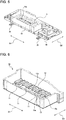
- Fig. 6 is a perspective view of the lower heat insulator included in the heat-pump hot-water supply outdoor unit according to the embodiment of the present disclosure when the lower heat insulator is viewed from the front right side.
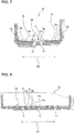
- Fig. 7 is a vertical cross-sectional view of the lower heat insulator included in the heat-pump hot-water supply outdoor unit according to the embodiment of the present disclosure, taken along the vertical plane parallel to the width direction of the lower heat insulator.
- Fig. 8 is a vertical cross-sectional view of the lower heat insulator included in the heat-pump hot-water supply outdoor unit according to the embodiment of the present disclosure, taken along the vertical plane parallel to the longitudinal direction of the lower heat insulator.
- the inner bottom portion 10a of the lower heat insulator 10 has an uneven shape with a protruding portion 12 and a recessed portion 13. More specifically, the inner bottom portion 10a of the lower heat insulator 10 includes a plurality of protruding portions 12 extending in a direction oriented in the width direction when the lower heat insulator 10 is viewed in plan. The protruding portions 12 are located apart from each other with a predetermined spacing. Between the protruding portions 12, a section lower than the protruding portions 12 is formed. This section is represented as the recessed portion 13. The recessed portion 13 is formed with at least one drain hole 11 extending through the inner bottom portion 10a. Note that in the present embodiment 1, a plurality of drain holes 11 are formed. The water-refrigerant heat exchanger 3 is placed on the protruding portions 12.
- the heat-pump hot-water supply outdoor unit 1 can significantly prevent the water-refrigerant heat exchanger 3 accommodated in a box-shaped heat insulator from being immersed in water even when condensation occurs on the water-refrigerant heat exchanger 3, compared to the conventional heat-pump hot-water supply outdoor unit. That is, the heat-pump hot-water supply outdoor unit 1 according to the present embodiment can significantly prevent the water-refrigerant heat exchanger 3 from corrosion, compared to the related-art heat-pump hot-water supply outdoor unit.
- the recessed portion 13 includes an inclined surface 13a that is inclined downward toward the drain hole 11.
- the inclined surface 13a included in the recessed portion 13 allows water to be collected in the recessed portion 13 to be more quickly discharged from the drain hole 11 to the outside of the lower heat insulator 10, compared to the case where the recessed portion 13 does not include the inclined surface 13a.
- the inclined surface 13a included in the recessed portion 13 can more significantly prevent the water-refrigerant heat exchanger 3 from being immersed in the water, compared to the above case. That is, the inclined surface 13a included in the recessed portion 13 can more significantly prevent the water-refrigerant heat exchanger 3 from corrosion, compared to the above case.
- the recessed portion 13 according to the present embodiment includes a plurality of inclined surfaces 13a, however, when the recessed portion 13 includes at least one inclined surface 13a, the effects described above can be obtained.
- each of the drain holes 11 is formed at a lower end portion 13c of the inclined surface 13a.
- each of the drain holes 11 is formed at a valley portion formed by the inclined surfaces 13a.
- the drain hole 11 formed at the lower end portion 13c of the inclined surface 13a allows water collecting in the recessed portion 13 to be further quickly discharged from the drain hole 11 to the outside of the lower heat insulator 10, and can further prevent the water-refrigerant heat exchanger 3 from corrosion. That is, the drain hole 11 formed at the lower end portion 13c of the inclined surface 13a can further prevent the water-refrigerant heat exchanger 3 from corrosion. Note that when at least one of the drain holes 11 is formed at the lower end portion 13c of the inclined surface 13a, the effects described above can be obtained.
- a part of the protruding portion 12 is positioned at an apex 13b of the inclined surface 13a. That is, a part of the protruding portion 12 is located at the highest point of the recessed portion 13.
- the protruding portion 12 located in this manner can minimize the protrusion height of the protruding portion 12 from the recessed portion 13, and can thus reduce material cost for the lower heat insulator 10.
- the recessed portion 13 In the recessed portion 13 according to the present embodiment and including the inclined surfaces 13a, at least some of the plurality of inclined surfaces 13a are inclined in the forward-rearward direction, while at least some of the plurality of inclined surfaces 13a are inclined in the rightward-leftward direction. Note that, in the present embodiment, all the inclined surfaces 13a are inclined in both the forward-rearward direction and the rightward-leftward direction.
- the heat-pump hot-water supply outdoor unit 1 may be installed while being inclined in the rightward-leftward direction.
- the heat-pump hot-water supply outdoor unit 1 may also be installed while being inclined in the forward-rearward direction.
- the heat-pump hot-water supply outdoor unit 1 may be installed while being inclined in both the rightward-leftward direction and the forward-rearward direction.
- the inclination direction of the inclined surfaces 13a is defined as described above, so that even when the heat-pump hot-water supply outdoor unit 1 is installed while being inclined in any direction, water collecting in the recessed portion 13 can still be discharged further quickly to the outside of the lower heat insulator 10.
- the inner bottom portion 10a of the lower heat insulator 10 includes the protruding portions 12, the inner bottom portion 10a may include any number of protruding portions 12.
- the protruding portion 12 is formed into an approximately frame-like shape in plan view, so that the water-refrigerant heat exchanger 3 can be placed on a single protruding portion 12.
- the protruding portions 12 are spaced apart from each other in a direction oriented in the longitudinal direction of the water-refrigerant heat exchanger 3 when the water-refrigerant heat exchanger 3 is viewed in plan. Positioning the protruding portions 12 in this manner can prevent distortion of the water-refrigerant heat exchanger 3. That is, this positioning can prevent the water-refrigerant heat exchanger 3 from being distorted and thus from being immersed in water collecting in the recessed portion 13.
- a corner portion 12a of the protruding portion 12 has an arc shape protruding outward on the protruding portion 12 in vertical cross-section.
- the corner portion 12a of the protruding portion 12 has the shape as described above, so that the contact area between the water-refrigerant heat exchanger 3 and the top surface of the protruding portion 12 can be decreased.
- the corner portion 12a of the protruding portion 12 has the shape as described above, so that water having flowed from the water-refrigerant heat exchanger 3 down to the top surface of the protruding portion 12 hardly stays on the top surface of the protruding portion 12.
- the corner portion 12a of the protruding portion 12 has the shape as described above, and this can thus reduce the period of time during which the water-refrigerant heat exchanger 3 contacts water, and accordingly can further prevent the water-refrigerant heat exchanger 3 from corrosion.
- the heat-pump hot-water supply outdoor unit 1 includes a box-shaped heat insulator, and the water-refrigerant heat exchanger 3 accommodated in the heat insulator and configured to heat water with refrigerant.
- the inner bottom portion 10a of the lower heat insulator 10 of the heat insulator has an uneven shape with the protruding portion 12 and the recessed portion 13.
- the recessed portion 13 is formed with the drain hole 11 extending through the inner bottom portion 10a.
- the water-refrigerant heat exchanger 3 is placed on the protruding portion 12 of the inner bottom portion 10a.
- the heat-pump hot-water supply outdoor unit 1 when condensation occurs on the surface of the water-refrigerant heat exchanger 3, and then water on the surface of the water-refrigerant heat exchanger 3 flows down to the inner bottom portion 10a of the lower heat insulator 10, the water is collected in the recessed portion 13 of the inner bottom portion 10a. Thereafter, the water collecting in the recessed portion 13 is discharged from the drain holes 11 formed on the recessed portion 13 to the outside of the lower heat insulator 10.
- the water-refrigerant heat exchanger 3 is raised by the protruding portions 12 relative to the recessed portion 13.
- the heat-pump hot-water supply outdoor unit 1 can significantly prevent the water-refrigerant heat exchanger 3 accommodated in a box-shaped heat insulator from being immersed in water even when condensation occurs on the water-refrigerant heat exchanger 3, compared to the conventional heat-pump hot-water supply outdoor unit. That is, the heat-pump hot-water supply outdoor unit 1 according to the present embodiment can significantly prevent the water-refrigerant heat exchanger 3 from corrosion, compared to the conventional heat-pump hot-water supply outdoor unit.
Landscapes
- Engineering & Computer Science (AREA)
- Chemical & Material Sciences (AREA)
- Combustion & Propulsion (AREA)
- Mechanical Engineering (AREA)
- General Engineering & Computer Science (AREA)
- Physics & Mathematics (AREA)
- Thermal Sciences (AREA)
- Heat-Pump Type And Storage Water Heaters (AREA)
- Housings, Intake/Discharge, And Installation Of Fluid Heaters (AREA)
Abstract
Description
- The present disclosure relates to a heat-pump hot-water supply outdoor unit having a water-refrigerant heat exchanger accommodated in a box-shaped heat insulator to reduce heat dissipation from the water-refrigerant heat exchanger to the outside.
- Energy-efficient heat-pump hot-water supply systems utilizing heat in the atmosphere are widely used. The heat-pump hot-water supply system includes a heat-pump hot-water supply outdoor unit. In the heat-pump hot-water supply outdoor unit, an evaporator configured to allow refrigerant to absorb heat in the atmosphere, a fan configured to deliver air to the evaporator, a compressor configured to compress the refrigerant, a water-refrigerant heat exchanger configured to heat water using the compressed high-temperature high-pressure refrigerant, and other devices are installed. The water-refrigerant heat exchanger is accommodated in a box-shaped heat insulator to reduce heat dissipation from the water-refrigerant heat exchanger to the outside during operation of the heat-pump hot-water supply outdoor unit. In a case where the water-refrigerant heat exchanger is accommodated in the box-shaped heat insulator, there is a possibility of corrosion of the water-refrigerant heat exchanger as described below. More specifically, when condensation occurs on the surface of the water-refrigerant heat exchanger, water on the surface of the water-refrigerant heat exchanger flows down and collects in an inner bottom portion of the heat insulator. When the water-refrigerant heat exchanger is immersed in the water collecting in the inner bottom portion of the heat insulator, there is a possibility of corrosion of the water-refrigerant heat exchanger. For this reason, it is desirable for the water-refrigerant heat exchanger not to be immersed in the water collecting in the inner bottom portion of the heat insulator. Note that the inner bottom portion of the heat insulator is a bottom portion of the heat insulator on the inner side thereof.
- Taking into the consideration the problem mentioned above, a related art heat-pump hot-water supply outdoor unit has been proposed, which is intended to prevent a water-refrigerant heat exchanger from being immersed in water collecting in an inner bottom portion of a heat insulator (see Patent Literature 1). Specifically, in the heat-pump hot-water supply outdoor unit disclosed in
Patent Literature 1, a heat insulator configured to accommodate therein a water-refrigerant heat exchanger is made up of a lower heat insulator and an upper heat insulator. The lower heat insulator has an open top, and has a box shape elongated in the rightward-leftward direction. The upper heat insulator covers the open top of the lower heat insulator. - The inner bottom portion of the lower heat insulator includes a flat portion. The water-refrigerant heat exchanger is placed on the flat portion. The inner bottom portion of the lower heat insulator is provided with a leaking-water discharge portion to prevent water from collecting in this inner bottom portion. This leaking-water discharge portion includes a through hole extending through the inner bottom portion of the lower heat insulator, and a filling sealing the through hole. According to
Patent Literature 1, with this configuration, water having flowed down to the inner bottom portion of the lower heat insulator flows through the through hole while passing through or melting the filling, and is discharged to the outside of the heat insulator. - Patent Literature 1: Japanese Unexamined Patent Application Publication No.
2015-45425 - In the heat-pump hot-water supply outdoor unit disclosed in
Patent Literature 1, the leaking-water discharge portion is provided in the flat portion of the inner bottom portion of the lower heat insulator. On the flat portion, the water-refrigerant heat exchanger is placed. Due to this structure, when condensation occurs on the surface of the water-refrigerant heat exchanger, and then water on the surface of the water-refrigerant heat exchanger flows down to the flat portion of the inner bottom portion of the lower heat insulator, the water-refrigerant heat exchanger is immersed in the water for a while until the water is discharged from the leaking-water discharge portion. In the inner bottom portion of the lower heat insulator, a location where the water-refrigerant heat exchanger is placed is the flat portion as described above. Thus, water having flowed down to the flat portion is more likely to collect in this flat portion. Accordingly, until a given amount of water is collected in the flat portion, the water being collected in the flat portion does not flow to the leaking-water discharge portion. Therefore, the heat-pump hot-water supply outdoor unit disclosed inPatent Literature 1 has a problem that the water-refrigerant heat exchanger cannot be sufficiently prevented from being immersed in water collecting in the inner bottom portion of the heat insulator, or cannot be sufficiently prevented from corrosion. - The present disclosure has been achieved to solve the above problems, and an object thereof is to provide a heat-pump hot-water supply outdoor unit that can significantly prevent a water-refrigerant heat exchanger accommodated in a box-shaped heat insulator from being immersed in water even when condensation occurs on the water-refrigerant heat exchanger, compared to the related-art heat-pump hot-water supply outdoor unit.
- A heat-pump hot-water supply outdoor unit according to an embodiment of the present disclosure includes: a box-shaped heat insulator; and a water-refrigerant heat exchanger accommodated in the heat insulator and configured to heat water with refrigerant, wherein an inner bottom portion of the heat insulator has an uneven shape with a protruding portion and a recessed portion, the recessed portion is formed with a drain hole extending through the inner bottom portion, and the water-refrigerant heat exchanger is placed on the protruding portion.
- In a heat-pump hot-water supply outdoor unit according to an embodiment of the present disclosure, when condensation occurs on the surface of a water-refrigerant heat exchanger, and then water on the surface of the water-refrigerant heat exchanger flows down to an inner bottom portion of a heat insulator, the water is collected in a recessed portion of the inner bottom portion. Thereafter, the water being collected in the recessed portion is discharged from a drain hole formed on the recessed portion to the outside of the heat insulator. With this configuration, the heat-pump hot-water supply outdoor unit according to the embodiment of the present disclosure can significantly prevent the water-refrigerant heat exchanger accommodated in a heat insulator with a box shape from being immersed in water even when condensation occurs on the water-refrigerant heat exchanger, compared to the related art heat-pump hot-water supply outdoor unit.
-
- [
Fig. 1] Fig. 1 is a piping system diagram illustrating a heat-pump hot-water supply system including a heat-pump hot-water supply outdoor unit according to an embodiment of the present disclosure. - [
Fig. 2] Fig. 2 is a perspective view of the heat-pump hot-water supply outdoor unit according to the embodiment of the present disclosure when the heat-pump hot-water supply outdoor unit is viewed from the front right side. - [
Fig. 3] Fig. 3 is an exploded perspective view of the heat-pump hot-water supply outdoor unit according to the embodiment of the present disclosure when the heat-pump hot-water supply outdoor unit is viewed from the front right side. - [
Fig. 4] Fig. 4 is a perspective view of a bottom plate, an upper heat insulator, a lower heat insulator, a water-refrigerant heat exchanger, and other devices included in the heat-pump hot-water supply outdoor unit according to the embodiment of the present disclosure when these elements are viewed from the front right side. - [
Fig. 5] Fig. 5 is a perspective view of the bottom plate, the lower heat insulator, the water-refrigerant heat exchanger, and other devices included in the heat-pump hot-water supply outdoor unit according to the embodiment of the present disclosure when these elements are viewed from the front right side. - [
Fig. 6] Fig. 6 is a perspective view of the lower heat insulator included in the heat-pump hot-water supply outdoor unit according to the embodiment of the present disclosure when the lower heat insulator is viewed from the front right side. - [
Fig. 7] Fig. 7 is a vertical cross-sectional view of the lower heat insulator included in the heat-pump hot-water supply outdoor unit according to the embodiment of the present disclosure, along the vertical plane parallel to the width direction of the lower heat insulator. - [
Fig. 8] Fig. 8 is a vertical cross-sectional view of the lower heat insulator included in the heat-pump hot-water supply outdoor unit according to the embodiment of the present disclosure, along the vertical plane parallel to the longitudinal direction of the lower heat insulator. - An example of a heat-pump hot-water supply outdoor unit according to an embodiment of the present disclosure will be described hereinafter with reference to the drawings. Note that the common components among the drawings are denoted by the same reference signs, and overlapping descriptions are thus simplified or omitted. The heat-pump hot-water supply outdoor unit according to the embodiment of the present disclosure may include all combinations of configurations that can be combined among the configurations described in the following embodiment.
-
Fig. 1 is a piping system diagram illustrating a heat-pump hot-water supply system including a heat-pump hot-water supply outdoor unit according to an embodiment of the present disclosure. As illustrated inFig. 1 , a heat-pump hot-water supply system 90 includes a heat-pump hot-water supplyoutdoor unit 1 and atank unit 91. The heat-pump hot-water supplyoutdoor unit 1 is located outdoors. Thetank unit 91 may be either located outdoors or located indoors. - The heat-pump hot-water supply
outdoor unit 1 includes acompressor 2, a water-refrigerant heat exchanger 3, afirst expansion valve 4a, asecond expansion valve 4b, anevaporator 5, aninternal heat exchanger 6, and afan 7. The heat-pump hot-water supplyoutdoor unit 1 includes a refrigerant circuit and performs operation in a refrigeration cycle, that is, in a heat-pump cycle. Thecompressor 2 compresses low-pressure refrigerant. For example, the refrigerant may be carbon dioxide. The water-refrigerant heat exchanger 3 includes arefrigerant pipe 3b and awater pipe 3a. High-temperature high-pressure refrigerant discharged from thecompressor 2 flows through therefrigerant pipe 3b. Water supplied from thetank unit 91 flows through thewater pipe 3a. The water-refrigerant heat exchanger 3 exchanges heat between high-temperature high-pressure refrigerant flowing through therefrigerant pipe 3b and water flowing through thewater pipe 3a. That is, water flowing through thewater pipe 3a is heated by high-temperature high-pressure refrigerant flowing through therefrigerant pipe 3b. - The
first expansion valve 4a and thesecond expansion valve 4b are examples of a pressure-reducing device configured to reduce the pressure of high-pressure refrigerant to obtain low-pressure refrigerant. The low-pressure refrigerant whose pressure has been reduced is brought into a two-phase gas-liquid state. Theevaporator 5 is a heat exchanger configured to exchange heat between the low-pressure refrigerant and the atmosphere. In theevaporator 5, the low-pressure refrigerant absorbs heat in the atmosphere and evaporates. Thefan 7 delivers air to theevaporator 5. This can help heat exchange in theevaporator 5. Theinternal heat exchanger 6 includes a high-pressure flow path and a low-pressure flow path. Theinternal heat exchanger 6 exchanges heat between high-pressure refrigerant flowing through the high-pressure flow path and low-pressure refrigerant flowing through the low-pressure flow path. The low-pressure refrigerant having evaporated in theevaporator 5 is absorbed into thecompressor 2 via the low-pressure flow path of theinternal heat exchanger 6. - The
tank unit 91 includes awater storage tank 92, apump 93, a flow-path switching valve 94, and abypass pipe 95. The heat-pump hot-water supplyoutdoor unit 1 and thetank unit 91 are connected to each other through anexternal pipe 96 and anexternal pipe 97. - In the
water storage tank 92, water to be heated and water having been heated is stored. In thewater storage tank 92, due to the difference in specific gravity of water caused by a temperature difference, thermal layering occurs where higher-temperature water is stored on top of lower-temperature water. To the top portion of thewater storage tank 92, a hot-water feed pipe (not illustrated) is connected to supply hot water to terminals including, for example, a hot-water tap, a shower, and a bath. To the bottom portion of thewater storage tank 92, a water feed pipe (not illustrated) is connected to supply water from the source such as the tap. When hot water is supplied from thewater storage tank 92, hot water in the top portion of thewater storage tank 92 is delivered to the hot-water feed pipe by a water pressure acting on the interior of thewater storage tank 92 from the water feed pipe. An equal amount of water to the amount of hot water having flowed out to the hot-water feed pipe, flows into thewater storage tank 92 from the water feed pipe, so that thewater storage tank 92 is kept filled with water. - The bottom portion of the
water storage tank 92 connects to an inlet of thepump 93 through a conduit. An outlet of thepump 93 connects to the flow-path switching valve 94. The flow-path switching valve 94 connects to thewater pipe 3a of the water-refrigerant heat exchanger 3 in the heat-pump hot-water supplyoutdoor unit 1 through theexternal pipe 96. - The heat-pump hot-
water supply system 90 can perform thermal storage operation to store water heated by the heat-pump hot-water supplyoutdoor unit 1 in thewater storage tank 92. The thermal storage operation is performed in the following manner. Thecompressor 2, thefan 7, and thepump 93 are operated. Water flowing out from the bottom portion of thewater storage tank 92 flows through thepump 93, the flow-path switching valve 94, and theexternal pipe 96, and flows into the water-refrigerant heat exchanger 3 in the heat-pump hot-water supplyoutdoor unit 1. This water is heated by refrigerant in the water-refrigerant heat exchanger 3 and becomes hot. The hot water heated in the water-refrigerant heat exchanger 3 reaches the temperature of approximately 65 to 90 degrees C, for example. The hot water having flowed out from the water-refrigerant heat exchanger 3 flows through theexternal pipe 97 to return to thetank unit 91, and then flows through atank top pipe 98 into the top portion of thewater storage tank 92. - The flow-
path switching valve 94 is capable of switching between flow paths such that water discharged from thepump 93 flows into thetank top pipe 98 through thebypass pipe 95, instead of flowing into the heat-pump hot-water supplyoutdoor unit 1. -
Fig. 2 is a perspective view of the heat-pump hot-water supply outdoor unit according to the embodiment of the present disclosure when the heat-pump hot-water supply outdoor unit is viewed from the front right side.Fig. 3 is an exploded perspective view of the heat-pump hot-water supply outdoor unit according to the embodiment of the present disclosure when the heat-pump hot-water supply outdoor unit is viewed from the front right side. As illustrated inFig. 2 , the heat-pump hot-water supplyoutdoor unit 1 includes a plurality ofleg portions 25. Theleg portions 25 are fixed to the ground or the floor. - As illustrated in
Fig. 3 , the heat-pump hot-water supplyoutdoor unit 1 includes abottom plate 18, afront panel 19, aside panel 20, and atop panel 21. Thebottom plate 18, thefront panel 19, theside panel 20, and thetop panel 21 form the outer casing of the heat-pump hot-water supplyoutdoor unit 1, that is, a housing of the heat-pump hot-water supplyoutdoor unit 1. It is preferable that thebottom plate 18, thefront panel 19, theside panel 20, and thetop panel 21 are made of metal. Thebottom plate 18 is equivalent to the base or frame of the heat-pump hot-water supplyoutdoor unit 1. Constituent devices including thecompressor 2 are installed on thebottom plate 18. Theleg portions 25 are fixed to the underside of thebottom plate 18. - The
front panel 19 covers the front side and the left side of the heat-pump hot-water supplyoutdoor unit 1. Theside panel 20 covers a part of the rear side and the right side of the heat-pump hot-water supplyoutdoor unit 1. Thetop panel 21 covers the top side of the heat-pump hot-water supplyoutdoor unit 1. Theevaporator 5 is located to cover the rear side and the left side of the heat-pump hot-water supplyoutdoor unit 1. - The interior of the outer casing of the heat-pump hot-water supply
outdoor unit 1 is divided into amachine chamber 14 and afan chamber 15 in which thefan 7 is located. Apartition plate 16 divides the interior of the outer casing of the heat-pump hot-water supplyoutdoor unit 1 into themachine chamber 14 and thefan chamber 15. In themachine chamber 14, thecompressor 2, the refrigerant pipe, and other devices are located. Thecompressor 2 is covered with acoustic insulation (not illustrated). In thefan chamber 15, thefan 7 is located between theevaporator 5 and thefront panel 19. Thefan 7 according to the present embodiment includes a propeller fan. In thefan chamber 15, a case 8 is located below thefan 7. The water-refrigerant heat exchanger 3 is accommodated in the case 8 in a state of being covered with an upper heat insulator 9 and alower heat insulator 10 which are described later. - The
front panel 19 is formed with an opening at a position where the opening faces thefan 7. Agrille 24 configured to cover this opening is attached to thefront panel 19. When thefan 7 is operated, the outside air, that is, the atmosphere passes through theevaporator 5 and flows into thefan chamber 15, and is discharged from thegrille 24 to the outside of the heat-pump hot-water supplyoutdoor unit 1. - The heat-pump hot-water supply
outdoor unit 1 includes an electrical-component storage box 17. The electrical-component storage box 17 is located in the space, occupying a part of the upper portion of thefan chamber 15 and the upper portion of themachine chamber 14. In the electrical-component storage box 17, electrical components are accommodated, including, for example, an inverter power supply to control driving of a motor of thecompressor 2 and a motor of thefan 7. There is a terminal block near the electrical-component storage box 17. The terminal block is used to connect external electric wires to the electrical components in the electrical-component storage box 17. Theservice panel 22 is removably attached to theside panel 20. Theservice panel 22 protects the terminal block. Below theservice panel 22, a connection-portion cover 23 is removably attached to theside panel 20. The connection-portion cover 23 protects a connection portion (not illustrated) to which theexternal pipe 96 and theexternal pipe 97 are connected. -
Fig. 4 is a perspective view of a bottom plate, an upper heat insulator, a lower heat insulator, a water-refrigerant heat exchanger, and other devices included in the heat-pump hot-water supply outdoor unit according to the embodiment of the present disclosure when these components are viewed from the front right side. As illustrated inFig. 4 , thebottom plate 18 has, for example, a shape formed with a plurality of irregularities, steps, and inclined surfaces with a height difference of approximately 1 centimeter. Thebottom plate 18 may be formed by pressing which is, for example, drawing. Thebottom plate 18 has impermeable properties. - The
bottom plate 18 is formed with a drain port (not illustrated). It is desirable for this drain port to be located at the lowest position in thebottom plate 18. Since during operation of the heat-pump hot-water supplyoutdoor unit 1, the temperature of theevaporator 5 is relatively low, water contained in the air passing through theevaporator 5 may condense on the surface of theevaporator 5. The condensed water falls by gravity. Thebottom plate 18 receives the water. The water flows toward the position of the drain port due to the height difference formed on thebottom plate 18, and is discharged downward from thebottom plate 18 through the drain port. - A hopper or the like configured to receive water discharged from the drain port may be provided at the installation location of the heat-pump hot-water supply
outdoor unit 1. Thebottom plate 18 is formed with the drain port, and thus the following effects can be obtained. Condensed water and the like generated on the surface of theevaporator 5 is collected by thebottom plate 18, and then discharged from the drain port to the outside of the heat-pump hot-water supplyoutdoor unit 1. This can avoid water from leaking from a section other than the drain port. This can ensure that a user avoids misunderstanding that water leaks from the heat-pump hot-water supplyoutdoor unit 1. - The water-
refrigerant heat exchanger 3 is accommodated in a box-shaped heat insulator, and can thus reduce heat dissipation to the outside during operation of the heat-pump hot-water supplyoutdoor unit 1. The box-shaped heat insulator according to the present embodiment is divided into two, an upper part and a lower part. The heat insulator is made up of thelower heat insulator 10 and the upper heat insulator 9. Thelower heat insulator 10 has a box shape to accommodate therein the water-refrigerant heat exchanger 3. The upper heat insulator 9 has a lid-like shape to cover the topside of thelower heat insulator 10. -
Fig. 5 is a perspective view of the bottom plate, the lower heat insulator, the water-refrigerant heat exchanger, and other devices included in the heat-pump hot-water supply outdoor unit according to the embodiment of the present disclosure when these elements are viewed from the front right side. Note that a D1 direction illustrated by the arrow inFig. 5 represents the rightward-leftward direction of the heat-pump hot-water supplyoutdoor unit 1. That is, the D1 direction represents the rightward-leftward direction of thelower heat insulator 10 and the water-refrigerant heat exchanger 3. A D2 direction illustrated by the arrow inFig. 5 represents the forward-rearward direction of the heat-pump hot-water supplyoutdoor unit 1. That is, the D2 direction represents the forward-rearward direction of thelower heat insulator 10 and the water-refrigerant heat exchanger 3. - The interior space of the
lower heat insulator 10 has an approximately cuboid shape elongated in the rightward-leftward direction. The water-refrigerant heat exchanger 3 is placed on aninner bottom portion 10a of thelower heat insulator 10. Note that theinner bottom portion 10a of thelower heat insulator 10 is a bottom portion of thelower heat insulator 10 on the inner side thereof. The water-refrigerant heat exchanger 3 is a pipe-like heat exchanger such as a double-pipe heat exchanger. The water-refrigerant heat exchanger 3 has such a structure that the water-refrigerant heat exchanger 3 is layered in the upward-downward direction while being bent into a rectangular shape corresponding to the shape of the interior space of thelower heat insulator 10. That is, when the water-refrigerant heat exchanger 3 is viewed in plan, the rightward-leftward direction thereof is the longitudinal direction, and the forward-rearward direction thereof is the width direction. -
Fig. 6 is a perspective view of the lower heat insulator included in the heat-pump hot-water supply outdoor unit according to the embodiment of the present disclosure when the lower heat insulator is viewed from the front right side.Fig. 7 is a vertical cross-sectional view of the lower heat insulator included in the heat-pump hot-water supply outdoor unit according to the embodiment of the present disclosure, taken along the vertical plane parallel to the width direction of the lower heat insulator.Fig. 8 is a vertical cross-sectional view of the lower heat insulator included in the heat-pump hot-water supply outdoor unit according to the embodiment of the present disclosure, taken along the vertical plane parallel to the longitudinal direction of the lower heat insulator. - The
inner bottom portion 10a of thelower heat insulator 10 has an uneven shape with a protrudingportion 12 and a recessedportion 13. More specifically, theinner bottom portion 10a of thelower heat insulator 10 includes a plurality of protrudingportions 12 extending in a direction oriented in the width direction when thelower heat insulator 10 is viewed in plan. The protrudingportions 12 are located apart from each other with a predetermined spacing. Between the protrudingportions 12, a section lower than the protrudingportions 12 is formed. This section is represented as the recessedportion 13. The recessedportion 13 is formed with at least onedrain hole 11 extending through theinner bottom portion 10a. Note that in thepresent embodiment 1, a plurality of drain holes 11 are formed. The water-refrigerant heat exchanger 3 is placed on the protrudingportions 12. - Due to this configuration, in the heat-pump hot-water supply
outdoor unit 1 according to the present embodiment, when condensation occurs on the surface of the water-refrigerant heat exchanger 3, and then water on the surface of the water-refrigerant heat exchanger 3 flows down to theinner bottom portion 10a of thelower heat insulator 10, the water collects in the recessedportion 13 of theinner bottom portion 10a. Thereafter, the water collecting in the recessedportion 13 is discharged from the drain holes 11 formed on the recessedportion 13 to the outside of thelower heat insulator 10. The water-refrigerant heat exchanger 3 is raised by the protrudingportions 12 relative to the recessedportion 13. Due to this configuration, the heat-pump hot-water supplyoutdoor unit 1 according to the present embodiment can significantly prevent the water-refrigerant heat exchanger 3 accommodated in a box-shaped heat insulator from being immersed in water even when condensation occurs on the water-refrigerant heat exchanger 3, compared to the conventional heat-pump hot-water supply outdoor unit. That is, the heat-pump hot-water supplyoutdoor unit 1 according to the present embodiment can significantly prevent the water-refrigerant heat exchanger 3 from corrosion, compared to the related-art heat-pump hot-water supply outdoor unit. - Note that water discharged from the drain holes 11 to the outside of the
lower heat insulator 10 flows down to thebottom plate 18. The water having flowed down to thebottom plate 18 flows toward the position of the drain port due to the height difference formed on thebottom plate 18, and is discharged downward from thebottom plate 18 through the drain port. - In the present embodiment, the recessed
portion 13 includes aninclined surface 13a that is inclined downward toward thedrain hole 11. Theinclined surface 13a included in the recessedportion 13 allows water to be collected in the recessedportion 13 to be more quickly discharged from thedrain hole 11 to the outside of thelower heat insulator 10, compared to the case where the recessedportion 13 does not include theinclined surface 13a. With this configuration, theinclined surface 13a included in the recessedportion 13 can more significantly prevent the water-refrigerant heat exchanger 3 from being immersed in the water, compared to the above case. That is, theinclined surface 13a included in the recessedportion 13 can more significantly prevent the water-refrigerant heat exchanger 3 from corrosion, compared to the above case. Note that the recessedportion 13 according to the present embodiment includes a plurality ofinclined surfaces 13a, however, when the recessedportion 13 includes at least oneinclined surface 13a, the effects described above can be obtained. - In the present embodiment, each of the drain holes 11 is formed at a
lower end portion 13c of theinclined surface 13a. In other words, in the recessedportion 13 according to the present embodiment and including theinclined surfaces 13a, each of the drain holes 11 is formed at a valley portion formed by theinclined surfaces 13a. Thedrain hole 11 formed at thelower end portion 13c of theinclined surface 13a allows water collecting in the recessedportion 13 to be further quickly discharged from thedrain hole 11 to the outside of thelower heat insulator 10, and can further prevent the water-refrigerant heat exchanger 3 from corrosion. That is, thedrain hole 11 formed at thelower end portion 13c of theinclined surface 13a can further prevent the water-refrigerant heat exchanger 3 from corrosion. Note that when at least one of the drain holes 11 is formed at thelower end portion 13c of theinclined surface 13a, the effects described above can be obtained. - In the present embodiment, when the
lower heat insulator 10 is viewed in plan, a part of the protrudingportion 12 is positioned at an apex 13b of theinclined surface 13a. That is, a part of the protrudingportion 12 is located at the highest point of the recessedportion 13. The protrudingportion 12 located in this manner can minimize the protrusion height of the protrudingportion 12 from the recessedportion 13, and can thus reduce material cost for thelower heat insulator 10. - In the recessed
portion 13 according to the present embodiment and including theinclined surfaces 13a, at least some of the plurality ofinclined surfaces 13a are inclined in the forward-rearward direction, while at least some of the plurality ofinclined surfaces 13a are inclined in the rightward-leftward direction. Note that, in the present embodiment, all theinclined surfaces 13a are inclined in both the forward-rearward direction and the rightward-leftward direction. The heat-pump hot-water supplyoutdoor unit 1 may be installed while being inclined in the rightward-leftward direction. The heat-pump hot-water supplyoutdoor unit 1 may also be installed while being inclined in the forward-rearward direction. Furthermore, the heat-pump hot-water supplyoutdoor unit 1 may be installed while being inclined in both the rightward-leftward direction and the forward-rearward direction. In a case where the recessedportion 13 includes theinclined surfaces 13a, the inclination direction of theinclined surfaces 13a is defined as described above, so that even when the heat-pump hot-water supplyoutdoor unit 1 is installed while being inclined in any direction, water collecting in the recessedportion 13 can still be discharged further quickly to the outside of thelower heat insulator 10. - Note that, while the
inner bottom portion 10a of thelower heat insulator 10 according to the present embodiment includes the protrudingportions 12, theinner bottom portion 10a may include any number of protrudingportions 12. For example, the protrudingportion 12 is formed into an approximately frame-like shape in plan view, so that the water-refrigerant heat exchanger 3 can be placed on a single protrudingportion 12. In a case where theinner bottom portion 10a includes the protrudingportions 12, it is preferable to position each of the protrudingportions 12 in the manner as illustrated inFigs. 6 and8 . More specifically, it is preferable that the protrudingportions 12 are spaced apart from each other in a direction oriented in the longitudinal direction of the water-refrigerant heat exchanger 3 when the water-refrigerant heat exchanger 3 is viewed in plan. Positioning the protrudingportions 12 in this manner can prevent distortion of the water-refrigerant heat exchanger 3. That is, this positioning can prevent the water-refrigerant heat exchanger 3 from being distorted and thus from being immersed in water collecting in the recessedportion 13. - In the present embodiment, a
corner portion 12a of the protrudingportion 12 has an arc shape protruding outward on the protrudingportion 12 in vertical cross-section. Thecorner portion 12a of the protrudingportion 12 has the shape as described above, so that the contact area between the water-refrigerant heat exchanger 3 and the top surface of the protrudingportion 12 can be decreased. Thecorner portion 12a of the protrudingportion 12 has the shape as described above, so that water having flowed from the water-refrigerant heat exchanger 3 down to the top surface of the protrudingportion 12 hardly stays on the top surface of the protrudingportion 12. For this reason, thecorner portion 12a of the protrudingportion 12 has the shape as described above, and this can thus reduce the period of time during which the water-refrigerant heat exchanger 3 contacts water, and accordingly can further prevent the water-refrigerant heat exchanger 3 from corrosion. - The heat-pump hot-water supply
outdoor unit 1 according to the present embodiment includes a box-shaped heat insulator, and the water-refrigerant heat exchanger 3 accommodated in the heat insulator and configured to heat water with refrigerant. Theinner bottom portion 10a of thelower heat insulator 10 of the heat insulator has an uneven shape with the protrudingportion 12 and the recessedportion 13. The recessedportion 13 is formed with thedrain hole 11 extending through theinner bottom portion 10a. The water-refrigerant heat exchanger 3 is placed on the protrudingportion 12 of theinner bottom portion 10a. - In the heat-pump hot-water supply
outdoor unit 1 according to the present embodiment, when condensation occurs on the surface of the water-refrigerant heat exchanger 3, and then water on the surface of the water-refrigerant heat exchanger 3 flows down to theinner bottom portion 10a of thelower heat insulator 10, the water is collected in the recessedportion 13 of theinner bottom portion 10a. Thereafter, the water collecting in the recessedportion 13 is discharged from the drain holes 11 formed on the recessedportion 13 to the outside of thelower heat insulator 10. The water-refrigerant heat exchanger 3 is raised by the protrudingportions 12 relative to the recessedportion 13. Due to this configuration, the heat-pump hot-water supplyoutdoor unit 1 according to the present embodiment can significantly prevent the water-refrigerant heat exchanger 3 accommodated in a box-shaped heat insulator from being immersed in water even when condensation occurs on the water-refrigerant heat exchanger 3, compared to the conventional heat-pump hot-water supply outdoor unit. That is, the heat-pump hot-water supplyoutdoor unit 1 according to the present embodiment can significantly prevent the water-refrigerant heat exchanger 3 from corrosion, compared to the conventional heat-pump hot-water supply outdoor unit. -
- 1
- heat-pump hot-water supply outdoor unit
- 2
- compressor
- 3
- water-refrigerant heat exchanger
- 3a
- water pipe
- 3b
- refrigerant pipe
- 4a
- first expansion valve
- 4b
- second expansion valve
- 5
- evaporator
- 6
- internal heat exchanger
- 7
- fan
- 8
- case
- 9
- upper heat insulator
- 10
- lower heat insulator
- 10a
- inner bottom portion
- 11
- drain hole
- 12
- protruding portion
- 12
- a corner portion
- 13
- recessed portion
- 13a
- inclined surface
- 13b
- apex
- 13c
- lower end portion
- 14
- machine chamber
- 15
- fan chamber
- 16
- partition plate
- 17
- electrical-component storage box
- 18
- bottom plate
- 19
- front panel
- 20
- side panel
- 21
- top panel
- 22
- service panel
- 23
- connection-portion cover
- 24
- grille
- 25
- leg portion
- 90
- heat-pump hot-water supply system
- 91
- tank unit
- 92
- water storage tank
- 93
- pump
- 94
- flow-path switching valve
- 95
- bypass pipe
- 96
- external pipe
- 97
- external pipe
- 98
- tank top pipe
Claims (7)
- A heat-pump hot-water supply outdoor unit comprising:a box-shaped heat insulator; anda water-refrigerant heat exchanger accommodated in the heat insulator and configured to heat water with refrigerant, whereinan inner bottom portion of the heat insulator has an uneven shape with a protruding portion and a recessed portion,the recessed portion is formed with a drain hole extending through the inner bottom portion, andthe water-refrigerant heat exchanger is placed on the protruding portion.
- The heat-pump hot-water supply outdoor unit of claim 1, wherein the recessed portion includes an inclined surface that is inclined downward toward the drain hole.
- The heat-pump hot-water supply outdoor unit of claim 2, wherein when the heat insulator is viewed in plan, a part of the protruding portion is positioned at an apex of the inclined surface.
- The heat-pump hot-water supply outdoor unit of claim 2 or 3, wherein the drain hole is formed at a lower end portion of the inclined surface.
- The heat-pump hot-water supply outdoor unit of any one of claims 2 to 4, wherein
the recessed portion includes a plurality of the inclined surfaces,
at least some of a plurality of the inclined surfaces are inclined in a forward-rearward direction, and
at least some of a plurality of the inclined surfaces are inclined in a rightward-leftward direction. - The heat-pump hot-water supply outdoor unit of any one of claims 1 to 5, wherein
the inner bottom portion includes a plurality of the protruding portions, and
a plurality of the protruding portions are spaced apart from each other in a direction oriented in a longitudinal direction of the water-refrigerant heat exchanger when the water-refrigerant heat exchanger is viewed in plan. - The heat-pump hot-water supply outdoor unit of any one of claims 1 to 6, wherein a corner portion of the protruding portion has an arc shape protruding outward on the protruding portion in vertical cross-section.
Applications Claiming Priority (1)
| Application Number | Priority Date | Filing Date | Title |
|---|---|---|---|
| PCT/JP2018/027274 WO2020017021A1 (en) | 2018-07-20 | 2018-07-20 | Heat pump water heater outdoor unit |
Publications (3)
| Publication Number | Publication Date |
|---|---|
| EP3825622A1 true EP3825622A1 (en) | 2021-05-26 |
| EP3825622A4 EP3825622A4 (en) | 2021-11-17 |
| EP3825622B1 EP3825622B1 (en) | 2024-11-06 |
Family
ID=69163676
Family Applications (1)
| Application Number | Title | Priority Date | Filing Date |
|---|---|---|---|
| EP18926577.0A Active EP3825622B1 (en) | 2018-07-20 | 2018-07-20 | Heat-pump hot-water supply outdoor unit |
Country Status (4)
| Country | Link |
|---|---|
| EP (1) | EP3825622B1 (en) |
| JP (1) | JP6921326B2 (en) |
| NZ (1) | NZ770289A (en) |
| WO (1) | WO2020017021A1 (en) |
Cited By (3)
| Publication number | Priority date | Publication date | Assignee | Title |
|---|---|---|---|---|
| EP4425057A1 (en) * | 2023-03-03 | 2024-09-04 | Daikin Europe N.V. | Heat source unit of a heat pump |
| EP4372292A4 (en) * | 2021-07-16 | 2024-10-30 | Hefei Midea Heating & Ventilating Equipment Co., Ltd. | AIR CONDITIONER |
| EP4495493A4 (en) * | 2022-03-18 | 2026-03-18 | Fujitsu General Ltd | OUTDOOR UNIT OF A HEAT PUMP CIRCUIT DEVICE AND HEAT PUMP CIRCUIT DEVICE |
Families Citing this family (2)
| Publication number | Priority date | Publication date | Assignee | Title |
|---|---|---|---|---|
| DE102020112799A1 (en) * | 2020-05-12 | 2021-11-18 | Viessmann Werke Gmbh & Co Kg | Heat pump system |
| CN113686050B (en) * | 2021-08-23 | 2024-12-27 | 银川华誉智慧能源科技有限公司 | A modular heat pump unit and system |
Family Cites Families (9)
| Publication number | Priority date | Publication date | Assignee | Title |
|---|---|---|---|---|
| JP3931878B2 (en) * | 2003-11-19 | 2007-06-20 | 松下電器産業株式会社 | Heat pump type heat source device |
| JP2010169273A (en) * | 2009-01-20 | 2010-08-05 | Corona Corp | Heat pump type hot water heating device |
| JP2011133149A (en) * | 2009-12-24 | 2011-07-07 | Panasonic Corp | Heat pump type heat source device and heat pump water heater using the same |
| JP5527113B2 (en) * | 2010-08-31 | 2014-06-18 | パナソニック株式会社 | Heat pump heat source machine |
| JP6028221B2 (en) * | 2012-07-12 | 2016-11-16 | パナソニックIpマネジメント株式会社 | Heat exchanger unit and heat pump hot water heater equipped with the same |
| JP5754423B2 (en) * | 2012-08-01 | 2015-07-29 | 三菱電機株式会社 | Heat pump water heater outdoor unit |
| JP6249271B2 (en) * | 2013-08-27 | 2017-12-20 | 株式会社ノーリツ | Heat pump water heater |
| JP6231425B2 (en) * | 2014-04-21 | 2017-11-15 | 株式会社コロナ | Refrigerant water heat exchanger |
| JP6416700B2 (en) * | 2015-06-03 | 2018-10-31 | 株式会社コロナ | Heat pump water heater |
-
2018
- 2018-07-20 JP JP2020530839A patent/JP6921326B2/en not_active Expired - Fee Related
- 2018-07-20 NZ NZ770289A patent/NZ770289A/en not_active IP Right Cessation
- 2018-07-20 WO PCT/JP2018/027274 patent/WO2020017021A1/en not_active Ceased
- 2018-07-20 EP EP18926577.0A patent/EP3825622B1/en active Active
Cited By (4)
| Publication number | Priority date | Publication date | Assignee | Title |
|---|---|---|---|---|
| EP4372292A4 (en) * | 2021-07-16 | 2024-10-30 | Hefei Midea Heating & Ventilating Equipment Co., Ltd. | AIR CONDITIONER |
| EP4495493A4 (en) * | 2022-03-18 | 2026-03-18 | Fujitsu General Ltd | OUTDOOR UNIT OF A HEAT PUMP CIRCUIT DEVICE AND HEAT PUMP CIRCUIT DEVICE |
| EP4425057A1 (en) * | 2023-03-03 | 2024-09-04 | Daikin Europe N.V. | Heat source unit of a heat pump |
| WO2024184247A1 (en) * | 2023-03-03 | 2024-09-12 | Daikin Europe N.V. | Heat source unit of a heat pump |
Also Published As
| Publication number | Publication date |
|---|---|
| WO2020017021A1 (en) | 2020-01-23 |
| NZ770289A (en) | 2022-11-25 |
| EP3825622B1 (en) | 2024-11-06 |
| EP3825622A4 (en) | 2021-11-17 |
| JPWO2020017021A1 (en) | 2021-04-30 |
| JP6921326B2 (en) | 2021-08-18 |
Similar Documents
| Publication | Publication Date | Title |
|---|---|---|
| EP3825622B1 (en) | Heat-pump hot-water supply outdoor unit | |
| JP6028815B2 (en) | Heat exchange unit of air conditioner | |
| JP4700690B2 (en) | Heat pump type water heater | |
| JP6976407B2 (en) | Air conditioner | |
| CN101111719B (en) | Outdoor unit of air conditioning unit | |
| KR101492384B1 (en) | Outdoor unit for refrigeration device | |
| EP3276279B1 (en) | Heat pump hot-water-supply outdoor device, and hot-water-supply device | |
| EP3012551A1 (en) | Heat pump apparatus | |
| JP5280236B2 (en) | Air conditioner outdoor unit | |
| KR20190006546A (en) | Refrigeration cycle unit | |
| CN110785613B (en) | Outdoor unit of refrigerator | |
| CN103822358B (en) | Hot water storing tank unit | |
| US20240003555A1 (en) | Electric component unit, and outdoor unit of refrigeration apparatus | |
| JPWO2018062054A1 (en) | Refrigeration cycle device | |
| JP7433768B2 (en) | Outdoor unit of refrigeration cycle equipment | |
| JP2024051511A (en) | Heat pump cycle equipment | |
| CN112432257B (en) | Refrigerant cuts device and air conditioning system | |
| JP2011142131A (en) | Refrigerator | |
| JP2010002121A (en) | Refrigerating device | |
| EP3124890B1 (en) | Heat-generating unit | |
| CN217876185U (en) | Outdoor machine of air conditioner | |
| CN111526699A (en) | Electrical equipment, electrical box and temperature control method thereof | |
| JP2006214633A (en) | Air conditioner outdoor unit | |
| JP6650846B2 (en) | Outdoor unit | |
| JP2008145039A (en) | Insulated piping structure of air conditioner |
Legal Events
| Date | Code | Title | Description |
|---|---|---|---|
| STAA | Information on the status of an ep patent application or granted ep patent |
Free format text: STATUS: THE INTERNATIONAL PUBLICATION HAS BEEN MADE |
|
| PUAI | Public reference made under article 153(3) epc to a published international application that has entered the european phase |
Free format text: ORIGINAL CODE: 0009012 |
|
| STAA | Information on the status of an ep patent application or granted ep patent |
Free format text: STATUS: REQUEST FOR EXAMINATION WAS MADE |
|
| 17P | Request for examination filed |
Effective date: 20201216 |
|
| AK | Designated contracting states |
Kind code of ref document: A1 Designated state(s): AL AT BE BG CH CY CZ DE DK EE ES FI FR GB GR HR HU IE IS IT LI LT LU LV MC MK MT NL NO PL PT RO RS SE SI SK SM TR |
|
| A4 | Supplementary search report drawn up and despatched |
Effective date: 20210629 |
|
| RIC1 | Information provided on ipc code assigned before grant |
Ipc: F24H 9/02 20060101AFI20210623BHEP Ipc: F24D 17/02 20060101ALI20210623BHEP Ipc: F24D 19/00 20060101ALI20210623BHEP Ipc: F24D 19/08 20060101ALI20210623BHEP Ipc: F24F 1/16 20110101ALI20210623BHEP Ipc: F24F 1/36 20110101ALI20210623BHEP Ipc: F24F 1/56 20110101ALI20210623BHEP Ipc: F24H 4/02 20060101ALI20210623BHEP |
|
| DAV | Request for validation of the european patent (deleted) | ||
| DAX | Request for extension of the european patent (deleted) | ||
| RA4 | Supplementary search report drawn up and despatched (corrected) |
Effective date: 20211020 |
|
| RIC1 | Information provided on ipc code assigned before grant |
Ipc: F24H 4/02 20060101ALI20211012BHEP Ipc: F24F 1/56 20110101ALI20211012BHEP Ipc: F24F 1/36 20110101ALI20211012BHEP Ipc: F24F 1/16 20110101ALI20211012BHEP Ipc: F24D 19/08 20060101ALI20211012BHEP Ipc: F24D 19/00 20060101ALI20211012BHEP Ipc: F24D 17/02 20060101ALI20211012BHEP Ipc: F24H 9/02 20060101AFI20211012BHEP |
|
| GRAP | Despatch of communication of intention to grant a patent |
Free format text: ORIGINAL CODE: EPIDOSNIGR1 |
|
| STAA | Information on the status of an ep patent application or granted ep patent |
Free format text: STATUS: GRANT OF PATENT IS INTENDED |
|
| INTG | Intention to grant announced |
Effective date: 20240725 |
|
| GRAS | Grant fee paid |
Free format text: ORIGINAL CODE: EPIDOSNIGR3 |
|
| GRAA | (expected) grant |
Free format text: ORIGINAL CODE: 0009210 |
|
| STAA | Information on the status of an ep patent application or granted ep patent |
Free format text: STATUS: THE PATENT HAS BEEN GRANTED |
|
| AK | Designated contracting states |
Kind code of ref document: B1 Designated state(s): AL AT BE BG CH CY CZ DE DK EE ES FI FR GB GR HR HU IE IS IT LI LT LU LV MC MK MT NL NO PL PT RO RS SE SI SK SM TR |
|
| REG | Reference to a national code |
Ref country code: GB Ref legal event code: FG4D |
|
| REG | Reference to a national code |
Ref country code: CH Ref legal event code: EP |
|
| REG | Reference to a national code |
Ref country code: DE Ref legal event code: R096 Ref document number: 602018076434 Country of ref document: DE |
|
| REG | Reference to a national code |
Ref country code: IE Ref legal event code: FG4D |
|
| REG | Reference to a national code |
Ref country code: LT Ref legal event code: MG9D |
|
| REG | Reference to a national code |
Ref country code: NL Ref legal event code: MP Effective date: 20241106 |
|
| PG25 | Lapsed in a contracting state [announced via postgrant information from national office to epo] |
Ref country code: HR Free format text: LAPSE BECAUSE OF FAILURE TO SUBMIT A TRANSLATION OF THE DESCRIPTION OR TO PAY THE FEE WITHIN THE PRESCRIBED TIME-LIMIT Effective date: 20241106 Ref country code: PT Free format text: LAPSE BECAUSE OF FAILURE TO SUBMIT A TRANSLATION OF THE DESCRIPTION OR TO PAY THE FEE WITHIN THE PRESCRIBED TIME-LIMIT Effective date: 20250306 Ref country code: IS Free format text: LAPSE BECAUSE OF FAILURE TO SUBMIT A TRANSLATION OF THE DESCRIPTION OR TO PAY THE FEE WITHIN THE PRESCRIBED TIME-LIMIT Effective date: 20250306 |
|
| PG25 | Lapsed in a contracting state [announced via postgrant information from national office to epo] |
Ref country code: FI Free format text: LAPSE BECAUSE OF FAILURE TO SUBMIT A TRANSLATION OF THE DESCRIPTION OR TO PAY THE FEE WITHIN THE PRESCRIBED TIME-LIMIT Effective date: 20241106 Ref country code: NL Free format text: LAPSE BECAUSE OF FAILURE TO SUBMIT A TRANSLATION OF THE DESCRIPTION OR TO PAY THE FEE WITHIN THE PRESCRIBED TIME-LIMIT Effective date: 20241106 |
|
| REG | Reference to a national code |
Ref country code: AT Ref legal event code: MK05 Ref document number: 1739722 Country of ref document: AT Kind code of ref document: T Effective date: 20241106 |
|
| PG25 | Lapsed in a contracting state [announced via postgrant information from national office to epo] |
Ref country code: BG Free format text: LAPSE BECAUSE OF FAILURE TO SUBMIT A TRANSLATION OF THE DESCRIPTION OR TO PAY THE FEE WITHIN THE PRESCRIBED TIME-LIMIT Effective date: 20241106 |
|
| PG25 | Lapsed in a contracting state [announced via postgrant information from national office to epo] |
Ref country code: ES Free format text: LAPSE BECAUSE OF FAILURE TO SUBMIT A TRANSLATION OF THE DESCRIPTION OR TO PAY THE FEE WITHIN THE PRESCRIBED TIME-LIMIT Effective date: 20241106 |
|
| PG25 | Lapsed in a contracting state [announced via postgrant information from national office to epo] |
Ref country code: NO Free format text: LAPSE BECAUSE OF FAILURE TO SUBMIT A TRANSLATION OF THE DESCRIPTION OR TO PAY THE FEE WITHIN THE PRESCRIBED TIME-LIMIT Effective date: 20250206 |
|
| PG25 | Lapsed in a contracting state [announced via postgrant information from national office to epo] |
Ref country code: LV Free format text: LAPSE BECAUSE OF FAILURE TO SUBMIT A TRANSLATION OF THE DESCRIPTION OR TO PAY THE FEE WITHIN THE PRESCRIBED TIME-LIMIT Effective date: 20241106 Ref country code: GR Free format text: LAPSE BECAUSE OF FAILURE TO SUBMIT A TRANSLATION OF THE DESCRIPTION OR TO PAY THE FEE WITHIN THE PRESCRIBED TIME-LIMIT Effective date: 20250207 Ref country code: AT Free format text: LAPSE BECAUSE OF FAILURE TO SUBMIT A TRANSLATION OF THE DESCRIPTION OR TO PAY THE FEE WITHIN THE PRESCRIBED TIME-LIMIT Effective date: 20241106 |
|
| PG25 | Lapsed in a contracting state [announced via postgrant information from national office to epo] |
Ref country code: PL Free format text: LAPSE BECAUSE OF FAILURE TO SUBMIT A TRANSLATION OF THE DESCRIPTION OR TO PAY THE FEE WITHIN THE PRESCRIBED TIME-LIMIT Effective date: 20241106 |
|
| PG25 | Lapsed in a contracting state [announced via postgrant information from national office to epo] |
Ref country code: RS Free format text: LAPSE BECAUSE OF FAILURE TO SUBMIT A TRANSLATION OF THE DESCRIPTION OR TO PAY THE FEE WITHIN THE PRESCRIBED TIME-LIMIT Effective date: 20250206 |
|
| PG25 | Lapsed in a contracting state [announced via postgrant information from national office to epo] |
Ref country code: SM Free format text: LAPSE BECAUSE OF FAILURE TO SUBMIT A TRANSLATION OF THE DESCRIPTION OR TO PAY THE FEE WITHIN THE PRESCRIBED TIME-LIMIT Effective date: 20241106 |
|
| PG25 | Lapsed in a contracting state [announced via postgrant information from national office to epo] |
Ref country code: DK Free format text: LAPSE BECAUSE OF FAILURE TO SUBMIT A TRANSLATION OF THE DESCRIPTION OR TO PAY THE FEE WITHIN THE PRESCRIBED TIME-LIMIT Effective date: 20241106 |
|
| PG25 | Lapsed in a contracting state [announced via postgrant information from national office to epo] |
Ref country code: EE Free format text: LAPSE BECAUSE OF FAILURE TO SUBMIT A TRANSLATION OF THE DESCRIPTION OR TO PAY THE FEE WITHIN THE PRESCRIBED TIME-LIMIT Effective date: 20241106 |
|
| PG25 | Lapsed in a contracting state [announced via postgrant information from national office to epo] |
Ref country code: RO Free format text: LAPSE BECAUSE OF FAILURE TO SUBMIT A TRANSLATION OF THE DESCRIPTION OR TO PAY THE FEE WITHIN THE PRESCRIBED TIME-LIMIT Effective date: 20241106 |
|
| PG25 | Lapsed in a contracting state [announced via postgrant information from national office to epo] |
Ref country code: SK Free format text: LAPSE BECAUSE OF FAILURE TO SUBMIT A TRANSLATION OF THE DESCRIPTION OR TO PAY THE FEE WITHIN THE PRESCRIBED TIME-LIMIT Effective date: 20241106 |
|
| PG25 | Lapsed in a contracting state [announced via postgrant information from national office to epo] |
Ref country code: CZ Free format text: LAPSE BECAUSE OF FAILURE TO SUBMIT A TRANSLATION OF THE DESCRIPTION OR TO PAY THE FEE WITHIN THE PRESCRIBED TIME-LIMIT Effective date: 20241106 |
|
| PG25 | Lapsed in a contracting state [announced via postgrant information from national office to epo] |
Ref country code: IT Free format text: LAPSE BECAUSE OF FAILURE TO SUBMIT A TRANSLATION OF THE DESCRIPTION OR TO PAY THE FEE WITHIN THE PRESCRIBED TIME-LIMIT Effective date: 20241106 |
|
| REG | Reference to a national code |
Ref country code: DE Ref legal event code: R097 Ref document number: 602018076434 Country of ref document: DE |
|
| PG25 | Lapsed in a contracting state [announced via postgrant information from national office to epo] |
Ref country code: SE Free format text: LAPSE BECAUSE OF FAILURE TO SUBMIT A TRANSLATION OF THE DESCRIPTION OR TO PAY THE FEE WITHIN THE PRESCRIBED TIME-LIMIT Effective date: 20241106 |
|
| PLBE | No opposition filed within time limit |
Free format text: ORIGINAL CODE: 0009261 |
|
| STAA | Information on the status of an ep patent application or granted ep patent |
Free format text: STATUS: NO OPPOSITION FILED WITHIN TIME LIMIT |
|
| 26N | No opposition filed |
Effective date: 20250807 |
|
| REG | Reference to a national code |
Ref country code: DE Ref legal event code: R119 Ref document number: 602018076434 Country of ref document: DE |
|
| REG | Reference to a national code |
Ref country code: CH Ref legal event code: H13 Free format text: ST27 STATUS EVENT CODE: U-0-0-H10-H13 (AS PROVIDED BY THE NATIONAL OFFICE) Effective date: 20260224 |
|
| PG25 | Lapsed in a contracting state [announced via postgrant information from national office to epo] |
Ref country code: LU Free format text: LAPSE BECAUSE OF NON-PAYMENT OF DUE FEES Effective date: 20250720 |
|
| GBPC | Gb: european patent ceased through non-payment of renewal fee |
Effective date: 20250720 |
|
| REG | Reference to a national code |
Ref country code: BE Ref legal event code: MM Effective date: 20250731 |
|
| PG25 | Lapsed in a contracting state [announced via postgrant information from national office to epo] |
Ref country code: GB Free format text: LAPSE BECAUSE OF NON-PAYMENT OF DUE FEES Effective date: 20250720 |
|
| PG25 | Lapsed in a contracting state [announced via postgrant information from national office to epo] |
Ref country code: DE Free format text: LAPSE BECAUSE OF NON-PAYMENT OF DUE FEES Effective date: 20260203 |
|
| PG25 | Lapsed in a contracting state [announced via postgrant information from national office to epo] |
Ref country code: BE Free format text: LAPSE BECAUSE OF NON-PAYMENT OF DUE FEES Effective date: 20250731 |
|
| PG25 | Lapsed in a contracting state [announced via postgrant information from national office to epo] |
Ref country code: FR Free format text: LAPSE BECAUSE OF NON-PAYMENT OF DUE FEES Effective date: 20250731 |
|
| PG25 | Lapsed in a contracting state [announced via postgrant information from national office to epo] |
Ref country code: CH Free format text: LAPSE BECAUSE OF NON-PAYMENT OF DUE FEES Effective date: 20250731 |