EP3825128A1 - Printing apparatus - Google Patents
Printing apparatus Download PDFInfo
- Publication number
- EP3825128A1 EP3825128A1 EP20162657.9A EP20162657A EP3825128A1 EP 3825128 A1 EP3825128 A1 EP 3825128A1 EP 20162657 A EP20162657 A EP 20162657A EP 3825128 A1 EP3825128 A1 EP 3825128A1
- Authority
- EP
- European Patent Office
- Prior art keywords
- head
- jetting
- power circuit
- controller
- printing apparatus
- Prior art date
- Legal status (The legal status is an assumption and is not a legal conclusion. Google has not performed a legal analysis and makes no representation as to the accuracy of the status listed.)
- Granted
Links
Images




Classifications
-
- B—PERFORMING OPERATIONS; TRANSPORTING
- B41—PRINTING; LINING MACHINES; TYPEWRITERS; STAMPS
- B41J—TYPEWRITERS; SELECTIVE PRINTING MECHANISMS, i.e. MECHANISMS PRINTING OTHERWISE THAN FROM A FORME; CORRECTION OF TYPOGRAPHICAL ERRORS
- B41J2/00—Typewriters or selective printing mechanisms characterised by the printing or marking process for which they are designed
- B41J2/005—Typewriters or selective printing mechanisms characterised by the printing or marking process for which they are designed characterised by bringing liquid or particles selectively into contact with a printing material
- B41J2/01—Ink jet
- B41J2/07—Ink jet characterised by jet control
-
- B—PERFORMING OPERATIONS; TRANSPORTING
- B41—PRINTING; LINING MACHINES; TYPEWRITERS; STAMPS
- B41J—TYPEWRITERS; SELECTIVE PRINTING MECHANISMS, i.e. MECHANISMS PRINTING OTHERWISE THAN FROM A FORME; CORRECTION OF TYPOGRAPHICAL ERRORS
- B41J2/00—Typewriters or selective printing mechanisms characterised by the printing or marking process for which they are designed
- B41J2/005—Typewriters or selective printing mechanisms characterised by the printing or marking process for which they are designed characterised by bringing liquid or particles selectively into contact with a printing material
- B41J2/01—Ink jet
- B41J2/17—Ink jet characterised by ink handling
- B41J2/175—Ink supply systems ; Circuit parts therefor
- B41J2/17503—Ink cartridges
- B41J2/17543—Cartridge presence detection or type identification
- B41J2/17546—Cartridge presence detection or type identification electronically
-
- B—PERFORMING OPERATIONS; TRANSPORTING
- B41—PRINTING; LINING MACHINES; TYPEWRITERS; STAMPS
- B41J—TYPEWRITERS; SELECTIVE PRINTING MECHANISMS, i.e. MECHANISMS PRINTING OTHERWISE THAN FROM A FORME; CORRECTION OF TYPOGRAPHICAL ERRORS
- B41J11/00—Devices or arrangements of selective printing mechanisms, e.g. ink-jet printers or thermal printers, for supporting or handling copy material in sheet or web form
- B41J11/007—Conveyor belts or like feeding devices
-
- B—PERFORMING OPERATIONS; TRANSPORTING
- B41—PRINTING; LINING MACHINES; TYPEWRITERS; STAMPS
- B41J—TYPEWRITERS; SELECTIVE PRINTING MECHANISMS, i.e. MECHANISMS PRINTING OTHERWISE THAN FROM A FORME; CORRECTION OF TYPOGRAPHICAL ERRORS
- B41J13/00—Devices or arrangements of selective printing mechanisms, e.g. ink-jet printers or thermal printers, specially adapted for supporting or handling copy material in short lengths, e.g. sheets
- B41J13/08—Conveyor bands or like feeding devices
-
- B—PERFORMING OPERATIONS; TRANSPORTING
- B41—PRINTING; LINING MACHINES; TYPEWRITERS; STAMPS
- B41J—TYPEWRITERS; SELECTIVE PRINTING MECHANISMS, i.e. MECHANISMS PRINTING OTHERWISE THAN FROM A FORME; CORRECTION OF TYPOGRAPHICAL ERRORS
- B41J2/00—Typewriters or selective printing mechanisms characterised by the printing or marking process for which they are designed
- B41J2/005—Typewriters or selective printing mechanisms characterised by the printing or marking process for which they are designed characterised by bringing liquid or particles selectively into contact with a printing material
- B41J2/01—Ink jet
- B41J2/015—Ink jet characterised by the jet generation process
- B41J2/04—Ink jet characterised by the jet generation process generating single droplets or particles on demand
- B41J2/045—Ink jet characterised by the jet generation process generating single droplets or particles on demand by pressure, e.g. electromechanical transducers
- B41J2/04501—Control methods or devices therefor, e.g. driver circuits, control circuits
- B41J2/04548—Details of power line section of control circuit
-
- B—PERFORMING OPERATIONS; TRANSPORTING
- B41—PRINTING; LINING MACHINES; TYPEWRITERS; STAMPS
- B41J—TYPEWRITERS; SELECTIVE PRINTING MECHANISMS, i.e. MECHANISMS PRINTING OTHERWISE THAN FROM A FORME; CORRECTION OF TYPOGRAPHICAL ERRORS
- B41J2/00—Typewriters or selective printing mechanisms characterised by the printing or marking process for which they are designed
- B41J2/005—Typewriters or selective printing mechanisms characterised by the printing or marking process for which they are designed characterised by bringing liquid or particles selectively into contact with a printing material
- B41J2/01—Ink jet
- B41J2/015—Ink jet characterised by the jet generation process
- B41J2/04—Ink jet characterised by the jet generation process generating single droplets or particles on demand
- B41J2/045—Ink jet characterised by the jet generation process generating single droplets or particles on demand by pressure, e.g. electromechanical transducers
- B41J2/04501—Control methods or devices therefor, e.g. driver circuits, control circuits
- B41J2/04581—Control methods or devices therefor, e.g. driver circuits, control circuits controlling heads based on piezoelectric elements
-
- B—PERFORMING OPERATIONS; TRANSPORTING
- B41—PRINTING; LINING MACHINES; TYPEWRITERS; STAMPS
- B41J—TYPEWRITERS; SELECTIVE PRINTING MECHANISMS, i.e. MECHANISMS PRINTING OTHERWISE THAN FROM A FORME; CORRECTION OF TYPOGRAPHICAL ERRORS
- B41J2/00—Typewriters or selective printing mechanisms characterised by the printing or marking process for which they are designed
- B41J2/005—Typewriters or selective printing mechanisms characterised by the printing or marking process for which they are designed characterised by bringing liquid or particles selectively into contact with a printing material
- B41J2/01—Ink jet
- B41J2/17—Ink jet characterised by ink handling
- B41J2/175—Ink supply systems ; Circuit parts therefor
- B41J2/17503—Ink cartridges
- B41J2/17526—Electrical contacts to the cartridge
- B41J2/1753—Details of contacts on the cartridge, e.g. protection of contacts
-
- B—PERFORMING OPERATIONS; TRANSPORTING
- B41—PRINTING; LINING MACHINES; TYPEWRITERS; STAMPS
- B41J—TYPEWRITERS; SELECTIVE PRINTING MECHANISMS, i.e. MECHANISMS PRINTING OTHERWISE THAN FROM A FORME; CORRECTION OF TYPOGRAPHICAL ERRORS
- B41J2/00—Typewriters or selective printing mechanisms characterised by the printing or marking process for which they are designed
- B41J2/005—Typewriters or selective printing mechanisms characterised by the printing or marking process for which they are designed characterised by bringing liquid or particles selectively into contact with a printing material
- B41J2/01—Ink jet
- B41J2/21—Ink jet for multi-colour printing
- B41J2/2132—Print quality control characterised by dot disposition, e.g. for reducing white stripes or banding
- B41J2/2135—Alignment of dots
-
- B—PERFORMING OPERATIONS; TRANSPORTING
- B41—PRINTING; LINING MACHINES; TYPEWRITERS; STAMPS
- B41J—TYPEWRITERS; SELECTIVE PRINTING MECHANISMS, i.e. MECHANISMS PRINTING OTHERWISE THAN FROM A FORME; CORRECTION OF TYPOGRAPHICAL ERRORS
- B41J2/00—Typewriters or selective printing mechanisms characterised by the printing or marking process for which they are designed
- B41J2/005—Typewriters or selective printing mechanisms characterised by the printing or marking process for which they are designed characterised by bringing liquid or particles selectively into contact with a printing material
- B41J2/01—Ink jet
- B41J2/21—Ink jet for multi-colour printing
- B41J2/2132—Print quality control characterised by dot disposition, e.g. for reducing white stripes or banding
- B41J2/2146—Print quality control characterised by dot disposition, e.g. for reducing white stripes or banding for line print heads
-
- B—PERFORMING OPERATIONS; TRANSPORTING
- B41—PRINTING; LINING MACHINES; TYPEWRITERS; STAMPS
- B41J—TYPEWRITERS; SELECTIVE PRINTING MECHANISMS, i.e. MECHANISMS PRINTING OTHERWISE THAN FROM A FORME; CORRECTION OF TYPOGRAPHICAL ERRORS
- B41J29/00—Details of, or accessories for, typewriters or selective printing mechanisms not otherwise provided for
- B41J29/38—Drives, motors, controls or automatic cut-off devices for the entire printing mechanism
Definitions
- the present invention relates to a printing apparatus which jets ink from nozzles.
- an ink jet printer including a motor driving a print object, a head jetting ink to the print object driven by the motor, and an encoder provided for the motor (see Japanese Patent Application Laid-open No. 10-151774 ).
- a signal is outputted from the encoder to indicate the speed of the print object, and a jetting frequency of the head is determined based on the speed of the print object.
- the jetting frequency of the head is changed based on the speed of the print object, then the jetting speed of the liquid jetted from the head will change depending on the jetting frequency of the head, so as to cause a problem that density unevenness arises in the image printed on the print object.
- An object of the present teaching is to provide a printing apparatus where the jetting frequency of the head is changed based on the speed of a print object, and the density unevenness is made less likely to arise in an image being printed on the print obj ect.
- a printing apparatus including: a conveyance roller configured to convey a sheet in a first direction; an encoder provided at the conveyance roller; a head having a plurality of nozzles aligned in a second direction intersecting with the first direction, and being configured to jet liquid to the sheet which is conveyed in the first direction by the conveyance roller; and a controller having a power circuit configured to apply voltage to the head for jetting the liquid, wherein the controller is configured to: determine a jetting frequency for the head based on a signal outputted from the encoder; and change an output voltage of the power circuit depending on the determined jetting frequency.
- a printing apparatus including: a conveyance roller configured to convey a sheet in a first direction; an encoder provided at the conveyance roller; a first head bar including a plurality of first heads configured to jet first liquid to the sheet which is conveyed in the first direction by the conveyance roller; and a controller having a first power circuit configured to apply voltage to each of the first heads for jetting the first liquid, wherein each of the first heads has a plurality of nozzles aligned in a second direction intersecting with the first direction, and the controller is configured to: determine a jetting frequency for each of the first heads based on a signal outputted from the encoder; and change an output voltage of the first power circuit depending on the determined jetting frequency.
- a printing apparatus including: a conveyance roller configured to convey a sheet in a first direction; an encoder provided at the conveyance roller; a head having a plurality of nozzles aligned in a second direction intersecting with the first direction, and being configured to jet liquid to the sheet which is conveyed in the first direction by the conveyance roller; and a controller including a plurality of power circuits configured to apply voltage to the head for jetting the liquid, wherein a plurality of nozzle groups are formed in the head, the number of the power circuits is equal to or less than the number of the nozzle groups, any one of the power circuits is allocated to each of the nozzle groups, and the controller is configured to: determine a jetting frequency for the head based on a signal outputted from the encoder; and change allocation of the power circuits to the nozzle groups depending on the determined jetting frequency.
- the controller is configured to determine the jetting frequency for the head based on the signal outputted from the encoder and, depending on the determined jetting frequency, either change the output voltage of the power circuit or change the allocation of the power circuits to the nozzle groups. Therefore, it is possible to maintain a constant jetting speed of droplets jetted from the nozzles independently from the jetting frequency, such that density unevenness is made less likely to arise in an image being printed on the sheet.
- the upstream side of a sheet 100 in a conveyance direction is defined as the front side of a printing apparatus 1, whereas the downstream side in the conveyance direction is defined as the rear side of the printing apparatus 1.
- a left/right direction of the printing apparatus 1 is defined as a sheet width direction being orthogonal to the conveyance direction and parallel to the surface of the sheet 100 being conveyed (the surface parallel to the page surface of Fig. 1 ).
- the left side of the figure is the left side of the printing apparatus 1 whereas the right side of the figure is the right side of the printing apparatus 1.
- an up/down direction of the printing apparatus 1 is defined as the direction orthogonal to the conveyance surface of the sheet 100 (the direction orthogonal to the page surface of Fig. 1 ).
- the page front side is the upside whereas the page back side is the downside.
- the front, rear, left, right, up (or upper), and down (or lower) will be used appropriately for the explanation.
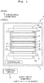
- the printing apparatus 1 includes a casing 2, a platen 3, four head bars 4, two conveyance rollers 5A and 5B, an encoder 6, and a controller 7.
- the platen 3 is placed horizontal in the casing 2. On the upper surface of the platen 3, the sheet 100 is placed.
- the four head bars 4 are provided above the platen 3 to align in the front/rear direction.
- the two conveyance rollers 5A and 5B are arranged respectively at the front side and the rear side of the platen 3.
- the two conveyance rollers 5A and 5B are driven respectively by an unshown motor to convey the sheet 100 on the platen 3 frontward. That is, the front side of the printing apparatus 1 is the upstream side in the conveyance direction whereas the rear side is the downstream side in the conveyance direction.
- the encoder 6 is provided at the conveyance roller 5A on the upstream side in the conveyance direction.
- the controller 7 includes non-volatile memories and the like such as a number of FPGAs (Field Programmable Gate Array; see Fig. 4 ), a ROM (Read Only Memory), a RAM (Random Access Memory), an EEPROM (Electrically Erasable Programmable Read-Only Memory), and the like. Note that the ROM, RAM, EEPROM and the like are unshown. Further, the controller 7 is connected with an external device 9 such as a PC or the like in a data communicable manner, to control every part of the printing apparatus 1 on the basis of print data sent from the external device 9.
- an external device 9 such as a PC or the like in a data communicable manner
- the controller 7 controls the motor driving the conveyance rollers 5A and 5B to convey the sheet 100 in the conveyance direction with the conveyance rollers 5A and 5B. Further, the controller 7 controls the head bars 4 to jet an ink to the sheet 100. By virtue of this, an image is printed on the sheet 100.
- the sheet 100 may be a roll-like sheet composed of a supply roll including the upstream end in the conveyance direction and a retrieval roll including the downstream end in the conveyance direction.
- the supply roll may be fitted on the conveyance roller 5A at the upstream side in the conveyance direction, and the retrieval roll be fitted on the conveyance roller 5B at the downstream side in the conveyance direction.
- the roll-like sheet may only have the supply roll including the upstream end in the conveyance direction. In such a case, the supply roll may be fitted on the conveyance roller 5A at the upstream side in the conveyance direction.
- a number of head retainers 8 are fitted on the casing 2.
- the head retainers 8 are provided to align in the front/rear direction, and positioned above the platen 3 and between the two conveyance rollers 5A and 5B.
- the head retainers 8 retain the head bars 4 respectively.
- the four head bars 4 jet the ink of four colors: cyan (C), magenta (M), yellow (Y), and black (K), respectively.
- Each of the head bars 4 is supplied with the ink of the corresponding color from an unsown ink tank.
- each of the head bars 4 includes a plate-like holder 10 elongated in the sheet width direction, a number of heads 11 fitted on the holder 10, and a reservoir 12.
- Each head 11 includes aftermentioned piezoelectric bodies 11b (see Fig. 6 ).
- the respective heads 11 are aligned along the sheet width direction which is the longitudinal direction of the head bar 4 to form a first head array 81 and a second head array 82.
- the first head array 81 and the second head array 82 are aligned in the conveyance direction, and the first head array 81 is positioned on the rear side of the second head array 82.
- the left end of each of the heads 11 of the first head array 81 is positioned at the same level in the left/right direction as the right end of one head 11 of the second head array 82. In other words, the left end of each of the heads 11 of the first head array 81 overlaps in the front/rear direction with the right end of one head 11 of the second head array 82.
- the holder 10 is provided with a slit 10a.
- the heads 11 are connected with the controller 7 via a flexible substrate 51 which is inserted through the slit 10a.
- the heads 11 are arranged along an arrangement direction which is the sheet width direction.
- the heads 11 are arranged to separate alternately between the front side and the rear side in the conveyance direction. Between the heads 11 arranged on the front side and the heads 11 arranged on the rear side, there is positional deviation in the left/right direction (the arrangement direction).
- the heads 11 are arranged along a direction orthogonal to the conveyance direction (along the sheet width direction).
- the heads 11 may be arranged along a direction intersecting the conveyance direction at any angle other than 90 degrees, that is, obliquely.
- the reservoir 12 is provided above the multiple heads 11. Note that Fig. 3 omits illustration of the reservoir 12.
- the reservoir 12 is connected to the ink tank (not shown) via a tube 16 to temporarily retain the ink supplied from the ink tank.
- a lower part of the reservoir 12 is connected to the multiple heads 11 to supply the ink to the respective heads 11 from the reservoir 12.
- the controller 7 includes a first substrate 71 and a number of second substrates 72.
- the first substrate 71 is provided with an FPGA 71a.
- Each second substrate 72 is provided with one FPGA 72a.
- the FPGA 71a is connected respectively to the multiple FPGAs 72a to control the driving of the FPGAs 72a.
- the FPGAs 72a correspond respectively to the heads 11, and the number of the FPGAs 72a is the same as the number of the heads 11.
- the FPGAs 72a are connected respectively with the heads 11.
- the FPGA 71a and the FPGAs 72a are connected to the RAM (not shown) functioning as a memory and the ROM (not shown) storing bit stream information.
- Each of the heads 11 includes a substrate 11c and, on the substrate 11c are mounted a removable connector 11d, a non-volatile memory 11e, and a driver IC 11f. Each head 11 is connected to one second substrate 72 in a removable manner via the connector 11d.
- the driver IC 11f includes an aftermentioned switch circuit 27. Each driver IC 11f outputs a pulse signal as a drive signal to each of the nozzles 11a. Note that each of the output voltages of a first power circuit 21 to a fifth power circuit 25 is changed based on a jetting frequency as will be described later on, but the rise position and the fall position of the drive signal outputted from the driver IC 11f are not changed before and after the output voltage is changed.
- the second substrate 72 is provided with a D/A (Digital/Analog) converter 20. Further, the second substrate 72 is provided with a number of power circuits and, in this embodiment, a first power circuit 21 to a sixth power circuit 26 are provided.
- the first power circuit 21 to the sixth power circuit 26 have FETs, electrical resistances and the like, and are capable of changing the output voltages. Switch-type DC/DC converters, for example, may be used as these first power circuit 21 to sixth power circuit 26.
- the FPGA 72a outputs a signal for setting the output voltages to the first power circuit 21 to the sixth power circuit 26 via the D/A converter 20.
- the first power circuit 21 to the sixth power circuit 26 are connected to a first power supply wire 34(1) to an nth power supply wire 34(n) (n is a natural number larger than one) via the switch circuit 27.
- the switch circuit 27 connects each of the first power supply wire 34(1) to the nth power supply wire 34(n) to any one of the first power circuit 21 to the sixth power circuit 26.
- the first power circuit 21 to the fifth power circuit 25 are ordinary power circuits for ordinary usage.
- the sixth power circuit 26 is a specially devised power circuit.
- the sixth power circuit 26 is used as, for example, a power supply voltage for VCOM of drive elements, and an HVDD for a PMOS transistor 31 (the back gate voltage at the high voltage end).
- the HVDD voltage is connected to the sixth power circuit 26 at a higher output voltage than the first power circuit 21 to the fifth power circuit 25 such that no electric current may flow to the parasitic diode of the PMOS transistor 31 at the high voltage end even if a higher voltage than a source terminal 31a of the PMOS transistor 31 is applied to a drain terminal 31b.
- the printing apparatus 1 includes a number of CMOS circuits 30 to drive the nozzles 11a respectively.
- the FPGA 72a outputs a gate signal to the CMOS circuits 30 via a first control wire 33(1) to an nth control wire 33(n) (n is a natural number larger than one).
- the first control wire 33(1) to the nth control wire 33(n) correspond respectively to the first power supply wire 34(1) to the nth power supply wire 34(n). That is, the first control wire 33(1) corresponds to the first power supply wire 34(1), and the nth control wire 33(n) corresponds to the nth power supply wire 34(n).
- the FPGA 72a outputs a signal to the switch circuit 27 for connecting each of the first power supply wire 34(1) to the nth power supply wire 34(n) to any one of the first power circuit 21 to the sixth power circuit 26.
- the FPGA 72a accesses the non-volatile memory 11e as necessary.
- the non-volatile memory 11e stores a number of nozzle addresses for identifying the respective nozzles 11a, an aftermentioned table T, and the like. Note that in this embodiment, 1,680 nozzles 11a are formed in each head 11, and the 1,680 nozzles 11a form seven nozzle groups. Then, any one of the first power circuit 21 to the fifth power circuit 25 is allocated to each nozzle group. Note that the number of nozzle groups is not limited to seven, but may be any number equal to or larger than the number of power circuits.
- the CMOS circuit 30 includes a PMOS (P-type Metal-Oxide-Semiconductor) transistor 31, an NMOS (N-type Metal-Oxide-Semiconductor) transistor 32, a resistance 35, two piezoelectric bodies 11b and 11b', and the like.
- the piezoelectric bodies 11b and 11b' function as capacitors. Note that providing only a single one piezoelectric body 11b may suffice.
- the source terminal 31a of the PMOS transistor 31 is connected to any one of the first power supply wire 34(1) to the nth power supply wire 34(n).
- a source terminal 32a of an NMOS transistor 32 is connected to the ground.
- the drain terminal 31b of the PMOS transistor 31 and a drain terminal 32b of the NMOS transistor 32 are connected to one end of the resistance 35.
- the other end of the resistance 35 is connected to the other end of the one piezoelectric body 11b' and one end of the other piezoelectric body 11b.
- the one end of the one piezoelectric body 11b' is connected to the VCOM voltage, that is, the sixth power supply voltage while the other end of the other piezoelectric body 11b is connected to the ground.
- a gate terminal 31c of the PMOS transistor 31 and a gate terminal 32c of the NMOS transistor 32 are connected to any one of the first control wire 33(1) to the nth control wire 33(n) corresponding to the power supply wire connected to the source terminal 31a of the PMOS transistor 31.
- the piezoelectric body 11b is (electrically) charged and the piezoelectric body 11b' is discharged.
- the output signal at "H” is inputted from the FPGA 72a to the gate terminal 31c of the PMOS transistor 31 and the gate terminal 32c of the NMOS transistor 32, then the NMOS transistor 32 is electrically conducted such that the piezoelectric body 11b is discharged and the piezoelectric body 11b' is charged.
- the jetting speed of the ink droplets jetted from that nozzle 11a changes depending on the jetting frequency, and thus does not remain constant.
- the jetting speed increases until the jetting frequency reaches 20 kHz, but decreases until the jetting frequency reaches 50 kHz after exceeding 20 kHz. Then, after the jetting frequency exceeds 50 kHz, the jetting speed increases again. It is conceivable that this is because the jetting speed of the ink droplets also depends on the length, the cross sectional area and/or the like of the channel of the nozzle 11a. That is, as shown in Fig.
- the correlation between the jetting frequency and the jetting speed is inherent in the channel structure of the nozzle 11a such that the same correlation is also attainable in other nozzles 11a having the same channel structure as that nozzle 11a. Then, the change of the jetting speed along with change of the jetting frequency causes density unevenness of the image printed on the sheet 100. Further, generally speaking, the jetting speed of the ink droplets jetted from the nozzle 11a is in proportion to the voltage applied to the nozzle 11a.
- the jetting speed of the ink droplets jetted from the nozzle 11a is kept constant.
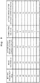
- the correction value for the voltage is, as shown in Fig. 8 , set to maintain the jetting speed of the ink at a predetermined speed at each frequency after measuring the ink jetting speed at each predetermined frequency.
- Fig. 8 shows an example of correction values for the case where the power circuit whose base voltage value is 23 V is allocated to the nozzle 11a and, at each jetting frequency, the jetting speed is kept at 10 m/s.
- the four head bars 4 are aligned in the conveyance direction, and the encoder 6 is provided at the conveyance roller 5A on the upstream side in the conveyance direction. Further, each of the head bars 4 includes multiple heads 11. Then, the sheet 100 being conveyed by the conveyance roller 5Ais accelerated. Therefore, depending on the distance from the encoder 6 in the conveyance direction, the speed of conveying the sheet 100 increases as compared to the point of time when the encoder 6 outputs the signal. Hence, if the same correction value is used in correction for the four head bars 4, then it is difficult to obtain appropriate jetting speeds for all heads 11. In this embodiment, therefore, for the heads 11 included in the head bars 4 arranged further downstream in the conveyance direction, the correction values are set larger. That is, the longer the distances between the encoder 6 and the head bars 4 in the conveyance direction, the larger the correction values set for the heads 11 included in those head bars 4.
- the table T is stored in the non-volatile memory 11e of each head 11.
- the "First" to the "Fifth" columns of the base voltage and the correction value denote the first power circuit 21 to the fifth power circuit 25, respectively.
- the table T stores the base voltage values of the first power circuit 21 to the fifth power circuit 25. Further, for each of the first power circuit 21 to the fifth power circuit 25, the correction values are associated with jetting frequencies.
- the controller 7 determines the jetting frequencies and, based on the determined jetting frequencies, changes the output voltages of the first power circuit 21 to the fifth power circuit 25 corresponding to the heads 11.
- the FPGA 71a of the first substrate 71 of the controller 7 determines the jetting frequency of each of the heads 11 based on the signal outputted from the encoder 6 denoting the conveyance speed of the sheet 100.
- an unshown non-volatile memory of the controller 7 may store a table associating the conveyance speeds of the sheet 100 with the jetting frequencies of the heads 11.
- the FPGA 71a may read out from the table the jetting frequency corresponding to the conveyance speed of the sheet 100 denoted by the signal from the encoder 6.
- the FPGA 71a may substitute into a predetermined relational expression the conveyance speed of the sheet 100 denoted by the signal from the encoder 6, to calculate the jetting frequency of the head 11.
- the FPGA 71a inputs the determined jetting frequency to the FPGA 72a of each second substrate 72.
- the FPGA 72a of each second substrate 72 refers to the table T stored in the non-volatile memory 11e of the corresponding head 11, and reads out the base voltage value of each of the first power circuit 21 to the fifth power circuit 25, and the correction value corresponding to the jetting frequency, inputted from the FPGA 71a, of each of the first power circuit 21 to the fifth power circuit 25. Then, the FPGA 72a adds the correction value to the base voltage value read out from the table T for each of the first power circuit 21 to the fifth power circuit 25 and, then, changes the output voltage to the summation of the base voltage value and the correction value. That is, the FPGA 72a outputs a signal setting the output voltage to the summation of the base voltage value and the correction value, to each of the first power circuit 21 to the fifth power circuit 25 via the D/A converter 20.
- the FPGA 72a changes the output voltage of a certain power circuit so as to maintain the average value of the jetting speed to 10 m/s of the ink droplets jetted from a certain head 11. Note that while the explanation will be made below with the third power circuit 23 as an example, much the same is true on changing the output voltage of any other power circuit as changing the output voltage of the third power circuit 23.
- the jetting frequency in the range from 40 kHz to 60 kHz, the deviation between the jetting speed of ink droplets and the target jetting speed 10 m/s becomes larger than 2 m/s. Therefore, if the jetting frequency falls in the range from 40 kHz to 60 kHz, then FPGA 72a not only changes the correction value for the third power circuit 23 depending on the jetting frequency, but also changes the base voltage value 23 V of the third power circuit 23.
- 40 kHz is an example of the second threshold value of the present teaching
- 60 kHz is an example of the third threshold value of the present teaching.
- the controller 7 may receive print data from the external device 9 and, after driving the conveyance rollers 5A and 5B but before setting the jetting frequency to 20 kHz, inputs a drive signal for maintaining the heads 11 to carry out a maintenance process for the heads 11.
- the controller 7 may start a print process based on the received print data.
- 20 kHz is an example of the first threshold value of the present teaching.
- the controller 7 may still carry out the maintenance process and, after setting the jetting frequency to 60 kHz, restart the print process based on the received print data.
- the maintenance process includes a so-called flushing process, and/or a non-jet flushing process to vibrate the meniscuses without jetting the ink in the nozzles 11a.
- the controller 7 sets or determines the jetting frequency for each head 11 on the basis of the signal outputted from the encoder 6. Then, for each of the power circuits 21 to 25 corresponding respectively to the heads 11, the output voltage is changed based on the base voltage value read out from the non-volatile memory 11e and the correction value corresponding to the determined jetting frequency.
- a signal is inputted from the encoder 6 to the FPGA 71a of the first substrate 71 and, based on the signal from the encoder 6, the jetting frequency is determined for each head 11.
- the signal may be inputted from the encoder 6 to the FPGA 72a of each second substrate 72, such that the FPGA 72a may determine the jetting frequency for the corresponding head 11 on the basis of the signal from the encoder 6.
- the encoder 6 is provided at the conveyance roller 5A on the upstream side in the conveyance direction.
- the encoder 6 may be provided at the conveyance roller 5B on the downstream side in the conveyance direction.
- the FPGA 72a of each second substrate 72 changes the output voltage by adding a correction value to the base voltage value read out from the table T for each of the first power circuit 21 to the fifth power circuit 25.
- a thermistor may be provided for detecting the temperature of each head 11, and the non-volatile memory 11e of each head 11 may further store second correction values corresponding to the temperatures.
- the second correction values may be set smaller as the temperature of the head 11 detected by the thermistor rises.
- the FPGA 72a may change the output voltage based on the second correction value, the correction value, and the base voltage value read out from the table T, for each of the first power circuit 21 to the fifth power circuit 25.
- the non-volatile memory 11e of each head 11 may store another second correction values corresponding to printing rates.
- the FPGA 71a of the first substrate 71 may calculate the printing rate of each head 11 on the basis of the print data inputted from the external device 9, and then input the same to the FPGA 72a of each second substrate 72.
- the second correction values may be set smaller as the printing rate of the head 11 rises.
- the FPGA 72a may change the output voltage based on this second correction value, the correction value, and the base voltage value read out from the table T, for each of the first power circuit 21 to the fifth power circuit 25.
- the FPGA 72a of each second substrate 72 changes the output voltage of each of the first power circuit 21 to the fifth power circuit 25 depending on the jetting frequency determined by the FPGA 71a of the first substrate 71.
- the FPGA 72a may not change the output voltage of each of the first power circuit 21 to the fifth power circuit 25 depending on the jetting frequency determined by the FPGA 71a of the first substrate 71, but may change the allocation of power circuit to each nozzle group.
- the jetting speed of ink droplets is maintained at 10 m/s.
- the jetting speed of ink droplets may be maintained at 9 m/s or 11 m/s.
Landscapes
- Engineering & Computer Science (AREA)
- Quality & Reliability (AREA)
- Ink Jet (AREA)
Abstract
Description
- The present invention relates to a printing apparatus which jets ink from nozzles.
- There is known an ink jet printer including a motor driving a print object, a head jetting ink to the print object driven by the motor, and an encoder provided for the motor (see Japanese Patent Application Laid-open No.
10-151774 - However, if the jetting frequency of the head is changed based on the speed of the print object, then the jetting speed of the liquid jetted from the head will change depending on the jetting frequency of the head, so as to cause a problem that density unevenness arises in the image printed on the print object.
- An object of the present teaching is to provide a printing apparatus where the jetting frequency of the head is changed based on the speed of a print object, and the density unevenness is made less likely to arise in an image being printed on the print obj ect.
- According to a first aspect of the present teaching, there is provided a printing apparatus including: a conveyance roller configured to convey a sheet in a first direction; an encoder provided at the conveyance roller; a head having a plurality of nozzles aligned in a second direction intersecting with the first direction, and being configured to jet liquid to the sheet which is conveyed in the first direction by the conveyance roller; and a controller having a power circuit configured to apply voltage to the head for jetting the liquid, wherein the controller is configured to: determine a jetting frequency for the head based on a signal outputted from the encoder; and change an output voltage of the power circuit depending on the determined jetting frequency.
- According to a second aspect of the present teaching, there is provided a printing apparatus including: a conveyance roller configured to convey a sheet in a first direction; an encoder provided at the conveyance roller; a first head bar including a plurality of first heads configured to jet first liquid to the sheet which is conveyed in the first direction by the conveyance roller; and a controller having a first power circuit configured to apply voltage to each of the first heads for jetting the first liquid, wherein each of the first heads has a plurality of nozzles aligned in a second direction intersecting with the first direction, and the controller is configured to: determine a jetting frequency for each of the first heads based on a signal outputted from the encoder; and change an output voltage of the first power circuit depending on the determined jetting frequency.
- According to a third aspect of the present teaching, there is provided a printing apparatus including: a conveyance roller configured to convey a sheet in a first direction; an encoder provided at the conveyance roller; a head having a plurality of nozzles aligned in a second direction intersecting with the first direction, and being configured to jet liquid to the sheet which is conveyed in the first direction by the conveyance roller; and a controller including a plurality of power circuits configured to apply voltage to the head for jetting the liquid, wherein a plurality of nozzle groups are formed in the head, the number of the power circuits is equal to or less than the number of the nozzle groups, any one of the power circuits is allocated to each of the nozzle groups, and the controller is configured to: determine a jetting frequency for the head based on a signal outputted from the encoder; and change allocation of the power circuits to the nozzle groups depending on the determined jetting frequency.
- In the printing apparatus according to the first to the third aspects of the present teaching, the controller is configured to determine the jetting frequency for the head based on the signal outputted from the encoder and, depending on the determined jetting frequency, either change the output voltage of the power circuit or change the allocation of the power circuits to the nozzle groups. Therefore, it is possible to maintain a constant jetting speed of droplets jetted from the nozzles independently from the jetting frequency, such that density unevenness is made less likely to arise in an image being printed on the sheet.
-
-
Fig. 1 is a plan view schematically showing a printing apparatus according to an embodiment of the present teaching. -
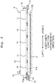
Fig. 2 is a cross section view along the line II-II shown inFig. 1 . -
Fig. 3 is a bottom view of a head bar. -
Fig. 4 is a block diagram schematically showing a connection of a controller and heads. -
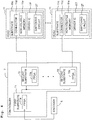
Fig. 5 is a block diagram schematically showing a configuration of the vicinity of a power source. -
Fig. 6 is a circuit diagram schematically showing a configuration of a CMOS (Complementary Metal-Oxide-Semiconductor) circuit driving nozzles. -
Fig. 7 is a graph showing a relationship between a jetting frequency and a jetting speed of ink droplets jetted from the nozzles, when a constant voltage is applied to a piezoelectric body. -
Fig. 8 is a table showing an example of a correction value for the voltage set according to each jetting frequency. -
Fig. 9 is an exemplary table stored in a non-volatile memory. - Hereinbelow, referring to
Figs. 1 to 9 , an explanation will be made on a printing apparatus according to an embodiment of the present teaching. - In
Fig. 1 , the upstream side of asheet 100 in a conveyance direction is defined as the front side of aprinting apparatus 1, whereas the downstream side in the conveyance direction is defined as the rear side of theprinting apparatus 1. Further, a left/right direction of theprinting apparatus 1 is defined as a sheet width direction being orthogonal to the conveyance direction and parallel to the surface of thesheet 100 being conveyed (the surface parallel to the page surface ofFig. 1 ). Note that the left side of the figure is the left side of theprinting apparatus 1 whereas the right side of the figure is the right side of theprinting apparatus 1. Further, an up/down direction of theprinting apparatus 1 is defined as the direction orthogonal to the conveyance surface of the sheet 100 (the direction orthogonal to the page surface ofFig. 1 ). InFig. 1 , the page front side is the upside whereas the page back side is the downside. Hereinbelow, the front, rear, left, right, up (or upper), and down (or lower) will be used appropriately for the explanation. - As shown in
Fig. 1 , theprinting apparatus 1 includes acasing 2, aplaten 3, fourhead bars 4, twoconveyance rollers encoder 6, and acontroller 7. - The
platen 3 is placed horizontal in thecasing 2. On the upper surface of theplaten 3, thesheet 100 is placed. The fourhead bars 4 are provided above theplaten 3 to align in the front/rear direction. The twoconveyance rollers platen 3. The twoconveyance rollers sheet 100 on theplaten 3 frontward. That is, the front side of theprinting apparatus 1 is the upstream side in the conveyance direction whereas the rear side is the downstream side in the conveyance direction. Theencoder 6 is provided at theconveyance roller 5A on the upstream side in the conveyance direction. - The
controller 7 includes non-volatile memories and the like such as a number of FPGAs (Field Programmable Gate Array; seeFig. 4 ), a ROM (Read Only Memory), a RAM (Random Access Memory), an EEPROM (Electrically Erasable Programmable Read-Only Memory), and the like. Note that the ROM, RAM, EEPROM and the like are unshown. Further, thecontroller 7 is connected with anexternal device 9 such as a PC or the like in a data communicable manner, to control every part of theprinting apparatus 1 on the basis of print data sent from theexternal device 9. - For example, the
controller 7 controls the motor driving theconveyance rollers sheet 100 in the conveyance direction with theconveyance rollers controller 7 controls thehead bars 4 to jet an ink to thesheet 100. By virtue of this, an image is printed on thesheet 100. Note that thesheet 100 may be a roll-like sheet composed of a supply roll including the upstream end in the conveyance direction and a retrieval roll including the downstream end in the conveyance direction. In such a case, the supply roll may be fitted on theconveyance roller 5A at the upstream side in the conveyance direction, and the retrieval roll be fitted on theconveyance roller 5B at the downstream side in the conveyance direction. Alternatively, the roll-like sheet may only have the supply roll including the upstream end in the conveyance direction. In such a case, the supply roll may be fitted on theconveyance roller 5A at the upstream side in the conveyance direction. - A number of
head retainers 8 are fitted on thecasing 2. Thehead retainers 8 are provided to align in the front/rear direction, and positioned above theplaten 3 and between the twoconveyance rollers head retainers 8 retain thehead bars 4 respectively. - The four
head bars 4 jet the ink of four colors: cyan (C), magenta (M), yellow (Y), and black (K), respectively. Each of thehead bars 4 is supplied with the ink of the corresponding color from an unsown ink tank. - As shown in
Figs. 2 and3 , each of thehead bars 4 includes a plate-like holder 10 elongated in the sheet width direction, a number ofheads 11 fitted on theholder 10, and areservoir 12. - A number of
nozzles 11a are formed in the lower surface of eachhead 11. Eachhead 11 includes aftermentionedpiezoelectric bodies 11b (seeFig. 6 ). Therespective heads 11 are aligned along the sheet width direction which is the longitudinal direction of thehead bar 4 to form afirst head array 81 and a second head array 82. Thefirst head array 81 and the second head array 82 are aligned in the conveyance direction, and thefirst head array 81 is positioned on the rear side of the second head array 82. - As shown in
Fig. 3 , the left end of each of theheads 11 of thefirst head array 81 is positioned at the same level in the left/right direction as the right end of onehead 11 of the second head array 82. In other words, the left end of each of theheads 11 of thefirst head array 81 overlaps in the front/rear direction with the right end of onehead 11 of the second head array 82. - As shown in
Fig. 2 , theholder 10 is provided with aslit 10a. Theheads 11 are connected with thecontroller 7 via aflexible substrate 51 which is inserted through theslit 10a. - The
heads 11 are arranged along an arrangement direction which is the sheet width direction. Theheads 11 are arranged to separate alternately between the front side and the rear side in the conveyance direction. Between theheads 11 arranged on the front side and theheads 11 arranged on the rear side, there is positional deviation in the left/right direction (the arrangement direction). Note that in this embodiment, theheads 11 are arranged along a direction orthogonal to the conveyance direction (along the sheet width direction). However, theheads 11 may be arranged along a direction intersecting the conveyance direction at any angle other than 90 degrees, that is, obliquely. - As shown in
Figs. 1 and2 , thereservoir 12 is provided above the multiple heads 11. Note thatFig. 3 omits illustration of thereservoir 12. - The
reservoir 12 is connected to the ink tank (not shown) via atube 16 to temporarily retain the ink supplied from the ink tank. A lower part of thereservoir 12 is connected to themultiple heads 11 to supply the ink to therespective heads 11 from thereservoir 12. - As shown in
Fig. 4 , thecontroller 7 includes afirst substrate 71 and a number ofsecond substrates 72. Thefirst substrate 71 is provided with anFPGA 71a. Eachsecond substrate 72 is provided with oneFPGA 72a. TheFPGA 71a is connected respectively to themultiple FPGAs 72a to control the driving of theFPGAs 72a. TheFPGAs 72a correspond respectively to theheads 11, and the number of theFPGAs 72a is the same as the number of theheads 11. TheFPGAs 72a are connected respectively with theheads 11. TheFPGA 71a and theFPGAs 72a are connected to the RAM (not shown) functioning as a memory and the ROM (not shown) storing bit stream information. - Each of the
heads 11 includes asubstrate 11c and, on thesubstrate 11c are mounted aremovable connector 11d, anon-volatile memory 11e, and adriver IC 11f. Eachhead 11 is connected to onesecond substrate 72 in a removable manner via theconnector 11d. Thedriver IC 11f includes anaftermentioned switch circuit 27. Eachdriver IC 11f outputs a pulse signal as a drive signal to each of thenozzles 11a. Note that each of the output voltages of a first power circuit 21 to afifth power circuit 25 is changed based on a jetting frequency as will be described later on, but the rise position and the fall position of the drive signal outputted from thedriver IC 11f are not changed before and after the output voltage is changed. - As shown in
Fig. 5 , thesecond substrate 72 is provided with a D/A (Digital/Analog)converter 20. Further, thesecond substrate 72 is provided with a number of power circuits and, in this embodiment, a first power circuit 21 to asixth power circuit 26 are provided. The first power circuit 21 to thesixth power circuit 26 have FETs, electrical resistances and the like, and are capable of changing the output voltages. Switch-type DC/DC converters, for example, may be used as these first power circuit 21 tosixth power circuit 26. TheFPGA 72a outputs a signal for setting the output voltages to the first power circuit 21 to thesixth power circuit 26 via the D/A converter 20. - The first power circuit 21 to the
sixth power circuit 26 are connected to a first power supply wire 34(1) to an nth power supply wire 34(n) (n is a natural number larger than one) via theswitch circuit 27. Theswitch circuit 27 connects each of the first power supply wire 34(1) to the nth power supply wire 34(n) to any one of the first power circuit 21 to thesixth power circuit 26. The first power circuit 21 to thefifth power circuit 25 are ordinary power circuits for ordinary usage. Thesixth power circuit 26 is a specially devised power circuit. Thesixth power circuit 26 is used as, for example, a power supply voltage for VCOM of drive elements, and an HVDD for a PMOS transistor 31 (the back gate voltage at the high voltage end). - The HVDD voltage is connected to the
sixth power circuit 26 at a higher output voltage than the first power circuit 21 to thefifth power circuit 25 such that no electric current may flow to the parasitic diode of thePMOS transistor 31 at the high voltage end even if a higher voltage than a source terminal 31a of thePMOS transistor 31 is applied to adrain terminal 31b. - As shown in
Fig. 6 , theprinting apparatus 1 includes a number ofCMOS circuits 30 to drive thenozzles 11a respectively. TheFPGA 72a outputs a gate signal to theCMOS circuits 30 via a first control wire 33(1) to an nth control wire 33(n) (n is a natural number larger than one). Note that the first control wire 33(1) to the nth control wire 33(n) correspond respectively to the first power supply wire 34(1) to the nth power supply wire 34(n). That is, the first control wire 33(1) corresponds to the first power supply wire 34(1), and the nth control wire 33(n) corresponds to the nth power supply wire 34(n). - The
FPGA 72a outputs a signal to theswitch circuit 27 for connecting each of the first power supply wire 34(1) to the nth power supply wire 34(n) to any one of the first power circuit 21 to thesixth power circuit 26. TheFPGA 72a accesses thenon-volatile memory 11e as necessary. Thenon-volatile memory 11e stores a number of nozzle addresses for identifying therespective nozzles 11a, an aftermentioned table T, and the like. Note that in this embodiment, 1,680nozzles 11a are formed in eachhead 11, and the 1,680nozzles 11a form seven nozzle groups. Then, any one of the first power circuit 21 to thefifth power circuit 25 is allocated to each nozzle group. Note that the number of nozzle groups is not limited to seven, but may be any number equal to or larger than the number of power circuits. - As shown in
Fig. 6 , theCMOS circuit 30 includes a PMOS (P-type Metal-Oxide-Semiconductor)transistor 31, an NMOS (N-type Metal-Oxide-Semiconductor)transistor 32, aresistance 35, twopiezoelectric bodies piezoelectric bodies piezoelectric body 11b may suffice. The source terminal 31a of thePMOS transistor 31 is connected to any one of the first power supply wire 34(1) to the nth power supply wire 34(n). Asource terminal 32a of anNMOS transistor 32 is connected to the ground. - The
drain terminal 31b of thePMOS transistor 31 and adrain terminal 32b of theNMOS transistor 32 are connected to one end of theresistance 35. The other end of theresistance 35 is connected to the other end of the onepiezoelectric body 11b' and one end of the otherpiezoelectric body 11b. The one end of the onepiezoelectric body 11b' is connected to the VCOM voltage, that is, the sixth power supply voltage while the other end of the otherpiezoelectric body 11b is connected to the ground. - A
gate terminal 31c of thePMOS transistor 31 and agate terminal 32c of theNMOS transistor 32 are connected to any one of the first control wire 33(1) to the nth control wire 33(n) corresponding to the power supply wire connected to the source terminal 31a of thePMOS transistor 31. - If the output signal at "L" is inputted from the
FPGA 72a to thegate terminal 31c of thePMOS transistor 31 and thegate terminal 32c of theNMOS transistor 32, then thePMOS transistor 31 is electrically conducted such that thepiezoelectric body 11b is (electrically) charged and thepiezoelectric body 11b' is discharged. If the output signal at "H" is inputted from theFPGA 72a to thegate terminal 31c of thePMOS transistor 31 and thegate terminal 32c of theNMOS transistor 32, then theNMOS transistor 32 is electrically conducted such that thepiezoelectric body 11b is discharged and thepiezoelectric body 11b' is charged. By electrically charging and discharging thepiezoelectric bodies piezoelectric bodies nozzles 11a. - Next, referring to
Fig. 7 , an explanation will be made on a relationship between the jetting frequency and the jetting speed of the ink droplets jetted from acertain nozzle 11a, when a constant voltage is applied to thepiezoelectric bodies certain nozzle 11a. - As shown in
Fig. 7 , even if the constant voltage is applied to thecertain nozzle 11a, the jetting speed of the ink droplets jetted from thatnozzle 11a changes depending on the jetting frequency, and thus does not remain constant. In the example ofFig. 7 , the jetting speed increases until the jetting frequency reaches 20 kHz, but decreases until the jetting frequency reaches 50 kHz after exceeding 20 kHz. Then, after the jetting frequency exceeds 50 kHz, the jetting speed increases again. It is conceivable that this is because the jetting speed of the ink droplets also depends on the length, the cross sectional area and/or the like of the channel of thenozzle 11a. That is, as shown inFig. 7 , the correlation between the jetting frequency and the jetting speed is inherent in the channel structure of thenozzle 11a such that the same correlation is also attainable inother nozzles 11a having the same channel structure as thatnozzle 11a. Then, the change of the jetting speed along with change of the jetting frequency causes density unevenness of the image printed on thesheet 100. Further, generally speaking, the jetting speed of the ink droplets jetted from thenozzle 11a is in proportion to the voltage applied to thenozzle 11a. - In this embodiment, therefore, by correcting the voltage applied to the
nozzle 11a depending on the jetting frequency, the jetting speed of the ink droplets jetted from thenozzle 11a is kept constant. The correction value for the voltage is, as shown inFig. 8 , set to maintain the jetting speed of the ink at a predetermined speed at each frequency after measuring the ink jetting speed at each predetermined frequency.Fig. 8 shows an example of correction values for the case where the power circuit whose base voltage value is 23 V is allocated to thenozzle 11a and, at each jetting frequency, the jetting speed is kept at 10 m/s. - Note that in this embodiment, the four
head bars 4 are aligned in the conveyance direction, and theencoder 6 is provided at theconveyance roller 5A on the upstream side in the conveyance direction. Further, each of the head bars 4 includes multiple heads 11. Then, thesheet 100 being conveyed by the conveyance roller 5Ais accelerated. Therefore, depending on the distance from theencoder 6 in the conveyance direction, the speed of conveying thesheet 100 increases as compared to the point of time when theencoder 6 outputs the signal. Hence, if the same correction value is used in correction for the fourhead bars 4, then it is difficult to obtain appropriate jetting speeds for all heads 11. In this embodiment, therefore, for theheads 11 included in the head bars 4 arranged further downstream in the conveyance direction, the correction values are set larger. That is, the longer the distances between theencoder 6 and the head bars 4 in the conveyance direction, the larger the correction values set for theheads 11 included in those head bars 4. - Then, as shown in
Fig. 9 , the table T is stored in thenon-volatile memory 11e of eachhead 11. Note that inFig. 9 , the "First" to the "Fifth" columns of the base voltage and the correction value denote the first power circuit 21 to thefifth power circuit 25, respectively. The table T stores the base voltage values of the first power circuit 21 to thefifth power circuit 25. Further, for each of the first power circuit 21 to thefifth power circuit 25, the correction values are associated with jetting frequencies. - Next, an explanation will be made on a procedure where for the
respective heads 11, thecontroller 7 determines the jetting frequencies and, based on the determined jetting frequencies, changes the output voltages of the first power circuit 21 to thefifth power circuit 25 corresponding to theheads 11. - First, the
FPGA 71a of thefirst substrate 71 of thecontroller 7 determines the jetting frequency of each of theheads 11 based on the signal outputted from theencoder 6 denoting the conveyance speed of thesheet 100. For example, an unshown non-volatile memory of thecontroller 7 may store a table associating the conveyance speeds of thesheet 100 with the jetting frequencies of theheads 11. Then, theFPGA 71a may read out from the table the jetting frequency corresponding to the conveyance speed of thesheet 100 denoted by the signal from theencoder 6. Alternatively, theFPGA 71a may substitute into a predetermined relational expression the conveyance speed of thesheet 100 denoted by the signal from theencoder 6, to calculate the jetting frequency of thehead 11. Then, theFPGA 71a inputs the determined jetting frequency to theFPGA 72a of eachsecond substrate 72. - Next, the
FPGA 72a of eachsecond substrate 72 refers to the table T stored in thenon-volatile memory 11e of the correspondinghead 11, and reads out the base voltage value of each of the first power circuit 21 to thefifth power circuit 25, and the correction value corresponding to the jetting frequency, inputted from theFPGA 71a, of each of the first power circuit 21 to thefifth power circuit 25. Then, theFPGA 72a adds the correction value to the base voltage value read out from the table T for each of the first power circuit 21 to thefifth power circuit 25 and, then, changes the output voltage to the summation of the base voltage value and the correction value. That is, theFPGA 72a outputs a signal setting the output voltage to the summation of the base voltage value and the correction value, to each of the first power circuit 21 to thefifth power circuit 25 via the D/A converter 20. - Next, an explanation will be made on a particular example where if the jetting frequency changes between 0 kHz and 80 kHz, then the
FPGA 72a changes the output voltage of a certain power circuit so as to maintain the average value of the jetting speed to 10 m/s of the ink droplets jetted from acertain head 11. Note that while the explanation will be made below with thethird power circuit 23 as an example, much the same is true on changing the output voltage of any other power circuit as changing the output voltage of thethird power circuit 23. - As shown in
Fig. 7 , with the jetting frequency in the range from 0 kHz to 40 kHz and from 60 kHz to 80 kHz, the deviation between the jetting speed of ink droplets and the target jetting speed 10 m/s lies within 2 m/s. Therefore, if the jetting frequency stays within the range from 0 kHz to 40 kHz and from 60 kHz to 80 kHz, thenFPGA 72a does not change the base voltage value 23 V of thethird power circuit 23 but only changes the correction value depending on the jetting frequency. - On the other hand, with the jetting frequency in the range from 40 kHz to 60 kHz, the deviation between the jetting speed of ink droplets and the target jetting speed 10 m/s becomes larger than 2 m/s. Therefore, if the jetting frequency falls in the range from 40 kHz to 60 kHz, then FPGA 72a not only changes the correction value for the
third power circuit 23 depending on the jetting frequency, but also changes the base voltage value 23 V of thethird power circuit 23. In this case, 40 kHz is an example of the second threshold value of the present teaching, and 60 kHz is an example of the third threshold value of the present teaching. - Note that the
controller 7 may receive print data from theexternal device 9 and, after driving theconveyance rollers heads 11 to carry out a maintenance process for theheads 11. On setting the jetting frequency to 20 kHz, thecontroller 7 may start a print process based on the received print data. In this case, 20 kHz is an example of the first threshold value of the present teaching. Further, with the jetting frequency in the range from 40 kHz to 60 kHz, thecontroller 7 may still carry out the maintenance process and, after setting the jetting frequency to 60 kHz, restart the print process based on the received print data. Note that the maintenance process includes a so-called flushing process, and/or a non-jet flushing process to vibrate the meniscuses without jetting the ink in thenozzles 11a. - According to the embodiment of the present teaching explained above, the
controller 7 sets or determines the jetting frequency for eachhead 11 on the basis of the signal outputted from theencoder 6. Then, for each of the power circuits 21 to 25 corresponding respectively to theheads 11, the output voltage is changed based on the base voltage value read out from thenon-volatile memory 11e and the correction value corresponding to the determined jetting frequency. By virtue of this, it is possible to maintain a constant jetting speed of the ink droplets independently from the jetting frequency, such that density unevenness can be made less likely to arise in the image being printed on thesheet 100. - Hereinabove, one embodiment of the present teaching was explained. However, the present teaching is not limited to the above embodiment but can undergo various design changes without departing from the scope set forth in the appended claims.
- In this embodiment, a signal is inputted from the
encoder 6 to theFPGA 71a of thefirst substrate 71 and, based on the signal from theencoder 6, the jetting frequency is determined for eachhead 11. However, without being limited to that, for example, the signal may be inputted from theencoder 6 to theFPGA 72a of eachsecond substrate 72, such that theFPGA 72a may determine the jetting frequency for the correspondinghead 11 on the basis of the signal from theencoder 6. - In this embodiment, the
encoder 6 is provided at theconveyance roller 5A on the upstream side in the conveyance direction. However, theencoder 6 may be provided at theconveyance roller 5B on the downstream side in the conveyance direction. - In this embodiment, the
FPGA 72a of eachsecond substrate 72 changes the output voltage by adding a correction value to the base voltage value read out from the table T for each of the first power circuit 21 to thefifth power circuit 25. However, without being limited to that, for example, a thermistor may be provided for detecting the temperature of eachhead 11, and thenon-volatile memory 11e of eachhead 11 may further store second correction values corresponding to the temperatures. Generally speaking, the higher the temperature of thehead 11, the lower the viscosity of the ink in thehead 11. Then, the lower the viscosity of the ink, the faster the jetting speed of the ink. Hence, the second correction values may be set smaller as the temperature of thehead 11 detected by the thermistor rises. Then, theFPGA 72a may change the output voltage based on the second correction value, the correction value, and the base voltage value read out from the table T, for each of the first power circuit 21 to thefifth power circuit 25. - Alternatively, the
non-volatile memory 11e of eachhead 11 may store another second correction values corresponding to printing rates. In such a case, theFPGA 71a of thefirst substrate 71 may calculate the printing rate of eachhead 11 on the basis of the print data inputted from theexternal device 9, and then input the same to theFPGA 72a of eachsecond substrate 72. Generally speaking, the higher the printing rate of thehead 11, the higher the temperature of thehead 11, such that the ink viscosity in thehead 11 is inclined to decrease. Then, the lower the ink viscosity, the faster the jetting speed of the ink. Therefore, the second correction values may be set smaller as the printing rate of thehead 11 rises. Then, theFPGA 72a may change the output voltage based on this second correction value, the correction value, and the base voltage value read out from the table T, for each of the first power circuit 21 to thefifth power circuit 25. - In this embodiment, the
FPGA 72a of eachsecond substrate 72 changes the output voltage of each of the first power circuit 21 to thefifth power circuit 25 depending on the jetting frequency determined by theFPGA 71a of thefirst substrate 71. However, without being limited to that, for example, theFPGA 72a may not change the output voltage of each of the first power circuit 21 to thefifth power circuit 25 depending on the jetting frequency determined by theFPGA 71a of thefirst substrate 71, but may change the allocation of power circuit to each nozzle group. - The above explanation was made on the correction value for the case where the jetting speed of ink droplets is maintained at 10 m/s. However, without being limited to 10 m/s, for example, the jetting speed of ink droplets may be maintained at 9 m/s or 11 m/s.
Claims (19)
- A printing apparatus comprising:a conveyance roller configured to convey a sheet in a first direction;an encoder provided at the conveyance roller;a head having a plurality of nozzles aligned in a second direction intersecting with the first direction, and being configured to jet liquid to the sheet which is conveyed in the first direction by the conveyance roller; anda controller having a power circuit configured to apply voltage to the head for jetting the liquid,wherein the controller is configured to:determine a jetting frequency for the head based on a signal outputted from the encoder; andchange an output voltage of the power circuit depending on the determined jetting frequency.
- The printing apparatus according to claim 1, wherein the controller is configured to change the output voltage of the power circuit such that jetting speed of the liquid jetted from the nozzles is kept constant between before and after the output voltage of the power circuit is changed.
- The printing apparatus according to claim 1 or 2,
wherein the head further has a memory,
a base voltage value and a plurality of correction values associated respectively with a plurality of jetting frequencies are stored in the memory, for the power circuit, and
the controller is configured to:read out, from the memory, the base voltage value and a correction value corresponding to the determined jetting frequency, for the power circuit; andchange the output voltage of the power circuit based on the base voltage value and the correction value read out from the memory. - The printing apparatus according to claim 3,
wherein the controller has a plurality of power circuits including the power circuit, and
the base voltage value and the correction values associated respectively with the jetting frequencies are stored in the memory, for each of the power circuits. - The printing apparatus according to claim 4,
wherein the head has a plurality of nozzle groups formed therein, and
the number of the power circuits is equal to or less than the number of the nozzle groups. - The printing apparatus according to claim 4,
wherein the controller is configured to:drive the conveyance roller after receiving print data;input a drive signal for maintaining the head, after driving the conveyance roller and before determining that the jetting frequency is a first threshold value; andcontrol the head to start a print process based on the print data in a case of determining that the jetting frequency is the first threshold value. - The printing apparatus according to claim 6,
wherein for each of the power circuits, the controller is configured to:change the output voltage based on the base voltage value and a first correction value corresponding to the first threshold value which are read out from the memory, in a case of determining that the jetting frequency is the first threshold value; andchange the first correction value without changing the base voltage value, after determining that the jetting frequency is the first threshold value and before determining that the jetting frequency is a second threshold value. - The printing apparatus according to claim 7,
wherein for each of the power circuits, the controller is configured to:change the base voltage value and the first correction value after determining that the jetting frequency is the second threshold value and before determining that the jetting frequency is a third threshold value; andchange only the first correction value without changing the base voltage value after determining that the jetting frequency is the third threshold value. - The printing apparatus according to claim 7,
wherein the controller is configured to:control the head to stop the print process and input the drive signal for maintaining the head after determining that the jetting frequency is the second threshold value and before determining that the jetting frequency is the third threshold value; andrestart the print process after determining that the jetting frequency is the third threshold value. - A printing apparatus comprising:a conveyance roller configured to convey a sheet in a first direction;an encoder provided at the conveyance roller;a first head bar including a plurality of first heads configured to jet first liquid to the sheet which is conveyed in the first direction by the conveyance roller; anda controller having a first power circuit configured to apply voltage to each of the first heads for jetting the first liquid,wherein each of the first heads has a plurality of nozzles aligned in a second direction intersecting with the first direction, andthe controller is configured to:determine a jetting frequency for each of the first heads based on a signal outputted from the encoder; andchange an output voltage of the first power circuit depending on the determined jetting frequency.
- The printing apparatus according to claim 10, further comprising a second head bar arranged at a position further away from the encoder than the first head bar in the first direction, and having a plurality of second heads configured to jet second liquid to the sheet which is conveyed in the first direction by the conveyance roller,
wherein the first head bar further includes a first memory, the first memory storing a plurality of correction values associated respectively with a plurality of jetting frequencies for each of the first heads,
the second head bar further includes a second memory, the second memory storing a plurality of correction values associated respectively with a plurality of jetting frequencies for each of the second heads, and
the correction values stored in the second memory are larger than the correction values stored in the first memory. - The printing apparatus according to claim 11,
wherein each of the second heads has a plurality of nozzles aligned in the second direction,
the controller further includes a second power circuit configured to apply voltage to each of the second heads for jetting the second liquid, and
the controller is further configured to change an output voltage of the second power circuit according to the determined jetting frequency. - The printing apparatus according to claim 12,
wherein the sheet has a supply roll including an upstream end of the sheet in the first direction and a retrieval roll including a downstream end of the sheet in the first direction,
the conveyance roller has a supply roller which is arranged further upstream than the first heads and the second heads in the first direction and at which the supply roll is fitted and a retrieval roller arranged further downstream than the first heads and the second heads in the first direction and at which the retrieval roll is fitted, and
the encoder is provided at the supply roller. - The printing apparatus according to claim 3, further comprising a thermistor configured to detect the temperature of the head,
wherein the memory stores a plurality of second correction values associated respectively with temperatures, for the power circuit, and
the controller is configured to:read out, from the memory, the base voltage value of the power circuit, the correction value corresponding to the jetting frequency determined, and a second correction value corresponding to a temperature of the head detected by the thermistor; andchange the output voltage of the power circuit based on the base voltage value, the correction value and the second correction value read out from the memory. - The printing apparatus according to claim 14, wherein the second correction values are set to be smaller as the temperature of the head detected by the thermistor rises.
- The printing apparatus according to claim 3,
wherein the controller is configured to calculate a printing rate of the head based on print data,
the memory stores a plurality of second correction values associated with printing rates, for the power circuit, and
the controller is configured to:read out, from the memory, the base voltage value of the power circuit, the correction value corresponding to the jetting frequency determined, and a second correction value corresponding to the printing rate calculated; andchange the output voltage of the power circuit based on the base voltage value, the correction value and the second correction value read out from the memory. - The printing apparatus according to claim 16, wherein the second correction values are set to be smaller as the printing rate rises.
- The printing apparatus according to claim 1,
wherein the controller is configured to input a pulse drive signal to the head to drive each of the nozzles, and
a rise position and a fall position of the pulse drive signal before the output voltage of the power circuit is changed are respectively same as a rise position and a fall position of the pulse drive signal after the output voltage of the power circuit is changed. - A printing apparatus comprising:a conveyance roller configured to convey a sheet in a first direction;an encoder provided at the conveyance roller;a head having a plurality of nozzles aligned in a second direction intersecting with the first direction, and being configured to jet liquid to the sheet which is conveyed in the first direction by the conveyance roller; anda controller including a plurality of power circuits configured to apply voltage to the head for jetting the liquid,wherein a plurality of nozzle groups are formed in the head,the number of the power circuits is equal to or less than the number of the nozzle groups,any one of the power circuits is allocated to each of the nozzle groups, andthe controller is configured to:determine a jetting frequency for the head based on a signal outputted from the encoder; andchange allocation of the power circuits to the nozzle groups depending on the determined jetting frequency.
Applications Claiming Priority (1)
| Application Number | Priority Date | Filing Date | Title |
|---|---|---|---|
| JP2019066482A JP7500921B2 (en) | 2019-03-29 | 2019-03-29 | Printing device |
Publications (2)
| Publication Number | Publication Date |
|---|---|
| EP3825128A1 true EP3825128A1 (en) | 2021-05-26 |
| EP3825128B1 EP3825128B1 (en) | 2023-07-12 |
Family
ID=69810629
Family Applications (1)
| Application Number | Title | Priority Date | Filing Date |
|---|---|---|---|
| EP20162657.9A Active EP3825128B1 (en) | 2019-03-29 | 2020-03-12 | Printing apparatus |
Country Status (3)
| Country | Link |
|---|---|
| US (1) | US11338580B2 (en) |
| EP (1) | EP3825128B1 (en) |
| JP (1) | JP7500921B2 (en) |
Families Citing this family (1)
| Publication number | Priority date | Publication date | Assignee | Title |
|---|---|---|---|---|
| JP7615740B2 (en) * | 2021-02-17 | 2025-01-17 | 株式会社リコー | Droplet ejection device and image forming apparatus |
Citations (3)
| Publication number | Priority date | Publication date | Assignee | Title |
|---|---|---|---|---|
| JPH10151774A (en) | 1996-11-15 | 1998-06-09 | Toxot Sci & Applic | Continuous multi-color inkjet printing press, synchronization process for this printing press, and the printed product obtained using this printing press |
| EP3225399A1 (en) * | 2016-03-30 | 2017-10-04 | Brother Kogyo Kabushiki Kaisha | Printing apparatus |
| EP3381689A2 (en) * | 2017-03-31 | 2018-10-03 | Brother Kogyo Kabushiki Kaisha | Liquid jetting apparatus |
Family Cites Families (10)
| Publication number | Priority date | Publication date | Assignee | Title |
|---|---|---|---|---|
| JPS61209166A (en) | 1985-03-13 | 1986-09-17 | Sanyo Electric Co Ltd | Driving circuit for ink jet printer |
| JPH11207964A (en) | 1998-01-22 | 1999-08-03 | Kishu Giken Kogyo Kk | Driving method of piezo element in continuous ink jet printer and continuous ink jet printer |
| JP4556431B2 (en) | 2004-01-13 | 2010-10-06 | コニカミノルタホールディングス株式会社 | Inkjet printer |
| JP2007216648A (en) * | 2006-02-20 | 2007-08-30 | Seiko Epson Corp | Correcting method and compensating apparatus |
| JP2009018534A (en) | 2007-07-13 | 2009-01-29 | Canon Finetech Inc | Inkjet recording apparatus |
| JP5360354B2 (en) * | 2008-05-19 | 2013-12-04 | セイコーエプソン株式会社 | Recording device |
| JP2010120212A (en) | 2008-11-18 | 2010-06-03 | Ricoh Co Ltd | Image forming apparatus, method and program |
| JP6747017B2 (en) | 2016-03-31 | 2020-08-26 | ブラザー工業株式会社 | Head, printer and head unit selection method |
| JP6859797B2 (en) | 2017-03-29 | 2021-04-14 | ブラザー工業株式会社 | Inkjet recording device |
| DE102017114470B4 (en) | 2017-06-29 | 2020-07-09 | Canon Production Printing Holding B.V. | Method for stabilizing an encoder signal |
-
2019
- 2019-03-29 JP JP2019066482A patent/JP7500921B2/en active Active
-
2020
- 2020-03-12 EP EP20162657.9A patent/EP3825128B1/en active Active
- 2020-03-16 US US16/819,393 patent/US11338580B2/en active Active
Patent Citations (3)
| Publication number | Priority date | Publication date | Assignee | Title |
|---|---|---|---|---|
| JPH10151774A (en) | 1996-11-15 | 1998-06-09 | Toxot Sci & Applic | Continuous multi-color inkjet printing press, synchronization process for this printing press, and the printed product obtained using this printing press |
| EP3225399A1 (en) * | 2016-03-30 | 2017-10-04 | Brother Kogyo Kabushiki Kaisha | Printing apparatus |
| EP3381689A2 (en) * | 2017-03-31 | 2018-10-03 | Brother Kogyo Kabushiki Kaisha | Liquid jetting apparatus |
Also Published As
| Publication number | Publication date |
|---|---|
| EP3825128B1 (en) | 2023-07-12 |
| JP7500921B2 (en) | 2024-06-18 |
| US11338580B2 (en) | 2022-05-24 |
| US20200307191A1 (en) | 2020-10-01 |
| JP2020163699A (en) | 2020-10-08 |
Similar Documents
| Publication | Publication Date | Title |
|---|---|---|
| JP6724480B2 (en) | Printer | |
| US10195847B2 (en) | Liquid jetting apparatus | |
| US10093090B2 (en) | Control system, head module and printing apparatus for controlling driving elements to eject liquid | |
| JP6743456B2 (en) | Printer | |
| US11420441B2 (en) | Printing apparatus and printing method | |
| US11338580B2 (en) | Printing apparatus and printing method | |
| JP2010221500A (en) | Fluid ejecting apparatus and fluid ejecting method | |
| JP2019119171A (en) | Droplet discharge device | |
| JP2019177678A (en) | Droplet discharge device | |
| JP2020138403A (en) | Liquid drop ejector | |
| JP2021049673A (en) | Image recording device | |
| JP2018047605A (en) | Power supply selection circuit, circuit, head module, and printing apparatus | |
| JP7135684B2 (en) | Droplet ejection device and image forming method | |
| JP7499645B2 (en) | Liquid ejection head drive circuit | |
| JP5991069B2 (en) | Droplet discharge device and characteristic change inspection method | |
| US10675868B2 (en) | Liquid discharging device and drive waveform control method | |
| US10391765B2 (en) | Control circuit, ink-jet head system, and control method | |
| JP2018171854A (en) | Liquid discharge device and method for setting voltage of liquid discharge device | |
| JP7460481B2 (en) | Multi-value output driver circuit | |
| JP7499644B2 (en) | Multi-output driver circuit | |
| JP7499643B2 (en) | Liquid ejection head drive circuit | |
| US11987062B2 (en) | Method for correcting image and printing apparatus | |
| US11685156B2 (en) | Liquid discharge head and printing apparatus provided with liquid discharge head | |
| JP6610141B2 (en) | Head and printer | |
| JP2025003756A (en) | Liquid ejection device |
Legal Events
| Date | Code | Title | Description |
|---|---|---|---|
| PUAI | Public reference made under article 153(3) epc to a published international application that has entered the european phase |
Free format text: ORIGINAL CODE: 0009012 |
|
| STAA | Information on the status of an ep patent application or granted ep patent |
Free format text: STATUS: THE APPLICATION HAS BEEN PUBLISHED |
|
| PUAB | Information related to the publication of an a document modified or deleted |
Free format text: ORIGINAL CODE: 0009199EPPU |
|
| PUAI | Public reference made under article 153(3) epc to a published international application that has entered the european phase |
Free format text: ORIGINAL CODE: 0009012 |
|
| AK | Designated contracting states |
Kind code of ref document: A1 Designated state(s): AL AT BE BG CH CY CZ DE DK EE ES FI FR GB GR HR HU IE IS IT LI LT LU LV MC MK MT NL NO PL PT RO RS SE SI SK SM TR |
|
| STAA | Information on the status of an ep patent application or granted ep patent |
Free format text: STATUS: REQUEST FOR EXAMINATION WAS MADE |
|
| 17P | Request for examination filed |
Effective date: 20211125 |
|
| RBV | Designated contracting states (corrected) |
Designated state(s): AL AT BE BG CH CY CZ DE DK EE ES FI FR GB GR HR HU IE IS IT LI LT LU LV MC MK MT NL NO PL PT RO RS SE SI SK SM TR |
|
| GRAP | Despatch of communication of intention to grant a patent |
Free format text: ORIGINAL CODE: EPIDOSNIGR1 |
|
| STAA | Information on the status of an ep patent application or granted ep patent |
Free format text: STATUS: GRANT OF PATENT IS INTENDED |
|
| RIC1 | Information provided on ipc code assigned before grant |
Ipc: B41J 2/21 20060101ALI20230131BHEP Ipc: B41J 29/38 20060101ALI20230131BHEP Ipc: B41J 2/175 20060101ALI20230131BHEP Ipc: B41J 2/045 20060101AFI20230131BHEP |
|
| INTG | Intention to grant announced |
Effective date: 20230223 |
|
| GRAS | Grant fee paid |
Free format text: ORIGINAL CODE: EPIDOSNIGR3 |
|
| GRAA | (expected) grant |
Free format text: ORIGINAL CODE: 0009210 |
|
| STAA | Information on the status of an ep patent application or granted ep patent |
Free format text: STATUS: THE PATENT HAS BEEN GRANTED |
|
| AK | Designated contracting states |
Kind code of ref document: B1 Designated state(s): AL AT BE BG CH CY CZ DE DK EE ES FI FR GB GR HR HU IE IS IT LI LT LU LV MC MK MT NL NO PL PT RO RS SE SI SK SM TR |
|
| P01 | Opt-out of the competence of the unified patent court (upc) registered |
Effective date: 20230529 |
|
| REG | Reference to a national code |
Ref country code: CH Ref legal event code: EP |
|
| REG | Reference to a national code |
Ref country code: DE Ref legal event code: R096 Ref document number: 602020013498 Country of ref document: DE |
|
| REG | Reference to a national code |
Ref country code: IE Ref legal event code: FG4D |
|
| REG | Reference to a national code |
Ref country code: LT Ref legal event code: MG9D |
|
| REG | Reference to a national code |
Ref country code: NL Ref legal event code: MP Effective date: 20230712 |
|
| REG | Reference to a national code |
Ref country code: AT Ref legal event code: MK05 Ref document number: 1586723 Country of ref document: AT Kind code of ref document: T Effective date: 20230712 |
|
| PG25 | Lapsed in a contracting state [announced via postgrant information from national office to epo] |
Ref country code: NL Free format text: LAPSE BECAUSE OF FAILURE TO SUBMIT A TRANSLATION OF THE DESCRIPTION OR TO PAY THE FEE WITHIN THE PRESCRIBED TIME-LIMIT Effective date: 20230712 |
|
| PG25 | Lapsed in a contracting state [announced via postgrant information from national office to epo] |
Ref country code: GR Free format text: LAPSE BECAUSE OF FAILURE TO SUBMIT A TRANSLATION OF THE DESCRIPTION OR TO PAY THE FEE WITHIN THE PRESCRIBED TIME-LIMIT Effective date: 20231013 |
|
| PG25 | Lapsed in a contracting state [announced via postgrant information from national office to epo] |
Ref country code: ES Free format text: LAPSE BECAUSE OF FAILURE TO SUBMIT A TRANSLATION OF THE DESCRIPTION OR TO PAY THE FEE WITHIN THE PRESCRIBED TIME-LIMIT Effective date: 20230712 |
|
| PG25 | Lapsed in a contracting state [announced via postgrant information from national office to epo] |
Ref country code: IS Free format text: LAPSE BECAUSE OF FAILURE TO SUBMIT A TRANSLATION OF THE DESCRIPTION OR TO PAY THE FEE WITHIN THE PRESCRIBED TIME-LIMIT Effective date: 20231112 |
|
| PG25 | Lapsed in a contracting state [announced via postgrant information from national office to epo] |
Ref country code: SE Free format text: LAPSE BECAUSE OF FAILURE TO SUBMIT A TRANSLATION OF THE DESCRIPTION OR TO PAY THE FEE WITHIN THE PRESCRIBED TIME-LIMIT Effective date: 20230712 Ref country code: RS Free format text: LAPSE BECAUSE OF FAILURE TO SUBMIT A TRANSLATION OF THE DESCRIPTION OR TO PAY THE FEE WITHIN THE PRESCRIBED TIME-LIMIT Effective date: 20230712 Ref country code: PT Free format text: LAPSE BECAUSE OF FAILURE TO SUBMIT A TRANSLATION OF THE DESCRIPTION OR TO PAY THE FEE WITHIN THE PRESCRIBED TIME-LIMIT Effective date: 20231113 Ref country code: NO Free format text: LAPSE BECAUSE OF FAILURE TO SUBMIT A TRANSLATION OF THE DESCRIPTION OR TO PAY THE FEE WITHIN THE PRESCRIBED TIME-LIMIT Effective date: 20231012 Ref country code: LV Free format text: LAPSE BECAUSE OF FAILURE TO SUBMIT A TRANSLATION OF THE DESCRIPTION OR TO PAY THE FEE WITHIN THE PRESCRIBED TIME-LIMIT Effective date: 20230712 Ref country code: LT Free format text: LAPSE BECAUSE OF FAILURE TO SUBMIT A TRANSLATION OF THE DESCRIPTION OR TO PAY THE FEE WITHIN THE PRESCRIBED TIME-LIMIT Effective date: 20230712 Ref country code: IS Free format text: LAPSE BECAUSE OF FAILURE TO SUBMIT A TRANSLATION OF THE DESCRIPTION OR TO PAY THE FEE WITHIN THE PRESCRIBED TIME-LIMIT Effective date: 20231112 Ref country code: HR Free format text: LAPSE BECAUSE OF FAILURE TO SUBMIT A TRANSLATION OF THE DESCRIPTION OR TO PAY THE FEE WITHIN THE PRESCRIBED TIME-LIMIT Effective date: 20230712 Ref country code: GR Free format text: LAPSE BECAUSE OF FAILURE TO SUBMIT A TRANSLATION OF THE DESCRIPTION OR TO PAY THE FEE WITHIN THE PRESCRIBED TIME-LIMIT Effective date: 20231013 Ref country code: FI Free format text: LAPSE BECAUSE OF FAILURE TO SUBMIT A TRANSLATION OF THE DESCRIPTION OR TO PAY THE FEE WITHIN THE PRESCRIBED TIME-LIMIT Effective date: 20230712 Ref country code: ES Free format text: LAPSE BECAUSE OF FAILURE TO SUBMIT A TRANSLATION OF THE DESCRIPTION OR TO PAY THE FEE WITHIN THE PRESCRIBED TIME-LIMIT Effective date: 20230712 Ref country code: AT Free format text: LAPSE BECAUSE OF FAILURE TO SUBMIT A TRANSLATION OF THE DESCRIPTION OR TO PAY THE FEE WITHIN THE PRESCRIBED TIME-LIMIT Effective date: 20230712 |
|
| PG25 | Lapsed in a contracting state [announced via postgrant information from national office to epo] |
Ref country code: PL Free format text: LAPSE BECAUSE OF FAILURE TO SUBMIT A TRANSLATION OF THE DESCRIPTION OR TO PAY THE FEE WITHIN THE PRESCRIBED TIME-LIMIT Effective date: 20230712 |
|
| REG | Reference to a national code |
Ref country code: DE Ref legal event code: R097 Ref document number: 602020013498 Country of ref document: DE |
|
| PG25 | Lapsed in a contracting state [announced via postgrant information from national office to epo] |
Ref country code: SM Free format text: LAPSE BECAUSE OF FAILURE TO SUBMIT A TRANSLATION OF THE DESCRIPTION OR TO PAY THE FEE WITHIN THE PRESCRIBED TIME-LIMIT Effective date: 20230712 Ref country code: RO Free format text: LAPSE BECAUSE OF FAILURE TO SUBMIT A TRANSLATION OF THE DESCRIPTION OR TO PAY THE FEE WITHIN THE PRESCRIBED TIME-LIMIT Effective date: 20230712 Ref country code: EE Free format text: LAPSE BECAUSE OF FAILURE TO SUBMIT A TRANSLATION OF THE DESCRIPTION OR TO PAY THE FEE WITHIN THE PRESCRIBED TIME-LIMIT Effective date: 20230712 Ref country code: DK Free format text: LAPSE BECAUSE OF FAILURE TO SUBMIT A TRANSLATION OF THE DESCRIPTION OR TO PAY THE FEE WITHIN THE PRESCRIBED TIME-LIMIT Effective date: 20230712 Ref country code: CZ Free format text: LAPSE BECAUSE OF FAILURE TO SUBMIT A TRANSLATION OF THE DESCRIPTION OR TO PAY THE FEE WITHIN THE PRESCRIBED TIME-LIMIT Effective date: 20230712 Ref country code: SK Free format text: LAPSE BECAUSE OF FAILURE TO SUBMIT A TRANSLATION OF THE DESCRIPTION OR TO PAY THE FEE WITHIN THE PRESCRIBED TIME-LIMIT Effective date: 20230712 |
|
| PLBE | No opposition filed within time limit |
Free format text: ORIGINAL CODE: 0009261 |
|
| STAA | Information on the status of an ep patent application or granted ep patent |
Free format text: STATUS: NO OPPOSITION FILED WITHIN TIME LIMIT |
|
| PG25 | Lapsed in a contracting state [announced via postgrant information from national office to epo] |
Ref country code: IT Free format text: LAPSE BECAUSE OF FAILURE TO SUBMIT A TRANSLATION OF THE DESCRIPTION OR TO PAY THE FEE WITHIN THE PRESCRIBED TIME-LIMIT Effective date: 20230712 |
|
| 26N | No opposition filed |
Effective date: 20240415 |
|
| PG25 | Lapsed in a contracting state [announced via postgrant information from national office to epo] |
Ref country code: SI Free format text: LAPSE BECAUSE OF FAILURE TO SUBMIT A TRANSLATION OF THE DESCRIPTION OR TO PAY THE FEE WITHIN THE PRESCRIBED TIME-LIMIT Effective date: 20230712 |
|
| REG | Reference to a national code |
Ref country code: CH Ref legal event code: PL |
|
| PG25 | Lapsed in a contracting state [announced via postgrant information from national office to epo] |
Ref country code: BG Free format text: LAPSE BECAUSE OF FAILURE TO SUBMIT A TRANSLATION OF THE DESCRIPTION OR TO PAY THE FEE WITHIN THE PRESCRIBED TIME-LIMIT Effective date: 20230712 |
|
| PG25 | Lapsed in a contracting state [announced via postgrant information from national office to epo] |
Ref country code: LU Free format text: LAPSE BECAUSE OF NON-PAYMENT OF DUE FEES Effective date: 20240312 |
|
| PG25 | Lapsed in a contracting state [announced via postgrant information from national office to epo] |
Ref country code: MC Free format text: LAPSE BECAUSE OF FAILURE TO SUBMIT A TRANSLATION OF THE DESCRIPTION OR TO PAY THE FEE WITHIN THE PRESCRIBED TIME-LIMIT Effective date: 20230712 |
|
| PG25 | Lapsed in a contracting state [announced via postgrant information from national office to epo] |
Ref country code: MC Free format text: LAPSE BECAUSE OF FAILURE TO SUBMIT A TRANSLATION OF THE DESCRIPTION OR TO PAY THE FEE WITHIN THE PRESCRIBED TIME-LIMIT Effective date: 20230712 Ref country code: LU Free format text: LAPSE BECAUSE OF NON-PAYMENT OF DUE FEES Effective date: 20240312 Ref country code: BG Free format text: LAPSE BECAUSE OF FAILURE TO SUBMIT A TRANSLATION OF THE DESCRIPTION OR TO PAY THE FEE WITHIN THE PRESCRIBED TIME-LIMIT Effective date: 20230712 |
|
| REG | Reference to a national code |
Ref country code: BE Ref legal event code: MM Effective date: 20240331 |
|
| PG25 | Lapsed in a contracting state [announced via postgrant information from national office to epo] |
Ref country code: BE Free format text: LAPSE BECAUSE OF NON-PAYMENT OF DUE FEES Effective date: 20240331 |
|
| PG25 | Lapsed in a contracting state [announced via postgrant information from national office to epo] |
Ref country code: IE Free format text: LAPSE BECAUSE OF NON-PAYMENT OF DUE FEES Effective date: 20240312 |
|
| PG25 | Lapsed in a contracting state [announced via postgrant information from national office to epo] |
Ref country code: IE Free format text: LAPSE BECAUSE OF NON-PAYMENT OF DUE FEES Effective date: 20240312 Ref country code: BE Free format text: LAPSE BECAUSE OF NON-PAYMENT OF DUE FEES Effective date: 20240331 Ref country code: CH Free format text: LAPSE BECAUSE OF NON-PAYMENT OF DUE FEES Effective date: 20240331 |
|
| PG25 | Lapsed in a contracting state [announced via postgrant information from national office to epo] |
Ref country code: CY Free format text: LAPSE BECAUSE OF FAILURE TO SUBMIT A TRANSLATION OF THE DESCRIPTION OR TO PAY THE FEE WITHIN THE PRESCRIBED TIME-LIMIT; INVALID AB INITIO Effective date: 20200312 |
|
| PG25 | Lapsed in a contracting state [announced via postgrant information from national office to epo] |
Ref country code: HU Free format text: LAPSE BECAUSE OF FAILURE TO SUBMIT A TRANSLATION OF THE DESCRIPTION OR TO PAY THE FEE WITHIN THE PRESCRIBED TIME-LIMIT; INVALID AB INITIO Effective date: 20200312 |
|
| PG25 | Lapsed in a contracting state [announced via postgrant information from national office to epo] |
Ref country code: TR Free format text: LAPSE BECAUSE OF FAILURE TO SUBMIT A TRANSLATION OF THE DESCRIPTION OR TO PAY THE FEE WITHIN THE PRESCRIBED TIME-LIMIT Effective date: 20230712 |
|
| PGFP | Annual fee paid to national office [announced via postgrant information from national office to epo] |
Ref country code: GB Payment date: 20260211 Year of fee payment: 7 |
|
| PGFP | Annual fee paid to national office [announced via postgrant information from national office to epo] |
Ref country code: DE Payment date: 20260213 Year of fee payment: 7 |
|
| PGFP | Annual fee paid to national office [announced via postgrant information from national office to epo] |
Ref country code: FR Payment date: 20260209 Year of fee payment: 7 |