EP3824996A1 - A tank cleaning nozzle - Google Patents
A tank cleaning nozzle Download PDFInfo
- Publication number
- EP3824996A1 EP3824996A1 EP19210496.6A EP19210496A EP3824996A1 EP 3824996 A1 EP3824996 A1 EP 3824996A1 EP 19210496 A EP19210496 A EP 19210496A EP 3824996 A1 EP3824996 A1 EP 3824996A1
- Authority
- EP
- European Patent Office
- Prior art keywords
- nozzle
- attachment flange
- nozzle insert
- tank
- cleaning nozzle
- Prior art date
- Legal status (The legal status is an assumption and is not a legal conclusion. Google has not performed a legal analysis and makes no representation as to the accuracy of the status listed.)
- Withdrawn
Links
Images






Classifications
-
- B—PERFORMING OPERATIONS; TRANSPORTING
- B05—SPRAYING OR ATOMISING IN GENERAL; APPLYING FLUENT MATERIALS TO SURFACES, IN GENERAL
- B05B—SPRAYING APPARATUS; ATOMISING APPARATUS; NOZZLES
- B05B15/00—Details of spraying plant or spraying apparatus not otherwise provided for; Accessories
- B05B15/60—Arrangements for mounting, supporting or holding spraying apparatus
- B05B15/65—Mounting arrangements for fluid connection of the spraying apparatus or its outlets to flow conduits
- B05B15/652—Mounting arrangements for fluid connection of the spraying apparatus or its outlets to flow conduits whereby the jet can be oriented
-
- B—PERFORMING OPERATIONS; TRANSPORTING
- B01—PHYSICAL OR CHEMICAL PROCESSES OR APPARATUS IN GENERAL
- B01F—MIXING, e.g. DISSOLVING, EMULSIFYING OR DISPERSING
- B01F27/00—Mixers with rotary stirring devices in fixed receptacles; Kneaders
- B01F27/80—Mixers with rotary stirring devices in fixed receptacles; Kneaders with stirrers rotating about a substantially vertical axis
- B01F27/91—Mixers with rotary stirring devices in fixed receptacles; Kneaders with stirrers rotating about a substantially vertical axis with propellers
-
- B—PERFORMING OPERATIONS; TRANSPORTING
- B05—SPRAYING OR ATOMISING IN GENERAL; APPLYING FLUENT MATERIALS TO SURFACES, IN GENERAL
- B05B—SPRAYING APPARATUS; ATOMISING APPARATUS; NOZZLES
- B05B1/00—Nozzles, spray heads or other outlets, with or without auxiliary devices such as valves, heating means
- B05B1/02—Nozzles, spray heads or other outlets, with or without auxiliary devices such as valves, heating means designed to produce a jet, spray, or other discharge of particular shape or nature, e.g. in single drops, or having an outlet of particular shape
- B05B1/04—Nozzles, spray heads or other outlets, with or without auxiliary devices such as valves, heating means designed to produce a jet, spray, or other discharge of particular shape or nature, e.g. in single drops, or having an outlet of particular shape in flat form, e.g. fan-like, sheet-like
- B05B1/044—Slits, e.g. narrow openings defined by two straight and parallel lips; Elongated outlets for producing very wide discharges, e.g. fluid curtains
-
- B—PERFORMING OPERATIONS; TRANSPORTING
- B05—SPRAYING OR ATOMISING IN GENERAL; APPLYING FLUENT MATERIALS TO SURFACES, IN GENERAL
- B05B—SPRAYING APPARATUS; ATOMISING APPARATUS; NOZZLES
- B05B1/00—Nozzles, spray heads or other outlets, with or without auxiliary devices such as valves, heating means
- B05B1/02—Nozzles, spray heads or other outlets, with or without auxiliary devices such as valves, heating means designed to produce a jet, spray, or other discharge of particular shape or nature, e.g. in single drops, or having an outlet of particular shape
- B05B1/04—Nozzles, spray heads or other outlets, with or without auxiliary devices such as valves, heating means designed to produce a jet, spray, or other discharge of particular shape or nature, e.g. in single drops, or having an outlet of particular shape in flat form, e.g. fan-like, sheet-like
- B05B1/046—Outlets formed, e.g. cut, in the circumference of tubular or spherical elements
-
- B—PERFORMING OPERATIONS; TRANSPORTING
- B05—SPRAYING OR ATOMISING IN GENERAL; APPLYING FLUENT MATERIALS TO SURFACES, IN GENERAL
- B05B—SPRAYING APPARATUS; ATOMISING APPARATUS; NOZZLES
- B05B15/00—Details of spraying plant or spraying apparatus not otherwise provided for; Accessories
- B05B15/60—Arrangements for mounting, supporting or holding spraying apparatus
- B05B15/65—Mounting arrangements for fluid connection of the spraying apparatus or its outlets to flow conduits
- B05B15/652—Mounting arrangements for fluid connection of the spraying apparatus or its outlets to flow conduits whereby the jet can be oriented
- B05B15/654—Mounting arrangements for fluid connection of the spraying apparatus or its outlets to flow conduits whereby the jet can be oriented using universal joints
-
- B—PERFORMING OPERATIONS; TRANSPORTING
- B08—CLEANING
- B08B—CLEANING IN GENERAL; PREVENTION OF FOULING IN GENERAL
- B08B9/00—Cleaning hollow articles by methods or apparatus specially adapted thereto
- B08B9/08—Cleaning containers, e.g. tanks
- B08B9/093—Cleaning containers, e.g. tanks by the force of jets or sprays
-
- B—PERFORMING OPERATIONS; TRANSPORTING
- B05—SPRAYING OR ATOMISING IN GENERAL; APPLYING FLUENT MATERIALS TO SURFACES, IN GENERAL
- B05B—SPRAYING APPARATUS; ATOMISING APPARATUS; NOZZLES
- B05B1/00—Nozzles, spray heads or other outlets, with or without auxiliary devices such as valves, heating means
- B05B1/02—Nozzles, spray heads or other outlets, with or without auxiliary devices such as valves, heating means designed to produce a jet, spray, or other discharge of particular shape or nature, e.g. in single drops, or having an outlet of particular shape
- B05B1/06—Nozzles, spray heads or other outlets, with or without auxiliary devices such as valves, heating means designed to produce a jet, spray, or other discharge of particular shape or nature, e.g. in single drops, or having an outlet of particular shape in annular, tubular or hollow conical form
-
- B—PERFORMING OPERATIONS; TRANSPORTING
- B05—SPRAYING OR ATOMISING IN GENERAL; APPLYING FLUENT MATERIALS TO SURFACES, IN GENERAL
- B05B—SPRAYING APPARATUS; ATOMISING APPARATUS; NOZZLES
- B05B1/00—Nozzles, spray heads or other outlets, with or without auxiliary devices such as valves, heating means
- B05B1/30—Nozzles, spray heads or other outlets, with or without auxiliary devices such as valves, heating means designed to control volume of flow, e.g. with adjustable passages
- B05B1/3006—Nozzles, spray heads or other outlets, with or without auxiliary devices such as valves, heating means designed to control volume of flow, e.g. with adjustable passages the controlling element being actuated by the pressure of the fluid to be sprayed
-
- B—PERFORMING OPERATIONS; TRANSPORTING
- B05—SPRAYING OR ATOMISING IN GENERAL; APPLYING FLUENT MATERIALS TO SURFACES, IN GENERAL
- B05B—SPRAYING APPARATUS; ATOMISING APPARATUS; NOZZLES
- B05B1/00—Nozzles, spray heads or other outlets, with or without auxiliary devices such as valves, heating means
- B05B1/30—Nozzles, spray heads or other outlets, with or without auxiliary devices such as valves, heating means designed to control volume of flow, e.g. with adjustable passages
- B05B1/3013—Lift valves
-
- B—PERFORMING OPERATIONS; TRANSPORTING
- B05—SPRAYING OR ATOMISING IN GENERAL; APPLYING FLUENT MATERIALS TO SURFACES, IN GENERAL
- B05B—SPRAYING APPARATUS; ATOMISING APPARATUS; NOZZLES
- B05B13/00—Machines or plants for applying liquids or other fluent materials to surfaces of objects or other work by spraying, not covered by groups B05B1/00 - B05B11/00
- B05B13/06—Machines or plants for applying liquids or other fluent materials to surfaces of objects or other work by spraying, not covered by groups B05B1/00 - B05B11/00 specially designed for treating the inside of hollow bodies
- B05B13/0627—Arrangements of nozzles or spray heads specially adapted for treating the inside of hollow bodies
Definitions
- the present disclosure relates to a tank cleaning nozzle.
- the disclosure further relates to a method for mounting a tank cleaning nozzle in a wall of a mixing tank.
- the tank cleaning nozzle according to the disclosure is specifically arranged for being mounted in a mixing tank having an agitator arrangement for mixing a product, in particular a liquid product, such as for example a food product, a pharmaceutical product, a cosmetic product, or the like.
- the positioning and orientation of the tank cleaning nozzle is of particular importance.
- the orientation and direction of the spray of cleaning fluid exiting the tank cleaning nozzle may have to be carefully selected and adjusted depending on the location of the agitator arrangement within the tank.
- the orientation and direction of said cleaning fluid generally depends at least partly on the relative positioning of the cleaning nozzle within the wall of the tank, the installation effort of tank cleaning nozzles within the wall of mixing tanks is high.
- an object of the present disclosure is to provide a tank cleaning nozzle, and method for mounting a tank cleaning nozzle in a wall of a mixing tank, where the previously mentioned problems are avoided, in particular with respect to further improved cleaning and cost-efficient nozzle installation.
- a tank cleaning nozzle having a longitudinal direction, a first lateral direction perpendicular to the longitudinal direction.
- the tank cleaning nozzle comprises an attachment flange having a through-hole and being configured for being attached to a wall of a mixing tank, such that the longitudinal direction of the tank cleaning nozzle is oriented substantially normal to an interior surface of the wall of the mixing tank at the location of the tank cleaning nozzle.
- the tank cleaning nozzle further comprises a nozzle insert arranged at the through-hole and having an injection opening configured for injecting a cleaning fluid into the mixing tank, and a fastening arrangement for fastening the nozzle insert to the attachment flange, wherein the nozzle insert is spherically moveably mounted relative to the attachment flange, and/or pivotably moveably mounted relative to the attachment flange about an axis oriented in parallel with the first lateral direction, for enabling adjustment of an injection direction of the cleaning fluid.
- a method for mounting a tank cleaning nozzle in a wall of a mixing tank wherein the tank cleaning nozzle has a longitudinal direction and a first lateral direction perpendicular to the longitudinal direction.
- the method comprises attaching an attachment flange having a through-hole to a wall of the mixing tank, wherein the longitudinal direction of the tank cleaning nozzle is oriented substantially normal to an interior surface of the wall of the mixing tank at the location of the tank cleaning nozzle.
- the method further comprises arranging a nozzle insert at the through-hole, such that an injection opening of the nozzle insert is configured for injecting a cleaning fluid into the mixing tank, fastening the nozzle insert to the attachment flange using a fastening arrangement, and adjusting an injection direction of the cleaning fluid by spherical motion of the nozzle insert relative to the attachment flange, and/or by pivotal motion of the nozzle insert relative to the attachment flange about an axis oriented in parallel with the first lateral direction.
- the tank cleaning nozzle according to the present disclosure enables simply and fast adjustment of the injection direction of the cleaning fluid, within the adjustment range of the cleaning nozzle, the installation effort for having the cleaning nozzle correctly attached to the wall of the mixing tank is significantly reduced.
- the tank cleaning nozzle according to the disclosure enables simplified installation of the cleaning nozzle because the exact position of the attachment flange relative to the wall of the mixing tank is no longer essential for accomplishing the desired spray direction. Consequently, the cleaning nozzle according to the disclosure enables a more cost-efficient installation of the cleaning nozzle, as well as improved cleaning, because the spray direction of the cleaning nozzle can be easily adjusted for obtaining a final spray direction that provides efficient cleaning of the mixing tank and/or agitator arrangement.
- the attachment flange has a seat and the nozzle insert has an at least partly spherical or an at least partly cylindrical exterior sliding surface that is configured for being in sliding engagement with the seat of the attachment flange.
- the nozzle insert has an at least partly spherical exterior sliding surface in sliding engagement with the seat of the attachment flange, a spherical motion of the nozzle insert relative to the attachment flange is made possible, for enabling a high degree of adjustment of the nozzle insert, and thus a high degree of adjustment of the spray direction.
- the nozzle insert has an at least partly cylindrical sliding surface that is in sliding engagement with the seat of the attachment flange, a pivotal motion of the nozzle insert relative to the attachment flange around a pivot axis is made possible, for enabling pivotal adjustment of the nozzle insert, and thus pivotal adjustment of a spray direction.
- the tank cleaning nozzle has a front side configured for facing toward an interior of the mixing tank and a rear side configured for facing toward an exterior of the mixing tank, and wherein the fastening arrangement is configured for exerting a clamping force on the nozzle insert in the longitudinal direction towards the front side for urging the nozzle insert against the seat of the attachment flange.
- the fastening arrangement is configured for exerting a clamping force on the nozzle insert in the longitudinal direction towards the front side for urging the nozzle insert against the seat of the attachment flange.
- the seat of the attachment flange partly faces towards a rear side of the tank cleaning nozzle. Therefore, the clamping force supplied by fastening arrangement in the longitudinal direction towards the front side can be transferred from the nozzle insert to the seat of attachment flange.
- the fastening arrangement for fastening the spherically mounted nozzle insert comprises a ring or a plurality of circular segments configured for exerting a clamping force on the nozzle insert in the longitudinal direction
- the fastening arrangement for fastening the pivotally mounted nozzle insert comprises one, two or more brackets configured for exerting a clamping force on the nozzle insert in the longitudinal direction, specifically one bracket on each side of the nozzle insert.
- the attachment flange has a sealing device arranged at the seat of the attachment flange and configured for sealing engagement with the cylindrical or spherical exterior sliding surface of the nozzle insert, or the nozzle insert has a sealing device arranged at the cylindrical or spherical exterior sliding surface of the nozzle insert and configured for sealing engagement with the seat of the attachment flange.
- the seat of the attachment flange which is configured for being in sliding engagement with the cylindrical or spherical exterior sliding surface of the nozzle insert, has at least partly a cylindrical or spherical sliding surface corresponding to, or not corresponding to, the cylindrical or spherical exterior sliding surface of the nozzle insert, or a conical sliding surface, or a curved funnel shaped surface.
- the surface design of the seat may selected for each specific implementation.
- the fastening arrangement has a seat
- the nozzle insert has a cylindrical or spherical exterior sliding surface that is configured for being in sliding engagement with the seat of the fastening arrangement. Thereby, the clamping force from the fastening arrangement may be properly transferred to the nozzle insert.
- the seat of the fastening arrangement which is configured for being in sliding engagement with the cylindrical or spherical exterior sliding surface of the nozzle insert, has at least partly a cylindrical or spherical sliding surface corresponding to, or not corresponding to, the cylindrical or spherical exterior sliding surface of the nozzle insert, or a conical sliding surface, or a curved funnel shaped surface.
- the fastening arrangement and attachment flange have a positioning mechanism for controlling the mutual relative position. Thereby, the installation and mounting of the cleaning nozzle is simplified.
- the positioning mechanism comprises a recess in one of the fastening arrangement and attachment flange, and a corresponding protrusion on the other of the fastening arrangement and attachment flange.
- the tank cleaning nozzle comprises threaded fasteners configured for being threadingly received in holes on a rear side of the attachment flange and for pressing the fastening arrangement towards the attachment flange.
- the tank cleaning nozzle comprises a motion limiting arrangement preventing the nozzle insert from being adjusted such that any portion of the nozzle insert extends beyond a plane defined by an annular most forward surface of the attachment flange, in the longitudinal direction towards the front side.
- the motion limiting arrangement comprises an blocking surface located on the fastening arrangement and configured for engaging with the nozzle insert for preventing the nozzle insert from being adjusted such that any portion of the nozzle insert extends beyond a plane defined by an annular most forward surface of the attachment flange, in the longitudinal direction towards the front side.
- the attachment flange has a substantially planarfront surface, and wherein the attachment flange is configured to be mounted in the wall of the mixing tank such that the planar front surface is substantially flush with a neighbouring interior wall of the mixing tank. Thereby, the risk for contaminants at the cleaning nozzle is reduced.
- the nozzle insert has a substantially planar circular front surface arranged next to the spherical exterior sliding surface of the nozzle insert. Thereby, the cavity formed by the nozzle insert may be kept small for simplified cleaning of the mixing tank in the area of the cleaning nozzle.
- a diameter of the substantially planar circular front surface is in the range of 70 - 98%, specifically 80 - 96%, and more specifically 90 - 95%, of an exterior diameter of the spherical exterior sliding surface of the nozzle insert.
- the size of the recess at the cleaning nozzle may be small.
- a distance in the longitudinal direction between a first plane defined by an annular most forward surface of the attachment flange and a second plane defined by a most forward and substantially planar circular front surface of the nozzle insert is in the range of 1 - 10 mm, specifically 2 - 5 mm, when the first and second planes are parallel. Thereby, the size of the recess at the cleaning nozzle may be small.
- the attachment flange has a sloping surface adjacent the through-hole for providing a smooth and continuous transition between the substantially planar front surface and the seat of the attachment flange.
- the tank cleaning nozzle comprises a valve member for controlling a flow of cleaning fluid from a cleaning fluid inlet to the injection opening of the nozzle insert.
- Mixing tank comprising a tank cleaning nozzle as described above mounted in a wall of the mixing tank and configured for injecting a cleaning fluid into the mixing tank.
- the mixing tank further comprising an agitator arrangement having a rotatable shaft and an impeller secured to the shaft, and the tank cleaning nozzle is mounted in a side wall or bottom wall of the mixing tank and configured for injecting a cleaning fluid on the impeller.
- FIG. 1 schematically shows a mixing tank 1 comprising an agitator arrangement 2 having a rotatable shaft 6 and an impeller 7 secured to the shaft 6, wherein a tank cleaning nozzle 20 is mounted in a side wall 5 or bottom wall 4 or top wall 3 of the mixing tank 1 and configured for injecting a cleaning fluid on the impeller 7.
- the agitator arrangement 2 is installed within the tank for enabling mixing of a product, such as a liquid, within the tank 1.
- the mixing tank extends in a vertical direction 10, a first transverse direction 11a, and a second transverse direction 11b that is perpendicular to the vertical direction 10 and the first transverse direction 11a.
- the agitator arrangement 2 may for example be attached to, and extend through, the top wall 3 of the tank 1, as shown in figure 1 , but the agitator arrangement 2 may alternatively be attached to, and extend through, another wall, such that the bottom wall 4 or side wall 5 of the tank 1.
- the height of the tank 1 in the vertical direction 10 may for example be in the range of 1 - 10 metres, and the width of the tank 1 in the first and second transverse directions 11a, 11b may for example be in the range of 1 - 5 metres.
- the impeller 7 corresponds to a mixing tool 7, such as mixing blades or the like, secured to the rotatable shaft 6 that is powered by a motor 8, for example via a transmission 9. Operation of the motor 8 will then cause the mixing tool to rotate within the mixing tank 1 for mixing of a product within the tank 1.
- the product may for example be filled into the tank 1 via an inlet pipe 12 and emptied from the tank 1 via an outlet pipe 13.
- a cleaning nozzle 20 is mounted within the sidewall 5 of the tank 1.
- the cleaning nozzle 20 is arranged for spraying a cleaning fluid 21 into the tank 1 for cleaning of the tank 1 and/or the agitator arrangement 2, for example between consecutive product batches.
- the cleaning fluid may be supplied to the cleaning nozzle 20 via a cleaning fluid supply pipe 18.
- the cleaning nozzle 20 is mounted and configured to have an injection direction of cleaning fluid 21 primarily in the first transverse direction 11a, even if the cleaning nozzle 20 typically is configured to generate a spray of cleaning fluid 21 having a certain spray pattern, such as flat pattern, round pattern, or the like.
- injection direction thus herein refers to a central main direction of a certain spray pattern of the cleaning nozzle 20.
- FIG 2a schematically illustrates a cross-sectional view of the tank 1 at section C-C of figure 1 .
- the cleaning nozzle 20 includes an adjustment mechanism for enabling adjustment of the injection direction of the cleaning fluid relative to the tank 1 and agitator arrangement 2 when being mounted in the sidewall 5 of the tank 1.
- This adjustment of the injection direction of the cleaning fluid 21 is illustrated in figure 2a in form of angular range 22 defining the maximal adjustment range of the cleaning nozzle 20.
- the cleaning nozzle 20 can be adjusted by means of the adjustment mechanism of the cleaning nozzle for having a direction injection anywhere within the angular range 22.
- the angular range 22 may extend only in a single plane, as provided when the cleaning nozzle 22 is adjustable around only a single pivot axis.
- the angular range 22 may extend in two mutually perpendicular planes, as provided when the cleaning nozzle 22 is adjustable around two perpendicular pivot axes, or as provided by a spherically adjustable cleaning nozzle 20.
- the single plane or two mutually perpendicular planes may, depending on the mounting position of the cleaning nozzle, be aligned with a vertical and/or horizontal plane, or be inclined with respect to the vertical and/or horizontal planes.
- the injection direction may for example be adjustable over an angular range 22 of 3 - 90°, specifically 7 - 50°, and more specifically 10 - 25°. This applies to each plane, in which the cleaning nozzle in adjustable, and the adjustment range 22 may be the same or different in each plane.
- the injection direction 23 defines an angle 24 of about 5° with respect to a central injection direction 25 of the nozzle 20.
- FIG 2b schematically illustrates one example spray pattern 26 of the cleaning nozzle 20, which spray pattern 26 may be referred to as flat spray pattern because of its elongated elliptical shape in the vertical direction 10.
- This spray pattern 26 may be advantageously used for cleaning of the agitator arrangement 2, because it covers a relatively large scope in the vertical direction 10, but can maintain a relatively strong injection force by keeping the spray pattern narrow, i.e. focused, in the second transverse direction 11b.
- the spray angle in the vertical direction may be in the range of 15 - 60°
- the spray angle in the second transverse direction may be in the range of 10 - 50% of the spray angle in the vertical direction.
- spray patterns are for example solid stream, full cone, hollow cone, spoon flat fan, straight, etc.
- the injection direction 23 of the cleaning nozzle may have large impact on the overall cleaning efficiency of the cleaning nozzle 20, especially when the spray pattern is focused in one or both directions.
- the cleaning nozzle 2 must be carefully and accurately mounted in the wall of the tank for providing the desired injection direction 23.
- such carefully and accurately mounting of the cleaning nozzle is time consuming and thus not cost-efficient.
- the present disclosure solves this problem by having a cleaning nozzle with adjustable injection direction, i.e. the injection direction 23 may be adjusted after finished mounting of the cleaning nozzle in the wall of the tank 1, in particular after having secured a fastening flange of the nozzle to the tank. Thereby, a final desired injection direction, such as for example on the mixing blades of the agitator arrangement 2, may easily be obtained.
- Figure 3a and 3b show different 3D views of first example embodiment of a cleaning nozzle 2
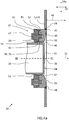
- figure 4a shows a sectional view of example embodiment of the cleaning nozzle 20 in a mounted stated in a wall 3-5 of a mixing tank 1.
- the tank cleaning nozzle 20 has a longitudinal direction 30, a first lateral direction 31a perpendicular to the longitudinal direction 30 and a second lateral direction 31b that is perpendicular to the longitudinal direction 30 and the first lateral direction 31a.
- the cleaning nozzle 20 is arranged for receiving pressurised cleaning fluid at an inlet port 57 from the cleaning fluid supply pipe 18, and to convey the cleaning fluid through the cleaning nozzle to an injection opening 36 for spraying cleaning fluid into the tank 1 for cleaning of the tank 1 and/or the agitator arrangement 2.
- the cleaning nozzle 20 comprises an attachment flange 32 having a through-hole 33 and configured for being attached to a wall 3-5 of a mixing tank 1, such that the longitudinal direction 30 of the tank cleaning nozzle 20 is oriented substantially normal to an interior surface 34 of the wall 3-5 of the mixing tank 1 at the location of the tank cleaning nozzle 20.
- FIG. 4a For clarity, a normal 48 to the interior surface 34 of the wall 3-5 of the mixing tank 1 at the location of the tank cleaning nozzle 20 is shown in figure 4a .
- the cleaning nozzle 20 further comprises a nozzle insert 35 arranged at the through-hole 33, wherein the nozzle insert 35 has an injection opening 36 configured for injecting a cleaning fluid into the mixing tank 1.
- the tank cleaning nozzle 20 further comprises a fastening arrangement 37 for fastening the nozzle insert 35 to the attachment flange 32, wherein the nozzle insert 35 is spherically moveably mounted relative to the attachment flange 32, for enabling adjustment of the injection direction 23 of the cleaning fluid.
- the fastening arrangement 37 is configured to fasten the nozzle insert 35 in a desired spherical position, for example be friction clamping of the nozzle insert 35 against the attachment flange 32.
- the attachment flange 32 is sealingly attached to the wall 3-5 of the mixing tank 1, for example by welding 45, soldering, or clamping by threaded members or rivets, or the like.
- the attachment flange 32 is typically circular and configured for being attached in a hole 44 in the wall of the mixing tank 1.
- the attachment flange 32 may according to certain embodiments have a seat 38, and the nozzle insert 35 may have an at least partly spherical exterior sliding surface 39 that is configured for being in sliding engagement with the seat 38 of the attachment flange 32.
- the seat 38 of the attachment flange 32 that is configured for being in sliding engagement with the spherical exterior sliding surface 39 of the nozzle insert 35, may have an at least partly spherical sliding surface that may correspond to the spherical exterior sliding surface of the nozzle insert 35.
- the seat 38 of the attachment flange 32 may have a conical sliding surface, or a curved funnel shaped surface, configured for being in sliding engagement with the spherical exterior sliding surface 39 of the nozzle insert 35.
- the seat 38 of the attachment flange 32 partly faces towards a rear side 40 of the tank cleaning nozzle 20.
- the spherical exterior sliding surface 39 of the nozzle insert 35 may be pressed against the seat 38 of the attachment flange 32 when a force pushes to nozzle insert toward a front side 41 of the nozzle insert 20.
- the rear side 40 of the cleaning nozzle refers to the side of the nozzle 20 facing away from the intended injection direction 23, i.e. facing toward an exterior of the mixing tank 1
- front side 41 of the cleaning nozzle 20 refers to the side of the nozzle 20 facing in same direction as the intended injection direction 23, i.e. towards an intended interior of the mixing tank 2.
- the fastening arrangement 37 is configured for exerting a clamping force on the nozzle insert 35 in the longitudinal direction 30 towards the front side 41 for urging the nozzle insert 35 against the seat 38 of the attachment flange 32.
- the fastening arrangement 38 may first, during an adjustment mode, be set in a loose mode or low contact pressure mode for enabling low friction force between the spherical exterior sliding surface 39 of the nozzle insert and the seat 38 of the attachment flange 32 enabling simply adjustment of the injection direction 23, and subsequently, when the nozzle insert has be set in a position providing a desired injection direction, the fastening arrangement 37 may be tightened to clamp the nozzle insert 35 against the seat 38 of the attachment flange 32 for ensuring rigid, robust and non-movable fastening of the nozzle insert 35.
- the fastening arrangement has a seat 42
- the nozzle insert 35 has a spherical exterior sliding surface 39 that is configured for being in sliding engagement with the seat 42 of the fastening arrangement 37.
- the spherical exterior sliding surface 39 of the nozzle insert 35 that is configured for sliding engagement with the seat 42 of the fastening arrangement 37 may be continuous with, i.e. switching smoothly and step-less to, the spherical exterior sliding surface 39 of the nozzle insert 35 that is configured for sliding engagement with the seat 38 of the attachment flange 32.
- the nozzle insert 35 may include a recess, groove, or step between the spherical exterior sliding surface 39 of the nozzle insert 35 that is configured for sliding engagement with the seat 42 of the fastening arrangement 37 and the spherical exterior sliding surface 39 of the nozzle insert 35 that is configured for sliding engagement with the seat 38 of the attachment flange 32.
- the seat 42 of the fastening arrangement 37 which is configured for being in sliding engagement with the spherical exterior sliding surface 39 of the nozzle insert 35, has an at least partly spherical sliding surface corresponding to the spherical exterior sliding surface 39 of the nozzle insert 35.
- the seat 42 of the fastening arrangement 37 that is configured for being in sliding engagement with the spherical exterior sliding surface 39 of the nozzle insert 35 may have an at least partly conical sliding surface, or a curved funnel shaped surface.
- the fastening arrangement 37 for fastening the spherically mounted nozzle insert 35 may comprises plurality of circular segments 43, such as two circular segments 43, configured for exerting a clamping force on the nozzle insert 35 in the longitudinal direction 30.
- the fastening arrangement 37 may comprises a ring for engaging and pressing the nozzle insert 35 in the longitudinal direction 30.
- a fastening arrangement 37 in form of circular segments 43 may enable simplified installation and mounting of the fastening arrangement, because the segments 43 may be installed without free access to rear end of the nozzle insert 35, as a ring-shaped fastening arrangement 37 typically requires.
- the tank cleaning nozzle 20 may for example include threaded fasteners 47, e.g. in the form of bolts, configured for being threadingly received in holes 53 on a rear side 40 of the attachment flange 32 and for pressing the fastening arrangement 37 towards the attachment flange 32.
- threaded fasteners 47 e.g. in the form of bolts
- Sealing of the cleaning nozzle 20 for avoiding leakage of a mixing product within the tank 1 is generally desired.
- the connection between the stationary attachment flange 32 and the wall 3-5 of the tank 1 is sealed by welding, soldering, clamping or the like, possibly by means also of one or more sealing rings at appropriate locations.
- a sealed connection between the spherically moveably mounted nozzle insert 35 and attachment flange 32 may for example be accomplished by providing the attachment flange 32 with a sealing device 46 arranged at the seat 38 of the attachment flange 32 and configured for sealing engagement with the spherical exterior sliding surface 39 of the nozzle insert 35. Thereby, spherical motion of the injection nozzle for adjustment of injection direction 23 may be performed without leakage.
- the sealing device 46 may for example by an O-ring or the like.
- the sealed connection between the spherically moveably mounted nozzle insert 35 and attachment flange 32 may alternatively be accomplished by providing the nozzle insert with the sealing device arranged at the spherical exterior sliding surface 39 of the nozzle insert 35 and configured for sealing engagement with the seat 38 of the attachment flange 32.
- the seat 38 associated with the attachment flange 32 and/or the spherical exterior sliding surface 39 associated with the nozzle insert 35 may in fact be provided on an additional intermediate component, and in such case, the sealed connection between the spherically moveably mounted nozzle insert 35 and attachment flange 32 may alternatively be accomplished by providing one or both of said intermediate components with the sealing device arranged at the spherical exterior sliding surface and/or seat.
- the sealing device 46 itself may provide the spherical exterior sliding surface 39 of the nozzle insert 35.
- the nozzle insert 35 may have for example a cylindrical exterior surface at a front end thereof, and a sealing device 46 with a spherical exterior sliding surface 39 being secured on the cylindrical end portion of the nozzle insert 35, wherein the spherical exterior sliding surface 39 of the sealing device 46 is arranged for sliding and sealing contact with the seat 38 of the attachment flange 32.
- the sealed connection may be provided between the spherically moveably mounted nozzle insert 35 and the fastening arrangement 37 instead.
- the attachment flange 32 may have a substantially planar front surface 49, and the attachment flange 32 may be configured to be mounted in the wall 3-5 of the mixing tank 1 such that the planar front surface 49 is substantially flush with a neighbouring interior surface 34 of the wall 3-5 of the mixing tank 1.Thereby, cleaning of the area of the cleaning nozzle 20 exposed to the interior of the mixing tank 1 is simplified, and the space for contaminants is reduced.
- the nozzle insert 35 may have a substantially planar circular front surface 51 facing the front side 41 and arranged next to the spherical exterior sliding surface 39 of the nozzle insert 35.
- the recess 52 formed between the attachment flange 32 and nozzle insert 35 is kept shallow, and the nozzle insert 35 may be located relatively close to the substantially planar front surface 49 of the attachment flange 32 for reducing space for containments, but without protruding beyond the interior surface 34 of the wall 3-5 of the mixing tank for enabling use of impeller that swipes along the interior surface 34 of the wall 3-5.
- a distance 54 in the longitudinal direction 30 between a first plane defined by an annular most forward surface 55 of the attachment flange 32 and a second plane defined by a most forward and substantially planar circular front surface 51 of the nozzle insert 35 is in the range of 1 - 10 mm, specifically 2 - 5 mm, when the first and second planes are parallel, as illustrated in figure 4a .
- attachment flange 32 may have a sloping surface 56 adjacent the through-hole 33 for providing a smooth and continuous transition between the substantially planar front surface 55 and the seat 38 of the attachment flange 35.
- cleaning of the cleaning nozzle 20 is simplified, and contaminants may less easily remain in corner areas.
- Figure 4b and 4c show the cleaning nozzle 20 of figure 4a in two different adjustment positions, having two different injection directions 23.
- the injection direction 23 defines an angle 24 of about 5° in a first direction with respect to a central injection direction 25 of the nozzle 20
- the injection direction 23 defines an angle 24 of about 5° in a second direction, opposite to the first direction, with respect to a central injection direction 25 of the nozzle 20.
- the tank cleaning nozzle 20 may comprise a motion limiting arrangement preventing the nozzle insert 35 from being adjusted such that any portion of the nozzle insert 35 extends beyond a plane defined by an annular most forward surface 55 of the attachment flange 32, in the longitudinal direction 30 towards the front side 41.
- the motion limiting arrangement, i.e. adjustment stop, of the nozzle insert 35 may be provided.
- the motion limiting arrangement comprises a blocking surface 60 of the fastening arrangement 37 that cooperates with a corresponding blocking surface 74 on the nozzle insert 35.
- the motion limiting arrangement is composed of a blocking surface 60 on each of the two circular segments 43 of the fastening arrangement 37 that cooperates with a corresponding blocking surface 74 on the nozzle insert 35.
- the corresponding blocking surface 74 may for example correspond to an exterior side surface of the nozzle insert 35 located side by side with the spherical exterior sliding surface 39 of the nozzle insert 35.
- the motion limiting arrangement comprises an blocking surface 60 located on the fastening arrangement 37 and configured for engaging with the nozzle insert 35 for preventing the nozzle insert 35 from being adjusted such that any portion of the nozzle insert 35 extends beyond a plane defined by an annular most forward surface 55 of the attachment flange 32, in the longitudinal direction 30 towards the front side 41.
- Figure 4d shows an exploded view of the cleaning nozzle 20 of figures 4a-4c , showing for example an annular groove 61 provided in the attachment flange 32 in the area of the through-hole 33 and configured for receiving the sealing device 46.
- a diameter 62 of the spherical exterior sliding surface 39 and a diameter 63 of the substantially planar circular front surface of the nozzle insert 35 is also identified, wherein the diameter 63 of the substantially planar circular front surface of the nozzle insert 35 is in the range of 70 - 98%, specifically 80 - 96%, and more specifically 90 - 95%, of the exterior diameter 62 of the spherical exterior sliding surface 39 of the nozzle insert 35.
- the nozzle insert 35 may be located relatively close to the front end of the cleaning nozzle for keeping the recess formed in the interior wall of the tank at the location of the cleaning nozzle relatively small and shallow, while still avoiding that the nozzle insert protrudes beyond the plane defined by the annular most forward surface 55 of the attachment flange 32, and/or beyond the interior surface 34 of the wall 3-5 of the mixing tank.
- a small and shallow recess is generally desirable for enabling improved cleaning of the area of the cleaning nozzle and avoiding having the nozzle insert protruding beyond the interior surface 34 of the wall 3-5 of the mixing tank is generally desirable for avoiding any risk for interference with the agitator arrangement.
- figure 4d also clearly shows that the fastening arrangement 37 and attachment flange 32 have a positioning mechanism for controlling the mutual relative position.
- a positioning mechanism is provided that assists with placing the fastening arrangement 37 and attachment flange 32 in a correct position relative to each other upon fastening of the fastening arrangement 37 to the attachment flange 32.
- the correct relative position of the fastening arrangement 37, such as multiple circular segments 43 or a ring, to the attachment flange 32 is important for providing a good distribution of clamping force by the seat 42 of the fastening arrangement 37 against the spherical exterior sliding surface 39 of the nozzle insert 35, and thus a reliable fastening of the adjustable nozzle insert in a desired angular position.
- the correct relative position of the fastening arrangement 37 to the attachment flange 32 is important when the motion limiting arrangement includes the blocking surface 60 of the fastening arrangement 37 as described above, because this requires correct positioning of the fastening arrangement 37 relative to the nozzle insert 35 for accomplishing correct motion limiting performance.
- the positioning mechanism comprises a protrusion 64 in the attachment flange 32 and a corresponding recess on the fastening arrangement 37.
- the recess 65 is configured to fit with high accuracy within the protrusion 64 of the attachment flange 32, such that correct relative position between the attachment flange 32 and the fastening arrangement 37 can be easily and automatically accomplished upon assembly of said parts.
- the positioning mechanism could be arranged oppositely, i.e. having the recess in the fastening arrangement and the corresponding protrusion in the attachment flange.
- the protrusion 64 and corresponding recess 65 of the positioning mechanism can have tapered side surfaces 66, as seen in the longitudinal direction 30 of the cleaning nozzle 20, for enabling further improved automatic mutual positioning
- a diameter 67 of through-holes 68 of the fastening arrangement 37 may be significantly larger than the diameter 69 of the threaded fasteners 47, such that a relatively large play between threaded fasteners 47 and through-holes 68 is accomplished, thus simplifying insertion and screwing of threaded fasteners 47 into the holes 53 on a rear side 40 of the attachment flange 32, but without negatively effecting the correct positioning of the fastening arrangement 37 relative to the attachment flange 32.
- the example embodiments of the cleaning nozzle 20 described above with reference to figures 3a - 6 have been spherically moveably mounted relative to the attachment flange 32 for enabling adjustment of the injection direction 23 of the cleaning fluid. This is advantageous because it allows large flexibility in terms of adjustment, namely in both the first and second lateral directions 31a, 31b, of the cleaning nozzle 20. However, in certain applications, it may be sufficient or desirable to have a cleaning nozzle 20 that is adjustable in one lateral direction only, or it may be desirable to provide a less complex design of the cleaning nozzle. An example embodiment of a tank cleaning nozzle with a pivotally adjustable nozzle insert is therefore described below with reference to figures 7a-8d .
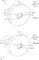
- Figure 7a and 7b shows 3D views of the cleaning nozzle from mainly a rear side 40 with the nozzle insert 35 in two different angular positions
- figures 7c and 7d shows 3D views of the cleaning nozzle from mainly the front side 41 with the nozzle insert 35 in said two different angular positions
- figure 8a shows a side view of the cleaning nozzle from a direction perpendicular to the pivot axis
- figure 8b shows section B-B of figure 8a
- figure 8c shows a side view of the cleaning nozzle from a direction parallel with the pivot axis
- figure 8d shows section A-A of figure 8c .
- the tank cleaning nozzle 20 has a longitudinal direction 30, a first lateral direction 31a perpendicular to the longitudinal direction 30 and a second lateral direction 31b that is perpendicular to the longitudinal direction 30 and the first lateral direction 31a.
- the cleaning nozzle 20 comprises an attachment flange 32 having a through-hole 33 and configured for being attached to a wall 3-5 of a mixing tank 1, such that the longitudinal direction 30 of the tank cleaning nozzle 20 is oriented substantially normal to an interior surface 34 of the wall 3-5 of the mixing tank 1 at the location of the tank cleaning nozzle 20.
- the cleaning nozzle 20 further comprises a nozzle insert 35 arranged at the through-hole 33, wherein the nozzle insert 35 has an injection opening 36 configured for injecting a cleaning fluid into the mixing tank 1.
- the tank cleaning nozzle 20 further comprises a fastening arrangement 37 for fastening the nozzle insert 35 to the attachment flange 32, wherein the nozzle insert 35 is pivotably moveably mounted relative to the attachment flange 32 about an axis oriented in parallel with the first lateral direction 31a, for enabling adjustment of the injection direction 23 of the cleaning fluid.
- the nozzle insert 35 is capable of performing pivotal motion relative to the attachment flange 32 about said axis.
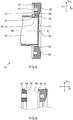
- the nozzle insert 35 has an at least partly cylindrical exterior sliding surface 70 that is configured for being in sliding engagement with the seat 38 of the attachment flange 32.
- the seat 38 of the attachment flange 32 which is configured for being in sliding engagement with the cylindrical exterior sliding surface 70 of the nozzle insert 35, may for example have an at least partly cylindrical sliding surface corresponding to the cylindrical exterior sliding surface 70 of the nozzle insert 35.
- seat 38 of the attachment flange 32 may be composed of a planar surface, thus giving raise to point or line contact with the cylindrical exterior sliding surface 70 of the nozzle insert 35.
- the through-hole 33 in the attachment flange may be circular or of another shape and is preferably arranged to overlap with an area of the injection opening 36 of the nozzle insert 35, such that cleaning fluid may be sprayed from the injection opening 36, through the through-hole, and further into the tank 1 for cleaning of the tank 1 and/or the agitator arrangement 2.
- the nozzle insert 35 may be clamped and pressed against the seat 38 of the attachment flange 32 by means of the fastening arrangement 37.
- the fastening arrangement 37 for fastening the pivotally mounted nozzle insert 35 may comprise one, two or more brackets 71 configured for exerting a clamping force on the nozzle insert 35 in the longitudinal direction 30.
- the fastening arrangement 37 may include one bracket 71 on each side of the nozzle insert 35.
- the nozzle insert 35 may for example include two shaft portions 72 that protrude on each side of the nozzle insert 35 coaxial with the cylindrical exterior sliding surface 70 of the nozzle insert 35, and the brackets 71 may be arranged to engage with said shaft portions 72.
- the tank cleaning nozzle may for example include threaded fasteners 47, e.g. in the form of bolts, configured for being threadingly received in holes on a rear side of the attachment flange 32 and for pressing the fastening arrangement, in particular the brackets 71, towards the attachment flange 32.
- threaded fasteners 47 e.g. in the form of bolts, configured for being threadingly received in holes on a rear side of the attachment flange 32 and for pressing the fastening arrangement, in particular the brackets 71, towards the attachment flange 32.
- the fastening arrangement in particular the brackets 71, may each have a seat 42, and wherein each of the shaft portions 72 has a cylindrical exterior sliding surface 73 that is configured for being in sliding engagement with the seat 42 of the fastening arrangement 37.
- the attachment flange 32 may further have a sealing device 46 arranged at the seat 38 of the attachment flange 32 and configured for sealing engagement with the cylindrical exterior sliding surface 70 of the nozzle insert 35, as shown in figure 8b .
- the nozzle insert 35 may have a sealing device arranged at the cylindrical exterior sliding surface 70 of the nozzle insert 35 and configured for sealing engagement with the seat 38 of the attachment flange 32.
- both the spherically and pivotally adjustable version of the cleaning nozzle 20 may be provided with a valve member for controlling a flow of cleaning fluid from a cleaning fluid inlet 57 to the injection opening 36 of the nozzle insert 35.
- a valve member for controlling a flow of cleaning fluid from a cleaning fluid inlet 57 to the injection opening 36 of the nozzle insert 35.
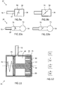
- figure 9a and 9b show a spherically adjustable version of the cleaning nozzle 20 having a valve member 75 in a closed and open state, respectively
- figure 10a and 10b show a pivotally adjustable version of the cleaning nozzle 20 having a valve member 75 in a closed and open state, respectively.
- valve member 75 may be accomplished by hand by a user, or by means of a pneumatic, electric, hydraulic actuator (not showed) or the like that is controlled by an electronic controller. Alternatively, the valve member 75 may be arranged to open automatically upon supply of pressurised cleaning fluid to the cleaning nozzle 20, as illustrated in figure 11 .
- the example embodiment of the nozzle insert 35 of figure 11 comprises an internal spring-loaded valve member 75, wherein the spring 76 exerts a force on the valve member towards the closed state, in which an annular seal 77 closes the flow passage through the cleaning nozzle 20.
- cleaning fluid may enter and pass through passages 59 of a front plate 78 of the valve member 75 and exert a pressure urging the valve member 75 rearwards against the force of the spring 76, such that a flow passage automatically opens from the inlet port 57 to the injection opening 36 for spraying cleaning fluid into the tank 1 for cleaning of the tank 1 and/or the agitator arrangement 2.
- the valve member 75 will automatically return to closed state.
- a valve member may be provided in the cleaning fluid supply pipe 18, or somewhere else upstream of the cleaning nozzle 20, for controlling the injection of cleaning fluid into the tank 1.
- the disclosure also relates to a method for mounting a tank cleaning nozzle 20 in a wall 3-5 of a mixing tank 1.
- the method comprises a first step S1 of attaching an attachment flange 32 having a through-hole 33 to a wall 3-5 of the mixing tank1, wherein the longitudinal direction 30 of the tank cleaning nozzle 20 is oriented substantially normal to an interior surface of the wall 3-5 of the mixing tank 1 at the location of the tank cleaning nozzle 20.
- the method further comprises a second step S2 of arranging a nozzle insert 35 at the through-hole 33, such that an injection opening 36 of the nozzle insert 35 is configured for injecting the cleaning fluid into the mixing tank 1.
- the method comprises a third step S3 of fastening the nozzle insert 35 to the attachment flange 32 using a fastening arrangement 37. Thereafter, before final clamping of the nozzle insert 35, the method may comprise a fourth step S4 of adjusting an injection direction 23 of the cleaning fluid by spherical motion of the nozzle insert 35 relative to the attachment flange 32, and/or pivotal motion of the nozzle insert 35 relative to the attachment flange 32 about an axis oriented in parallel with the first lateral direction 31a.
- the method thus typically also includes a fifth step of clamping the nozzle insert 35 for securing the angular or spherical position of the nozzle insert 35 after adjustment. Consequently, after the third step S3 of fastening the nozzle insert 35 to the attachment flange 32 using the fastening arrangement 37, and before the fifth step of clamping the nozzle insert 35, the nozzle insert 35 is typically only fastened with a small, or zero, clamping torque, such that adjustment of the injection direction 23 can still be performed.
Landscapes
- Chemical & Material Sciences (AREA)
- Chemical Kinetics & Catalysis (AREA)
- Engineering & Computer Science (AREA)
- Mechanical Engineering (AREA)
- Cleaning In General (AREA)
- Cleaning By Liquid Or Steam (AREA)
Abstract
A tank cleaning nozzle (20) having a longitudinal direction (30), a first lateral direction (31a) perpendicular to the longitudinal direction (30). The tank cleaning nozzle comprises an attachment flange (32) having a through-hole (33) and configured for being attached to a wall (3-5) of a mixing tank (1), such that the longitudinal direction (30) of the tank cleaning nozzle (20) is oriented substantially normal to an interior surface (34) of the wall (3-5) of the mixing tank (1) at the location of the tank cleaning nozzle (20), and a nozzle insert (35) arranged at the through-hole (33) and having an injection opening (36) configured for injecting a cleaning fluid into the mixing tank. The tank cleaning nozzle (20) further comprises a fastening arrangement (37) for fastening the nozzle insert (35) to the attachment flange (32), and wherein the nozzle insert (35) is spherically moveably mounted relative to the attachment flange (32), and/or pivotably moveably mounted relative to the attachment flange (32) about an axis oriented in parallel with the first lateral direction (31a), for enabling adjustment of an injection direction (23) of the cleaning fluid. The disclosure also concerns a method for mounting a tank cleaning nozzle (20) in a wall (3-5) of a mixing tank (1).
Description
- The present disclosure relates to a tank cleaning nozzle. The disclosure further relates to a method for mounting a tank cleaning nozzle in a wall of a mixing tank.
- The tank cleaning nozzle according to the disclosure is specifically arranged for being mounted in a mixing tank having an agitator arrangement for mixing a product, in particular a liquid product, such as for example a food product, a pharmaceutical product, a cosmetic product, or the like.
- In various industries making use of mixing tanks and agitators for preparing a liquid product, such as the food and beverage industry or pharmaceutical industry, there is a need for mixing tanks providing highly efficient mixing, improved cost-efficiency, zero in-tank maintenance and low risk for contamination of the product.
- Efficient and thorough cleaning of the interior of the mixing tank between consecutive batches is an important step for reducing the risk for contamination of the product. One solution for cleaning of the interior of the mixing tank is shown in document
EP0310185 A1 , which shows a spraying head for cleaning the interior of the kettle by spraying a cleaning medium. - However, despite the activities in the field, currently known solutions are not entirely satisfactory. There is therefore still a demand for an improved tank cleaning nozzle, which is providing further improved cleaning and cost-efficient installation.
- In certain applications, the positioning and orientation of the tank cleaning nozzle is of particular importance. For example, in certain applications, the orientation and direction of the spray of cleaning fluid exiting the tank cleaning nozzle may have to be carefully selected and adjusted depending on the location of the agitator arrangement within the tank. However, considering that the orientation and direction of said cleaning fluid generally depends at least partly on the relative positioning of the cleaning nozzle within the wall of the tank, the installation effort of tank cleaning nozzles within the wall of mixing tanks is high.
- Consequently, an object of the present disclosure is to provide a tank cleaning nozzle, and method for mounting a tank cleaning nozzle in a wall of a mixing tank, where the previously mentioned problems are avoided, in particular with respect to further improved cleaning and cost-efficient nozzle installation.
- This object is at least partly achieved by the features of the independent claims.
- According to a first aspect of the present disclosure, there is provided a tank cleaning nozzle having a longitudinal direction, a first lateral direction perpendicular to the longitudinal direction. The tank cleaning nozzle comprises an attachment flange having a through-hole and being configured for being attached to a wall of a mixing tank, such that the longitudinal direction of the tank cleaning nozzle is oriented substantially normal to an interior surface of the wall of the mixing tank at the location of the tank cleaning nozzle. The tank cleaning nozzle further comprises a nozzle insert arranged at the through-hole and having an injection opening configured for injecting a cleaning fluid into the mixing tank, and a fastening arrangement for fastening the nozzle insert to the attachment flange, wherein the nozzle insert is spherically moveably mounted relative to the attachment flange, and/or pivotably moveably mounted relative to the attachment flange about an axis oriented in parallel with the first lateral direction, for enabling adjustment of an injection direction of the cleaning fluid.
- According to a second aspect of the present disclosure, there is provided a method for mounting a tank cleaning nozzle in a wall of a mixing tank, wherein the tank cleaning nozzle has a longitudinal direction and a first lateral direction perpendicular to the longitudinal direction. The method comprises attaching an attachment flange having a through-hole to a wall of the mixing tank, wherein the longitudinal direction of the tank cleaning nozzle is oriented substantially normal to an interior surface of the wall of the mixing tank at the location of the tank cleaning nozzle. The method further comprises arranging a nozzle insert at the through-hole, such that an injection opening of the nozzle insert is configured for injecting a cleaning fluid into the mixing tank, fastening the nozzle insert to the attachment flange using a fastening arrangement, and adjusting an injection direction of the cleaning fluid by spherical motion of the nozzle insert relative to the attachment flange, and/or by pivotal motion of the nozzle insert relative to the attachment flange about an axis oriented in parallel with the first lateral direction.
- Since the tank cleaning nozzle according to the present disclosure enables simply and fast adjustment of the injection direction of the cleaning fluid, within the adjustment range of the cleaning nozzle, the installation effort for having the cleaning nozzle correctly attached to the wall of the mixing tank is significantly reduced.
- This comes from the fact that, in implementations where the direction and orientation of the spray is particularly relevant for the overall cleaning efficiency of the mixing tank and its agitator arrangement, the installation of prior art cleaning nozzles within the wall of the mixing tank must be performed with care, because the direction and orientation of the spray from the cleaning nozzle is typically non-adjustable and thus directly dependent on the fastening position of the attachment flange to the wall of the mixing tank. In other words, fastening of the attachment flange, for example be welding, to the wall of the mixing tank is a difficult and time consuming task.
- However, the tank cleaning nozzle according to the disclosure enables simplified installation of the cleaning nozzle because the exact position of the attachment flange relative to the wall of the mixing tank is no longer essential for accomplishing the desired spray direction. Consequently, the cleaning nozzle according to the disclosure enables a more cost-efficient installation of the cleaning nozzle, as well as improved cleaning, because the spray direction of the cleaning nozzle can be easily adjusted for obtaining a final spray direction that provides efficient cleaning of the mixing tank and/or agitator arrangement.
- Further advantages are achieved by implementing one or several of the features of the dependent claims.
- In some example embodiments, the attachment flange has a seat and the nozzle insert has an at least partly spherical or an at least partly cylindrical exterior sliding surface that is configured for being in sliding engagement with the seat of the attachment flange. When the nozzle insert has an at least partly spherical exterior sliding surface in sliding engagement with the seat of the attachment flange, a spherical motion of the nozzle insert relative to the attachment flange is made possible, for enabling a high degree of adjustment of the nozzle insert, and thus a high degree of adjustment of the spray direction. Alternatively, when the nozzle insert has an at least partly cylindrical sliding surface that is in sliding engagement with the seat of the attachment flange, a pivotal motion of the nozzle insert relative to the attachment flange around a pivot axis is made possible, for enabling pivotal adjustment of the nozzle insert, and thus pivotal adjustment of a spray direction.
- In some example embodiments, the tank cleaning nozzle has a front side configured for facing toward an interior of the mixing tank and a rear side configured for facing toward an exterior of the mixing tank, and wherein the fastening arrangement is configured for exerting a clamping force on the nozzle insert in the longitudinal direction towards the front side for urging the nozzle insert against the seat of the attachment flange. Thereby, a robust connection is accomplished that enables longitudinal compression of a sealing device for ensuring high sealing performance. In addition, the angular position of the nozzle insert may be easily adjusted when the fastening arrangement initially is set to provide a small clamping force, and subsequently firmly tightened to ensure stable fastening of the nozzle insert in the selected angular position.
- In some example embodiments, the seat of the attachment flange partly faces towards a rear side of the tank cleaning nozzle. Thereby, the clamping force supplied by fastening arrangement in the longitudinal direction towards the front side can be transferred from the nozzle insert to the seat of attachment flange.
- In some example embodiments, the fastening arrangement for fastening the spherically mounted nozzle insert comprises a ring or a plurality of circular segments configured for exerting a clamping force on the nozzle insert in the longitudinal direction, or the fastening arrangement for fastening the pivotally mounted nozzle insert comprises one, two or more brackets configured for exerting a clamping force on the nozzle insert in the longitudinal direction, specifically one bracket on each side of the nozzle insert. This provides a strong, cost-efficient and user-friendly design of the fastening arrangement.
- In some example embodiments, the attachment flange has a sealing device arranged at the seat of the attachment flange and configured for sealing engagement with the cylindrical or spherical exterior sliding surface of the nozzle insert, or the nozzle insert has a sealing device arranged at the cylindrical or spherical exterior sliding surface of the nozzle insert and configured for sealing engagement with the seat of the attachment flange. Thereby, a sealed but still adjustable connection is provided.
- In some example embodiments, the seat of the attachment flange, which is configured for being in sliding engagement with the cylindrical or spherical exterior sliding surface of the nozzle insert, has at least partly a cylindrical or spherical sliding surface corresponding to, or not corresponding to, the cylindrical or spherical exterior sliding surface of the nozzle insert, or a conical sliding surface, or a curved funnel shaped surface. Hence, depending on the circumstances, the surface design of the seat may selected for each specific implementation.
- In some example embodiments, the fastening arrangement has a seat, and the nozzle insert has a cylindrical or spherical exterior sliding surface that is configured for being in sliding engagement with the seat of the fastening arrangement. Thereby, the clamping force from the fastening arrangement may be properly transferred to the nozzle insert.
- In some example embodiments, the seat of the fastening arrangement, which is configured for being in sliding engagement with the cylindrical or spherical exterior sliding surface of the nozzle insert, has at least partly a cylindrical or spherical sliding surface corresponding to, or not corresponding to, the cylindrical or spherical exterior sliding surface of the nozzle insert, or a conical sliding surface, or a curved funnel shaped surface.
- In some example embodiments, the fastening arrangement and attachment flange have a positioning mechanism for controlling the mutual relative position. Thereby, the installation and mounting of the cleaning nozzle is simplified.
- In some example embodiments, the positioning mechanism comprises a recess in one of the fastening arrangement and attachment flange, and a corresponding protrusion on the other of the fastening arrangement and attachment flange.
- In some example embodiments, the tank cleaning nozzle comprises threaded fasteners configured for being threadingly received in holes on a rear side of the attachment flange and for pressing the fastening arrangement towards the attachment flange. This solution provides a cost-efficient and user-friendly fastening arrangement.
- In some example embodiments, wherein the tank cleaning nozzle comprises a motion limiting arrangement preventing the nozzle insert from being adjusted such that any portion of the nozzle insert extends beyond a plane defined by an annular most forward surface of the attachment flange, in the longitudinal direction towards the front side. Thereby, undesired interference between the cleaning nozzle and the agitator arrangement can be avoided.
- In some example embodiments, the motion limiting arrangement comprises an blocking surface located on the fastening arrangement and configured for engaging with the nozzle insert for preventing the nozzle insert from being adjusted such that any portion of the nozzle insert extends beyond a plane defined by an annular most forward surface of the attachment flange, in the longitudinal direction towards the front side. Thereby, existing parts of the cleaning nozzle may be used for motion limiting arrangement for ensuring cost-efficient overall design.
- In some example embodiments, the attachment flange has a substantially planarfront surface, and wherein the attachment flange is configured to be mounted in the wall of the mixing tank such that the planar front surface is substantially flush with a neighbouring interior wall of the mixing tank. Thereby, the risk for contaminants at the cleaning nozzle is reduced.
- In some example embodiments, the nozzle insert has a substantially planar circular front surface arranged next to the spherical exterior sliding surface of the nozzle insert. Thereby, the cavity formed by the nozzle insert may be kept small for simplified cleaning of the mixing tank in the area of the cleaning nozzle.
- In some example embodiments, a diameter of the substantially planar circular front surface is in the range of 70 - 98%, specifically 80 - 96%, and more specifically 90 - 95%, of an exterior diameter of the spherical exterior sliding surface of the nozzle insert. Thereby, the size of the recess at the cleaning nozzle may be small.
- In some example embodiments, a distance in the longitudinal direction between a first plane defined by an annular most forward surface of the attachment flange and a second plane defined by a most forward and substantially planar circular front surface of the nozzle insert is in the range of 1 - 10 mm, specifically 2 - 5 mm, when the first and second planes are parallel. Thereby, the size of the recess at the cleaning nozzle may be small.
- In some example embodiments, the attachment flange has a sloping surface adjacent the through-hole for providing a smooth and continuous transition between the substantially planar front surface and the seat of the attachment flange. Thereby, the risk for contaminants, pollutants, dirt or soil in the area of the cleaning nozzle in reduced.
- In some example embodiments, the tank cleaning nozzle comprises a valve member for controlling a flow of cleaning fluid from a cleaning fluid inlet to the injection opening of the nozzle insert.
- Mixing tank comprising a tank cleaning nozzle as described above mounted in a wall of the mixing tank and configured for injecting a cleaning fluid into the mixing tank.
- In some example embodiments, the mixing tank further comprising an agitator arrangement having a rotatable shaft and an impeller secured to the shaft, and the tank cleaning nozzle is mounted in a side wall or bottom wall of the mixing tank and configured for injecting a cleaning fluid on the impeller.
- Further features and advantages of the invention will become apparent when studying the appended claims and the following description. The skilled person in the art realizes that different features of the present disclosure may be combined to create embodiments other than those explicitly described hereinabove and below, without departing from the scope of the present disclosure.
- The disclosure will be described in detail in the following, with reference to the attached drawings, in which
- Fig. 1
- shows schematically a side view if a mixing tank having a cleaning nozzle,
- Fig. 2a
- shows schematically a cross-section of the mixing tank of
figure 1 , as seen from above, - Fig. 2b
- shows schematically an example spray pattern,
- Fig. 3a
- shows a 3D view of an example embodiment of an adjustable cleaning nozzle,
- Fig. 3b
- shows a further 3D view of the cleaning nozzle of
figure 3a , - Fig. 3c
- shows an example embodiment of the fastening arrangement,
- Fig. 4a-4c
- show schematically cross-sections of a further example embodiment of an adjustable cleaning nozzle,
- Fig. 4d
- shows an exploded view of the cleaning nozzle of
figures 4a-4c , - Fig. 5
- shows schematically a further example embodiment of the adjustable cleaning nozzle,
- Fig. 6
- shows schematically a further example embodiment of the positioning mechanism,
- Fig. 7a-7d
- show schematically 3D views of a further example embodiment of the cleaning nozzle,
- Fig. 8a-8d
- show schematically side views and sectional views of the cleaning nozzle of
figures 7a-7d , - Fig. 9a-9b
- show schematically an example embodiment of a spherically adjustable nozzle insert having a valve member in closed and open state,
- Fig. 10a-10b
- show schematically an example embodiment of a pivotally adjustable nozzle insert having a valve member in closed and open state,
- Fig. 11
- shows schematically an example embodiment of an adjustable nozzle insert having an automatically operating valve member,
- Fig. 12
- shows schematically the main steps of a method according to the disclosure.
- Various aspects of the disclosure will hereinafter be described in conjunction with the appended drawings to illustrate and not to limit the disclosure, wherein like designations denote like elements, and variations of the described aspects are not restricted to the specifically shown embodiments, but are applicable on other variations of the disclosure.
-
Figure 1 schematically shows amixing tank 1 comprising anagitator arrangement 2 having arotatable shaft 6 and animpeller 7 secured to theshaft 6, wherein atank cleaning nozzle 20 is mounted in aside wall 5 orbottom wall 4 ortop wall 3 of themixing tank 1 and configured for injecting a cleaning fluid on theimpeller 7. - The
agitator arrangement 2 is installed within the tank for enabling mixing of a product, such as a liquid, within thetank 1. The mixing tank extends in avertical direction 10, a firsttransverse direction 11a, and a secondtransverse direction 11b that is perpendicular to thevertical direction 10 and the firsttransverse direction 11a. - The
agitator arrangement 2 may for example be attached to, and extend through, thetop wall 3 of thetank 1, as shown infigure 1 , but theagitator arrangement 2 may alternatively be attached to, and extend through, another wall, such that thebottom wall 4 orside wall 5 of thetank 1. - The height of the
tank 1 in thevertical direction 10 may for example be in the range of 1 - 10 metres, and the width of thetank 1 in the first and secondtransverse directions - The
impeller 7 corresponds to amixing tool 7, such as mixing blades or the like, secured to therotatable shaft 6 that is powered by amotor 8, for example via atransmission 9. Operation of themotor 8 will then cause the mixing tool to rotate within themixing tank 1 for mixing of a product within thetank 1. - The product may for example be filled into the
tank 1 via an inlet pipe 12 and emptied from thetank 1 via anoutlet pipe 13. - In the example embodiment of the
mixing tank 1 offigure 1 , a cleaningnozzle 20 is mounted within thesidewall 5 of thetank 1. The cleaningnozzle 20 is arranged for spraying a cleaningfluid 21 into thetank 1 for cleaning of thetank 1 and/or theagitator arrangement 2, for example between consecutive product batches. The cleaning fluid may be supplied to the cleaningnozzle 20 via a cleaningfluid supply pipe 18. - In the example embodiment of
figures 1 and2a , the cleaningnozzle 20 is mounted and configured to have an injection direction of cleaningfluid 21 primarily in the firsttransverse direction 11a, even if the cleaningnozzle 20 typically is configured to generate a spray of cleaningfluid 21 having a certain spray pattern, such as flat pattern, round pattern, or the like. The term "injection direction" thus herein refers to a central main direction of a certain spray pattern of the cleaningnozzle 20. -
Figure 2a schematically illustrates a cross-sectional view of thetank 1 at section C-C offigure 1 . The cleaningnozzle 20 includes an adjustment mechanism for enabling adjustment of the injection direction of the cleaning fluid relative to thetank 1 andagitator arrangement 2 when being mounted in thesidewall 5 of thetank 1. This adjustment of the injection direction of the cleaningfluid 21 is illustrated infigure 2a in form ofangular range 22 defining the maximal adjustment range of the cleaningnozzle 20. In other words, the cleaningnozzle 20 can be adjusted by means of the adjustment mechanism of the cleaning nozzle for having a direction injection anywhere within theangular range 22. - As described more in detail below, the
angular range 22 may extend only in a single plane, as provided when the cleaningnozzle 22 is adjustable around only a single pivot axis. Alternatively, theangular range 22 may extend in two mutually perpendicular planes, as provided when the cleaningnozzle 22 is adjustable around two perpendicular pivot axes, or as provided by a sphericallyadjustable cleaning nozzle 20. The single plane or two mutually perpendicular planes may, depending on the mounting position of the cleaning nozzle, be aligned with a vertical and/or horizontal plane, or be inclined with respect to the vertical and/or horizontal planes. - The injection direction, as illustrated by
arrow 23 infigure 2a , may for example be adjustable over anangular range 22 of 3 - 90°, specifically 7 - 50°, and more specifically 10 - 25°. This applies to each plane, in which the cleaning nozzle in adjustable, and theadjustment range 22 may be the same or different in each plane. - In the example installation of the cleaning
nozzle 20 intank 1 offigure 2a , theinjection direction 23 defines anangle 24 of about 5° with respect to acentral injection direction 25 of thenozzle 20. -
Figure 2b schematically illustrates oneexample spray pattern 26 of the cleaningnozzle 20, which spraypattern 26 may be referred to as flat spray pattern because of its elongated elliptical shape in thevertical direction 10. Thisspray pattern 26 may be advantageously used for cleaning of theagitator arrangement 2, because it covers a relatively large scope in thevertical direction 10, but can maintain a relatively strong injection force by keeping the spray pattern narrow, i.e. focused, in the secondtransverse direction 11b. For example, the spray angle in the vertical direction may be in the range of 15 - 60°, and the spray angle in the second transverse direction may be in the range of 10 - 50% of the spray angle in the vertical direction. - Other types of spray patterns are for example solid stream, full cone, hollow cone, spoon flat fan, straight, etc.
- The
injection direction 23 of the cleaning nozzle may have large impact on the overall cleaning efficiency of the cleaningnozzle 20, especially when the spray pattern is focused in one or both directions. For example, with a flat spray pattern as illustrated infigure 2b , it may in certain implementations be undesirable to have aninjection direction 23 oriented towards a centre of therotatable shaft 6 of theagitator arrangement 2, because therotatable shaft 6 may then form a barrier that prevents cleaning fluid from reaching the rear side of the tank, or rear side of the mixing blades, as seen from the nozzle. In such implementations, the cleaningnozzle 2 must be carefully and accurately mounted in the wall of the tank for providing the desiredinjection direction 23. However, such carefully and accurately mounting of the cleaning nozzle is time consuming and thus not cost-efficient. The present disclosure solves this problem by having a cleaning nozzle with adjustable injection direction, i.e. theinjection direction 23 may be adjusted after finished mounting of the cleaning nozzle in the wall of thetank 1, in particular after having secured a fastening flange of the nozzle to the tank. Thereby, a final desired injection direction, such as for example on the mixing blades of theagitator arrangement 2, may easily be obtained. -
Figure 3a and 3b show different 3D views of first example embodiment of acleaning nozzle 2, andfigure 4a shows a sectional view of example embodiment of the cleaningnozzle 20 in a mounted stated in a wall 3-5 of amixing tank 1. Thetank cleaning nozzle 20 has alongitudinal direction 30, a firstlateral direction 31a perpendicular to thelongitudinal direction 30 and a secondlateral direction 31b that is perpendicular to thelongitudinal direction 30 and the firstlateral direction 31a. - The cleaning
nozzle 20 is arranged for receiving pressurised cleaning fluid at aninlet port 57 from the cleaningfluid supply pipe 18, and to convey the cleaning fluid through the cleaning nozzle to an injection opening 36 for spraying cleaning fluid into thetank 1 for cleaning of thetank 1 and/or theagitator arrangement 2. - The cleaning
nozzle 20 comprises anattachment flange 32 having a through-hole 33 and configured for being attached to a wall 3-5 of amixing tank 1, such that thelongitudinal direction 30 of thetank cleaning nozzle 20 is oriented substantially normal to aninterior surface 34 of the wall 3-5 of themixing tank 1 at the location of thetank cleaning nozzle 20. - For clarity, a normal 48 to the
interior surface 34 of the wall 3-5 of themixing tank 1 at the location of thetank cleaning nozzle 20 is shown infigure 4a . - The cleaning
nozzle 20 further comprises anozzle insert 35 arranged at the through-hole 33, wherein thenozzle insert 35 has an injection opening 36 configured for injecting a cleaning fluid into themixing tank 1. - Moreover, the
tank cleaning nozzle 20 further comprises afastening arrangement 37 for fastening thenozzle insert 35 to theattachment flange 32, wherein thenozzle insert 35 is spherically moveably mounted relative to theattachment flange 32, for enabling adjustment of theinjection direction 23 of the cleaning fluid. - Having the
nozzle insert 35 being spherically moveably mounted relative to theattachment flange 32 means that the nozzle insert is capable of performing a spherical motion relative to the attachment flange, for enabling adjustment of the injection direction of the cleaning fluid. However, for avoiding that thenozzle insert 35 does not become spherically adjusted unless desired, thefastening arrangement 37 is configured to fasten thenozzle insert 35 in a desired spherical position, for example be friction clamping of thenozzle insert 35 against theattachment flange 32. - With reference to
figure 4a again, theattachment flange 32 is sealingly attached to the wall 3-5 of themixing tank 1, for example by welding 45, soldering, or clamping by threaded members or rivets, or the like. Specifically, theattachment flange 32 is typically circular and configured for being attached in ahole 44 in the wall of themixing tank 1. - The
attachment flange 32 may according to certain embodiments have aseat 38, and thenozzle insert 35 may have an at least partly sphericalexterior sliding surface 39 that is configured for being in sliding engagement with theseat 38 of theattachment flange 32. - The
seat 38 of theattachment flange 32 that is configured for being in sliding engagement with the sphericalexterior sliding surface 39 of thenozzle insert 35, may have an at least partly spherical sliding surface that may correspond to the spherical exterior sliding surface of thenozzle insert 35. - Alternatively, the
seat 38 of theattachment flange 32 may have a conical sliding surface, or a curved funnel shaped surface, configured for being in sliding engagement with the sphericalexterior sliding surface 39 of thenozzle insert 35. - Moreover, the
seat 38 of theattachment flange 32 partly faces towards arear side 40 of thetank cleaning nozzle 20. Thereby, the sphericalexterior sliding surface 39 of thenozzle insert 35 may be pressed against theseat 38 of theattachment flange 32 when a force pushes to nozzle insert toward afront side 41 of thenozzle insert 20. - The
rear side 40 of the cleaning nozzle refers to the side of thenozzle 20 facing away from the intendedinjection direction 23, i.e. facing toward an exterior of themixing tank 1, andfront side 41 of the cleaningnozzle 20 refers to the side of thenozzle 20 facing in same direction as the intendedinjection direction 23, i.e. towards an intended interior of themixing tank 2. - According to some example embodiments, the
fastening arrangement 37 is configured for exerting a clamping force on thenozzle insert 35 in thelongitudinal direction 30 towards thefront side 41 for urging thenozzle insert 35 against theseat 38 of theattachment flange 32. Thereby, a robust and straightforward fastening of thenozzle insert 35 is accomplished, and the fastening arrangement may thereby also enable simply adjustment of theinjection direction 23 of thenozzle 20. For example, thefastening arrangement 38 may first, during an adjustment mode, be set in a loose mode or low contact pressure mode for enabling low friction force between the sphericalexterior sliding surface 39 of the nozzle insert and theseat 38 of theattachment flange 32 enabling simply adjustment of theinjection direction 23, and subsequently, when the nozzle insert has be set in a position providing a desired injection direction, thefastening arrangement 37 may be tightened to clamp thenozzle insert 35 against theseat 38 of theattachment flange 32 for ensuring rigid, robust and non-movable fastening of thenozzle insert 35. - In the example embodiment of
figure 4a , the fastening arrangement has aseat 42, and thenozzle insert 35 has a sphericalexterior sliding surface 39 that is configured for being in sliding engagement with theseat 42 of thefastening arrangement 37. This arrangement enables easy and user-friendly adjustment and subsequent fastening of thenozzle insert 35. - The spherical
exterior sliding surface 39 of thenozzle insert 35 that is configured for sliding engagement with theseat 42 of thefastening arrangement 37 may be continuous with, i.e. switching smoothly and step-less to, the sphericalexterior sliding surface 39 of thenozzle insert 35 that is configured for sliding engagement with theseat 38 of theattachment flange 32. Alternatively, thenozzle insert 35 may include a recess, groove, or step between the sphericalexterior sliding surface 39 of thenozzle insert 35 that is configured for sliding engagement with theseat 42 of thefastening arrangement 37 and the sphericalexterior sliding surface 39 of thenozzle insert 35 that is configured for sliding engagement with theseat 38 of theattachment flange 32. - Specifically, the
seat 42 of thefastening arrangement 37, which is configured for being in sliding engagement with the sphericalexterior sliding surface 39 of thenozzle insert 35, has an at least partly spherical sliding surface corresponding to the sphericalexterior sliding surface 39 of thenozzle insert 35. Alternatively, theseat 42 of thefastening arrangement 37 that is configured for being in sliding engagement with the sphericalexterior sliding surface 39 of thenozzle insert 35, may have an at least partly conical sliding surface, or a curved funnel shaped surface. - With reference to
figure 3a - 3c , thefastening arrangement 37 for fastening the spherically mountednozzle insert 35 may comprises plurality ofcircular segments 43, such as twocircular segments 43, configured for exerting a clamping force on thenozzle insert 35 in thelongitudinal direction 30. Alternatively, thefastening arrangement 37 may comprises a ring for engaging and pressing thenozzle insert 35 in thelongitudinal direction 30. Afastening arrangement 37 in form ofcircular segments 43 may enable simplified installation and mounting of the fastening arrangement, because thesegments 43 may be installed without free access to rear end of thenozzle insert 35, as a ring-shapedfastening arrangement 37 typically requires. - The
tank cleaning nozzle 20 may for example include threadedfasteners 47, e.g. in the form of bolts, configured for being threadingly received inholes 53 on arear side 40 of theattachment flange 32 and for pressing thefastening arrangement 37 towards theattachment flange 32. - Sealing of the cleaning
nozzle 20 for avoiding leakage of a mixing product within thetank 1 is generally desired. The connection between thestationary attachment flange 32 and the wall 3-5 of thetank 1 is sealed by welding, soldering, clamping or the like, possibly by means also of one or more sealing rings at appropriate locations. - A sealed connection between the spherically moveably
mounted nozzle insert 35 andattachment flange 32 may for example be accomplished by providing theattachment flange 32 with a sealingdevice 46 arranged at theseat 38 of theattachment flange 32 and configured for sealing engagement with the sphericalexterior sliding surface 39 of thenozzle insert 35. Thereby, spherical motion of the injection nozzle for adjustment ofinjection direction 23 may be performed without leakage. - The sealing
device 46 may for example by an O-ring or the like. - However, the sealed connection between the spherically moveably
mounted nozzle insert 35 andattachment flange 32 may alternatively be accomplished by providing the nozzle insert with the sealing device arranged at the sphericalexterior sliding surface 39 of thenozzle insert 35 and configured for sealing engagement with theseat 38 of theattachment flange 32. - Still more alternatively, the
seat 38 associated with theattachment flange 32 and/or the sphericalexterior sliding surface 39 associated with thenozzle insert 35 may in fact be provided on an additional intermediate component, and in such case, the sealed connection between the spherically moveablymounted nozzle insert 35 andattachment flange 32 may alternatively be accomplished by providing one or both of said intermediate components with the sealing device arranged at the spherical exterior sliding surface and/or seat. - Furthermore, according to still another example embodiment as schematically illustrated in
figure 5 , the sealingdevice 46 itself may provide the sphericalexterior sliding surface 39 of thenozzle insert 35. In other words, thenozzle insert 35 may have for example a cylindrical exterior surface at a front end thereof, and asealing device 46 with a sphericalexterior sliding surface 39 being secured on the cylindrical end portion of thenozzle insert 35, wherein the sphericalexterior sliding surface 39 of the sealingdevice 46 is arranged for sliding and sealing contact with theseat 38 of theattachment flange 32. - Still more alternatively, in certain example embodiments, the sealed connection may be provided between the spherically moveably
mounted nozzle insert 35 and thefastening arrangement 37 instead. - The
attachment flange 32 may have a substantially planarfront surface 49, and theattachment flange 32 may be configured to be mounted in the wall 3-5 of themixing tank 1 such that the planarfront surface 49 is substantially flush with a neighbouringinterior surface 34 of the wall 3-5 of the mixing tank 1.Thereby, cleaning of the area of the cleaningnozzle 20 exposed to the interior of themixing tank 1 is simplified, and the space for contaminants is reduced. - Moreover, the
nozzle insert 35 may have a substantially planar circularfront surface 51 facing thefront side 41 and arranged next to the sphericalexterior sliding surface 39 of thenozzle insert 35. Thereby, therecess 52 formed between theattachment flange 32 andnozzle insert 35 is kept shallow, and thenozzle insert 35 may be located relatively close to the substantially planarfront surface 49 of theattachment flange 32 for reducing space for containments, but without protruding beyond theinterior surface 34 of the wall 3-5 of the mixing tank for enabling use of impeller that swipes along theinterior surface 34 of the wall 3-5. - In particular, a
distance 54 in thelongitudinal direction 30 between a first plane defined by an annular mostforward surface 55 of theattachment flange 32 and a second plane defined by a most forward and substantially planar circularfront surface 51 of thenozzle insert 35 is in the range of 1 - 10 mm, specifically 2 - 5 mm, when the first and second planes are parallel, as illustrated infigure 4a . - In addition, the
attachment flange 32 may have asloping surface 56 adjacent the through-hole 33 for providing a smooth and continuous transition between the substantially planarfront surface 55 and theseat 38 of theattachment flange 35. Thereby, cleaning of the cleaningnozzle 20 is simplified, and contaminants may less easily remain in corner areas. -
Figure 4b and4c show the cleaningnozzle 20 offigure 4a in two different adjustment positions, having twodifferent injection directions 23. Specifically, infigure 4b , theinjection direction 23 defines anangle 24 of about 5° in a first direction with respect to acentral injection direction 25 of thenozzle 20, and infigure 4c , theinjection direction 23 defines anangle 24 of about 5° in a second direction, opposite to the first direction, with respect to acentral injection direction 25 of thenozzle 20. - Furthermore, as illustrated in
figures 4b and4c , thetank cleaning nozzle 20 may comprise a motion limiting arrangement preventing thenozzle insert 35 from being adjusted such that any portion of thenozzle insert 35 extends beyond a plane defined by an annular mostforward surface 55 of theattachment flange 32, in thelongitudinal direction 30 towards thefront side 41. - As mentioned above, it may be desirable to avoid that the cleaning nozzle protrudes beyond the
interior surface 34 of the wall 3-5 of the mixing tank for enabling use of impeller that swipes along theinterior surface 34 of the wall 3-5. For avoiding that a user by mistake adjusts thenozzle insert 35 to an extent that a portion of thenozzle insert 35 starts to protrude beyond theinterior surface 34 of the wall 3-5 of the mixing tank, the motion limiting arrangement, i.e. adjustment stop, of thenozzle insert 35 may be provided. - In
figure 4b and4c , thenozzle insert 35 is adjusted to its maximal limit and the motion limiting arrangement stops further adjustment in the adjustment direction. In the example embodiment of cleaningnozzle 20 offigures 4a-4d , the motion limiting arrangement comprises a blockingsurface 60 of thefastening arrangement 37 that cooperates with a corresponding blockingsurface 74 on thenozzle insert 35. Specifically, the motion limiting arrangement is composed of a blockingsurface 60 on each of the twocircular segments 43 of thefastening arrangement 37 that cooperates with a corresponding blockingsurface 74 on thenozzle insert 35. The corresponding blockingsurface 74 may for example correspond to an exterior side surface of thenozzle insert 35 located side by side with the sphericalexterior sliding surface 39 of thenozzle insert 35. - Consequently, the motion limiting arrangement comprises an blocking
surface 60 located on thefastening arrangement 37 and configured for engaging with thenozzle insert 35 for preventing thenozzle insert 35 from being adjusted such that any portion of thenozzle insert 35 extends beyond a plane defined by an annular mostforward surface 55 of theattachment flange 32, in thelongitudinal direction 30 towards thefront side 41. -
Figure 4d shows an exploded view of the cleaningnozzle 20 offigures 4a-4c , showing for example anannular groove 61 provided in theattachment flange 32 in the area of the through-hole 33 and configured for receiving the sealingdevice 46. - The relationship of a
diameter 62 of the sphericalexterior sliding surface 39 and adiameter 63 of the substantially planar circular front surface of thenozzle insert 35 is also identified, wherein thediameter 63 of the substantially planar circular front surface of thenozzle insert 35 is in the range of 70 - 98%, specifically 80 - 96%, and more specifically 90 - 95%, of theexterior diameter 62 of the sphericalexterior sliding surface 39 of thenozzle insert 35. Thereby, thenozzle insert 35 may be located relatively close to the front end of the cleaning nozzle for keeping the recess formed in the interior wall of the tank at the location of the cleaning nozzle relatively small and shallow, while still avoiding that the nozzle insert protrudes beyond the plane defined by the annular mostforward surface 55 of theattachment flange 32, and/or beyond theinterior surface 34 of the wall 3-5 of the mixing tank. - A small and shallow recess is generally desirable for enabling improved cleaning of the area of the cleaning nozzle and avoiding having the nozzle insert protruding beyond the
interior surface 34 of the wall 3-5 of the mixing tank is generally desirable for avoiding any risk for interference with the agitator arrangement. - In addition,
figure 4d also clearly shows that thefastening arrangement 37 andattachment flange 32 have a positioning mechanism for controlling the mutual relative position. In other words, a positioning mechanism is provided that assists with placing thefastening arrangement 37 andattachment flange 32 in a correct position relative to each other upon fastening of thefastening arrangement 37 to theattachment flange 32. - The correct relative position of the
fastening arrangement 37, such as multiplecircular segments 43 or a ring, to theattachment flange 32 is important for providing a good distribution of clamping force by theseat 42 of thefastening arrangement 37 against the sphericalexterior sliding surface 39 of thenozzle insert 35, and thus a reliable fastening of the adjustable nozzle insert in a desired angular position. - The correct relative position of the
fastening arrangement 37 to theattachment flange 32 is important when the motion limiting arrangement includes the blockingsurface 60 of thefastening arrangement 37 as described above, because this requires correct positioning of thefastening arrangement 37 relative to thenozzle insert 35 for accomplishing correct motion limiting performance. - In the example embodiment of
figures 3c and4a-4d , the positioning mechanism comprises aprotrusion 64 in theattachment flange 32 and a corresponding recess on thefastening arrangement 37. - The
recess 65 is configured to fit with high accuracy within theprotrusion 64 of theattachment flange 32, such that correct relative position between theattachment flange 32 and thefastening arrangement 37 can be easily and automatically accomplished upon assembly of said parts. - Clearly, the positioning mechanism could be arranged oppositely, i.e. having the recess in the fastening arrangement and the corresponding protrusion in the attachment flange.
- With reference to
figure 6 , theprotrusion 64 andcorresponding recess 65 of the positioning mechanism can have tapered side surfaces 66, as seen in thelongitudinal direction 30 of the cleaningnozzle 20, for enabling further improved automatic mutual positioning - Due to the above-described positioning mechanism, a
diameter 67 of through-holes 68 of thefastening arrangement 37, such as in thecircular segments 43 or a ring, may be significantly larger than thediameter 69 of the threadedfasteners 47, such that a relatively large play between threadedfasteners 47 and through-holes 68 is accomplished, thus simplifying insertion and screwing of threadedfasteners 47 into theholes 53 on arear side 40 of theattachment flange 32, but without negatively effecting the correct positioning of thefastening arrangement 37 relative to theattachment flange 32. - The example embodiments of the cleaning
nozzle 20 described above with reference tofigures 3a - 6 have been spherically moveably mounted relative to theattachment flange 32 for enabling adjustment of theinjection direction 23 of the cleaning fluid. This is advantageous because it allows large flexibility in terms of adjustment, namely in both the first and secondlateral directions nozzle 20. However, in certain applications, it may be sufficient or desirable to have a cleaningnozzle 20 that is adjustable in one lateral direction only, or it may be desirable to provide a less complex design of the cleaning nozzle. An example embodiment of a tank cleaning nozzle with a pivotally adjustable nozzle insert is therefore described below with reference tofigures 7a-8d . -
Figure 7a and 7b shows 3D views of the cleaning nozzle from mainly arear side 40 with thenozzle insert 35 in two different angular positions, andfigures 7c and 7d shows 3D views of the cleaning nozzle from mainly thefront side 41 with thenozzle insert 35 in said two different angular positions. Moreover,figure 8a shows a side view of the cleaning nozzle from a direction perpendicular to the pivot axis,figure 8b shows section B-B offigure 8a, figure 8c shows a side view of the cleaning nozzle from a direction parallel with the pivot axis, andfigure 8d shows section A-A offigure 8c . - The
tank cleaning nozzle 20 has alongitudinal direction 30, a firstlateral direction 31a perpendicular to thelongitudinal direction 30 and a secondlateral direction 31b that is perpendicular to thelongitudinal direction 30 and the firstlateral direction 31a. - The cleaning
nozzle 20 comprises anattachment flange 32 having a through-hole 33 and configured for being attached to a wall 3-5 of amixing tank 1, such that thelongitudinal direction 30 of thetank cleaning nozzle 20 is oriented substantially normal to aninterior surface 34 of the wall 3-5 of themixing tank 1 at the location of thetank cleaning nozzle 20. - The cleaning
nozzle 20 further comprises anozzle insert 35 arranged at the through-hole 33, wherein thenozzle insert 35 has an injection opening 36 configured for injecting a cleaning fluid into themixing tank 1. - Moreover, the
tank cleaning nozzle 20 further comprises afastening arrangement 37 for fastening thenozzle insert 35 to theattachment flange 32, wherein thenozzle insert 35 is pivotably moveably mounted relative to theattachment flange 32 about an axis oriented in parallel with the firstlateral direction 31a, for enabling adjustment of theinjection direction 23 of the cleaning fluid. - Consequently, the
nozzle insert 35 is capable of performing pivotal motion relative to theattachment flange 32 about said axis. - The
nozzle insert 35 has an at least partly cylindricalexterior sliding surface 70 that is configured for being in sliding engagement with theseat 38 of theattachment flange 32. - The
seat 38 of theattachment flange 32, which is configured for being in sliding engagement with the cylindricalexterior sliding surface 70 of thenozzle insert 35, may for example have an at least partly cylindrical sliding surface corresponding to the cylindricalexterior sliding surface 70 of thenozzle insert 35. Alternatively,seat 38 of theattachment flange 32 may be composed of a planar surface, thus giving raise to point or line contact with the cylindricalexterior sliding surface 70 of thenozzle insert 35. - The through-
hole 33 in the attachment flange may be circular or of another shape and is preferably arranged to overlap with an area of the injection opening 36 of thenozzle insert 35, such that cleaning fluid may be sprayed from the injection opening 36, through the through-hole, and further into thetank 1 for cleaning of thetank 1 and/or theagitator arrangement 2. - The
nozzle insert 35 may be clamped and pressed against theseat 38 of theattachment flange 32 by means of thefastening arrangement 37. - The
fastening arrangement 37 for fastening the pivotally mountednozzle insert 35 may comprise one, two ormore brackets 71 configured for exerting a clamping force on thenozzle insert 35 in thelongitudinal direction 30. For example, thefastening arrangement 37 may include onebracket 71 on each side of thenozzle insert 35. - The
nozzle insert 35 may for example include twoshaft portions 72 that protrude on each side of thenozzle insert 35 coaxial with the cylindricalexterior sliding surface 70 of thenozzle insert 35, and thebrackets 71 may be arranged to engage with saidshaft portions 72. - The tank cleaning nozzle may for example include threaded
fasteners 47, e.g. in the form of bolts, configured for being threadingly received in holes on a rear side of theattachment flange 32 and for pressing the fastening arrangement, in particular thebrackets 71, towards theattachment flange 32. - The fastening arrangement, in particular the
brackets 71, may each have aseat 42, and wherein each of theshaft portions 72 has a cylindricalexterior sliding surface 73 that is configured for being in sliding engagement with theseat 42 of thefastening arrangement 37. - The
attachment flange 32 may further have asealing device 46 arranged at theseat 38 of theattachment flange 32 and configured for sealing engagement with the cylindricalexterior sliding surface 70 of thenozzle insert 35, as shown infigure 8b . Alternatively, thenozzle insert 35 may have a sealing device arranged at the cylindricalexterior sliding surface 70 of thenozzle insert 35 and configured for sealing engagement with theseat 38 of theattachment flange 32. - With reference to
figure 9a-10b , both the spherically and pivotally adjustable version of the cleaningnozzle 20 may be provided with a valve member for controlling a flow of cleaning fluid from a cleaningfluid inlet 57 to the injection opening 36 of thenozzle insert 35. For example,figure 9a and 9b show a spherically adjustable version of the cleaningnozzle 20 having avalve member 75 in a closed and open state, respectively, andfigure 10a and 10b show a pivotally adjustable version of the cleaningnozzle 20 having avalve member 75 in a closed and open state, respectively. - The control of the
valve member 75 may be accomplished by hand by a user, or by means of a pneumatic, electric, hydraulic actuator (not showed) or the like that is controlled by an electronic controller. Alternatively, thevalve member 75 may be arranged to open automatically upon supply of pressurised cleaning fluid to the cleaningnozzle 20, as illustrated infigure 11 . - In particular, the example embodiment of the
nozzle insert 35 offigure 11 comprises an internal spring-loadedvalve member 75, wherein thespring 76 exerts a force on the valve member towards the closed state, in which anannular seal 77 closes the flow passage through the cleaningnozzle 20. Upon supply of pressurised cleaning fluid at theinlet port 57 into acavity 58 of thenozzle insert 35, cleaning fluid may enter and pass throughpassages 59 of afront plate 78 of thevalve member 75 and exert a pressure urging thevalve member 75 rearwards against the force of thespring 76, such that a flow passage automatically opens from theinlet port 57 to the injection opening 36 for spraying cleaning fluid into thetank 1 for cleaning of thetank 1 and/or theagitator arrangement 2. Upon decreasing the supply of cleaning fluid, thevalve member 75 will automatically return to closed state. - Alternatively, a valve member may be provided in the cleaning
fluid supply pipe 18, or somewhere else upstream of the cleaningnozzle 20, for controlling the injection of cleaning fluid into thetank 1. - With reference to
figure 12 , the disclosure also relates to a method for mounting atank cleaning nozzle 20 in a wall 3-5 of amixing tank 1. The method comprises a first step S1 of attaching anattachment flange 32 having a through-hole 33 to a wall 3-5 of the mixing tank1, wherein thelongitudinal direction 30 of thetank cleaning nozzle 20 is oriented substantially normal to an interior surface of the wall 3-5 of themixing tank 1 at the location of thetank cleaning nozzle 20. The method further comprises a second step S2 of arranging anozzle insert 35 at the through-hole 33, such that an injection opening 36 of thenozzle insert 35 is configured for injecting the cleaning fluid into themixing tank 1. In addition, the method comprises a third step S3 of fastening thenozzle insert 35 to theattachment flange 32 using afastening arrangement 37. Thereafter, before final clamping of thenozzle insert 35, the method may comprise a fourth step S4 of adjusting aninjection direction 23 of the cleaning fluid by spherical motion of thenozzle insert 35 relative to theattachment flange 32, and/or pivotal motion of thenozzle insert 35 relative to theattachment flange 32 about an axis oriented in parallel with the firstlateral direction 31a. - The method thus typically also includes a fifth step of clamping the
nozzle insert 35 for securing the angular or spherical position of thenozzle insert 35 after adjustment. Consequently, after the third step S3 of fastening thenozzle insert 35 to theattachment flange 32 using thefastening arrangement 37, and before the fifth step of clamping thenozzle insert 35, thenozzle insert 35 is typically only fastened with a small, or zero, clamping torque, such that adjustment of theinjection direction 23 can still be performed. - It will be appreciated that the above description is merely exemplary in nature and is not intended to limit the present disclosure, its application or uses. While specific examples have been described in the specification and illustrated in the drawings, it will be understood by those of ordinary skill in the art that various changes may be made and equivalents may be substituted for elements thereof without departing from the scope of the present disclosure as defined in the claims. Furthermore, modifications may be made to adapt a particular situation or material to the teachings of the present disclosure without departing from the essential scope thereof.
- Therefore, it is intended that the present disclosure not be limited to the particular examples illustrated by the drawings and described in the specification as the best mode presently contemplated for carrying out the teachings of the present disclosure, but that the scope of the present disclosure will include any embodiments falling within the foregoing description and the appended claims. Reference signs mentioned in the claims should not be seen as limiting the extent of the matter protected by the claims, and their sole function is to make claims easier to understand.
Claims (15)
- A tank cleaning nozzle (20) having a longitudinal direction (30), a first lateral direction (31a) perpendicular to the longitudinal direction (30), and comprising:an attachment flange (32) having a through-hole (33) and configured for being attached to a wall (3-5) of a mixing tank (1), such that the longitudinal direction (30) of the tank cleaning nozzle (20) is oriented substantially normal to an interior surface (34) of the wall (3-5) of the mixing tank (1) at the location of the tank cleaning nozzle (20), anda nozzle insert (35) arranged at the through-hole (33) and having an injection opening (36) configured for injecting a cleaning fluid into the mixing tank,wherein the tank cleaning nozzle (20) further comprises a fastening arrangement (37) for fastening the nozzle insert (35) to the attachment flange (32), and wherein the nozzle insert (35) is:- spherically moveably mounted relative to the attachment flange (32), and/or- pivotably moveably mounted relative to the attachment flange (32) about an axis oriented in parallel with the first lateral direction (31a),for enabling adjustment of an injection direction (23) of the cleaning fluid.
- The tank cleaning nozzle (20) according to claim 1, wherein the attachment flange (32) has a seat (38), and wherein the nozzle insert (35) has an at least partly spherical or an at least partly cylindrical exterior sliding surface (39,70) that is configured for being in sliding engagement with the seat (38) of the attachment flange (32).
- The tank cleaning nozzle (20) according to claim 2, wherein the tank cleaning nozzle (20) has a front side (41) configured for facing toward an interior of the mixing tank (1) and a rear side (40) configured for facing toward an exterior of the mixing tank (1), and wherein the fastening arrangement (37) is configured for exerting a clamping force on the nozzle insert (35) in the longitudinal direction (30) towards the front side (41) for urging the nozzle insert (35) against the seat (38) of the attachment flange (32).
- The tank cleaning nozzle (20) according to any of the previous claims, whereinthe fastening arrangement (37) for fastening the spherically mounted nozzle insert (35) comprises a ring or a plurality of circular segments (43) configured for exerting a clamping force on the nozzle insert (35) in the longitudinal direction (30), orthe fastening arrangement (37) for fastening the pivotally mounted nozzle insert (35) comprises one, two or more brackets (71) configured for exerting a clamping force on the nozzle insert (35) in the longitudinal direction (30), specifically one bracket (71) on each side of the nozzle insert (35).
- The tank cleaning nozzle (20) according to any of the previous claims 2 - 5, whereinthe attachment flange (32) has a sealing device (46) arranged at the seat (38) of the attachment flange (32) and configured for sealing engagement with the cylindrical or spherical exterior sliding surface (70,39) of the nozzle insert (35), orthe nozzle insert (35) has a sealing device (46) arranged at the cylindrical or spherical exterior sliding surface (70,39) of the nozzle insert (35) and configured for sealing engagement with the seat (38) of the attachment flange (32).
- The tank cleaning nozzle (20) according to any of the previous claims, wherein the fastening arrangement (37) has a seat (42), and wherein the nozzle insert (35) has a cylindrical or spherical exterior sliding surface (70,39) that is configured for being in sliding engagement with the seat (42) of the fastening arrangement (37).
- The tank cleaning nozzle (20) according to any of the previous claims, wherein the fastening arrangement (37) and attachment flange (32) have a positioning mechanism for controlling the mutual relative position.
- The tank cleaning nozzle (20) according to any of the previous claims, wherein the tank cleaning nozzle (20) comprises threaded fasteners (47) configured for being threadingly received in holes (53) on a rear side of the attachment flange (32) and for pressing the fastening arrangement (37) towards the attachment flange (32)
- The tank cleaning nozzle (20) according to any of the previous claims, wherein the tank cleaning nozzle (20) comprises a motion limiting arrangement preventing the nozzle insert (35) from being adjusted such that any portion of the nozzle insert (35) extends beyond a plane defined by an annular most forward surface of the attachment flange (32), in the longitudinal direction (30) towards the front side (41).
- The tank cleaning nozzle (20) according to claim 9, wherein the motion limiting arrangement comprises a blocking surface (60) located on the fastening arrangement (37) and configured for engaging with the nozzle insert (35) for preventing the nozzle insert (35) from being adjusted such that any portion of the nozzle insert (35) extends beyond a plane defined by an annular most forward surface (55) of the attachment flange (32), in the longitudinal direction (30) towards the front side (41).
- The tank cleaning nozzle (20) according to any of the previous claims 2 - 10, wherein the nozzle insert (35) has a substantially planar circular front surface (51) arranged next to the spherical exterior sliding surface (39) of the nozzle insert (35).
- The tank cleaning nozzle (20) according to claim 11, wherein a diameter (63) of the substantially planar circular front surface (51) is in the range of 70 - 98%, specifically 80 - 96%, and more specifically 90 - 95%, of an exterior diameter (62) of the spherical exterior sliding surface (39) of the nozzle insert (35).
- The tank cleaning nozzle (20) according to any of claims 11 - 12, wherein the attachment flange (32) has a sloping surface (56) adjacent the through-hole (33) for providing a smooth and continuous transition between the substantially planar front surface (49) and the seat (38) of the attachment flange (32).
- Mixing tank comprising a tank cleaning nozzle (20) according to any of previous claims mounted in a wall (3-5) of the mixing tank (1) and configured for injecting a cleaning fluid into the mixing tank (1).
- A method for mounting a tank cleaning nozzle (20) in a wall (3-5) of a mixing tank (1), the tank cleaning nozzle (20) having a longitudinal direction (30) and a first lateral direction (31a) perpendicular to the longitudinal direction (30), the method comprising:attaching an attachment flange (32) having a through-hole (33) to a wall (3-5) of the mixing tank (1), wherein the longitudinal direction (30) of the tank cleaning nozzle (20) is oriented substantially normal to an interior surface (34) of the wall (3-5) of the mixing tank (1) at the location of the tank cleaning nozzle (20),arranging a nozzle insert (35) at the through-hole (33), such that an injection opening (36) of the nozzle insert (35) is configured for injecting a cleaning fluid into the mixing tank (1),fastening the nozzle insert (35) to the attachment flange (32) using a fastening arrangement (37), andadjusting an injection direction (23) of the cleaning fluid by- spherical motion of the nozzle insert (35) relative to the attachment flange (32), and/or- pivotal motion of the nozzle insert (35) relative to the attachment flange (32) about an axis oriented in parallel with the first lateral direction (31a).
Priority Applications (1)
| Application Number | Priority Date | Filing Date | Title |
|---|---|---|---|
| EP19210496.6A EP3824996A1 (en) | 2019-11-21 | 2019-11-21 | A tank cleaning nozzle |
Applications Claiming Priority (1)
| Application Number | Priority Date | Filing Date | Title |
|---|---|---|---|
| EP19210496.6A EP3824996A1 (en) | 2019-11-21 | 2019-11-21 | A tank cleaning nozzle |
Publications (1)
| Publication Number | Publication Date |
|---|---|
| EP3824996A1 true EP3824996A1 (en) | 2021-05-26 |
Family
ID=68653306
Family Applications (1)
| Application Number | Title | Priority Date | Filing Date |
|---|---|---|---|
| EP19210496.6A Withdrawn EP3824996A1 (en) | 2019-11-21 | 2019-11-21 | A tank cleaning nozzle |
Country Status (1)
| Country | Link |
|---|---|
| EP (1) | EP3824996A1 (en) |
Cited By (1)
| Publication number | Priority date | Publication date | Assignee | Title |
|---|---|---|---|---|
| US12330180B2 (en) | 2021-12-17 | 2025-06-17 | Definox Sas | Retractable cleaning nozzle |
Citations (4)
| Publication number | Priority date | Publication date | Assignee | Title |
|---|---|---|---|---|
| DE2325110A1 (en) * | 1973-05-17 | 1974-11-28 | Centrala Ind De Metale Neferoa | FLUSHING DEVICE FOR CHEMICAL EQUIPMENT AND SYSTEMS |
| EP0310185A1 (en) | 1987-09-29 | 1989-04-05 | Terlet N.V. | Kettle with stirring mechanism and spraying means |
| CH688027A5 (en) * | 1993-09-17 | 1997-04-30 | Kurt Walter Wyss | Vessel with spraying equipment |
| EP1106269A1 (en) * | 1999-12-02 | 2001-06-13 | Robert A. Heath | Tank cleaning apparatus |
-
2019
- 2019-11-21 EP EP19210496.6A patent/EP3824996A1/en not_active Withdrawn
Patent Citations (4)
| Publication number | Priority date | Publication date | Assignee | Title |
|---|---|---|---|---|
| DE2325110A1 (en) * | 1973-05-17 | 1974-11-28 | Centrala Ind De Metale Neferoa | FLUSHING DEVICE FOR CHEMICAL EQUIPMENT AND SYSTEMS |
| EP0310185A1 (en) | 1987-09-29 | 1989-04-05 | Terlet N.V. | Kettle with stirring mechanism and spraying means |
| CH688027A5 (en) * | 1993-09-17 | 1997-04-30 | Kurt Walter Wyss | Vessel with spraying equipment |
| EP1106269A1 (en) * | 1999-12-02 | 2001-06-13 | Robert A. Heath | Tank cleaning apparatus |
Cited By (1)
| Publication number | Priority date | Publication date | Assignee | Title |
|---|---|---|---|---|
| US12330180B2 (en) | 2021-12-17 | 2025-06-17 | Definox Sas | Retractable cleaning nozzle |
Similar Documents
| Publication | Publication Date | Title |
|---|---|---|
| US12038092B2 (en) | Faucet with multi-directional controls | |
| KR102331425B1 (en) | Valves with self-aligning stem tips | |
| US12103021B2 (en) | Pause assembly for showerheads | |
| US10514103B2 (en) | Refrigerant control valve apparatus | |
| JPH11241773A (en) | Liquid delivering device | |
| US20100270337A1 (en) | Adjustable flow nozzles | |
| US20030217771A1 (en) | Half ball valve | |
| US9242262B2 (en) | Body spray with extending sprayhead | |
| AU2008202921B2 (en) | Combined prime valve and electrical pressure control for paint spray pumps | |
| EP3421119A1 (en) | Venturi mixer with adjustable flow restrictor and method of operation thereof | |
| US9004094B2 (en) | Powder valve | |
| US20090229675A1 (en) | In-line filter/flow regulator/anti-siphon device | |
| US20060207667A1 (en) | Fluid distribution device | |
| KR101773794B1 (en) | Check valve capable of supplying fluid in a reverse direction | |
| KR200156196Y1 (en) | Flow control valve | |
| CN118287274A (en) | Spout structure, shower head | |
| CN106917882B (en) | Faucet with offset valve | |
| US20070277889A1 (en) | Mixing valve | |
| MXPA06011699A (en) | Pneumatically operated device having check valve vent. | |
| US20050055765A1 (en) | Non-rotatable joints for shower head | |
| US20020185823A1 (en) | Fitting | |
| CN222658937U (en) | Spout structure, shower head | |
| CN222535223U (en) | A duckbill nozzle with adjustable flow rate | |
| KR20210028782A (en) | Hose connecting unit for agriculture | |
| US20250163688A1 (en) | Faucet bearing assembly |
Legal Events
| Date | Code | Title | Description |
|---|---|---|---|
| PUAI | Public reference made under article 153(3) epc to a published international application that has entered the european phase |
Free format text: ORIGINAL CODE: 0009012 |
|
| STAA | Information on the status of an ep patent application or granted ep patent |
Free format text: STATUS: REQUEST FOR EXAMINATION WAS MADE |
|
| 17P | Request for examination filed |
Effective date: 20191121 |
|
| AK | Designated contracting states |
Kind code of ref document: A1 Designated state(s): AL AT BE BG CH CY CZ DE DK EE ES FI FR GB GR HR HU IE IS IT LI LT LU LV MC MK MT NL NO PL PT RO RS SE SI SK SM TR |
|
| STAA | Information on the status of an ep patent application or granted ep patent |
Free format text: STATUS: THE APPLICATION IS DEEMED TO BE WITHDRAWN |
|
| 18D | Application deemed to be withdrawn |
Effective date: 20211127 |