EP0310185A1 - Kettle with stirring mechanism and spraying means - Google Patents
Kettle with stirring mechanism and spraying means Download PDFInfo
- Publication number
- EP0310185A1 EP0310185A1 EP88202091A EP88202091A EP0310185A1 EP 0310185 A1 EP0310185 A1 EP 0310185A1 EP 88202091 A EP88202091 A EP 88202091A EP 88202091 A EP88202091 A EP 88202091A EP 0310185 A1 EP0310185 A1 EP 0310185A1
- Authority
- EP
- European Patent Office
- Prior art keywords
- kettle
- piston
- wall
- cylinder
- sealing part
- Prior art date
- Legal status (The legal status is an assumption and is not a legal conclusion. Google has not performed a legal analysis and makes no representation as to the accuracy of the status listed.)
- Withdrawn
Links
- 238000005507 spraying Methods 0.000 title claims abstract description 17
- 238000003756 stirring Methods 0.000 title claims abstract description 6
- 238000007789 sealing Methods 0.000 claims abstract description 15
- 238000004140 cleaning Methods 0.000 claims abstract description 14
- 238000007790 scraping Methods 0.000 claims abstract description 10
- 238000002360 preparation method Methods 0.000 claims abstract description 3
- 239000007921 spray Substances 0.000 claims description 6
- 235000020186 condensed milk Nutrition 0.000 claims description 3
- 239000006071 cream Substances 0.000 claims description 3
- 238000004519 manufacturing process Methods 0.000 description 3
- 239000013078 crystal Substances 0.000 description 2
- 239000000126 substance Substances 0.000 description 2
- 239000005862 Whey Substances 0.000 description 1
- 102000007544 Whey Proteins Human genes 0.000 description 1
- 108010046377 Whey Proteins Proteins 0.000 description 1
- 239000012459 cleaning agent Substances 0.000 description 1
- 230000006835 compression Effects 0.000 description 1
- 238000007906 compression Methods 0.000 description 1
- 239000007788 liquid Substances 0.000 description 1
- 238000000034 method Methods 0.000 description 1
Images


Classifications
-
- A—HUMAN NECESSITIES
- A01—AGRICULTURE; FORESTRY; ANIMAL HUSBANDRY; HUNTING; TRAPPING; FISHING
- A01J—MANUFACTURE OF DAIRY PRODUCTS
- A01J25/00—Cheese-making
- A01J25/02—Cheese basins
- A01J25/04—Devices for cleaning cheese basins
-
- B—PERFORMING OPERATIONS; TRANSPORTING
- B08—CLEANING
- B08B—CLEANING IN GENERAL; PREVENTION OF FOULING IN GENERAL
- B08B9/00—Cleaning hollow articles by methods or apparatus specially adapted thereto
- B08B9/08—Cleaning containers, e.g. tanks
- B08B9/093—Cleaning containers, e.g. tanks by the force of jets or sprays
Definitions
- the invention relates to a kettle for the preparation and/or processing of viscous foodstuffs, such as cream, condensed milk, jam and the like, provided with spraying means for cleaning the interior of the kettle, and optionally provided with a stirring mechanism and/or scraping mechanism.
- viscous foodstuffs such as cream, condensed milk, jam and the like
- stirred kettles are used in practice, for example, for crystallizing whey, manufacturing cream, manufacturing condensed milk, manufacturing jam, etc.
- the stirring mechanism may remain free of the vertical wall during stirring or scrape along it.
- Such kettles have to be regularly cleaned, for which purpose one or more spraying heads with whose help liquid cleaning agent can be injected into the kettle are set up in the cover.
- the object of the invention is to improve said known stirred kettle in this respect and this is achieved, according to the invention, in that spraying heads which, at least in the nonoperating position, lie in one plane with the inside of the wall are installed at one or more points in the wall of the kettle.
- the cleaning medium is not only used for cleaning, but the pressure of the medium ensures that the spraying heads open.
- the spraying heads do not project beyond the inside of the wall even in the operating position.
- each spraying head comprises, according to the invention, a cylinder which is set up transversely to the wall of the kettle, the end of the cylinder facing the kettle lying in one plane with the inside of the wall, to which cylinder a feed for pressurized cleaning medium is connected and in which cylinder a piston is movably provided with a sealing part in order to be able to seal the said end of the cylinder, the piston being loaded in one direction by the medium and in the other direction by a spring or the like.
- the sprayer according to Figure 1 is installed in the wall, generally double, of a kettle bounded by the inside wall 1 and the outside wall 2.
- the housing of the sprayer comprises a thick-walled part 3 between the walls 1 and 2 and a thin-walled part 4 outside the outside wall 2.
- a medium feed 5 connects to the part 3.
- the thick-walled part 3 is constructed as a cylinder.
- a rod-type element 6 which can be moved axially and which is preloaded by a spring 7 and a transverse wall 8 in the inward direction.
- the element 6 comprises a piston 9 with a number of axially extending passages 10 and a conical sealing part 11.
- the wider edge of the sealing part 11 is up against a sloping edge of an element 12 fixed to the housing part 3.
- the sprayer according to Figure 1 is shown in the nonoperating position, the face of the head of the sealing part 11 lying in one plane with the inside of the wall 1.
- the medium passes through the openings 10 and is injected as a cone into the kettle via the conical annular gap between the sealing part 11 and the fixed element 12.
- this embodiment is not suitable for a kettle in which a scraping mechanism, which is not shown, is up against the inside of the wall 1.
- a differential piston comprising a larger part 13 and a smaller part 14.
- the piston 13, 14 is preloaded to the right by a spring 15 which rests against a transverse wall 16.
- Screwed into said transverse wall 16 is an element 17 which extends axially in the housing part 3 and terminates in a conical sealing part 18 which can interact with an end rim of the thinner piston part 14.
- the element 17, 18 is installed in the transverse wall 16 in a manner such that the end face of the sealing part 18 lies in one plane with the inside of the wall 1.
- channels 19 Arranged in the wall of the piston part 14 are channels 19 which are distributed over the circumfer ence. Said channels 19 extend obliquely in the direction of the kettle.
- They may extend in radial planes or in tangential planes.
- the piston 13, 14 can be made to rotate.
- a conical annular gap is therefore made free between the inside of the piston part 14 and the outside of the sealing part 18.
- a conical jet, which optionally rotates, is there fore produced.
- This embodiment is intended primarily for kettles in which thick substances, such as sugar crystals and jam are processed.
- the differential piston 13, 14 is loaded by the compression spring 15, but the nonoperating end position is reached when the nut 20 on the rod 21 comes up against the transverse wall 16.
- the rod 21 is firmly joined to the piston part 14.
- the spray opening is formed in this embodiment when the piston 13, 14 is moved to the left by the pressure of the medium via 5, against the action of the spring 16.
- Obliquely and/or tangentially extending channels provide jets which spray alongside each other.
- spray heads may be installed in the wall of a kettle.
Landscapes
- Life Sciences & Earth Sciences (AREA)
- Animal Husbandry (AREA)
- Environmental Sciences (AREA)
- Engineering & Computer Science (AREA)
- Mechanical Engineering (AREA)
- Accessories For Mixers (AREA)
- Mixers Of The Rotary Stirring Type (AREA)
Abstract
Kettle for the preparation and/or processing of viscous foodstuffs, provided with spraying means for cleaning the interior of the kettle, and optionally provided with a stirring mechanism and/or scraping mechanism, which spraying means are formed by spraying heads which, at least in the nonoperating position, lie in one plane with the inside of the wall and the wall of the kettle. The spraying head comprises a cylinder (3) which is set up transversely to the wall (1) of the kettle, the end of the cylinder facing the kettle lying in one plane with the inside of the wall, to which cylinder a feed (5) for pressurized cleaning medium is connected and in which cylinder a piston (13, 14) is movably provided with a sealing part in order to be able to seal the said end of the cylinder, the piston being loaded in one direction by the medium and in the other direction by a spring (15) or the like.
Description
- The invention relates to a kettle for the preparation and/or processing of viscous foodstuffs, such as cream, condensed milk, jam and the like, provided with spraying means for cleaning the interior of the kettle, and optionally provided with a stirring mechanism and/or scraping mechanism.
- Such stirred kettles are used in practice, for example, for crystallizing whey, manufacturing cream, manufacturing condensed milk, manufacturing jam, etc.
- The stirring mechanism may remain free of the vertical wall during stirring or scrape along it.
- Such kettles have to be regularly cleaned, for which purpose one or more spraying heads with whose help liquid cleaning agent can be injected into the kettle are set up in the cover.
- The entire interior of the kettle is not, however, reached in this manner and it is necessary to enter the kettle or to lower a rod with a spray head into the kettle. This last method requires space above the kettle which is not always available.
- The cleaning of the known kettles therefore often leaves something to be desired.
- The object of the invention is to improve said known stirred kettle in this respect and this is achieved, according to the invention, in that spraying heads which, at least in the nonoperating position, lie in one plane with the inside of the wall are installed at one or more points in the wall of the kettle.
- In this manner, an effective spraying action can be obtained in the kettle.
- The cleaning medium is not only used for cleaning, but the pressure of the medium ensures that the spraying heads open.
- In kettles which make use of scraping means it is essential to prevent parts of the spraying head(s) projecting into the kettle.
- Preferably, the spraying heads do not project beyond the inside of the wall even in the operating position.
- According to a practical embodiment, each spraying head comprises, according to the invention, a cylinder which is set up transversely to the wall of the kettle, the end of the cylinder facing the kettle lying in one plane with the inside of the wall, to which cylinder a feed for pressurized cleaning medium is connected and in which cylinder a piston is movably provided with a sealing part in order to be able to seal the said end of the cylinder, the piston being loaded in one direction by the medium and in the other direction by a spring or the like.
- The invention will now be explained in more detail with reference to the drawing of three embodiments in which:
- Figure 1 shows a longitudinal section of a sprayer according to the invention which is not suitable for a kettle provided with a scraping mechanism.
- Figure 2 shows a longitudinal section of a sprayer according to the invention which is in fact suitable for a kettle provided with a scraping mechanism.
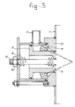
- Figure 3 shows a longitudinal section of a sprayer according to the invention which is in fact suitable for a kettle provided with a scraping mechanism and which is intended, in particular, for thick substances, sugar crystals, jam or the like.
- The sprayer according to Figure 1 is installed in the wall, generally double, of a kettle bounded by the inside wall 1 and the
outside wall 2. - The housing of the sprayer comprises a thick-
walled part 3 between thewalls 1 and 2 and a thin-walled part 4 outside theoutside wall 2. - A
medium feed 5 connects to thepart 3. The thick-walled part 3 is constructed as a cylinder. - In the interior of the
housing 3, 4, there is a rod-type element 6 which can be moved axially and which is preloaded by a spring 7 and atransverse wall 8 in the inward direction. - At the end facing the wall 1, the
element 6 comprises apiston 9 with a number of axially extendingpassages 10 and aconical sealing part 11. - In the closed, nonoperating position, the wider edge of the sealing
part 11 is up against a sloping edge of anelement 12 fixed to thehousing part 3. - Diverse seals are also furthermore present.
- The sprayer according to Figure 1 is shown in the nonoperating position, the face of the head of the sealing
part 11 lying in one plane with the inside of the wall 1. - If pressurized cleaning medium is supplied via the connection, pressure is exerted on the sealing
part 11 as a result of which it moves outwards into the kettle against the action of the spring 7. - At the same time, the medium passes through the
openings 10 and is injected as a cone into the kettle via the conical annular gap between thesealing part 11 and thefixed element 12. - Because the sealing
part 11 projects into the kettle beyond the inside of the wall 1 in the operating position, this embodiment is not suitable for a kettle in which a scraping mechanism, which is not shown, is up against the inside of the wall 1. - This is, however, the case in the embodiment according to Figure 2.
- Installed in the
cylinder 3 is a differential piston comprising alarger part 13 and asmaller part 14. Thepiston spring 15 which rests against atransverse wall 16. - Screwed into said
transverse wall 16 is anelement 17 which extends axially in thehousing part 3 and terminates in aconical sealing part 18 which can interact with an end rim of thethinner piston part 14. - The
element transverse wall 16 in a manner such that the end face of the sealingpart 18 lies in one plane with the inside of the wall 1. - Arranged in the wall of the
piston part 14 arechannels 19 which are distributed over the circumfer ence. Saidchannels 19 extend obliquely in the direction of the kettle. - They may extend in radial planes or in tangential planes.
- In the last case, the
piston - As a result of the shape of the end rim of the
thinner piston part 14, saidpart 14 is also unable to project beyond the inside of the wall 1 under the influence of thespring 15. - When pressurized cleaning medium is supplied via the
connection 5, thepiston spring 15. - A conical annular gap is therefore made free between the inside of the
piston part 14 and the outside of the sealingpart 18. - A conical jet, which optionally rotates, is there fore produced.
- In this embodiment nothing extends out inside the inside of the wall 1 even in the operating position. Scraping elements are therefore not impeded.
- This applies also to the embodiment according to Figure 3. This embodiment is intended primarily for kettles in which thick substances, such as sugar crystals and jam are processed.
- In this case, a multiplicity of directed jets are obtained.
- In this embodiment, the
differential piston compression spring 15, but the nonoperating end position is reached when the nut 20 on therod 21 comes up against thetransverse wall 16. Therod 21 is firmly joined to thepiston part 14. - In this position, the face of the head of the
piston part 14 lies in one plane with thepart 22 which is joined to the wall 1 and does not therefore impede any scraping element. - The spray opening is formed in this embodiment when the
piston spring 16. - Obliquely and/or tangentially extending channels provide jets which spray alongside each other.
- Obviously, several spray heads may be installed in the wall of a kettle.
Claims (8)
1. Kettle for the preparation and/or processing of viscous foodstuffs, such as cream, condensed milk, jam and the like, provided with spraying means for cleaning the interior of the kettle, and optionally provided with a stirring mechanism and/or scraping mechanism, characterized in that spraying heads which, at least in the nonoperating position, lie in one plane with the inside of the wall are installed at one or more points in the wall of the kettle.
2. Kettle according to Claim 1, characterized in that the spraying head or heads do not project beyond the inside of the wall even in the operating position.
3. Kettle according to Claim 1 or 2, characterized in that the spraying head comprises a cylinder which is set up transversely to the wall of the kettle, the end of the cylinder facing the kettle lying in one plane with the inside of the wall, to which cylinder a feed for pressurized cleaning medium is connected and in which cylinder a piston is movably provided with a sealing part in order to be able to seal the said end of the cylinder, the piston being loaded in one direction by the medium and in the other direction by a spring or the like.
4. Kettle according to Claim 1 or 3, characterized in that the piston is provided with channels for allowing the cleaning medium through and forms one entity with a conical sealing part, with the largest diameter at the side facing away from the piston, which sealing part projects beyond the inside of the wall of the kettle in the operating position.
5. Kettle according to Claim 1, 2 or 3 characterized in that the piston is constructed as a differential piston which is loaded Δby the spring to the position in which the end of the head of the piston lies in one plane with the inside of the kettle wall but is unable to pass said position.
6. Kettle according to Claim 5, characterized in that the conical sealing part is installed in a fixed position and the largest diameter thereof forms a stop for the piston and, in the position in which the piston is retracted by means of the pressurized cleaning medium, forms an annular spray opening with the inside of the piston.
7. Kettle according to Claim 5 or 6, characterized in that channels are formed in the thinner part of the differential piston to allow pressurized cleaning medium through into the interior of the differential piston.
8. Kettle according to Claim 7, characterized in that the channels extend tangentially in order to generate rotating spray jets.
Applications Claiming Priority (2)
| Application Number | Priority Date | Filing Date | Title |
|---|---|---|---|
| NL8702319A NL8702319A (en) | 1987-09-29 | 1987-09-29 | BOILER WITH AGENT AND SPRAY AGENTS. |
| NL8702319 | 1987-09-29 |
Publications (1)
| Publication Number | Publication Date |
|---|---|
| EP0310185A1 true EP0310185A1 (en) | 1989-04-05 |
Family
ID=19850678
Family Applications (1)
| Application Number | Title | Priority Date | Filing Date |
|---|---|---|---|
| EP88202091A Withdrawn EP0310185A1 (en) | 1987-09-29 | 1988-09-26 | Kettle with stirring mechanism and spraying means |
Country Status (2)
| Country | Link |
|---|---|
| EP (1) | EP0310185A1 (en) |
| NL (1) | NL8702319A (en) |
Cited By (6)
| Publication number | Priority date | Publication date | Assignee | Title |
|---|---|---|---|---|
| WO1999064175A1 (en) * | 1998-06-05 | 1999-12-16 | Matcon (R & D) Limited | Fluid flow apparatus |
| CN100411754C (en) * | 2003-04-08 | 2008-08-20 | 李树 | Container washing device |
| EP3075459A1 (en) * | 2015-03-30 | 2016-10-05 | Alfa Laval Corporate AB | Fluid ejection apparatus |
| WO2018145711A3 (en) * | 2017-02-07 | 2018-09-20 | Jens Andersen | Tank cleaning nozzle, tank comprising it and method for cleaning a tank |
| EP3824996A1 (en) | 2019-11-21 | 2021-05-26 | Alfa Laval Corporate AB | A tank cleaning nozzle |
| CN118287025A (en) * | 2024-06-06 | 2024-07-05 | 汇鑫生物科技有限公司 | Esterification method and equipment for vitamin D2 production |
Citations (5)
| Publication number | Priority date | Publication date | Assignee | Title |
|---|---|---|---|---|
| US2909325A (en) * | 1957-03-26 | 1959-10-20 | Edwin J Hunter | Sprinkler head |
| US3804338A (en) * | 1973-01-10 | 1974-04-16 | Fetterolf John S | Combined tank rinsing valve |
| US4046155A (en) * | 1974-12-30 | 1977-09-06 | Stal-Laval Turbin Ab | Washing apparatus for a compound compressor |
| DE2641425A1 (en) * | 1976-09-15 | 1978-03-16 | Kloeckner Humboldt Deutz Ag | Turbine cleaning machine with liq. dispensing nozzles - has spring biased protective cover over nozzle orifices movable only by pressure of cleaning liq. |
| CH603031A5 (en) * | 1977-04-15 | 1978-08-15 | Jean Jacques Goavec |
-
1987
- 1987-09-29 NL NL8702319A patent/NL8702319A/en not_active Application Discontinuation
-
1988
- 1988-09-26 EP EP88202091A patent/EP0310185A1/en not_active Withdrawn
Patent Citations (5)
| Publication number | Priority date | Publication date | Assignee | Title |
|---|---|---|---|---|
| US2909325A (en) * | 1957-03-26 | 1959-10-20 | Edwin J Hunter | Sprinkler head |
| US3804338A (en) * | 1973-01-10 | 1974-04-16 | Fetterolf John S | Combined tank rinsing valve |
| US4046155A (en) * | 1974-12-30 | 1977-09-06 | Stal-Laval Turbin Ab | Washing apparatus for a compound compressor |
| DE2641425A1 (en) * | 1976-09-15 | 1978-03-16 | Kloeckner Humboldt Deutz Ag | Turbine cleaning machine with liq. dispensing nozzles - has spring biased protective cover over nozzle orifices movable only by pressure of cleaning liq. |
| CH603031A5 (en) * | 1977-04-15 | 1978-08-15 | Jean Jacques Goavec |
Cited By (12)
| Publication number | Priority date | Publication date | Assignee | Title |
|---|---|---|---|---|
| WO1999064175A1 (en) * | 1998-06-05 | 1999-12-16 | Matcon (R & D) Limited | Fluid flow apparatus |
| CN100411754C (en) * | 2003-04-08 | 2008-08-20 | 李树 | Container washing device |
| EP3075459A1 (en) * | 2015-03-30 | 2016-10-05 | Alfa Laval Corporate AB | Fluid ejection apparatus |
| EP3075460A1 (en) * | 2015-03-30 | 2016-10-05 | Alfa Laval Corporate AB | Fluid ejection apparatus |
| CN106000709A (en) * | 2015-03-30 | 2016-10-12 | 阿尔法拉瓦尔股份有限公司 | Fluid ejection apparatus |
| WO2018145711A3 (en) * | 2017-02-07 | 2018-09-20 | Jens Andersen | Tank cleaning nozzle, tank comprising it and method for cleaning a tank |
| CN110312577A (en) * | 2017-02-07 | 2019-10-08 | 基伊埃图亨哈根有限责任公司 | Tank cleaning nozzle, the tank comprising it and method for cleaning tank |
| JP2020506041A (en) * | 2017-02-07 | 2020-02-27 | ゲーエーアー トゥシェンハーゲン ゲーエムベーハー | Tank cleaning nozzle, tank including the nozzle, and tank cleaning method |
| US11167329B2 (en) | 2017-02-07 | 2021-11-09 | Gea Tuchenhagen Gmbh | Tank cleaning nozzle, tank comprising it and method for cleaning a tank |
| EP3579984B1 (en) | 2017-02-07 | 2024-11-06 | GEA Tuchenhagen GmbH | Tank cleaning nozzle, tank comprising it and method for cleaning a tank |
| EP3824996A1 (en) | 2019-11-21 | 2021-05-26 | Alfa Laval Corporate AB | A tank cleaning nozzle |
| CN118287025A (en) * | 2024-06-06 | 2024-07-05 | 汇鑫生物科技有限公司 | Esterification method and equipment for vitamin D2 production |
Also Published As
| Publication number | Publication date |
|---|---|
| NL8702319A (en) | 1989-04-17 |
Similar Documents
| Publication | Publication Date | Title |
|---|---|---|
| EP1731081B1 (en) | Dishwasher | |
| EP0974302B1 (en) | Spray device for dishwasher | |
| DE69023477T2 (en) | TEMPERATURE-CONTROLLED FOOD TREATMENT DEVICE AND METHOD. | |
| EP0310185A1 (en) | Kettle with stirring mechanism and spraying means | |
| US5397471A (en) | Self-cleaning scroll and screen centrifuge | |
| DE69126742T2 (en) | Continuous dryer | |
| EP3765181B1 (en) | Hygienic mixer | |
| EP0138188B1 (en) | Pressure filter | |
| CN110312577B (en) | Tank cleaning nozzle, tank comprising same and method for cleaning tank | |
| DE9315698U1 (en) | Evaporator flask for a rotary evaporator | |
| DE3915354A1 (en) | VIBRATION SCREEN WITH FILTER AND METHOD FOR CLEANING THE FILTER | |
| JPH0335988B2 (en) | ||
| EP1984127B1 (en) | A cleaning assembly | |
| JPH05227926A (en) | High-pressure processing unit for food or the like | |
| US5565095A (en) | Filter apparatus | |
| DE1933147A1 (en) | Paint spray gun for electrostatic paint spraying | |
| DE69013982T2 (en) | Heat exchanger with scraped surface. | |
| WO1989007978A1 (en) | Fluidized bed installation, in particular for granulating a powder material | |
| WO2023059660A3 (en) | Cleaning mechanism and underdrain for media vessel and method of cleaning | |
| WO2008104267A1 (en) | Rotary tablet press having a washing device | |
| US4676435A (en) | Sprayer head | |
| US6015375A (en) | Centrifuge with a centrifugal drum subdivided into a peeling chamber and a hydrohermetic chamber | |
| US2342892A (en) | Grater for removing and flaking edible rinds | |
| US6073363A (en) | Opening/closing device for discharge hole of filter-drier | |
| DE2427053A1 (en) | Viscous material filter chamber - with ultrasonic oscillator for filter element in basket |
Legal Events
| Date | Code | Title | Description |
|---|---|---|---|
| PUAI | Public reference made under article 153(3) epc to a published international application that has entered the european phase |
Free format text: ORIGINAL CODE: 0009012 |
|
| AK | Designated contracting states |
Kind code of ref document: A1 Designated state(s): AT BE CH DE ES FR GB GR IT LI LU NL SE |
|
| 17P | Request for examination filed |
Effective date: 19890920 |
|
| 17Q | First examination report despatched |
Effective date: 19901029 |
|
| RAP1 | Party data changed (applicant data changed or rights of an application transferred) |
Owner name: TERLET N.V. |
|
| STAA | Information on the status of an ep patent application or granted ep patent |
Free format text: STATUS: THE APPLICATION IS DEEMED TO BE WITHDRAWN |
|
| 18D | Application deemed to be withdrawn |
Effective date: 19920620 |