EP3824840A1 - User initiated break-away clutching of a surgical mounting platform - Google Patents
User initiated break-away clutching of a surgical mounting platform Download PDFInfo
- Publication number
- EP3824840A1 EP3824840A1 EP20198221.2A EP20198221A EP3824840A1 EP 3824840 A1 EP3824840 A1 EP 3824840A1 EP 20198221 A EP20198221 A EP 20198221A EP 3824840 A1 EP3824840 A1 EP 3824840A1
- Authority
- EP
- European Patent Office
- Prior art keywords
- linkage
- joint
- manual
- pose
- torque
- Prior art date
- Legal status (The legal status is an assumption and is not a legal conclusion. Google has not performed a legal analysis and makes no representation as to the accuracy of the status listed.)
- Granted
Links
Images




Classifications
-
- A—HUMAN NECESSITIES
- A61—MEDICAL OR VETERINARY SCIENCE; HYGIENE
- A61B—DIAGNOSIS; SURGERY; IDENTIFICATION
- A61B34/00—Computer-aided surgery; Manipulators or robots specially adapted for use in surgery
- A61B34/30—Surgical robots
-
- A—HUMAN NECESSITIES
- A61—MEDICAL OR VETERINARY SCIENCE; HYGIENE
- A61B—DIAGNOSIS; SURGERY; IDENTIFICATION
- A61B34/00—Computer-aided surgery; Manipulators or robots specially adapted for use in surgery
- A61B34/70—Manipulators specially adapted for use in surgery
- A61B34/77—Manipulators with motion or force scaling
-
- A—HUMAN NECESSITIES
- A61—MEDICAL OR VETERINARY SCIENCE; HYGIENE
- A61B—DIAGNOSIS; SURGERY; IDENTIFICATION
- A61B90/00—Instruments, implements or accessories specially adapted for surgery or diagnosis and not covered by any of the groups A61B1/00 - A61B50/00, e.g. for luxation treatment or for protecting wound edges
- A61B90/06—Measuring instruments not otherwise provided for
-
- A—HUMAN NECESSITIES
- A61—MEDICAL OR VETERINARY SCIENCE; HYGIENE
- A61B—DIAGNOSIS; SURGERY; IDENTIFICATION
- A61B90/00—Instruments, implements or accessories specially adapted for surgery or diagnosis and not covered by any of the groups A61B1/00 - A61B50/00, e.g. for luxation treatment or for protecting wound edges
- A61B90/50—Supports for surgical instruments, e.g. articulated arms
-
- B—PERFORMING OPERATIONS; TRANSPORTING
- B25—HAND TOOLS; PORTABLE POWER-DRIVEN TOOLS; MANIPULATORS
- B25J—MANIPULATORS; CHAMBERS PROVIDED WITH MANIPULATION DEVICES
- B25J9/00—Program-controlled manipulators
- B25J9/16—Program controls
- B25J9/1628—Program controls characterised by the control loop
- B25J9/1633—Program controls characterised by the control loop compliant, force, torque control, e.g. combined with position control
-
- B—PERFORMING OPERATIONS; TRANSPORTING
- B25—HAND TOOLS; PORTABLE POWER-DRIVEN TOOLS; MANIPULATORS
- B25J—MANIPULATORS; CHAMBERS PROVIDED WITH MANIPULATION DEVICES
- B25J9/00—Program-controlled manipulators
- B25J9/16—Program controls
- B25J9/1656—Program controls characterised by programming, planning systems for manipulators
- B25J9/1669—Program controls characterised by programming, planning systems for manipulators characterised by special application, e.g. multi-arm co-operation, assembly, grasping
-
- A—HUMAN NECESSITIES
- A61—MEDICAL OR VETERINARY SCIENCE; HYGIENE
- A61B—DIAGNOSIS; SURGERY; IDENTIFICATION
- A61B34/00—Computer-aided surgery; Manipulators or robots specially adapted for use in surgery
- A61B34/30—Surgical robots
- A61B2034/301—Surgical robots for introducing or steering flexible instruments inserted into the body, e.g. catheters or endoscopes
-
- A—HUMAN NECESSITIES
- A61—MEDICAL OR VETERINARY SCIENCE; HYGIENE
- A61B—DIAGNOSIS; SURGERY; IDENTIFICATION
- A61B34/00—Computer-aided surgery; Manipulators or robots specially adapted for use in surgery
- A61B34/30—Surgical robots
- A61B2034/304—Surgical robots including a freely orientable platform, e.g. so called 'Stewart platforms'
-
- A—HUMAN NECESSITIES
- A61—MEDICAL OR VETERINARY SCIENCE; HYGIENE
- A61B—DIAGNOSIS; SURGERY; IDENTIFICATION
- A61B90/00—Instruments, implements or accessories specially adapted for surgery or diagnosis and not covered by any of the groups A61B1/00 - A61B50/00, e.g. for luxation treatment or for protecting wound edges
- A61B90/06—Measuring instruments not otherwise provided for
- A61B2090/064—Measuring instruments not otherwise provided for for measuring force, pressure or mechanical tension
- A61B2090/066—Measuring instruments not otherwise provided for for measuring force, pressure or mechanical tension for measuring torque
-
- A—HUMAN NECESSITIES
- A61—MEDICAL OR VETERINARY SCIENCE; HYGIENE
- A61B—DIAGNOSIS; SURGERY; IDENTIFICATION
- A61B90/00—Instruments, implements or accessories specially adapted for surgery or diagnosis and not covered by any of the groups A61B1/00 - A61B50/00, e.g. for luxation treatment or for protecting wound edges
- A61B90/50—Supports for surgical instruments, e.g. articulated arms
- A61B2090/508—Supports for surgical instruments, e.g. articulated arms with releasable brake mechanisms
-
- A—HUMAN NECESSITIES
- A61—MEDICAL OR VETERINARY SCIENCE; HYGIENE
- A61B—DIAGNOSIS; SURGERY; IDENTIFICATION
- A61B34/00—Computer-aided surgery; Manipulators or robots specially adapted for use in surgery
- A61B34/30—Surgical robots
- A61B34/35—Surgical robots for telesurgery
-
- A—HUMAN NECESSITIES
- A61—MEDICAL OR VETERINARY SCIENCE; HYGIENE
- A61B—DIAGNOSIS; SURGERY; IDENTIFICATION
- A61B34/00—Computer-aided surgery; Manipulators or robots specially adapted for use in surgery
- A61B34/30—Surgical robots
- A61B34/37—Leader-follower robots
-
- G—PHYSICS
- G05—CONTROLLING; REGULATING
- G05B—CONTROL OR REGULATING SYSTEMS IN GENERAL; FUNCTIONAL ELEMENTS OF SUCH SYSTEMS; MONITORING OR TESTING ARRANGEMENTS FOR SUCH SYSTEMS OR ELEMENTS
- G05B2219/00—Program-control systems
- G05B2219/30—Nc systems
- G05B2219/40—Robotics, robotics mapping to robotics vision
- G05B2219/40414—Man robot interface, exchange of information between operator and robot
-
- Y—GENERAL TAGGING OF NEW TECHNOLOGICAL DEVELOPMENTS; GENERAL TAGGING OF CROSS-SECTIONAL TECHNOLOGIES SPANNING OVER SEVERAL SECTIONS OF THE IPC; TECHNICAL SUBJECTS COVERED BY FORMER USPC CROSS-REFERENCE ART COLLECTIONS [XRACs] AND DIGESTS
- Y10—TECHNICAL SUBJECTS COVERED BY FORMER USPC
- Y10S—TECHNICAL SUBJECTS COVERED BY FORMER USPC CROSS-REFERENCE ART COLLECTIONS [XRACs] AND DIGESTS
- Y10S901/00—Robots
- Y10S901/02—Arm motion controller
Definitions
- Minimally invasive medical techniques are intended to reduce the amount of extraneous tissue that is damaged during diagnostic or surgical procedures, thereby reducing patient recovery time, discomfort, and deleterious side effects.
- One effect of minimally invasive surgery for example, is reduced post-operative hospital recovery times. Because the average hospital stay for a standard surgery is typically significantly longer than the average stay for an analogous minimally invasive surgery, increased use of minimally invasive techniques could save millions of dollars in hospital costs each year. While many of the surgeries performed each year in the United States could potentially be performed in a minimally invasive manner, only a portion of the current surgeries use these advantageous techniques due to limitations in minimally invasive surgical instruments and the additional surgical training involved in mastering them.
- Minimally invasive robotic surgical or telesurgical systems have been developed to increase a surgeon's dexterity and avoid some of the limitations on traditional minimally invasive techniques.
- the surgeon uses some form of remote control (e.g., a servomechanism or the like) to manipulate surgical instrument movements, rather than directly holding and moving the instruments by hand.
- the surgeon can be provided with an image of the surgical site at a surgical workstation. While viewing a two or three dimensional image of the surgical site on a display, the surgeon performs the surgical procedures on the patient by manipulating master control devices, which in turn control motion of the servo-mechanically operated instruments.
- the servomechanism used for telesurgery will often accept input from two master controllers (one for each of the surgeon's hands) and may include two or more robotic arms on each of which a surgical instrument is mounted. Operative communication between master controllers and associated robotic arm and instrument assemblies is typically achieved through a control system.
- the control system typically includes at least one processor that relays input commands from the master controllers to the associated robotic arm and instrument assemblies and back from the instrument and arm assemblies to the associated master controllers in the case of, for example, force feedback or the like.
- One example of a robotic surgical system is the DA VINCI® system available from Intuitive Surgical, Inc. of Sunnyvale, Calif.
- the driven linkage or "slave” is often called a robotic surgical manipulator, and exemplary linkage arrangements for use as a robotic surgical manipulator during minimally invasive robotic surgery are described in U.S. Pat. Nos. 7,594,912 ; 6,758,843 ; 6,246,200 ; and 5,800,423 ; the full disclosures of which are incorporated herein by reference.
- These linkages often make use of a parallelogram arrangement to hold an instrument having a shaft.
- Such a manipulator structure can constrain movement of the instrument so that the instrument pivots about a remote center of manipulation positioned in space along the length of the rigid shaft.
- an end effector of the surgical instrument can be positioned safely by moving the proximal end of the shaft using the manipulator linkage without imposing potentially dangerous forces against the abdominal wall.
- Alternative manipulator structures are described, for example, in U.S. Pat. Nos. 7,763,015 ; 6,702,805 ; 6,676,669 ; 5,855,583 ; 5,808,665 ; 5,445,166 ; and 5,184,601 ; the full disclosures of which are incorporated herein by reference.
- a variety of structural arrangements can also be used to support and position the robotic surgical manipulator and the surgical instrument at the surgical site during robotic surgery.
- Supporting linkage mechanisms sometimes referred to as set-up joints, or set-up joint arms, are often used to position and align each manipulator with the respective incision point in a patient's body.
- the supporting linkage mechanism facilitates the alignment of a surgical manipulator with a desired surgical incision point and targeted anatomy. Exemplary supporting linkage mechanisms are described in U.S. Pat. Nos. 6,246,200 and 6,788,018 , the full disclosures of which are incorporated herein by reference.
- the present invention generally provides improved robotic and/or surgical devices, systems, and methods.
- Kinematic linkage structures and associated control systems described herein are particularly beneficial in helping system users to arrange the robotic structure in preparation for use, including in preparation for a surgical procedure on a particular patient.
- Exemplary robotic surgical systems described herein may have one or more kinematic linkage subsystems that are configured to help align a manipulator structure with the surgical work site.
- the joints of these set-up systems may be actively driven, passive (so that they are manually articulated and then locked into the desired configuration while the manipulator is used therapeutically), or a mix of both.
- Embodiments of the robotic systems described herein may employ a set-up mode in which one or more joints are initially held static by a brake or joint drive system.
- Inadvertent articulation is limited by the brake or drive system, but the user can manually articulate the joint(s) by manually pushing against the linkage with a force, torque, or the like that exceeds a manual articulation threshold of the joint(s).
- a processor may facilitate articulation with less user effort by modifying the signals transmitted to the brake or drive system.
- the system may sense that the user has completed the reconfiguration from a velocity of the joint(s) below a threshold, optionally for a desired dwell time. The system may then again inhibit inadvertent articulation of the joint(s.
- the dwell time can help avoid locking the linkage when reversing directions, and the system can provide a "detent" like manual articulation that is not limited to mechanically pre-defined detent joint configurations.
- Embodiments of the invention provide a user interface is intuitive, and can be particularly well-suited for manual movement of a platform supporting a plurality of surgical manipulators in a robotic surgical system or the like without having to add additional input devices.
- the invention provides a method for configuring a robotic system.
- the method comprises inhibiting manual articulation of a linkage of the system from a first pose in response to a first manual effort against the linkage being below a desired articulation threshold.
- a manual movement of the linkage from the first pose toward a second pose is facilitated in response to a second manual effort to articulate the linkage exceeding the desired articulation threshold.
- the second pose is determined in response to the manual movement of the linkage. Manual movement of the linkage from the second pose is inhibited.
- a method for configuring a robotic system includes inhibiting manual articulation of a linkage of the system from a first pose in response to a first manual effort against the linkage, facilitating a manual movement of the linkage from the first pose toward a second pose, determining the second pose in response to the manual movement of the linkage, and inhibiting manual movement of the linkage from the second pose.
- the inhibiting step is in response to a first manual effort against the linkage that is below a desired articulation threshold.
- the facilitating step is in response to a second manual effort against the linkage that exceeds the desired articulation threshold.
- a joint sensor may sense a first torque of the first manual effort applied to a joint and a processor may inhibit the manual articulation by determining drive signals configured to induce a counteracting torque to the linkage opposing the first torque so as to urge the linkage back toward the first pose.
- the joint sensor may also sense the second torque of the second manual effort applied to the joint and the processor may be configured to determine that the second effort exceeds the desired articulation threshold.
- the articulation threshold may be a torque threshold and the processor may determine that the second effort exceeds the desired articulation threshold by determining that the second torque exceeds the threshold torque.
- the processor may alter the drive signals so as to decrease the counteracting torque so that the first torque is sufficient to manually move the manipulator.
- a processor may alter drive signals in response to the second effort exceeding the desired articulation threshold by adding a friction compensation component to the drive signals so as to mitigate friction of the linkage for the manual movement toward the second pose.
- the second pose may be determined by determining that a velocity of the manual movement is below a threshold velocity. Additionally, the second pose may also be determined by determining that the velocity of the manual movement remains below the threshold velocity for a threshold dwell time so as to facilitate reversing a direction of the movement without inhibiting manual movement.
- the method for configuring a robotic system includes driving the linkage in the second pose with drive signals so as to inhibit manual movement of the linkage from the second pose in response to a third manual effort against the manipulator being below the desired articulation threshold.
- the linkage may be a set-up structure having a proximal base and a platform with the joint disposed therebetween.
- the platform may support a plurality of surgical manipulators, where each manipulator may be an instrument holder configured to releasably receive a surgical instrument.
- the manual movement may be a movement that alters positions of the plurality of manipulators relative to a surgical site.
- the linkage may be included in a surgical manipulator having a holder for releasably receiving a surgical instrument.
- the surgical manipulator may also include a cannula interface configured for releasably receiving a cannula.
- the manipulator may be further configured to pivotably move a shaft of the instrument within an aperture adjacent the cannula so as to manipulate an end effector of the instrument within a minimally invasive surgical aperture.
- the configuration method may further include inhibiting manual articulation of the joint with manual effort exceeding the desired articulation threshold in response to the mounting of the cannula to the cannula interface.
- a robotic system in another aspect, includes a linkage having a joint, a drive or brake system coupled to the linkage, and a processor coupled with the drive or brake system.
- the processor may be configured to transmit signals to the drive or brake system so as to inhibit manual articulation of the linkage from a first pose in response to a first manual effort against the linkage being below a desired articulation threshold.
- the processor may alter the signals in response to a second manual effort to articulate the linkage exceeding the desired articulation threshold.
- the altered signals may be configured to facilitate a manual movement of the linkage from the first pose toward a second pose.
- the processor may also determine the second pose in response to the manual movement of the linkage and may transmit the signals to the drive system so as to inhibit manual movement of the linkage from the second pose.
- the robotic system further includes a joint sensor coupled to the joint.
- the joint sensor may be configured to sense a first torque of the first manual effort applied to the joint.
- the processor may be configured to determine the signals so as to apply a counteracting torque to the linkage opposing the first torque and urge the linkage back toward the first pose.
- a drive or brake system may include a drive system.
- the joint sensor may be configured so as to transmit to the processor a second torque of the second manual effort applied to the joint.
- the processor may be further configured to determine if the second effort exceeds the desired articulation threshold using the second torque.
- the processor may be configured to determine that the second effort exceeds the desired articulation threshold by determining whether the second torque exceeds a threshold torque.
- the processor may alter the drive signals so as to decrease the counteracting torque so that the first torque is sufficient to manually move the manipulator.
- the signals of the robotic system may include drive signals and the processor may be configured to alter the drive signals in response to the second effort exceeding the desired articulation threshold by adding a friction compensation component to the drive signals so as to mitigate friction of the linkage for the manual movement toward the second pose.
- the processor may be configured to determine a second pose in response to a velocity of the manual movement being below a threshold velocity.
- the processor may be further configured to determine the second pose by determining that the velocity of the manual movement is below the threshold velocity for a threshold dwell time so as to facilitate a reversal of a direction of the manual movement without inhibiting the manual movement.
- the processor may also be configured to inhibit manual movement of the linkage from the second pose in response to a third manual effort against the manipulator being below the desired articulation threshold.
- the above exemplary system may be a surgical robotic system.
- the linkage may be a set-up structure having a proximal base and a platform with the joint disposed therebetween.
- the platform may support a plurality of surgical manipulators, where each manipulator may be an instrument holder configured to releasably receive a surgical instrument.
- the manual movement may be a movement that alters positions of the plurality of manipulators relative to a surgical site.
- the linkage may be included in a surgical manipulator having a holder for releasably receiving a surgical instrument.
- the surgical manipulator may also include a cannula interface configured for releasably receiving a cannula.
- the manipulator may be further configured to pivotably move a shaft of the instrument within an aperture adjacent the cannula so as to manipulate an end effector of the instrument within a minimally invasive surgical aperture.
- the system may further include inhibiting manual articulation of the joint with manual effort exceeding the desired articulation threshold in response to the mounting of the cannula to the cannula interface.
- a robotic surgical system in an additional aspect, includes a linkage having a joint, a drive system coupled to the linkage, a torque sensor system coupled to the joint, and a processor coupling the torque sensor with the drive system.
- the joint may be disposed between a proximal base and an instrument holder.
- the instrument holder may be configured for releasably supporting a surgical instrument.
- the processor is configured to transmit drive signals to the drive system so as to inhibit manual articulation of the joint from a first configuration in response to a sensed torque being below a desired articulation threshold.
- the processor may alter the drive signals to facilitate a manual movement of the joint from the first configuration toward a second configuration using a movement torque lower than the articulation threshold.
- the processor may determine the second configuration.
- the processor may also be configured to transmit drive signals to the drive system so as to inhibit manual movement of the linkage from the second pose in response to a sensed torque being below a desired articulation threshold.
- a method of configuring a robotic system includes driving a robotic assembly during manual efforts to move a linkage of the assembly so as to simulate a first and second detent of the linkage at first and second linkage poses.
- the method also includes determining the second pose in response to a manual movement of the linkage to the second pose.
- robotic surgical systems may have one or more kinematic linkage systems that are configured to support and help align the manipulator structure with the surgical work site.
- These set-up systems may be actively driven or may be passive, so that they are manually articulated and then locked into the desired configuration while the manipulator is used therapeutically.
- the passive set-up kinematic systems may have advantages in size, weight, complexity, and cost.
- manipulators may be used to treat tissues of each patient, the manipulators may each independently benefit from accurate positioning so as to allow the instrument supported by that instrument to have the desired motion throughout the workspace, and minor changes in the relative locations of adjacent manipulators may have significant impact on the interactions between manipulators (with poorly positioned manipulators potentially colliding or having their range and/or ease of motion significantly reduced).
- the challenges of quickly arranging the robotic system in preparation for surgery can be significant.
- One option is to mount multiple manipulators to a single platform, with the manipulator-supporting platform sometimes being referred to as an orienting platform.
- the orienting platform can be supported by an actively driven support linkage (sometimes referred to herein as a set-up structure, and typically having a set-up structure linkage, etc.)
- the system may also provide and control motorized axes of the robotic set-up structure supporting the orienting platform with some kind of joystick or set of buttons that would allow the user to actively drive those axes as desired in an independent fashion.
- This approach while useful in some situations, may suffer from some disadvantages.
- buttons having different functions While individual clutch buttons might also be used to release the brake or drive system, the possibility of confusion may remain between buttons having different functions.
- both sterile and non-sterile members of a surgical team may want to articulate some joints or linkages (such as by grabbing differing locations inside or outside the sterile field). Hence a more intuitive and flexible user interface would be desirable. This is particularly true of an orienting platform for use in multi-quadrant surgery, or for a structure that supports a plurality of surgical manipulators and may pivot about an axis extending at least roughly vertically so as to orient the manipulators relative to a patient on a surgical table or other support.
- FIG. 1 is a plan view illustration of a Minimally Invasive Robotic Surgical (MIRS) system 10, typically used for performing a minimally invasive diagnostic or surgical procedure on a Patient 12 who is lying down on an Operating table 14.
- the system can include a Surgeon's Console 16 for use by a Surgeon 18 during the procedure.
- One or more Assistants 20 may also participate in the procedure.
- the MIRS system 10 can further include a Patient Side Cart 22 (surgical robot) and an Electronics Cart 24.
- the Patient Side Cart 22 can manipulate at least one removably coupled tool assembly 26 (hereinafter simply referred to as a "tool") through a minimally invasive incision in the body of the Patient 12 while the Surgeon 18 views the surgical site through the Console 16.
- An image of the surgical site can be obtained by an endoscope 28, such as a stereoscopic endoscope, which can be manipulated by the Patient Side Cart 22 to orient the endoscope 28.
- the Electronics Cart 24 can be used to process the images of the surgical site for subsequent display to the Surgeon 18 through the Surgeon's Console 16.
- the number of surgical tools 26 used at one time will generally depend on the diagnostic or surgical procedure and the space constraints within the operating room among other factors. If it is necessary to change one or more of the tools 26 being used during a procedure, an Assistant 20 may remove the tool 26 from the Patient Side Cart 22, and replace it with another tool 26 from a tray 30 in the operating room.
- FIG. 2 is a perspective view of the Surgeon's Console 16.
- the Surgeon's Console 16 includes a left eye display 32 and a right eye display 34 for presenting the Surgeon 18 with a coordinated stereo view of the surgical site that enables depth perception.
- the Console 16 further includes one or more input control devices 36, which in turn cause the Patient Side Cart 22 (shown in FIG. 1 ) to manipulate one or more tools.
- the input control devices 36 can provide the same degrees of freedom as their associated tools 26 (shown in FIG. 1 ) to provide the Surgeon with telepresence, or the perception that the input control devices 36 are integral with the tools 26 so that the Surgeon has a strong sense of directly controlling the tools 26.
- position, force, and tactile feedback sensors may be employed to transmit position, force, and tactile sensations from the tools 26 back to the Surgeon's hands through the input control devices 36.
- the Surgeon's Console 16 is usually located in the same room as the patient so that the Surgeon may directly monitor the procedure, be physically present if necessary, and speak to an Assistant directly rather than over the telephone or other communication medium. However, the Surgeon can be located in a different room, a completely different building, or other remote location from the Patient allowing for remote surgical procedures.
- FIG. 3 is a perspective view of the Electronics Cart 24.
- the Electronics Cart 24 can be coupled with the endoscope 28 and can include a processor to process captured images for subsequent display, such as to a Surgeon on the Surgeon's Console, or on another suitable display located locally and/or remotely.
- the Electronics Cart 24 can process the captured images to present the Surgeon with coordinated stereo images of the surgical site.
- Such coordination can include alignment between the opposing images and can include adjusting the stereo working distance of the stereoscopic endoscope.
- image processing can include the use of previously determined camera calibration parameters to compensate for imaging errors of the image capture device, such as optical aberrations.
- FIG. 4 diagrammatically illustrates a robotic surgery system 50 (such as MIRS system 10 of FIG. 1 ).
- a Surgeon's Console 52 (such as Surgeon's Console 16 in FIG. 1 ) can be used by a Surgeon to control a Patient Side Cart (Surgical Robot) 54 (such as Patent Side Cart 22 in FIG. 1 ) during a minimally invasive procedure.
- the Patient Side Cart 54 can use an imaging device, such as a stereoscopic endoscope, to capture images of the procedure site and output the captured images to an Electronics Cart 56 (such as the Electronics Cart 24 in FIG. 1 ).
- the Electronics Cart 56 can process the captured images in a variety of ways prior to any subsequent display.
- the Electronics Cart 56 can overlay the captured images with a virtual control interface prior to displaying the combined images to the Surgeon via the Surgeon's Console 52.
- the Patient Side Cart 54 can output the captured images for processing outside the Electronics Cart 56.
- the Patient Side Cart 54 can output the captured images to a processor 58, which can be used to process the captured images.
- the images can also be processed by a combination the Electronics Cart 56 and the processor 58, which can be coupled together to process the captured images jointly, sequentially, and/or combinations thereof.
- One or more separate displays 60 can also be coupled with the processor 58 and/or the Electronics Cart 56 for local and/or remote display of images, such as images of the procedure site, or other related images.
- Processor 58 will typically include a combination of hardware and software, with the software comprising tangible media embodying computer readable code instructions for performing the method steps of the control functionally described herein.
- the hardware typically includes one or more data processing boards, which may be co-located but will often have components distributed among the robotic structures described herein.
- the software will often comprise a nonvolatile media, and could also comprise a monolithic code but will more typically comprise a number of subroutines, optionally running in any of a wide variety of distributed data processing architectures.
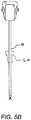
- FIGS. 5A and 5B show a Patient Side Cart 22 and a surgical tool 62, respectively.
- the surgical tool 62 is an example of the surgical tools 26.
- the Patient Side Cart 22 shown provides for the manipulation of three surgical tools 26 and an imaging device 28, such as a stereoscopic endoscope used for the capture of images of the site of the procedure. Manipulation is provided by robotic mechanisms having a number of robotic joints.
- the imaging device 28 and the surgical tools 26 can be positioned and manipulated through incisions in the patient so that a kinematic remote center is maintained at the incision to minimize the size of the incision.
- Images of the surgical site can include images of the distal ends of the surgical tools 26 when they are positioned within the field-of-view of the imaging device 28.
- Surgical tools 26 are inserted into the patient by inserting a tubular cannula 64 through a minimally invasive access aperture such as an incision, natural orifice, percutaneous penetration, or the like.
- Cannula 64 is mounted to the robotic manipulator arm and the shaft of surgical tool 26 passes through the lumen of the cannula.
- the manipulator arm may transmit signals indicating that the cannula has been mounted thereon.
- FIG. 6 is a perspective schematic representation of a robotic surgery system 70, in accordance with many embodiments.
- the surgery system 70 includes a mounting base 72, a support linkage 74, an orienting platform 76, a plurality of outer set-up linkages 78 (two shown), a plurality of inner set-up linkages 80 (two shown), and a plurality of surgical instrument manipulators 82.
- Each of the manipulators 82 is operable to selectively articulate a surgical instrument mounted to the manipulator 82 and insertable into a patient along an insertion axis.
- Each of the manipulators 82 is attached to and supported by one of the set-up linkages 78, 80.
- Each of the outer set-up linkages 78 is rotationally coupled to and supported by the orienting platform 76 by a first set-up linkage joint 84.
- Each of the inner set-up linkages 80 is fixedly attached to and supported by the orienting platform 76.
- the orienting platform 76 is rotationally coupled to and supported by the support linkage 74.
- the support linkage 74 is fixedly attached to and supported by the mounting base 72.
- the mounting base 72 is a movable and floor supported, thereby enabling selective repositioning of the overall surgery system 70, for example, within an operating room.
- the mounting base 72 can include a steerable wheel assembly and/or any other suitable support features that provide for both selective repositioning as well as selectively preventing movement of the mounting base 72 from a selected position.
- the mounting base 72 can also have other suitable configurations, for example, a ceiling mount, fixed floor/pedestal mount, a wall mount, or an interface configured for being supported by any other suitable mounting surface.
- the support linkage 74 is operable to selectively position and/or orient the orienting platform 76 relative to the mounting base 72.
- the support linkage 74 includes a column base 86, a translatable column member 88, a shoulder joint 90, a boom base member 92, a boom first stage member 94, a boom second stage member 96, and a wrist joint 98.
- the column base 86 is fixedly attached to the mounting base 72.
- the translatable column member 88 is slideably coupled to the column base 86 for translation relative to column base 86. In many embodiments, the translatable column member 88 translates relative to the column base 86 along a vertically oriented axis.
- the boom base member 92 is rotationally coupled to the translatable column member 88 by the shoulder joint 90.
- the shoulder joint 90 is operable to selectively orient the boom base member 92 in a horizontal plane relative to the translatable column member 88, which has a fixed angular orientation relative to the column base 86 and the mounting base 72.
- the boom first stage member 94 is selectively translatable relative to the boom base member 92 in a horizontal direction, which in many embodiments is aligned with both the boom base member 92 and the boom first stage member 94.
- the boom second stage member 96 is likewise selectively translatable relative to the boom first stage member 94 in a horizontal direction, which in many embodiments is aligned with the boom first stage member 94 and the boom second stage member 96.
- the support linkage 74 is operable to selectively set the distance between the shoulder joint 90 and the distal end of the boom second stage member 96.
- the wrist joint 98 rotationally couples the distal end of the boom second stage member 96 to the orienting platform 76.
- the wrist joint 98 is operable to selectively set the angular orientation of the orienting platform 76 relative to the mounting base 72.
- Each of the set-up linkages 78, 80 is operable to selectively position and/or orient the associated manipulator 82 relative to the orienting platform 76.
- Each of the set-up linkages 78, 80 includes a set-up linkage base link 100, a set-up linkage extension link 102, a set-up linkage parallelogram linkage portion 104, a set-up linkage vertical link 106, a second set-up linkage joint 108, and a manipulator support link 110.
- each of the set-up linkage base links 100 of the outer set-up linkages 78 can be selectively oriented relative to the orienting platform 76 via the operation of the a first set-up linkage joint 84.
- each of the set-up linkage base links 100 of the inner set-up linkages 80 is fixedly attached to the orienting platform 76.
- Each of the inner set-up linkages 80 can also be rotationally attached to the orienting platform 76 similar to the outer set-up linkages via an additional first set-up linkage joints 84.
- Each of the set-up linkage extension links 102 is translatable relative to the associated set-up linkage base link 100 in a horizontal direction, which in many embodiments is aligned with the associated set-up linkage base link and the set-up linkage extension link 102.
- each of the set-up linkage parallelogram linkage portions 104 configured and operable to selectively translate the set-up linkage vertical link 106 in a vertical direction while keeping the set-up linkage vertical link 106 vertically oriented.
- each of the set-up linkage parallelogram linkage portions 104 includes a first parallelogram joint 112, a coupling link 114, and a second parallelogram 116.
- the first parallelogram joint 112 rotationally couples the coupling link 114 to the set-up linkage extension link 102.
- the second parallelogram joint 116 rotationally couples the set-up linkage vertical link 106 to the coupling link 114.
- the first parallelogram joint 112 is rotationally tied to the second parallelogram joint 116 such that rotation of the coupling link 114 relative to the set-up linkage extension link 102 is matched by a counteracting rotation of the set-up linkage vertical link 106 relative to the coupling link 114 so as to maintain the set-up linkage vertical link 106 vertically oriented while the set-up linkage vertical link 106 is selectively translated vertically.
- the second set-up linkage joint 108 is operable to selectively orient the manipulator support link 110 relative to the set-up linkage vertical link 106, thereby selectively orienting the associated attached manipulator 82 relative to the set-up linkage vertical link 106.
- FIG. 7 is a perspective schematic representation of a robotic surgery system 120, in accordance with many embodiments. Because the surgery system 120 includes components similar to components of the surgery system 70 of FIG. 6 , the same reference numbers are used for similar components and the corresponding description of the similar components set forth above is applicable to the surgery system 120 and is omitted here to avoid repetition.
- the surgery system 120 includes the mounting base 72, a support linkage 122, an orienting platform 124, a plurality of set-up linkages 126 (four shown), and a plurality of the surgical instrument manipulators 82. Each of the manipulators 82 is operable to selectively articulate a surgical instrument mounted to the manipulator 82 and insertable into a patient along an insertion axis.
- Each of the manipulators 82 is attached to and supported by one of the set-up linkages 126.
- Each of the set-up linkages 126 is rotationally coupled to and supported by the orienting platform 124 by the first set-up linkage joint 84.
- the orienting platform 124 is rotationally coupled to and supported by the support linkage 122.
- the support linkage 122 is fixedly attached to and supported by the mounting base 72.
- the support linkage 122 is operable to selectively position and/or orient the orienting platform 124 relative to the mounting base 72.
- the support linkage 122 includes the column base 86, the translatable column member 88, the shoulder joint 90, the boom base member 92, the boom first stage member 94, and the wrist joint 98.
- the support linkage 122 is operable to selectively set the distance between the shoulder joint 90 and the distal end of the boom first stage member 94.
- the wrist joint 98 rotationally couples the distal end of the boom first stage member 94 to the orienting platform 124.
- the wrist joint 98 is operable to selectively set the angular orientation of the orienting platform 124 relative to the mounting base 72.
- Each of the set-up linkages 126 is operable to selectively position and/or orient the associated manipulator 82 relative to the orienting platform 124.
- Each of the set-up linkages 126 includes the set-up linkage base link 100, the set-up linkage extension link 102, the set-up linkage vertical link 106, the second set-up linkage joint 108, a tornado mechanism support link 128, and a tornado mechanism 130.
- Each of the set-up linkage base links 100 of the set-up linkages 126 can be selectively oriented relative to the orienting platform 124 via the operation of the associated first set-up linkage joint 84.
- Each of the set-up linkage vertical links 106 is selectively translatable in a vertical direction relative to the associated set-up linkage extension link 102.
- the second set-up linkage joint 108 is operable to selectively orient the tornado mechanism support link 128 relative to the set-up linkage vertical link 106
- Each of the tornado mechanisms 130 includes a tornado joint 132, a coupling link 134, and a manipulator support 136.
- the coupling link 134 fixedly couples the manipulator support 136 to the tornado joint 132.
- the tornado joint 130 is operable to rotate the manipulator support 136 relative to the tornado mechanism support link 128 around a tornado axis 136.
- the tornado mechanism 128 is configured to position and orient the manipulator support 134 such that the remote center of manipulation (RC) of the manipulator 82 is intersected by the tornado axis 136. Accordingly, operation of the tornado joint 132 can be used to reorient the associated manipulator 82 relative to the patient without moving the associated remote center of manipulation (RC) relative to the patient.
- FIG. 8 is a simplified representation of a robotic surgery system 140, in accordance with many embodiments, in conformance with the schematic representation of the robotic surgery system 120 of FIG. 7 . Because the surgery system 140 conforms to the robotic surgery system 120 of FIG. 7 , the same reference numbers are used for analogous components and the corresponding description of the analogous components set forth above is applicable to the surgery system 140 and is omitted here to avoid repetition.
- the support linkage 122 is configured to selectively position and orient the orienting platform 124 relative to the mounting base 72 via relative movement between links of the support linkage 122 along multiple set-up structure axes.
- the translatable column member 88 is selectively repositionable relative to the column base 86 along a first set-up structure (SUS) axis 142, which is vertically oriented in many embodiments.
- the shoulder joint 90 is operable to selectively orient the boom base member 92 relative to the translatable column member 88 around a second SUS axis 144, which is vertically oriented in many embodiments.
- the boom first stage member 94 is selectively repositionable relative to the boom base member 92 along a third SUS axis 146, which is horizontally oriented in many embodiments.
- the wrist joint 98 is operable to selectively orient the orienting platform 124 relative to the boom first stage member 94 around a fourth SUS axis 148, which is vertically oriented in many embodiments.
- Each of the set-up linkages 126 is configured to selectively position and orient the associated manipulator 82 relative to the orienting platform 124 via relative movement between links of the set-up linkage 126 along multiple set-up joint (SUJ) axes.
- Each of the first set-up linkage joint 84 is operable to selectively orient the associated set-up linkage base link 100 relative to the orienting platform 124 around a first SUJ axis 150, which in many embodiments is vertically oriented.
- Each of the set-up linkage extension links 102 can be selectively repositioned relative to the associated set-up linkage base link 10 along a second SUJ axis 152, which is horizontally oriented in many embodiments.
- Each of the set-up linkage vertical links 106 can be selectively repositioned relative to the associated set-up linkage extension link 102 along a third SUJ axis 154, which is vertically oriented in many embodiments.
- Each of the second set-up linkage joints 108 is operable to selectively orient the tornado mechanism support link 128 relative to the set-up linkage vertical link 106 around the third SUJ axis 154.
- Each of the tornado joints 132 is operable to rotate the associated manipulator 82 around the associated tornado axis 138.
- FIG. 9 illustrates rotational orientation limits of the set-up linkages 126 relative to the orienting platform 124, in accordance with many embodiments.
- Each of the set-up linkages 126 is shown in a clockwise limit orientation relative to the orienting platform 124.
- a corresponding counter-clockwise limit orientation is represented by a mirror image of FIG. 9 relative to a vertically-oriented mirror plane.
- each of the two inner set-up linkages 126 can be oriented from 5 degrees from a vertical reference 156 in one direction to 75 degrees from the vertical reference 156 in the opposite direction.
- each of the two outer set-up linkages can be oriented from 15 degrees to 95 degrees from the vertical reference 156 in a corresponding direction.
- a surgical assistant, surgeon, technical support, or other user In use, it will often be desirable for a surgical assistant, surgeon, technical support, or other user to configure some or all of the linkages of robotic surgical system 140 for surgery, including the set-up structure linkage, the set-up joints, and/or each of the manipulators. Included among the task in configuring these linkages will be positioning the orienting platform 124 relative to first stage member 94 about vertical fourth SUS axis 148 of wrist joint 98.
- a joint drive motor 121 and/or brake system 123 is coupled to wrist joint 98, with one exemplary embodiment including both a drive 121 and brake 123. Additionally, a joint sensor system will typically sense an angular configuration or position of wrist joint 98.
- An exemplary user interface, system, and method for manually configuring the system for use will be described herein with reference to manual articulation of orienting platform 124 by articulation of wrist joint 98 about fourth SUS axis 148, as schematically illustrated by arrow 127.
- alternative embodiments may be employed to articulate one or more alternative joints of the overall kinematic system, including one or more alternative joints of the set-up structure, one or more of the set-up joints, or one or more of the joints of the manipulators linkages.
- Use of the exemplary embodiment for articulating the motorized wrist joint embodiments may allow a user to efficiently position manipulators 82.
- the manual articulation of wrist joint 98 as described herein can improve speed and ease of use while manually docking manipulators 82 to their associated cannulas 64, as shown in FIG. 5B .
- FIG. 10 shows a center of gravity diagram associated with a rotational limit of a support linkage for a robotic surgery system 160, in accordance with many embodiments.
- a shoulder joint of the support linkage 164 can be configured to limit rotation of the support structure 164 around a set-up structure (SUS) shoulder-joint axis 166 to prevent exceeding a predetermined stability limit of the mounting base.
- SUS set-up structure
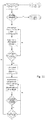
- FIG. 11 schematically illustrates a method for positioning orienting platform 124 by articulating wrist joint 98.
- robotic system 140 may be used in a master following mode to treat tissues and the like.
- the robotic system will typically halt following, and will start 131 a configuration mode which allows a user to manually configure the orienting platform in a desired orientation about fourth SUS axis 148.
- the configuration mode Once the configuration mode has been entered, the current angle O C of wrist joint 98, as sensed by the joint sensor system, is set as the desired angle ⁇ D in step 133. If a cannula is mounted to any of the manipulators supported by platform 124, the system may apply the brake to the wrist joint and exit the configuration mode so as to inhibit manual movement of the wrist joint via step 135.
- E ⁇ ⁇ ⁇ D
- the processor may halt servoing of the wrist joint to counteract articulation of the joint.
- there may be a time element of the effort threshold to overcome the servoing, such as by halting servoing in response to a torque that exceeds a threshold for a time that exceeds a threshold.
- a joint sensor between the orienting platform and the rest of the setup structure system provides a signal used to estimate torque applied to the orienting platform, and the joint displacement and servo stiffness are used to estimate a disturbance torque applied to the surgical arms and/or setup joints.
- the error signal may be filtered so as to make the system more sensitive to transient pushes than slow or steady-state signals. Such error filtering may make the trigger more sensitive while limiting false triggers when the setup structure is on a sloped surface.
- drive signals may still be sent to the wrist motor.
- friction compensation, gravity compensation, momentum compensation, and or the like may be provided 143 by applying appropriate drive signals during manual movement of the platform.
- Exemplary compensation drive systems are more fully described in US Patent Publication 2009/0326557 in the name of Neimeyer and entitled “Friction Compensation in a Minimally Invasive Surgical Apparatus," in US Patent Publication 2011/0009880 in the name of Prisco et al. and entitled “Control System for Reducing Internally Generated Frictional and Inertial Resistance to Manual Positioning of a Surgical Manipulator,” and the like.
- the system may employ joint range of motion limits alone or in addition to the drive signals when servoing is halted. Such range of motion limits may respond similar to servoing when a user pushes beyond a range motion limit except they are one sided.
- the processor may, in response, re-set the desired joint angle and re-initiate servoing (or braking) so as to inhibit movement from that joint position.
- the processor may not re-engage the servo until the articulation speed remains below a threshold for a desired dwell period.
Landscapes
- Health & Medical Sciences (AREA)
- Engineering & Computer Science (AREA)
- Life Sciences & Earth Sciences (AREA)
- Surgery (AREA)
- Robotics (AREA)
- Medical Informatics (AREA)
- Biomedical Technology (AREA)
- Heart & Thoracic Surgery (AREA)
- Nuclear Medicine, Radiotherapy & Molecular Imaging (AREA)
- Molecular Biology (AREA)
- Animal Behavior & Ethology (AREA)
- General Health & Medical Sciences (AREA)
- Public Health (AREA)
- Veterinary Medicine (AREA)
- Mechanical Engineering (AREA)
- Oral & Maxillofacial Surgery (AREA)
- Pathology (AREA)
- Manipulator (AREA)
Abstract
Description
- Minimally invasive medical techniques are intended to reduce the amount of extraneous tissue that is damaged during diagnostic or surgical procedures, thereby reducing patient recovery time, discomfort, and deleterious side effects. One effect of minimally invasive surgery, for example, is reduced post-operative hospital recovery times. Because the average hospital stay for a standard surgery is typically significantly longer than the average stay for an analogous minimally invasive surgery, increased use of minimally invasive techniques could save millions of dollars in hospital costs each year. While many of the surgeries performed each year in the United States could potentially be performed in a minimally invasive manner, only a portion of the current surgeries use these advantageous techniques due to limitations in minimally invasive surgical instruments and the additional surgical training involved in mastering them.
- Minimally invasive robotic surgical or telesurgical systems have been developed to increase a surgeon's dexterity and avoid some of the limitations on traditional minimally invasive techniques. In telesurgery, the surgeon uses some form of remote control (e.g., a servomechanism or the like) to manipulate surgical instrument movements, rather than directly holding and moving the instruments by hand. In telesurgery systems, the surgeon can be provided with an image of the surgical site at a surgical workstation. While viewing a two or three dimensional image of the surgical site on a display, the surgeon performs the surgical procedures on the patient by manipulating master control devices, which in turn control motion of the servo-mechanically operated instruments.
- The servomechanism used for telesurgery will often accept input from two master controllers (one for each of the surgeon's hands) and may include two or more robotic arms on each of which a surgical instrument is mounted. Operative communication between master controllers and associated robotic arm and instrument assemblies is typically achieved through a control system. The control system typically includes at least one processor that relays input commands from the master controllers to the associated robotic arm and instrument assemblies and back from the instrument and arm assemblies to the associated master controllers in the case of, for example, force feedback or the like. One example of a robotic surgical system is the DA VINCI® system available from Intuitive Surgical, Inc. of Sunnyvale, Calif.
- A variety of structural arrangements can be used to support the surgical instrument at the surgical site during robotic surgery. The driven linkage or "slave" is often called a robotic surgical manipulator, and exemplary linkage arrangements for use as a robotic surgical manipulator during minimally invasive robotic surgery are described in
U.S. Pat. Nos. 7,594,912 ;6,758,843 ;6,246,200 ; and5,800,423 ; the full disclosures of which are incorporated herein by reference. These linkages often make use of a parallelogram arrangement to hold an instrument having a shaft. Such a manipulator structure can constrain movement of the instrument so that the instrument pivots about a remote center of manipulation positioned in space along the length of the rigid shaft. By aligning the remote center of manipulation with the incision point to the internal surgical site (for example, with a trocar or cannula at an abdominal wall during laparoscopic surgery), an end effector of the surgical instrument can be positioned safely by moving the proximal end of the shaft using the manipulator linkage without imposing potentially dangerous forces against the abdominal wall. Alternative manipulator structures are described, for example, inU.S. Pat. Nos. 7,763,015 ;6,702,805 ;6,676,669 ;5,855,583 ;5,808,665 ;5,445,166 ; and5,184,601 ; the full disclosures of which are incorporated herein by reference. - A variety of structural arrangements can also be used to support and position the robotic surgical manipulator and the surgical instrument at the surgical site during robotic surgery. Supporting linkage mechanisms, sometimes referred to as set-up joints, or set-up joint arms, are often used to position and align each manipulator with the respective incision point in a patient's body. The supporting linkage mechanism facilitates the alignment of a surgical manipulator with a desired surgical incision point and targeted anatomy. Exemplary supporting linkage mechanisms are described in
U.S. Pat. Nos. 6,246,200 and6,788,018 , the full disclosures of which are incorporated herein by reference. - While the new telesurgical systems and devices have proven highly effective and advantageous, still further improvements are desirable. In general, improved minimally invasive robotic surgery systems are desirable. It would be particularly beneficial if these improved technologies enhanced the efficiency and ease of use of robotic surgical systems. For example, it would be particularly beneficial to increase maneuverability, improve space utilization in an operating room, provide a faster and easier set-up, inhibit collisions between robotic devices during use, and/or reduce the mechanical complexity and size of these new surgical systems.
- The following presents a simplified summary of some embodiments of the invention in order to provide a basic understanding of the invention. This summary is not an extensive overview of the invention. It is not intended to identify key/critical elements of the invention or to delineate the scope of the invention. Its sole purpose is to present some embodiments of the invention in a simplified form as a prelude to the more detailed description that is presented later.
- The present invention generally provides improved robotic and/or surgical devices, systems, and methods. Kinematic linkage structures and associated control systems described herein are particularly beneficial in helping system users to arrange the robotic structure in preparation for use, including in preparation for a surgical procedure on a particular patient. Exemplary robotic surgical systems described herein may have one or more kinematic linkage subsystems that are configured to help align a manipulator structure with the surgical work site. The joints of these set-up systems may be actively driven, passive (so that they are manually articulated and then locked into the desired configuration while the manipulator is used therapeutically), or a mix of both. Embodiments of the robotic systems described herein may employ a set-up mode in which one or more joints are initially held static by a brake or joint drive system. Inadvertent articulation is limited by the brake or drive system, but the user can manually articulate the joint(s) by manually pushing against the linkage with a force, torque, or the like that exceeds a manual articulation threshold of the joint(s). Once the joint(s) begin to move, a processor may facilitate articulation with less user effort by modifying the signals transmitted to the brake or drive system. When the user arrives at a desired configuration, the system may sense that the user has completed the reconfiguration from a velocity of the joint(s) below a threshold, optionally for a desired dwell time. The system may then again inhibit inadvertent articulation of the joint(s. The dwell time can help avoid locking the linkage when reversing directions, and the system can provide a "detent" like manual articulation that is not limited to mechanically pre-defined detent joint configurations. Embodiments of the invention provide a user interface is intuitive, and can be particularly well-suited for manual movement of a platform supporting a plurality of surgical manipulators in a robotic surgical system or the like without having to add additional input devices.
- In a first aspect, the invention provides a method for configuring a robotic system. The method comprises inhibiting manual articulation of a linkage of the system from a first pose in response to a first manual effort against the linkage being below a desired articulation threshold. A manual movement of the linkage from the first pose toward a second pose is facilitated in response to a second manual effort to articulate the linkage exceeding the desired articulation threshold. The second pose is determined in response to the manual movement of the linkage. Manual movement of the linkage from the second pose is inhibited.
- Thus, in a first aspect, a method for configuring a robotic system is provided. The method includes inhibiting manual articulation of a linkage of the system from a first pose in response to a first manual effort against the linkage, facilitating a manual movement of the linkage from the first pose toward a second pose, determining the second pose in response to the manual movement of the linkage, and inhibiting manual movement of the linkage from the second pose. The inhibiting step is in response to a first manual effort against the linkage that is below a desired articulation threshold. The facilitating step is in response to a second manual effort against the linkage that exceeds the desired articulation threshold.
- In other exemplary embodiments, a joint sensor may sense a first torque of the first manual effort applied to a joint and a processor may inhibit the manual articulation by determining drive signals configured to induce a counteracting torque to the linkage opposing the first torque so as to urge the linkage back toward the first pose. In further embodiments, the joint sensor may also sense the second torque of the second manual effort applied to the joint and the processor may be configured to determine that the second effort exceeds the desired articulation threshold. For example, in some embodiments the articulation threshold may be a torque threshold and the processor may determine that the second effort exceeds the desired articulation threshold by determining that the second torque exceeds the threshold torque. In response to a second effort exceeding the desired articulation threshold, the processor may alter the drive signals so as to decrease the counteracting torque so that the first torque is sufficient to manually move the manipulator.
- In some embodiments of the method, a processor may alter drive signals in response to the second effort exceeding the desired articulation threshold by adding a friction compensation component to the drive signals so as to mitigate friction of the linkage for the manual movement toward the second pose.
- In other embodiments, the second pose may be determined by determining that a velocity of the manual movement is below a threshold velocity. Additionally, the second pose may also be determined by determining that the velocity of the manual movement remains below the threshold velocity for a threshold dwell time so as to facilitate reversing a direction of the movement without inhibiting manual movement.
- In further embodiments, the method for configuring a robotic system includes driving the linkage in the second pose with drive signals so as to inhibit manual movement of the linkage from the second pose in response to a third manual effort against the manipulator being below the desired articulation threshold.
- The above exemplary methods may be used to configure a surgical robotic system. For example, the linkage may be a set-up structure having a proximal base and a platform with the joint disposed therebetween. The platform may support a plurality of surgical manipulators, where each manipulator may be an instrument holder configured to releasably receive a surgical instrument. The manual movement may be a movement that alters positions of the plurality of manipulators relative to a surgical site. In another example, the linkage may be included in a surgical manipulator having a holder for releasably receiving a surgical instrument. The surgical manipulator may also include a cannula interface configured for releasably receiving a cannula. The manipulator may be further configured to pivotably move a shaft of the instrument within an aperture adjacent the cannula so as to manipulate an end effector of the instrument within a minimally invasive surgical aperture. The configuration method may further include inhibiting manual articulation of the joint with manual effort exceeding the desired articulation threshold in response to the mounting of the cannula to the cannula interface.
- In another aspect, a robotic system is provided. The robotic system includes a linkage having a joint, a drive or brake system coupled to the linkage, and a processor coupled with the drive or brake system. The processor may be configured to transmit signals to the drive or brake system so as to inhibit manual articulation of the linkage from a first pose in response to a first manual effort against the linkage being below a desired articulation threshold. The processor may alter the signals in response to a second manual effort to articulate the linkage exceeding the desired articulation threshold. The altered signals may be configured to facilitate a manual movement of the linkage from the first pose toward a second pose. The processor may also determine the second pose in response to the manual movement of the linkage and may transmit the signals to the drive system so as to inhibit manual movement of the linkage from the second pose.
- In additional exemplary embodiments, the robotic system further includes a joint sensor coupled to the joint. The joint sensor may be configured to sense a first torque of the first manual effort applied to the joint. The processor may be configured to determine the signals so as to apply a counteracting torque to the linkage opposing the first torque and urge the linkage back toward the first pose. In particular embodiments, a drive or brake system may include a drive system. Further, the joint sensor may be configured so as to transmit to the processor a second torque of the second manual effort applied to the joint. The processor may be further configured to determine if the second effort exceeds the desired articulation threshold using the second torque. For example, the processor may be configured to determine that the second effort exceeds the desired articulation threshold by determining whether the second torque exceeds a threshold torque. In response to a second effort exceeding the desired articulation threshold, the processor may alter the drive signals so as to decrease the counteracting torque so that the first torque is sufficient to manually move the manipulator.
- In some embodiments, the signals of the robotic system may include drive signals and the processor may be configured to alter the drive signals in response to the second effort exceeding the desired articulation threshold by adding a friction compensation component to the drive signals so as to mitigate friction of the linkage for the manual movement toward the second pose.
- The processor may be configured to determine a second pose in response to a velocity of the manual movement being below a threshold velocity. The processor may be further configured to determine the second pose by determining that the velocity of the manual movement is below the threshold velocity for a threshold dwell time so as to facilitate a reversal of a direction of the manual movement without inhibiting the manual movement. The processor may also be configured to inhibit manual movement of the linkage from the second pose in response to a third manual effort against the manipulator being below the desired articulation threshold.
- The above exemplary system may be a surgical robotic system. For example, the linkage may be a set-up structure having a proximal base and a platform with the joint disposed therebetween. The platform may support a plurality of surgical manipulators, where each manipulator may be an instrument holder configured to releasably receive a surgical instrument. The manual movement may be a movement that alters positions of the plurality of manipulators relative to a surgical site. In another example, the linkage may be included in a surgical manipulator having a holder for releasably receiving a surgical instrument. The surgical manipulator may also include a cannula interface configured for releasably receiving a cannula. The manipulator may be further configured to pivotably move a shaft of the instrument within an aperture adjacent the cannula so as to manipulate an end effector of the instrument within a minimally invasive surgical aperture. The system may further include inhibiting manual articulation of the joint with manual effort exceeding the desired articulation threshold in response to the mounting of the cannula to the cannula interface.
- In an additional aspect, a robotic surgical system is provided. The robotic surgical system includes a linkage having a joint, a drive system coupled to the linkage, a torque sensor system coupled to the joint, and a processor coupling the torque sensor with the drive system. The joint may be disposed between a proximal base and an instrument holder. The instrument holder may be configured for releasably supporting a surgical instrument. The processor is configured to transmit drive signals to the drive system so as to inhibit manual articulation of the joint from a first configuration in response to a sensed torque being below a desired articulation threshold. In response to a sensed torque exceeding the desired articulation threshold, the processor may alter the drive signals to facilitate a manual movement of the joint from the first configuration toward a second configuration using a movement torque lower than the articulation threshold. In response to a velocity of the manual movement being below a threshold velocity, the processor may determine the second configuration. The processor may also be configured to transmit drive signals to the drive system so as to inhibit manual movement of the linkage from the second pose in response to a sensed torque being below a desired articulation threshold.
- In another aspect, a method of configuring a robotic system is provided. The method includes driving a robotic assembly during manual efforts to move a linkage of the assembly so as to simulate a first and second detent of the linkage at first and second linkage poses. The method also includes determining the second pose in response to a manual movement of the linkage to the second pose.
- For a fuller understanding of the nature and advantages of the present invention, reference should be made to the ensuing detailed description and accompanying drawings. Other aspects, objects and advantages of the invention will be apparent from the drawings and detailed description that follows.
-
-
FIG. 1 is a plan view of a minimally invasive robotic surgery system being used to perform a surgery, in accordance with many embodiments. -
FIG. 2 is a perspective view of a surgeon's control console for a robotic surgery system, in accordance with many embodiments. -
FIG. 3 is a perspective view of a robotic surgery system electronics cart, in accordance with many embodiments. -
FIG. 4 diagrammatically illustrates a robotic surgery system, in accordance with many embodiments. -
FIG. 5A is a partial view of a patient side cart (surgical robot) of a robotic surgery system, in accordance with many embodiments. -
FIG. 5B is a front view of a robotic surgery tool, in accordance with many embodiments. -
FIG. 6 is a perspective schematic representation of a robotic surgery system, in accordance with many embodiments. -
FIG. 7 is a perspective schematic representation of another robotic surgery system, in accordance with many embodiments. -
FIG. 8 shows a robotic surgery system, in accordance with many embodiments, in conformance with the schematic representation ofFIG. 7 . -
FIG. 9 illustrates rotational orientation limits of set-up linkages relative to an orienting platform of the robotic surgery system ofFIG. 8 . -
FIG. 10 shows a center of gravity diagram associated with a rotational limit of the boom assembly for a robotic surgery system, in accordance with many embodiments. -
FIG. 11 is a flow chart schematically illustrating a method for preparing a robotic surgical system for surgery. - In the following description, various embodiments of the present invention will be described. For purposes of explanation, specific configurations and details are set forth in order to provide a thorough understanding of the embodiments. However, it will also be apparent to one skilled in the art that the present invention may be practiced without the specific details. Furthermore, well-known features may be omitted or simplified in order not to obscure the embodiment being described.
- The kinematic linkage structures and control systems described herein are particularly beneficial in helping system users to arrange the robotic structure of a procedure on a particular patient. Along with actively driven manipulators used to interact with tissues and the like during treatment, robotic surgical systems may have one or more kinematic linkage systems that are configured to support and help align the manipulator structure with the surgical work site. These set-up systems may be actively driven or may be passive, so that they are manually articulated and then locked into the desired configuration while the manipulator is used therapeutically. The passive set-up kinematic systems may have advantages in size, weight, complexity, and cost. Unfortunately, a plurality of manipulators may be used to treat tissues of each patient, the manipulators may each independently benefit from accurate positioning so as to allow the instrument supported by that instrument to have the desired motion throughout the workspace, and minor changes in the relative locations of adjacent manipulators may have significant impact on the interactions between manipulators (with poorly positioned manipulators potentially colliding or having their range and/or ease of motion significantly reduced). Hence, the challenges of quickly arranging the robotic system in preparation for surgery can be significant.
- One option is to mount multiple manipulators to a single platform, with the manipulator-supporting platform sometimes being referred to as an orienting platform. The orienting platform can be supported by an actively driven support linkage (sometimes referred to herein as a set-up structure, and typically having a set-up structure linkage, etc.) The system may also provide and control motorized axes of the robotic set-up structure supporting the orienting platform with some kind of joystick or set of buttons that would allow the user to actively drive those axes as desired in an independent fashion. This approach, while useful in some situations, may suffer from some disadvantages. In particular, it may be difficult to locate a drive button for all the elements of a complex system so that each is accessible to users approaching the system in all its potential configurations. While individual clutch buttons might also be used to release the brake or drive system, the possibility of confusion may remain between buttons having different functions. Furthermore, both sterile and non-sterile members of a surgical team may want to articulate some joints or linkages (such as by grabbing differing locations inside or outside the sterile field). Hence a more intuitive and flexible user interface would be desirable. This is particularly true of an orienting platform for use in multi-quadrant surgery, or for a structure that supports a plurality of surgical manipulators and may pivot about an axis extending at least roughly vertically so as to orient the manipulators relative to a patient on a surgical table or other support.
- Referring now to the drawings, in which like reference numerals represent like parts throughout the several views,
FIG. 1 is a plan view illustration of a Minimally Invasive Robotic Surgical (MIRS)system 10, typically used for performing a minimally invasive diagnostic or surgical procedure on aPatient 12 who is lying down on an Operating table 14. The system can include a Surgeon'sConsole 16 for use by aSurgeon 18 during the procedure. One ormore Assistants 20 may also participate in the procedure. TheMIRS system 10 can further include a Patient Side Cart 22 (surgical robot) and anElectronics Cart 24. ThePatient Side Cart 22 can manipulate at least one removably coupled tool assembly 26 (hereinafter simply referred to as a "tool") through a minimally invasive incision in the body of thePatient 12 while theSurgeon 18 views the surgical site through theConsole 16. An image of the surgical site can be obtained by anendoscope 28, such as a stereoscopic endoscope, which can be manipulated by thePatient Side Cart 22 to orient theendoscope 28. TheElectronics Cart 24 can be used to process the images of the surgical site for subsequent display to theSurgeon 18 through the Surgeon'sConsole 16. The number ofsurgical tools 26 used at one time will generally depend on the diagnostic or surgical procedure and the space constraints within the operating room among other factors. If it is necessary to change one or more of thetools 26 being used during a procedure, anAssistant 20 may remove thetool 26 from thePatient Side Cart 22, and replace it with anothertool 26 from atray 30 in the operating room. -
FIG. 2 is a perspective view of the Surgeon'sConsole 16. The Surgeon'sConsole 16 includes aleft eye display 32 and aright eye display 34 for presenting theSurgeon 18 with a coordinated stereo view of the surgical site that enables depth perception. TheConsole 16 further includes one or moreinput control devices 36, which in turn cause the Patient Side Cart 22 (shown inFIG. 1 ) to manipulate one or more tools. Theinput control devices 36 can provide the same degrees of freedom as their associated tools 26 (shown inFIG. 1 ) to provide the Surgeon with telepresence, or the perception that theinput control devices 36 are integral with thetools 26 so that the Surgeon has a strong sense of directly controlling thetools 26. To this end, position, force, and tactile feedback sensors (not shown) may be employed to transmit position, force, and tactile sensations from thetools 26 back to the Surgeon's hands through theinput control devices 36. - The Surgeon's
Console 16 is usually located in the same room as the patient so that the Surgeon may directly monitor the procedure, be physically present if necessary, and speak to an Assistant directly rather than over the telephone or other communication medium. However, the Surgeon can be located in a different room, a completely different building, or other remote location from the Patient allowing for remote surgical procedures. -
FIG. 3 is a perspective view of theElectronics Cart 24. TheElectronics Cart 24 can be coupled with theendoscope 28 and can include a processor to process captured images for subsequent display, such as to a Surgeon on the Surgeon's Console, or on another suitable display located locally and/or remotely. For example, where a stereoscopic endoscope is used, theElectronics Cart 24 can process the captured images to present the Surgeon with coordinated stereo images of the surgical site. Such coordination can include alignment between the opposing images and can include adjusting the stereo working distance of the stereoscopic endoscope. As another example, image processing can include the use of previously determined camera calibration parameters to compensate for imaging errors of the image capture device, such as optical aberrations. -
FIG. 4 diagrammatically illustrates a robotic surgery system 50 (such asMIRS system 10 ofFIG. 1 ). As discussed above, a Surgeon's Console 52 (such as Surgeon'sConsole 16 inFIG. 1 ) can be used by a Surgeon to control a Patient Side Cart (Surgical Robot) 54 (such asPatent Side Cart 22 inFIG. 1 ) during a minimally invasive procedure. ThePatient Side Cart 54 can use an imaging device, such as a stereoscopic endoscope, to capture images of the procedure site and output the captured images to an Electronics Cart 56 (such as theElectronics Cart 24 inFIG. 1 ). As discussed above, theElectronics Cart 56 can process the captured images in a variety of ways prior to any subsequent display. For example, theElectronics Cart 56 can overlay the captured images with a virtual control interface prior to displaying the combined images to the Surgeon via the Surgeon'sConsole 52. ThePatient Side Cart 54 can output the captured images for processing outside theElectronics Cart 56. For example, thePatient Side Cart 54 can output the captured images to aprocessor 58, which can be used to process the captured images. The images can also be processed by a combination theElectronics Cart 56 and theprocessor 58, which can be coupled together to process the captured images jointly, sequentially, and/or combinations thereof. One or moreseparate displays 60 can also be coupled with theprocessor 58 and/or theElectronics Cart 56 for local and/or remote display of images, such as images of the procedure site, or other related images. -
Processor 58 will typically include a combination of hardware and software, with the software comprising tangible media embodying computer readable code instructions for performing the method steps of the control functionally described herein. The hardware typically includes one or more data processing boards, which may be co-located but will often have components distributed among the robotic structures described herein. The software will often comprise a nonvolatile media, and could also comprise a monolithic code but will more typically comprise a number of subroutines, optionally running in any of a wide variety of distributed data processing architectures. -
FIGS. 5A and5B show aPatient Side Cart 22 and asurgical tool 62, respectively. Thesurgical tool 62 is an example of thesurgical tools 26. ThePatient Side Cart 22 shown provides for the manipulation of threesurgical tools 26 and animaging device 28, such as a stereoscopic endoscope used for the capture of images of the site of the procedure. Manipulation is provided by robotic mechanisms having a number of robotic joints. Theimaging device 28 and thesurgical tools 26 can be positioned and manipulated through incisions in the patient so that a kinematic remote center is maintained at the incision to minimize the size of the incision. Images of the surgical site can include images of the distal ends of thesurgical tools 26 when they are positioned within the field-of-view of theimaging device 28. -
Surgical tools 26 are inserted into the patient by inserting a tubular cannula 64 through a minimally invasive access aperture such as an incision, natural orifice, percutaneous penetration, or the like. Cannula 64 is mounted to the robotic manipulator arm and the shaft ofsurgical tool 26 passes through the lumen of the cannula. The manipulator arm may transmit signals indicating that the cannula has been mounted thereon. -
FIG. 6 is a perspective schematic representation of arobotic surgery system 70, in accordance with many embodiments. Thesurgery system 70 includes a mountingbase 72, asupport linkage 74, an orientingplatform 76, a plurality of outer set-up linkages 78 (two shown), a plurality of inner set-up linkages 80 (two shown), and a plurality of surgical instrument manipulators 82. Each of themanipulators 82 is operable to selectively articulate a surgical instrument mounted to themanipulator 82 and insertable into a patient along an insertion axis. Each of themanipulators 82 is attached to and supported by one of the set-uplinkages linkages 78 is rotationally coupled to and supported by the orientingplatform 76 by a first set-uplinkage joint 84. Each of the inner set-uplinkages 80 is fixedly attached to and supported by the orientingplatform 76. The orientingplatform 76 is rotationally coupled to and supported by thesupport linkage 74. And thesupport linkage 74 is fixedly attached to and supported by the mountingbase 72. - In many embodiments, the mounting
base 72 is a movable and floor supported, thereby enabling selective repositioning of theoverall surgery system 70, for example, within an operating room. The mountingbase 72 can include a steerable wheel assembly and/or any other suitable support features that provide for both selective repositioning as well as selectively preventing movement of the mountingbase 72 from a selected position. The mountingbase 72 can also have other suitable configurations, for example, a ceiling mount, fixed floor/pedestal mount, a wall mount, or an interface configured for being supported by any other suitable mounting surface. - The
support linkage 74 is operable to selectively position and/or orient the orientingplatform 76 relative to the mountingbase 72. Thesupport linkage 74 includes acolumn base 86, atranslatable column member 88, ashoulder joint 90, aboom base member 92, a boomfirst stage member 94, a boomsecond stage member 96, and a wrist joint 98. Thecolumn base 86 is fixedly attached to the mountingbase 72. Thetranslatable column member 88 is slideably coupled to thecolumn base 86 for translation relative tocolumn base 86. In many embodiments, thetranslatable column member 88 translates relative to thecolumn base 86 along a vertically oriented axis. Theboom base member 92 is rotationally coupled to thetranslatable column member 88 by theshoulder joint 90. Theshoulder joint 90 is operable to selectively orient theboom base member 92 in a horizontal plane relative to thetranslatable column member 88, which has a fixed angular orientation relative to thecolumn base 86 and the mountingbase 72. The boomfirst stage member 94 is selectively translatable relative to theboom base member 92 in a horizontal direction, which in many embodiments is aligned with both theboom base member 92 and the boomfirst stage member 94. The boomsecond stage member 96 is likewise selectively translatable relative to the boomfirst stage member 94 in a horizontal direction, which in many embodiments is aligned with the boomfirst stage member 94 and the boomsecond stage member 96. Accordingly, thesupport linkage 74 is operable to selectively set the distance between theshoulder joint 90 and the distal end of the boomsecond stage member 96. The wrist joint 98 rotationally couples the distal end of the boomsecond stage member 96 to the orientingplatform 76. The wrist joint 98 is operable to selectively set the angular orientation of the orientingplatform 76 relative to the mountingbase 72. - Each of the set-up
linkages manipulator 82 relative to the orientingplatform 76. Each of the set-uplinkages linkage base link 100, a set-uplinkage extension link 102, a set-up linkageparallelogram linkage portion 104, a set-up linkagevertical link 106, a second set-uplinkage joint 108, and amanipulator support link 110. In each of the set-uplinkage base links 100 of the outer set-uplinkages 78 can be selectively oriented relative to the orientingplatform 76 via the operation of the a first set-uplinkage joint 84. In the embodiment shown, each of the set-uplinkage base links 100 of the inner set-uplinkages 80 is fixedly attached to the orientingplatform 76. Each of the inner set-uplinkages 80 can also be rotationally attached to the orientingplatform 76 similar to the outer set-up linkages via an additional first set-up linkage joints 84. Each of the set-up linkage extension links 102 is translatable relative to the associated set-uplinkage base link 100 in a horizontal direction, which in many embodiments is aligned with the associated set-up linkage base link and the set-uplinkage extension link 102. Each of the set-up linkageparallelogram linkage portions 104 configured and operable to selectively translate the set-up linkagevertical link 106 in a vertical direction while keeping the set-up linkagevertical link 106 vertically oriented. In example embodiments, each of the set-up linkageparallelogram linkage portions 104 includes a first parallelogram joint 112, acoupling link 114, and asecond parallelogram 116. The first parallelogram joint 112 rotationally couples thecoupling link 114 to the set-uplinkage extension link 102. The second parallelogram joint 116 rotationally couples the set-up linkagevertical link 106 to thecoupling link 114. The first parallelogram joint 112 is rotationally tied to the second parallelogram joint 116 such that rotation of thecoupling link 114 relative to the set-uplinkage extension link 102 is matched by a counteracting rotation of the set-up linkagevertical link 106 relative to thecoupling link 114 so as to maintain the set-up linkagevertical link 106 vertically oriented while the set-up linkagevertical link 106 is selectively translated vertically. The second set-uplinkage joint 108 is operable to selectively orient themanipulator support link 110 relative to the set-up linkagevertical link 106, thereby selectively orienting the associated attachedmanipulator 82 relative to the set-up linkagevertical link 106. -
FIG. 7 is a perspective schematic representation of arobotic surgery system 120, in accordance with many embodiments. Because thesurgery system 120 includes components similar to components of thesurgery system 70 ofFIG. 6 , the same reference numbers are used for similar components and the corresponding description of the similar components set forth above is applicable to thesurgery system 120 and is omitted here to avoid repetition. Thesurgery system 120 includes the mountingbase 72, asupport linkage 122, anorienting platform 124, a plurality of set-up linkages 126 (four shown), and a plurality of the surgical instrument manipulators 82. Each of themanipulators 82 is operable to selectively articulate a surgical instrument mounted to themanipulator 82 and insertable into a patient along an insertion axis. Each of themanipulators 82 is attached to and supported by one of the set-uplinkages 126. Each of the set-uplinkages 126 is rotationally coupled to and supported by the orientingplatform 124 by the first set-uplinkage joint 84. The orientingplatform 124 is rotationally coupled to and supported by thesupport linkage 122. And thesupport linkage 122 is fixedly attached to and supported by the mountingbase 72. - The
support linkage 122 is operable to selectively position and/or orient theorienting platform 124 relative to the mountingbase 72. Thesupport linkage 122 includes thecolumn base 86, thetranslatable column member 88, theshoulder joint 90, theboom base member 92, the boomfirst stage member 94, and the wrist joint 98. Thesupport linkage 122 is operable to selectively set the distance between theshoulder joint 90 and the distal end of the boomfirst stage member 94. The wrist joint 98 rotationally couples the distal end of the boomfirst stage member 94 to theorienting platform 124. The wrist joint 98 is operable to selectively set the angular orientation of theorienting platform 124 relative to the mountingbase 72. - Each of the set-up
linkages 126 is operable to selectively position and/or orient the associatedmanipulator 82 relative to theorienting platform 124. Each of the set-uplinkages 126 includes the set-uplinkage base link 100, the set-uplinkage extension link 102, the set-up linkagevertical link 106, the second set-uplinkage joint 108, a tornadomechanism support link 128, and atornado mechanism 130. Each of the set-uplinkage base links 100 of the set-uplinkages 126 can be selectively oriented relative to theorienting platform 124 via the operation of the associated first set-uplinkage joint 84. Each of the set-up linkagevertical links 106 is selectively translatable in a vertical direction relative to the associated set-uplinkage extension link 102. The second set-uplinkage joint 108 is operable to selectively orient the tornadomechanism support link 128 relative to the set-up linkagevertical link 106 - Each of the
tornado mechanisms 130 includes a tornado joint 132, acoupling link 134, and amanipulator support 136. Thecoupling link 134 fixedly couples themanipulator support 136 to the tornado joint 132. The tornado joint 130 is operable to rotate themanipulator support 136 relative to the tornadomechanism support link 128 around atornado axis 136. Thetornado mechanism 128 is configured to position and orient themanipulator support 134 such that the remote center of manipulation (RC) of themanipulator 82 is intersected by thetornado axis 136. Accordingly, operation of the tornado joint 132 can be used to reorient the associatedmanipulator 82 relative to the patient without moving the associated remote center of manipulation (RC) relative to the patient. -
FIG. 8 is a simplified representation of arobotic surgery system 140, in accordance with many embodiments, in conformance with the schematic representation of therobotic surgery system 120 ofFIG. 7 . Because thesurgery system 140 conforms to therobotic surgery system 120 ofFIG. 7 , the same reference numbers are used for analogous components and the corresponding description of the analogous components set forth above is applicable to thesurgery system 140 and is omitted here to avoid repetition. - The
support linkage 122 is configured to selectively position and orient theorienting platform 124 relative to the mountingbase 72 via relative movement between links of thesupport linkage 122 along multiple set-up structure axes. Thetranslatable column member 88 is selectively repositionable relative to thecolumn base 86 along a first set-up structure (SUS)axis 142, which is vertically oriented in many embodiments. Theshoulder joint 90 is operable to selectively orient theboom base member 92 relative to thetranslatable column member 88 around asecond SUS axis 144, which is vertically oriented in many embodiments. The boomfirst stage member 94 is selectively repositionable relative to theboom base member 92 along athird SUS axis 146, which is horizontally oriented in many embodiments. The wrist joint 98 is operable to selectively orient theorienting platform 124 relative to the boomfirst stage member 94 around afourth SUS axis 148, which is vertically oriented in many embodiments. - Each of the set-up
linkages 126 is configured to selectively position and orient the associatedmanipulator 82 relative to theorienting platform 124 via relative movement between links of the set-uplinkage 126 along multiple set-up joint (SUJ) axes. Each of the first set-up linkage joint 84 is operable to selectively orient the associated set-uplinkage base link 100 relative to theorienting platform 124 around afirst SUJ axis 150, which in many embodiments is vertically oriented. Each of the set-up linkage extension links 102 can be selectively repositioned relative to the associated set-uplinkage base link 10 along asecond SUJ axis 152, which is horizontally oriented in many embodiments. Each of the set-up linkagevertical links 106 can be selectively repositioned relative to the associated set-uplinkage extension link 102 along athird SUJ axis 154, which is vertically oriented in many embodiments. Each of the second set-uplinkage joints 108 is operable to selectively orient the tornadomechanism support link 128 relative to the set-up linkagevertical link 106 around thethird SUJ axis 154. Each of the tornado joints 132 is operable to rotate the associatedmanipulator 82 around the associatedtornado axis 138. -
FIG. 9 illustrates rotational orientation limits of the set-uplinkages 126 relative to theorienting platform 124, in accordance with many embodiments. Each of the set-uplinkages 126 is shown in a clockwise limit orientation relative to theorienting platform 124. A corresponding counter-clockwise limit orientation is represented by a mirror image ofFIG. 9 relative to a vertically-oriented mirror plane. As illustrated, each of the two inner set-uplinkages 126 can be oriented from 5 degrees from avertical reference 156 in one direction to 75 degrees from thevertical reference 156 in the opposite direction. And as illustrated, each of the two outer set-up linkages can be oriented from 15 degrees to 95 degrees from thevertical reference 156 in a corresponding direction. - In use, it will often be desirable for a surgical assistant, surgeon, technical support, or other user to configure some or all of the linkages of robotic
surgical system 140 for surgery, including the set-up structure linkage, the set-up joints, and/or each of the manipulators. Included among the task in configuring these linkages will be positioning theorienting platform 124 relative tofirst stage member 94 about verticalfourth SUS axis 148 of wrist joint 98. A joint drive motor 121 and/or brake system 123 is coupled to wrist joint 98, with one exemplary embodiment including both a drive 121 and brake 123. Additionally, a joint sensor system will typically sense an angular configuration or position of wrist joint 98. - An exemplary user interface, system, and method for manually configuring the system for use will be described herein with reference to manual articulation of orienting
platform 124 by articulation of wrist joint 98 about fourth SUSaxis 148, as schematically illustrated by arrow 127. It should be understood that alternative embodiments may be employed to articulate one or more alternative joints of the overall kinematic system, including one or more alternative joints of the set-up structure, one or more of the set-up joints, or one or more of the joints of the manipulators linkages. Use of the exemplary embodiment for articulating the motorized wrist joint embodiments may allow a user to efficiently positionmanipulators 82. The manual articulation of wrist joint 98 as described herein can improve speed and ease of use while manually dockingmanipulators 82 to their associated cannulas 64, as shown inFIG. 5B . -
FIG. 10 shows a center of gravity diagram associated with a rotational limit of a support linkage for arobotic surgery system 160, in accordance with many embodiments. With components of therobotic surgery system 160 positioned and oriented to shift the center-of-gravity 162 of therobotic surgery system 160 to a maximum extent to one side relative to asupport linkage 164 of thesurgery system 160, a shoulder joint of thesupport linkage 164 can be configured to limit rotation of thesupport structure 164 around a set-up structure (SUS) shoulder-joint axis 166 to prevent exceeding a predetermined stability limit of the mounting base. -
FIG. 11 schematically illustrates a method for positioning orientingplatform 124 by articulating wrist joint 98. As generally described above,robotic system 140 may be used in a master following mode to treat tissues and the like. The robotic system will typically halt following, and will start 131 a configuration mode which allows a user to manually configure the orienting platform in a desired orientation about fourth SUSaxis 148. Once the configuration mode has been entered, the current angle OC of wrist joint 98, as sensed by the joint sensor system, is set as the desired angle θD in step 133. If a cannula is mounted to any of the manipulators supported byplatform 124, the system may apply the brake to the wrist joint and exit the configuration mode so as to inhibit manual movement of the wrist joint via step 135. - While in the configuration mode, when the platform is not moving about the wrist joint the system processor will typically transmit signals to the joint motor associated with wrist joint 98 so as to maintain the set desired angle θD. Hence, when the system is bumped, pushed, or pulled lightly the wrist motor may urge the platform back toward the desired angle by applying a joint torque per an error E that varies with the difference between the sensed joint position and the desired joint position:

- When a user pushes or pulls on one or more of the surgical manipulators, the set-up joint linkages, or directly on the platform with an effort sufficient to exceed the desired articulation threshold the user is able to rotate the orienting platform without having to fight the servo control. Although servoing so as to counteract the user movement of the platform is halted in step 141, drive signals may still be sent to the wrist motor. For example, friction compensation, gravity compensation, momentum compensation, and or the like may be provided 143 by applying appropriate drive signals during manual movement of the platform. Exemplary compensation drive systems are more fully described in
US Patent Publication 2009/0326557 in the name of Neimeyer and entitled "Friction Compensation in a Minimally Invasive Surgical Apparatus," inUS Patent Publication 2011/0009880 in the name of Prisco et al. and entitled "Control System for Reducing Internally Generated Frictional and Inertial Resistance to Manual Positioning of a Surgical Manipulator," and the like. In some embodiments, the system may employ joint range of motion limits alone or in addition to the drive signals when servoing is halted. Such range of motion limits may respond similar to servoing when a user pushes beyond a range motion limit except they are one sided. - Once the user has manually articulated to wrist near the desired orientation, the user will tend to slow the platform down and upon reaching the desired configuration will halt movement of the platform. The system takes advantage of this, and as the joint sensor indicates that movement of the platform falls below a desired threshold of zero the processor may, in response, re-set the desired joint angle and re-initiate servoing (or braking) so as to inhibit movement from that joint position. As the user may want to reverse direction of the manual joint articulation to correct any overshoot, the processor may not re-engage the servo until the articulation speed remains below a threshold for a desired dwell period.
- Other variations are within the spirit of the present invention. Thus, while the invention is susceptible to various modifications and alternative constructions, certain illustrated embodiments thereof are shown in the drawings and have been described above in detail. It should be understood, however, that there is no intention to limit the invention to the specific form or forms disclosed, but on the contrary, the intention is to cover all modifications, alternative constructions, and equivalents falling within the spirit and scope of the invention, as defined in the appended claims.
- The use of the terms "a" and "an" and "the" and similar referents in the context of describing the invention (especially in the context of the following claims) are to be construed to cover both the singular and the plural, unless otherwise indicated herein or clearly contradicted by context. The terms "comprising," "having," "including," and "containing" are to be construed as open-ended terms (i.e., meaning "including, but not limited to,") unless otherwise noted. The term "connected" is to be construed as partly or wholly contained within, attached to, or joined together, even if there is something intervening. Recitation of ranges of values herein are merely intended to serve as a shorthand method of referring individually to each separate value falling within the range, unless otherwise indicated herein, and each separate value is incorporated into the specification as if it were individually recited herein. All methods described herein can be performed in any suitable order unless otherwise indicated herein or otherwise clearly contradicted by context. The use of any and all examples, or exemplary language (e.g., "such as") provided herein, is intended merely to better illuminate embodiments of the invention and does not pose a limitation on the scope of the invention unless otherwise claimed. No language in the specification should be construed as indicating any non-claimed element as essential to the practice of the invention.
- Preferred embodiments of this invention are described herein, including the best mode known to the inventors for carrying out the invention. Variations of those preferred embodiments may become apparent to those of ordinary skill in the art upon reading the foregoing description. The inventors expect skilled artisans to employ such variations as appropriate, and the inventors intend for the invention to be practiced otherwise than as specifically described herein. Accordingly, this invention includes all modifications and equivalents of the subject matter recited in the claims appended hereto as permitted by applicable law. Moreover, any combination of the above-described elements in all possible variations thereof is encompassed by the invention unless otherwise indicated herein or otherwise clearly contradicted by context.
- All references, including publications, patent applications, and patents, cited herein are hereby incorporated by reference to the same extent as if each reference were individually and specifically indicated to be incorporated by reference and were set forth in its entirety herein.
- The present application also includes the following numbered clauses:
- 1. A method for configuring a robotic system, the method comprising:
- inhibiting manual articulation of a linkage of the system from a first pose in response to a first manual effort against the linkage being below a desired articulation threshold;
- facilitating a manual movement of the linkage from the first pose toward a second pose, in response to a second manual effort to articulate the linkage exceeding the desired articulation threshold;
- determining the second pose in response to the manual movement of the linkage; and
- inhibiting manual movement of the linkage from the second pose.
- 2. The method of clause 1, wherein a joint sensor senses a first torque of the first manual effort applied to a joint, and wherein inhibiting the manual articulation comprises, with a processor, determining drive signals configured to induce a counteracting torque to the linkage opposing the first torque so as to urge the linkage back toward the first pose.
- 3. The method of clause 2, wherein:
- the joint sensor senses a second torque of the second manual effort applied to the joint, and
- the processor of the system determines the second effort exceeds the desired articulation threshold using the second torque, and in response, alters the drive signals so as to decrease the counteracting torque so that the first torque is sufficient to manually move the manipulator.
- 4. The method of clause 3, wherein the processor determines the second effort exceeds the desired articulation threshold in response to the second torque exceeding a threshold torque.
- 5. The method of clause 1, wherein a processor of the system alters drive signals in response to the second effort exceeding the desired articulation threshold by adding a friction compensation component to the drive signals so as to mitigate friction of the linkage for the manual movement toward the second pose.
- 6. The method of clause 1, wherein determining the second pose comprises determining a velocity of the manual movement is below a threshold velocity.
- 7. The method of
clause 6, wherein determining the second pose further comprises determining the velocity of the manual movement remains below the threshold velocity for a threshold dwell time so as to facilitate reversing a direction of the movement without inhibiting manual movement. - 8. The method of clause 1, further comprising driving the linkage in the second pose with drive signals so as to inhibit manual movement of the linkage from the second pose in response to a third manual effort against the manipulator being below the desired articulation threshold.
- 9. The method of clause 1, wherein the robotic system comprises a surgical robotic system, wherein the linkage comprises a set-up structure having a proximal base and a platform with the joint disposed therebetween, wherein the platform supports a plurality of surgical manipulators, each manipulator comprising an instrument holder configured for releasably receiving a surgical instrument, and wherein the manual movement alters positions of the plurality of manipulators relative to a surgical site.
- 10. The method of clause 1, wherein the robotic system comprises a surgical robotic system, wherein the linkage is included in a surgical manipulator having an instrument holder configured for releasably receiving a surgical instrument and a cannula interface configured for releasably receiving a cannula, the manipulator configured to pivotably move a shaft of the instrument within an aperture adjacent the cannula so as to manipulate an end effector of the instrument within a minimally invasive surgical aperture, and further comprising inhibiting manual articulation of the joint with manual effort exceeding the desired articulation threshold in response to the cannula being mounted to the cannula interface.
- 11. A robotic system comprising:
- a linkage having a joint;
- a drive or brake system coupled to the linkage; and
- a processor coupled with the drive or brake system, the processor configured to:
- transmit signals to the drive or brake system so as to inhibit manual articulation of the linkage from a first pose in response to a first manual effort against the linkage being below a desired articulation threshold;
- alter the signals in response to a second manual effort to articulate the linkage exceeding the desired articulation threshold, wherein the altered signals are configured to facilitate a manual movement of the linkage from the first pose toward a second pose;
- determine the second pose in response to the manual movement of the linkage; and
- transmit the signals to the drive system so as to inhibit manual movement of the linkage from the second pose.
- 12. The system of clause 11, further comprising a joint sensor coupled to the joint, the joint sensor configured to sense a first torque of the first manual effort applied to the joint, and wherein the processor is configured to determine the signals so as to apply a counteracting torque to the linkage opposing the first torque and urge the linkage back toward the first pose, the drive or brake system comprising a drive system.
- 13. The system of
clause 12, wherein the joint sensor is configured so as to transmit, to the processor, a second torque of the second manual effort applied to the joint, and wherein the processor of the system is configured to determine if the second effort exceeds the desired articulation threshold using the second torque, and in response, to alter the drive signals so as to decrease the counteracting torque so that the first torque is sufficient to manually move the manipulator. - 14. The system of clause 13, wherein the processor is configured to determine the second effort exceeds the desired articulation threshold in response the second torque exceeding a threshold torque.
- 15. The system of clause 11, wherein the signals comprise drive signals and the processor is configured to alter the drive signals in response to the second effort exceeding the desired articulation threshold by adding a friction compensation component to the drive signals so as to mitigate friction of the linkage for the manual movement toward the second pose.
- 16. The system of clause 11, wherein the processor is configured to determine the second pose in response to a velocity of the manual movement being below a threshold velocity.
- 17. The system of
clause 16, wherein the processor is configured to determine the second pose by determining the velocity of the manual movement is below the threshold velocity for a threshold dwell time so as to facilitate a reversal of a direction of the manual movement without inhibiting the manual movement. - 18. The system of clause 11, wherein the processor is configured to inhibit manual movement of the linkage from the second pose in response to a third manual effort against the manipulator being below the desired articulation threshold.
- 19. The system of clause 11, wherein the robotic system comprises a surgical robotic system, wherein the linkage comprises a set-up structure having a proximal base and a platform with the joint disposed therebetween, wherein the platform supports a plurality of surgical manipulators, each manipulator comprising an instrument holder configured for releasably receiving a surgical instrument, and wherein the manual movement alters positions of the plurality of manipulators relative to a surgical site.
- 20. The system of clause 11, wherein the robotic system comprises a surgical robotic system, wherein the linkage is included in a surgical manipulator having an instrument holder configured for releasably receiving a surgical instrument and a cannula interface configured for releasably receiving a cannula, the manipulator configured to pivotably move a shaft of the instrument within an aperture adjacent the cannula so as to manipulate an end effector of the instrument within a minimally invasive surgical aperture, and wherein the processor is configured to inhibit manual articulation of the joint with manual effort exceeding the desired articulation threshold in response to the cannula being mounted to the cannula interface.
- 21. A robotic surgical system comprising:
- a linkage having a joint disposed between a proximal base and an instrument holder configured for releasably supporting a surgical instrument;
- a drive system coupled to the linkage;
- a torque sensor system coupled to the joint; and
- a processor coupling the torque sensor with the drive system, the processor configured to:
- transmit drive signals to the drive system so as to inhibit manual articulation of the joint from a first configuration in response to a sensed torque being below a desired articulation threshold;
- alter the drive signals in response to the sensed torque exceeding the desired articulation threshold, wherein the altered drive signals are configured to facilitate a manual movement of the joint from the first configuration toward a second configuration using a movement torque lower than the articulation threshold;
- determine the second configuration in response to a velocity of the manual movement being below a threshold velocity; and
- transmit drive signals to the drive system so as to inhibit manual movement of the linkage from the second pose in response to the sensed torque being below a desired articulation threshold.
- 22. A method comprising:
- driving a robotic assembly during manual efforts to move a linkage of the assembly so as to simulate a first and second detent of the linkage at first and second linkage poses, respectively; and
- determining the second pose in response to a manual movement of the linkage to the second pose.
Claims (15)
- A robotic system comprising:a linkage (124) coupled to a joint (98);a manipulator (82) coupled to linkage (124); anda processor configured to:detect mounting of a cannula to the manipulator (82); andinhibit manual articulation of the joint (98) in response to determining that the cannula is mounted to the manipulator (82).
- The robotic system of claim 1, wherein the processor is configured to inhibit the manual articulation of the joint (98) by using a brake system (123).
- The robotic system of claim 1 or 2, wherein the manipulator (82) includes a cannula interface for releasably receiving the cannula.
- The robotic system of any of claims 1 to 3, wherein:the robotic system is a surgical robotic system;the linkage (124) supports a plurality of manipulators (82); andeach of the plurality of manipulators is configured to releasably receive a surgical instrument.
- The robotic system of any of claims 1 to 4, further comprising:a drive (121) or brake system (123) coupled to the joint (98);wherein the processor is further configured to:transmit signals to the drive (121) or brake system (123) so as to inhibit manual articulation of the linkage (94) from a first pose in response to a first manual effort against the linkage (94) being below a desired articulation threshold; andalter the signals in response to a second manual effort to articulate the linkage (94) exceeding the desired articulation threshold, wherein the altered signals are configured to facilitate a manual movement of the linkage (94) from the first pose toward a second pose using a movement torque lower than the desired articulation threshold.
- The robotic system of claim 5, wherein the processor is further configured to:determine the second pose in response to detecting that a velocity of the manual movement is below a first threshold velocity; andtransmit the signals to the drive (121) or brake system (123) so as to inhibit manual movement of the linkage (94) from the second pose.
- The robotic system of claim 5 or 6, further comprising:a joint sensor coupled to the joint (98), the joint sensor configured to sense a first torque of the first manual effort applied to the joint (98);wherein the processor is configured to determine the signals so as to apply a counteracting torque to the linkage (94) opposing the first torque and urge the linkage (94) back toward the first pose, the drive (121) or brake system (123) comprising a drive system.
- The robotic system of any of claims 5 to 7, wherein:the joint sensor is configured so as to transmit, to the processor, a second torque of the second manual effort applied to the joint (98);the processor is configured to determine if the second manual effort exceeds the desired articulation threshold using the second torque, and in response to the second manual effort exceeding the desired articulation threshold, to alter the signals so as to decrease the counteracting torque so that the first torque is sufficient to manually move the linkage (94).
- The robotic system of any of claims 5 to 8, wherein:the signals comprise drive signals; andthe processor is configured to alter the drive signals in response to the second manual effort exceeding the desired articulation threshold by adding a friction compensation component to the drive signals so as to mitigate friction of the linkage (94) for the manual movement toward the second pose.
- A tangible media embodying computer readable code instructions for performing a method for configuring a robotic system, the method comprising:detecting mounting of a cannula to a manipulator (82); the manipulator (82) being coupled to a linkage (124);inhibiting manual articulation of a joint (98) coupled to the linkage (124) in response to determining that the cannula is mounted to the manipulator (82).
- The tangible media of claim 10, wherein the method further comprises inhibiting the manual articulation of the joint (98) using a brake system (123).
- The tangible media of claim 10 or 11, wherein the manipulator (82) includes a cannula interface for releasably receiving the cannula.
- The tangible media of any of claims 10 to 12, wherein the method further comprises:transmitting signals to a drive (121) or brake system (123) so as to inhibit manual articulation of the linkage (94) from a first pose in response to a first manual effort against the linkage (94) being below a desired articulation threshold; andaltering the signals in response to a second manual effort to articulate the linkage (94) exceeding the desired articulation threshold, wherein the altered signals are configured to facilitate a manual movement of the linkage (94) from the first pose toward a second pose using a movement torque lower than the desired articulation threshold.
- The tangible media of claim 13, wherein the method further comprises:determining the second pose in response to detecting that a velocity of the manual movement is below a first threshold velocity; andtransmitting the signals to the drive (121) or brake system (123) so as to inhibit manual movement of the linkage (94) from the second pose.
- The tangible media of claim 13 or 14, wherein the method further comprises:
determining the signals so as to apply a counteracting torque to the linkage (94) opposing a first torque of the first manual effort applied to the joint (98) and urge the linkage (94) back toward the first pose, the drive (121) or brake system (123) comprising a drive system.
Applications Claiming Priority (3)
| Application Number | Priority Date | Filing Date | Title |
|---|---|---|---|
| US201261683626P | 2012-08-15 | 2012-08-15 | |
| PCT/US2013/055081 WO2014028702A1 (en) | 2012-08-15 | 2013-08-15 | User initiated break-away clutching of a surgical mounting platform |
| EP13829146.3A EP2884933B1 (en) | 2012-08-15 | 2013-08-15 | User initiated break-away clutching of a surgical mounting platform |
Related Parent Applications (1)
| Application Number | Title | Priority Date | Filing Date |
|---|---|---|---|
| EP13829146.3A Division EP2884933B1 (en) | 2012-08-15 | 2013-08-15 | User initiated break-away clutching of a surgical mounting platform |
Publications (2)
| Publication Number | Publication Date |
|---|---|
| EP3824840A1 true EP3824840A1 (en) | 2021-05-26 |
| EP3824840B1 EP3824840B1 (en) | 2025-03-05 |
Family
ID=50100576
Family Applications (2)
| Application Number | Title | Priority Date | Filing Date |
|---|---|---|---|
| EP20198221.2A Active EP3824840B1 (en) | 2012-08-15 | 2013-08-15 | User initiated break-away clutching of a surgical mounting platform |
| EP13829146.3A Active EP2884933B1 (en) | 2012-08-15 | 2013-08-15 | User initiated break-away clutching of a surgical mounting platform |
Family Applications After (1)
| Application Number | Title | Priority Date | Filing Date |
|---|---|---|---|
| EP13829146.3A Active EP2884933B1 (en) | 2012-08-15 | 2013-08-15 | User initiated break-away clutching of a surgical mounting platform |
Country Status (7)
| Country | Link |
|---|---|
| US (5) | US9452020B2 (en) |
| EP (2) | EP3824840B1 (en) |
| JP (1) | JP6247296B2 (en) |
| KR (2) | KR102283182B1 (en) |
| CN (2) | CN107961076B (en) |
| ES (1) | ES3036254T3 (en) |
| WO (1) | WO2014028702A1 (en) |
Families Citing this family (409)
| Publication number | Priority date | Publication date | Assignee | Title |
|---|---|---|---|---|
| US8004229B2 (en) | 2005-05-19 | 2011-08-23 | Intuitive Surgical Operations, Inc. | Software center and highly configurable robotic systems for surgery and other uses |
| US20070084897A1 (en) | 2003-05-20 | 2007-04-19 | Shelton Frederick E Iv | Articulating surgical stapling instrument incorporating a two-piece e-beam firing mechanism |
| US9060770B2 (en) | 2003-05-20 | 2015-06-23 | Ethicon Endo-Surgery, Inc. | Robotically-driven surgical instrument with E-beam driver |
| JP4755638B2 (en) | 2004-03-05 | 2011-08-24 | ハンセン メディカル,インク. | Robotic guide catheter system |
| US9072535B2 (en) | 2011-05-27 | 2015-07-07 | Ethicon Endo-Surgery, Inc. | Surgical stapling instruments with rotatable staple deployment arrangements |
| US11998198B2 (en) | 2004-07-28 | 2024-06-04 | Cilag Gmbh International | Surgical stapling instrument incorporating a two-piece E-beam firing mechanism |
| US11890012B2 (en) | 2004-07-28 | 2024-02-06 | Cilag Gmbh International | Staple cartridge comprising cartridge body and attached support |
| WO2007005976A1 (en) | 2005-07-01 | 2007-01-11 | Hansen Medical, Inc. | Robotic catheter system |
| US7669746B2 (en) | 2005-08-31 | 2010-03-02 | Ethicon Endo-Surgery, Inc. | Staple cartridges for forming staples having differing formed staple heights |
| US10159482B2 (en) | 2005-08-31 | 2018-12-25 | Ethicon Llc | Fastener cartridge assembly comprising a fixed anvil and different staple heights |
| US11246590B2 (en) | 2005-08-31 | 2022-02-15 | Cilag Gmbh International | Staple cartridge including staple drivers having different unfired heights |
| US20070106317A1 (en) | 2005-11-09 | 2007-05-10 | Shelton Frederick E Iv | Hydraulically and electrically actuated articulation joints for surgical instruments |
| US20110290856A1 (en) | 2006-01-31 | 2011-12-01 | Ethicon Endo-Surgery, Inc. | Robotically-controlled surgical instrument with force-feedback capabilities |
| US8186555B2 (en) | 2006-01-31 | 2012-05-29 | Ethicon Endo-Surgery, Inc. | Motor-driven surgical cutting and fastening instrument with mechanical closure system |
| US8820603B2 (en) | 2006-01-31 | 2014-09-02 | Ethicon Endo-Surgery, Inc. | Accessing data stored in a memory of a surgical instrument |
| US20120292367A1 (en) | 2006-01-31 | 2012-11-22 | Ethicon Endo-Surgery, Inc. | Robotically-controlled end effector |
| US11793518B2 (en) | 2006-01-31 | 2023-10-24 | Cilag Gmbh International | Powered surgical instruments with firing system lockout arrangements |
| US7845537B2 (en) | 2006-01-31 | 2010-12-07 | Ethicon Endo-Surgery, Inc. | Surgical instrument having recording capabilities |
| US8708213B2 (en) | 2006-01-31 | 2014-04-29 | Ethicon Endo-Surgery, Inc. | Surgical instrument having a feedback system |
| US8992422B2 (en) | 2006-03-23 | 2015-03-31 | Ethicon Endo-Surgery, Inc. | Robotically-controlled endoscopic accessory channel |
| US10568652B2 (en) | 2006-09-29 | 2020-02-25 | Ethicon Llc | Surgical staples having attached drivers of different heights and stapling instruments for deploying the same |
| US11980366B2 (en) | 2006-10-03 | 2024-05-14 | Cilag Gmbh International | Surgical instrument |
| US8632535B2 (en) | 2007-01-10 | 2014-01-21 | Ethicon Endo-Surgery, Inc. | Interlock and surgical instrument including same |
| US8684253B2 (en) | 2007-01-10 | 2014-04-01 | Ethicon Endo-Surgery, Inc. | Surgical instrument with wireless communication between a control unit of a robotic system and remote sensor |
| US20080169332A1 (en) | 2007-01-11 | 2008-07-17 | Shelton Frederick E | Surgical stapling device with a curved cutting member |
| WO2008097853A2 (en) | 2007-02-02 | 2008-08-14 | Hansen Medical, Inc. | Mounting support assembly for suspending a medical instrument driver above an operating table |
| US11857181B2 (en) | 2007-06-04 | 2024-01-02 | Cilag Gmbh International | Robotically-controlled shaft based rotary drive systems for surgical instruments |
| US8931682B2 (en) | 2007-06-04 | 2015-01-13 | Ethicon Endo-Surgery, Inc. | Robotically-controlled shaft based rotary drive systems for surgical instruments |
| US7753245B2 (en) | 2007-06-22 | 2010-07-13 | Ethicon Endo-Surgery, Inc. | Surgical stapling instruments |
| US11849941B2 (en) | 2007-06-29 | 2023-12-26 | Cilag Gmbh International | Staple cartridge having staple cavities extending at a transverse angle relative to a longitudinal cartridge axis |
| RU2493788C2 (en) | 2008-02-14 | 2013-09-27 | Этикон Эндо-Серджери, Инк. | Surgical cutting and fixing instrument, which has radio-frequency electrodes |
| US8636736B2 (en) | 2008-02-14 | 2014-01-28 | Ethicon Endo-Surgery, Inc. | Motorized surgical cutting and fastening instrument |
| US11986183B2 (en) | 2008-02-14 | 2024-05-21 | Cilag Gmbh International | Surgical cutting and fastening instrument comprising a plurality of sensors to measure an electrical parameter |
| US8573465B2 (en) | 2008-02-14 | 2013-11-05 | Ethicon Endo-Surgery, Inc. | Robotically-controlled surgical end effector system with rotary actuated closure systems |
| US20130153641A1 (en) | 2008-02-15 | 2013-06-20 | Ethicon Endo-Surgery, Inc. | Releasable layer of material and surgical end effector having the same |
| US9005230B2 (en) | 2008-09-23 | 2015-04-14 | Ethicon Endo-Surgery, Inc. | Motorized surgical instrument |
| US11648005B2 (en) | 2008-09-23 | 2023-05-16 | Cilag Gmbh International | Robotically-controlled motorized surgical instrument with an end effector |
| US8210411B2 (en) | 2008-09-23 | 2012-07-03 | Ethicon Endo-Surgery, Inc. | Motor-driven surgical cutting instrument |
| US9386983B2 (en) | 2008-09-23 | 2016-07-12 | Ethicon Endo-Surgery, Llc | Robotically-controlled motorized surgical instrument |
| US8608045B2 (en) | 2008-10-10 | 2013-12-17 | Ethicon Endo-Sugery, Inc. | Powered surgical cutting and stapling apparatus with manually retractable firing system |
| US8220688B2 (en) | 2009-12-24 | 2012-07-17 | Ethicon Endo-Surgery, Inc. | Motor-driven surgical cutting instrument with electric actuator directional control assembly |
| US9629814B2 (en) | 2010-09-30 | 2017-04-25 | Ethicon Endo-Surgery, Llc | Tissue thickness compensator configured to redistribute compressive forces |
| US10405854B2 (en) | 2010-09-30 | 2019-09-10 | Ethicon Llc | Surgical stapling cartridge with layer retention features |
| US9320523B2 (en) | 2012-03-28 | 2016-04-26 | Ethicon Endo-Surgery, Llc | Tissue thickness compensator comprising tissue ingrowth features |
| US10945731B2 (en) | 2010-09-30 | 2021-03-16 | Ethicon Llc | Tissue thickness compensator comprising controlled release and expansion |
| US12213666B2 (en) | 2010-09-30 | 2025-02-04 | Cilag Gmbh International | Tissue thickness compensator comprising layers |
| US11925354B2 (en) | 2010-09-30 | 2024-03-12 | Cilag Gmbh International | Staple cartridge comprising staples positioned within a compressible portion thereof |
| US11812965B2 (en) | 2010-09-30 | 2023-11-14 | Cilag Gmbh International | Layer of material for a surgical end effector |
| US9113865B2 (en) | 2010-09-30 | 2015-08-25 | Ethicon Endo-Surgery, Inc. | Staple cartridge comprising a layer |
| US8695866B2 (en) | 2010-10-01 | 2014-04-15 | Ethicon Endo-Surgery, Inc. | Surgical instrument having a power control circuit |
| US9119655B2 (en) | 2012-08-03 | 2015-09-01 | Stryker Corporation | Surgical manipulator capable of controlling a surgical instrument in multiple modes |
| WO2012100211A2 (en) | 2011-01-20 | 2012-07-26 | Hansen Medical, Inc. | System and method for endoluminal and transluminal therapy |
| EP2675367B1 (en) | 2011-02-15 | 2018-03-07 | Intuitive Surgical Operations, Inc. | Systems for indicating a clamping prediction |
| BR112013027794B1 (en) | 2011-04-29 | 2020-12-15 | Ethicon Endo-Surgery, Inc | CLAMP CARTRIDGE SET |
| US11207064B2 (en) | 2011-05-27 | 2021-12-28 | Cilag Gmbh International | Automated end effector component reloading system for use with a robotic system |
| KR101917076B1 (en) * | 2012-02-21 | 2018-11-09 | 삼성전자주식회사 | Link unit, and arm module having the same |
| MX358135B (en) | 2012-03-28 | 2018-08-06 | Ethicon Endo Surgery Inc | Tissue thickness compensator comprising a plurality of layers. |
| MX350846B (en) | 2012-03-28 | 2017-09-22 | Ethicon Endo Surgery Inc | Tissue thickness compensator comprising capsules defining a low pressure environment. |
| US10383765B2 (en) | 2012-04-24 | 2019-08-20 | Auris Health, Inc. | Apparatus and method for a global coordinate system for use in robotic surgery |
| KR102366082B1 (en) | 2012-06-01 | 2022-02-23 | 인튜어티브 서지컬 오퍼레이션즈 인코포레이티드 | Multiport surgical robotic system architecture |
| US9101358B2 (en) | 2012-06-15 | 2015-08-11 | Ethicon Endo-Surgery, Inc. | Articulatable surgical instrument comprising a firing drive |
| US9289256B2 (en) | 2012-06-28 | 2016-03-22 | Ethicon Endo-Surgery, Llc | Surgical end effectors having angled tissue-contacting surfaces |
| US12383267B2 (en) | 2012-06-28 | 2025-08-12 | Cilag Gmbh International | Robotically powered surgical device with manually-actuatable reversing system |
| US9226751B2 (en) | 2012-06-28 | 2016-01-05 | Ethicon Endo-Surgery, Inc. | Surgical instrument system including replaceable end effectors |
| US20140001231A1 (en) | 2012-06-28 | 2014-01-02 | Ethicon Endo-Surgery, Inc. | Firing system lockout arrangements for surgical instruments |
| US9282974B2 (en) | 2012-06-28 | 2016-03-15 | Ethicon Endo-Surgery, Llc | Empty clip cartridge lockout |
| US9226796B2 (en) | 2012-08-03 | 2016-01-05 | Stryker Corporation | Method for detecting a disturbance as an energy applicator of a surgical instrument traverses a cutting path |
| CA2879414A1 (en) | 2012-08-03 | 2014-02-06 | Stryker Corporation | Systems and methods for robotic surgery |
| CN107961076B (en) * | 2012-08-15 | 2020-07-07 | 直观外科手术操作公司 | User initiated breakaway clutching of surgical mounting platform |
| RU2669463C2 (en) | 2013-03-01 | 2018-10-11 | Этикон Эндо-Серджери, Инк. | Surgical instrument with soft stop |
| MX368026B (en) | 2013-03-01 | 2019-09-12 | Ethicon Endo Surgery Inc | Articulatable surgical instruments with conductive pathways for signal communication. |
| US9629629B2 (en) | 2013-03-14 | 2017-04-25 | Ethicon Endo-Surgey, LLC | Control systems for surgical instruments |
| US20140277334A1 (en) | 2013-03-14 | 2014-09-18 | Hansen Medical, Inc. | Active drives for robotic catheter manipulators |
| US9326822B2 (en) | 2013-03-14 | 2016-05-03 | Hansen Medical, Inc. | Active drives for robotic catheter manipulators |
| US9408669B2 (en) | 2013-03-15 | 2016-08-09 | Hansen Medical, Inc. | Active drive mechanism with finite range of motion |
| US20140276936A1 (en) | 2013-03-15 | 2014-09-18 | Hansen Medical, Inc. | Active drive mechanism for simultaneous rotation and translation |
| US9222996B2 (en) | 2013-03-15 | 2015-12-29 | The Brigham And Women's Hospital, Inc. | Needle placement manipulator with two rotary guides |
| JP2016512733A (en) | 2013-03-15 | 2016-05-09 | インテュイティブ サージカル オペレーションズ, インコーポレイテッド | System and method using zero space to anisotropically enhance manipulator joint motion |
| US10274553B2 (en) | 2013-03-15 | 2019-04-30 | Canon U.S.A., Inc. | Needle placement manipulator with attachment for RF-coil |
| BR112015026109B1 (en) | 2013-04-16 | 2022-02-22 | Ethicon Endo-Surgery, Inc | surgical instrument |
| US10744035B2 (en) | 2013-06-11 | 2020-08-18 | Auris Health, Inc. | Methods for robotic assisted cataract surgery |
| US20150053737A1 (en) | 2013-08-23 | 2015-02-26 | Ethicon Endo-Surgery, Inc. | End effector detection systems for surgical instruments |
| EP3834752B1 (en) | 2013-12-11 | 2024-03-13 | Covidien LP | Wrist and jaw assemblies for robotic surgical systems |
| JP6467434B2 (en) * | 2014-02-27 | 2019-02-13 | ザ ブリガム アンド ウィメンズ ホスピタル インコーポレイテッドThe Brigham and Women’s Hospital, Inc. | Mounting device |
| EP3868326B1 (en) | 2014-03-17 | 2025-12-31 | Intuitive Surgical Operations, Inc. | SYSTEM FOR MAINTAINING A TOOL POSITION |
| US9597153B2 (en) | 2014-03-17 | 2017-03-21 | Intuitive Surgical Operations, Inc. | Positions for multiple surgical mounting platform rotation clutch buttons |
| EP3119314B1 (en) | 2014-03-17 | 2020-05-06 | Intuitive Surgical Operations, Inc. | System and method for breakaway clutching in an articulated arm |
| WO2015142786A1 (en) | 2014-03-17 | 2015-09-24 | Intuitive Surgical Operations, Inc. | Constant force spring with active bias |
| WO2015142801A1 (en) * | 2014-03-17 | 2015-09-24 | Intuitive Surgical Operations, Inc. | Methods of controlling motion of under-actuated joints in a surgical set-up structure |
| US10013049B2 (en) | 2014-03-26 | 2018-07-03 | Ethicon Llc | Power management through sleep options of segmented circuit and wake up control |
| US20220218344A1 (en) * | 2014-03-26 | 2022-07-14 | Cilag Gmbh International | Surgical instrument comprising a sensor system |
| US12232723B2 (en) | 2014-03-26 | 2025-02-25 | Cilag Gmbh International | Systems and methods for controlling a segmented circuit |
| BR112016021943B1 (en) | 2014-03-26 | 2022-06-14 | Ethicon Endo-Surgery, Llc | SURGICAL INSTRUMENT FOR USE BY AN OPERATOR IN A SURGICAL PROCEDURE |
| US9750499B2 (en) | 2014-03-26 | 2017-09-05 | Ethicon Llc | Surgical stapling instrument system |
| CN106456158B (en) | 2014-04-16 | 2019-02-05 | 伊西康内外科有限责任公司 | Fastener magazines including non-conforming fasteners |
| CN106456176B (en) | 2014-04-16 | 2019-06-28 | 伊西康内外科有限责任公司 | Fastener Cartridge Including Extensions With Different Configurations |
| US10327764B2 (en) | 2014-09-26 | 2019-06-25 | Ethicon Llc | Method for creating a flexible staple line |
| US20150297223A1 (en) | 2014-04-16 | 2015-10-22 | Ethicon Endo-Surgery, Inc. | Fastener cartridges including extensions having different configurations |
| JP6532889B2 (en) | 2014-04-16 | 2019-06-19 | エシコン エルエルシーEthicon LLC | Fastener cartridge assembly and staple holder cover arrangement |
| US10046140B2 (en) | 2014-04-21 | 2018-08-14 | Hansen Medical, Inc. | Devices, systems, and methods for controlling active drive systems |
| WO2015171988A1 (en) | 2014-05-09 | 2015-11-12 | Canon U.S.A., Inc. | Positioning apparatus |
| CN110448345B (en) | 2014-08-12 | 2022-10-14 | 直观外科手术操作公司 | Detecting uncontrolled movement |
| EP3179955B1 (en) | 2014-08-13 | 2021-09-15 | Covidien LP | Robotically controlling mechanical advantage gripping |
| BR112017004361B1 (en) | 2014-09-05 | 2023-04-11 | Ethicon Llc | ELECTRONIC SYSTEM FOR A SURGICAL INSTRUMENT |
| US9724094B2 (en) | 2014-09-05 | 2017-08-08 | Ethicon Llc | Adjunct with integrated sensors to quantify tissue compression |
| US11311294B2 (en) | 2014-09-05 | 2022-04-26 | Cilag Gmbh International | Powered medical device including measurement of closure state of jaws |
| JP7045664B2 (en) | 2014-09-12 | 2022-04-01 | ザ ブリガム アンド ウィメンズ ホスピタル インコーポレイテッド | Needle positioning device |
| US10105142B2 (en) | 2014-09-18 | 2018-10-23 | Ethicon Llc | Surgical stapler with plurality of cutting elements |
| US11523821B2 (en) | 2014-09-26 | 2022-12-13 | Cilag Gmbh International | Method for creating a flexible staple line |
| US10499999B2 (en) | 2014-10-09 | 2019-12-10 | Auris Health, Inc. | Systems and methods for aligning an elongate member with an access site |
| US9924944B2 (en) | 2014-10-16 | 2018-03-27 | Ethicon Llc | Staple cartridge comprising an adjunct material |
| EP3212148B1 (en) | 2014-10-27 | 2025-07-09 | Intuitive Surgical Operations, Inc. | System for integrated surgical table icons |
| CN110584789B (en) * | 2014-10-27 | 2022-09-20 | 直观外科手术操作公司 | System and method for instrument interference compensation |
| JP6682512B2 (en) | 2014-10-27 | 2020-04-15 | インテュイティブ サージカル オペレーションズ, インコーポレイテッド | Integrated operating table system and method |
| KR102655083B1 (en) | 2014-10-27 | 2024-04-08 | 인튜어티브 서지컬 오퍼레이션즈 인코포레이티드 | Medical device with active brake release control |
| WO2016069660A1 (en) | 2014-10-27 | 2016-05-06 | Intuitive Surgical Operations, Inc. | System and method for monitoring control points during reactive motion |
| EP3212150B1 (en) | 2014-10-27 | 2021-08-11 | Intuitive Surgical Operations, Inc. | System for registering to a surgical table |
| JP6676061B2 (en) | 2014-10-27 | 2020-04-08 | インテュイティブ サージカル オペレーションズ, インコーポレイテッド | System and method for integrated operating table motion |
| US10517594B2 (en) | 2014-10-29 | 2019-12-31 | Ethicon Llc | Cartridge assemblies for surgical staplers |
| US11141153B2 (en) | 2014-10-29 | 2021-10-12 | Cilag Gmbh International | Staple cartridges comprising driver arrangements |
| DE102014224122B4 (en) * | 2014-11-26 | 2018-10-25 | Siemens Healthcare Gmbh | Method for operating a robotic device and robotic device |
| US10736636B2 (en) | 2014-12-10 | 2020-08-11 | Ethicon Llc | Articulatable surgical instrument system |
| US9987000B2 (en) | 2014-12-18 | 2018-06-05 | Ethicon Llc | Surgical instrument assembly comprising a flexible articulation system |
| US10085748B2 (en) | 2014-12-18 | 2018-10-02 | Ethicon Llc | Locking arrangements for detachable shaft assemblies with articulatable surgical end effectors |
| US10245027B2 (en) | 2014-12-18 | 2019-04-02 | Ethicon Llc | Surgical instrument with an anvil that is selectively movable about a discrete non-movable axis relative to a staple cartridge |
| RU2703684C2 (en) | 2014-12-18 | 2019-10-21 | ЭТИКОН ЭНДО-СЕРДЖЕРИ, ЭлЭлСи | Surgical instrument with anvil which is selectively movable relative to staple cartridge around discrete fixed axis |
| US10695142B2 (en) | 2015-02-19 | 2020-06-30 | Covidien Lp | Repositioning method of input device for robotic surgical system |
| US11154301B2 (en) | 2015-02-27 | 2021-10-26 | Cilag Gmbh International | Modular stapling assembly |
| US10441279B2 (en) | 2015-03-06 | 2019-10-15 | Ethicon Llc | Multiple level thresholds to modify operation of powered surgical instruments |
| US9808246B2 (en) | 2015-03-06 | 2017-11-07 | Ethicon Endo-Surgery, Llc | Method of operating a powered surgical instrument |
| JP2020121162A (en) | 2015-03-06 | 2020-08-13 | エシコン エルエルシーEthicon LLC | Time dependent evaluation of sensor data to determine stability element, creep element and viscoelastic element of measurement |
| AU2016229897B2 (en) | 2015-03-10 | 2020-07-16 | Covidien Lp | Measuring health of a connector member of a robotic surgical system |
| KR20170128327A (en) * | 2015-03-17 | 2017-11-22 | 인튜어티브 서지컬 오퍼레이션즈 인코포레이티드 | Systems and methods for providing feedback during manual joint positioning |
| US10390825B2 (en) | 2015-03-31 | 2019-08-27 | Ethicon Llc | Surgical instrument with progressive rotary drive systems |
| CN107427330B (en) * | 2015-04-10 | 2020-10-16 | 马科外科公司 | System and method for controlling a surgical tool during autonomous movement of the surgical tool |
| CN107666866A (en) | 2015-06-03 | 2018-02-06 | 柯惠Lp公司 | Bias apparatus driver element |
| US10806530B2 (en) * | 2015-06-10 | 2020-10-20 | Intuitive Surgical Operations, Inc. | System and method for patient-side instrument control |
| CA2987637C (en) | 2015-06-16 | 2023-10-03 | Covidien Lp | Robotic surgical system torque transduction sensing |
| JP6719487B2 (en) | 2015-06-23 | 2020-07-08 | コヴィディエン リミテッド パートナーシップ | Robotic surgery assembly |
| US9867673B2 (en) | 2015-07-14 | 2018-01-16 | Canon U.S.A, Inc. | Medical support device |
| US10639065B2 (en) | 2015-07-21 | 2020-05-05 | Canon U.S.A., Inc. | Medical assist device |
| JP6240689B2 (en) * | 2015-07-31 | 2017-11-29 | ファナック株式会社 | Machine learning device, robot control device, robot system, and machine learning method for learning human behavior pattern |
| JP6778199B2 (en) * | 2015-08-25 | 2020-10-28 | 川崎重工業株式会社 | Remote control robot system |
| US10105139B2 (en) | 2015-09-23 | 2018-10-23 | Ethicon Llc | Surgical stapler having downstream current-based motor control |
| JP6755305B2 (en) | 2015-09-25 | 2020-09-16 | コヴィディエン リミテッド パートナーシップ | Robot Surgical Assembly and Its Instrument Drive Connector |
| US10299878B2 (en) | 2015-09-25 | 2019-05-28 | Ethicon Llc | Implantable adjunct systems for determining adjunct skew |
| US10736633B2 (en) | 2015-09-30 | 2020-08-11 | Ethicon Llc | Compressible adjunct with looping members |
| US11890015B2 (en) | 2015-09-30 | 2024-02-06 | Cilag Gmbh International | Compressible adjunct with crossing spacer fibers |
| US10172620B2 (en) | 2015-09-30 | 2019-01-08 | Ethicon Llc | Compressible adjuncts with bonding nodes |
| US12390287B2 (en) | 2015-10-16 | 2025-08-19 | Medical Microinstruments, Inc. | Surgical tool for robotic surgery and robotic surgical assembly |
| ITUB20155057A1 (en) | 2015-10-16 | 2017-04-16 | Medical Microinstruments S R L | Robotic surgery set |
| WO2017070275A1 (en) | 2015-10-23 | 2017-04-27 | Covidien Lp | Surgical system for detecting gradual changes in perfusion |
| US10327849B2 (en) | 2015-11-11 | 2019-06-25 | Mako Surgical Corp. | Robotic system and method for backdriving the same |
| EP3376988B1 (en) | 2015-11-19 | 2023-08-23 | Covidien LP | Optical force sensor for robotic surgical system |
| US10265068B2 (en) | 2015-12-30 | 2019-04-23 | Ethicon Llc | Surgical instruments with separable motors and motor control circuits |
| US10292704B2 (en) | 2015-12-30 | 2019-05-21 | Ethicon Llc | Mechanisms for compensating for battery pack failure in powered surgical instruments |
| EP4413943A3 (en) * | 2016-01-20 | 2024-11-13 | Intuitive Surgical Operations, Inc. | System for rapid halt and recovery of motion deviations in medical device repositionable arms |
| JP6914942B2 (en) * | 2016-01-29 | 2021-08-04 | インテュイティブ サージカル オペレーションズ, インコーポレイテッド | Systems and methods for variable speed surgical instruments |
| US10765489B2 (en) | 2016-01-29 | 2020-09-08 | Canon U.S.A., Inc. | Tool placement manipulator |
| US11213293B2 (en) | 2016-02-09 | 2022-01-04 | Cilag Gmbh International | Articulatable surgical instruments with single articulation link arrangements |
| US10448948B2 (en) | 2016-02-12 | 2019-10-22 | Ethicon Llc | Mechanisms for compensating for drivetrain failure in powered surgical instruments |
| CN108697481B (en) | 2016-03-04 | 2021-09-21 | 柯惠Lp公司 | Inverse kinematics control system for robotic surgical system |
| US11576562B2 (en) | 2016-04-07 | 2023-02-14 | Titan Medical Inc. | Camera positioning method and apparatus for capturing images during a medical procedure |
| US10426467B2 (en) | 2016-04-15 | 2019-10-01 | Ethicon Llc | Surgical instrument with detection sensors |
| US10828028B2 (en) | 2016-04-15 | 2020-11-10 | Ethicon Llc | Surgical instrument with multiple program responses during a firing motion |
| US10357247B2 (en) | 2016-04-15 | 2019-07-23 | Ethicon Llc | Surgical instrument with multiple program responses during a firing motion |
| US20170296173A1 (en) | 2016-04-18 | 2017-10-19 | Ethicon Endo-Surgery, Llc | Method for operating a surgical instrument |
| US10433840B2 (en) | 2016-04-18 | 2019-10-08 | Ethicon Llc | Surgical instrument comprising a replaceable cartridge jaw |
| US10624667B2 (en) * | 2016-05-20 | 2020-04-21 | Ethicon Llc | System and method to track usage of surgical instrument |
| CA3035415A1 (en) * | 2016-05-23 | 2017-11-30 | Imperial Innovations Limited | Surgical instrument, robotic arm and control system for a robotic arm |
| WO2017205576A1 (en) | 2016-05-26 | 2017-11-30 | Covidien Lp | Instrument drive units |
| EP3463157A4 (en) | 2016-05-26 | 2020-01-22 | Covidien LP | SURGICAL ROBOTIC ASSEMBLIES |
| EP3463149B1 (en) | 2016-06-03 | 2025-02-19 | Covidien LP | Passive axis system for robotic surgical systems |
| US11612446B2 (en) | 2016-06-03 | 2023-03-28 | Covidien Lp | Systems, methods, and computer-readable program products for controlling a robotically delivered manipulator |
| EP3463150B1 (en) | 2016-06-03 | 2023-09-27 | Covidien LP | Control arm for robotic surgical systems |
| CN109152612A (en) | 2016-06-03 | 2019-01-04 | 柯惠Lp公司 | Robotic Surgery System with Embedded Imager |
| WO2018013214A1 (en) | 2016-07-14 | 2018-01-18 | Intuitive Surgical Operations, Inc. | Automatic manipulator assembly deployment for draping |
| CN113893032B (en) * | 2016-07-14 | 2024-10-15 | 直观外科手术操作公司 | System and method for remotely operating a screen menu in a medical system |
| US10500000B2 (en) | 2016-08-16 | 2019-12-10 | Ethicon Llc | Surgical tool with manual control of end effector jaws |
| US11241559B2 (en) | 2016-08-29 | 2022-02-08 | Auris Health, Inc. | Active drive for guidewire manipulation |
| US10568703B2 (en) * | 2016-09-21 | 2020-02-25 | Verb Surgical Inc. | User arm support for use in a robotic surgical system |
| WO2018075671A1 (en) | 2016-10-19 | 2018-04-26 | Canon U.S.A. Inc. | Placement manipulator and attachment for positioning a puncture instrument |
| JP2018075121A (en) * | 2016-11-08 | 2018-05-17 | ソニー株式会社 | Medical support arm apparatus |
| WO2018112025A1 (en) | 2016-12-16 | 2018-06-21 | Mako Surgical Corp. | Techniques for modifying tool operation in a surgical robotic system based on comparing actual and commanded states of the tool relative to a surgical site |
| JP2020501815A (en) | 2016-12-21 | 2020-01-23 | エシコン エルエルシーEthicon LLC | Surgical stapling system |
| US10918385B2 (en) | 2016-12-21 | 2021-02-16 | Ethicon Llc | Surgical system comprising a firing member rotatable into an articulation state to articulate an end effector of the surgical system |
| US10639035B2 (en) | 2016-12-21 | 2020-05-05 | Ethicon Llc | Surgical stapling instruments and replaceable tool assemblies thereof |
| US10568626B2 (en) | 2016-12-21 | 2020-02-25 | Ethicon Llc | Surgical instruments with jaw opening features for increasing a jaw opening distance |
| CN110114014B (en) | 2016-12-21 | 2022-08-09 | 爱惜康有限责任公司 | Surgical instrument system including end effector and firing assembly lockout |
| US20180168623A1 (en) | 2016-12-21 | 2018-06-21 | Ethicon Endo-Surgery, Llc | Surgical stapling systems |
| JP7010956B2 (en) | 2016-12-21 | 2022-01-26 | エシコン エルエルシー | How to staple tissue |
| US11090048B2 (en) | 2016-12-21 | 2021-08-17 | Cilag Gmbh International | Method for resetting a fuse of a surgical instrument shaft |
| US20180168615A1 (en) | 2016-12-21 | 2018-06-21 | Ethicon Endo-Surgery, Llc | Method of deforming staples from two different types of staple cartridges with the same surgical stapling instrument |
| US10758230B2 (en) | 2016-12-21 | 2020-09-01 | Ethicon Llc | Surgical instrument with primary and safety processors |
| JP7010957B2 (en) | 2016-12-21 | 2022-01-26 | エシコン エルエルシー | Shaft assembly with lockout |
| AU2018221456A1 (en) | 2017-02-15 | 2019-07-11 | Covidien Lp | System and apparatus for crush prevention for medical robot applications |
| US10792119B2 (en) | 2017-05-22 | 2020-10-06 | Ethicon Llc | Robotic arm cart and uses therefor |
| EP3629979A4 (en) | 2017-05-24 | 2021-02-17 | Covidien LP | PRESENCE DETECTION FOR ELECTROSURGICAL TOOLS IN A ROBOTIC SYSTEM |
| WO2018217431A1 (en) | 2017-05-25 | 2018-11-29 | Covidien Lp | Robotic surgical system with automated guidance |
| US11553974B2 (en) | 2017-05-25 | 2023-01-17 | Covidien Lp | Systems and methods for detection of objects within a field of view of an image capture device |
| WO2018217430A1 (en) | 2017-05-25 | 2018-11-29 | Covidien Lp | Robotic surgical systems and drapes for covering components of robotic surgical systems |
| US10856948B2 (en) | 2017-05-31 | 2020-12-08 | Verb Surgical Inc. | Cart for robotic arms and method and apparatus for registering cart to surgical table |
| US10485623B2 (en) | 2017-06-01 | 2019-11-26 | Verb Surgical Inc. | Robotic arm cart with fine position adjustment features and uses therefor |
| US11653914B2 (en) | 2017-06-20 | 2023-05-23 | Cilag Gmbh International | Systems and methods for controlling motor velocity of a surgical stapling and cutting instrument according to articulation angle of end effector |
| US11517325B2 (en) | 2017-06-20 | 2022-12-06 | Cilag Gmbh International | Closed loop feedback control of motor velocity of a surgical stapling and cutting instrument based on measured displacement distance traveled over a specified time interval |
| US10913145B2 (en) | 2017-06-20 | 2021-02-09 | Verb Surgical Inc. | Cart for robotic arms and method and apparatus for cartridge or magazine loading of arms |
| US10307170B2 (en) | 2017-06-20 | 2019-06-04 | Ethicon Llc | Method for closed loop control of motor velocity of a surgical stapling and cutting instrument |
| US10881399B2 (en) | 2017-06-20 | 2021-01-05 | Ethicon Llc | Techniques for adaptive control of motor velocity of a surgical stapling and cutting instrument |
| US10779820B2 (en) | 2017-06-20 | 2020-09-22 | Ethicon Llc | Systems and methods for controlling motor speed according to user input for a surgical instrument |
| US10993716B2 (en) | 2017-06-27 | 2021-05-04 | Ethicon Llc | Surgical anvil arrangements |
| US11266405B2 (en) | 2017-06-27 | 2022-03-08 | Cilag Gmbh International | Surgical anvil manufacturing methods |
| BR112019027065B1 (en) | 2017-06-28 | 2023-12-26 | Ethicon Llc | SURGICAL INSTRUMENT AND SURGICAL SYSTEM |
| CN110913788B (en) | 2017-06-28 | 2024-03-12 | 奥瑞斯健康公司 | Electromagnetic distortion detection |
| US10765427B2 (en) | 2017-06-28 | 2020-09-08 | Ethicon Llc | Method for articulating a surgical instrument |
| USD906355S1 (en) | 2017-06-28 | 2020-12-29 | Ethicon Llc | Display screen or portion thereof with a graphical user interface for a surgical instrument |
| US11832889B2 (en) | 2017-06-28 | 2023-12-05 | Auris Health, Inc. | Electromagnetic field generator alignment |
| US11000279B2 (en) | 2017-06-28 | 2021-05-11 | Ethicon Llc | Surgical instrument comprising an articulation system ratio |
| US11564686B2 (en) | 2017-06-28 | 2023-01-31 | Cilag Gmbh International | Surgical shaft assemblies with flexible interfaces |
| EP4070740B1 (en) | 2017-06-28 | 2025-03-26 | Cilag GmbH International | Surgical instrument comprising selectively actuatable rotatable couplers |
| US10932772B2 (en) | 2017-06-29 | 2021-03-02 | Ethicon Llc | Methods for closed loop velocity control for robotic surgical instrument |
| CN110996826B (en) | 2017-07-27 | 2023-04-25 | 直观外科手术操作公司 | medical device handle |
| US11974742B2 (en) | 2017-08-03 | 2024-05-07 | Cilag Gmbh International | Surgical system comprising an articulation bailout |
| US11944300B2 (en) | 2017-08-03 | 2024-04-02 | Cilag Gmbh International | Method for operating a surgical system bailout |
| WO2019036418A1 (en) | 2017-08-16 | 2019-02-21 | Covidien Lp | End effector including wrist assembly and monopolar tool for robotic surgical systems |
| US11628022B2 (en) | 2017-09-05 | 2023-04-18 | Covidien Lp | Collision handling algorithms for robotic surgical systems |
| JP2020533061A (en) | 2017-09-06 | 2020-11-19 | コヴィディエン リミテッド パートナーシップ | Boundary scaling of surgical robots |
| AU2018330433A1 (en) | 2017-09-08 | 2020-03-19 | Covidien Lp | Energy disconnect for robotic surgical assemblies |
| KR102370879B1 (en) * | 2017-09-12 | 2022-03-07 | 주식회사 한화 | Method and Apparatus for controlling a collaborativve robot |
| US10034721B1 (en) * | 2017-09-27 | 2018-07-31 | Verb Surgical Inc. | Robotic arm cart having shock absorbing mechanisms and uses therefor |
| US10464209B2 (en) | 2017-10-05 | 2019-11-05 | Auris Health, Inc. | Robotic system with indication of boundary for robotic arm |
| US10016900B1 (en) | 2017-10-10 | 2018-07-10 | Auris Health, Inc. | Surgical robotic arm admittance control |
| US11134944B2 (en) | 2017-10-30 | 2021-10-05 | Cilag Gmbh International | Surgical stapler knife motion controls |
| US10842490B2 (en) | 2017-10-31 | 2020-11-24 | Ethicon Llc | Cartridge body design with force reduction based on firing completion |
| EP3716882A4 (en) | 2017-12-01 | 2021-08-25 | Covidien LP | Drape management assembly for robotic surgical systems |
| US10779826B2 (en) | 2017-12-15 | 2020-09-22 | Ethicon Llc | Methods of operating surgical end effectors |
| US10835330B2 (en) | 2017-12-19 | 2020-11-17 | Ethicon Llc | Method for determining the position of a rotatable jaw of a surgical instrument attachment assembly |
| US11751867B2 (en) | 2017-12-21 | 2023-09-12 | Cilag Gmbh International | Surgical instrument comprising sequenced systems |
| US12336705B2 (en) | 2017-12-21 | 2025-06-24 | Cilag Gmbh International | Continuous use self-propelled stapling instrument |
| CN108186120B (en) | 2017-12-27 | 2020-12-04 | 微创(上海)医疗机器人有限公司 | Surgical Robot Terminal |
| CA3085476A1 (en) | 2018-01-04 | 2019-07-11 | Covidien Lp | Systems and assemblies for mounting a surgical accessory to robotic surgical systems, and providing access therethrough |
| JP2021510327A (en) | 2018-01-10 | 2021-04-22 | コヴィディエン リミテッド パートナーシップ | Determining the position and condition of tools in a robotic surgery system using computer vision |
| US12102403B2 (en) | 2018-02-02 | 2024-10-01 | Coviden Lp | Robotic surgical systems with user engagement monitoring |
| US11189379B2 (en) | 2018-03-06 | 2021-11-30 | Digital Surgery Limited | Methods and systems for using multiple data structures to process surgical data |
| AU2019232675B2 (en) | 2018-03-08 | 2020-11-12 | Covidien Lp | Surgical robotic systems |
| CN111971150A (en) | 2018-04-20 | 2020-11-20 | 柯惠Lp公司 | System and method for surgical robot cart placement |
| US11647888B2 (en) | 2018-04-20 | 2023-05-16 | Covidien Lp | Compensation for observer movement in robotic surgical systems having stereoscopic displays |
| IT201800005431A1 (en) * | 2018-05-16 | 2019-11-16 | POSITIONING APPARATUS OF A LIMB OF A PATIENT | |
| WO2020001949A1 (en) | 2018-06-28 | 2020-01-02 | Saint-Gobain Glass France | Multilayer film having electrically switchable optical properties and improved electrical contacting |
| CN112105312A (en) | 2018-07-03 | 2020-12-18 | 柯惠Lp公司 | Systems, methods, and computer-readable media for detecting image degradation during a surgical procedure |
| US11207065B2 (en) | 2018-08-20 | 2021-12-28 | Cilag Gmbh International | Method for fabricating surgical stapler anvils |
| US20200054321A1 (en) | 2018-08-20 | 2020-02-20 | Ethicon Llc | Surgical instruments with progressive jaw closure arrangements |
| US11291440B2 (en) | 2018-08-20 | 2022-04-05 | Cilag Gmbh International | Method for operating a powered articulatable surgical instrument |
| EP3849456A4 (en) | 2018-09-14 | 2022-06-15 | Covidien LP | Surgical robotic systems and methods of tracking usage of surgical instruments thereof |
| EP3852669A4 (en) | 2018-09-17 | 2022-06-22 | Covidien LP | Surgical robotic systems |
| EP3852667A4 (en) | 2018-09-17 | 2022-06-15 | Covidien LP | Surgical robotic systems |
| GB2577717B (en) * | 2018-10-03 | 2023-06-21 | Cmr Surgical Ltd | Monitoring performance during manipulation of user input control device of robotic system |
| US11109746B2 (en) | 2018-10-10 | 2021-09-07 | Titan Medical Inc. | Instrument insertion system, method, and apparatus for performing medical procedures |
| EP3873371A4 (en) * | 2018-10-30 | 2022-09-14 | Covidien LP | BINDING AND NON-BINDING ARTICULATION LIMITS FOR ROBOTIC SURGICAL SYSTEMS |
| GB2578791B (en) | 2018-11-09 | 2022-08-17 | Cmr Surgical Ltd | Haptic control of a surgeon console |
| US11806096B2 (en) | 2018-12-04 | 2023-11-07 | Mako Surgical Corp. | Mounting system with sterile barrier assembly for use in coupling surgical components |
| KR102149008B1 (en) * | 2018-12-13 | 2020-08-31 | (주)미래컴퍼니 | Method and system for mitigating impact of a surgical robot |
| US11586106B2 (en) | 2018-12-28 | 2023-02-21 | Titan Medical Inc. | Imaging apparatus having configurable stereoscopic perspective |
| US11717355B2 (en) | 2019-01-29 | 2023-08-08 | Covidien Lp | Drive mechanisms for surgical instruments such as for use in robotic surgical systems |
| US11576733B2 (en) | 2019-02-06 | 2023-02-14 | Covidien Lp | Robotic surgical assemblies including electrosurgical instruments having articulatable wrist assemblies |
| US11484372B2 (en) | 2019-02-15 | 2022-11-01 | Covidien Lp | Articulation mechanisms for surgical instruments such as for use in robotic surgical systems |
| AU2019430399A1 (en) * | 2019-02-22 | 2021-10-21 | Covidien Lp | Input shaper for robotic surgical system |
| WO2020185797A1 (en) * | 2019-03-14 | 2020-09-17 | Covidien Lp | Instrument drive unit torque compensation using inertial measurement unit |
| US11696761B2 (en) | 2019-03-25 | 2023-07-11 | Cilag Gmbh International | Firing drive arrangements for surgical systems |
| US12096998B2 (en) | 2019-03-29 | 2024-09-24 | Intuitive Surgical Operations, Inc. | Reducing energy buildup in servo-controlled mechanisms |
| US20200345359A1 (en) | 2019-04-30 | 2020-11-05 | Ethicon Llc | Tissue stop for a surgical instrument |
| US11903581B2 (en) | 2019-04-30 | 2024-02-20 | Cilag Gmbh International | Methods for stapling tissue using a surgical instrument |
| CN113840579A (en) | 2019-05-22 | 2021-12-24 | 柯惠Lp公司 | Surgical robotic arm storage assembly and method of replacing a surgical robotic arm using the storage assembly |
| EP3989841A4 (en) * | 2019-06-26 | 2023-09-20 | Auris Health, Inc. | SYSTEMS AND METHODS FOR ALIGNING AND DOCKING ROBOTIC ARMS |
| US11638587B2 (en) | 2019-06-28 | 2023-05-02 | Cilag Gmbh International | RFID identification systems for surgical instruments |
| US11660163B2 (en) | 2019-06-28 | 2023-05-30 | Cilag Gmbh International | Surgical system with RFID tags for updating motor assembly parameters |
| US12004740B2 (en) | 2019-06-28 | 2024-06-11 | Cilag Gmbh International | Surgical stapling system having an information decryption protocol |
| US11553971B2 (en) | 2019-06-28 | 2023-01-17 | Cilag Gmbh International | Surgical RFID assemblies for display and communication |
| US11241235B2 (en) | 2019-06-28 | 2022-02-08 | Cilag Gmbh International | Method of using multiple RFID chips with a surgical assembly |
| US11684434B2 (en) | 2019-06-28 | 2023-06-27 | Cilag Gmbh International | Surgical RFID assemblies for instrument operational setting control |
| US11771419B2 (en) | 2019-06-28 | 2023-10-03 | Cilag Gmbh International | Packaging for a replaceable component of a surgical stapling system |
| US11627959B2 (en) | 2019-06-28 | 2023-04-18 | Cilag Gmbh International | Surgical instruments including manual and powered system lockouts |
| WO2021044297A1 (en) | 2019-09-03 | 2021-03-11 | Auris Health, Inc. | Electromagnetic distortion detection and compensation |
| US12223629B2 (en) | 2019-09-11 | 2025-02-11 | Covidien Lp | Systems and methods for smoke-reduction in images |
| WO2021046752A1 (en) | 2019-09-11 | 2021-03-18 | Covidien Lp | Systems and methods for neural-network based color restoration |
| US12350828B2 (en) | 2019-12-16 | 2025-07-08 | Covidien Lp | Surgical robotic systems including surgical instruments with articulation |
| US12035913B2 (en) | 2019-12-19 | 2024-07-16 | Cilag Gmbh International | Staple cartridge comprising a deployable knife |
| US11911032B2 (en) | 2019-12-19 | 2024-02-27 | Cilag Gmbh International | Staple cartridge comprising a seating cam |
| US11576672B2 (en) | 2019-12-19 | 2023-02-14 | Cilag Gmbh International | Surgical instrument comprising a closure system including a closure member and an opening member driven by a drive screw |
| US11701111B2 (en) | 2019-12-19 | 2023-07-18 | Cilag Gmbh International | Method for operating a surgical stapling instrument |
| US11844520B2 (en) | 2019-12-19 | 2023-12-19 | Cilag Gmbh International | Staple cartridge comprising driver retention members |
| US11559304B2 (en) | 2019-12-19 | 2023-01-24 | Cilag Gmbh International | Surgical instrument comprising a rapid closure mechanism |
| US11529137B2 (en) | 2019-12-19 | 2022-12-20 | Cilag Gmbh International | Staple cartridge comprising driver retention members |
| US12256890B2 (en) | 2019-12-23 | 2025-03-25 | Covidien Lp | Systems and methods for guiding surgical procedures |
| WO2021158305A1 (en) | 2020-02-04 | 2021-08-12 | Covidien Lp | Systems and methods for machine readable identification of surgical tools in-situ |
| EP4099915B1 (en) | 2020-02-06 | 2025-09-03 | Covidien LP | System and methods for suturing guidance |
| EP4110221A1 (en) | 2020-02-26 | 2023-01-04 | Covidien LP | Robotic surgical instrument including linear encoders for measuring cable displacement |
| CN115484858A (en) | 2020-05-12 | 2022-12-16 | 柯惠Lp公司 | Systems and methods for image mapping and fusion during surgical procedures |
| US12030195B2 (en) | 2020-05-27 | 2024-07-09 | Covidien Lp | Tensioning mechanisms and methods for articulating surgical instruments such as for use in robotic surgical systems |
| KR102757463B1 (en) * | 2020-05-27 | 2025-01-21 | 주식회사 리브스메드 | Locking Apparatus |
| USD975850S1 (en) | 2020-06-02 | 2023-01-17 | Cilag Gmbh International | Staple cartridge |
| USD974560S1 (en) | 2020-06-02 | 2023-01-03 | Cilag Gmbh International | Staple cartridge |
| USD975851S1 (en) | 2020-06-02 | 2023-01-17 | Cilag Gmbh International | Staple cartridge |
| USD976401S1 (en) | 2020-06-02 | 2023-01-24 | Cilag Gmbh International | Staple cartridge |
| USD963851S1 (en) | 2020-07-10 | 2022-09-13 | Covidien Lp | Port apparatus |
| US11638582B2 (en) | 2020-07-28 | 2023-05-02 | Cilag Gmbh International | Surgical instruments with torsion spine drive arrangements |
| EP4225197A4 (en) | 2020-10-07 | 2024-11-20 | Auris Health, Inc. | SYSTEM AND METHOD FOR ENABLING MANUAL MANIPULATION USING LINK INTERACTION DETECTION |
| CN114376734B (en) * | 2020-10-19 | 2024-01-16 | 上海微创医疗机器人(集团)股份有限公司 | Surgical robot system |
| US11452526B2 (en) | 2020-10-29 | 2022-09-27 | Cilag Gmbh International | Surgical instrument comprising a staged voltage regulation start-up system |
| US12053175B2 (en) | 2020-10-29 | 2024-08-06 | Cilag Gmbh International | Surgical instrument comprising a stowed closure actuator stop |
| USD1013170S1 (en) | 2020-10-29 | 2024-01-30 | Cilag Gmbh International | Surgical instrument assembly |
| US11779330B2 (en) | 2020-10-29 | 2023-10-10 | Cilag Gmbh International | Surgical instrument comprising a jaw alignment system |
| USD980425S1 (en) | 2020-10-29 | 2023-03-07 | Cilag Gmbh International | Surgical instrument assembly |
| US11717289B2 (en) | 2020-10-29 | 2023-08-08 | Cilag Gmbh International | Surgical instrument comprising an indicator which indicates that an articulation drive is actuatable |
| US11896217B2 (en) | 2020-10-29 | 2024-02-13 | Cilag Gmbh International | Surgical instrument comprising an articulation lock |
| US11534259B2 (en) | 2020-10-29 | 2022-12-27 | Cilag Gmbh International | Surgical instrument comprising an articulation indicator |
| US11617577B2 (en) | 2020-10-29 | 2023-04-04 | Cilag Gmbh International | Surgical instrument comprising a sensor configured to sense whether an articulation drive of the surgical instrument is actuatable |
| US11844518B2 (en) | 2020-10-29 | 2023-12-19 | Cilag Gmbh International | Method for operating a surgical instrument |
| US11517390B2 (en) | 2020-10-29 | 2022-12-06 | Cilag Gmbh International | Surgical instrument comprising a limited travel switch |
| US11931025B2 (en) | 2020-10-29 | 2024-03-19 | Cilag Gmbh International | Surgical instrument comprising a releasable closure drive lock |
| EP3995099A1 (en) * | 2020-11-10 | 2022-05-11 | Rob Surgical Systems, SL | Adaptative robotic system and method for the evaluation of the position of a trocar in a robotic laparoscopic surgery intervention |
| US11744581B2 (en) | 2020-12-02 | 2023-09-05 | Cilag Gmbh International | Powered surgical instruments with multi-phase tissue treatment |
| US11678882B2 (en) | 2020-12-02 | 2023-06-20 | Cilag Gmbh International | Surgical instruments with interactive features to remedy incidental sled movements |
| US11627960B2 (en) | 2020-12-02 | 2023-04-18 | Cilag Gmbh International | Powered surgical instruments with smart reload with separately attachable exteriorly mounted wiring connections |
| US11890010B2 (en) | 2020-12-02 | 2024-02-06 | Cllag GmbH International | Dual-sided reinforced reload for surgical instruments |
| US11653915B2 (en) | 2020-12-02 | 2023-05-23 | Cilag Gmbh International | Surgical instruments with sled location detection and adjustment features |
| US11849943B2 (en) | 2020-12-02 | 2023-12-26 | Cilag Gmbh International | Surgical instrument with cartridge release mechanisms |
| US11944296B2 (en) | 2020-12-02 | 2024-04-02 | Cilag Gmbh International | Powered surgical instruments with external connectors |
| US11653920B2 (en) | 2020-12-02 | 2023-05-23 | Cilag Gmbh International | Powered surgical instruments with communication interfaces through sterile barrier |
| US11737751B2 (en) | 2020-12-02 | 2023-08-29 | Cilag Gmbh International | Devices and methods of managing energy dissipated within sterile barriers of surgical instrument housings |
| US12471982B2 (en) | 2020-12-02 | 2025-11-18 | Cilag Gmbh International | Method for tissue treatment by surgical instrument |
| IT202100003416A1 (en) * | 2021-02-16 | 2022-08-16 | Medical Microinstruments Inc | METHOD FOR DETECTING, ON THE BASIS OF MEASUREMENT OR DETECTION OF ACCELERATIONS, OPERATIONAL ANOMALIES OF AN UNLOCKED MASTER DEVICE OF A MASTER-SLAVE TYPE ROBOTIC SYSTEM FOR MEDICAL OR SURGICAL TELEOPERATION |
| US12108951B2 (en) | 2021-02-26 | 2024-10-08 | Cilag Gmbh International | Staple cartridge comprising a sensing array and a temperature control system |
| US11980362B2 (en) | 2021-02-26 | 2024-05-14 | Cilag Gmbh International | Surgical instrument system comprising a power transfer coil |
| US11751869B2 (en) | 2021-02-26 | 2023-09-12 | Cilag Gmbh International | Monitoring of multiple sensors over time to detect moving characteristics of tissue |
| US11744583B2 (en) | 2021-02-26 | 2023-09-05 | Cilag Gmbh International | Distal communication array to tune frequency of RF systems |
| US11812964B2 (en) | 2021-02-26 | 2023-11-14 | Cilag Gmbh International | Staple cartridge comprising a power management circuit |
| US11723657B2 (en) | 2021-02-26 | 2023-08-15 | Cilag Gmbh International | Adjustable communication based on available bandwidth and power capacity |
| US11730473B2 (en) | 2021-02-26 | 2023-08-22 | Cilag Gmbh International | Monitoring of manufacturing life-cycle |
| US11701113B2 (en) | 2021-02-26 | 2023-07-18 | Cilag Gmbh International | Stapling instrument comprising a separate power antenna and a data transfer antenna |
| US12324580B2 (en) | 2021-02-26 | 2025-06-10 | Cilag Gmbh International | Method of powering and communicating with a staple cartridge |
| US11950779B2 (en) | 2021-02-26 | 2024-04-09 | Cilag Gmbh International | Method of powering and communicating with a staple cartridge |
| US11696757B2 (en) | 2021-02-26 | 2023-07-11 | Cilag Gmbh International | Monitoring of internal systems to detect and track cartridge motion status |
| US11950777B2 (en) | 2021-02-26 | 2024-04-09 | Cilag Gmbh International | Staple cartridge comprising an information access control system |
| US11749877B2 (en) | 2021-02-26 | 2023-09-05 | Cilag Gmbh International | Stapling instrument comprising a signal antenna |
| US11925349B2 (en) | 2021-02-26 | 2024-03-12 | Cilag Gmbh International | Adjustment to transfer parameters to improve available power |
| US11793514B2 (en) | 2021-02-26 | 2023-10-24 | Cilag Gmbh International | Staple cartridge comprising sensor array which may be embedded in cartridge body |
| US11759202B2 (en) | 2021-03-22 | 2023-09-19 | Cilag Gmbh International | Staple cartridge comprising an implantable layer |
| US11737749B2 (en) | 2021-03-22 | 2023-08-29 | Cilag Gmbh International | Surgical stapling instrument comprising a retraction system |
| US11723658B2 (en) | 2021-03-22 | 2023-08-15 | Cilag Gmbh International | Staple cartridge comprising a firing lockout |
| US11826012B2 (en) | 2021-03-22 | 2023-11-28 | Cilag Gmbh International | Stapling instrument comprising a pulsed motor-driven firing rack |
| US11806011B2 (en) | 2021-03-22 | 2023-11-07 | Cilag Gmbh International | Stapling instrument comprising tissue compression systems |
| US11826042B2 (en) | 2021-03-22 | 2023-11-28 | Cilag Gmbh International | Surgical instrument comprising a firing drive including a selectable leverage mechanism |
| US11717291B2 (en) | 2021-03-22 | 2023-08-08 | Cilag Gmbh International | Staple cartridge comprising staples configured to apply different tissue compression |
| US12102323B2 (en) | 2021-03-24 | 2024-10-01 | Cilag Gmbh International | Rotary-driven surgical stapling assembly comprising a floatable component |
| US11849944B2 (en) | 2021-03-24 | 2023-12-26 | Cilag Gmbh International | Drivers for fastener cartridge assemblies having rotary drive screws |
| US11896219B2 (en) | 2021-03-24 | 2024-02-13 | Cilag Gmbh International | Mating features between drivers and underside of a cartridge deck |
| US11793516B2 (en) | 2021-03-24 | 2023-10-24 | Cilag Gmbh International | Surgical staple cartridge comprising longitudinal support beam |
| US11786243B2 (en) | 2021-03-24 | 2023-10-17 | Cilag Gmbh International | Firing members having flexible portions for adapting to a load during a surgical firing stroke |
| US11849945B2 (en) | 2021-03-24 | 2023-12-26 | Cilag Gmbh International | Rotary-driven surgical stapling assembly comprising eccentrically driven firing member |
| US11857183B2 (en) | 2021-03-24 | 2024-01-02 | Cilag Gmbh International | Stapling assembly components having metal substrates and plastic bodies |
| US11786239B2 (en) | 2021-03-24 | 2023-10-17 | Cilag Gmbh International | Surgical instrument articulation joint arrangements comprising multiple moving linkage features |
| US11903582B2 (en) | 2021-03-24 | 2024-02-20 | Cilag Gmbh International | Leveraging surfaces for cartridge installation |
| US11744603B2 (en) | 2021-03-24 | 2023-09-05 | Cilag Gmbh International | Multi-axis pivot joints for surgical instruments and methods for manufacturing same |
| US11944336B2 (en) | 2021-03-24 | 2024-04-02 | Cilag Gmbh International | Joint arrangements for multi-planar alignment and support of operational drive shafts in articulatable surgical instruments |
| US11896218B2 (en) | 2021-03-24 | 2024-02-13 | Cilag Gmbh International | Method of using a powered stapling device |
| US11832816B2 (en) | 2021-03-24 | 2023-12-05 | Cilag Gmbh International | Surgical stapling assembly comprising nonplanar staples and planar staples |
| JP2024513204A (en) | 2021-03-31 | 2024-03-22 | ムーン サージカル エスアエス | Cooperative surgical system for use with surgical instruments to perform laparoscopic surgery |
| US12042241B2 (en) | 2021-03-31 | 2024-07-23 | Moon Surgical Sas | Co-manipulation surgical system having automated preset robot arm configurations |
| US11812938B2 (en) | 2021-03-31 | 2023-11-14 | Moon Surgical Sas | Co-manipulation surgical system having a coupling mechanism removeably attachable to surgical instruments |
| US12167900B2 (en) | 2021-03-31 | 2024-12-17 | Moon Surgical Sas | Co-manipulation surgical system having automated preset robot arm configurations |
| US12178418B2 (en) | 2021-03-31 | 2024-12-31 | Moon Surgical Sas | Co-manipulation surgical system having a coupling mechanism removeably attachable to surgical instruments |
| DE202022003232U1 (en) * | 2021-04-12 | 2025-09-09 | Intuitive Surgical Operations, Inc. | Controlled resistance in retractable joints |
| US12409003B2 (en) | 2021-05-14 | 2025-09-09 | Covidien Lp | Instrument cassette assemblies for robotic surgical instruments |
| US11948226B2 (en) | 2021-05-28 | 2024-04-02 | Covidien Lp | Systems and methods for clinical workspace simulation |
| US12369998B2 (en) | 2021-05-28 | 2025-07-29 | Covidien Lp | Real time monitoring of a robotic drive module |
| US20220378425A1 (en) | 2021-05-28 | 2022-12-01 | Cilag Gmbh International | Stapling instrument comprising a control system that controls a firing stroke length |
| IT202100016154A1 (en) | 2021-06-21 | 2022-12-21 | Medical Microinstruments Inc | SURGICAL INSTRUMENT FOR ROBOTIC SURGERY |
| US12599449B2 (en) | 2021-08-20 | 2026-04-14 | Covidien Lp | Surgical robotic system with orientation setup device and method |
| US12611272B2 (en) | 2021-09-09 | 2026-04-28 | Covidien Lp | Surgical robotic system with user engagement monitoring |
| US12564457B2 (en) | 2021-09-14 | 2026-03-03 | Covidien Lp | Robotic surgical instruments |
| US11980363B2 (en) | 2021-10-18 | 2024-05-14 | Cilag Gmbh International | Row-to-row staple array variations |
| US12089841B2 (en) | 2021-10-28 | 2024-09-17 | Cilag CmbH International | Staple cartridge identification systems |
| US12432790B2 (en) | 2021-10-28 | 2025-09-30 | Cilag Gmbh International | Method and device for transmitting UART communications over a security short range wireless communication |
| US11937816B2 (en) | 2021-10-28 | 2024-03-26 | Cilag Gmbh International | Electrical lead arrangements for surgical instruments |
| US12496119B2 (en) | 2021-12-06 | 2025-12-16 | Covidien Lp | Jaw member, end effector assembly, and method of manufacturing a jaw member of an electrosurgical instrument |
| US12390294B2 (en) | 2021-12-14 | 2025-08-19 | Covidien Lp | Robotic surgical assemblies including surgical instruments having articulatable wrist assemblies |
| US12433699B2 (en) | 2022-02-10 | 2025-10-07 | Covidien Lp | Surgical robotic systems and robotic arm carts thereof |
| US12548667B2 (en) | 2022-02-15 | 2026-02-10 | Covidien Lp | System and method for checking compatibility of hardware and software components in a surgical robot |
| US12467489B2 (en) | 2022-03-17 | 2025-11-11 | Mako Surgical Corp. | Techniques for securing together components of one or more surgical carts |
| US12479098B2 (en) | 2022-08-03 | 2025-11-25 | Covidien Lp | Surgical robotic system with access port storage |
| US12465447B2 (en) | 2022-08-25 | 2025-11-11 | Covidien Lp | Surgical robotic system with instrument detection |
| US12496728B2 (en) | 2022-10-25 | 2025-12-16 | Covidien Lp | Surgical robotic system and method for restoring operational state |
| US12370001B2 (en) | 2023-01-09 | 2025-07-29 | Moon Surgical Sas | Co-manipulation surgical system having automated user override detection |
| WO2024150115A1 (en) * | 2023-01-09 | 2024-07-18 | Moon Surgical Sas | Co-manipulation surgical system having automated preset robot arm configurations |
| US11839442B1 (en) | 2023-01-09 | 2023-12-12 | Moon Surgical Sas | Co-manipulation surgical system for use with surgical instruments for performing laparoscopic surgery while estimating hold force |
| US11986165B1 (en) | 2023-01-09 | 2024-05-21 | Moon Surgical Sas | Co-manipulation surgical system for use with surgical instruments for performing laparoscopic surgery while estimating hold force |
| USD1066383S1 (en) | 2023-01-13 | 2025-03-11 | Covidien Lp | Display screen with graphical user interface |
| USD1066378S1 (en) | 2023-01-13 | 2025-03-11 | Covidien Lp | Display screen with graphical user interface |
| USD1066379S1 (en) | 2023-01-13 | 2025-03-11 | Covidien Lp | Display screen with graphical user interface |
| USD1066381S1 (en) | 2023-01-13 | 2025-03-11 | Covidien Lp | Display screen with graphical user interface |
| USD1066382S1 (en) | 2023-01-13 | 2025-03-11 | Covidien Lp | Display screen with graphical user interface |
| USD1066380S1 (en) | 2023-01-13 | 2025-03-11 | Covidien Lp | Display screen with graphical user interface |
| USD1066404S1 (en) | 2023-01-13 | 2025-03-11 | Covidien Lp | Display screen with graphical user interface |
| USD1066405S1 (en) | 2023-01-13 | 2025-03-11 | Covidien Lp | Display screen with graphical user interface |
| US12599445B2 (en) | 2023-01-26 | 2026-04-14 | Covidien Lp | Surgical robotic system and method for cart power switchover |
| USD1087995S1 (en) | 2023-08-02 | 2025-08-12 | Covidien Lp | Surgeon display screen with a transitional graphical user interface having staple firing icon |
| USD1087135S1 (en) | 2023-08-02 | 2025-08-05 | Covidien Lp | Surgeon display screen with a graphical user interface having spent staple icon |
| KR20250138512A (en) * | 2024-03-13 | 2025-09-22 | 주식회사 리브스메드 | A method and apparatus for driving surgical instruments |
| WO2026083237A1 (en) * | 2024-10-14 | 2026-04-23 | Auris Health, Inc. | Method and system for haptic feedback for a surgical robotic system |
Citations (19)
| Publication number | Priority date | Publication date | Assignee | Title |
|---|---|---|---|---|
| US5184601A (en) | 1991-08-05 | 1993-02-09 | Putman John M | Endoscope stabilizer |
| US5445166A (en) | 1991-06-13 | 1995-08-29 | International Business Machines Corporation | System for advising a surgeon |
| US5800423A (en) | 1993-05-14 | 1998-09-01 | Sri International | Remote center positioner with channel shaped linkage element |
| US5808665A (en) | 1992-01-21 | 1998-09-15 | Sri International | Endoscopic surgical instrument and method for use |
| US5855583A (en) | 1996-02-20 | 1999-01-05 | Computer Motion, Inc. | Method and apparatus for performing minimally invasive cardiac procedures |
| US6246200B1 (en) | 1998-08-04 | 2001-06-12 | Intuitive Surgical, Inc. | Manipulator positioning linkage for robotic surgery |
| US6676669B2 (en) | 2001-01-16 | 2004-01-13 | Microdexterity Systems, Inc. | Surgical manipulator |
| US6702805B1 (en) | 1999-11-12 | 2004-03-09 | Microdexterity Systems, Inc. | Manipulator |
| US6758843B2 (en) | 1993-05-14 | 2004-07-06 | Sri International, Inc. | Remote center positioner |
| US6788018B1 (en) | 1999-08-03 | 2004-09-07 | Intuitive Surgical, Inc. | Ceiling and floor mounted surgical robot set-up arms |
| WO2006124390A2 (en) * | 2005-05-19 | 2006-11-23 | Intuitive Surgical, Inc | Software center and highly configurable robotic systems for surgery and other uses |
| WO2007096322A2 (en) * | 2006-02-23 | 2007-08-30 | Abb Ab | A system for controlling the position and orientation of an object in dependence on received forces and torques from a user |
| US7594912B2 (en) | 2004-09-30 | 2009-09-29 | Intuitive Surgical, Inc. | Offset remote center manipulator for robotic surgery |
| US20090326557A1 (en) | 1999-04-07 | 2009-12-31 | Intuitive Surgical, Inc. | Friction compensation in a minimally invasive surgical apparatus |
| US20100161129A1 (en) * | 2008-12-23 | 2010-06-24 | Intuitive Surgical, Inc. | System and method for adjusting an image capturing device attribute using an unused degree-of-freedom of a master control device |
| US7763015B2 (en) | 2005-01-24 | 2010-07-27 | Intuitive Surgical Operations, Inc. | Modular manipulator support for robotic surgery |
| US20100234857A1 (en) * | 1998-11-20 | 2010-09-16 | Intuitve Surgical Operations, Inc. | Medical robotic system with operatively couplable simulator unit for surgeon training |
| US20110009880A1 (en) | 2005-12-20 | 2011-01-13 | Intuitive Surgical Operations, Inc. | Control System for Reducing Internally Generated Frictional and Inertial Resistance to Manual Positioning of a Surgical Manipulator |
| WO2011109041A1 (en) * | 2010-03-04 | 2011-09-09 | Mako Surgical Corp. | System with brake to limit manual movement of member and control system for same |
Family Cites Families (32)
| Publication number | Priority date | Publication date | Assignee | Title |
|---|---|---|---|---|
| JPS6278066A (en) | 1985-10-02 | 1987-04-10 | 株式会社 リ−プ | Rust-preventive sheet and rust-preventive method |
| JP3439500B2 (en) * | 1993-03-31 | 2003-08-25 | 株式会社ダイヘン | Control method and control device for manual operation of robot |
| US5649956A (en) | 1995-06-07 | 1997-07-22 | Sri International | System and method for releasably holding a surgical instrument |
| US6699177B1 (en) * | 1996-02-20 | 2004-03-02 | Computer Motion, Inc. | Method and apparatus for performing minimally invasive surgical procedures |
| US6714839B2 (en) * | 1998-12-08 | 2004-03-30 | Intuitive Surgical, Inc. | Master having redundant degrees of freedom |
| US6659939B2 (en) * | 1998-11-20 | 2003-12-09 | Intuitive Surgical, Inc. | Cooperative minimally invasive telesurgical system |
| US6459926B1 (en) * | 1998-11-20 | 2002-10-01 | Intuitive Surgical, Inc. | Repositioning and reorientation of master/slave relationship in minimally invasive telesurgery |
| US6852107B2 (en) * | 2002-01-16 | 2005-02-08 | Computer Motion, Inc. | Minimally invasive surgical training using robotics and tele-collaboration |
| US7699835B2 (en) * | 2001-02-15 | 2010-04-20 | Hansen Medical, Inc. | Robotically controlled surgical instruments |
| US9002518B2 (en) * | 2003-06-30 | 2015-04-07 | Intuitive Surgical Operations, Inc. | Maximum torque driving of robotic surgical tools in robotic surgical systems |
| CN100463661C (en) * | 2006-12-04 | 2009-02-25 | 天津大学 | Passive manual locking bracket with gravity compensation |
| US8620473B2 (en) * | 2007-06-13 | 2013-12-31 | Intuitive Surgical Operations, Inc. | Medical robotic system with coupled control modes |
| US9084623B2 (en) * | 2009-08-15 | 2015-07-21 | Intuitive Surgical Operations, Inc. | Controller assisted reconfiguration of an articulated instrument during movement into and out of an entry guide |
| US8224484B2 (en) * | 2007-09-30 | 2012-07-17 | Intuitive Surgical Operations, Inc. | Methods of user interface with alternate tool mode for robotic surgical tools |
| JP5365524B2 (en) * | 2007-12-07 | 2013-12-11 | 株式会社安川電機 | Robot operation restriction method and robot system |
| US9895813B2 (en) * | 2008-03-31 | 2018-02-20 | Intuitive Surgical Operations, Inc. | Force and torque sensing in a surgical robot setup arm |
| US8864652B2 (en) * | 2008-06-27 | 2014-10-21 | Intuitive Surgical Operations, Inc. | Medical robotic system providing computer generated auxiliary views of a camera instrument for controlling the positioning and orienting of its tip |
| US8414469B2 (en) * | 2008-06-27 | 2013-04-09 | Intuitive Surgical Operations, Inc. | Medical robotic system having entry guide controller with instrument tip velocity limiting |
| JP5176790B2 (en) | 2008-09-02 | 2013-04-03 | 株式会社安川電機 | Robot teaching reproducing apparatus and teaching reproducing method |
| US8352076B2 (en) * | 2009-06-03 | 2013-01-08 | Canon Kabushiki Kaisha | Robot with camera |
| US8888789B2 (en) * | 2009-09-23 | 2014-11-18 | Intuitive Surgical Operations, Inc. | Curved cannula surgical system control |
| KR101671825B1 (en) * | 2009-10-01 | 2016-11-02 | 마코 서지컬 코포레이션 | Positioning of prosthetic parts and / or surgical system for restricting movement of surgical instruments |
| CN101822558B (en) * | 2010-04-27 | 2012-06-27 | 天津理工大学 | Surgical robot system |
| CN103607968B (en) * | 2011-05-31 | 2017-07-04 | 直观外科手术操作公司 | Active Control of End Effectors of Robotic Surgical Instruments |
| CN107961076B (en) * | 2012-08-15 | 2020-07-07 | 直观外科手术操作公司 | User initiated breakaway clutching of surgical mounting platform |
| EP3789164B1 (en) * | 2012-08-15 | 2024-07-31 | Intuitive Surgical Operations, Inc. | Movable surgical mounting platform controlled by manual motion of robotic arms |
| WO2014146119A1 (en) * | 2013-03-15 | 2014-09-18 | Intuitive Surgical Operations, Inc. | Systems and methods for facilitating access to edges of cartesian-coordinate space using the null space |
| US9283048B2 (en) | 2013-10-04 | 2016-03-15 | KB Medical SA | Apparatus and systems for precise guidance of surgical tools |
| US10285764B2 (en) * | 2014-02-20 | 2019-05-14 | Intuitive Surgical Operations, Inc. | Limited movement of a surgical mounting platform controlled by manual motion of robotic arms |
| US9597153B2 (en) | 2014-03-17 | 2017-03-21 | Intuitive Surgical Operations, Inc. | Positions for multiple surgical mounting platform rotation clutch buttons |
| EP3193766A1 (en) | 2014-09-18 | 2017-07-26 | KB Medical SA | Robot-mounted user interface for interacting with operation room equipment |
| WO2018052795A1 (en) * | 2016-09-19 | 2018-03-22 | Intuitive Surgical Operations, Inc. | Base positioning system for a controllable arm and related methods |
-
2013
- 2013-08-15 CN CN201711403313.1A patent/CN107961076B/en active Active
- 2013-08-15 JP JP2015527626A patent/JP6247296B2/en active Active
- 2013-08-15 KR KR1020207023019A patent/KR102283182B1/en active Active
- 2013-08-15 US US13/967,594 patent/US9452020B2/en active Active
- 2013-08-15 EP EP20198221.2A patent/EP3824840B1/en active Active
- 2013-08-15 ES ES20198221T patent/ES3036254T3/en active Active
- 2013-08-15 CN CN201380053748.1A patent/CN104717936B/en active Active
- 2013-08-15 EP EP13829146.3A patent/EP2884933B1/en active Active
- 2013-08-15 WO PCT/US2013/055081 patent/WO2014028702A1/en not_active Ceased
- 2013-08-15 KR KR1020157006553A patent/KR102145801B1/en active Active
-
2016
- 2016-09-08 US US15/259,951 patent/US10034718B2/en active Active
-
2018
- 2018-06-28 US US16/022,602 patent/US11432886B2/en active Active
-
2022
- 2022-07-27 US US17/875,266 patent/US12349992B2/en active Active
-
2025
- 2025-06-18 US US19/241,638 patent/US20250312111A1/en active Pending
Patent Citations (19)
| Publication number | Priority date | Publication date | Assignee | Title |
|---|---|---|---|---|
| US5445166A (en) | 1991-06-13 | 1995-08-29 | International Business Machines Corporation | System for advising a surgeon |
| US5184601A (en) | 1991-08-05 | 1993-02-09 | Putman John M | Endoscope stabilizer |
| US5808665A (en) | 1992-01-21 | 1998-09-15 | Sri International | Endoscopic surgical instrument and method for use |
| US6758843B2 (en) | 1993-05-14 | 2004-07-06 | Sri International, Inc. | Remote center positioner |
| US5800423A (en) | 1993-05-14 | 1998-09-01 | Sri International | Remote center positioner with channel shaped linkage element |
| US5855583A (en) | 1996-02-20 | 1999-01-05 | Computer Motion, Inc. | Method and apparatus for performing minimally invasive cardiac procedures |
| US6246200B1 (en) | 1998-08-04 | 2001-06-12 | Intuitive Surgical, Inc. | Manipulator positioning linkage for robotic surgery |
| US20100234857A1 (en) * | 1998-11-20 | 2010-09-16 | Intuitve Surgical Operations, Inc. | Medical robotic system with operatively couplable simulator unit for surgeon training |
| US20090326557A1 (en) | 1999-04-07 | 2009-12-31 | Intuitive Surgical, Inc. | Friction compensation in a minimally invasive surgical apparatus |
| US6788018B1 (en) | 1999-08-03 | 2004-09-07 | Intuitive Surgical, Inc. | Ceiling and floor mounted surgical robot set-up arms |
| US6702805B1 (en) | 1999-11-12 | 2004-03-09 | Microdexterity Systems, Inc. | Manipulator |
| US6676669B2 (en) | 2001-01-16 | 2004-01-13 | Microdexterity Systems, Inc. | Surgical manipulator |
| US7594912B2 (en) | 2004-09-30 | 2009-09-29 | Intuitive Surgical, Inc. | Offset remote center manipulator for robotic surgery |
| US7763015B2 (en) | 2005-01-24 | 2010-07-27 | Intuitive Surgical Operations, Inc. | Modular manipulator support for robotic surgery |
| WO2006124390A2 (en) * | 2005-05-19 | 2006-11-23 | Intuitive Surgical, Inc | Software center and highly configurable robotic systems for surgery and other uses |
| US20110009880A1 (en) | 2005-12-20 | 2011-01-13 | Intuitive Surgical Operations, Inc. | Control System for Reducing Internally Generated Frictional and Inertial Resistance to Manual Positioning of a Surgical Manipulator |
| WO2007096322A2 (en) * | 2006-02-23 | 2007-08-30 | Abb Ab | A system for controlling the position and orientation of an object in dependence on received forces and torques from a user |
| US20100161129A1 (en) * | 2008-12-23 | 2010-06-24 | Intuitive Surgical, Inc. | System and method for adjusting an image capturing device attribute using an unused degree-of-freedom of a master control device |
| WO2011109041A1 (en) * | 2010-03-04 | 2011-09-09 | Mako Surgical Corp. | System with brake to limit manual movement of member and control system for same |
Also Published As
| Publication number | Publication date |
|---|---|
| US20180303565A1 (en) | 2018-10-25 |
| CN104717936A (en) | 2015-06-17 |
| WO2014028702A1 (en) | 2014-02-20 |
| CN107961076A (en) | 2018-04-27 |
| KR20150045469A (en) | 2015-04-28 |
| ES3036254T3 (en) | 2025-09-18 |
| US9452020B2 (en) | 2016-09-27 |
| US20220361970A1 (en) | 2022-11-17 |
| US20250312111A1 (en) | 2025-10-09 |
| JP6247296B2 (en) | 2017-12-13 |
| CN107961076B (en) | 2020-07-07 |
| US20160374768A1 (en) | 2016-12-29 |
| EP2884933A1 (en) | 2015-06-24 |
| EP3824840B1 (en) | 2025-03-05 |
| EP2884933A4 (en) | 2016-04-13 |
| US10034718B2 (en) | 2018-07-31 |
| EP2884933B1 (en) | 2020-10-07 |
| US12349992B2 (en) | 2025-07-08 |
| KR102283182B1 (en) | 2021-07-29 |
| US20140052154A1 (en) | 2014-02-20 |
| JP2015527137A (en) | 2015-09-17 |
| CN104717936B (en) | 2018-01-26 |
| KR20200097816A (en) | 2020-08-19 |
| KR102145801B1 (en) | 2020-08-28 |
| US11432886B2 (en) | 2022-09-06 |
Similar Documents
| Publication | Publication Date | Title |
|---|---|---|
| US12349992B2 (en) | User initiated break-away clutching of a robotic system | |
| JP7506119B2 (en) | Movable surgical mounting platform controlled by manual robotic arm movements | |
| US12329480B2 (en) | Methods and devices for tele-surgical table registration | |
| US9597153B2 (en) | Positions for multiple surgical mounting platform rotation clutch buttons | |
| EP4070755B1 (en) | Multi-port surgical robotic system architecture |
Legal Events
| Date | Code | Title | Description |
|---|---|---|---|
| PUAI | Public reference made under article 153(3) epc to a published international application that has entered the european phase |
Free format text: ORIGINAL CODE: 0009012 |
|
| STAA | Information on the status of an ep patent application or granted ep patent |
Free format text: STATUS: THE APPLICATION HAS BEEN PUBLISHED |
|
| AC | Divisional application: reference to earlier application |
Ref document number: 2884933 Country of ref document: EP Kind code of ref document: P |
|
| AK | Designated contracting states |
Kind code of ref document: A1 Designated state(s): AL AT BE BG CH CY CZ DE DK EE ES FI FR GB GR HR HU IE IS IT LI LT LU LV MC MK MT NL NO PL PT RO RS SE SI SK SM TR |
|
| RIN1 | Information on inventor provided before grant (corrected) |
Inventor name: GRIFFITHS, PAUL Inventor name: MOHR, PAUL W. Inventor name: SWARUP, NITISH Inventor name: HANISCHIK, MICHAEL L. |
|
| RIN1 | Information on inventor provided before grant (corrected) |
Inventor name: GRIFFITHS, PAUL Inventor name: MOHR, PAUL W. Inventor name: SWARUP, NITISH Inventor name: HANUSCHIK, MICHAEL L. |
|
| STAA | Information on the status of an ep patent application or granted ep patent |
Free format text: STATUS: REQUEST FOR EXAMINATION WAS MADE |
|
| 17P | Request for examination filed |
Effective date: 20211123 |
|
| RBV | Designated contracting states (corrected) |
Designated state(s): AL AT BE BG CH CY CZ DE DK EE ES FI FR GB GR HR HU IE IS IT LI LT LU LV MC MK MT NL NO PL PT RO RS SE SI SK SM TR |
|
| P01 | Opt-out of the competence of the unified patent court (upc) registered |
Effective date: 20230510 |
|
| GRAP | Despatch of communication of intention to grant a patent |
Free format text: ORIGINAL CODE: EPIDOSNIGR1 |
|
| STAA | Information on the status of an ep patent application or granted ep patent |
Free format text: STATUS: GRANT OF PATENT IS INTENDED |
|
| INTG | Intention to grant announced |
Effective date: 20240617 |
|
| RIN1 | Information on inventor provided before grant (corrected) |
Inventor name: HANUSCHIK, MICHAEL L. Inventor name: SWARUP, NITISH Inventor name: MOHR, PAUL W. Inventor name: GRIFFITHS, PAUL |
|
| GRAJ | Information related to disapproval of communication of intention to grant by the applicant or resumption of examination proceedings by the epo deleted |
Free format text: ORIGINAL CODE: EPIDOSDIGR1 |
|
| STAA | Information on the status of an ep patent application or granted ep patent |
Free format text: STATUS: REQUEST FOR EXAMINATION WAS MADE |
|
| GRAP | Despatch of communication of intention to grant a patent |
Free format text: ORIGINAL CODE: EPIDOSNIGR1 |
|
| STAA | Information on the status of an ep patent application or granted ep patent |
Free format text: STATUS: GRANT OF PATENT IS INTENDED |
|
| INTC | Intention to grant announced (deleted) | ||
| INTG | Intention to grant announced |
Effective date: 20241106 |
|
| GRAS | Grant fee paid |
Free format text: ORIGINAL CODE: EPIDOSNIGR3 |
|
| GRAA | (expected) grant |
Free format text: ORIGINAL CODE: 0009210 |
|
| STAA | Information on the status of an ep patent application or granted ep patent |
Free format text: STATUS: THE PATENT HAS BEEN GRANTED |
|
| AC | Divisional application: reference to earlier application |
Ref document number: 2884933 Country of ref document: EP Kind code of ref document: P |
|
| AK | Designated contracting states |
Kind code of ref document: B1 Designated state(s): AL AT BE BG CH CY CZ DE DK EE ES FI FR GB GR HR HU IE IS IT LI LT LU LV MC MK MT NL NO PL PT RO RS SE SI SK SM TR |
|
| REG | Reference to a national code |
Ref country code: GB Ref legal event code: FG4D |
|
| REG | Reference to a national code |
Ref country code: CH Ref legal event code: EP |
|
| REG | Reference to a national code |
Ref country code: IE Ref legal event code: FG4D |
|
| REG | Reference to a national code |
Ref country code: DE Ref legal event code: R096 Ref document number: 602013086569 Country of ref document: DE |
|
| PG25 | Lapsed in a contracting state [announced via postgrant information from national office to epo] |
Ref country code: RS Free format text: LAPSE BECAUSE OF FAILURE TO SUBMIT A TRANSLATION OF THE DESCRIPTION OR TO PAY THE FEE WITHIN THE PRESCRIBED TIME-LIMIT Effective date: 20250605 |
|
| PG25 | Lapsed in a contracting state [announced via postgrant information from national office to epo] |
Ref country code: FI Free format text: LAPSE BECAUSE OF FAILURE TO SUBMIT A TRANSLATION OF THE DESCRIPTION OR TO PAY THE FEE WITHIN THE PRESCRIBED TIME-LIMIT Effective date: 20250305 |
|
| REG | Reference to a national code |
Ref country code: NL Ref legal event code: MP Effective date: 20250305 |
|
| REG | Reference to a national code |
Ref country code: LT Ref legal event code: MG9D |
|
| PG25 | Lapsed in a contracting state [announced via postgrant information from national office to epo] |
Ref country code: NO Free format text: LAPSE BECAUSE OF FAILURE TO SUBMIT A TRANSLATION OF THE DESCRIPTION OR TO PAY THE FEE WITHIN THE PRESCRIBED TIME-LIMIT Effective date: 20250605 |
|
| PG25 | Lapsed in a contracting state [announced via postgrant information from national office to epo] |
Ref country code: HR Free format text: LAPSE BECAUSE OF FAILURE TO SUBMIT A TRANSLATION OF THE DESCRIPTION OR TO PAY THE FEE WITHIN THE PRESCRIBED TIME-LIMIT Effective date: 20250305 |
|
| PG25 | Lapsed in a contracting state [announced via postgrant information from national office to epo] |
Ref country code: LV Free format text: LAPSE BECAUSE OF FAILURE TO SUBMIT A TRANSLATION OF THE DESCRIPTION OR TO PAY THE FEE WITHIN THE PRESCRIBED TIME-LIMIT Effective date: 20250305 |
|
| PG25 | Lapsed in a contracting state [announced via postgrant information from national office to epo] |
Ref country code: GR Free format text: LAPSE BECAUSE OF FAILURE TO SUBMIT A TRANSLATION OF THE DESCRIPTION OR TO PAY THE FEE WITHIN THE PRESCRIBED TIME-LIMIT Effective date: 20250606 Ref country code: BG Free format text: LAPSE BECAUSE OF FAILURE TO SUBMIT A TRANSLATION OF THE DESCRIPTION OR TO PAY THE FEE WITHIN THE PRESCRIBED TIME-LIMIT Effective date: 20250305 |
|
| REG | Reference to a national code |
Ref country code: AT Ref legal event code: MK05 Ref document number: 1772194 Country of ref document: AT Kind code of ref document: T Effective date: 20250305 |
|
| PG25 | Lapsed in a contracting state [announced via postgrant information from national office to epo] |
Ref country code: NL Free format text: LAPSE BECAUSE OF FAILURE TO SUBMIT A TRANSLATION OF THE DESCRIPTION OR TO PAY THE FEE WITHIN THE PRESCRIBED TIME-LIMIT Effective date: 20250305 |
|
| PG25 | Lapsed in a contracting state [announced via postgrant information from national office to epo] |
Ref country code: SE Free format text: LAPSE BECAUSE OF FAILURE TO SUBMIT A TRANSLATION OF THE DESCRIPTION OR TO PAY THE FEE WITHIN THE PRESCRIBED TIME-LIMIT Effective date: 20250305 |
|
| REG | Reference to a national code |
Ref country code: ES Ref legal event code: FG2A Ref document number: 3036254 Country of ref document: ES Kind code of ref document: T3 Effective date: 20250918 |
|
| PG25 | Lapsed in a contracting state [announced via postgrant information from national office to epo] |
Ref country code: SM Free format text: LAPSE BECAUSE OF FAILURE TO SUBMIT A TRANSLATION OF THE DESCRIPTION OR TO PAY THE FEE WITHIN THE PRESCRIBED TIME-LIMIT Effective date: 20250305 |
|
| PG25 | Lapsed in a contracting state [announced via postgrant information from national office to epo] |
Ref country code: PT Free format text: LAPSE BECAUSE OF FAILURE TO SUBMIT A TRANSLATION OF THE DESCRIPTION OR TO PAY THE FEE WITHIN THE PRESCRIBED TIME-LIMIT Effective date: 20250707 |
|
| PGFP | Annual fee paid to national office [announced via postgrant information from national office to epo] |
Ref country code: ES Payment date: 20250916 Year of fee payment: 13 |
|
| PGFP | Annual fee paid to national office [announced via postgrant information from national office to epo] |
Ref country code: DE Payment date: 20250827 Year of fee payment: 13 |
|
| PG25 | Lapsed in a contracting state [announced via postgrant information from national office to epo] |
Ref country code: PL Free format text: LAPSE BECAUSE OF FAILURE TO SUBMIT A TRANSLATION OF THE DESCRIPTION OR TO PAY THE FEE WITHIN THE PRESCRIBED TIME-LIMIT Effective date: 20250305 |
|
| PGFP | Annual fee paid to national office [announced via postgrant information from national office to epo] |
Ref country code: IT Payment date: 20250825 Year of fee payment: 13 |
|
| PGFP | Annual fee paid to national office [announced via postgrant information from national office to epo] |
Ref country code: BE Payment date: 20250825 Year of fee payment: 13 Ref country code: GB Payment date: 20250826 Year of fee payment: 13 |
|
| PG25 | Lapsed in a contracting state [announced via postgrant information from national office to epo] |
Ref country code: AT Free format text: LAPSE BECAUSE OF FAILURE TO SUBMIT A TRANSLATION OF THE DESCRIPTION OR TO PAY THE FEE WITHIN THE PRESCRIBED TIME-LIMIT Effective date: 20250305 |
|
| PGFP | Annual fee paid to national office [announced via postgrant information from national office to epo] |
Ref country code: FR Payment date: 20250825 Year of fee payment: 13 |
|
| PG25 | Lapsed in a contracting state [announced via postgrant information from national office to epo] |
Ref country code: CZ Free format text: LAPSE BECAUSE OF FAILURE TO SUBMIT A TRANSLATION OF THE DESCRIPTION OR TO PAY THE FEE WITHIN THE PRESCRIBED TIME-LIMIT Effective date: 20250305 Ref country code: EE Free format text: LAPSE BECAUSE OF FAILURE TO SUBMIT A TRANSLATION OF THE DESCRIPTION OR TO PAY THE FEE WITHIN THE PRESCRIBED TIME-LIMIT Effective date: 20250305 |
|
| PG25 | Lapsed in a contracting state [announced via postgrant information from national office to epo] |
Ref country code: RO Free format text: LAPSE BECAUSE OF FAILURE TO SUBMIT A TRANSLATION OF THE DESCRIPTION OR TO PAY THE FEE WITHIN THE PRESCRIBED TIME-LIMIT Effective date: 20250305 |
|
| PG25 | Lapsed in a contracting state [announced via postgrant information from national office to epo] |
Ref country code: SK Free format text: LAPSE BECAUSE OF FAILURE TO SUBMIT A TRANSLATION OF THE DESCRIPTION OR TO PAY THE FEE WITHIN THE PRESCRIBED TIME-LIMIT Effective date: 20250305 |
|
| PG25 | Lapsed in a contracting state [announced via postgrant information from national office to epo] |
Ref country code: IS Free format text: LAPSE BECAUSE OF FAILURE TO SUBMIT A TRANSLATION OF THE DESCRIPTION OR TO PAY THE FEE WITHIN THE PRESCRIBED TIME-LIMIT Effective date: 20250705 |
|
| REG | Reference to a national code |
Ref country code: DE Ref legal event code: R097 Ref document number: 602013086569 Country of ref document: DE |
|
| PLBE | No opposition filed within time limit |
Free format text: ORIGINAL CODE: 0009261 |
|
| STAA | Information on the status of an ep patent application or granted ep patent |
Free format text: STATUS: NO OPPOSITION FILED WITHIN TIME LIMIT |
|
| PG25 | Lapsed in a contracting state [announced via postgrant information from national office to epo] |
Ref country code: DK Free format text: LAPSE BECAUSE OF FAILURE TO SUBMIT A TRANSLATION OF THE DESCRIPTION OR TO PAY THE FEE WITHIN THE PRESCRIBED TIME-LIMIT Effective date: 20250305 |
|
| REG | Reference to a national code |
Ref country code: CH Ref legal event code: L10 Free format text: ST27 STATUS EVENT CODE: U-0-0-L10-L00 (AS PROVIDED BY THE NATIONAL OFFICE) Effective date: 20260114 |
|
| 26N | No opposition filed |
Effective date: 20251208 |
|
| REG | Reference to a national code |
Ref country code: CH Ref legal event code: H13 Free format text: ST27 STATUS EVENT CODE: U-0-0-H10-H13 (AS PROVIDED BY THE NATIONAL OFFICE) Effective date: 20260324 |
|
| PG25 | Lapsed in a contracting state [announced via postgrant information from national office to epo] |
Ref country code: MC Free format text: LAPSE BECAUSE OF FAILURE TO SUBMIT A TRANSLATION OF THE DESCRIPTION OR TO PAY THE FEE WITHIN THE PRESCRIBED TIME-LIMIT Effective date: 20250305 |
|
| PG25 | Lapsed in a contracting state [announced via postgrant information from national office to epo] |
Ref country code: LU Free format text: LAPSE BECAUSE OF NON-PAYMENT OF DUE FEES Effective date: 20250815 |
|
| PG25 | Lapsed in a contracting state [announced via postgrant information from national office to epo] |
Ref country code: CH Free format text: LAPSE BECAUSE OF NON-PAYMENT OF DUE FEES Effective date: 20250831 |