EP3824805B1 - Apparatus for treating a tumor with an alternating electric field and for selecting a treatment frequency based on estimated cell size - Google Patents
Apparatus for treating a tumor with an alternating electric field and for selecting a treatment frequency based on estimated cell size Download PDFInfo
- Publication number
- EP3824805B1 EP3824805B1 EP20217359.7A EP20217359A EP3824805B1 EP 3824805 B1 EP3824805 B1 EP 3824805B1 EP 20217359 A EP20217359 A EP 20217359A EP 3824805 B1 EP3824805 B1 EP 3824805B1
- Authority
- EP
- European Patent Office
- Prior art keywords
- tumor
- cells
- size
- frequency
- impedance
- Prior art date
- Legal status (The legal status is an assumption and is not a legal conclusion. Google has not performed a legal analysis and makes no representation as to the accuracy of the status listed.)
- Active
Links
- 206010028980 Neoplasm Diseases 0.000 title claims description 135
- 230000005684 electric field Effects 0.000 title claims description 29
- 238000011282 treatment Methods 0.000 title description 46
- 201000011510 cancer Diseases 0.000 claims description 15
- 238000002593 electrical impedance tomography Methods 0.000 claims description 15
- 238000002591 computed tomography Methods 0.000 claims description 10
- 238000002595 magnetic resonance imaging Methods 0.000 claims description 8
- 238000002600 positron emission tomography Methods 0.000 claims description 6
- 238000003384 imaging method Methods 0.000 claims description 5
- 210000004027 cell Anatomy 0.000 description 120
- 238000000034 method Methods 0.000 description 49
- 210000001519 tissue Anatomy 0.000 description 20
- 238000011369 optimal treatment Methods 0.000 description 13
- 210000004881 tumor cell Anatomy 0.000 description 10
- 238000002847 impedance measurement Methods 0.000 description 9
- 238000003325 tomography Methods 0.000 description 8
- 238000013459 approach Methods 0.000 description 6
- 210000004369 blood Anatomy 0.000 description 6
- 239000008280 blood Substances 0.000 description 6
- 238000001574 biopsy Methods 0.000 description 5
- 230000008859 change Effects 0.000 description 5
- 239000000470 constituent Substances 0.000 description 5
- 230000001419 dependent effect Effects 0.000 description 5
- 230000008569 process Effects 0.000 description 5
- 238000002560 therapeutic procedure Methods 0.000 description 5
- 210000000481 breast Anatomy 0.000 description 4
- 238000010438 heat treatment Methods 0.000 description 4
- 201000001441 melanoma Diseases 0.000 description 4
- 208000032612 Glial tumor Diseases 0.000 description 3
- 206010018338 Glioma Diseases 0.000 description 3
- 241001465754 Metazoa Species 0.000 description 3
- 230000032823 cell division Effects 0.000 description 3
- 210000000170 cell membrane Anatomy 0.000 description 3
- 210000003169 central nervous system Anatomy 0.000 description 3
- 238000002512 chemotherapy Methods 0.000 description 3
- 210000002726 cyst fluid Anatomy 0.000 description 3
- 238000010586 diagram Methods 0.000 description 3
- 230000000694 effects Effects 0.000 description 3
- 239000012530 fluid Substances 0.000 description 3
- 238000011327 histological measurement Methods 0.000 description 3
- 238000005259 measurement Methods 0.000 description 3
- 210000003205 muscle Anatomy 0.000 description 3
- 230000005855 radiation Effects 0.000 description 3
- 238000001959 radiotherapy Methods 0.000 description 3
- 230000035945 sensitivity Effects 0.000 description 3
- 238000001228 spectrum Methods 0.000 description 3
- 230000004936 stimulating effect Effects 0.000 description 3
- 208000003174 Brain Neoplasms Diseases 0.000 description 2
- 238000002679 ablation Methods 0.000 description 2
- 239000002246 antineoplastic agent Substances 0.000 description 2
- 239000003990 capacitor Substances 0.000 description 2
- 230000000747 cardiac effect Effects 0.000 description 2
- 238000004113 cell culture Methods 0.000 description 2
- 230000004663 cell proliferation Effects 0.000 description 2
- 238000012937 correction Methods 0.000 description 2
- 230000021953 cytokinesis Effects 0.000 description 2
- 229940127089 cytotoxic agent Drugs 0.000 description 2
- 230000007423 decrease Effects 0.000 description 2
- 238000004720 dielectrophoresis Methods 0.000 description 2
- 239000003814 drug Substances 0.000 description 2
- 230000005670 electromagnetic radiation Effects 0.000 description 2
- 208000005017 glioblastoma Diseases 0.000 description 2
- 238000001727 in vivo Methods 0.000 description 2
- 230000003834 intracellular effect Effects 0.000 description 2
- 230000003211 malignant effect Effects 0.000 description 2
- 239000012528 membrane Substances 0.000 description 2
- 210000005036 nerve Anatomy 0.000 description 2
- 238000011903 nutritional therapy Methods 0.000 description 2
- 239000002245 particle Substances 0.000 description 2
- 238000001050 pharmacotherapy Methods 0.000 description 2
- 230000000638 stimulation Effects 0.000 description 2
- 238000001356 surgical procedure Methods 0.000 description 2
- 229940124597 therapeutic agent Drugs 0.000 description 2
- 241000894006 Bacteria Species 0.000 description 1
- 206010006187 Breast cancer Diseases 0.000 description 1
- 208000026310 Breast neoplasm Diseases 0.000 description 1
- 241000195493 Cryptophyta Species 0.000 description 1
- 206010011732 Cyst Diseases 0.000 description 1
- 241000196324 Embryophyta Species 0.000 description 1
- 241000233866 Fungi Species 0.000 description 1
- 201000010915 Glioblastoma multiforme Diseases 0.000 description 1
- 206010027476 Metastases Diseases 0.000 description 1
- 241000204031 Mycoplasma Species 0.000 description 1
- 206010033128 Ovarian cancer Diseases 0.000 description 1
- 206010061535 Ovarian neoplasm Diseases 0.000 description 1
- 238000012879 PET imaging Methods 0.000 description 1
- 208000025747 Rheumatic disease Diseases 0.000 description 1
- 240000004808 Saccharomyces cerevisiae Species 0.000 description 1
- 230000004071 biological effect Effects 0.000 description 1
- 210000004556 brain Anatomy 0.000 description 1
- 210000005013 brain tissue Anatomy 0.000 description 1
- 210000003850 cellular structure Anatomy 0.000 description 1
- 239000003795 chemical substances by application Substances 0.000 description 1
- 238000010276 construction Methods 0.000 description 1
- 208000035250 cutaneous malignant susceptibility to 1 melanoma Diseases 0.000 description 1
- 208000031513 cyst Diseases 0.000 description 1
- 238000005868 electrolysis reaction Methods 0.000 description 1
- 230000005284 excitation Effects 0.000 description 1
- 230000012010 growth Effects 0.000 description 1
- 210000005003 heart tissue Anatomy 0.000 description 1
- 238000001453 impedance spectrum Methods 0.000 description 1
- 230000006872 improvement Effects 0.000 description 1
- 230000001939 inductive effect Effects 0.000 description 1
- 238000011866 long-term treatment Methods 0.000 description 1
- 230000001404 mediated effect Effects 0.000 description 1
- 208000037819 metastatic cancer Diseases 0.000 description 1
- 208000011575 metastatic malignant neoplasm Diseases 0.000 description 1
- 244000005700 microbiome Species 0.000 description 1
- 210000001087 myotubule Anatomy 0.000 description 1
- 230000017074 necrotic cell death Effects 0.000 description 1
- 210000004126 nerve fiber Anatomy 0.000 description 1
- 238000005457 optimization Methods 0.000 description 1
- 210000000056 organ Anatomy 0.000 description 1
- 230000037361 pathway Effects 0.000 description 1
- 230000000737 periodic effect Effects 0.000 description 1
- 210000000578 peripheral nerve Anatomy 0.000 description 1
- 238000012545 processing Methods 0.000 description 1
- 230000035755 proliferation Effects 0.000 description 1
- 230000012191 relaxation of muscle Effects 0.000 description 1
- 230000010076 replication Effects 0.000 description 1
- 230000000552 rheumatic effect Effects 0.000 description 1
- 239000000126 substance Substances 0.000 description 1
- 230000001225 therapeutic effect Effects 0.000 description 1
- 230000004614 tumor growth Effects 0.000 description 1
Images


Classifications
-
- A—HUMAN NECESSITIES
- A61—MEDICAL OR VETERINARY SCIENCE; HYGIENE
- A61B—DIAGNOSIS; SURGERY; IDENTIFICATION
- A61B18/00—Surgical instruments, devices or methods for transferring non-mechanical forms of energy to or from the body
- A61B18/04—Surgical instruments, devices or methods for transferring non-mechanical forms of energy to or from the body by heating
- A61B18/12—Surgical instruments, devices or methods for transferring non-mechanical forms of energy to or from the body by heating by passing a current through the tissue to be heated, e.g. high-frequency current
- A61B18/1206—Generators therefor
-
- A—HUMAN NECESSITIES
- A61—MEDICAL OR VETERINARY SCIENCE; HYGIENE
- A61B—DIAGNOSIS; SURGERY; IDENTIFICATION
- A61B5/00—Measuring for diagnostic purposes; Identification of persons
- A61B5/05—Detecting, measuring or recording for diagnosis by means of electric currents or magnetic fields; Measuring using microwaves or radio waves
- A61B5/053—Measuring electrical impedance or conductance of a portion of the body
- A61B5/0536—Impedance imaging, e.g. by tomography
-
- A—HUMAN NECESSITIES
- A61—MEDICAL OR VETERINARY SCIENCE; HYGIENE
- A61B—DIAGNOSIS; SURGERY; IDENTIFICATION
- A61B90/00—Instruments, implements or accessories specially adapted for surgery or diagnosis and not covered by any of the groups A61B1/00 - A61B50/00, e.g. for luxation treatment or for protecting wound edges
- A61B90/36—Image-producing devices or illumination devices not otherwise provided for
- A61B90/37—Surgical systems with images on a monitor during operation
-
- A—HUMAN NECESSITIES
- A61—MEDICAL OR VETERINARY SCIENCE; HYGIENE
- A61P—SPECIFIC THERAPEUTIC ACTIVITY OF CHEMICAL COMPOUNDS OR MEDICINAL PREPARATIONS
- A61P35/00—Antineoplastic agents
-
- A—HUMAN NECESSITIES
- A61—MEDICAL OR VETERINARY SCIENCE; HYGIENE
- A61B—DIAGNOSIS; SURGERY; IDENTIFICATION
- A61B18/00—Surgical instruments, devices or methods for transferring non-mechanical forms of energy to or from the body
- A61B2018/00636—Sensing and controlling the application of energy
- A61B2018/00696—Controlled or regulated parameters
- A61B2018/00732—Frequency
-
- A—HUMAN NECESSITIES
- A61—MEDICAL OR VETERINARY SCIENCE; HYGIENE
- A61B—DIAGNOSIS; SURGERY; IDENTIFICATION
- A61B18/00—Surgical instruments, devices or methods for transferring non-mechanical forms of energy to or from the body
- A61B2018/00636—Sensing and controlling the application of energy
- A61B2018/00773—Sensed parameters
- A61B2018/00875—Resistance or impedance
-
- A—HUMAN NECESSITIES
- A61—MEDICAL OR VETERINARY SCIENCE; HYGIENE
- A61B—DIAGNOSIS; SURGERY; IDENTIFICATION
- A61B18/00—Surgical instruments, devices or methods for transferring non-mechanical forms of energy to or from the body
- A61B18/04—Surgical instruments, devices or methods for transferring non-mechanical forms of energy to or from the body by heating
- A61B18/12—Surgical instruments, devices or methods for transferring non-mechanical forms of energy to or from the body by heating by passing a current through the tissue to be heated, e.g. high-frequency current
- A61B18/14—Probes or electrodes therefor
- A61B2018/147—Electrodes transferring energy by capacitive coupling, i.e. with a dielectricum between electrode and target tissue
Definitions
- the present invention relates, generally, to an apparatus for adaptively treating a tumor with an alternating electric field, the apparatus to be used in the long term treatment of tumors.
- Living organisms proliferate by cell division, including tissues, cell cultures, microorganisms (such as bacteria, mycoplasma, yeast, protozoa, and other single-celled organisms), fungi, algae and plant cells.
- microorganisms such as bacteria, mycoplasma, yeast, protozoa, and other single-celled organisms
- fungi fungi
- algae plant cells.
- cells of organisms When in the process of dividing, cells of organisms can be destroyed, or their proliferation controlled, by methods that are based on the sensitivity of the dividing cells of these organisms to certain chemical or physical agents.
- tumors particularly malignant or cancerous tumors
- Such expedited growth enables tumors to occupy an ever-increasing space and to damage or destroy tissues and organs adjacent thereto.
- certain cancers are characterized by an ability to spread metastases to new locations where the metastatic cancer cells grow into additional tumors.
- the rapid growth of tumors, in general, and malignant tumors in particular, as described above, is the result of relatively frequent cell division of these cells compared to normal tissue cells.
- the distinguishably frequent cell division of cancer cells is the basis for the effectiveness of many existing cancer treatments, e.g., irradiation therapy and the use of various chemo-therapeutic agents. Such treatments are based on the fact that cells undergoing division are more sensitive to radiation and chemo-therapeutic agents than non-dividing cells. Because tumor cells divide much more frequently than normal cells, it is possible, to a certain extent, to selectively damage or destroy tumor cells by radiation therapy and/or chemotherapy. The actual sensitivity of cells to radiation and therapeutic agents is also dependent on specific characteristics of different types of normal or malignant cells.
- tumor cells Unfortunately, in many cases the sensitivity of tumor cells to the applied therapeutic agent is not sufficiently higher than that of many types of normal tissues, and therefore existing cancer treatments typically cause significant damage to normal tissues, thus limiting the therapeutic effectiveness of such treatments. Also, certain types of tumors are not sensitive at all to existing methods of treatment.
- Electric fields and currents have been used for medical purposes for many years. The most common use is the generation of electric currents in a human or animal body by application of an electric field by means of a pair of conductive electrodes between which a potential difference is maintained. These electric currents are used either to exert their specific effects, i.e., to stimulate excitable tissue, or to generate heat in the body.
- Examples of the first type of application include the following: cardiac defibrillators, peripheral nerve and muscle stimulators and brain stimulators.
- Another use of electric fields for medical purposes involves the utilization of high frequency oscillating fields transmitted from a source that emits an electric wave, such as an RF wave or a microwave source, which is directed at the part of the body that is of interest (i.e., a target).
- a source that emits an electric wave such as an RF wave or a microwave source
- the first type of electric field has been used, for example, to stimulate nerves and muscles or to pace the heart.
- Such fields are used in nature to propagate signals in nerve and muscle fibers, the central nervous system (CNS) and the heart.
- the recording of such natural fields is the basis for the ECG, EEG, EMG and ERG.
- the field strength in a medium having uniform electric properties is simply the voltage applied to the stimulating/recording electrodes divided by the distance between them.
- the currents thus generated can be calculated by Ohm's law. Those currents, however, can have dangerous stimulatory effects on the heart and CNS and can result in potentially harmful ion concentration changes. Also, if the currents are strong enough, they can cause excessive heating in the tissues. This heating can be calculated by the power dissipated in the tissue (the product of the voltage and the current).
- the frequency used for the treatment is based on the inverse relationship between the cell size and the optimal treatment frequency as calculated by Kirson (see Kirson ED, Dbaly V, Tovarys F, et al. Alternating electric fields arrest cell proliferation in animal tumor models and human brain tumors. Proc Natl Acad Sci USA. 2007;104:10152-10157 ) on the basis of the maximal electric force exerted on the polar particles in the dividing tumor cell (during cytokinesis) is depicted in FIG. 1 . Note that the experimentally determined optimal treatment frequency and histological measurements of cell size in melanoma and glioma fall reasonably well on the calculated curve.
- the apparatus described herein provide a second-order improvement to the Palti and Kirson advances, based on the inventor's recognition that during the course of treatment for a particular type of cancer, the average cell size may not remain constant. As a result, the efficacy of the treatment may be improved by optimizing the frequency over time during the treatment to match expected changes in the cell size that occur over time.
- An apparatus for optimizing cancer treatment with TTFields is provided. Optimization is achieved by adjusting the frequency of the alternating electric field to the value that is clinically optimal for the specific tumor in the individual patient at different times during the course of treatment.
- the basis of the corresponding method is the fact that the maximal exerted force on cell components by electric field forces including dielectrophoresis forces is both cell size and frequency dependent. As a result there is an optimal treatment frequency that is dependent on the specific tumor cell size at any given moment in time. Moreover, since the cell size changes over time, the frequency should be changed to compensate for the changes in the cell size to maintain the most effective treatment.
- a method for adaptively treating a tumor with an alternating electric field.
- the method involves applying an alternating electric field having a first frequency to the tumor.
- the method further involves determining an impedance of the tumor based on a measured current while the alternating electric field is applied at the first frequency.
- the method involves estimating a size of cells in the tumor based on the determined impedance.
- the method also involves selecting a second frequency based on the estimated size of cells.
- the method involves applying an alternating electric field to the tumor at the second frequency to treat the tumor.
- the method involves waiting for a period of time.
- the method further involves applying an alternating electric field having a third frequency to the tumor.
- the method further involves determining a second impedance of the tumor based on a measured current while the alternating electric field having the third frequency is applied.
- the method further involves estimating a second size of cells in the tumor based on the determined second impedance.
- the method further involves selecting a fourth frequency based on the estimated second size of cells.
- the method further involves applying an alternating electric field to the tumor at the fourth frequency to treat the tumor.
- the method further involves waiting for a period of at least one week. In some cases, the method further involves determining a size, shape, type, or location of the tumor. In some cases, the method further involves estimation of the size of cells based on a Cole-Cole plot. In some cases, the method further involves imaging the tumor with CT, MRI, or PET to locate portions of the tumor not having excess blood or cyst fluid and estimating the size of cells based on a measured impedance of the located portions.
- the invention relates to an apparatus for adaptively treating a tumor with electromagnetic radiation.
- the apparatus includes an electrical impedance tomography device for measuring the impedance of the tumor, the electrical impedance tomography device using a frequency such that a size of cells in the tumor can be determined from the measured impedance of the tumor.
- the apparatus also includes an AC signal generator having a controllable output frequency.
- the apparatus also includes a processor for estimating the size of cells in the tumor based on the measured impedance of the tumor and setting the frequency of the AC signal generator based on the estimated size of cells in the tumor.
- the apparatus also includes at least one pair of electrodes operatively connected to the AC signal generator such that an alternating electric field is applied to the tumor to selectively destroy cells in the tumor.
- the size of cells in the tumor is determined based on a Cole-Cole plot.
- the apparatus further includes a CT, MRI, or PET imaging device configured to locate portions of the tumor not having excess blood or cyst fluid; and wherein the electrical impedance tomography device only measures the impedance of the located portions.
- the electrical impedance tomography device is configured to make periodic impedance measurements.
- the periodicity of the impedance measurements is at least one week.
- the periodicity of the impedance measurements is at least one month.
- the periodicity of the impedance measurements is based on a history of the tumor.
- the periodicity of the impedance measurements is based on the type of tumor.
- the frequency of the AC signal generator is set based on a spectrum of cell sizes.
- the frequency of the AC signal generator is set based on an average cell size.
- the processor computes a size of cells in the tumor based on a database look-up table.
- a method for adaptively treating a tumor with an alternating electric field involves determining a first size of cells in the tumor. The method also involves selecting a first frequency based on the determined first size. The method also involves applying an alternating electric field to the tumor at the first frequency to treat the tumor. The method also involves waiting a period of time and subsequently determining a second size of cells in the tumor. The method also involves selecting a second frequency based on the determined second size. The method also involves applying an alternating electric field to the tumor at the second frequency to treat the tumor.
- the method further involves the first size and the second size being determined based on a tumor biopsy. In some cases, the method further involves selecting a second treatment parameter based on the determined second impedance. The method further involves applying a treatment to the patient in accordance with the selected second treatment parameter.
- the method further involves estimating a size of cells in the group of patient cells based on the determined impedance or the determined second impedance.
- the method further involves selecting a treatment parameter based on the estimated size of cells.
- the medical treatment is chemotherapy.
- the medical treatment is a surgery or therapy.
- the therapy is acoustic therapy, pharmacotherapy, radiation therapy, or nutritional therapy.
- the size of cells in a tumor can be determined throughout a treatment process utilizing TTFields. The frequency of the TTFields is then optimized based on the determined cell size.
- One way to determine the cell size is to first take impedance measurements, and then use those impedance measurements to compute the cell size.
- the tumor impedance can be determined, for example, by in-vivo MRI electrical impedance tomography (MREIT), or by following a tumor impedance estimation method which may be termed "Inverse Electric Impedance Tomography” that is carried out as follows: At the initial stage of the impedance estimation a CT, MRI, PET, or equivalent body/tissue imaging is made of the patient's tumor within its natural surrounding area. This image serves to determine the tumor location, size and shape of the tumor relative to specific body markers.
- EIT electrical impedance tomography
- Standard EIT is carried out by applying an alternating electric field of selected frequencies to the body in the relevant area by appropriate electrodes while measuring the surface potential distribution by means of additional electrodes.
- a 3D image of the impedance of the selected area is constructed, as illustrated in Figure 3 .
- This type of procedure is normally done in order to determine whether there is a tumor (characterized by an area with impedance that is different from the normal surroundings) in the scanned area.
- the standard alternating field/current frequency is replaced by one that is best suited for cell size determination.
- EIS/EIT produces an impedance map of an object based upon the spatial electrical characteristics throughout the volume of the object.
- a current is injected into an object, by Ohm's law the voltage drop will be proportional to the impedance of the object as long as the object has passive electrical characteristics.
- EIS a known current is injected into the surface and the voltage is measured at a number of points (electrodes) on the surface of the object. The resolution of the resultant image is dependent on the number of electrodes. Areas of low impedance typically appear on an EIS map as areas that have greater intensity (whiter). A measure of the electrical properties of the volume within the surface is obtained from these maps.
- An example of a device designed to detect tumors by EIT is the Siemens TS2000.
- an inverse process is being carried out as follows: In stage one above the existence and location of the tumor have been established using CT, MRI or PET. The tumor coordinates thus obtained are provided to the processor that constructs the EIT image so that it will provide the calculated average impedance values at the selected tumor area as depicted in FIG. 4 .
- the impedance values of the specific tumor areas are registered for comparison with subsequent values obtained at later times.
- the impedance is a function of the alternating field frequency used in the EIT.
- the impedance of the selected tumor area is now converted to average cell size or a spectrum of cell sizes on the basis of the electric impedance vs. cell size curves or tables of the relevant tumor, if available, or otherwise, on the calculations based on a geometric or prismatic cell in a cube (PCIC) model.
- FIG. 1 shows a graph 100 that includes a calculated relationship 104 between the cell radius ( ⁇ m) and the optimal treatment frequency (kHz) as calculated on the basis of the maximal electric force exerted on the polar particles in the dividing tumor cell (during cytokinesis).
- FIG. 1 also shows experimentally determined treatment frequencies for glioma 108 and melanoma 112. Note that the experimentally determined optimal treatment frequencies and histological measurements of cell size in melanoma and glioma fall reasonably well on the calculated curve.
- FIG. 2 shows a graph 200 of cell volume in picoliters (pL) plotted against time in hours (h).
- FIG. 2 illustrates how the cell size can change over time in a cell culture of A2780 human ovarian cancer cell line exposed to TTFields. It can be seen that in this case during the first 72 hours of treatment the cell volume increases. For example, FIG. 2 shows that for cells not exposed to TTFields (curve 204), the cell volume remains approximately constant, having a value of about 2 pL. Additionally, FIG. 2 shows that for cells exposed to TTFields (curves 201-203), the cell volume increase from a value of about 2 pL to a value of about 3pL over the course of about 72 hours.
- the cell volume changes may also differ. For example, in one patient who had three GBM biopsies over a period of two years of treatment with TTFields, histological sections indicated a 30% decrease in cell volume.
- a frequency adjustment procedure is preferably repeated during the course of treatment (e.g., every few weeks or months), preferably depending on the type of tumor and the history of the tumor in the specific patient.
- FIG. 3 shows an image 300 comprising an image of a normal breast 304 and an image of a breast with a tumor 308.
- the images 304 and 308 can be acquired by x-ray, computed tomography (CT), magnetic resonance imaging (MRI) or positron emission tomography (PET).
- CT computed tomography
- MRI magnetic resonance imaging
- PET positron emission tomography
- the breast tumor 312 appears as a white patch within image 308.
- the image 308 shows the shape, size, type, and location of the tumor 312.
- FIG. 4 is a graph 400 of an electric impedance tomography (EIT) image of a tumor together with the surrounding areas, showing the electrical conductivity (S/m) of the imaged region plotted against position (m).
- the tumor is located in the rectangular region 404 of the graph.
- FIG. 5 shows a geometrical model representation 500 for cells in a tissue.
- Gimsa A unified resistor-capacitor model for impedance, dielectrophoresis, electrorotation, and induced transmembrane potential. Gimsa J, Wachner D. Biophys J. 1998 Aug; 75(2): 1107-16 .
- the tissue can be modeled as elementary cubes 504, in which each elementary cube 504 is embedded with an elementary cell of prismatic geometry 508.
- the model representation 500 can be referred to as a prismatic cell in a cube model (PCIC).
- the geometrical model 500 can be mirror symmetric on the mid-plane of the cube.
- FIG. 6 shows an RC circuit 600 (i.e. a circuit containing resistors and capacitors) equivalent of a PCIC model, corresponding to one half of the prismatic cell in a cube.
- a homogeneous medium i, which contains the following tissue/cell elements: intracellular medium, extracellular medium and outer cell membrane
- the impedance is modeled as a parallel RC circuit with a corresponding impedance ( FIG. 6 ):
- Z i L i ⁇ i * A i
- L i , A i , and ⁇ i ⁇ are the length in parallel to the current, the area perpendicular to the current and the complex conductivity of medium ⁇ , respectively.
- the equivalent RC circuit can be used to model a homogeneous medium that contains an intracellular medium 603, extracellular medium 601, and outer cell membrane 602.
- the geometrical model is mirror symmetric on the mid-plane of the cube, such as is shown in FIG. 5 , the impedance of only one half of the equivalent circuit needs to be solved and the total impedance is just twice the calculated one.
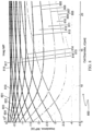
- FIGS. 7-9 show graphs of the real and imaginary parts of the impedance as a function of cell diameter of the constituent cells for a range of electromagnetic frequencies between 1 kHz and 1 MHz used during the impedance measurement.
- FIG. 7 shows a graph 700 of the real component of impedance plotted against cell diameter for a variety of electromagnetic frequencies.
- curves 701, 702, 703, 704, 705, 706, 707, 708, 709, 710, 711, 712, 713, 714, 715, 716, 717, 718, and 719 correspond to electromagnetic frequencies of 1 kHz, 2 kHz, 3 kHz, 4 kHz, 6 kHz, 9 kHz, 13 kHz, 18 kHz, 26 kHz, 38 kHz, 55 kHz, 78 kHz, 113 kHz, 162 kHz, 234 kHz, 336 kHz, 483 kHz, 695 kHz, and 1000 kHz, respectively.
- curves 801, 802, 803, 804, 805, 806, 807, 808, 809, 810, 811, 812, 813, 814, 815, 816, 817, 818, and 819 correspond to electromagnetic frequencies of 1 kHz, 2 kHz, 3 kHz, 4 kHz, 6 kHz, 9 kHz, 13 kHz, 18 kHz, 26 kHz, 38 kHz, 55 kHz, 78 kHz, 113 kHz, 162 kHz, 234 kHz, 336 kHz, 483 kHz, 695 kHz, and 1000 kHz, respectively.
- FIG. 9 shows a graph 900 of both the real and imaginary parts of the impedance plotted against frequency for different cell diameters of constituent cells.
- curves 901, 902, 903, 904, 905, 906, 907, 908, 909, 910, and 911 correspond to the real part of the impedance for cell diameters of 5 ⁇ m, 6 ⁇ m, 7 ⁇ m, 8 ⁇ m, 9 ⁇ m, 10 ⁇ m, 13 ⁇ m, 16 ⁇ m, 19 ⁇ m, 22 ⁇ m, and 25 ⁇ m, respectively.
- curves 912, 913, 914, 915, 916, 917, 918, 919, 920, 921, and 922 correspond to the imaginary part of the impedance for cell diameters of 5 ⁇ m, 6 ⁇ m, 7 ⁇ m, 8 ⁇ m, 9 ⁇ m, 10 ⁇ m, 13 ⁇ m, 16 ⁇ m, 19 ⁇ m, 22 ⁇ m, and 25 ⁇ m, respectively.
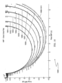
- FIG. 10 shows a graph 1000 of the real part of the impedance plotted against the imaginary part of the impedance for a variety of different cell diameters of constituent cells.
- curves 1001, 1002, 1003, 1004, 1005, 1006, 1007, 1008, 1009, 1010, and 1011 correspond to cell diameters of 5 ⁇ m, 6 ⁇ m, 7 ⁇ m, 8 ⁇ m, 9 ⁇ m, 10 ⁇ m, 13 ⁇ m, 16 ⁇ m, 19 ⁇ m, 22 ⁇ m, and 25 ⁇ m respectively.
- the curves 1001-1011 further contain information about the electromagnetic frequency applied to the constituent cells. From right to left, the frequency increases along the clockwise direction of the curve from about 100 Hz on the far right, to about 1 MHz on the far left.
- a Cole-Cole plot as shown in FIG. 10 can be constructed based on the data shown in FIGS. 7-9 .
- FIGS. 7-9 can be used to infer the cell size.
- the impedance of an array of PCIC blocks i.e. the IMP
- the impedance of an array of PCIC blocks can be easily deduced from the impedance of one PCIC block, the imp , through: IMP ⁇ D a D a 2 imp ⁇ a D imp
- D is the side length of a cube of the tissue (or tumor)
- a is the side length of the PCIC block.
- FIGS. 7-9 indicate that there are preferable frequencies that should be used in the impedance tomography. As seen, for example, in FIG. 7 up to frequencies of about 30kHz the impedance (real component) vs.
- the impedance tomography should preferably be performed at frequencies that provide unique cell sizes.
- the optimal treatment frequency can be determined on the basis of curves such as those depicted in FIG. 1 . Note that for the calculations presented in FIGS. 7-9 , the elementary cube of tissue (or tumor) is chosen to have a size of 1mm. Other parameters used in the calculations shown in FIG. 7-9 can be found in Table 1 as shown in FIG. 13 . In alternative cases, the data from FIG. 10 can be used to infer the cell size once the impedance has been determined.
- FIG. 10 shows a Cole-Cole plot that can be used to determine the size of a cell based on an impedance measurement.
- the Cole-Cole plot shows the impedance spectrum of the constituent cells as a function of the cell diameter. Note that in cases where both the tumor cell size, area of necrosis, cyst or level of vascularization change with time a potential error may be introduced by the impedance changes resulting from the changes in fluid or blood volume within the tumor. This can be corrected for along two pathways. When the fluid (blood, cyst fluid) volume is large enough, it can be detected by the CT and the impedance tomography images and thus non affected areas can be selected for the computation.
- corrections can be made on the basis of the fact that the cell membranes of the cell mass have both capacitive and resistive i.e. real and imaginary components while the fluids and blood are, to a good approximation, primarily resistive elements.
- the correction is based on the construction of a Cole - Cole plot (see the example given in FIG. 10 ) from the tumor impedance values as determined by impedance tomography. In our case, these measurements are carried out at frequencies in the range dictated by the requirements of the Cole - Cole plot for tissue rather than by the optimal frequency requirements of impedance tomography. Note that the changes in the blood content of the tumor will be reflected mainly in the resistive aspect of the Cole - Cole plot. Utilizing the ratio between the impedance of the tumor and the tissue surrounding the tumor may add to the accuracy.
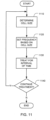
- FIG. 11 shows a method for adaptively treating a tumor with electromagnetic radiation.
- the method includes determining a cell size (step 1110).
- the cell size can be determined by first locating the tumor by a conventional imaging method, such as CT, MRI, or PET.
- the cell size can also be determined from histological sections made of samples obtained by biopsies of the tumor taken from the specific patient.
- the cell size can also be predicted based on the type of cancer involved.
- IEIT inverse electrical impedance tomography
- Standard EIT is carried out by applying an alternating electric field of selected frequencies to the body in the relevant area by appropriate electrodes while measuring the surface potential distribution by means of additional electrodes.
- FIG. 4 On the basis of this information a 3D image of the impedance of the selected area is constructed, as illustrated in FIG. 4 .
- This type of procedure is normally done in order to determine whether there is a tumor (characterized by an area with impedance that is different from the normal surroundings) in the scanned area.
- the standard alternating field/current frequency is replaced by one that is best suited for cell size determination.
- FIGS. 7-10 show exemplary frequencies suitable for carrying out IEIT.
- a frequency of 38 kHz may be preferable when determining cell size via IEIT.
- the method also includes setting a frequency based on the determined cell size (step 1120).
- the frequency can be selected on the basis of curves such as those depicted in FIG. 1 .
- the treatment frequency adjustment preferably occurs before the initialization of treatment and, according to this method, readjustment continues during the treatment, the duration of which may be months and even years.
- the method also includes treating the tumor for an interval of time (step 1130), using the new treatment frequency.
- the treatment frequency can include two or more frequencies that can be applied to the tumor either sequentially or simultaneously.
- the initial setting of the frequency is preferably selected by first determining or estimating the average size of the tumor cell and spectrum of cell sizes in step 1110.
- the initial size is preferably determined from histological sections made of samples obtained by biopsies of the tumor taken from the specific patient. But it can also be set using a prediction that is based on the type of cancer or using the impedance approach described in relation to FIGS. 7-9 . After a suitable interval of time has elapsed (e.g., a few weeks or months), a decision to continue treatment is made (step 1140). If the treatment is to be continued, processing returns to step 1110, where the next cell size determination is made. Otherwise, the treatment adjustment ends.
- a suitable interval of time e.g., a few weeks or months
- the tumor cell size is preferably evaluated periodically, e.g., every 1-3 months, preferably using one or more of the following three approaches: (1) tumor biopsies, (2) the algorithms described herein that relate the cell size to the patient's tumor impedance as determined by special procedures, or (3) a data base look-up table. If the cell size has changed, the treating field frequency is adjusted accordingly in step 1120. The new treatment frequency is then used in step 1130.
- FIG. 12 is a block diagram of a system that can apply TTFields with the different frequencies to the patient.
- the core of the system is an AC signal generator 1200 whose output is hooked up to at least one pair of electrodes E1.
- at least one additional pair of electrodes E2 is also hooked up to additional outputs of the signal generator.
- the signals are preferably applied to the different pairs of electrodes sequentially in order to switch the direction of the electric field, as described in US patent 7,805,201 .
- the AC signal generator 1200 has a control that changes the frequency of the signals that are generated. In some cases, this control can be as simple as a knob that is built in to the signal generator. But more preferably, the AC signal generator 1200 is designed to respond to a signal that arrives on a control input, and the frequency control 1202 sends a suitable signal (e.g., an analog or digital signal) to the control input of the AC signal generator 1200 to command the signal generator to generate an output at the desired frequency.
- the frequency control 1202 can send a frequency indication to the AC signal generator 1200 based on a measured or estimated cell diameter. The cell diameter can be determined by a histological measurement or by IEIT.
- an optimal treatment frequency can be determined.
- the frequency control 1202 can then send a control signal to the AC signal generator 1200 to set the frequency of the AC signal generator to the optimal treatment frequency.
- a processor can be coupled to the frequency control 1202 to automate the process of selecting an optimal treatment frequency based on a measured or estimated cell diameter.
- the processor can receive information about the measured or estimated cell size and then determine an optimal treatment frequency based on the received information. After determining an optimal treatment frequency, the processor can send a control signal to the frequency control 1202 that causes the frequency control 1202 to send a signal to the AC signal generator 1200 that causes the AC signal generator to output the optimal treatment frequency.
- IEIT could be used to measure the impedance of a group of patient cells.
- the determined impedance of the group of patient cells could then be used to adjust a parameter of the treatment.
- the treatment could be a surgery or a therapy such as chemotherapy, radiation therapy, pharmacotherapy, or nutritional therapy.
- the determined impedance of the patient cells can be used to estimate the size of cells in the group of patient cells. A parameter of the treatment could then be adjusted based on the estimated cell size.
Description
- The present invention relates, generally, to an apparatus for adaptively treating a tumor with an alternating electric field, the apparatus to be used in the long term treatment of tumors.
- Living organisms proliferate by cell division, including tissues, cell cultures, microorganisms (such as bacteria, mycoplasma, yeast, protozoa, and other single-celled organisms), fungi, algae and plant cells.
- When in the process of dividing, cells of organisms can be destroyed, or their proliferation controlled, by methods that are based on the sensitivity of the dividing cells of these organisms to certain chemical or physical agents.
- It is well known that tumors, particularly malignant or cancerous tumors, grow uncontrollably compared to normal tissue. Such expedited growth enables tumors to occupy an ever-increasing space and to damage or destroy tissues and organs adjacent thereto. Furthermore, certain cancers are characterized by an ability to spread metastases to new locations where the metastatic cancer cells grow into additional tumors.
- The rapid growth of tumors, in general, and malignant tumors in particular, as described above, is the result of relatively frequent cell division of these cells compared to normal tissue cells. The distinguishably frequent cell division of cancer cells is the basis for the effectiveness of many existing cancer treatments, e.g., irradiation therapy and the use of various chemo-therapeutic agents. Such treatments are based on the fact that cells undergoing division are more sensitive to radiation and chemo-therapeutic agents than non-dividing cells. Because tumor cells divide much more frequently than normal cells, it is possible, to a certain extent, to selectively damage or destroy tumor cells by radiation therapy and/or chemotherapy. The actual sensitivity of cells to radiation and therapeutic agents is also dependent on specific characteristics of different types of normal or malignant cells. Unfortunately, in many cases the sensitivity of tumor cells to the applied therapeutic agent is not sufficiently higher than that of many types of normal tissues, and therefore existing cancer treatments typically cause significant damage to normal tissues, thus limiting the therapeutic effectiveness of such treatments. Also, certain types of tumors are not sensitive at all to existing methods of treatment.
- Electric fields and currents have been used for medical purposes for many years. The most common use is the generation of electric currents in a human or animal body by application of an electric field by means of a pair of conductive electrodes between which a potential difference is maintained. These electric currents are used either to exert their specific effects, i.e., to stimulate excitable tissue, or to generate heat in the body.
- Examples of the first type of application include the following: cardiac defibrillators, peripheral nerve and muscle stimulators and brain stimulators.
- Currents are used for heating, for example, in devices for tumor ablation, ablation of malfunctioning cardiac or brain tissue, cauterization, relaxation of muscle rheumatic pain and other pain.
- Another use of electric fields for medical purposes involves the utilization of high frequency oscillating fields transmitted from a source that emits an electric wave, such as an RF wave or a microwave source, which is directed at the part of the body that is of interest (i.e., a target).
- Historically, electric fields used in medical applications were separated into two types, namely (1) steady fields or fields that change at relatively slow rates, and alternating fields of low frequencies that induce corresponding electric currents in the body or tissues, and (2) high frequency alternating fields (above 1 MHz) applied to the body by means of the conducting electrodes or by means of insulated electrodes.
- The first type of electric field has been used, for example, to stimulate nerves and muscles or to pace the heart.
- In fact, such fields are used in nature to propagate signals in nerve and muscle fibers, the central nervous system (CNS) and the heart. The recording of such natural fields is the basis for the ECG, EEG, EMG and ERG. The field strength in a medium having uniform electric properties is simply the voltage applied to the stimulating/recording electrodes divided by the distance between them. The currents thus generated can be calculated by Ohm's law. Those currents, however, can have dangerous stimulatory effects on the heart and CNS and can result in potentially harmful ion concentration changes. Also, if the currents are strong enough, they can cause excessive heating in the tissues. This heating can be calculated by the power dissipated in the tissue (the product of the voltage and the current).
- When such electric fields and currents are alternating, their stimulatory power (e.g., on nerve and muscle) decreases with the frequency. At frequencies above 10 kHz, the stimulation power of the field approaches zero. This limitation is due to the fact that excitation induced by electric stimulation is normally mediated by membrane potential changes, the rate of which is limited by the resistive and capacitive properties (with time constants on the order of 1 ms) of the membrane.
- Regardless of the frequency, when such current inducing fields are applied, they are often associated with harmful side effects caused by currents. For example, one negative effect is the change in ionic concentration in the various compartments within the system, and the harmful products of the electrolysis.
- Historically, alternating fields of medium frequencies (about 50 kHz - 1 MHz) were thought not to have any biological effect except due to heating. But more recently, the usefulness of such fields has been recognized, particularly when the fields are applied to a conductive medium, such as a human body, via insulated electrodes. Under such conditions the electrodes induce capacitive currents in the body. In
US patents 7,016,725 ,7,089,054 ,7,333,852 ,7,805,201 , and8,244,345 by Palti and in a publication by Kirson (see Eilon D. Kirson, et al., Disruption of Cancer Cell Replication by Alternating Electric Fields, Cancer Res. 2004 64:3288-3295), such fields have been shown to have the capability to specifically affect cancer cells and serve, among other uses, for treating cancer. These fields are referred to herein as TTFields. - The above listed references demonstrate that the efficacy of alternating fields in specifically damaging cancer cells is frequency dependent, and also demonstrate that the optimal frequency is different for different cell types. Thus for example the optimal frequency for malignant melanoma tumor cells is 100kHz, while that for glioblastoma multiforme is 200kHz. It was further demonstrated that these differences result from the differences in cell size as shown in another publication by Kirson (see Kirson ED, Dbaly V, Tovarys F, et al. Alternating electric fields arrest cell proliferation in animal tumor models and human brain tumors. Proc Natl Acad Sci U.S.A. 2007; 104:10152-10157). Thus for each type of cancer, treatment is preferably given at a particular optimal frequency.
- The frequency used for the treatment is based on the inverse relationship between the cell size and the optimal treatment frequency as calculated by Kirson (see Kirson ED, Dbaly V, Tovarys F, et al. Alternating electric fields arrest cell proliferation in animal tumor models and human brain tumors. Proc Natl Acad Sci USA. 2007;104:10152-10157) on the basis of the maximal electric force exerted on the polar particles in the dividing tumor cell (during cytokinesis) is depicted in
FIG. 1 . Note that the experimentally determined optimal treatment frequency and histological measurements of cell size in melanoma and glioma fall reasonably well on the calculated curve. - One shortcoming of previous approaches as described above, is the use of a single fixed frequency throughout the treatment of a tumor. While the frequency may be optimal at the start of the treatment, previous approaches did not take into account the possibility that the cells in the tumor may change size as the treatment progresses. Thus, previous approaches failed to optimize the frequency of radiation directed at the tumor throughout the treatment process.
- The apparatus described herein provide a second-order improvement to the Palti and Kirson advances, based on the inventor's recognition that during the course of treatment for a particular type of cancer, the average cell size may not remain constant. As a result, the efficacy of the treatment may be improved by optimizing the frequency over time during the treatment to match expected changes in the cell size that occur over time.
- An apparatus for optimizing cancer treatment with TTFields is provided. Optimization is achieved by adjusting the frequency of the alternating electric field to the value that is clinically optimal for the specific tumor in the individual patient at different times during the course of treatment. The basis of the corresponding method is the fact that the maximal exerted force on cell components by electric field forces including dielectrophoresis forces is both cell size and frequency dependent. As a result there is an optimal treatment frequency that is dependent on the specific tumor cell size at any given moment in time. Moreover, since the cell size changes over time, the frequency should be changed to compensate for the changes in the cell size to maintain the most effective treatment.
- In one aspect, a method is described for adaptively treating a tumor with an alternating electric field. The method involves applying an alternating electric field having a first frequency to the tumor. The method further involves determining an impedance of the tumor based on a measured current while the alternating electric field is applied at the first frequency.
- Additionally, the method involves estimating a size of cells in the tumor based on the determined impedance. The method also involves selecting a second frequency based on the estimated size of cells. Moreover, the method involves applying an alternating electric field to the tumor at the second frequency to treat the tumor.
- In some cases, the method involves waiting for a period of time. The method further involves applying an alternating electric field having a third frequency to the tumor. The method further involves determining a second impedance of the tumor based on a measured current while the alternating electric field having the third frequency is applied. The method further involves estimating a second size of cells in the tumor based on the determined second impedance. The method further involves selecting a fourth frequency based on the estimated second size of cells. The method further involves applying an alternating electric field to the tumor at the fourth frequency to treat the tumor.
- In some cases, the method further involves waiting for a period of at least one week. In some cases, the method further involves determining a size, shape, type, or location of the tumor. In some cases, the method further involves estimation of the size of cells based on a Cole-Cole plot. In some cases, the method further involves imaging the tumor with CT, MRI, or PET to locate portions of the tumor not having excess blood or cyst fluid and estimating the size of cells based on a measured impedance of the located portions.
- The invention relates to an apparatus for adaptively treating a tumor with electromagnetic radiation. The apparatus includes an electrical impedance tomography device for measuring the impedance of the tumor, the electrical impedance tomography device using a frequency such that a size of cells in the tumor can be determined from the measured impedance of the tumor. The apparatus also includes an AC signal generator having a controllable output frequency. The apparatus also includes a processor for estimating the size of cells in the tumor based on the measured impedance of the tumor and setting the frequency of the AC signal generator based on the estimated size of cells in the tumor. The apparatus also includes at least one pair of electrodes operatively connected to the AC signal generator such that an alternating electric field is applied to the tumor to selectively destroy cells in the tumor.
- In some embodiments, the size of cells in the tumor is determined based on a Cole-Cole plot. In some embodiments, the apparatus further includes a CT, MRI, or PET imaging device configured to locate portions of the tumor not having excess blood or cyst fluid; and wherein the electrical impedance tomography device only measures the impedance of the located portions. In some embodiments, the electrical impedance tomography device is configured to make periodic impedance measurements. In some embodiments, the periodicity of the impedance measurements is at least one week. In some embodiments, the periodicity of the impedance measurements is at least one month. In some embodiments, the periodicity of the impedance measurements is based on a history of the tumor. In some embodiments, the periodicity of the impedance measurements is based on the type of tumor. In some embodiments, the frequency of the AC signal generator is set based on a spectrum of cell sizes. In some embodiments, the frequency of the AC signal generator is set based on an average cell size. In some embodiments, the processor computes a size of cells in the tumor based on a database look-up table.
- A method is described for adaptively treating a tumor with an alternating electric field. The method involves determining a first size of cells in the tumor. The method also involves selecting a first frequency based on the determined first size. The method also involves applying an alternating electric field to the tumor at the first frequency to treat the tumor. The method also involves waiting a period of time and subsequently determining a second size of cells in the tumor. The method also involves selecting a second frequency based on the determined second size. The method also involves applying an alternating electric field to the tumor at the second frequency to treat the tumor.
- In some cases, the method further involves the first size and the second size being determined based on a tumor biopsy. In some cases, the method further involves selecting a second treatment parameter based on the determined second impedance. The method further involves applying a treatment to the patient in accordance with the selected second treatment parameter.
- In some cases, the method further involves estimating a size of cells in the group of patient cells based on the determined impedance or the determined second impedance. The method further involves selecting a treatment parameter based on the estimated size of cells. In some cases, the medical treatment is chemotherapy. In some cases, the medical treatment is a surgery or therapy. In some cases, the therapy is acoustic therapy, pharmacotherapy, radiation therapy, or nutritional therapy.
- The advantages described above, together with further advantages, may be better understood by referring to the following description taken in conjunction with the accompanying drawings. The drawings are not necessarily to scale, emphasis instead generally being placed upon illustrating the principles of the invention.
-
FIG. 1 is a graph of a calculated relationship between the cell radius and the optimal treatment frequency. -
FIG. 2 is a graph showing cell volume in picoliters (pL) plotted against time in hours (h). -
FIG. 3 is an image showing a normal breast and a breast with a tumor. -
FIG. 4 is an image of a tumor and surrounding tissue. -
FIG. 5 is an image showing a geometrical model representation for cells in a tissue. -
FIG. 6 is a diagram showing an RC circuit equivalent of a PCIC model. -
FIG. 7 is a graph showing the real part of the impedance plotted against cell diameter for a variety of different frequencies. -
FIG. 8 is a graph showing the imaginary part of the impedance plotted against cell diameter for a variety of different frequencies. -
FIG. 9 is a graph showing the real and imaginary parts of the impedance plotted against frequency for a variety of different cell diameters. -
FIG. 10 is a graph showing a Cole-Cole plot. -
FIG. 11 is a flow chart illustrating a method for adjustment of the treatment frequency during the course of tumor treatment. -
FIG. 12 is a diagram of an apparatus for adjusting the treatment frequency of a tumor during the course of treatment. - The size of cells in a tumor can be determined throughout a treatment process utilizing TTFields. The frequency of the TTFields is then optimized based on the determined cell size. One way to determine the cell size (
step 1120 inFIG. 11 ) is to first take impedance measurements, and then use those impedance measurements to compute the cell size. The tumor impedance can be determined, for example, by in-vivo MRI electrical impedance tomography (MREIT), or by following a tumor impedance estimation method which may be termed "Inverse Electric Impedance Tomography" that is carried out as follows:
At the initial stage of the impedance estimation a CT, MRI, PET, or equivalent body/tissue imaging is made of the patient's tumor within its natural surrounding area. This image serves to determine the tumor location, size and shape of the tumor relative to specific body markers. - Next, electrical impedance tomography (EIT) of the tumor together with the surrounding area is carried out by conventional means. As is well known, Standard EIT is carried out by applying an alternating electric field of selected frequencies to the body in the relevant area by appropriate electrodes while measuring the surface potential distribution by means of additional electrodes. On the basis of this information a 3D image of the impedance of the selected area is constructed, as illustrated in
Figure 3 . This type of procedure is normally done in order to determine whether there is a tumor (characterized by an area with impedance that is different from the normal surroundings) in the scanned area. When this measurement is carried out within the framework of the Inverse Electric Impedance Tomography, the standard alternating field/current frequency is replaced by one that is best suited for cell size determination. - It is important to note that EIS/EIT produces an impedance map of an object based upon the spatial electrical characteristics throughout the volume of the object. When a current is injected into an object, by Ohm's law the voltage drop will be proportional to the impedance of the object as long as the object has passive electrical characteristics. In EIS, a known current is injected into the surface and the voltage is measured at a number of points (electrodes) on the surface of the object. The resolution of the resultant image is dependent on the number of electrodes. Areas of low impedance typically appear on an EIS map as areas that have greater intensity (whiter). A measure of the electrical properties of the volume within the surface is obtained from these maps. An example of a device designed to detect tumors by EIT is the Siemens TS2000.
- In this case, an inverse process is being carried out as follows: In stage one above the existence and location of the tumor have been established using CT, MRI or PET. The tumor coordinates thus obtained are provided to the processor that constructs the EIT image so that it will provide the calculated average impedance values at the selected tumor area as depicted in
FIG. 4 . - The impedance values of the specific tumor areas are registered for comparison with subsequent values obtained at later times. Note that the impedance is a function of the alternating field frequency used in the EIT. The impedance of the selected tumor area is now converted to average cell size or a spectrum of cell sizes on the basis of the electric impedance vs. cell size curves or tables of the relevant tumor, if available, or otherwise, on the calculations based on a geometric or prismatic cell in a cube (PCIC) model.
-
FIG. 1 shows agraph 100 that includes acalculated relationship 104 between the cell radius (µm) and the optimal treatment frequency (kHz) as calculated on the basis of the maximal electric force exerted on the polar particles in the dividing tumor cell (during cytokinesis).FIG. 1 also shows experimentally determined treatment frequencies forglioma 108 andmelanoma 112. Note that the experimentally determined optimal treatment frequencies and histological measurements of cell size in melanoma and glioma fall reasonably well on the calculated curve. -
FIG. 2 shows agraph 200 of cell volume in picoliters (pL) plotted against time in hours (h).FIG. 2 illustrates how the cell size can change over time in a cell culture of A2780 human ovarian cancer cell line exposed to TTFields. It can be seen that in this case during the first 72 hours of treatment the cell volume increases. For example,FIG. 2 shows that for cells not exposed to TTFields (curve 204), the cell volume remains approximately constant, having a value of about 2 pL. Additionally,FIG. 2 shows that for cells exposed to TTFields (curves 201-203), the cell volume increase from a value of about 2 pL to a value of about 3pL over the course of about 72 hours. Similarly, during long duration treatment in vivo, the cell volume changes may also differ. For example, in one patient who had three GBM biopsies over a period of two years of treatment with TTFields, histological sections indicated a 30% decrease in cell volume. In view of these volume changes with time, a frequency adjustment procedure is preferably repeated during the course of treatment (e.g., every few weeks or months), preferably depending on the type of tumor and the history of the tumor in the specific patient. -
FIG. 3 shows animage 300 comprising an image of anormal breast 304 and an image of a breast with atumor 308. Theimages breast tumor 312 appears as a white patch withinimage 308. Theimage 308 shows the shape, size, type, and location of thetumor 312. -
FIG. 4 is agraph 400 of an electric impedance tomography (EIT) image of a tumor together with the surrounding areas, showing the electrical conductivity (S/m) of the imaged region plotted against position (m). The tumor is located in the rectangular region 404 of the graph. -
FIG. 5 shows ageometrical model representation 500 for cells in a tissue. Following Gimsa (A unified resistor-capacitor model for impedance, dielectrophoresis, electrorotation, and induced transmembrane potential. Gimsa J, Wachner D. Biophys J. 1998 Aug; 75(2): 1107-16.), the tissue can be modeled as elementary cubes 504, in which each elementary cube 504 is embedded with an elementary cell of prismatic geometry 508. Themodel representation 500 can be referred to as a prismatic cell in a cube model (PCIC). Thegeometrical model 500 can be mirror symmetric on the mid-plane of the cube. -
FIG. 6 shows an RC circuit 600 (i.e. a circuit containing resistors and capacitors) equivalent of a PCIC model, corresponding to one half of the prismatic cell in a cube. For a homogeneous medium, i, which contains the following tissue/cell elements: intracellular medium, extracellular medium and outer cell membrane, the impedance is modeled as a parallel RC circuit with a corresponding impedance (FIG. 6 ):
- The complex conductivity can be modeled as:

- The equivalent RC circuit can be used to model a homogeneous medium that contains an
intracellular medium 603,extracellular medium 601, andouter cell membrane 602. In cases where the geometrical model is mirror symmetric on the mid-plane of the cube, such as is shown inFIG. 5 , the impedance of only one half of the equivalent circuit needs to be solved and the total impedance is just twice the calculated one. -
FIGS. 7-9 show graphs of the real and imaginary parts of the impedance as a function of cell diameter of the constituent cells for a range of electromagnetic frequencies between 1 kHz and 1 MHz used during the impedance measurement.FIG. 7 shows a graph 700 of the real component of impedance plotted against cell diameter for a variety of electromagnetic frequencies. For example, curves 701, 702, 703, 704, 705, 706, 707, 708, 709, 710, 711, 712, 713, 714, 715, 716, 717, 718, and 719 correspond to electromagnetic frequencies of 1 kHz, 2 kHz, 3 kHz, 4 kHz, 6 kHz, 9 kHz, 13 kHz, 18 kHz, 26 kHz, 38 kHz, 55 kHz, 78 kHz, 113 kHz, 162 kHz, 234 kHz, 336 kHz, 483 kHz, 695 kHz, and 1000 kHz, respectively.FIG. 8 shows agraph 800 of the imaginary component of impedance plotted against cell diameter for a variety of electromagnetic frequencies. For example, curves 801, 802, 803, 804, 805, 806, 807, 808, 809, 810, 811, 812, 813, 814, 815, 816, 817, 818, and 819 correspond to electromagnetic frequencies of 1 kHz, 2 kHz, 3 kHz, 4 kHz, 6 kHz, 9 kHz, 13 kHz, 18 kHz, 26 kHz, 38 kHz, 55 kHz, 78 kHz, 113 kHz, 162 kHz, 234 kHz, 336 kHz, 483 kHz, 695 kHz, and 1000 kHz, respectively.FIG. 9 shows agraph 900 of both the real and imaginary parts of the impedance plotted against frequency for different cell diameters of constituent cells. For example, curves 901, 902, 903, 904, 905, 906, 907, 908, 909, 910, and 911 correspond to the real part of the impedance for cell diameters of 5 µm, 6 µm, 7 µm, 8 µm, 9 µm, 10 µm, 13 µm, 16 µm, 19 µm, 22 µm, and 25 µm, respectively. Additionally, curves 912, 913, 914, 915, 916, 917, 918, 919, 920, 921, and 922 correspond to the imaginary part of the impedance for cell diameters of 5 µm, 6 µm, 7 µm, 8 µm, 9 µm, 10 µm, 13 µm, 16 µm, 19 µm, 22 µm, and 25 µm, respectively.FIG. 10 shows agraph 1000 of the real part of the impedance plotted against the imaginary part of the impedance for a variety of different cell diameters of constituent cells. For example, curves 1001, 1002, 1003, 1004, 1005, 1006, 1007, 1008, 1009, 1010, and 1011 correspond to cell diameters of 5 µm, 6 µm, 7 µm, 8 µm, 9 µm, 10 µm, 13 µm, 16 µm, 19 µm, 22 µm, and 25 µm respectively. The curves 1001-1011 further contain information about the electromagnetic frequency applied to the constituent cells. From right to left, the frequency increases along the clockwise direction of the curve from about 100 Hz on the far right, to about 1 MHz on the far left. A Cole-Cole plot as shown inFIG. 10 can be constructed based on the data shown inFIGS. 7-9 . - Once the impedance of the tumor is known,
FIGS. 7-9 can be used to infer the cell size. The impedance of an array of PCIC blocks, i.e. the IMP, can be easily deduced from the impedance of one PCIC block, the imp, through:
FIGS. 7-9 indicate that there are preferable frequencies that should be used in the impedance tomography. As seen, for example, inFIG. 7 up to frequencies of about 30kHz the impedance (real component) vs. cell size curves have a peak, i.e. there are cell sizes with the same impedance (two relevant solutions to the equations) leaving an ambiguity as to the actual size. However, for higher frequencies the curves are monotonous and there is a unique solution/size corresponding to each impedance value. Thus the impedance tomography should preferably be performed at frequencies that provide unique cell sizes. Once the cell size is determined, the optimal treatment frequency can be determined on the basis of curves such as those depicted inFIG. 1 . Note that for the calculations presented inFIGS. 7-9 , the elementary cube of tissue (or tumor) is chosen to have a size of 1mm. Other parameters used in the calculations shown inFIG. 7-9 can be found in Table 1 as shown inFIG. 13 . In alternative cases, the data fromFIG. 10 can be used to infer the cell size once the impedance has been determined. -
FIG. 10 shows a Cole-Cole plot that can be used to determine the size of a cell based on an impedance measurement. The Cole-Cole plot shows the impedance spectrum of the constituent cells as a function of the cell diameter. Note that in cases where both the tumor cell size, area of necrosis, cyst or level of vascularization change with time a potential error may be introduced by the impedance changes resulting from the changes in fluid or blood volume within the tumor. This can be corrected for along two pathways. When the fluid (blood, cyst fluid) volume is large enough, it can be detected by the CT and the impedance tomography images and thus non affected areas can be selected for the computation. Alternatively corrections can be made on the basis of the fact that the cell membranes of the cell mass have both capacitive and resistive i.e. real and imaginary components while the fluids and blood are, to a good approximation, primarily resistive elements. Here the correction is based on the construction of a Cole - Cole plot (see the example given inFIG. 10 ) from the tumor impedance values as determined by impedance tomography. In our case, these measurements are carried out at frequencies in the range dictated by the requirements of the Cole - Cole plot for tissue rather than by the optimal frequency requirements of impedance tomography. Note that the changes in the blood content of the tumor will be reflected mainly in the resistive aspect of the Cole - Cole plot. Utilizing the ratio between the impedance of the tumor and the tissue surrounding the tumor may add to the accuracy. -
FIG. 11 shows a method for adaptively treating a tumor with electromagnetic radiation. The method includes determining a cell size (step 1110). The cell size can be determined by first locating the tumor by a conventional imaging method, such as CT, MRI, or PET. The cell size can also be determined from histological sections made of samples obtained by biopsies of the tumor taken from the specific patient. The cell size can also be predicted based on the type of cancer involved. After locating the tumor, inverse electrical impedance tomography (IEIT) of the tumor together with the surrounding area can be performed. As is well known, Standard EIT is carried out by applying an alternating electric field of selected frequencies to the body in the relevant area by appropriate electrodes while measuring the surface potential distribution by means of additional electrodes. - On the basis of this information a 3D image of the impedance of the selected area is constructed, as illustrated in
FIG. 4 . This type of procedure is normally done in order to determine whether there is a tumor (characterized by an area with impedance that is different from the normal surroundings) in the scanned area. When this measurement is carried out within the framework of the IEIT, the standard alternating field/current frequency is replaced by one that is best suited for cell size determination.FIGS. 7-10 show exemplary frequencies suitable for carrying out IEIT. - For example, referring to
FIG. 7 , a frequency of 38 kHz (corresponding to curve 711) may be preferable when determining cell size via IEIT. The method also includes setting a frequency based on the determined cell size (step 1120). The frequency can be selected on the basis of curves such as those depicted inFIG. 1 . The treatment frequency adjustment preferably occurs before the initialization of treatment and, according to this method, readjustment continues during the treatment, the duration of which may be months and even years. The method also includes treating the tumor for an interval of time (step 1130), using the new treatment frequency. In some cases, the treatment frequency can include two or more frequencies that can be applied to the tumor either sequentially or simultaneously. The initial setting of the frequency is preferably selected by first determining or estimating the average size of the tumor cell and spectrum of cell sizes instep 1110. - The initial size is preferably determined from histological sections made of samples obtained by biopsies of the tumor taken from the specific patient. But it can also be set using a prediction that is based on the type of cancer or using the impedance approach described in relation to
FIGS. 7-9 . After a suitable interval of time has elapsed (e.g., a few weeks or months), a decision to continue treatment is made (step 1140). If the treatment is to be continued, processing returns to step 1110, where the next cell size determination is made. Otherwise, the treatment adjustment ends. The tumor cell size is preferably evaluated periodically, e.g., every 1-3 months, preferably using one or more of the following three approaches: (1) tumor biopsies, (2) the algorithms described herein that relate the cell size to the patient's tumor impedance as determined by special procedures, or (3) a data base look-up table. If the cell size has changed, the treating field frequency is adjusted accordingly instep 1120. The new treatment frequency is then used instep 1130. -
FIG. 12 is a block diagram of a system that can apply TTFields with the different frequencies to the patient. The core of the system is anAC signal generator 1200 whose output is hooked up to at least one pair of electrodes E1. Preferably, at least one additional pair of electrodes E2 is also hooked up to additional outputs of the signal generator. The signals are preferably applied to the different pairs of electrodes sequentially in order to switch the direction of the electric field, as described inUS patent 7,805,201 . - The
AC signal generator 1200 has a control that changes the frequency of the signals that are generated. In some cases, this control can be as simple as a knob that is built in to the signal generator. But more preferably, theAC signal generator 1200 is designed to respond to a signal that arrives on a control input, and thefrequency control 1202 sends a suitable signal (e.g., an analog or digital signal) to the control input of theAC signal generator 1200 to command the signal generator to generate an output at the desired frequency. Thefrequency control 1202 can send a frequency indication to theAC signal generator 1200 based on a measured or estimated cell diameter. The cell diameter can be determined by a histological measurement or by IEIT. - Once the cell diameter is determined, an optimal treatment frequency can be determined. The
frequency control 1202 can then send a control signal to theAC signal generator 1200 to set the frequency of the AC signal generator to the optimal treatment frequency. A processor can be coupled to thefrequency control 1202 to automate the process of selecting an optimal treatment frequency based on a measured or estimated cell diameter. The processor can receive information about the measured or estimated cell size and then determine an optimal treatment frequency based on the received information. After determining an optimal treatment frequency, the processor can send a control signal to thefrequency control 1202 that causes thefrequency control 1202 to send a signal to theAC signal generator 1200 that causes the AC signal generator to output the optimal treatment frequency. - While the methods described thus far have been focused on adaptively treating a tumor with TTFields, the methods have broader implications. In various cases, IEIT could be used to measure the impedance of a group of patient cells. The determined impedance of the group of patient cells could then be used to adjust a parameter of the treatment. The treatment could be a surgery or a therapy such as chemotherapy, radiation therapy, pharmacotherapy, or nutritional therapy. In some cases, the determined impedance of the patient cells can be used to estimate the size of cells in the group of patient cells. A parameter of the treatment could then be adjusted based on the estimated cell size.
- The terminology used herein is for the purpose of describing particular apparatus and is not intended to be limiting of the inventive concepts. It will be understood that, although the terms first, second and third are used herein to describe various elements, components, regions, layers and/or sections, these elements, components, regions, layers and/or sections should not be limited by these terms. These terms are only used to distinguish one element, component, region, layer or section from another element, component, region, layer or section.
- The invention is defined by the following claims.
Claims (11)
- An apparatus for adaptively treating a tumor with an alternating electric field, the apparatus comprising:an AC signal generator (1200) having a controllable output frequency; andat least one pair of electrodes (E1, E2) operatively connected to the AC signal generator (1200) for applying an alternating electric field at the output frequency to the tumor selectively to destroy cells in the tumor;characterized by:
a processor configured, during use of the apparatus in treating the tumor, to estimate a size of cells in the tumor and adjust the output frequency of the AC signal generator (1200) based on the estimated size of cells in the tumor. - The apparatus of claim 1, wherein the processor is configured, at a first time, to estimate a first size of the cells in the tumor and set the output frequency of the AC signal generator (1200) to a first frequency based on the estimated first size of the cells in the tumor, and, at a second time, to estimate a second size of the cells in the tumor and set the output frequency of the AC signal generator (1200) to a second frequency based on the estimated second size of the cells in the tumor.
- The apparatus of claim 1, wherein the processor is configured to estimate the size of the cells in the tumor using a database look-up table.
- The apparatus of claim 1, wherein the processor is configured to estimate the size of the cells in the tumor based on the type of cancer.
- The apparatus of claim 1, wherein the processor is configured to estimate the size of the cells in the tumor based on electrical impedance tomography of the cells in the tumor.
- The apparatus of claim 1, wherein the processor is configured to estimate the size of the cells in the tumor based on imaging of the cells in the tumor, optionally the imaging is selected from computed tomography (CT), magnetic resonance imaging (MRI) and positron emission tomography (PET).
- The apparatus of claim 1, wherein the processor is configured to estimate the size of the cells in the tumor based on histological sections of the cells in the tumor.
- The apparatus of claim 1, wherein the processor is configured periodically to estimate the size of the cells in the tumor.
- The apparatus of claim 8, wherein the periodicity of the estimation of the size of the cells in the tumor is based on a history of the tumor.
- The apparatus of claim 8, wherein the periodicity of the estimation of the size of the cells in the tumor is based on the type of the tumor.
- The apparatus of claim 1, wherein the estimated size of the cells in the tumor is an average cell size.
Applications Claiming Priority (4)
| Application Number | Priority Date | Filing Date | Title |
|---|---|---|---|
| US201361819717P | 2013-05-06 | 2013-05-06 | |
| EP14752362.5A EP2994045B1 (en) | 2013-05-06 | 2014-05-06 | Apparatus for treating a tumor with an alternating electric field and for selecting a treatment frequency based on estimated cell size |
| PCT/IB2014/000688 WO2014181167A1 (en) | 2013-05-06 | 2014-05-06 | Apparatus and methods for treating a tumor with an alternating electric field and for selecting a treatment frequency based on estimated cell size |
| EP19174518.1A EP3569144B1 (en) | 2013-05-06 | 2014-05-06 | Apparatus for treating a tumor with an alternating electric field and for selecting a treatment frequency based on estimated cell size |
Related Parent Applications (3)
| Application Number | Title | Priority Date | Filing Date |
|---|---|---|---|
| EP14752362.5A Division EP2994045B1 (en) | 2013-05-06 | 2014-05-06 | Apparatus for treating a tumor with an alternating electric field and for selecting a treatment frequency based on estimated cell size |
| EP19174518.1A Division EP3569144B1 (en) | 2013-05-06 | 2014-05-06 | Apparatus for treating a tumor with an alternating electric field and for selecting a treatment frequency based on estimated cell size |
| EP19174518.1A Division-Into EP3569144B1 (en) | 2013-05-06 | 2014-05-06 | Apparatus for treating a tumor with an alternating electric field and for selecting a treatment frequency based on estimated cell size |
Publications (2)
| Publication Number | Publication Date |
|---|---|
| EP3824805A1 EP3824805A1 (en) | 2021-05-26 |
| EP3824805B1 true EP3824805B1 (en) | 2023-04-26 |
Family
ID=51355556
Family Applications (3)
| Application Number | Title | Priority Date | Filing Date |
|---|---|---|---|
| EP20217359.7A Active EP3824805B1 (en) | 2013-05-06 | 2014-05-06 | Apparatus for treating a tumor with an alternating electric field and for selecting a treatment frequency based on estimated cell size |
| EP14752362.5A Active EP2994045B1 (en) | 2013-05-06 | 2014-05-06 | Apparatus for treating a tumor with an alternating electric field and for selecting a treatment frequency based on estimated cell size |
| EP19174518.1A Active EP3569144B1 (en) | 2013-05-06 | 2014-05-06 | Apparatus for treating a tumor with an alternating electric field and for selecting a treatment frequency based on estimated cell size |
Family Applications After (2)
| Application Number | Title | Priority Date | Filing Date |
|---|---|---|---|
| EP14752362.5A Active EP2994045B1 (en) | 2013-05-06 | 2014-05-06 | Apparatus for treating a tumor with an alternating electric field and for selecting a treatment frequency based on estimated cell size |
| EP19174518.1A Active EP3569144B1 (en) | 2013-05-06 | 2014-05-06 | Apparatus for treating a tumor with an alternating electric field and for selecting a treatment frequency based on estimated cell size |
Country Status (12)
| Country | Link |
|---|---|
| US (1) | US9655669B2 (en) |
| EP (3) | EP3824805B1 (en) |
| JP (1) | JP6453853B2 (en) |
| CN (2) | CN105530862B (en) |
| CA (1) | CA2911491C (en) |
| DK (2) | DK2994045T3 (en) |
| ES (2) | ES2741004T3 (en) |
| HK (1) | HK1216596A1 (en) |
| HU (1) | HUE062103T2 (en) |
| PL (2) | PL3824805T3 (en) |
| PT (1) | PT2994045T (en) |
| WO (1) | WO2014181167A1 (en) |
Families Citing this family (70)
| Publication number | Priority date | Publication date | Assignee | Title |
|---|---|---|---|---|
| US10779875B2 (en) | 2013-05-06 | 2020-09-22 | Novocure Gmbh | Optimizing treatment using TTfields by changing the frequency during the course of long term tumor treatment |
| US10188851B2 (en) | 2015-10-28 | 2019-01-29 | Novocure Limited | TTField treatment with optimization of electrode positions on the head based on MRI-based conductivity measurements |
| US10821283B2 (en) * | 2016-04-04 | 2020-11-03 | Novocure Gmbh | Reducing motility of cancer cells using tumor treating fields (TTFields) |
| US9610458B1 (en) | 2016-07-01 | 2017-04-04 | Anapole Technologies, Inc. | Treating disease with resonance generating electromagnetic fields |
| US10279190B2 (en) * | 2016-07-01 | 2019-05-07 | Anapole Technologies Inc. | Treating disease with resonance generating electromagnetic fields |
| CN116747438A (en) | 2016-08-18 | 2023-09-15 | 诺沃库勒有限责任公司 | Temperature measurement in an array for delivering tumor treatment electric fields |
| EP3571503A1 (en) | 2017-01-19 | 2019-11-27 | Moshe Giladi | System for viewing cell cultures under a microscope whilst applying ttfields |
| CN107224668A (en) * | 2017-07-19 | 2017-10-03 | 重庆半岛医疗科技有限公司 | A kind of RF therapy device of frequency conversion |
| WO2019060298A1 (en) | 2017-09-19 | 2019-03-28 | Neuroenhancement Lab, LLC | Method and apparatus for neuroenhancement |
| US20190117969A1 (en) * | 2017-10-23 | 2019-04-25 | Cardiac Pacemakers, Inc. | Medical devices for treatment of cancer with electric fields |
| US20190117973A1 (en) * | 2017-10-23 | 2019-04-25 | Cardiac Pacemakers, Inc. | Electric field cancer therapy devices with feedback mechanisms and diagnostics |
| US11338135B2 (en) | 2017-10-23 | 2022-05-24 | Cardiac Pacemakers, Inc. | Medical devices for cancer therapy with electric field shaping elements |
| EP3710102A4 (en) * | 2017-11-17 | 2021-08-04 | AbbVie Inc. | Methods of treating glioblastoma |
| US11717686B2 (en) | 2017-12-04 | 2023-08-08 | Neuroenhancement Lab, LLC | Method and apparatus for neuroenhancement to facilitate learning and performance |
| EP4218641A1 (en) | 2017-12-26 | 2023-08-02 | Galvanize Therapeutics, Inc. | Optimization of energy delivery for various applications |
| EP3731749A4 (en) | 2017-12-31 | 2022-07-27 | Neuroenhancement Lab, LLC | System and method for neuroenhancement to enhance emotional response |
| KR102118639B1 (en) * | 2018-02-26 | 2020-06-05 | 주식회사 루트로닉 | A rf treatment apparatus and a method for controlling that |
| KR102038007B1 (en) * | 2018-02-26 | 2019-10-29 | 주식회사 루트로닉 | A medical rf apparatus and a method for controlling it |
| US10953209B2 (en) | 2018-03-28 | 2021-03-23 | Board Of Regents Of The University Of Texas System | Treating tumors using TTFields combined with a PARP inhibitor |
| WO2019197973A1 (en) | 2018-04-09 | 2019-10-17 | Moshe Giladi | Treating tumors with ttfields and an aurora kinase inhibitor |
| WO2019197999A1 (en) | 2018-04-10 | 2019-10-17 | Zeev Bomzon | Low frequency (<1 mhz) ac conductivity estimates derived from two mri images having different repetition times |
| US11364361B2 (en) | 2018-04-20 | 2022-06-21 | Neuroenhancement Lab, LLC | System and method for inducing sleep by transplanting mental states |
| CN116159242A (en) | 2018-07-03 | 2023-05-26 | 埃德温·阊 | Enhancement of cell membrane permeability using alternating electric fields |
| AU2019301956B2 (en) | 2018-07-10 | 2023-04-13 | Novocure Gmbh | Inhibiting viral infection using alternating electric fields |
| US11179322B2 (en) | 2018-07-10 | 2021-11-23 | Novocure Gmbh | Methods and compositions for treating tumors with TTFields and sorafenib |
| SG11202012567PA (en) | 2018-07-18 | 2021-01-28 | Novocure Gmbh | Using power loss density and related measures to quantify the dose of tumor treating fields (ttfields) |
| SG11202012592WA (en) | 2018-08-23 | 2021-01-28 | Carsten Hagemann | Using alternating electric fields to increase permeability of the blood brain barrier |
| US11623085B2 (en) | 2018-08-29 | 2023-04-11 | Regents Of The University Of Minnesota | Devices and methods for treatment of tumors using electromagnetic signal |
| US11160977B2 (en) | 2018-09-04 | 2021-11-02 | Novocure Gmbh | Delivering tumor treating fields (TTFields) to the infratentorial brain |
| US11020585B2 (en) | 2018-09-07 | 2021-06-01 | Novocure Gmbh | Treating autoimmune diseases using an alternating electric field to reduce the proliferation of t-cells |
| CA3112564A1 (en) | 2018-09-14 | 2020-03-19 | Neuroenhancement Lab, LLC | System and method of improving sleep |
| US11241577B2 (en) | 2018-10-15 | 2022-02-08 | Novocure Gmbh | Generating tumor treating fields (TTFields) with high uniformity throughout the brain |
| WO2020084596A1 (en) | 2018-10-25 | 2020-04-30 | Zeev Bomzon | Delivering alternating electric fields (e.g., ttfields) to a subject's spinal anatomy |
| CA3110448C (en) | 2018-11-19 | 2023-12-19 | Novocure Gmbh | Arrays for delivering tumor treating fields (ttfields) with selectively addressable sub-elements |
| KR20230164208A (en) | 2018-11-29 | 2023-12-01 | 노보큐어 게엠베하 | Enhanced-flexibility transducer arrays for delivering ttfields (tumor treating fields) |
| EP3961565A1 (en) | 2019-01-08 | 2022-03-02 | Novocure GmbH | Evaluating quality of segmentation of an image into different types of tissue for planning treatment using tumor treating fields (ttfields) |
| US11027143B2 (en) | 2020-02-06 | 2021-06-08 | Vivek K. Sharma | System and methods for treating cancer cells with alternating polarity magnetic fields |
| CN113692302A (en) | 2019-02-07 | 2021-11-23 | V·K·沙玛 | System and method for treating cancer cells with alternating polarity magnetic fields |
| US11344740B2 (en) | 2019-02-07 | 2022-05-31 | Asha Medical, Inc. | System and methods for treating cancer cells with alternating polarity magnetic fields |
| WO2020170164A1 (en) * | 2019-02-22 | 2020-08-27 | Moshe Giladi | Treating gastric cancer using ttfields combined with xelox or folfox |
| EP3974022B1 (en) * | 2019-02-26 | 2024-04-17 | Novocure GmbH | Determining a frequency for ttfields treatment based on a physical parameter of targeted cancer cells |
| JP2022522936A (en) | 2019-02-27 | 2022-04-21 | ノボキュア ゲーエムベーハー | Delivery of Tumor Treatment Electric Field (TTFIELDS) Using Implantable Transducer Array |
| JP7419391B2 (en) | 2019-03-29 | 2024-01-22 | ノボキュア ゲーエムベーハー | Method for restoring sensitivity to TTFields in TTFields-resistant cancer cells by PTGER3 inhibitors |
| HUE061231T2 (en) | 2019-04-17 | 2023-05-28 | Novocure Gmbh | Uploading data from an isolated system without compromising isolation |
| WO2020219337A1 (en) | 2019-04-22 | 2020-10-29 | Boston Scientific Scimed, Inc. | Systems for administering electrical stimulation to treat cancer |
| WO2020219336A1 (en) | 2019-04-22 | 2020-10-29 | Boston Scientific Scimed, Inc. | Electrical stimulation devices for cancer treatment |
| US11712561B2 (en) | 2019-04-23 | 2023-08-01 | Boston Scientific Scimed, Inc. | Electrical stimulation with thermal treatment or thermal monitoring |
| WO2020219517A2 (en) | 2019-04-23 | 2020-10-29 | Boston Scientific Scimed, Inc. | Electrical stimulation for cancer treatment with internal and external electrodes |
| EP4356955A2 (en) | 2019-04-23 | 2024-04-24 | Boston Scientific Scimed, Inc. | Electrodes for electrical stimulation to treat cancer |
| US11786694B2 (en) | 2019-05-24 | 2023-10-17 | NeuroLight, Inc. | Device, method, and app for facilitating sleep |
| EP4003492A1 (en) | 2019-07-31 | 2022-06-01 | Novocure GmbH | Applying tumor treating fields (ttfields) via electrodes embedded into skull implants |
| JP2022545794A (en) | 2019-08-30 | 2022-10-31 | ノボキュア ゲーエムベーハー | Application of tumor therapeutic fields (TTFields) to the neck |
| CN110354389A (en) * | 2019-09-03 | 2019-10-22 | 洪宇祥 | A kind of equipment of alternating electric field treatment tumour |
| US11601067B2 (en) | 2019-12-31 | 2023-03-07 | Novocure Gmbh | High voltage, high efficiency sine wave generator that prevents spikes during amplitude adjustments and switching of channels |
| US11878163B2 (en) | 2019-12-31 | 2024-01-23 | Novocure Gmbh | Arrays for delivering tumor treating fields (TTFields) with individually accessible electrode elements and temperature sensors |
| US11883655B2 (en) | 2020-02-24 | 2024-01-30 | Boston Scientific Scimed, Inc. | Systems and methods for treatment of pancreatic cancer |
| US11147467B1 (en) | 2020-04-02 | 2021-10-19 | Anapole Technologies Inc. | Real time electronic/diagnostic device for COVID-19 and other diseases |
| CN111643079B (en) * | 2020-04-26 | 2022-06-10 | 南京航空航天大学 | Accurate tumor cell impedance detection method based on mutual compensation of bioimpedance spectroscopy and impedance imaging |
| EP4168108A1 (en) | 2020-06-19 | 2023-04-26 | The Methodist Hospital dba Houston Methodist Hospital | Method and apparatus for oncomagnetic treatment |
| US11818943B2 (en) | 2020-06-25 | 2023-11-14 | Novocure Gmbh | Fabricating organic light emitting diodes (OLEDs) using tubulin |
| KR102490645B1 (en) * | 2020-07-16 | 2023-01-25 | 고려대학교 산학협력단 | System and Method for Planning Electric Fields Therapy based on Absorbed Energy |
| WO2022201060A1 (en) * | 2021-03-23 | 2022-09-29 | Novocure Gmbh | Method and apparatus for detecting and responding to changes in subjects |
| CN113151143A (en) * | 2021-04-20 | 2021-07-23 | 湖南安泰康成生物科技有限公司 | Method and device for inhibiting pathological tissue cell growth by using sensitive frequency electric field |
| CN113536626B (en) * | 2021-06-25 | 2023-05-26 | 北京航空航天大学 | DGTD electromagnetic transient simulation method based on Cole-Cole model |
| CN113546322A (en) * | 2021-07-26 | 2021-10-26 | 昆仑智鼎(北京)医疗技术有限公司 | Three-dimensional magnetic ring device for treatment and application thereof |
| CN115779273A (en) * | 2022-11-03 | 2023-03-14 | 赛福凯尔(绍兴)医疗科技有限公司 | Electric field energy focusing transmitting device and method |
| CN115814265B (en) * | 2022-11-29 | 2023-08-29 | 赛福凯尔(绍兴)医疗科技有限公司 | Electric field generating device |
| CN116196554B (en) * | 2023-03-23 | 2024-03-12 | 湖南安泰康成生物科技有限公司 | System for treating tumors by covering tumor cell sensitive frequency with multiple electric fields |
| CN117179731A (en) * | 2023-09-08 | 2023-12-08 | 南京航空航天大学 | Electrical impedance monitoring tumor change trend evaluation method based on treatment electrode multiplexing |
| CN117282024A (en) * | 2023-09-22 | 2023-12-26 | 赛福凯尔(绍兴)医疗科技有限公司 | electric field emission system |
Family Cites Families (33)
| Publication number | Priority date | Publication date | Assignee | Title |
|---|---|---|---|---|
| CA1332440C (en) * | 1987-01-15 | 1994-10-11 | Liber Joseph Montone | Method and apparatus for treating malignant cells |
| US5369014A (en) * | 1992-08-17 | 1994-11-29 | Beth Israel Hospital Assoc. | In-vitro method for determining a surreptitious use of exogenous erythropoiesis stimulating agents by a normal living subject |
| US6238342B1 (en) * | 1998-05-26 | 2001-05-29 | Riverside Research Institute | Ultrasonic tissue-type classification and imaging methods and apparatus |
| US7890183B2 (en) | 2000-02-17 | 2011-02-15 | Novocure Ltd. | Treating parasites with electric fields |
| US7599746B2 (en) | 2000-02-17 | 2009-10-06 | Standen Ltd | Apparatus and method for preventing the spread of cancerous metastases and for elimination of metastases |
| US7016725B2 (en) | 2001-11-06 | 2006-03-21 | Standen Ltd. | Method and apparatus for destroying dividing cells |
| US7146210B2 (en) | 2000-02-17 | 2006-12-05 | Standen Ltd. | Apparatus and method for optimizing tumor treatment efficiency by electric fields |
| EP2335776A1 (en) | 2000-02-17 | 2011-06-22 | Yoram Palti | Method and apparatus for destroying dividing cells |
| US7089054B2 (en) | 2002-10-02 | 2006-08-08 | Standen Ltd. | Apparatus and method for treating a tumor or the like |
| US6868289B2 (en) | 2002-10-02 | 2005-03-15 | Standen Ltd. | Apparatus for treating a tumor or the like and articles incorporating the apparatus for treatment of the tumor |
| US7136699B2 (en) | 2002-10-02 | 2006-11-14 | Standen, Ltd. | Apparatus for destroying dividing cells |
| US8447395B2 (en) | 2000-02-17 | 2013-05-21 | Novocure Ltd | Treating bacteria with electric fields |
| US8175698B2 (en) | 2000-02-17 | 2012-05-08 | Novocure Ltd. | Treating bacteria with electric fields |
| GB0005247D0 (en) * | 2000-03-03 | 2000-04-26 | Btg Int Ltd | Electrical impedance method for differentiating tissue types |
| US20020022864A1 (en) * | 2000-06-07 | 2002-02-21 | Mahvi David M. | Multipolar electrode system for radiofrequency ablation |
| US6527765B2 (en) * | 2000-10-06 | 2003-03-04 | Charles D. Kelman | Cryogenic surgical system and method of use in removal of tissue |
| US20020192653A1 (en) * | 2001-06-13 | 2002-12-19 | Stetter Joseph Robert | Impedance-based chemical and biological imaging sensor apparatus and methods |
| EP1429678B1 (en) | 2001-09-28 | 2006-03-22 | Rita Medical Systems, Inc. | Impedance controlled tissue ablation apparatus |
| US20040147984A1 (en) * | 2001-11-29 | 2004-07-29 | Palomar Medical Technologies, Inc. | Methods and apparatus for delivering low power optical treatments |
| DE10224154A1 (en) * | 2002-05-27 | 2003-12-18 | Celon Ag Medical Instruments | Application device for electrosurgical device for body tissue removal via of HF current has electrode subset selected from active electrode set in dependence on measured impedance of body tissue |
| EP1740268A2 (en) | 2004-04-23 | 2007-01-10 | Standen Ltd. | Treating a tumor or the like with electric fields at different frequencies |
| ES2663782T3 (en) | 2004-12-07 | 2018-04-17 | Novocure Limited | Electrodes to apply an electric field in vivo for a period of time |
| WO2006085150A2 (en) | 2004-12-27 | 2006-08-17 | Standen Ltd. | Treating a tumor or the like with electric fields at different orientations |
| CN101287519B (en) | 2005-06-08 | 2014-10-29 | 斯坦顿有限公司 | Treating cancer with electric fields that are guided to desired locations within a body |
| CN101321555B (en) | 2005-10-03 | 2020-12-08 | 诺沃库勒有限责任公司 | Optimizing electric field characteristics to increase the effect of an electric field on proliferating cells |
| US8019414B2 (en) | 2006-04-05 | 2011-09-13 | Novocure Ltd. | Treating cancer using electromagnetic fields in combination with other treatment regimens |
| CA2666661C (en) | 2006-10-18 | 2015-01-20 | Minnow Medical, Inc. | Tuned rf energy and electrical tissue characterization for selective treatment of target tissues |
| EP2165187B1 (en) * | 2007-02-01 | 2018-05-16 | LS Biopath, Inc. | Apparatus and method for detection and characterization of abnormal tissue and cells |
| EP3231480A1 (en) | 2007-03-06 | 2017-10-18 | Novocure Ltd. | Treating cancer using electromagnetic fields in combination with photodynamic therapy |
| US8715203B2 (en) | 2007-09-17 | 2014-05-06 | Novocure Limited | Composite electrode |
| GB0820309D0 (en) * | 2008-11-06 | 2008-12-17 | Middlesex University Higher Ed | Detection of cancer |
| US9265557B2 (en) * | 2011-01-31 | 2016-02-23 | Medtronic Ablation Frontiers Llc | Multi frequency and multi polarity complex impedance measurements to assess ablation lesions |
| CN202844368U (en) * | 2012-08-28 | 2013-04-03 | 南京大学医学院附属鼓楼医院 | Tumor electric field therapeutic instrument |
-
2014
- 2014-05-05 US US14/269,784 patent/US9655669B2/en active Active
- 2014-05-06 EP EP20217359.7A patent/EP3824805B1/en active Active
- 2014-05-06 EP EP14752362.5A patent/EP2994045B1/en active Active
- 2014-05-06 PL PL20217359.7T patent/PL3824805T3/en unknown
- 2014-05-06 JP JP2016512432A patent/JP6453853B2/en active Active
- 2014-05-06 CN CN201480028714.1A patent/CN105530862B/en active Active
- 2014-05-06 ES ES14752362T patent/ES2741004T3/en active Active
- 2014-05-06 WO PCT/IB2014/000688 patent/WO2014181167A1/en active Application Filing
- 2014-05-06 DK DK14752362.5T patent/DK2994045T3/en active
- 2014-05-06 ES ES20217359T patent/ES2951112T3/en active Active
- 2014-05-06 PL PL19174518.1T patent/PL3569144T3/en unknown
- 2014-05-06 CA CA2911491A patent/CA2911491C/en active Active
- 2014-05-06 EP EP19174518.1A patent/EP3569144B1/en active Active
- 2014-05-06 CN CN201910721726.7A patent/CN110638450B/en active Active
- 2014-05-06 HU HUE20217359A patent/HUE062103T2/en unknown
- 2014-05-06 DK DK19174518.1T patent/DK3569144T3/en active
- 2014-05-06 PT PT14752362T patent/PT2994045T/en unknown
-
2016
- 2016-04-19 HK HK16104493.6A patent/HK1216596A1/en unknown
Also Published As
| Publication number | Publication date |
|---|---|
| PT2994045T (en) | 2019-08-06 |
| CN110638450B (en) | 2023-11-24 |
| CA2911491C (en) | 2021-11-30 |
| ES2951112T3 (en) | 2023-10-18 |
| EP3824805A1 (en) | 2021-05-26 |
| WO2014181167A1 (en) | 2014-11-13 |
| CN105530862B (en) | 2019-08-30 |
| DK3569144T3 (en) | 2023-03-13 |
| JP6453853B2 (en) | 2019-01-16 |
| JP2016529923A (en) | 2016-09-29 |
| EP2994045B1 (en) | 2019-05-15 |
| US20140330268A1 (en) | 2014-11-06 |
| CN110638450A (en) | 2020-01-03 |
| HK1216596A1 (en) | 2016-11-25 |
| CA2911491A1 (en) | 2014-11-13 |
| PL3569144T3 (en) | 2023-05-15 |
| PL3824805T3 (en) | 2023-09-11 |
| EP2994045A1 (en) | 2016-03-16 |
| ES2741004T3 (en) | 2020-02-07 |
| HUE062103T2 (en) | 2023-09-28 |
| CN105530862A (en) | 2016-04-27 |
| US9655669B2 (en) | 2017-05-23 |
| DK2994045T3 (en) | 2019-08-05 |
| EP3569144B1 (en) | 2023-01-04 |
| EP3569144A1 (en) | 2019-11-20 |
Similar Documents
| Publication | Publication Date | Title |
|---|---|---|
| US11701161B2 (en) | Optimizing treatment using TTFields by changing the frequency during the course of long term tumor treatment | |
| EP3824805B1 (en) | Apparatus for treating a tumor with an alternating electric field and for selecting a treatment frequency based on estimated cell size | |
| AU2018354167B2 (en) | Electric field cancer therapy devices with feedback mechanisms and diagnostics | |
| Miranda et al. | Predicting the electric field distribution in the brain for the treatment of glioblastoma | |
| US11666754B2 (en) | Apparatus and method of non-invasive directional tissue treatment | |
| US7599746B2 (en) | Apparatus and method for preventing the spread of cancerous metastases and for elimination of metastases | |
| Pavliha et al. | Patient-specific treatment planning of electrochemotherapy: Procedure design and possible pitfalls | |
| Gilad et al. | Design of electrodes and current limits for low frequency electrical impedance tomography of the brain | |
| US20230212551A1 (en) | Methods of reducing adverse effects of non-thermal ablation | |
| JP2021098099A (en) | Apparatus and method for treating tumor using alternating electric field and selecting treatment frequency on the basis of estimated cell size | |
| CN114845767A (en) | Method, system and apparatus for managing temperature induced by an alternating field | |
| CN115607833A (en) | Electric field treatment real-time evaluation device and method | |
| JP2018505755A (en) | Device for percutaneous electrolysis and electrical stimulation for tissue diagnosis and guided regeneration for targeted therapy using a bipolar needle | |
| CN113827866B (en) | Non-invasive tumor treatment device based on alternating current electric field | |
| CN219517578U (en) | Variable frequency electric field generating system | |
| CN101432041A (en) | Electromagnetic treatment apparatus for augmenting wound repair and method for using same | |
| KR20150049679A (en) | Multi-channel Intensity Modulated Hyperthermia Treatment | |
| US10080907B1 (en) | Systems and methods for controlling the spatial distribution of an electromagnetic field | |
| Waugaman et al. | A two dimensional electrode current density model for subthreshold electrical stimulation | |
| CN101505676A (en) | Pharmacological, chemical, and topical agent enhancement apparatus and method for using same |
Legal Events
| Date | Code | Title | Description |
|---|---|---|---|
| PUAI | Public reference made under article 153(3) epc to a published international application that has entered the european phase |
Free format text: ORIGINAL CODE: 0009012 |
|
| STAA | Information on the status of an ep patent application or granted ep patent |
Free format text: STATUS: THE APPLICATION HAS BEEN PUBLISHED |
|
| AC | Divisional application: reference to earlier application |
Ref document number: 3569144 Country of ref document: EP Kind code of ref document: P Ref document number: 2994045 Country of ref document: EP Kind code of ref document: P |
|
| AK | Designated contracting states |
Kind code of ref document: A1 Designated state(s): AL AT BE BG CH CY CZ DE DK EE ES FI FR GB GR HR HU IE IS IT LI LT LU LV MC MK MT NL NO PL PT RO RS SE SI SK SM TR |
|
| STAA | Information on the status of an ep patent application or granted ep patent |
Free format text: STATUS: REQUEST FOR EXAMINATION WAS MADE |
|
| 17P | Request for examination filed |
Effective date: 20210618 |
|
| RBV | Designated contracting states (corrected) |
Designated state(s): AL AT BE BG CH CY CZ DE DK EE ES FI FR GB GR HR HU IE IS IT LI LT LU LV MC MK MT NL NO PL PT RO RS SE SI SK SM TR |
|
| REG | Reference to a national code |
Ref country code: HK Ref legal event code: DE Ref document number: 40042528 Country of ref document: HK |
|
| GRAP | Despatch of communication of intention to grant a patent |
Free format text: ORIGINAL CODE: EPIDOSNIGR1 |
|
| STAA | Information on the status of an ep patent application or granted ep patent |
Free format text: STATUS: GRANT OF PATENT IS INTENDED |
|
| GRAS | Grant fee paid |
Free format text: ORIGINAL CODE: EPIDOSNIGR3 |
|
| INTG | Intention to grant announced |
Effective date: 20221202 |
|
| GRAA | (expected) grant |
Free format text: ORIGINAL CODE: 0009210 |
|
| STAA | Information on the status of an ep patent application or granted ep patent |
Free format text: STATUS: THE PATENT HAS BEEN GRANTED |
|
| AC | Divisional application: reference to earlier application |
Ref document number: 2994045 Country of ref document: EP Kind code of ref document: P Ref document number: 3569144 Country of ref document: EP Kind code of ref document: P |
|
| AK | Designated contracting states |
Kind code of ref document: B1 Designated state(s): AL AT BE BG CH CY CZ DE DK EE ES FI FR GB GR HR HU IE IS IT LI LT LU LV MC MK MT NL NO PL PT RO RS SE SI SK SM TR |
|
| REG | Reference to a national code |
Ref country code: GB Ref legal event code: FG4D |
|
| REG | Reference to a national code |
Ref country code: CH Ref legal event code: EP |
|
| REG | Reference to a national code |
Ref country code: DE Ref legal event code: R096 Ref document number: 602014086809 Country of ref document: DE |
|
| REG | Reference to a national code |
Ref country code: AT Ref legal event code: REF Ref document number: 1562266 Country of ref document: AT Kind code of ref document: T Effective date: 20230515 |
|
| REG | Reference to a national code |
Ref country code: IE Ref legal event code: FG4D |
|
| P01 | Opt-out of the competence of the unified patent court (upc) registered |
Effective date: 20230517 |
|
| REG | Reference to a national code |
Ref country code: SE Ref legal event code: TRGR |
|
| REG | Reference to a national code |
Ref country code: NL Ref legal event code: FP |
|
| PGFP | Annual fee paid to national office [announced via postgrant information from national office to epo] |
Ref country code: NL Payment date: 20230526 Year of fee payment: 10 Ref country code: IE Payment date: 20230529 Year of fee payment: 10 Ref country code: FR Payment date: 20230525 Year of fee payment: 10 Ref country code: ES Payment date: 20230601 Year of fee payment: 10 Ref country code: DE Payment date: 20230530 Year of fee payment: 10 Ref country code: CH Payment date: 20230610 Year of fee payment: 10 |
|
| REG | Reference to a national code |
Ref country code: LT Ref legal event code: MG9D |
|
| REG | Reference to a national code |
Ref country code: GR Ref legal event code: EP Ref document number: 20230400986 Country of ref document: GR Effective date: 20230808 |
|
| REG | Reference to a national code |
Ref country code: AT Ref legal event code: MK05 Ref document number: 1562266 Country of ref document: AT Kind code of ref document: T Effective date: 20230426 |
|
| REG | Reference to a national code |
Ref country code: HU Ref legal event code: AG4A Ref document number: E062103 Country of ref document: HU |
|
| PGFP | Annual fee paid to national office [announced via postgrant information from national office to epo] |
Ref country code: BE Payment date: 20230529 Year of fee payment: 10 |
|
| REG | Reference to a national code |
Ref country code: ES Ref legal event code: FG2A Ref document number: 2951112 Country of ref document: ES Kind code of ref document: T3 Effective date: 20231018 |
|
| PG25 | Lapsed in a contracting state [announced via postgrant information from national office to epo] |
Ref country code: PT Free format text: LAPSE BECAUSE OF FAILURE TO SUBMIT A TRANSLATION OF THE DESCRIPTION OR TO PAY THE FEE WITHIN THE PRESCRIBED TIME-LIMIT Effective date: 20230828 Ref country code: NO Free format text: LAPSE BECAUSE OF FAILURE TO SUBMIT A TRANSLATION OF THE DESCRIPTION OR TO PAY THE FEE WITHIN THE PRESCRIBED TIME-LIMIT Effective date: 20230726 Ref country code: AT Free format text: LAPSE BECAUSE OF FAILURE TO SUBMIT A TRANSLATION OF THE DESCRIPTION OR TO PAY THE FEE WITHIN THE PRESCRIBED TIME-LIMIT Effective date: 20230426 |
|
| PGFP | Annual fee paid to national office [announced via postgrant information from national office to epo] |
Ref country code: IT Payment date: 20230620 Year of fee payment: 10 Ref country code: GB Payment date: 20230529 Year of fee payment: 10 Ref country code: CZ Payment date: 20230531 Year of fee payment: 10 |
|
| PG25 | Lapsed in a contracting state [announced via postgrant information from national office to epo] |
Ref country code: RS Free format text: LAPSE BECAUSE OF FAILURE TO SUBMIT A TRANSLATION OF THE DESCRIPTION OR TO PAY THE FEE WITHIN THE PRESCRIBED TIME-LIMIT Effective date: 20230426 Ref country code: LV Free format text: LAPSE BECAUSE OF FAILURE TO SUBMIT A TRANSLATION OF THE DESCRIPTION OR TO PAY THE FEE WITHIN THE PRESCRIBED TIME-LIMIT Effective date: 20230426 Ref country code: LT Free format text: LAPSE BECAUSE OF FAILURE TO SUBMIT A TRANSLATION OF THE DESCRIPTION OR TO PAY THE FEE WITHIN THE PRESCRIBED TIME-LIMIT Effective date: 20230426 Ref country code: IS Free format text: LAPSE BECAUSE OF FAILURE TO SUBMIT A TRANSLATION OF THE DESCRIPTION OR TO PAY THE FEE WITHIN THE PRESCRIBED TIME-LIMIT Effective date: 20230826 Ref country code: HR Free format text: LAPSE BECAUSE OF FAILURE TO SUBMIT A TRANSLATION OF THE DESCRIPTION OR TO PAY THE FEE WITHIN THE PRESCRIBED TIME-LIMIT Effective date: 20230426 |
|
| PGFP | Annual fee paid to national office [announced via postgrant information from national office to epo] |
Ref country code: SE Payment date: 20230527 Year of fee payment: 10 Ref country code: PL Payment date: 20230622 Year of fee payment: 10 Ref country code: HU Payment date: 20230615 Year of fee payment: 10 Ref country code: GR Payment date: 20230810 Year of fee payment: 10 |
|
| PG25 | Lapsed in a contracting state [announced via postgrant information from national office to epo] |
Ref country code: FI Free format text: LAPSE BECAUSE OF FAILURE TO SUBMIT A TRANSLATION OF THE DESCRIPTION OR TO PAY THE FEE WITHIN THE PRESCRIBED TIME-LIMIT Effective date: 20230426 |
|
| PG25 | Lapsed in a contracting state [announced via postgrant information from national office to epo] |
Ref country code: SK Free format text: LAPSE BECAUSE OF FAILURE TO SUBMIT A TRANSLATION OF THE DESCRIPTION OR TO PAY THE FEE WITHIN THE PRESCRIBED TIME-LIMIT Effective date: 20230426 |
|
| PG25 | Lapsed in a contracting state [announced via postgrant information from national office to epo] |
Ref country code: MC Free format text: LAPSE BECAUSE OF FAILURE TO SUBMIT A TRANSLATION OF THE DESCRIPTION OR TO PAY THE FEE WITHIN THE PRESCRIBED TIME-LIMIT Effective date: 20230426 |
|
| REG | Reference to a national code |
Ref country code: DE Ref legal event code: R097 Ref document number: 602014086809 Country of ref document: DE |
|
| PG25 | Lapsed in a contracting state [announced via postgrant information from national office to epo] |
Ref country code: SM Free format text: LAPSE BECAUSE OF FAILURE TO SUBMIT A TRANSLATION OF THE DESCRIPTION OR TO PAY THE FEE WITHIN THE PRESCRIBED TIME-LIMIT Effective date: 20230426 Ref country code: SK Free format text: LAPSE BECAUSE OF FAILURE TO SUBMIT A TRANSLATION OF THE DESCRIPTION OR TO PAY THE FEE WITHIN THE PRESCRIBED TIME-LIMIT Effective date: 20230426 Ref country code: RO Free format text: LAPSE BECAUSE OF FAILURE TO SUBMIT A TRANSLATION OF THE DESCRIPTION OR TO PAY THE FEE WITHIN THE PRESCRIBED TIME-LIMIT Effective date: 20230426 Ref country code: MC Free format text: LAPSE BECAUSE OF FAILURE TO SUBMIT A TRANSLATION OF THE DESCRIPTION OR TO PAY THE FEE WITHIN THE PRESCRIBED TIME-LIMIT Effective date: 20230426 Ref country code: LU Free format text: LAPSE BECAUSE OF NON-PAYMENT OF DUE FEES Effective date: 20230506 Ref country code: EE Free format text: LAPSE BECAUSE OF FAILURE TO SUBMIT A TRANSLATION OF THE DESCRIPTION OR TO PAY THE FEE WITHIN THE PRESCRIBED TIME-LIMIT Effective date: 20230426 Ref country code: DK Free format text: LAPSE BECAUSE OF FAILURE TO SUBMIT A TRANSLATION OF THE DESCRIPTION OR TO PAY THE FEE WITHIN THE PRESCRIBED TIME-LIMIT Effective date: 20230426 |
|
| PLBE | No opposition filed within time limit |
Free format text: ORIGINAL CODE: 0009261 |
|
| STAA | Information on the status of an ep patent application or granted ep patent |
Free format text: STATUS: NO OPPOSITION FILED WITHIN TIME LIMIT |
|
| 26N | No opposition filed |
Effective date: 20240129 |