EP3824239B1 - Wärmeverwaltungssystem - Google Patents
Wärmeverwaltungssystem Download PDFInfo
- Publication number
- EP3824239B1 EP3824239B1 EP19745238.6A EP19745238A EP3824239B1 EP 3824239 B1 EP3824239 B1 EP 3824239B1 EP 19745238 A EP19745238 A EP 19745238A EP 3824239 B1 EP3824239 B1 EP 3824239B1
- Authority
- EP
- European Patent Office
- Prior art keywords
- pcm
- coolant
- fluid coolant
- heat
- temperature
- Prior art date
- Legal status (The legal status is an assumption and is not a legal conclusion. Google has not performed a legal analysis and makes no representation as to the accuracy of the status listed.)
- Active
Links
Images


Classifications
-
- F—MECHANICAL ENGINEERING; LIGHTING; HEATING; WEAPONS; BLASTING
- F28—HEAT EXCHANGE IN GENERAL
- F28D—HEAT-EXCHANGE APPARATUS, NOT PROVIDED FOR IN ANOTHER SUBCLASS, IN WHICH THE HEAT-EXCHANGE MEDIA DO NOT COME INTO DIRECT CONTACT
- F28D20/00—Heat storage plants or apparatus in general; Regenerative heat-exchange apparatus not covered by groups F28D17/00 or F28D19/00
- F28D20/02—Heat storage plants or apparatus in general; Regenerative heat-exchange apparatus not covered by groups F28D17/00 or F28D19/00 using latent heat
- F28D20/023—Heat storage plants or apparatus in general; Regenerative heat-exchange apparatus not covered by groups F28D17/00 or F28D19/00 using latent heat the latent heat storage material being enclosed in granular particles or dispersed in a porous, fibrous or cellular structure
-
- F—MECHANICAL ENGINEERING; LIGHTING; HEATING; WEAPONS; BLASTING
- F28—HEAT EXCHANGE IN GENERAL
- F28F—DETAILS OF HEAT-EXCHANGE AND HEAT-TRANSFER APPARATUS, OF GENERAL APPLICATION
- F28F13/00—Arrangements for modifying heat-transfer, e.g. increasing, decreasing
-
- F—MECHANICAL ENGINEERING; LIGHTING; HEATING; WEAPONS; BLASTING
- F01—MACHINES OR ENGINES IN GENERAL; ENGINE PLANTS IN GENERAL; STEAM ENGINES
- F01M—LUBRICATING OF MACHINES OR ENGINES IN GENERAL; LUBRICATING INTERNAL COMBUSTION ENGINES; CRANKCASE VENTILATING
- F01M5/00—Heating, cooling, or controlling temperature of lubricant; Lubrication means facilitating engine starting
- F01M5/002—Cooling
-
- F—MECHANICAL ENGINEERING; LIGHTING; HEATING; WEAPONS; BLASTING
- F01—MACHINES OR ENGINES IN GENERAL; ENGINE PLANTS IN GENERAL; STEAM ENGINES
- F01M—LUBRICATING OF MACHINES OR ENGINES IN GENERAL; LUBRICATING INTERNAL COMBUSTION ENGINES; CRANKCASE VENTILATING
- F01M5/00—Heating, cooling, or controlling temperature of lubricant; Lubrication means facilitating engine starting
- F01M5/005—Controlling temperature of lubricant
-
- F—MECHANICAL ENGINEERING; LIGHTING; HEATING; WEAPONS; BLASTING
- F28—HEAT EXCHANGE IN GENERAL
- F28C—HEAT-EXCHANGE APPARATUS, NOT PROVIDED FOR IN ANOTHER SUBCLASS, IN WHICH THE HEAT-EXCHANGE MEDIA COME INTO DIRECT CONTACT WITHOUT CHEMICAL INTERACTION
- F28C3/00—Other direct-contact heat-exchange apparatus
- F28C3/10—Other direct-contact heat-exchange apparatus one heat-exchange medium at least being a fluent solid, e.g. a particulate material
- F28C3/12—Other direct-contact heat-exchange apparatus one heat-exchange medium at least being a fluent solid, e.g. a particulate material the heat-exchange medium being a particulate material and a gas, vapour, or liquid
-
- F—MECHANICAL ENGINEERING; LIGHTING; HEATING; WEAPONS; BLASTING
- F28—HEAT EXCHANGE IN GENERAL
- F28D—HEAT-EXCHANGE APPARATUS, NOT PROVIDED FOR IN ANOTHER SUBCLASS, IN WHICH THE HEAT-EXCHANGE MEDIA DO NOT COME INTO DIRECT CONTACT
- F28D15/00—Heat-exchange apparatus with the intermediate heat-transfer medium in closed tubes passing into or through the conduit walls ; Heat-exchange apparatus employing intermediate heat-transfer medium or bodies
- F28D15/02—Heat-exchange apparatus with the intermediate heat-transfer medium in closed tubes passing into or through the conduit walls ; Heat-exchange apparatus employing intermediate heat-transfer medium or bodies in which the medium condenses and evaporates, e.g. heat pipes
- F28D15/0266—Heat-exchange apparatus with the intermediate heat-transfer medium in closed tubes passing into or through the conduit walls ; Heat-exchange apparatus employing intermediate heat-transfer medium or bodies in which the medium condenses and evaporates, e.g. heat pipes with separate evaporating and condensing chambers connected by at least one conduit; Loop-type heat pipes; with multiple or common evaporating or condensing chambers
-
- F—MECHANICAL ENGINEERING; LIGHTING; HEATING; WEAPONS; BLASTING
- F28—HEAT EXCHANGE IN GENERAL
- F28F—DETAILS OF HEAT-EXCHANGE AND HEAT-TRANSFER APPARATUS, OF GENERAL APPLICATION
- F28F13/00—Arrangements for modifying heat-transfer, e.g. increasing, decreasing
- F28F13/003—Arrangements for modifying heat-transfer, e.g. increasing, decreasing by using permeable mass, perforated or porous materials
-
- F—MECHANICAL ENGINEERING; LIGHTING; HEATING; WEAPONS; BLASTING
- F28—HEAT EXCHANGE IN GENERAL
- F28F—DETAILS OF HEAT-EXCHANGE AND HEAT-TRANSFER APPARATUS, OF GENERAL APPLICATION
- F28F27/00—Control arrangements or safety devices specially adapted for heat-exchange or heat-transfer apparatus
- F28F27/02—Control arrangements or safety devices specially adapted for heat-exchange or heat-transfer apparatus for controlling the distribution of heat-exchange media between different channels
-
- G—PHYSICS
- G06—COMPUTING OR CALCULATING; COUNTING
- G06F—ELECTRIC DIGITAL DATA PROCESSING
- G06F1/00—Details not covered by groups G06F3/00 - G06F13/00 and G06F21/00
- G06F1/16—Constructional details or arrangements
- G06F1/20—Cooling means
-
- G—PHYSICS
- G06—COMPUTING OR CALCULATING; COUNTING
- G06F—ELECTRIC DIGITAL DATA PROCESSING
- G06F1/00—Details not covered by groups G06F3/00 - G06F13/00 and G06F21/00
- G06F1/16—Constructional details or arrangements
- G06F1/20—Cooling means
- G06F1/206—Cooling means comprising thermal management
-
- H—ELECTRICITY
- H05—ELECTRIC TECHNIQUES NOT OTHERWISE PROVIDED FOR
- H05K—PRINTED CIRCUITS; CASINGS OR CONSTRUCTIONAL DETAILS OF ELECTRIC APPARATUS; MANUFACTURE OF ASSEMBLAGES OF ELECTRICAL COMPONENTS
- H05K7/00—Constructional details common to different types of electric apparatus
- H05K7/20—Modifications to facilitate cooling, ventilating, or heating
- H05K7/20218—Modifications to facilitate cooling, ventilating, or heating using a liquid coolant without phase change in electronic enclosures
- H05K7/20281—Thermal management, e.g. liquid flow control
-
- F—MECHANICAL ENGINEERING; LIGHTING; HEATING; WEAPONS; BLASTING
- F16—ENGINEERING ELEMENTS AND UNITS; GENERAL MEASURES FOR PRODUCING AND MAINTAINING EFFECTIVE FUNCTIONING OF MACHINES OR INSTALLATIONS; THERMAL INSULATION IN GENERAL
- F16N—LUBRICATING
- F16N2250/00—Measuring
- F16N2250/08—Temperature
-
- F—MECHANICAL ENGINEERING; LIGHTING; HEATING; WEAPONS; BLASTING
- F28—HEAT EXCHANGE IN GENERAL
- F28F—DETAILS OF HEAT-EXCHANGE AND HEAT-TRANSFER APPARATUS, OF GENERAL APPLICATION
- F28F2250/00—Arrangements for modifying the flow of the heat exchange media, e.g. flow guiding means; Particular flow patterns
- F28F2250/08—Fluid driving means, e.g. pumps, fans
-
- G—PHYSICS
- G06—COMPUTING OR CALCULATING; COUNTING
- G06F—ELECTRIC DIGITAL DATA PROCESSING
- G06F2200/00—Indexing scheme relating to G06F1/04 - G06F1/32
- G06F2200/20—Indexing scheme relating to G06F1/20
- G06F2200/201—Cooling arrangements using cooling fluid
-
- Y—GENERAL TAGGING OF NEW TECHNOLOGICAL DEVELOPMENTS; GENERAL TAGGING OF CROSS-SECTIONAL TECHNOLOGIES SPANNING OVER SEVERAL SECTIONS OF THE IPC; TECHNICAL SUBJECTS COVERED BY FORMER USPC CROSS-REFERENCE ART COLLECTIONS [XRACs] AND DIGESTS
- Y02—TECHNOLOGIES OR APPLICATIONS FOR MITIGATION OR ADAPTATION AGAINST CLIMATE CHANGE
- Y02E—REDUCTION OF GREENHOUSE GAS [GHG] EMISSIONS, RELATED TO ENERGY GENERATION, TRANSMISSION OR DISTRIBUTION
- Y02E60/00—Enabling technologies; Technologies with a potential or indirect contribution to GHG emissions mitigation
- Y02E60/14—Thermal energy storage
Definitions
- the present invention relates to an improved thermal management system for a heat source, such as a high-powered electronic device.
- Thermal management systems are designed to regulate and/or control the temperature of operational devices.
- An example component is a heat exchanger, which is designed to transfer heat away from a heat source, e.g. from an operational electronic device.
- Thermal energy may be extracted directly from the device by a heat exchanger, or by using a fluid coolant to transfer thermal energy from the device to the heat exchanger.
- Coolants typically have a high thermal capacity and therefore can hold large amounts of thermal energy.
- An example of a heat exchanger is found in an internal combustion engine in which engine coolant flows through the heat source (the engine itself). The coolant transfers heat away from the engine, heating up as it does so, and subsequently cooling down the engine. The heated coolant passes through radiator coils, and as air flows past the coils, thermal energy is transferred from the coolant, cooling it, to the incoming air. The thermal energy is carried away by the heated air.
- the present invention seeks to provide an improved thermal management system for a thermal load, i.e. heat source, such as an electronic device.
- a thermal management system comprising the features of the preamble of claim 1 is known from US 2017/127563 .
- a thermal management system for a heat source, comprising a fluid coolant, a pump, a heat exchanger; and a temperature control unit (TCU), as set out in claim 1.
- the TCU is adapted to heat the fluid coolant to a pre-determined temperature. This ensures that the fluid coolant is most efficiently able to absorb heat from a heat source, and transfer it away, thus cooling a heat source to the optimal operating temperature.
- the TCU comprises a thermometer, a TCU heat source, and a controller.
- the controller activates the TCU heat source and heats the fluid coolant to a pre-determined temperature if the coolant temperature, measured by the thermometer, is below a pre-determined threshold. Therefore, if the fluid coolant is too cold, i.e. below its optimal temperature, the TCU heats it up before it is passed back past the heat source.
- the fluid coolant comprises a carrier fluid and encapsulated phase change material (PCM) particles suspended in the carrier fluid.
- PCM phase change material
- the pre-determined temperature to which TCU is adapted to heat the fluid coolant to is below the melting point of the PCM.
- the heat exchanger comprises encapsulated PCM particles suspended in the fluid coolant flow, and a porous mesh.
- the porous mesh gap size is smaller than the PCM particle size which constrains the PCM particles in a containment area, but through which the fluid coolant may pass. Therefore the PCM particles are contained within the heat exchanger, and may not infiltrate the wider cooling system, where they may cause damage.
- the encapsulated PCM is formed of two or more PCM particles combined together.
- the heat exchanger comprises a porous foam, matrix of tube cavities or mesh, any or each incorporating encapsulated PCM particles.
- the coolant fluid will transfer thermal energy to the PCM particles as it flows through or past the porous foam, matrix of tube cavities or mesh.
- the system comprises encapsulated PCMs
- more than one type of PCM may be used, each different type of PCM having a different melting point. This allows the thermal management system to customise the thermal response of the PCM, i.e. the heat capacity profile, and the performance of the thermal management system.
- the thermal management system is coupled to a wider fuel system or another device; and the fluid coolant is a fuel source for the other device. This allows the broader system as a whole to save weight by using fuel as both fuel and a co0lant.
- a method as defined in claim 9 comprising the steps of pre-heating a fluid coolant to a pre-determined temperature, pumping the fluid coolant to a heat source, and extracting thermal energy from the heat source to the fluid coolant.
- the pre-heating of the coolant improves the efficiency of the coolant to absorb thermal energy from the heat source.
- the method also comprises pumping the fluid coolant from the heat source to a heat exchanger, transferring thermal energy from the fluid coolant to a heat dump via the heat exchanger, and pumping the fluid coolant from the heat exchanger to a temperature control unit (TCU).
- TCU temperature control unit
- transferring thermal energy from the fluid coolant causes it to cool to below the pre-determined temperature.
- the method further comprises transferring thermal energy from the fluid coolant to an encapsulated phase change material (PCM), and transferring thermal energy from the encapsulated PCM to the heat dump.
- PCM phase change material
- the incorporation of a PCM helps improve the coolant heat capacity.
- the method further comprises measuring the temperature of the fluid coolant, and if the fluid coolant temperature is below a pre-determined threshold, then activating a heat-source to heat the fluid coolant to a pre-determined temperature. This ensures that if the coolant is too cold, it is pre-heated to a pre-determined temperature before being passed past the heat source.
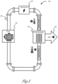
- FIG. 1 shows a schematic view of an example thermal management system 100 known to the art.
- a thermal load or heat source 110 for example an electronic device, generates excess heat.
- Coolant typically a fluid i.e. liquid or gas, is used to reduce or regulate the temperature of the system 100 and the heat source 110.
- the coolant used has high thermal capacity so as to be able to absorb and transfer large amounts of thermal energy from the heat source 110.
- a common example of a coolant is water.
- Other examples include water-glycol and oil-based fluids.
- a coolant may maintain its state of matter (e.g. stay liquid or gas) during the cooling process, or the coolant can undergo a phase transition, i.e.
- Latent heat is thermal energy which allows a substance, e.g. the coolant, to change state without changing the temperature of the substance.
- "sensible heat” involves an energy transfer that results in a temperature change of the system, and is the most common form of heat storage.
- the coolant is water
- transferring heat from a heat source may cause the initially liquid coolant to transition into a gas, i.e. steam.
- coolant is transferred around the closed-loop system 100 along coolant pipes 105 by a pump 130.
- the coolant flows past or through the heat source 110, which in the example shown is an electronic device.
- the coolant extracts/absorbs thermal energy from the device 110, cooling the device 110, and subsequently the coolant carries the thermal energy away from the device 110 to the heat exchanger 120.
- the heat exchanger 120 extracts the thermal energy from the coolant, and the coolant exits the heat exchanger 120 as cooled fluid, whilst the thermal energy is transferred to a heat dump, i.e. expelled through an exhaust 125.
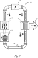
- FIG. 2 shows an example of a thermal management system 200 adapted to control the temperature of a heat source 210, such as an electronic device.
- a heat source 210 such as an electronic device.
- excess heat is generated.
- Coolant is pumped around the closed-loop system 200 though a system of coolant pipes 205 by a pump 230.
- the coolant flows past, around or through the electronic device 210 and extracts/absorbs thermal energy from the device 210.
- the thermal energy generated by the device 210 is transferred away in the (heated) fluid coolant to a heat exchanger 220, thus cooling the device 210.
- the cooling pipes 205 may be surrounded by, abutted to or placed near the heat exchanger 220 to allow the thermal energy gathered as the cooling fluid passed the heat source 210, to be transferred away from the fluid coolant (thus cooling the fluid coolant).
- the heat exchanger 220 expels the extracted thermal energy through an exhaust 225.
- the (cooled) fluid coolant exits the heat exchanger 220 ready to be pumped back round the closed loop system 200 to the device 210 again.
- the fluid coolant may be pumped to a different cooling system.
- coolants can be used to help reduce or regulate the temperate of a device.
- the effectiveness of a coolant e.g. its ability to absorb/transmit thermal energy, is influenced by the temperature of the coolant itself and therefore it is also important to maintain the coolant within an optimal temperature range so as to achieve efficient cooling of a heat source. If the coolant is too hot, or too cold, the thermal conductivity is reduced, thus decreasing the coolant's ability to absorb thermal energy from a heat source, and the device being cooled may overheat.
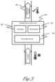
- the thermal management system 200 also comprises a temperature control unit (TCU) 250.
- the TCU 250 is located on the closed loop at a position after the heat exchanger 220 and before the heat source 210, e.g. an electric device.
- the TCU 250 comprises a temperature monitoring device 252 (e.g. a thermometer), a controller 256, and a TCU heat source 254.
- the coolant is cooled by the heat exchanger 220 to a temperature deliberately below the optimal temperature for the coolant.
- the coolant is pumped around the system 200 through the coolant pipes 205, and the coolant enters the TCU 250, the TCU measures the coolant temperature with the temperature monitoring device 252. If the coolant temperature is below the optimal operational temperature for the coolant, the controller 256 activates the TCU heat source 252 to heat up the coolant to the desired temperature, i.e. the optimal temperature for cooling the electronic device 210. It is easier to heat the coolant to a desired temperature, i.e. the optimal temperature for cooling the electronic device 210, than it would be to cool it down to the desired temperature. Therefore the coolant temperature can be more finely controlled, and the efficiency of the thermal management system 200 is improved. Accurate control of the temperature of the coolant is also important when the coolant incorporates phase change materials, as described in more detail below.
- the thermal management system incorporates a phase change material (PCM).
- PCMs melt and solidify (i.e. change state) at a certain temperature, and are capable of: storing thermal energy as the PCM transforms from a solid to a liquid state; and releasing energy as the PCM transforms from a liquid to a solid state.
- PCMs store latent heat, i.e. thermal energy released or absorbed during a constant-temperature process, e.g. such as a first-order phase transition.
- Latent heat is thermal energy which allows the change of state of a substance without changing its temperature.
- "sensible heat” involves a thermal energy transfer that results in a temperature change of the system, and is the most common form of heat storage.
- PCMS examples include ice/water (which melts/solidifies at 0°C), wax (e.g. paraffin wax) and salt hydrides (also known as ionic or saline hydrides).
- Waxes can be formulated with a range of melting points (approximately between -10°C and +90°C).
- Figure 4a is a graph showing the relationship between the temperature of a sensible heat storage material and the thermal energy supplied to it. Any thermal energy transferred to the sensible heat storage medium results in a temperature increase of the storage medium.
- An example of a sensible heat storage medium is water, wherein transferring thermal energy to water results in the temperature of the water increasing. Transferring thermal energy away from water would result in the water cooling.
- Figure 4b is a graph showing the relationship between the temperature of a latent heat storage material, such as a PCM, and the thermal energy supplied to it.
- a latent heat storage material such as a PCM
- point LH1 melting/freezing temperature
- the PCM experiences a change in state from a solid to a liquid.
- the MP of the PCM is approximately 10°C to 40°C.
- PCMs are incorporated into the fluid coolant, wherein the coolant comprises a carrier fluid.
- the carrier fluid may be water based (e.g. water, or water glycol (ethylene or propylene)) or oil based (e.g. polyalphaolefin (PA0) or silicate esters).
- PCM particles or capsules are suspended in the carrier fluid. In some examples, the particles are each approximately 1 - 50 ⁇ m diameter. The preferable size range may be limited due to stability thresholds encountered during the standard production process.
- the carrier fluid works with the PCMs to provide enhanced heat transfer capabilities of the resulting coolant when compared to a simple fluid alone, since the latent heat storage of the PCM allows the coolant to extract, store and more thermal energy from a heat source.
- the PCM may be encapsulated in an outer resin or shell to ensure that the PCM maintains its shape and/or location during its change of state.
- encapsulating materials include thermosetting plastics, such as melamine formaldehyde (MF) or polyurethane (PU).
- encapsulated PCMs are suspended in a carrier fluid, and free to flow without confinement throughout the coolant pipes 205 of a thermal management system, such as that shown in Figure 2 .
- Both the suspended PCM and carrier fluid absorb thermal energy directly from the heat source 210, increasing the cooling effect compared to a simple fluid coolant alone.
- the effectiveness of a PCM to absorb/transmit thermal energy is influenced by the temperature of the PCM. In order to maximise the thermal efficiency of the PCM to absorb thermal energy, it is important to maintain the PCM within an optimal temperature range, preferably just below the melting point of the PCM (e.g.
- the PCM-laced coolant may be cooled by a heat exchanger 220 to below the optimal operational temperature for thermal absorption (e.g. well below the MP of the PCM). The PCM-laced coolant may then be brought back up to an optimal temperature by a TCU 250 so as to provide optimal thermal extraction from a heat source 210.
- Figure 5a shows an example of an encapsulated PCM 310 suspended in a carrier fluid 330 within a coolant pipe 305.
- the coolant pipe 305 could be a cooling tank, or other storage container or conduit suitable for thermal energy transfer.
- the encapsulated PCM 310 is confined by at least one porous mesh or membrane 320 that allows the fluid 330 to pass through or along the coolant pipe 305, but retains the particles 310 in a "PCM containment zone". In other words, the PCM particles are not able to pass through the membrane/mesh, but the fluid coolant 330 is.
- the fluid 300 enters the PCM containment zone carrying thermal energy.
- the thermal energy is transferred to the encapsulated PCM particles 310 as the fluid 330 passes through, and the cooled coolant exits the PCM containment zone.
- the membrane or mesh 320 ensure that the PCM particles 310 are contained within a predetermined space within the coolant pipe 305, and the fluid 330 may flow freely through.
- the PCM particles 310 absorb the thermal energy contained in the fluid 330 by changing state from solid to liquid, within the encapsulation shell. The thermal energy is then expelled from the heat exchanger to an exhaust.
- Figure 5b shows another example of a heat exchanger arrangement 350, wherein at least one encapsulated PCM is incorporated into a porous mesh, membrane, matrix of cavities, or foam 360 material.
- the porous mesh, membrane, matrix of cavities, or foam 360 is a polymer, such as polyester, polyether, or polyurethane, or a metal, such as aluminium, an alloy of aluminium, titanium, or steel.
- the coolant 380 is channelled via piping 355 through the PCM porous mesh, membrane, matrix of cavities, or foam 360, transferring thermal energy to the PCM suspended in the material, which is then expelled from the heat exchanger to an exhaust. The cooled coolant 380 then exits the heat exchanger 350.
- the thermal management system is coupled to a wider fuel system for another device, and the fluid coolant pumped around the system may be a fuel for the other device.
- the fluid coolant pumped around the system may be a fuel for the other device.
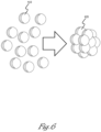
- the encapsulated PCM particles 410 may be combined or incorporated into a polynuclear PCM, or PCM "molecule" 420.
- the resultant PCM molecule 420 is larger than a standard (single) particle, thus allowing for a coarser mesh or membrane 320 to be used in restraining the PCM within the carrier flow.
- the polynuclear particles have a diameter in the 0.5 - 5 mm diameter range, allowing for a mesh with an example gap size of up to 0.4 - 4mm in size (depending on the polynuclear particle size).
- the coarser mesh or membrane 320 provides less resistance to the coolant flow, and a smaller pump required in order to achieve the same rate of flow.
- the polynuclear PCM is formed through flocculation.
- the individual PCM particles may be bonded together by forming them into dies.
- the different types of heat exchanger as described above may be combined, e.g. comprising both a porous mesh 320 or membrane to constrain suspended encapsulated PCM particles 310, and a porous mesh, membrane, matrix of cavities, or foam 360 comprising encapsulated PCM, through which the fluid coolant 300 may flow.
- the fluid coolant 300 may comprise suspended PCM particles small enough to pass through the membrane or mesh etc. within the heat exchanger, wherein larger PCM particles (e.g. a polynuclear PCM) incorporated within the heat exchanger are contained.
- the encapsulated PCM incorporated either in the heat exchanger, or within the carrier fluid as suspended particles may comprise a blend or range of different PCMs of varying melting points.
- a single encapsulated particle comprises a single PCM having a set MP. Different particles within the suspended particles or incorporated into the heat exchanger may have different MPs to other encapsulated PCMs.
- a single encapsulated particle PCM particle may comprise a mix of PCMs within a single particle.
- a blend or range of PCMs incorporated into the heat exchanger or suspended in the carrier fluid provides the opportunity to customise the thermal response of the PCM, i.e. the heat capacity profile.
- the different PCMs may be incorporated into a polynuclear PCM molecule 420, or individually within any of the examples outlined above, e.g. free flowing suspended particles, or incorporated into a mesh, membrane or matrix.
- the blend of PCMs provide a customised response to the thermal energy transfer and can be used to provide feedback about how much latent thermal capacity is left, e.g. providing warning levels.
- Figure 7 is a graph showing the relationship between the temperature of an example blended PCM material and the thermal energy supplied to it.
- the temperature increases until the blended PCM reaches its first melting/freezing temperature (MP1).
- MP1 first melting/freezing temperature
- the volume of the PCM with the lowest melting point experiences a change in state from a solid to a liquid, during which the temperature of the blended PCM does not increase and remains at the first melting point (MP1), between points LH1 and LH2.
- MP1 first melting/freezing temperature
- Figure 8 shows a flowchart of an example method 500 to be carried out in conjunction with the temperature control system 200 as described above.
- a coolant may be cooled by a heat exchanger to below the optimal operational temperature for thermal absorption (e.g. well below the MP of a PCM in a PCM-laced coolant).
- the fluid coolant is (pre)heated (from below a desired temperature) to a pre-determined temperature - i.e. the desired temperature for optimal thermal energy transfer from a heat source.
- the fluid coolant is pumped to a heat source, and at step 503 the fluid coolant extracts/transfers thermal energy from the heat source.
- FIG 9 shows a flowchart of another example method 550, incorporating the steps of the method 500 shown in Figure 8 .
- the method 550 further comprises pumping the fluid coolant from the heat source to a heat exchanger at step 554.
- the thermal energy is transferred from the fluid coolant to a heat dump (i.e. an exhaust) at step 555, and where possible, it is desirable to reduce the heat of the fluid coolant to below that of the desired level, i.e. the optimal temperature for cooling.
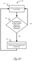
- the fluid coolant is then pumped from the heat exchanger to a temperature control unit at step 557. Whether the fluid coolant is subsequently re-heated to a desired pre-determined temperature by the temperature control unit, or is pumped straight to the heat source, is determined in step 600, as shown in Figure 10 .
- the temperature monitoring device measures the temperature of the fluid coolant.
- the controller determines whether the fluid coolant temperature is above or below a pre-determined threshold temperature at step 602. If the fluid coolant is above a pre-determined threshold temperature, i.e. at the optimal temperature or above, then the fluid coolant is pumped onto the heat source. If the fluid coolant is below the optimal temperature then at step 603 the controller activates a heat source in the TCU to heat the fluid coolant up to the desired (i.e. optimal temperature).
- the fluid coolant comprises a PCM, as encapsulated particles suspended in a carrier fluid, then the desired temperature for the fluid coolant is just below the melting point of the PCM. If there is a blend of multiple PCMs in the fluid coolant, then the desired temperature is just below the lowest melting point of the blend of PCMs
- the threshold temperature below which the TCU activates the TCU heat source to heat the fluid coolant is a different value to the desired temperature of the fluid coolant.
- the fluid coolant having green pumped from one heat source, to a heat exchanger and a TCU, may be pumped through a different heat source subsequently.
- the heat source is a high-load electrical device that is only operational for short bursts, and requires down-time between operating cycles.
- the electrical device requires efficient cooling to counter the generation of a large amount of thermal energy in a very short amount of time.
- the thermal management system must keep the electrical device cool during its short operational burst, and the thermal energy can be expelled in the periods between the operational bursts of the electrical device.
Landscapes
- Engineering & Computer Science (AREA)
- General Engineering & Computer Science (AREA)
- Mechanical Engineering (AREA)
- Physics & Mathematics (AREA)
- Thermal Sciences (AREA)
- Chemical & Material Sciences (AREA)
- Dispersion Chemistry (AREA)
- Theoretical Computer Science (AREA)
- Human Computer Interaction (AREA)
- General Physics & Mathematics (AREA)
- Microelectronics & Electronic Packaging (AREA)
- Life Sciences & Earth Sciences (AREA)
- Sustainable Development (AREA)
- Cooling Or The Like Of Electrical Apparatus (AREA)
Claims (11)
- Wärmemanagementsystem (200) für eine Wärmequelle (210), das System umfassend einen geschlossenen Kreislauf:ein flüssiges Kühlmittel zum Entziehen von thermischer Energie aus der Wärmequelle,eine Pumpe (230) zum Pumpen des flüssigen Kühlmittels in dem System herum;einen Wärmetauscher (220) zum Entziehen von Wärmeenergie aus dem flüssigen Kühlmittel; undeine Temperatursteuereinheit (TCU) (250) an dem geschlossenen Kreislauf, wobei sich die TCU hinter dem Wärmetauscher und vor der Wärmequelle befindet, wobei die TCU darauf abgestimmt ist, das flüssige Kühlmittel auf eine vorherbestimmte Temperatur zu erwärmen,dadurch gekennzeichnet, dass das flüssige Kühlmittel umfasst: eine Trägerflüssigkeit (330); und eingekapselte Phasenwechselmaterialpartikel (PCM-Partikel) (310), die in der Trägerflüssigkeit suspendiert sind.
- Wärmemanagementsystem nach Anspruch 1, die TCU umfassend:ein Thermometer (252);eine TCU-Wärmequelle (254); undeiner Steuerung (256),wobei die Steuerung die TCU-Wärmequelle aktiviert und das flüssige Kühlmittel auf eine vorherbestimmte Temperatur erwärmt, falls die durch das Thermometer gemessene Kühlmitteltemperatur unter einer vorherbestimmten Schwelle liegt.
- Wärmemanagementsystem nach Anspruch 1, wobei:
die vorherbestimmte Temperatur, auf die die TCU abgestimmt ist, um das flüssige Kühlmittel zu erwärmen, unter dem Schmelzpunkt des PCM liegt. - Wärmemanagementsystem nach einem der vorstehenden Ansprüche, wobei der Wärmetauscher umfasst:eingekapselte PCM-Partikel, die in dem Kühlmittelstrom suspendiert sind; undein poröses Netz (320),wobei die Größe der porösen Netzlücke kleiner als die PCM-Partikelgröße ist, wobei die PCM-Partikel in einem Eindämmungsbereich gehalten werden, aber durch den das flüssige Kühlmittel durchfließen kann.
- Wärmemanagementsystem nach Anspruch 4, wobei:
das eingekapselte PCM aus zwei oder mehr miteinander kombinierten PCM-Partikeln (420) ausgebildet ist. - Wärmemanagementsystem nach einem der vorstehenden Ansprüche, wobei der Wärmetauscher umfasst:
einen porösen Schaum (360), eine Matrix aus Rohrhohlräumen oder ein Netz, das die eingekapselten PCM-Partikel enthält. - Wärmemanagementsystem nach einem der vorstehenden Ansprüche, wobei:
mehr als ein PCM-Typ verwendet werden kann, wobei jeder PCM-Typ einen unterschiedlichen Schmelzpunkt aufweist. - Wärmemanagementsystem nach einem der vorstehenden Ansprüche, wobei:das Wärmemanagementsystem mit einem erweiterten Kraftstoffsystem für eine andere Vorrichtung gekoppelt ist; unddas flüssige Kühlmittel eine Kraftstoffquelle für die andere Vorrichtung ist.
- Verfahren zum Wärmemanagement einer Wärmequelle in einem System, umfassend einen geschlossenen Kreislauf, das Verfahren umfassend:
Vorwärmen eines flüssigen Kühlmittels auf eine vorherbestimmte Temperatur, wobei das flüssige Kühlmittel umfasst:eine Trägerflüssigkeit (330); undeingekapselte Phasenwechselmaterialpartikel (PCM-Partikel) (310), die in der Trägerflüssigkeit suspendiert sind;Pumpen des flüssigen Kühlmittels zu der Wärmequelle;Entziehen von Wärmeenergie aus der Wärmequelle zu dem flüssigen Kühlmittel;Pumpen des flüssigen Kühlmittels von der Wärmequelle zu einem Wärmetauscher;Übertragen von Wärmeenergie von dem flüssigen Kühlmittel über den Wärmetauscher zu einer Wärmeabfuhr; undPumpen des flüssigen Kühlmittels von dem Wärmetauscher zu einer Temperatursteuereinheit (TCU), wobei sich die TCU hinter dem Wärmetauscher und vor der Wärmequelle in dem geschlossenen Kreislauf befindet. - Verfahren nach Anspruch 9, wobei:
ein Übertragen von Wärmeenergie aus dem flüssigen Kühlmittel bewirkt, dass sich dieses auf unter die vorherbestimmte Temperatur abkühlt. - Verfahren nach einem der Ansprüche 9 bis 10, wobei das Verfahren ferner umfasst:Messen der Temperatur des flüssigen Kühlmittels; undfalls die Temperatur des flüssigen Kühlmittels unter einer vorherbestimmten Schwelle liegt, dann Aktivieren einer Wärmequelle, um das flüssige Kühlmittel auf eine vorherbestimmte Temperatur zu erwärmen.
Applications Claiming Priority (2)
| Application Number | Priority Date | Filing Date | Title |
|---|---|---|---|
| GB1811860.4A GB2575680B (en) | 2018-07-20 | 2018-07-20 | Thermal management system |
| PCT/GB2019/052028 WO2020016598A1 (en) | 2018-07-20 | 2019-07-19 | Thermal management system |
Publications (3)
| Publication Number | Publication Date |
|---|---|
| EP3824239A1 EP3824239A1 (de) | 2021-05-26 |
| EP3824239B1 true EP3824239B1 (de) | 2025-01-29 |
| EP3824239C0 EP3824239C0 (de) | 2025-01-29 |
Family
ID=63364318
Family Applications (1)
| Application Number | Title | Priority Date | Filing Date |
|---|---|---|---|
| EP19745238.6A Active EP3824239B1 (de) | 2018-07-20 | 2019-07-19 | Wärmeverwaltungssystem |
Country Status (7)
| Country | Link |
|---|---|
| US (1) | US20210262739A1 (de) |
| EP (1) | EP3824239B1 (de) |
| AU (1) | AU2019306775B2 (de) |
| CA (1) | CA3106902A1 (de) |
| ES (1) | ES3016808T3 (de) |
| GB (1) | GB2575680B (de) |
| WO (1) | WO2020016598A1 (de) |
Families Citing this family (6)
| Publication number | Priority date | Publication date | Assignee | Title |
|---|---|---|---|---|
| GB2575679B (en) | 2018-07-20 | 2022-06-15 | Bae Systems Plc | Thermal Management System |
| EP4068930B1 (de) | 2021-04-01 | 2024-03-13 | Ovh | Racksystem zur aufnahme einer elektronischen vorrichtung |
| US11729950B2 (en) | 2021-04-01 | 2023-08-15 | Ovh | Immersion cooling system with dual dielectric cooling liquid circulation |
| CA3153037A1 (en) | 2021-04-01 | 2022-10-01 | Ovh | Hybrid immersion cooling system for rack-mounted electronic assemblies |
| EP4068928B1 (de) | 2021-04-01 | 2024-01-31 | Ovh | Kühlvorrichtung |
| CA3152605A1 (en) | 2021-04-01 | 2022-10-01 | Ovh | Systems and methods for autonomously activable redundant cooling of a heat generating component |
Citations (3)
| Publication number | Priority date | Publication date | Assignee | Title |
|---|---|---|---|---|
| WO2004009728A1 (en) * | 2002-07-24 | 2004-01-29 | Daimlerchrysler Corporation | Multi-phase suspension coolant |
| US20170127563A1 (en) * | 2015-10-28 | 2017-05-04 | International Business Machines Corporation | Cooling systems for cooling electronic components |
| CN107421030A (zh) * | 2017-07-21 | 2017-12-01 | 武汉大学 | 一种基于相变微胶囊液浆储冷装置的冷却系统及运行方法 |
Family Cites Families (19)
| Publication number | Priority date | Publication date | Assignee | Title |
|---|---|---|---|---|
| SE301905B (de) * | 1962-12-21 | 1968-06-24 | Separator Ab | |
| DE1941062C3 (de) * | 1968-09-09 | 1975-10-30 | Thermo-Bauelement Ag, Murten (Schweiz) | Speicherwärmetauscher |
| US3943325A (en) * | 1973-01-05 | 1976-03-09 | Bardon Research And Development Limited | Engine preheater |
| US3848416A (en) * | 1973-05-23 | 1974-11-19 | Gen Electric | Power generating plant with nuclear reactor/heat storage system combination |
| US4193271A (en) * | 1977-07-07 | 1980-03-18 | Honigsbaum Richard F | Air conditioning system having controllably coupled thermal storage capability |
| US4807696A (en) * | 1987-12-10 | 1989-02-28 | Triangle Research And Development Corp. | Thermal energy storage apparatus using encapsulated phase change material |
| US5687706A (en) * | 1995-04-25 | 1997-11-18 | University Of Florida | Phase change material storage heater |
| US6447692B1 (en) * | 2000-08-04 | 2002-09-10 | Hrl Laboratories, Llc | Nanometer sized phase change materials for enhanced heat transfer fluid performance |
| JP2004353602A (ja) * | 2003-05-30 | 2004-12-16 | Nippon Thermostat Co Ltd | 電子制御サーモスタットの制御方法 |
| US20090211732A1 (en) * | 2008-02-21 | 2009-08-27 | Lakhi Nandlal Goenka | Thermal energy exchanger for a heating, ventilating, and air conditioning system |
| DE102008013657A1 (de) * | 2008-03-11 | 2009-09-17 | Daimler Ag | Brennkraftmaschine mit Wärmespeicher |
| US9557120B2 (en) * | 2012-10-10 | 2017-01-31 | Promethean Power Systems, Inc. | Thermal energy battery with enhanced heat exchange capability and modularity |
| ES2480765B1 (es) * | 2012-12-27 | 2015-05-08 | Universitat Politècnica De Catalunya | Sistema de almacenamiento de energía térmica combinando material sólido de calor sensible y material de cambio de fase |
| JP6169403B2 (ja) * | 2013-04-26 | 2017-07-26 | 株式会社日立製作所 | 鉄道車両用駆動システム及びこれを搭載した鉄道車両 |
| US9759114B2 (en) * | 2014-06-17 | 2017-09-12 | Ford Global Technologies, Llc | Selective powertrain heating system |
| WO2016050365A1 (en) * | 2014-09-30 | 2016-04-07 | Siemens Aktiengesellschaft | High temperature thermal energy exchange system with horizontal heat exchange chamber and method for exchanging thermal energy |
| NO339952B1 (no) * | 2014-12-19 | 2017-02-20 | Energynest As | Termisk energilager og varmeveklser |
| US10424821B2 (en) * | 2017-04-03 | 2019-09-24 | Yotta Solar, Inc. | Thermally regulated modular energy storage device and methods |
| CN108336445A (zh) * | 2017-12-20 | 2018-07-27 | 北京长城华冠汽车科技股份有限公司 | 电池包热管理系统及电池包 |
-
2018
- 2018-07-20 GB GB1811860.4A patent/GB2575680B/en active Active
-
2019
- 2019-07-19 CA CA3106902A patent/CA3106902A1/en active Pending
- 2019-07-19 WO PCT/GB2019/052028 patent/WO2020016598A1/en not_active Ceased
- 2019-07-19 AU AU2019306775A patent/AU2019306775B2/en active Active
- 2019-07-19 EP EP19745238.6A patent/EP3824239B1/de active Active
- 2019-07-19 ES ES19745238T patent/ES3016808T3/es active Active
- 2019-07-19 US US17/261,714 patent/US20210262739A1/en not_active Abandoned
Patent Citations (3)
| Publication number | Priority date | Publication date | Assignee | Title |
|---|---|---|---|---|
| WO2004009728A1 (en) * | 2002-07-24 | 2004-01-29 | Daimlerchrysler Corporation | Multi-phase suspension coolant |
| US20170127563A1 (en) * | 2015-10-28 | 2017-05-04 | International Business Machines Corporation | Cooling systems for cooling electronic components |
| CN107421030A (zh) * | 2017-07-21 | 2017-12-01 | 武汉大学 | 一种基于相变微胶囊液浆储冷装置的冷却系统及运行方法 |
Also Published As
| Publication number | Publication date |
|---|---|
| WO2020016598A1 (en) | 2020-01-23 |
| GB201811860D0 (en) | 2018-09-05 |
| ES3016808T3 (en) | 2025-05-09 |
| GB2575680A (en) | 2020-01-22 |
| AU2019306775B2 (en) | 2024-11-07 |
| CA3106902A1 (en) | 2020-01-23 |
| GB2575680B (en) | 2022-07-13 |
| AU2019306775A1 (en) | 2021-02-11 |
| EP3824239A1 (de) | 2021-05-26 |
| EP3824239C0 (de) | 2025-01-29 |
| US20210262739A1 (en) | 2021-08-26 |
Similar Documents
| Publication | Publication Date | Title |
|---|---|---|
| EP3824239B1 (de) | Wärmeverwaltungssystem | |
| US20230328926A1 (en) | Thermal management system | |
| US11357130B2 (en) | Scalable thermal ride-through for immersion-cooled server systems | |
| EP4068048B1 (de) | Systeme und verfahren zur autonom aktivierbaren redundanten kühlung einer wärmeerzeugungskomponente | |
| US20160006088A1 (en) | Battery thermal management for hybrid electric vehicles using a phase-change material cold plate | |
| CN115209684A (zh) | 冷却系统 | |
| JP6542034B2 (ja) | Pcmを用いて機器部品を冷却するための装置 | |
| US20040019123A1 (en) | Multi-phase suspension coolant | |
| CN112261841A (zh) | 基于相变胶囊储热控温的电子设备冷却供液系统及方法 | |
| EP2916092A1 (de) | Vorrichtung und verfahren zur wärmeenergierückgewinnung | |
| US11407076B2 (en) | Regeneration device for regenerating a coolant dispersion | |
| GB2603082A (en) | Thermal management system | |
| US10330394B2 (en) | Heat transfer mediums | |
| Zahid et al. | Phase change materials (PCMs) | |
| CN117042420B (zh) | 一种带有糖醇类pcm储能单元的电子设备散热系统及方法 | |
| Nallusamy et al. | Experimental investigation on heat transfer enhancement of latent heat storage system containing spherical capsules with internal hollow and solid fins | |
| US20240291232A1 (en) | Multi-fluid heat exchanger for a laser system | |
| Nivaskarthick | Analysis of Thermal Energy Storage system using Paraffin Wax as Phase Change Material | |
| Wilson et al. | High power thermal energy storage from ordered-pore additively manufactured phase-transforming nickel-titanium porous cubes | |
| Sobhansarbandi et al. | Melting process expedition of phase change materials via silicone oil | |
| Anish et al. | Experimental Analysis of Spiral Finned Tube Heat Exchanger Using PCM as Thermal Energy Storage | |
| Karunamurthy et al. | PCM based thermal energy storage system containing CuO nano-particles | |
| CN121054862A (zh) | 新能源重卡汽车电池组、热管理机组及方法 | |
| Ulitenko et al. | A System for Stabilizing the Temperature of the Shells of High-Power Electronic Devices |
Legal Events
| Date | Code | Title | Description |
|---|---|---|---|
| STAA | Information on the status of an ep patent application or granted ep patent |
Free format text: STATUS: UNKNOWN |
|
| STAA | Information on the status of an ep patent application or granted ep patent |
Free format text: STATUS: THE INTERNATIONAL PUBLICATION HAS BEEN MADE |
|
| PUAI | Public reference made under article 153(3) epc to a published international application that has entered the european phase |
Free format text: ORIGINAL CODE: 0009012 |
|
| STAA | Information on the status of an ep patent application or granted ep patent |
Free format text: STATUS: REQUEST FOR EXAMINATION WAS MADE |
|
| 17P | Request for examination filed |
Effective date: 20210129 |
|
| AK | Designated contracting states |
Kind code of ref document: A1 Designated state(s): AL AT BE BG CH CY CZ DE DK EE ES FI FR GB GR HR HU IE IS IT LI LT LU LV MC MK MT NL NO PL PT RO RS SE SI SK SM TR |
|
| DAV | Request for validation of the european patent (deleted) | ||
| DAX | Request for extension of the european patent (deleted) | ||
| STAA | Information on the status of an ep patent application or granted ep patent |
Free format text: STATUS: EXAMINATION IS IN PROGRESS |
|
| 17Q | First examination report despatched |
Effective date: 20230426 |
|
| GRAP | Despatch of communication of intention to grant a patent |
Free format text: ORIGINAL CODE: EPIDOSNIGR1 |
|
| STAA | Information on the status of an ep patent application or granted ep patent |
Free format text: STATUS: GRANT OF PATENT IS INTENDED |
|
| INTG | Intention to grant announced |
Effective date: 20241025 |
|
| GRAS | Grant fee paid |
Free format text: ORIGINAL CODE: EPIDOSNIGR3 |
|
| GRAA | (expected) grant |
Free format text: ORIGINAL CODE: 0009210 |
|
| STAA | Information on the status of an ep patent application or granted ep patent |
Free format text: STATUS: THE PATENT HAS BEEN GRANTED |
|
| AK | Designated contracting states |
Kind code of ref document: B1 Designated state(s): AL AT BE BG CH CY CZ DE DK EE ES FI FR GB GR HR HU IE IS IT LI LT LU LV MC MK MT NL NO PL PT RO RS SE SI SK SM TR |
|
| REG | Reference to a national code |
Ref country code: GB Ref legal event code: FG4D |
|
| REG | Reference to a national code |
Ref country code: CH Ref legal event code: EP |
|
| REG | Reference to a national code |
Ref country code: DE Ref legal event code: R096 Ref document number: 602019065399 Country of ref document: DE |
|
| REG | Reference to a national code |
Ref country code: IE Ref legal event code: FG4D |
|
| U01 | Request for unitary effect filed |
Effective date: 20250226 |
|
| U07 | Unitary effect registered |
Designated state(s): AT BE BG DE DK EE FI FR IT LT LU LV MT NL PT RO SE SI Effective date: 20250305 |
|
| REG | Reference to a national code |
Ref country code: ES Ref legal event code: FG2A Ref document number: 3016808 Country of ref document: ES Kind code of ref document: T3 Effective date: 20250509 |
|
| PG25 | Lapsed in a contracting state [announced via postgrant information from national office to epo] |
Ref country code: RS Free format text: LAPSE BECAUSE OF FAILURE TO SUBMIT A TRANSLATION OF THE DESCRIPTION OR TO PAY THE FEE WITHIN THE PRESCRIBED TIME-LIMIT Effective date: 20250429 |
|
| PG25 | Lapsed in a contracting state [announced via postgrant information from national office to epo] |
Ref country code: PL Free format text: LAPSE BECAUSE OF FAILURE TO SUBMIT A TRANSLATION OF THE DESCRIPTION OR TO PAY THE FEE WITHIN THE PRESCRIBED TIME-LIMIT Effective date: 20250129 |
|
| PGFP | Annual fee paid to national office [announced via postgrant information from national office to epo] |
Ref country code: GB Payment date: 20250619 Year of fee payment: 7 |
|
| PG25 | Lapsed in a contracting state [announced via postgrant information from national office to epo] |
Ref country code: NO Free format text: LAPSE BECAUSE OF FAILURE TO SUBMIT A TRANSLATION OF THE DESCRIPTION OR TO PAY THE FEE WITHIN THE PRESCRIBED TIME-LIMIT Effective date: 20250429 Ref country code: IS Free format text: LAPSE BECAUSE OF FAILURE TO SUBMIT A TRANSLATION OF THE DESCRIPTION OR TO PAY THE FEE WITHIN THE PRESCRIBED TIME-LIMIT Effective date: 20250529 |
|
| PG25 | Lapsed in a contracting state [announced via postgrant information from national office to epo] |
Ref country code: HR Free format text: LAPSE BECAUSE OF FAILURE TO SUBMIT A TRANSLATION OF THE DESCRIPTION OR TO PAY THE FEE WITHIN THE PRESCRIBED TIME-LIMIT Effective date: 20250129 |
|
| PG25 | Lapsed in a contracting state [announced via postgrant information from national office to epo] |
Ref country code: GR Free format text: LAPSE BECAUSE OF FAILURE TO SUBMIT A TRANSLATION OF THE DESCRIPTION OR TO PAY THE FEE WITHIN THE PRESCRIBED TIME-LIMIT Effective date: 20250430 |
|
| U20 | Renewal fee for the european patent with unitary effect paid |
Year of fee payment: 7 Effective date: 20250620 |
|
| PG25 | Lapsed in a contracting state [announced via postgrant information from national office to epo] |
Ref country code: SM Free format text: LAPSE BECAUSE OF FAILURE TO SUBMIT A TRANSLATION OF THE DESCRIPTION OR TO PAY THE FEE WITHIN THE PRESCRIBED TIME-LIMIT Effective date: 20250129 |
|
| PGFP | Annual fee paid to national office [announced via postgrant information from national office to epo] |
Ref country code: ES Payment date: 20250801 Year of fee payment: 7 |
|
| PG25 | Lapsed in a contracting state [announced via postgrant information from national office to epo] |
Ref country code: CZ Free format text: LAPSE BECAUSE OF FAILURE TO SUBMIT A TRANSLATION OF THE DESCRIPTION OR TO PAY THE FEE WITHIN THE PRESCRIBED TIME-LIMIT Effective date: 20250129 |
|
| PG25 | Lapsed in a contracting state [announced via postgrant information from national office to epo] |
Ref country code: SK Free format text: LAPSE BECAUSE OF FAILURE TO SUBMIT A TRANSLATION OF THE DESCRIPTION OR TO PAY THE FEE WITHIN THE PRESCRIBED TIME-LIMIT Effective date: 20250129 |