EP3823815B1 - Verfahren und vorrichtung zur herstellung einer durchsteckverbindung mehrerer kabel oder schläuchen durch ein kunststoffbauteil - Google Patents
Verfahren und vorrichtung zur herstellung einer durchsteckverbindung mehrerer kabel oder schläuchen durch ein kunststoffbauteil Download PDFInfo
- Publication number
- EP3823815B1 EP3823815B1 EP19729253.5A EP19729253A EP3823815B1 EP 3823815 B1 EP3823815 B1 EP 3823815B1 EP 19729253 A EP19729253 A EP 19729253A EP 3823815 B1 EP3823815 B1 EP 3823815B1
- Authority
- EP
- European Patent Office
- Prior art keywords
- plastic component
- laser beam
- plastic
- openings
- connection
- Prior art date
- Legal status (The legal status is an assumption and is not a legal conclusion. Google has not performed a legal analysis and makes no representation as to the accuracy of the status listed.)
- Active
Links
Images


Classifications
-
- B—PERFORMING OPERATIONS; TRANSPORTING
- B29—WORKING OF PLASTICS; WORKING OF SUBSTANCES IN A PLASTIC STATE IN GENERAL
- B29C—SHAPING OR JOINING OF PLASTICS; SHAPING OF MATERIAL IN A PLASTIC STATE, NOT OTHERWISE PROVIDED FOR; AFTER-TREATMENT OF THE SHAPED PRODUCTS, e.g. REPAIRING
- B29C65/00—Joining or sealing of preformed parts, e.g. welding of plastics materials; Apparatus therefor
- B29C65/02—Joining or sealing of preformed parts, e.g. welding of plastics materials; Apparatus therefor by heating, with or without pressure
- B29C65/14—Joining or sealing of preformed parts, e.g. welding of plastics materials; Apparatus therefor by heating, with or without pressure using wave energy, i.e. electromagnetic radiation, or particle radiation
- B29C65/16—Laser beams
- B29C65/1629—Laser beams characterised by the way of heating the interface
- B29C65/1635—Laser beams characterised by the way of heating the interface at least passing through one of the parts to be joined, i.e. laser transmission welding
-
- B—PERFORMING OPERATIONS; TRANSPORTING
- B29—WORKING OF PLASTICS; WORKING OF SUBSTANCES IN A PLASTIC STATE IN GENERAL
- B29C—SHAPING OR JOINING OF PLASTICS; SHAPING OF MATERIAL IN A PLASTIC STATE, NOT OTHERWISE PROVIDED FOR; AFTER-TREATMENT OF THE SHAPED PRODUCTS, e.g. REPAIRING
- B29C65/00—Joining or sealing of preformed parts, e.g. welding of plastics materials; Apparatus therefor
- B29C65/02—Joining or sealing of preformed parts, e.g. welding of plastics materials; Apparatus therefor by heating, with or without pressure
- B29C65/14—Joining or sealing of preformed parts, e.g. welding of plastics materials; Apparatus therefor by heating, with or without pressure using wave energy, i.e. electromagnetic radiation, or particle radiation
- B29C65/16—Laser beams
- B29C65/1629—Laser beams characterised by the way of heating the interface
- B29C65/1654—Laser beams characterised by the way of heating the interface scanning at least one of the parts to be joined
-
- B—PERFORMING OPERATIONS; TRANSPORTING
- B29—WORKING OF PLASTICS; WORKING OF SUBSTANCES IN A PLASTIC STATE IN GENERAL
- B29C—SHAPING OR JOINING OF PLASTICS; SHAPING OF MATERIAL IN A PLASTIC STATE, NOT OTHERWISE PROVIDED FOR; AFTER-TREATMENT OF THE SHAPED PRODUCTS, e.g. REPAIRING
- B29C65/00—Joining or sealing of preformed parts, e.g. welding of plastics materials; Apparatus therefor
- B29C65/02—Joining or sealing of preformed parts, e.g. welding of plastics materials; Apparatus therefor by heating, with or without pressure
- B29C65/14—Joining or sealing of preformed parts, e.g. welding of plastics materials; Apparatus therefor by heating, with or without pressure using wave energy, i.e. electromagnetic radiation, or particle radiation
- B29C65/16—Laser beams
- B29C65/1629—Laser beams characterised by the way of heating the interface
- B29C65/1654—Laser beams characterised by the way of heating the interface scanning at least one of the parts to be joined
- B29C65/1661—Laser beams characterised by the way of heating the interface scanning at least one of the parts to be joined scanning repeatedly, e.g. quasi-simultaneous laser welding
-
- B—PERFORMING OPERATIONS; TRANSPORTING
- B29—WORKING OF PLASTICS; WORKING OF SUBSTANCES IN A PLASTIC STATE IN GENERAL
- B29C—SHAPING OR JOINING OF PLASTICS; SHAPING OF MATERIAL IN A PLASTIC STATE, NOT OTHERWISE PROVIDED FOR; AFTER-TREATMENT OF THE SHAPED PRODUCTS, e.g. REPAIRING
- B29C65/00—Joining or sealing of preformed parts, e.g. welding of plastics materials; Apparatus therefor
- B29C65/02—Joining or sealing of preformed parts, e.g. welding of plastics materials; Apparatus therefor by heating, with or without pressure
- B29C65/14—Joining or sealing of preformed parts, e.g. welding of plastics materials; Apparatus therefor by heating, with or without pressure using wave energy, i.e. electromagnetic radiation, or particle radiation
- B29C65/16—Laser beams
- B29C65/1629—Laser beams characterised by the way of heating the interface
- B29C65/1664—Laser beams characterised by the way of heating the interface making use of several radiators
- B29C65/1667—Laser beams characterised by the way of heating the interface making use of several radiators at the same time, i.e. simultaneous laser welding
-
- B—PERFORMING OPERATIONS; TRANSPORTING
- B29—WORKING OF PLASTICS; WORKING OF SUBSTANCES IN A PLASTIC STATE IN GENERAL
- B29C—SHAPING OR JOINING OF PLASTICS; SHAPING OF MATERIAL IN A PLASTIC STATE, NOT OTHERWISE PROVIDED FOR; AFTER-TREATMENT OF THE SHAPED PRODUCTS, e.g. REPAIRING
- B29C66/00—General aspects of processes or apparatus for joining preformed parts
- B29C66/01—General aspects dealing with the joint area or with the area to be joined
- B29C66/05—Particular design of joint configurations
- B29C66/10—Particular design of joint configurations particular design of the joint cross-sections
- B29C66/11—Joint cross-sections comprising a single joint-segment, i.e. one of the parts to be joined comprising a single joint-segment in the joint cross-section
- B29C66/112—Single lapped joints
- B29C66/1122—Single lap to lap joints, i.e. overlap joints
-
- B—PERFORMING OPERATIONS; TRANSPORTING
- B29—WORKING OF PLASTICS; WORKING OF SUBSTANCES IN A PLASTIC STATE IN GENERAL
- B29C—SHAPING OR JOINING OF PLASTICS; SHAPING OF MATERIAL IN A PLASTIC STATE, NOT OTHERWISE PROVIDED FOR; AFTER-TREATMENT OF THE SHAPED PRODUCTS, e.g. REPAIRING
- B29C66/00—General aspects of processes or apparatus for joining preformed parts
- B29C66/50—General aspects of joining tubular articles; General aspects of joining long products, i.e. bars or profiled elements; General aspects of joining single elements to tubular articles, hollow articles or bars; General aspects of joining several hollow-preforms to form hollow or tubular articles
- B29C66/51—Joining tubular articles, profiled elements or bars; Joining single elements to tubular articles, hollow articles or bars; Joining several hollow-preforms to form hollow or tubular articles
- B29C66/52—Joining tubular articles, bars or profiled elements
- B29C66/522—Joining tubular articles
- B29C66/5227—Joining tubular articles for forming multi-tubular articles by longitudinally joining elementary tubular articles wall-to-wall (e.g. joining the wall of a first tubular article to the wall of a second tubular article) or for forming multilayer tubular articles
-
- B—PERFORMING OPERATIONS; TRANSPORTING
- B29—WORKING OF PLASTICS; WORKING OF SUBSTANCES IN A PLASTIC STATE IN GENERAL
- B29C—SHAPING OR JOINING OF PLASTICS; SHAPING OF MATERIAL IN A PLASTIC STATE, NOT OTHERWISE PROVIDED FOR; AFTER-TREATMENT OF THE SHAPED PRODUCTS, e.g. REPAIRING
- B29C66/00—General aspects of processes or apparatus for joining preformed parts
- B29C66/50—General aspects of joining tubular articles; General aspects of joining long products, i.e. bars or profiled elements; General aspects of joining single elements to tubular articles, hollow articles or bars; General aspects of joining several hollow-preforms to form hollow or tubular articles
- B29C66/51—Joining tubular articles, profiled elements or bars; Joining single elements to tubular articles, hollow articles or bars; Joining several hollow-preforms to form hollow or tubular articles
- B29C66/52—Joining tubular articles, bars or profiled elements
- B29C66/526—Joining bars
-
- B—PERFORMING OPERATIONS; TRANSPORTING
- B29—WORKING OF PLASTICS; WORKING OF SUBSTANCES IN A PLASTIC STATE IN GENERAL
- B29C—SHAPING OR JOINING OF PLASTICS; SHAPING OF MATERIAL IN A PLASTIC STATE, NOT OTHERWISE PROVIDED FOR; AFTER-TREATMENT OF THE SHAPED PRODUCTS, e.g. REPAIRING
- B29C66/00—General aspects of processes or apparatus for joining preformed parts
- B29C66/50—General aspects of joining tubular articles; General aspects of joining long products, i.e. bars or profiled elements; General aspects of joining single elements to tubular articles, hollow articles or bars; General aspects of joining several hollow-preforms to form hollow or tubular articles
- B29C66/51—Joining tubular articles, profiled elements or bars; Joining single elements to tubular articles, hollow articles or bars; Joining several hollow-preforms to form hollow or tubular articles
- B29C66/53—Joining single elements to tubular articles, hollow articles or bars
- B29C66/534—Joining single elements to open ends of tubular or hollow articles or to the ends of bars
-
- B—PERFORMING OPERATIONS; TRANSPORTING
- B29—WORKING OF PLASTICS; WORKING OF SUBSTANCES IN A PLASTIC STATE IN GENERAL
- B29C—SHAPING OR JOINING OF PLASTICS; SHAPING OF MATERIAL IN A PLASTIC STATE, NOT OTHERWISE PROVIDED FOR; AFTER-TREATMENT OF THE SHAPED PRODUCTS, e.g. REPAIRING
- B29C66/00—General aspects of processes or apparatus for joining preformed parts
- B29C66/50—General aspects of joining tubular articles; General aspects of joining long products, i.e. bars or profiled elements; General aspects of joining single elements to tubular articles, hollow articles or bars; General aspects of joining several hollow-preforms to form hollow or tubular articles
- B29C66/51—Joining tubular articles, profiled elements or bars; Joining single elements to tubular articles, hollow articles or bars; Joining several hollow-preforms to form hollow or tubular articles
- B29C66/53—Joining single elements to tubular articles, hollow articles or bars
- B29C66/534—Joining single elements to open ends of tubular or hollow articles or to the ends of bars
- B29C66/5344—Joining single elements to open ends of tubular or hollow articles or to the ends of bars said single elements being substantially annular, i.e. of finite length, e.g. joining flanges to tube ends
-
- B—PERFORMING OPERATIONS; TRANSPORTING
- B29—WORKING OF PLASTICS; WORKING OF SUBSTANCES IN A PLASTIC STATE IN GENERAL
- B29C—SHAPING OR JOINING OF PLASTICS; SHAPING OF MATERIAL IN A PLASTIC STATE, NOT OTHERWISE PROVIDED FOR; AFTER-TREATMENT OF THE SHAPED PRODUCTS, e.g. REPAIRING
- B29C66/00—General aspects of processes or apparatus for joining preformed parts
- B29C66/80—General aspects of machine operations or constructions and parts thereof
- B29C66/83—General aspects of machine operations or constructions and parts thereof characterised by the movement of the joining or pressing tools
- B29C66/836—Moving relative to and tangentially to the parts to be joined, e.g. transversely to the displacement of the parts to be joined, e.g. using a X-Y table
-
- B—PERFORMING OPERATIONS; TRANSPORTING
- B29—WORKING OF PLASTICS; WORKING OF SUBSTANCES IN A PLASTIC STATE IN GENERAL
- B29C—SHAPING OR JOINING OF PLASTICS; SHAPING OF MATERIAL IN A PLASTIC STATE, NOT OTHERWISE PROVIDED FOR; AFTER-TREATMENT OF THE SHAPED PRODUCTS, e.g. REPAIRING
- B29C66/00—General aspects of processes or apparatus for joining preformed parts
- B29C66/90—Measuring or controlling the joining process
- B29C66/91—Measuring or controlling the joining process by measuring or controlling the temperature, the heat or the thermal flux
- B29C66/912—Measuring or controlling the joining process by measuring or controlling the temperature, the heat or the thermal flux by measuring the temperature, the heat or the thermal flux
- B29C66/9121—Measuring or controlling the joining process by measuring or controlling the temperature, the heat or the thermal flux by measuring the temperature, the heat or the thermal flux by measuring the temperature
- B29C66/91211—Measuring or controlling the joining process by measuring or controlling the temperature, the heat or the thermal flux by measuring the temperature, the heat or the thermal flux by measuring the temperature with special temperature measurement means or methods
- B29C66/91216—Measuring or controlling the joining process by measuring or controlling the temperature, the heat or the thermal flux by measuring the temperature, the heat or the thermal flux by measuring the temperature with special temperature measurement means or methods enabling contactless temperature measurements, e.g. using a pyrometer
-
- B—PERFORMING OPERATIONS; TRANSPORTING
- B29—WORKING OF PLASTICS; WORKING OF SUBSTANCES IN A PLASTIC STATE IN GENERAL
- B29C—SHAPING OR JOINING OF PLASTICS; SHAPING OF MATERIAL IN A PLASTIC STATE, NOT OTHERWISE PROVIDED FOR; AFTER-TREATMENT OF THE SHAPED PRODUCTS, e.g. REPAIRING
- B29C66/00—General aspects of processes or apparatus for joining preformed parts
- B29C66/90—Measuring or controlling the joining process
- B29C66/91—Measuring or controlling the joining process by measuring or controlling the temperature, the heat or the thermal flux
- B29C66/912—Measuring or controlling the joining process by measuring or controlling the temperature, the heat or the thermal flux by measuring the temperature, the heat or the thermal flux
- B29C66/9121—Measuring or controlling the joining process by measuring or controlling the temperature, the heat or the thermal flux by measuring the temperature, the heat or the thermal flux by measuring the temperature
- B29C66/91221—Measuring or controlling the joining process by measuring or controlling the temperature, the heat or the thermal flux by measuring the temperature, the heat or the thermal flux by measuring the temperature of the parts to be joined
-
- B—PERFORMING OPERATIONS; TRANSPORTING
- B60—VEHICLES IN GENERAL
- B60R—VEHICLES, VEHICLE FITTINGS, OR VEHICLE PARTS, NOT OTHERWISE PROVIDED FOR
- B60R16/00—Electric or fluid circuits specially adapted for vehicles and not otherwise provided for; Arrangement of elements of electric or fluid circuits specially adapted for vehicles and not otherwise provided for
- B60R16/02—Electric or fluid circuits specially adapted for vehicles and not otherwise provided for; Arrangement of elements of electric or fluid circuits specially adapted for vehicles and not otherwise provided for electric constitutive elements
- B60R16/0207—Wire harnesses
- B60R16/0215—Protecting, fastening and routing means therefor
- B60R16/0222—Grommets
-
- F—MECHANICAL ENGINEERING; LIGHTING; HEATING; WEAPONS; BLASTING
- F16—ENGINEERING ELEMENTS AND UNITS; GENERAL MEASURES FOR PRODUCING AND MAINTAINING EFFECTIVE FUNCTIONING OF MACHINES OR INSTALLATIONS; THERMAL INSULATION IN GENERAL
- F16L—PIPES; JOINTS OR FITTINGS FOR PIPES; SUPPORTS FOR PIPES, CABLES OR PROTECTIVE TUBING; MEANS FOR THERMAL INSULATION IN GENERAL
- F16L5/00—Devices for use where pipes, cables or protective tubing pass through walls or partitions
- F16L5/02—Sealing
- F16L5/022—Sealing by welding
-
- H—ELECTRICITY
- H02—GENERATION; CONVERSION OR DISTRIBUTION OF ELECTRIC POWER
- H02G—INSTALLATION OF ELECTRIC CABLES OR LINES, OR OF COMBINED OPTICAL AND ELECTRIC CABLES OR LINES
- H02G1/00—Methods or apparatus specially adapted for installing, maintaining, repairing or dismantling electric cables or lines
- H02G1/14—Methods or apparatus specially adapted for installing, maintaining, repairing or dismantling electric cables or lines for joining or terminating cables
-
- H—ELECTRICITY
- H02—GENERATION; CONVERSION OR DISTRIBUTION OF ELECTRIC POWER
- H02G—INSTALLATION OF ELECTRIC CABLES OR LINES, OR OF COMBINED OPTICAL AND ELECTRIC CABLES OR LINES
- H02G3/00—Installations of electric cables or lines or protective tubing therefor in or on buildings, equivalent structures or vehicles
- H02G3/22—Installations of cables or lines through walls, floors or ceilings, e.g. into buildings
-
- B—PERFORMING OPERATIONS; TRANSPORTING
- B29—WORKING OF PLASTICS; WORKING OF SUBSTANCES IN A PLASTIC STATE IN GENERAL
- B29C—SHAPING OR JOINING OF PLASTICS; SHAPING OF MATERIAL IN A PLASTIC STATE, NOT OTHERWISE PROVIDED FOR; AFTER-TREATMENT OF THE SHAPED PRODUCTS, e.g. REPAIRING
- B29C66/00—General aspects of processes or apparatus for joining preformed parts
- B29C66/70—General aspects of processes or apparatus for joining preformed parts characterised by the composition, physical properties or the structure of the material of the parts to be joined; Joining with non-plastics material
- B29C66/71—General aspects of processes or apparatus for joining preformed parts characterised by the composition, physical properties or the structure of the material of the parts to be joined; Joining with non-plastics material characterised by the composition of the plastics material of the parts to be joined
-
- B—PERFORMING OPERATIONS; TRANSPORTING
- B29—WORKING OF PLASTICS; WORKING OF SUBSTANCES IN A PLASTIC STATE IN GENERAL
- B29C—SHAPING OR JOINING OF PLASTICS; SHAPING OF MATERIAL IN A PLASTIC STATE, NOT OTHERWISE PROVIDED FOR; AFTER-TREATMENT OF THE SHAPED PRODUCTS, e.g. REPAIRING
- B29C66/00—General aspects of processes or apparatus for joining preformed parts
- B29C66/70—General aspects of processes or apparatus for joining preformed parts characterised by the composition, physical properties or the structure of the material of the parts to be joined; Joining with non-plastics material
- B29C66/71—General aspects of processes or apparatus for joining preformed parts characterised by the composition, physical properties or the structure of the material of the parts to be joined; Joining with non-plastics material characterised by the composition of the plastics material of the parts to be joined
- B29C66/712—General aspects of processes or apparatus for joining preformed parts characterised by the composition, physical properties or the structure of the material of the parts to be joined; Joining with non-plastics material characterised by the composition of the plastics material of the parts to be joined the composition of one of the parts to be joined being different from the composition of the other part
-
- B—PERFORMING OPERATIONS; TRANSPORTING
- B29—WORKING OF PLASTICS; WORKING OF SUBSTANCES IN A PLASTIC STATE IN GENERAL
- B29L—INDEXING SCHEME ASSOCIATED WITH SUBCLASS B29C, RELATING TO PARTICULAR ARTICLES
- B29L2023/00—Tubular articles
- B29L2023/005—Hoses, i.e. flexible
-
- B—PERFORMING OPERATIONS; TRANSPORTING
- B29—WORKING OF PLASTICS; WORKING OF SUBSTANCES IN A PLASTIC STATE IN GENERAL
- B29L—INDEXING SCHEME ASSOCIATED WITH SUBCLASS B29C, RELATING TO PARTICULAR ARTICLES
- B29L2031/00—Other particular articles
- B29L2031/34—Electrical apparatus, e.g. sparking plugs or parts thereof
- B29L2031/3462—Cables
-
- H—ELECTRICITY
- H02—GENERATION; CONVERSION OR DISTRIBUTION OF ELECTRIC POWER
- H02G—INSTALLATION OF ELECTRIC CABLES OR LINES, OR OF COMBINED OPTICAL AND ELECTRIC CABLES OR LINES
- H02G15/00—Cable fittings
- H02G15/013—Sealing means for cable inlets
Definitions
- the present invention relates to a method for producing a push-through connection arrangement of several electrical cables and/or fluid-carrying hoses, with a sheath made of plastic, which are arranged at a distance from one another and run through associated openings in a plastic component.
- the invention also relates to a laser beam device for producing a thermal weld, which is carried out in connection with this method.
- the field of application of the invention preferably extends to automotive engineering and also to other fields of application in which several electrical cables or fluid-carrying hoses are to be led through or introduced into a component, for example a device housing, a tank container or a pipeline, in a sealed manner.
- Such electrical cables can be, for example, current-carrying cables of an electrical power supply, sensor cables or the like.
- Fluid-carrying hoses can be, for example, water pipes, pneumatic connecting lines or the like.
- the electrical cables and fluid-carrying hoses have in common that they are provided with a thermoplastic sheath made of plastic in order to serve primarily as electrical insulation or corrosion protection. In the case of fluid-carrying hoses, the function of the sheath can also simultaneously include the line function.
- the plastic component through which such electrical cables or fluid-carrying hoses are led in the context of the push-through connection of interest here is to be inserted or passed through in a sealed manner and is made of a thermoplastic material.
- the generally known state of the art provides simple push-through connections for electrical cables or fluid-carrying hoses in a plastic housing or the like, which are welded together using radial laser welding processes.
- the material-to-material connection created by surface melting at the connection point thus achieves a fixation and a seal.
- either the plastic component rotates in the laser beam or the laser beam rotates around the connection point using appropriate deflection optics.
- thermoplastic fluoropolymer-containing material in concrete terms, in a preferred embodiment, a pot-shaped guide piece made of steel is used for this purpose, the base area of which has openings for inserting a connection cable. In the The edge area of the sensor housing, which forms the opening, is immersed in the interior of the pot-shaped guide piece. The thermoplastic material is placed in the space between them and liquefied. After hardening, the sealed multiple push-through connection is created, which also seals the housing opening.
- the various successive process steps cause a relatively high manufacturing cost.
- the DE 103 38 732 A1 discloses layers of a multilayer card-shaped data carrier that are connected to one another, in particular welded, using a laser transmission process. At the same time, functional elements can be fixed in the card composite using a laser transmission process and structures can be created in or on individual layers of the composite layer using a laser.
- the WO 2017/199938 A1 discloses a method for producing a cable bushing by assembling a plurality of parts, at least two of which are thermoplastic parts comprising a thermoplastic composition, and wherein at least two of the thermoplastic parts (a light-transmissive part and a light-absorbing part) are joined by laser welding.
- the EN 10 2016 212690 A1 discloses a method for forming a laser welded joint, in which two joining partners are connected to one another by the action of a laser beam in a joining region to form a weld seam, wherein one joining partner consists of a material that is transparent to laser radiation and the other joining partner consists of a material that absorbs laser radiation, and wherein the two joining partners form a receptacle for a component that is separate from the joining partners.
- the advantage of the solution according to the invention lies in the fact that welding is carried out simultaneously in a time-saving manner by two opposing laser beam units between which the component is located. This also makes it possible to reach every point of the circumferential opening without the tool or the workpiece having to perform a rotary movement.
- the solution according to the invention thus overcomes the prejudice that such welding using a laser beam should only be possible with a device that ensures an equidistant distance between the laser beam unit and the welding point. Based on this knowledge, the shading problem discussed at the beginning with several electrical cables or fluid-carrying hoses lying next to one another can now also be solved, so that such multiple push-through connections are also accessible to laser welding technology.
- the plastic component preferably consists of a transparent or translucent thermoplastic and is translucent enough to allow the laser beam to pass through at least partially, thus causing only a slight refraction and scattering of the light. This means that welding is not limited to the edge area of the openings that is accessible from the outside, but can also take place in the inner jacket area.
- the opposing laser beam units are preferably moved synchronously in the linear direction X along the plastic component. This simultaneity allows the sealed multiple through-connection to be created in one go.
- the opposing laser beam units are moved parallel to the stationary, clamped plastic component.
- the plastic component is moved between opposing, stationary laser beam units.
- one of the two alternatives can be used.
- the sheath consists of a plastic material selected from a group comprising polyamide (PA), polyethylene (PE), polypropylene (PP), polyvinyl chloride (PVC), elastoplasts (TPE), polyethylene terephthalate (PET), fluoroethylene propylene (FEP), polytetrafluoroethylene (PTFE) and the like, whereas the plastic component is made of the same or a material that can be welded thereto.
- PA polyamide
- PE polyethylene
- PP polypropylene
- PVC polyvinyl chloride
- TPE elastoplasts
- PET polyethylene terephthalate
- FEP fluoroethylene propylene
- PTFE polytetrafluoroethylene
- the outer contour of the plastic component in the area of the openings is adapted to this in such a way that approximately equal wall thicknesses result at least in the beam path of the laser beam unit.
- the outer contour of the plastic component can be designed to be corrugated accordingly. This measure is based on the knowledge that the wall thickness of the transparent to translucent material of the plastic component should not fluctuate too much in order to enable reliable laser welding. This requirement can be met by structurally adapting the component shape. The plastic component is therefore designed to be optimal for production.
- the transparent to translucent material of the plastic component scatters the laser light to such an extent that even when the laser optics of both laser beam units are directly opposite each other, one laser optic and the pyrometer measurement of the surface temperature integrated therein are not influenced by the opposing laser optic.
- the pyrometer measurement is used to control the laser welding process in a generally known manner.
- a series of openings for electrical cables or fluid-carrying hoses to be passed through are arranged on the plastic component in continuation of opposite end sections, which have a thickness D1 that is narrower than the component thickness D2 in the area of the openings.
- These opposite end sections also serve to ensure a component design that is optimal for production in order to prevent the laser optics of the opposing laser beam units from damaging each other in a run-in and run-out phase of the laser welding.
- An exemplary through-connection arrangement consists of several electrical cables 1a to 1d, each of which is provided with a sheath 2 made of thermoplastic material.
- the individual electrical cables 1a to 1d are arranged next to one another at a distance and guided through associated openings 3a to 3d of a transparent thermoplastic component 4.
- a laser welding device is used to thermally weld the electrical cables 1a to 1d to the plastic component 4, which essentially comprises a pair of laser beam units 5a and 5b positioned opposite one another.
- the two opposing laser beam units 5a and 5b each shine through the transparent material of the plastic component 4 and are focused here, for example, on both sides of the electrical cable 1b in order to thermally weld the electrical cable 1b to the plastic component 4 at this connection point, so that a materially sealed component connection is created.
- the laser beam units 5a and 5b are moved synchronously in the linear direction X along the plastic component 4.
- the opposing laser beam units 5a and 5b move parallel to the fixed plastic component 4.
- the laser welding device further comprises a pyrometer measuring device 6a or 6b assigned to the two laser beam units 5a and 5b, which measures the surface temperature at the current connection point 7a or 7b using the generally known measuring principle in order to determine the assigned Laser beam units 5a and 5b are controlled in a controlled manner.
- the control is carried out at a material-dependent set target temperature at the connection points 7a and 7b in order to generate a local melting of the plastic material there to produce the desired material-tight connection.
- the Figure 3 shows in the side view that the pair of oppositely positioned laser beam units 5a and 5b as a tool are aligned with an associated initial connection point 7a or 7b of the plastic component 4 as a workpiece, which is located at the same height.
- the outer contour 8 of the plastic component 4' is corrugated in the area of the openings 3a to 3b, so that approximately equal wall thicknesses result at least in the beam path of the laser beam units 5a and 5b. This ensures sufficiently uniform melting of the plastic material to produce the material-locking connection.
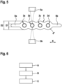
- opposite end sections 9a and 9b are formed on the plastic component 4" in continuation of the series of openings 3a to 3d.
- the two end sections 9a and 9b have a thickness D1 which is narrower than the component thickness D2 for welding along the linear direction X.
- the two end sections 9a and 9b serve as inlet and outlet sections for the laser welding device. If this moves along the plastic component 4", the laser beam is activated or deactivated in the area of the end sections 9a and 9b, so that mutual damage to the opposing laser beam units 5a and 5b is avoided.
- the multiple through-hole connection arrangement according to the invention is produced according to one of the three exemplary embodiments described above using the laser welding device described above, such that in an initial step, the plastic component 4 with the prefabricated multiple through-holes 3a to 3d is first provided.
- the electrical cables 1a to 1d are inserted through associated openings 3a to 3d.
- the component dimensions are selected so that the assembled components come into contact with each other.
- thermal welding C of the electrical cables to the plastic component takes place in the area of the respective opening to produce the material-tight component connection, whereby the laser beam units positioned opposite one another are activated and moved in a linear direction along the row of openings 3a to 3d, so that the material-tight connection is created after cooling by superficial melting of the materials to be joined together.
Landscapes
- Engineering & Computer Science (AREA)
- Physics & Mathematics (AREA)
- Mechanical Engineering (AREA)
- Optics & Photonics (AREA)
- Electromagnetism (AREA)
- Health & Medical Sciences (AREA)
- Toxicology (AREA)
- General Engineering & Computer Science (AREA)
- Thermal Sciences (AREA)
- Architecture (AREA)
- Civil Engineering (AREA)
- Structural Engineering (AREA)
- Lining Or Joining Of Plastics Or The Like (AREA)
- Laser Beam Processing (AREA)
Description
- Die vorliegende Erfindung betrifft ein Verfahren zur Herstellung einer Durchsteckverbindungsanordnung mehrerer elektrischer Kabel und/oder fluidführender Schläuche, mit einer aus einem Kunststoff bestehenden Ummantelung, welche beabstandet nebeneinander angeordnet durch je zugeordnete Durchbrüche eines Kunststoffbauteils verlaufen. Daneben betrifft die Erfindung auch eine Laserstrahlvorrichtung zur Herstellung einer thermischen Verschweißung, welche im Zusammenhang mit diesem Verfahren ausgeführt wird.
- Das Einsatzgebiet der Erfindung erstreckt sich vorzugsweise auf die Kraftfahrzeugtechnik und darüber hinaus auch auf andere Anwendungsgebiete, bei denen mehrere elektrische Kabel oder fluidführende Schläuche abgedichtet durch ein Bauteil, beispielsweise ein Gerätegehäuse, ein Tankbehälter oder eine Rohrleitung, hindurchzuführen oder hierin einzuführen sind. Derartige elektrische Kabel können beispielsweise stromführende Kabel einer elektrischen Energieversorgung, Sensorkabel oder dergleichen sein. Fluidführende Schläuche können beispielsweise Wasserleitungen, pneumatische Verbindungsleitungen oder dergleichen sein. Die elektrischen Kabel und fluidführenden Schläuche haben die Gemeinsamkeit, dass diese mit einer thermoplastischen Ummantelung aus Kunststoff versehen sind, um vornehmlich als elektrische Isolation oder Korrosionsschutz zu dienen. Im Falle fluidführender Schläuche kann die Funktion der Ummantelung auch gleichzeitig die Leitungsfunktion mit umfassen. Das Kunststoffbauteil, durch welches derartige elektrische Kabel oder fluidführende Schläuche im Rahmen der hier interessierenden Durchsteckverbindung abgedichtet durch- oder einzuführen ist, besteht aus einem thermoplastischen Kunststoff.
- Aus dem allgemein bekannten Stand der Technik gehen einfache Durchsteckverbindungen für elektrische Kabel oder fluidführende Schläuche in ein Kunststoffgehäuse oder dergleichen hervor, welche durch radiale Laserschweißvorgänge dichtgeschweißt werden. Durch die über ein oberflächliches Aufschmelzen an der Verbindungsstelle hervorgerufene stoffschlüssige Verbindung wird also eine Fixierung sowie eine Abdichtung erzielt. Hierbei dreht sich entweder das Kunststoffbauteil im Laserstrahl oder der Laserstrahl rotiert durch entsprechende Umlenkoptiken um die Verbindungsstelle. Für diese Art der Verbindung ist es vorteilhaft, wenn eine quasi simultane Verschweißung durchgeführt wird, also nicht gleichzeitig gesamte Verbindungsstelle bestrahlt wird, sondern dass diese mehrfach alternierend vom Laserstrahl überfahren wird, sodass sich die Verbindungsstelle nahezu simultan erwärmt und geschweißt wird. Problematisch erweist sich jedoch eine Situation, bei der eine zweite oder weitere Durchsteckverbindung direkt neben der so hergestellten einfachen Durchsteckverbindung zu realisieren ist, da das Laserlicht der Laserstrahleinheit nicht ungehindert radial an die Verbindungsstelle geleitet werden kann. Dieselbe Situation entsteht, wenn eine einfache Durchsteckverbindung direkt neben einem abschattenden Anbauteil verlaufen soll.
- Aus der
DE 10 2012 207 762 A1 geht eine geeignete technische Lösung zur Herstellung einer solchen Mehrfach-Durchsteckverbindung von vorzugsweise in einer Reihe angeordneten elektrischen Leitungen hervor, welche auf einer anderen Technologie basiert. Um mehrere elektrische Anschlusskabel in das Gehäuse eines Abgassensors abgedichtet einzuführen und hieran zu befestigen wird vorgeschlagen, einen Öffnungsquerschnitt für das Hineinführen der Anschlusskabel mit einem thermoplastischen Fluorpolymer-haltigen Material auszufüllen. Konkret wird beim einem bevorzugten Ausführungsbeispiel hierfür ein topfförmiges Führungsstück aus Stahl verwendet, dessen Bodenbereich Durchbrüche zum Hindurchstecken je eines Anschlusskabels aufweist. In den Innenraum des topfförmigen Führungsstücks taucht der Randbereich des Sensorgehäuses ein, welcher die Öffnung bildet. In den Zwischenraum wird das besagte thermoplastische Material eingelegt und verflüssigt. Nach dem Aushärten entsteht die abgedichtete Mehrfach-Durchsteckverbindung, welche gleichzeitig auch die Gehäuseöffnung abgedichtet verschließt. Die verschiedenartigen aufeinander folgenden Verfahrensschritte verursachen jedoch einen recht hohen Herstellungsaufwand. - Die
DE 103 38 732 A1 offenbart Schichten eines mehrschichtigen kartenförmigen Datenträgers, die im Laserdurchstrahlverfahren miteinander verbunden, insbesondere verschweißt werden. Gleichzeitig können Funktionselemente im Laserdurchstrahlverfahren im Kartenverbund fixiert und Strukturen mittels Laser in oder auf einzelnen Schichten des Schichtverbundes erzeugt werden. - Die
WO 2017/199938 A1 offenbart ein Verfahren zur Herstellung einer Kabeldurchführung durch Zusammenfügen mehrerer Teile, von denen wenigstens zwei thermoplastische Teile sind, die eine thermoplastische Zusammensetzung aufweisen, und wobei wenigstens zwei der thermoplastischen Teile (ein lichttransmissives Teil und ein lichtabsorbierendes Teil) durch Laserschweißen verbunden werden. - Die
DE 10 2016 212690 A1 offenbart ein Verfahren zum Ausbilden einer Laserschweißverbindung, bei dem zwei Fügepartner durch Einwirkung eines Laserstrahls in einem Fügebereich unter Ausbildung einer Schweißnaht miteinander verbunden werden, wobei der eine Fügepartner aus einem für Laserstrahlung transparenten Material und der andere Fügepartner aus einem für Laserstrahlung absorbierenden Material besteht, und wobei von den zwei Fügepartnern eine Aufnahme für ein von den Fügepartnern separates Bauteil ausgebildet wird. - Es ist daher die Aufgabe der vorliegenden Erfindung eine Durchsteckverbindungsanordnung für vorzugsweise mehrere elektrische Kabel oder fluidführende Schläuche der gattungsgemäßen Art dahingehend weiter zu verbessern, dass eine einfache und schnelle Fertigung möglich wird, welche sich durch eine zuverlässige Abdichtung zwischen den Verbindungspartnern auszeichnet.
- Die Aufgabe wird verfahrenstechnisch durch Anspruch 1 gelöst, hinsichtlich einer hierdurch entstehenden Durchsteckverbindungsanordnung wird auch Anspruch 6 verwiesen. Der Anspruch 11 gibt eine spezielle Laserschweißvorrichtung zur Herstellung der erfindungsgemäßen Durchsteckverbindungsanordnung an. Die Erfindung schließt die verfahrenstechnische Lehre ein, dass die Herstellung einer Mehrfach-Durchsteckverbindungsanordnung der vorstehend beschriebenen Art ein Kunststoffbauteil voraussetzt, welches mit mehreren vorgefertigten Durchbrüchen zunächst bereitzustellen ist. Die Durchbrüche können beispielsweise spritzgießtechnisch hergestellt werden oder durch Spanen, beispielsweise bohrtechnisch, angefertigt werden. Nachfolgend werden die elektrischen Kabel und/oder fluidführenden Schläuche in die je zugeordneten Durchbrüche montiert, also hindurchgesteckt, sodass die Außenwandung der aus Kunststoff bestehenden Ummantelung mit der Innenwandlung der jeweiligen Durchbrüche des Kunststoffbauteils in Kontakt kommen. Dazu sollten die elektrischen Kabel bzw. fluidführenden Schläuche gegenüber den ihnen zugeordneten Durchbrüchen eine Übergangspassung bilden. Schließlich werden die elektrischen Kabel bzw. fluidführenden Schläuche mit dem Kunststoffbauteil im Bereich des jeweiligen Durchbruchs zur Erzeugung einer stoffschlüssigen dichtenden Bauteilverbindung thermisch verschweißt, indem:
- mindestens zwei einander gegenüberliegend positionierte Laserstrahleinheiten auf eine je zugeordnete initiale Verbindungsstelle ausgerichtet werden, wonach
- die gegenüberliegenden Laserstrahleinheiten aktiviert und in eine lineare Relativbewegung quer zur Verlaufsrichtung der Durchbrüche, also in Querschnittsrichtung, versetzt werden, um durch oberflächliches Aufschmelzen der thermoplastischen Ummantelung mit dem thermoplastischen Kunststoffbauteil die stoffschlüssige Verbindung zu schaffen.
- Der Vorteil der erfindungsgemäßen Lösung liegt insbesondere darin, dass in zeitsparender Weise gleichzeitig von zwei einander gegenüberliegenden Laserstrahleinheiten aus geschweißt wird, zwischen denen sich das Bauteil befindet. Hierdurch lässt sich zudem jede Stelle des umlaufenden Durchbruchs erreichen, ohne dass das Werkzeug oder das Werkstück eine Drehbewegung ausführen müssen. Die erfindungsgemäße Lösung überwindet damit das Vorurteil, dass eine derartige Verschweißung per Laserstrahl nur mit einer Vorrichtung möglich sein soll, welche einen äquidistanten Abstand zwischen der Laserstrahleinheit und der Schweißstelle sicherstellt. Basierend auf dieser Erkenntnis lässt sich nun auch die eingangs diskutierte Abschattungsproblematik bei mehreren nebeneinanderliegenden elektrischen Kabeln oder fluidführenden Schläuchen lösen, sodass auch derartige Mehrfach-Durchsteckverbindungen einer Laserschweiß-Technologie zugänglich sind.
- Vorzugsweise besteht das Kunststoffbauteil aus einem transparenten oder transluzenten thermoplastischen Kunststoff und ist insoweit lichtdurchlässig, um den Laserstrahl zumindest teilweise hindurchzuleiten, also nur eine geringfügige Brechung und Streuung des Lichts zu bewirken. Hierdurch ist eine Verschweißung nicht allein auf den von außen her zugänglichen Randbereich der Durchbrüche beschränkt, sondern kann auch im innenliegenden Mantelbereich erfolgen.
- Um eine möglichst kurze Herstellungszeit zu realisieren wird vorgeschlagen, dass die gegenüberliegenden Laserstrahleinheiten vorzugsweise synchron in Linearrichtung X entlang des Kunststoffbauteils verfahren werden. Durch diese Gleichzeitigkeit kann die abgedichtete Mehrfach-Durchsteckverbindung in einem Zug geschaffen werden.
- Gemäß einer bevorzugten Ausführungsform zur Durchführung des erfindungsgemäßen Verfahrens wird vorgeschlagen, dass die einander gegenüberliegenden Laserstrahleinheiten parallel zum ortsfest eingespannten Kunststoffbauteil verfahren werden. Alternativ ist es jedoch auch denkbar, dass das Kunststoffbauteil zwischen einander gegenüberliegenden ortsfesten Laserstrahleinheiten verfahren wird. Je nach Abmessungen und Gewicht des Werkstücks in Relation zum Werkzeug kann eine der beiden Alternativen zum Einsatz kommen.
- Gemäß eines bevorzugten Ausführungsbeispiels einer Werkstoffpaarung für die erfindungsgemäße Lösung wird vorgeschlagen, dass die Ummantelung aus einem Kunststoffmaterial, ausgewählt aus einer Gruppe umfassend, Polyamid (PA), Polyethylen (PE), Polypropylen (PP), Polyvinylchlorid (PVC), Elastoplaste (TPE), Polyethylenterephthalat (PET), Fluorethylenpropylen (FEP), Polytetrafluorethylen (PTFE) und dergleichen besteht, wohingegen das Kunststoffbauteil aus demselben oder einem hiermit verschweißbaren Material hergestellt ist.
- Gemäß einer die Erfindung weiter verbessernden Maßnahme wird vorgeschlagen, dass der äußere Konturverlauf des Kunststoffbauteils im Bereich der Durchbrüche derart hieran angepasst ist, dass sich zumindest im Strahlenweg der Laserstrahleinheit etwa gleiche Wandstärken ergeben. So kann der äußere Konturverlauf des Kunststoffbauteils beispielsweise entsprechend gewellt ausgebildet sein. Dieser Maßnahme liegt die Erkenntnis zugrunde, dass die Wanddicke des transparenten bis transluzenten Materials des Kunststoffbauteils nicht zu stark schwanken sollte, um eine sichere Laserschweißung zu ermöglichen. Dieses Erfordernis lässt sich durch eine konstruktive Anpassung der Bauteilform erfüllen. Das Kunststoffbauteil ist insoweit herstellungsoptimal konstruiert.
- Durch das transparente bis transluzente Material des Kunststoffbauteils wird das Laserlicht derart stark gestreut, dass auch bei direkter Gegenüberlage der Laseroptiken beider Laserstrahleinheiten die eine Laseroptik und auch die hierin integrierte Pyrometermessung der Oberflächentemperatur nicht von der gegenüberliegenden Laseroptik beeinflusst wird. Die Pyrometermessung dient der Regelung des Laserschweißprozesses in allgemein bekannter Weise.
- Gemäß einer anderen die Erfindung weiter verbessernden Maßnahme wird vorgeschlagen, dass am Kunststoffbauteil in Fortsetzung eine Reihe von Durchbrüchen für hindurchzuführende elektrische Kabel oder fluidführende Schläuche einander gegenüberliegende Endabschnitte angeordnet sind, welche eine Dicke D1 aufweisen, die schmaler als die Bauteildicke D2 im Bereich der Durchbrüche ist. Auch diese gegenüberliegenden Endabschnitte dienen einem herstellungsoptimalen Bauteildesign, um zu verhindern, dass in einer Einlauf- und Auslaufphase der Laserverschweißung die Laseroptiken der einander gegenüberliegenden Laserstrahleinheiten sich gegeneinander schädigen. Weitere, die Erfindung verbessernde Maßnahmen werden nachstehend gemeinsam mit der Beschreibung bevorzugten Auszugsbeispiele der Erfindung anhand der Figuren näher dargestellt.
- Es zeigt:
- Figur 1
- eine schematische Seitenansicht einer Mehrfach-Durchsteckverbindungsanordnung für elektrische Kabel,
- Figur 2
- eine schematische Draufsicht eines ersten Ausführungsbeispiels für eine herstellungsoptimale Bauteilgestaltung,
- Figur 3
- eine schematische Seitenansicht einer Stirnseite der Mehrfach-Durchsteckverbindungsanordnung nach
Figur 1 und Figur 2 , - Figur 4
- eine schematische Draufsicht eines zweiten Ausführungsbeispiels für eine herstellungsoptimale Bauteilgestaltung,
- Figur 5
- eine schematische Draufsicht eines dritten Ausführungsbeispiels für eine herstellungsoptimale Bauteilgestaltung,
- Figur 6
- einen schematischen Ablaufplan eines Verfahrens zur Herstellung einer Mehrfach-Durchsteckverbindungsanordnung.
- Nach
Figur 1 besteht eine exemplarische Durchsteckverbindungsanordnung aus mehreren elektrischen Kabeln 1a bis 1d, welche jeweils mit einer aus thermoplastischem Kunststoff bestehenden Ummantelung 2 versehen sind. Die einzelnen elektrischen Kabel 1a bis 1d sind beabstandet nebeneinander angeordnet und durch je zugeordnete Durchbrüche 3a bis 3d eines transparenten thermoplastischen Kunststoffbauteils 4 geführt. - Zur Herstellung einer thermischen Verschweißung der elektrischen Kabel 1a bis 1d mit dem Kunststoffbauteil 4 dient eine Laserschweißvorrichtung, welche im Wesentlichen ein paar von gegenüberliegend positionierten Laserstrahleinheiten 5a und 5b umfasst. Die beiden gegenüberliegenden Laserstrahleinheiten 5a und 5b durchstrahlen jeweils das transparente Material des Kunststoffbauteils 4 und sind hier exemplarisch beidseits des elektrischen Kabels 1b fokussiert, um an dieser Verbindungsstelle das elektrische Kabel 1b mit dem Kunststoffbauteil 4 thermisch zu verschweißen, sodass eine stoffschlüssig dichtende Bauteilverbindung entsteht. Um alle elektrischen Kabel 1a bis 1d auf diese Weise mit dem Kunststoffbauteil 4 zu verbinden, werden die Laserstrahleinheiten 5a und 5b synchron in Linearrichtung X entlang des Kunststoffbauteils 4 verfahren. Dabei bewegen sich die einander gegenüberliegenden Laserstrahleinheiten 5a und 5b parallel zum ortsfest eingespannten Kunststoffbauteil 4.
- Die Laserschweißvorrichtung umfasst ferner je ein den beiden Laserstrahleinheiten 5a und 5b zugeordnete Pyrometermesseinrichtung 6a bzw. 6b, welche das allgemein bekannte Messprinzip die Oberflächentemperatur an der aktuellen Verbindungsstelle 7a bzw. 7b misst, um die zugeordneten Laserstrahleinheiten 5a bzw. 5b geregelt anzusteuern. Die Regelung erfolgt auf eine materialabhängig eingestellte Soll-Temperatur an den Verbindungsstellen 7a sowie 7b, um dort ein lokales Aufschmelzen des Kunststoffmaterials zur Herstellung der gewünschten stoffschlüssigen Verbindung zu erzeugen.
- Die
Figur 3 verdeutlicht in der Seitenansicht, dass das Paar von gegenüberliegend positionierten Laserstrahleinheiten 5a und 5b als Werkzeug auf eine je zugeordnete auf derselben Höhe liegende initiale Verbindungsstelle 7a bzw. 7b des Kunststoffbauteils 4 als Werkstück ausgerichtet sind. - Gemäß dem in der
Figur 4 dargestellten Ausführungsbeispiel ist der äußere Konturverlauf 8 des Kunststoffbauteils 4' im Bereich der Durchbrüche 3a bis 3b gewellt ausgebildet, so dass sich zumindest im Strahlenweg der Laserstrahleinheiten 5a und 5b in etwa gleiche Wandstärken ergeben. Hierdurch wird ein hinreichend gleichmäßiges Aufschmelzen des Kunststoffmaterials zur Herstellung der stoffschlüssigen Verbindung gewährleistet. - Nach dem in
Figur 5 dargestellten weiteren Ausführungsbeispiel ist am Kunststoffbauteil 4" in Fortsetzung der Reihe von Durchbrüchen 3a bis 3d einander gegenüberliegende Endabschnitte 9a bzw. 9b angeformt. Die beiden Endabschnitte 9a und 9b weisen eine Dicke D1, welche schmaler als die Bauteildicke D2 für ein Verschweißen entlang der Linearrichtung X dienen die beiden Endabschnitte 9a und 9b als Ein- bzw. Auslaufabschnitte für die Laserschweißvorrichtung. Verfährt diese entlang des Kunststoffbauteils 4", so erfolgt im Bereich der Endabschnitte 9a und 9b das Aktivieren bzw. Deaktivieren des Laserstrahls, so dass eine gegenseitige Schädigung der einander gegenüberliegenden Laserstrahleinheiten 5a und 5b vermieden wird. - Nach
Figur 6 wird mit der vorstehend beschriebenen Laserschweißvorrichtung die erfindungsgegenständliche Mehrfach-Durchstreckverbindungsanordnung nach einem der drei vorstehend beschriebenen exemplarischen Ausführungsbeispiele derart hergestellt, dass in einem initialen Schritt zunächst ein Bereitstellen A des Kunststoffbauteils 4 mit den vorgefertigten mehreren Durchbrüchen 3a bis 3d erfolgt. - In einem sich hieran anschließenden Herstellungsschritt eines Montierens B werden die elektrischen Kabel 1a bis 1d durch hinzugeordneten Durchbrüche 3a bis 3d gesteckt. Dabei sind die Bauteilmaße so gewählt, dass die miteinander montierten Bauteile miteinander in Kontakt kommen.
- In einem nächsten Herstellungsschritt erfolgt ein thermisches Verschweißen C der elektrischen Kabel mit dem Kunststoffbauteil im Bereich des jeweiligen Durchbruchs zur Erzeugung der stoffschlüssig dichtenden Bauteilverbindung, wobei die einander gegenüberliegend positionierten Laserstrahleinheiten aktiviert und in linearer Verlaufsrichtung entlang der Reihe von Durchbrüchen 3a bis 3d verfahren werden, sodass durch oberflächliches Aufschmelzen der miteinander zu verbindenden Materialien die stoffschlüssige Verbindung nach dem Abkühlen entsteht.
- Die Erfindung ist nicht beschränkt auf die vorstehend beschriebenen bevorzugten Ausführungsbeispiele. Es sind vielmehr auch Abordnungen hiervon denkbar, welche im Schutzbereich der nachfolgenden Ansprüche mit umfasst sind.
- Nicht von den geltenden Ansprüchen umfasst ist es beispielsweise auch möglich, statt einer Mehrzahl von elektrischen Kabeln oder fluidführenden Schläuchen auch nur ein einziges Bauteil dieser Art mit einem Kunststoffbauteil zu einer Durchsteckverbindungsanordnung der erfindungsgemäßen Art zu vereinen. Dies kann insbesondere dann angewendet werden, wenn direkt neben dem zu montierenden elektrischen Kabel oder dem fluidführenden Schlauch ein abschattendes Bauteil angeordnet ist, welches eine rotative Werkzeugbewegung nicht zulässt. Ferner ist es auch denkbar, durch eine mehrfache Überfahrt der Verbindungsstellen eine quasi simultane Verschweißung zu realisieren.
Claims (11)
- Verfahren zur Herstellung einer Durchsteckverbindungsanordnung mehrerer elektrischer Kabel (1a - 1d) und/oder fluidführender Schläuche, mit einer aus einem Kunststoff bestehenden Ummantelung (2), welche beabstandet nebeneinander angeordnet durch je zugeordnete Durchbrüche (3a - 3d) eines Kunststoffbauteils (4) verlaufen, umfassend die folgenden Schritte:- Bereitstellen (A) des Kunststoffteils (4) mit den vorgefertigten mehreren Durchbrüchen (3a - 3d),- Montieren (B) der elektrischen Kabel (1a - 1d) und/oder fluidführenden Schläuche durch die je zugeordneten Durchbrüche (3a - 3d), so dass die Außenwandung der aus Kunststoff bestehenden Ummantelung (2) mit der Innenwandung der jeweiligen Durchbrüche (3a - 3d) des Kunststoffbauteils (4) in Kontakt kommen,- Thermisches Verschweißen (C) der elektrischen Kabel (1a - 1d) und/oder fluidführender Schläuche mit dem Kunststoffbauteil (4) im Bereich des jeweiligen Durchbruchs (3a - 3d), zur Erzeugung einer stoffschlüssig dichtenden Bauteilverbindung, indem:- mindestens zwei einander gegenüberliegend positionierte Laserstrahleinheiten (5a, 5b) auf eine je zugeordnete initiale Verbindungsstelle ausgerichtet werden, wonach- die gegenüberliegenden Laserstrahleinheiten (5a, 5b) aktiviert und in eine lineare Relativbewegung quer zur Verlaufsrichtung der Durchbrüche (3a - 3d) gesetzt werden, um durch oberflächliches Aufschmelzen der Ummantelung (2) mit dem Kunststoffbauteil (4) die stoffschlüssige Verbindung zu schaffen.
- Verfahren nach Anspruch 1,
dadurch gekennzeichnet, dass das Kunststoffbauteil (4) zumindest im Bereich der Durchdringungsstellen lichtdurchlässig ist und insbesondere aus einem transparenten oder transluzenten thermoplastischen Kunststoff besteht, um den von den Laserstrahleinheiten (5a, 5b) emittierten Laserstrahl zumindest teilweise hindurchzuleiten. - Verfahren nach Anspruch 1,
dadurch gekennzeichnet, dass die gegenüberliegenden Laserstrahleinheiten (5a, 5b) synchron in Linearrichtung (X) entlang des Kunststoffbauteils (4) verfahren. - Verfahren nach Anspruch 1,
dadurch gekennzeichnet, dass die einander gegenüberliegenden Laserstrahleinheiten (5a, 5b) parallel zum ortsfesten Kunststoffbauteil (4) verfahren werden. - Verfahren nach Anspruch 1,
dadurch gekennzeichnet, dass das Kunststoffbauteil (4) zwischen den einander gegenüberliegenden ortsfesten Laserstrahleinheiten (5a, 5b) verfahren wird. - Durchsteckverbindungsanordnung mehrerer elektrischer Kabel (1a - 1d) und/oder fluidführender Schläuche, mit einer aus einem Kunststoff bestehenden Ummantelung (2), welche beabstandet nebeneinander angeordnet durch je zugeordnete Durchbrüche (3a - 3d) eines Kunststoffbauteils (4) verlaufen, hergestellt nach einem Verfahren gemäß der vorstehenden Ansprüche 1 bis 5.
- Durchsteckverbindungsanordnung nach Anspruch 6,
dadurch gekennzeichnet, dass die Ummantelung (2) aus einem Kunststoffmaterial, ausgewählt aus einer Gruppe, umfassend, Polyamid (PA), Polyethylen (PE), Polypropylen (PP), Polyvinylchlorid (PVC), Elastoplaste (TPE), Polyethylenterephthalat (PET), Fluorethylenpropylen (FEP), Polytetrafluorethylen (PTFE) besteht, wohingegen das Kunststoffbauteil (4) aus demselben oder einem hiermit verschweißbaren Material hergestellt ist. - Durchsteckverbindungsanordnung nach Anspruch 6,
dadurch gekennzeichnet, dass der äußere Konturverlauf (8) des Kunststoffbauteils (4') im Bereich der Durchbrüche (3a - 3d) derart hieran angepasst ist, dass sich zumindest im Strahlenweg der Laserstrahleinheiten (5a, 5b) in etwa gleiche Wandstärken ergeben. - Durchsteckverbindungsanordnung nach Anspruch 8,
dadurch gekennzeichnet, dass der äußere Konturverlauf (8) des Kunststoffbauteils (4') gewellt ausgebildet ist. - Durchsteckverbindungsanordnung nach Anspruch 8 oder 9,
dadurch gekennzeichnet, dass am Kunststoffbauteil (4") in Fortsetzung der Reihe von Durchbrüchen (3a - 3d) einander gegenüberliegende Endabschnitte (9a, 9b) angeordnet sind, die eine Dicke (D1) aufweisen, welche schmaler als die Bauteildicke (D2) im Bereich der Durchbrüche (3a - 3d) ist. - Laserschweißvorrichtung zur Herstellung einer thermischen Verschweißung von elektrischen Kabeln (1a -1d) und/oder fluidführenden Schläuchen mit einem Kunststoffbauteil (4) für eine Durchsteckverbindungsanordnung nach einem der Ansprüche 6 bis 10,
dadurch gekennzeichnet, dass mindestens ein Paar von gegenüberliegend positionierten Laserstrahleinheiten (5a, 5b) als Werkzeug auf eine je zugeordnete initiale Verbindungsstelle (7a, 7b) eines Kunststoffbauteils (4) als Werkstück ausgerichtet sind, wobei Mittel zur Ausführung einer linearen Relativbewegung zwischen Werkstück und Werkzeug zur Erzeugung einer thermischen Schweißnaht vorgesehen sind, und dass die Laserstrahleinheiten (5a, 5b) mit jeweils einer integrierten Pyrometermesseinrichtung (6a; 6b) zur Messung der Oberflächentemperatur an der Verbindungsstelle (7a; 7b) ausgestattet sind.
Applications Claiming Priority (2)
| Application Number | Priority Date | Filing Date | Title |
|---|---|---|---|
| DE102018211883.3A DE102018211883A1 (de) | 2018-07-17 | 2018-07-17 | Verfahren und Vorrichtung zur Herstellung einer Durchsteckverbindung mehrerer Kabel oder Schläuchen durch ein Kunststoffbauteil |
| PCT/EP2019/064645 WO2020015916A1 (de) | 2018-07-17 | 2019-06-05 | Verfahren und vorrichtung zur herstellung einer durchsteckverbindung mehrerer kabel oder schläuchen durch ein kunststoffbauteil |
Publications (2)
| Publication Number | Publication Date |
|---|---|
| EP3823815A1 EP3823815A1 (de) | 2021-05-26 |
| EP3823815B1 true EP3823815B1 (de) | 2024-08-07 |
Family
ID=66793993
Family Applications (1)
| Application Number | Title | Priority Date | Filing Date |
|---|---|---|---|
| EP19729253.5A Active EP3823815B1 (de) | 2018-07-17 | 2019-06-05 | Verfahren und vorrichtung zur herstellung einer durchsteckverbindung mehrerer kabel oder schläuchen durch ein kunststoffbauteil |
Country Status (4)
| Country | Link |
|---|---|
| US (1) | US11426948B2 (de) |
| EP (1) | EP3823815B1 (de) |
| DE (1) | DE102018211883A1 (de) |
| WO (1) | WO2020015916A1 (de) |
Families Citing this family (2)
| Publication number | Priority date | Publication date | Assignee | Title |
|---|---|---|---|---|
| CN120615123A (zh) * | 2022-12-02 | 2025-09-09 | 艾姆皮瑞克公司 | Mtres1相关疾病和病症的治疗 |
| WO2025098804A1 (de) * | 2023-11-08 | 2025-05-15 | Hirschmann Automotive Gmbh | MITTELS LASERSCHWEIßEN AUF KABELMANTEL FESTGELEGTE TÜLLE |
Family Cites Families (6)
| Publication number | Priority date | Publication date | Assignee | Title |
|---|---|---|---|---|
| US6451152B1 (en) * | 2000-05-24 | 2002-09-17 | The Boeing Company | Method for heating and controlling temperature of composite material during automated placement |
| DE10338732A1 (de) * | 2003-08-22 | 2005-03-24 | Giesecke & Devrient Gmbh | Kartenförmiger Mehrschichtverbund |
| US20110014731A1 (en) * | 2009-07-15 | 2011-01-20 | Kelvin Nguyen | Method for sealing a photonic device |
| DE102012207762A1 (de) | 2012-05-09 | 2013-11-14 | Robert Bosch Gmbh | Abgassensor |
| JP6783548B2 (ja) * | 2016-05-18 | 2020-11-11 | 西遠ゴム工業株式会社 | グロメットおよびその製造方法、グロメット付きワイヤハーネスおよびその製造方法、ならびにグロメット組み立て用パーツセット |
| DE102016212690A1 (de) * | 2016-07-12 | 2018-01-18 | Robert Bosch Gmbh | Verfahren zum Ausbilden einer Laserschweißverbindung und Bauteileverbund |
-
2018
- 2018-07-17 DE DE102018211883.3A patent/DE102018211883A1/de not_active Withdrawn
-
2019
- 2019-06-05 WO PCT/EP2019/064645 patent/WO2020015916A1/de not_active Ceased
- 2019-06-05 EP EP19729253.5A patent/EP3823815B1/de active Active
- 2019-06-05 US US17/261,079 patent/US11426948B2/en active Active
Also Published As
| Publication number | Publication date |
|---|---|
| EP3823815A1 (de) | 2021-05-26 |
| US20210308952A1 (en) | 2021-10-07 |
| DE102018211883A1 (de) | 2020-01-23 |
| US11426948B2 (en) | 2022-08-30 |
| WO2020015916A1 (de) | 2020-01-23 |
Similar Documents
| Publication | Publication Date | Title |
|---|---|---|
| EP3047240B1 (de) | Verfahren zum herstellen einer magneteinheit für eine sensoreinrichtung zum erfassen einer einen rotationszustand einer lenkwelle eines kraftfahrzeugs charakterisierenden messgrösse, magneteinheit, sensoreinrichtung und kraftfahrzeug | |
| EP3823815B1 (de) | Verfahren und vorrichtung zur herstellung einer durchsteckverbindung mehrerer kabel oder schläuchen durch ein kunststoffbauteil | |
| DE102013217388A1 (de) | Faser-Verbund-Kunststoffbauteil | |
| DE102015220473A1 (de) | Verfahren zum Herstellen eines Gehäusebauteils mit Schirmung vor elektromagnetischer Strahlung und mit Umweltdichtungsfunktion sowie Gehäusebauteil | |
| DE10326906A1 (de) | Akkumulator und Verfahren zur Herstellung einer dichten Kontaktklemmendurchführung | |
| EP2000659B1 (de) | Ansaugsystem | |
| EP1044789B1 (de) | Verfahren zur Herstellung eines Kunststoffbauteils und Kraftstoffbehälter für ein Kraftfahrzeug | |
| EP1518633A1 (de) | Schweissverfahren, zusammengesetzter Körper und Verwendung einer Laseranlage zur Herstellung des zusammengesetzten Körpers | |
| DE19640816A1 (de) | Dichtelement | |
| WO2016097091A1 (de) | Bürste und verfahren zu deren herstellung | |
| EP2895779B1 (de) | Vorrichtung zum verbinden von zwei fluid führenden leitungen | |
| DE102013211511B4 (de) | Leiterbahnstanzgitter und Verfahren zum Fertigen desselben | |
| DE10342921B4 (de) | Verfahren zum Verschweißen von Kunststoffen und einem hierzu notwendigen Schweißmittel | |
| EP3554799A1 (de) | Kunststoffformteil für eine formteilanordnung, entsprechende formteilanordnung sowie verfahren zum herstellen einer formteilanordnung | |
| EP2982227B1 (de) | Verfahren und vorrichtung zur herstellung einer abdichtung zwischen einem träger eines elektrischen bauteils und einer den träger zumindest teilweise umgebenden umspritzung | |
| DE602004011147T2 (de) | Laserverschweisster Luftansaugkrümmer | |
| DE10133731A1 (de) | Verfahren zum Herstellen eines elktrischen Endprodukts, welches Löt-oder Schweißstellen aufweist | |
| EP3293432B1 (de) | Bauteil mit rohrabschnitt mit emailliertem bund | |
| EP1243830B1 (de) | Vakuumdurchführung für Ultrahochvakuum-Anlagen | |
| DE19820198B4 (de) | Vorrichtung zum Verschweißen großflächiger Spritzgußbauteile aus Kunststoff | |
| DE102004025931B3 (de) | Baugruppe aus miteinander verbundenen leitfähigen Bauteilen, welche KTL-Korrosionsschutz tragen und Verfahren zu deren Herstellung | |
| DE1939318C3 (de) | Schweißbare Anordnung zum Verschließen von Prüföffnungen, fehlerhaften Stellen o.dgl. bei Kabelgarnituren aus Polyäthylen oder polyäthylenummantelten Kabeln | |
| WO2024061454A1 (de) | Kabelabdichtungsgehäuse sowie verfahren zur herstellung eines solchen gehäuses | |
| DE102016213404A1 (de) | Verfahren zum Herstellen einer fluidischen Vorrichtung für ein Lab-on-Chip-System und fluidische Vorrichtung für ein Lab-on-Chip-System | |
| DE102022123119A1 (de) | Hybridbauteil und Verfahren zur Herstellung desselben |
Legal Events
| Date | Code | Title | Description |
|---|---|---|---|
| STAA | Information on the status of an ep patent application or granted ep patent |
Free format text: STATUS: UNKNOWN |
|
| STAA | Information on the status of an ep patent application or granted ep patent |
Free format text: STATUS: THE INTERNATIONAL PUBLICATION HAS BEEN MADE |
|
| PUAI | Public reference made under article 153(3) epc to a published international application that has entered the european phase |
Free format text: ORIGINAL CODE: 0009012 |
|
| STAA | Information on the status of an ep patent application or granted ep patent |
Free format text: STATUS: REQUEST FOR EXAMINATION WAS MADE |
|
| 17P | Request for examination filed |
Effective date: 20210217 |
|
| AK | Designated contracting states |
Kind code of ref document: A1 Designated state(s): AL AT BE BG CH CY CZ DE DK EE ES FI FR GB GR HR HU IE IS IT LI LT LU LV MC MK MT NL NO PL PT RO RS SE SI SK SM TR |
|
| DAV | Request for validation of the european patent (deleted) | ||
| DAX | Request for extension of the european patent (deleted) | ||
| STAA | Information on the status of an ep patent application or granted ep patent |
Free format text: STATUS: EXAMINATION IS IN PROGRESS |
|
| 17Q | First examination report despatched |
Effective date: 20230816 |
|
| RIC1 | Information provided on ipc code assigned before grant |
Ipc: B29L 31/34 20060101ALN20231218BHEP Ipc: F16L 5/02 20060101ALI20231218BHEP Ipc: H02G 15/013 20060101ALI20231218BHEP Ipc: H02G 3/22 20060101ALI20231218BHEP Ipc: B60R 16/02 20060101ALI20231218BHEP Ipc: B29C 65/16 20060101AFI20231218BHEP |
|
| GRAP | Despatch of communication of intention to grant a patent |
Free format text: ORIGINAL CODE: EPIDOSNIGR1 |
|
| STAA | Information on the status of an ep patent application or granted ep patent |
Free format text: STATUS: GRANT OF PATENT IS INTENDED |
|
| INTG | Intention to grant announced |
Effective date: 20240129 |
|
| GRAS | Grant fee paid |
Free format text: ORIGINAL CODE: EPIDOSNIGR3 |
|
| GRAA | (expected) grant |
Free format text: ORIGINAL CODE: 0009210 |
|
| STAA | Information on the status of an ep patent application or granted ep patent |
Free format text: STATUS: THE PATENT HAS BEEN GRANTED |
|
| AK | Designated contracting states |
Kind code of ref document: B1 Designated state(s): AL AT BE BG CH CY CZ DE DK EE ES FI FR GB GR HR HU IE IS IT LI LT LU LV MC MK MT NL NO PL PT RO RS SE SI SK SM TR |
|
| REG | Reference to a national code |
Ref country code: GB Ref legal event code: FG4D Free format text: NOT ENGLISH |
|
| REG | Reference to a national code |
Ref country code: CH Ref legal event code: EP |
|
| REG | Reference to a national code |
Ref country code: IE Ref legal event code: FG4D Free format text: LANGUAGE OF EP DOCUMENT: GERMAN |
|
| REG | Reference to a national code |
Ref country code: DE Ref legal event code: R096 Ref document number: 502019011835 Country of ref document: DE |
|
| REG | Reference to a national code |
Ref country code: LT Ref legal event code: MG9D |
|
| REG | Reference to a national code |
Ref country code: NL Ref legal event code: MP Effective date: 20240807 |
|
| PG25 | Lapsed in a contracting state [announced via postgrant information from national office to epo] |
Ref country code: NO Free format text: LAPSE BECAUSE OF FAILURE TO SUBMIT A TRANSLATION OF THE DESCRIPTION OR TO PAY THE FEE WITHIN THE PRESCRIBED TIME-LIMIT Effective date: 20241107 |
|
| PG25 | Lapsed in a contracting state [announced via postgrant information from national office to epo] |
Ref country code: FI Free format text: LAPSE BECAUSE OF FAILURE TO SUBMIT A TRANSLATION OF THE DESCRIPTION OR TO PAY THE FEE WITHIN THE PRESCRIBED TIME-LIMIT Effective date: 20240807 Ref country code: NL Free format text: LAPSE BECAUSE OF FAILURE TO SUBMIT A TRANSLATION OF THE DESCRIPTION OR TO PAY THE FEE WITHIN THE PRESCRIBED TIME-LIMIT Effective date: 20240807 Ref country code: PL Free format text: LAPSE BECAUSE OF FAILURE TO SUBMIT A TRANSLATION OF THE DESCRIPTION OR TO PAY THE FEE WITHIN THE PRESCRIBED TIME-LIMIT Effective date: 20240807 Ref country code: GR Free format text: LAPSE BECAUSE OF FAILURE TO SUBMIT A TRANSLATION OF THE DESCRIPTION OR TO PAY THE FEE WITHIN THE PRESCRIBED TIME-LIMIT Effective date: 20241108 Ref country code: PT Free format text: LAPSE BECAUSE OF FAILURE TO SUBMIT A TRANSLATION OF THE DESCRIPTION OR TO PAY THE FEE WITHIN THE PRESCRIBED TIME-LIMIT Effective date: 20241209 |
|
| PG25 | Lapsed in a contracting state [announced via postgrant information from national office to epo] |
Ref country code: BG Free format text: LAPSE BECAUSE OF FAILURE TO SUBMIT A TRANSLATION OF THE DESCRIPTION OR TO PAY THE FEE WITHIN THE PRESCRIBED TIME-LIMIT Effective date: 20240807 |
|
| PG25 | Lapsed in a contracting state [announced via postgrant information from national office to epo] |
Ref country code: LV Free format text: LAPSE BECAUSE OF FAILURE TO SUBMIT A TRANSLATION OF THE DESCRIPTION OR TO PAY THE FEE WITHIN THE PRESCRIBED TIME-LIMIT Effective date: 20240807 |
|
| PG25 | Lapsed in a contracting state [announced via postgrant information from national office to epo] |
Ref country code: IS Free format text: LAPSE BECAUSE OF FAILURE TO SUBMIT A TRANSLATION OF THE DESCRIPTION OR TO PAY THE FEE WITHIN THE PRESCRIBED TIME-LIMIT Effective date: 20241207 |
|
| PG25 | Lapsed in a contracting state [announced via postgrant information from national office to epo] |
Ref country code: HR Free format text: LAPSE BECAUSE OF FAILURE TO SUBMIT A TRANSLATION OF THE DESCRIPTION OR TO PAY THE FEE WITHIN THE PRESCRIBED TIME-LIMIT Effective date: 20240807 |
|
| PG25 | Lapsed in a contracting state [announced via postgrant information from national office to epo] |
Ref country code: RS Free format text: LAPSE BECAUSE OF FAILURE TO SUBMIT A TRANSLATION OF THE DESCRIPTION OR TO PAY THE FEE WITHIN THE PRESCRIBED TIME-LIMIT Effective date: 20241107 Ref country code: ES Free format text: LAPSE BECAUSE OF FAILURE TO SUBMIT A TRANSLATION OF THE DESCRIPTION OR TO PAY THE FEE WITHIN THE PRESCRIBED TIME-LIMIT Effective date: 20240807 |
|
| PG25 | Lapsed in a contracting state [announced via postgrant information from national office to epo] |
Ref country code: RS Free format text: LAPSE BECAUSE OF FAILURE TO SUBMIT A TRANSLATION OF THE DESCRIPTION OR TO PAY THE FEE WITHIN THE PRESCRIBED TIME-LIMIT Effective date: 20241107 Ref country code: PT Free format text: LAPSE BECAUSE OF FAILURE TO SUBMIT A TRANSLATION OF THE DESCRIPTION OR TO PAY THE FEE WITHIN THE PRESCRIBED TIME-LIMIT Effective date: 20241209 Ref country code: PL Free format text: LAPSE BECAUSE OF FAILURE TO SUBMIT A TRANSLATION OF THE DESCRIPTION OR TO PAY THE FEE WITHIN THE PRESCRIBED TIME-LIMIT Effective date: 20240807 Ref country code: NO Free format text: LAPSE BECAUSE OF FAILURE TO SUBMIT A TRANSLATION OF THE DESCRIPTION OR TO PAY THE FEE WITHIN THE PRESCRIBED TIME-LIMIT Effective date: 20241107 Ref country code: NL Free format text: LAPSE BECAUSE OF FAILURE TO SUBMIT A TRANSLATION OF THE DESCRIPTION OR TO PAY THE FEE WITHIN THE PRESCRIBED TIME-LIMIT Effective date: 20240807 Ref country code: LV Free format text: LAPSE BECAUSE OF FAILURE TO SUBMIT A TRANSLATION OF THE DESCRIPTION OR TO PAY THE FEE WITHIN THE PRESCRIBED TIME-LIMIT Effective date: 20240807 Ref country code: IS Free format text: LAPSE BECAUSE OF FAILURE TO SUBMIT A TRANSLATION OF THE DESCRIPTION OR TO PAY THE FEE WITHIN THE PRESCRIBED TIME-LIMIT Effective date: 20241207 Ref country code: HR Free format text: LAPSE BECAUSE OF FAILURE TO SUBMIT A TRANSLATION OF THE DESCRIPTION OR TO PAY THE FEE WITHIN THE PRESCRIBED TIME-LIMIT Effective date: 20240807 Ref country code: GR Free format text: LAPSE BECAUSE OF FAILURE TO SUBMIT A TRANSLATION OF THE DESCRIPTION OR TO PAY THE FEE WITHIN THE PRESCRIBED TIME-LIMIT Effective date: 20241108 Ref country code: FI Free format text: LAPSE BECAUSE OF FAILURE TO SUBMIT A TRANSLATION OF THE DESCRIPTION OR TO PAY THE FEE WITHIN THE PRESCRIBED TIME-LIMIT Effective date: 20240807 Ref country code: ES Free format text: LAPSE BECAUSE OF FAILURE TO SUBMIT A TRANSLATION OF THE DESCRIPTION OR TO PAY THE FEE WITHIN THE PRESCRIBED TIME-LIMIT Effective date: 20240807 Ref country code: BG Free format text: LAPSE BECAUSE OF FAILURE TO SUBMIT A TRANSLATION OF THE DESCRIPTION OR TO PAY THE FEE WITHIN THE PRESCRIBED TIME-LIMIT Effective date: 20240807 |
|
| PG25 | Lapsed in a contracting state [announced via postgrant information from national office to epo] |
Ref country code: SM Free format text: LAPSE BECAUSE OF FAILURE TO SUBMIT A TRANSLATION OF THE DESCRIPTION OR TO PAY THE FEE WITHIN THE PRESCRIBED TIME-LIMIT Effective date: 20240807 Ref country code: RO Free format text: LAPSE BECAUSE OF FAILURE TO SUBMIT A TRANSLATION OF THE DESCRIPTION OR TO PAY THE FEE WITHIN THE PRESCRIBED TIME-LIMIT Effective date: 20240807 Ref country code: DK Free format text: LAPSE BECAUSE OF FAILURE TO SUBMIT A TRANSLATION OF THE DESCRIPTION OR TO PAY THE FEE WITHIN THE PRESCRIBED TIME-LIMIT Effective date: 20240807 |
|
| PG25 | Lapsed in a contracting state [announced via postgrant information from national office to epo] |
Ref country code: EE Free format text: LAPSE BECAUSE OF FAILURE TO SUBMIT A TRANSLATION OF THE DESCRIPTION OR TO PAY THE FEE WITHIN THE PRESCRIBED TIME-LIMIT Effective date: 20240807 |
|
| PG25 | Lapsed in a contracting state [announced via postgrant information from national office to epo] |
Ref country code: CZ Free format text: LAPSE BECAUSE OF FAILURE TO SUBMIT A TRANSLATION OF THE DESCRIPTION OR TO PAY THE FEE WITHIN THE PRESCRIBED TIME-LIMIT Effective date: 20240807 |
|
| PG25 | Lapsed in a contracting state [announced via postgrant information from national office to epo] |
Ref country code: SK Free format text: LAPSE BECAUSE OF FAILURE TO SUBMIT A TRANSLATION OF THE DESCRIPTION OR TO PAY THE FEE WITHIN THE PRESCRIBED TIME-LIMIT Effective date: 20240807 |
|
| REG | Reference to a national code |
Ref country code: DE Ref legal event code: R097 Ref document number: 502019011835 Country of ref document: DE |
|
| PLBE | No opposition filed within time limit |
Free format text: ORIGINAL CODE: 0009261 |
|
| STAA | Information on the status of an ep patent application or granted ep patent |
Free format text: STATUS: NO OPPOSITION FILED WITHIN TIME LIMIT |
|
| 26N | No opposition filed |
Effective date: 20250508 |
|
| PGFP | Annual fee paid to national office [announced via postgrant information from national office to epo] |
Ref country code: FR Payment date: 20250627 Year of fee payment: 7 |
|
| PG25 | Lapsed in a contracting state [announced via postgrant information from national office to epo] |
Ref country code: SE Free format text: LAPSE BECAUSE OF FAILURE TO SUBMIT A TRANSLATION OF THE DESCRIPTION OR TO PAY THE FEE WITHIN THE PRESCRIBED TIME-LIMIT Effective date: 20240807 |
|
| PGFP | Annual fee paid to national office [announced via postgrant information from national office to epo] |
Ref country code: DE Payment date: 20250814 Year of fee payment: 7 |
|
| REG | Reference to a national code |
Ref country code: CH Ref legal event code: H13 Free format text: ST27 STATUS EVENT CODE: U-0-0-H10-H13 (AS PROVIDED BY THE NATIONAL OFFICE) Effective date: 20260127 |
|
| PG25 | Lapsed in a contracting state [announced via postgrant information from national office to epo] |
Ref country code: IT Free format text: LAPSE BECAUSE OF FAILURE TO SUBMIT A TRANSLATION OF THE DESCRIPTION OR TO PAY THE FEE WITHIN THE PRESCRIBED TIME-LIMIT Effective date: 20240807 |
|
| PG25 | Lapsed in a contracting state [announced via postgrant information from national office to epo] |
Ref country code: MC Free format text: LAPSE BECAUSE OF FAILURE TO SUBMIT A TRANSLATION OF THE DESCRIPTION OR TO PAY THE FEE WITHIN THE PRESCRIBED TIME-LIMIT Effective date: 20240807 |
|
| PG25 | Lapsed in a contracting state [announced via postgrant information from national office to epo] |
Ref country code: LU Free format text: LAPSE BECAUSE OF NON-PAYMENT OF DUE FEES Effective date: 20250605 |
|
| GBPC | Gb: european patent ceased through non-payment of renewal fee |
Effective date: 20250605 |
|
| REG | Reference to a national code |
Ref country code: BE Ref legal event code: MM Effective date: 20250630 |
|
| PG25 | Lapsed in a contracting state [announced via postgrant information from national office to epo] |
Ref country code: GB Free format text: LAPSE BECAUSE OF NON-PAYMENT OF DUE FEES Effective date: 20250605 |
|
| PG25 | Lapsed in a contracting state [announced via postgrant information from national office to epo] |
Ref country code: IE Free format text: LAPSE BECAUSE OF NON-PAYMENT OF DUE FEES Effective date: 20250605 |
|
| PG25 | Lapsed in a contracting state [announced via postgrant information from national office to epo] |
Ref country code: BE Free format text: LAPSE BECAUSE OF NON-PAYMENT OF DUE FEES Effective date: 20250630 |
|
| PG25 | Lapsed in a contracting state [announced via postgrant information from national office to epo] |
Ref country code: CH Free format text: LAPSE BECAUSE OF NON-PAYMENT OF DUE FEES Effective date: 20250630 |