EP3823402B1 - Funkrahmenübertragungsverfahren, vorrichtung und computerlesbares speichermedium - Google Patents
Funkrahmenübertragungsverfahren, vorrichtung und computerlesbares speichermedium Download PDFInfo
- Publication number
- EP3823402B1 EP3823402B1 EP20191368.8A EP20191368A EP3823402B1 EP 3823402 B1 EP3823402 B1 EP 3823402B1 EP 20191368 A EP20191368 A EP 20191368A EP 3823402 B1 EP3823402 B1 EP 3823402B1
- Authority
- EP
- European Patent Office
- Prior art keywords
- subframe
- transmission
- time unit
- radio frame
- wireless network
- Prior art date
- Legal status (The legal status is an assumption and is not a legal conclusion. Google has not performed a legal analysis and makes no representation as to the accuracy of the status listed.)
- Active
Links
Images


Classifications
-
- H—ELECTRICITY
- H04—ELECTRIC COMMUNICATION TECHNIQUE
- H04W—WIRELESS COMMUNICATION NETWORKS
- H04W74/00—Wireless channel access
- H04W74/002—Transmission of channel access control information
- H04W74/006—Transmission of channel access control information in the downlink, i.e. towards the terminal
-
- H—ELECTRICITY
- H04—ELECTRIC COMMUNICATION TECHNIQUE
- H04W—WIRELESS COMMUNICATION NETWORKS
- H04W74/00—Wireless channel access
- H04W74/002—Transmission of channel access control information
-
- H—ELECTRICITY
- H04—ELECTRIC COMMUNICATION TECHNIQUE
- H04W—WIRELESS COMMUNICATION NETWORKS
- H04W74/00—Wireless channel access
- H04W74/08—Non-scheduled access, e.g. ALOHA
- H04W74/0833—Random access procedures, e.g. with 4-step access
-
- H—ELECTRICITY
- H04—ELECTRIC COMMUNICATION TECHNIQUE
- H04W—WIRELESS COMMUNICATION NETWORKS
- H04W74/00—Wireless channel access
- H04W74/08—Non-scheduled access, e.g. ALOHA
- H04W74/0866—Non-scheduled access, e.g. ALOHA using a dedicated channel for access
- H04W74/0891—Non-scheduled access, e.g. ALOHA using a dedicated channel for access for synchronized access
-
- H—ELECTRICITY
- H04—ELECTRIC COMMUNICATION TECHNIQUE
- H04W—WIRELESS COMMUNICATION NETWORKS
- H04W74/00—Wireless channel access
- H04W74/08—Non-scheduled access, e.g. ALOHA
Definitions
- the present invention relates to the field of wireless communications technologies, and in particular, to a radio frame transmission method, an apparatus, and a computer-readable storage medium.
- a PRACH Physical Random Access Channel, physical random access channel
- PRACH scheduling transmission is a process in which wireless network devices in the wireless communications system determine a preamble sequence of an access channel by means of information interaction.
- 3GPP R1-156994 relates to the principles of UL channel access and UL forward compatibility mechanisms and other issues when unlicensed carrier supports DL/UL operation.
- Embodiments of the present invention provide a radio frame transmission method and a wireless network device, so as to implement PRACH scheduling transmission between wireless network devices based on cooperation between radio frames with different structures.
- a first aspect provides a radio frame transmission method, including:
- PRACH scheduling transmission in a wireless communications system can be implemented based on cooperation between radio frames with different structures.
- the second wireless network device after the second wireless network device sends, to the first wireless network device, the preamble sequence carried in the second transmission subframe in the second radio frame, the second wireless network device further performs the following operation:
- the second wireless network device after sending, to the first wireless network device, the preamble sequence carried in the second transmission subframe in the second radio frame, the second wireless network device further performs the following operation:
- the second wireless network device further performs the following operation:
- a second aspect provides a radio frame transmission method, including:
- the first wireless network device after the first wireless network device receives the preamble sequence that is carried in the second transmission subframe in the second radio frame and that is sent by the second wireless network device in response to the PRACH trigger information, the first wireless network device further performs the following operation:
- the first wireless network device after the first wireless network device receives the preamble sequence that is carried in the second transmission subframe in the second radio frame and that is sent by the second wireless network device in response to the PRACH trigger information, the first wireless network device further performs the following operation:
- the first wireless network device further performs the following operation:
- a third aspect provides a radio frame transmission method, including:
- PRACH scheduling transmission in a wireless communications system can be implemented based on cooperation between radio frames with different structures.
- the second wireless network device after the second wireless network device sends, to the first wireless network device, the preamble sequence carried in the second transmission time unit in the second radio frame, the second wireless network device further performs the following operation:
- the second wireless network device after sending, to the first wireless network device, the preamble sequence carried in the second transmission time unit in the second radio frame, the second wireless network device further performs the following operation:
- the second wireless network device further performs the following operation:
- a fourth aspect provides a radio frame transmission method, including:
- the first wireless network device after the first wireless network device receives the preamble sequence that is carried in the second transmission time unit in the second radio frame and that is sent by the second wireless network device in response to the PRACH trigger information, the first wireless network device further performs the following operation:
- the first wireless network device after the first wireless network device receives the preamble sequence that is carried in the second transmission time unit in the second radio frame and that is sent by the second wireless network device in response to the PRACH trigger information, the first wireless network device further performs the following operation:
- the first wireless network device further performs the following operation:
- the "transmission time unit” may be any one of a symbol (symbol), a subframe (subframe), a timeslot (slot), or a mini-slot (mini slot), or may include at least one subframe, at least one symbol, at least one timeslot, or at least one mini-slot.
- the time unit index is a sequence number used to identify a time unit. For example, when the time unit is defined as a subframe, the time unit index is corresponding to a subframe number.
- a difference in time unit structures includes a difference in duration of time units and/or a difference in quantities of symbols, subframes, timeslots, or mini-slots included in time units.
- a time unit in the first radio frame may include at least one subframe, and a time unit in the second radio frame may include at least one timeslot; or time units in the first radio frame and the second radio frame each include at least one subframe, but duration of the subframe in the first radio frame is different from duration of the subframe in the second radio frame.
- the "radio frame” is a time-domain resource unit defined in wireless communications.
- a radio frame may include at least one time unit, for example, a radio frame defined in the 3 rd Generation Partnership Project (Third Generation Partnership Project, 3GPP) TS36.211 includes a plurality of subframes, and each subframe includes a plurality of symbols.
- 3GPP 3rd Generation Partnership Project
- a difference in structures of the first radio frame and the second radio frame means that the first radio frame and the second radio frame are different in at least one of structures such as a subcarrier spacing, a cyclic prefix (CP, Cyclic Prefix), and a time unit, for example, include different structures of time units and/or include different quantities of time units.
- the first radio frame includes L1 (L1 ⁇ 1) time units, and each time unit is defined as a subframe; and the second radio fame includes L2 (L2 ⁇ 1) time units, L1 is not equal to L2, and each time unit is defined as a subframe.
- the first radio frame and the second radio frame each include L3 (L3 ⁇ 1) time units, a time unit in the first radio frame includes at least one subframe, and a time unit in the second radio frame includes at least one timeslot.
- a fifth aspect provides a second wireless network device.
- the device has a behavior function of implementing the method according to the first aspect or the third aspect, and the function may be implemented by hardware, or may be implemented by executing corresponding software by hardware.
- the hardware or the software includes one or more modules corresponding to the function.
- a sixth aspect provides a first wireless network device.
- the device has a behavior function of implementing the method according to the second aspect or the fourth aspect, and the function may be implemented by hardware, or may be implemented by executing corresponding software by hardware.
- the hardware or the software includes one or more modules corresponding to the function.
- a seventh aspect provides a second wireless network device.
- the device includes a memory and a processor coupled to the memory.
- the memory is configured to store an instruction
- the processor is configured to run the instruction to perform some or all steps in any method according to the first aspect or the third aspect.
- An eighth aspect provides a first wireless network device.
- the device includes a memory and a processor coupled to the memory.
- the memory is configured to store an instruction
- the processor is configured to run the instruction to perform some or all steps in any method according to the second aspect or the fourth aspect.
- a ninth aspect discloses a computer readable storage medium.
- the computer readable storage medium stores program code that can be executed by a second wireless network device, and the program code specifically includes an instruction used to perform some or all steps in any method according to the first aspect or the third aspect.
- a tenth aspect of the embodiments of the present invention discloses a computer readable storage medium.
- the computer readable storage medium stores program code that can be executed by a first wireless network device, and the program code specifically includes an instruction used to perform some or all steps in any method according to the second aspect or the fourth aspect.
- the first transmission subframe and M1 transmission subframes in the second radio frame are in a same time period, and M1 is an integer greater than 1;
- the first mapping relationship, the second mapping relationship, the third mapping relationship, and the fourth mapping relationship that are between time units are similar to the foregoing mapping relationship between subframes, except that only the foregoing mapping relationship is in units of subframe, but in the method according to the third aspect or the fourth aspect, the mapping relationship is in units of time unit. It may be understood that the first mapping relationship, the second mapping relationship, the third mapping relationship, and the fourth mapping relationship in the first aspect, the second aspect, the third aspect, or the fourth aspect may be further designed in another form according to a system requirement. This is not limited in this application.
- the first radio frame may be a radio frame of a first carrier
- the second radio frame may be a radio frame of a second carrier
- a frequency band of the first carrier may be different from a frequency band of the second carrier.
- the first carrier may be a carrier whose frequency band is in a centimeter-wave band
- the second carrier may be a carrier whose frequency band is in a millimeter-wave band.
- Specific frequency bands of the first carrier and the second carrier are not uniquely limited in the embodiments of the present invention.
- the first carrier and the second carrier may be different frequency sub-bands, different subcarriers, or different frequency-domain parts in a same frequency band.
- bandwidth of a frequency band is 20 MHz
- the first carrier is 5 MHz in 20 MHz
- the second carrier is another 5 MHz in 20 MHz.
- the different frequency sub-bands, the different subcarriers, or the different frequency-domain parts in the same frequency band may be corresponding to different radio frame structures, for example, different frequency sub-bands, different subcarriers, or different frequency-domain parts of a same carrier may be different in at least one of structures such as a subcarrier spacing, a cyclic prefix (CP, Cyclic Prefix), and a time unit.
- subcarrier spacing of a first radio frame is different from subcarrier spacing of a second radio frame.
- different subcarrier spacings may be 15 KHz, 30 KHz, 60 KHz, or the like
- different CPs may be normal CPs, extended CPs, or the like
- various time units may be defined, such as a subframe, a timeslot, or a mini-slot.
- time units on the first carrier and the second carrier are defined as subframes, but a first subframe on the first carrier may be corresponding to a plurality of second subframes on the second carrier.
- the frequency band of the first carrier may be the same as the frequency band of the second carrier, but a frame structure used by the first carrier is different from a frame structure used by the second carrier.
- Specific frame structures of the first carrier and the second carrier are not uniquely limited in the embodiments of the present invention.
- the first wireless network device includes a base station or user equipment
- the second wireless network device includes a base station or user equipment.
- a time location of the transmission subframe in a radio frame is determined once a subframe number of the transmission subframe is determined.
- Both the first wireless network device and the second wireless network device can determine the time location of the transmission subframe by determining the subframe number of the transmission subframe.
- the second wireless network device and the first wireless network device transmit the first radio frame and the second radio frame
- the first wireless network device sends, to the second wireless network device, the PRACH trigger information carried in the first transmission subframe in the first radio frame, and after receiving the PRACH trigger information, based on a correspondence that is between the subframe number of the first transmission subframe and the subframe number of the second transmission subframe in the second radio frame and that is defined in the preset first mapping relationship and the subframe number of the received first transmission subframe
- the second wireless network device determines the subframe number of the second transmission subframe, and sends, to the first wireless network device, the preamble sequence carried in the second transmission subframe, so as to implement PRACH scheduling transmission between the second wireless network device and the first wireless network device.
- the structure of the transmission subframe in the first radio frame is different from the structure of the transmission subframe in the second radio frame. It can be learned that wireless network devices in the solutions can implement PRACH scheduling transmission between the wireless
- the technical solutions in the embodiments of the present invention may be applied to a hybrid networking communications system of an LTE (Long Term Evolution, Long Term Evolution) RAT (radio access technology, radio access technology) and a 5G (the 5th Generation, 5 th Generation) RAT, or another multi-carrier communications system, or a communications system in which a same carrier has a plurality of frame structures.
- LTE Long Term Evolution, Long Term Evolution
- 5G the 5th Generation, 5 th Generation
- a specific wireless communications system is not limited in the present invention.
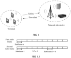
- the LTE RAT may be an LTE FDD (Frequency Division Dual, frequency division duplex) system, an LTE TDD (Time Division Duplexing, time division duplex) system, or a full-duplex system. Referring to FIG. 1, FIG. 1, FIG.
- the communications system includes at least one or more network side devices and one or more terminals.
- the terminal includes user equipment (User Equiment, UE), and the network side device includes a base station, a network controller, a mobile switching center, or the like.
- the terminal may communicate with the network side device, or may communicate with another terminal, for example, communicate in a D2D (device to device, device-to-device) scenario or an M2M (machine to machine, machine-to-machine) scenario.
- the network side device may communicate with the terminal, or may communicate with another network side device, for example, communication between a macro base station and an access point.
- a wireless network device (including a first wireless network device and a second wireless network device) includes the network side device and/or the terminal in the wireless communications system.
- An application scenario in which the first wireless network device is a base station and the second wireless network device is user equipment is used as an example to describe a communications system network architecture.
- Another case both the first wireless network device and the second wireless network device are user equipment, or both the first wireless network device and the second wireless network device are base stations, or the first wireless network device is user equipment and the second wireless network device is a base station) is similar to the application scenario. Details are not described in the embodiments.
- the base station includes various types of devices that can provide a base station function, for example, a device that provides the base station function in a 2G (2-Generation wireless telephone technology, 2-Generation telephone communications technology specification) network includes a BTS (base transceiver station, base transceiver station) and a BSC (base station controller, base station controller), a device that provides the base station function in a 3G (3rd-Generation, 3 rd Generation) network includes a NodeB (NodeB) and an RNC (radio network controller, radio network controller), a device that provides the base station function in a 4G (4th Generation mobile communication, 4 th Generation mobile communication) network includes an eNB (evolved NodeB, evolved NodeB), and a device that provides the base station function in a WLAN (Wireless LAN, wireless local area network) is an AP (Access Point, access point).
- the user equipment is a terminal device, and includes a movable terminal device and an immovable terminal device.
- the user equipment may be distributed in a network.
- the user equipment has different names in different networks, such as a terminal, a mobile station, a subscriber unit, a station, a cellular phone, a personal digital assistant, a wireless modem, a wireless communications device, a handheld device, a laptop computer, a cordless phone, or a wireless local loop station.
- the user equipment may communicate with one or more core networks by using an RAN (Radio Access Network, radio access network) (an access part of a wireless communications network), for example, exchange a voice and/or data with the radio access network.
- RAN Radio Access Network, radio access network
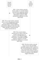
- a solution that supports cross-carrier physical random access channel PRACH scheduling transmission between user equipment and a base station and that is specified in an existing wireless communications protocol standard is described herein.
- a frame structure of a first radio frame on a first carrier is the same as a frame structure of a second radio frame on a second carrier.
- the UE If UE receives PRACH trigger information on a PDCCH (Physical Downlink Control Channel, physical downlink control channel), where the PRACH trigger information is carried in a first transmission subframe whose subframe number is Subframe n and that is in the first radio frame on the first carrier, the UE sends a random access preamble sequence to a base station in response to the received PRACH trigger information.
- the preamble sequence is carried in a second transmission subframe whose subframe number is Subframe i + k2 (k2 is greater than or equal to 6) and that is in the second radio frame on the second carrier, and a transmission subframe whose subframe number is Subframe i and the first transmission subframe whose subframe number is Subframe n are in a same time period.
- the "subframe” or the “transmission subframe” is a "time unit” or a “transmission time unit”.
- a structure, duration, or the like of a time unit in a time domain may be set according to a system requirement. This is not limited in this application.
- the time unit may be further directly defined as a symbol, a timeslot, a mini-slot, or the like, or include at least one symbol, at least one subframe, at least one timeslot, at least one mini-slot, or the like.
- the solution in this embodiment of the present invention may be applied to a time unit such as a symbol, a timeslot, or a mini-slot, or be applied to a time unit such as at least one symbol, at least one subframe, at least one timeslot, or at least one mini-slot.
- a specific implementation is the same as that performed when a subframe is used as the time unit. Details are not described.
- FIG. 2 is a schematic flowchart of a radio frame transmission method according to a method embodiment of the present invention.
- the radio frame transmission method includes the following steps. S201.
- a first wireless network device sends, to a second wireless network device, physical random access channel PRACH trigger information carried in a first transmission subframe in a first radio frame.
- the PRACH trigger information may be specifically a physical downlink control channel order PDCCH order.
- the second wireless network device receives the physical random access channel PRACH trigger information that is carried in the first transmission subframe in the first radio frame and that is sent by the first wireless network device.
- the second wireless network device sends, to the first wireless network device in response to the PRACH trigger information, a preamble sequence carried in a second transmission subframe in a second radio frame.
- the first wireless network device receives the preamble sequence that is carried in the second transmission subframe in the second radio frame and that is sent by the second wireless network device in response to the PRACH trigger information.
- the preset first mapping relationship may be pre-written by a developer into the second wireless network device and the first wireless network device, or be sent to the second wireless network device and the first wireless network device by another service device in a communications system, or the first wireless network device sends, to the second wireless network device, signaling that indicates the preset first mapping relationship, or the like.
- a specific manner of obtaining the first mapping relationship is not uniquely limited in this embodiment of the present invention.
- the second wireless network device and the first wireless network device transmit the first radio frame and the second radio frame
- the first wireless network device sends, to the second wireless network device, the PRACH trigger information carried in the first transmission subframe in the first radio frame, and after receiving the PRACH trigger information, based on a correspondence that is between the subframe number of the first transmission subframe and the subframe number of the second transmission subframe in the second radio frame and that is defined in the preset first mapping relationship and the subframe number of the received first transmission subframe
- the second wireless network device determines the subframe number of the second transmission subframe, and sends, to the first wireless network device, the preamble sequence carried in the second transmission subframe, so as to implement PRACH scheduling transmission between the second wireless network device and the first wireless network device.
- the structure of the transmission subframe in the first radio frame is different from the structure of the transmission subframe in the second radio frame. It can be learned that the wireless network devices in this solution can implement PRACH scheduling transmission between the wireless network devices based on cooperation
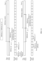
- FIG. 2.1 is an example diagram of a frame structure that is of a radio frame and that includes a first mapping relationship according to an embodiment of the present invention.
- a start moment and an end moment of the M1 transmission subframes and a start moment and an end moment of the first transmission subframe may not be totally synchronous.
- a transmission subframe corresponding to the start moment of the M1 transmission subframes that is, the first transmission subframe in the M1 transmission subframes, may be determined based on the following operation: obtaining the start moment of the first transmission subframe, and determining, as the first transmission subframe in the M1 transmission subframes, a transmission subframe whose start moment is the closest to the start moment of the first transmission subframe.
- FIG. 2.1-a is an example diagram of another frame structure that is of a radio frame and that includes a first mapping relationship according to an embodiment of the present invention.
- the first wireless network device after the first wireless network device receives the preamble sequence that is carried in the second transmission subframe in the second radio frame and that is sent by the second wireless network device in response to the PRACH trigger information,
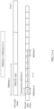
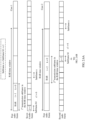
- FIG. 2.2 is an example diagram of a frame structure that is of a radio frame and that includes a second mapping relationship according to an embodiment of the present invention.
- FIG. 2.3 is an example diagram of another frame structure that is of a radio frame and that includes a second mapping relationship according to an embodiment of the present invention.
- the transmission time period of the second transmission subframe may overlap some transmission time periods of two adjacent transmission subframes in the first radio frame. In this case, it is necessary to determine that a subframe number of any one of the two transmission subframes is Subframe q1. It is assumed that subframe numbers of the two transmission subframes are respectively Subframe qla and Subframe qla + 1, a wireless network device may determine that the subframe number Subframe qla is Subframe q1, or determine that Subframe qla + 1 is Subframe q1. In addition, it should be noted that policies, preset in the first wireless network device and the second wireless network device, for determining the subframe number Subframe q1 need to be the same.
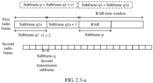
- FIG. 2.3-a is an example diagram of another frame structure that is of a radio frame and that includes a second mapping relationship according to an embodiment of the present invention.
- FIG. 2.4 is an example diagram of another frame structure that is of a radio frame and that includes a second mapping relationship according to an embodiment of the present invention.
- the transmission time period of the transmission subframe whose subframe number is Subframe q + w may overlap some transmission time periods of two adjacent transmission subframes in the first radio frame.
- subframe numbers of the two transmission subframes are respectively Subframe q2a and Subframe q2a + 1
- a wireless network device may determine that the subframe number Subframe q2a is Subframe q2
- a wireless network device may determine that Subframe q2a + 1 is Subframe q2.
- policies, preset in the first wireless network device and the second wireless network device, for determining the subframe number Subframe q2 need to be the same.
- FIG. 2.4-a is an example diagram of another frame structure that is of a radio frame and that includes a second mapping relationship according to an embodiment of the present invention.
- the first wireless network device after the first wireless network device receives the preamble sequence that is carried in the second transmission subframe in the second radio frame and that is sent by the second wireless network device in response to the PRACH trigger information,
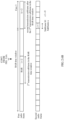
- FIG. 2.5 is an example diagram of a frame structure that is of a radio frame and that includes a third mapping relationship according to an embodiment of the present invention.
- the method further includes:
- FIG. 2.6A and FIG. 2.6B are an example diagram of a frame structure that is of a radio frame and that includes a fourth mapping relationship according to an embodiment of the present invention.
- a start moment of a subframe in the first radio frame and a start moment of a subframe in the second radio frame are not synchronous, a start moment and an end moment of the M2 transmission subframes and a start moment and an end moment of the first transmission subframe may not be totally synchronous.
- a transmission subframe corresponding to the start moment of the M2 transmission subframes may be determined based on the following operation: obtaining a start moment of the k th transmission subframe after the i th transmission subframe in the RAR time window, and determining, as the first transmission subframe in the M2 transmission subframes, a transmission subframe whose start moment is the closest to the start moment of the k th transmission subframe.
- FIG. 2.6-a is an example diagram of another frame structure that is of a radio frame and that includes a fourth mapping relationship according to an embodiment of the present invention.
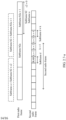
- FIG. 2.7 is an example diagram of a frame structure that is of a radio frame and that includes a fourth mapping relationship according to an embodiment of the present invention.
- the transmission time period of the transmission subframe whose subframe number is Subframe d + k may overlap some transmission time periods of two transmission subframes in the first radio frame.
- FIG. 2.7-a is an example diagram of another frame structure that is of a radio frame and that includes a second mapping relationship according to an embodiment of the present invention.
- a time location of the transmission subframe in a radio frame is determined once a subframe number of the transmission subframe is determined.
- Both the second wireless network device and the first wireless network device can determine the time location of the transmission subframe by determining the subframe number of the transmission subframe.
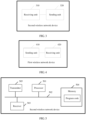
- FIG. 3 is a schematic structural diagram of a second wireless network device according to an embodiment of the present invention.
- the second wireless network device is the second wireless network device in the radio frame transmission method described in FIG. 2 .
- the second wireless network device in this embodiment of the present invention may include at least a receiving unit 310 and a sending unit 320.
- the receiving unit 310 is configured to receive physical random access channel PRACH trigger information that is carried in a first transmission subframe in a first radio frame and that is sent by a first wireless network device.
- the sending unit 320 is configured to send, to the first wireless network device in response to the PRACH trigger information, a preamble sequence carried in a second transmission subframe in a second radio frame.
- the second wireless network device further includes: a first detection unit, configured to detect, in a random access response RAR time window, an RAR sent by the first wireless network device, where the RAR sent by the first wireless network device is carried in a third transmission subframe, the RAR time window includes N transmission subframes, the third transmission subframe is any one of the N transmission subframes, and N is a positive integer.
- a first detection unit configured to detect, in a random access response RAR time window, an RAR sent by the first wireless network device, where the RAR sent by the first wireless network device is carried in a third transmission subframe, the RAR time window includes N transmission subframes, the third transmission subframe is any one of the N transmission subframes, and N is a positive integer.
- the second wireless network device further includes: a second detection unit, configured to detect, in a random access response RAR time window, an RAR sent by the first wireless network device, where the RAR sent by the first wireless network device is carried in a third transmission subframe, the RAR time window includes N transmission subframes, and N is a positive integer.
- a second detection unit configured to detect, in a random access response RAR time window, an RAR sent by the first wireless network device, where the RAR sent by the first wireless network device is carried in a third transmission subframe, the RAR time window includes N transmission subframes, and N is a positive integer.
- N is a positive integer.
- the first transmission subframe and M1 transmission subframes in the second radio frame are in a same time period, and M1 is an integer greater than 1;
- FIG. 4 is a schematic structural diagram of a first wireless network device according to an embodiment of the present invention.
- the first wireless network device is the first wireless network device in the radio frame transmission method described in FIG. 2 .
- the first wireless network device in this embodiment of the present invention may include at least a sending unit 410 and a receiving unit 420.
- the sending unit 410 is configured to send, to a second wireless network device, physical random access channel PRACH trigger information carried in a first transmission subframe in a first radio frame.
- the receiving unit 420 is configured to receive a preamble sequence that is carried in a second transmission subframe in a second radio frame and that is sent by the second wireless network device in response to the PRACH trigger information.
- the sending unit 410 is further configured to: send, to the second wireless network device, a random access response RAR carried in a third transmission subframe, where the third transmission subframe is any one of N transmission subframes, the N transmission subframes form an RAR time window used to detect the RAR, and N is a positive integer greater than 1.
- the sending unit 410 is further configured to: send, to the second wireless network device, a random access response RAR carried in a third transmission subframe, where the third transmission subframe is any one of N transmission subframes, the N transmission subframes form an RAR time window used to detect the RAR, and N is a positive integer greater than 1.
- RAR random access response
- the first transmission subframe and M1 transmission subframes in the second radio frame are in a same time period, and M1 is an integer greater than 1;
- FIG. 5 is a schematic structural diagram of another second wireless network device according to an embodiment of the present invention.
- the second wireless network device may include at least one processor 501 such as a CPU, at least one communications bus 502, at least one modem 503, a memory 504, and a wireless interface 505.
- the communications bus 502 is configured to implement connection and communication between these components.
- the wireless interface 505 is configured to perform signaling or data communication with another node device.
- the memory 504 may be a high-speed RAM, or may be a non-volatile memory (non-volatile memory), for example, at least one magnetic disk storage.
- the memory 504 may be at least one storage apparatus far away from the foregoing processor 501.
- the memory 504 stores a group of program code, and the processor 501 is configured to invoke the program code stored in the memory 504 to perform the following operations:
- the first transmission subframe and M1 transmission subframes in the second radio frame are in a same time period, and M1 is an integer greater than 1;
- the second wireless network device may be user equipment.
- FIG. 6 is a schematic structural diagram of another first wireless network device according to an embodiment of the present invention.
- the first wireless network device may include at least one processor 601 such as a CPU, at least one communications bus 602, at least one modem 603, a memory 604, and a wireless interface 605.
- the communications bus 602 is configured to implement connection and communication between these components.
- the wireless interface 605 is configured to perform signaling or data communication with another node device.
- the memory 604 may be a high-speed RAM, or may be a non-volatile memory (non-volatile memory), for example, at least one magnetic disk storage.
- the memory 604 may be at least one storage apparatus far away from the foregoing processor 601.
- the memory 604 stores a group of program code, and the processor 601 is configured to invoke the program code stored in the memory 604 to perform the following operations:
- the first transmission subframe and M1 transmission subframes in the second radio frame are in a same time period, and M1 is an integer greater than 1;
- the first wireless network device may be a base station.
- the program may be stored in a computer readable storage medium. When the program runs, the processes of the methods in the embodiments are performed.
- the foregoing storage medium may include: a magnetic disk, an optical disc, a read-only memory (Read-Only Memory, ROM), or a random access memory (Random Access Memory, RAM).
Landscapes
- Engineering & Computer Science (AREA)
- Computer Networks & Wireless Communication (AREA)
- Signal Processing (AREA)
- Mobile Radio Communication Systems (AREA)
Claims (15)
- Funkrahmenübertragungsverfahren, umfassend:Empfangen (S202) von Auslöseinformationen bezüglich eines physikalischen Direktzugriffskanals, PRACH, die in einer ersten Übertragungszeiteinheit in einem ersten Funkrahmen übertragen werden und die von einer ersten drahtlosen Netzwerkvorrichtung sind; undSenden (S203) einer Präambelsequenz, die in einer zweiten Übertragungszeiteinheit in einem zweiten Funkrahmen übertragen wird, als Reaktion auf die PRACH-Auslöseinformationen an die drahtlose Netzwerkvorrichtung, wobei es eine vorgegebene erste Zuordnungsbeziehung zwischen einer Zeiteinheitsnummer der ersten Übertragungszeiteinheit und einer Zeiteinheitsnummer der zweiten Übertragungszeiteinheit gibt, undwobei ein Unterträgerabstand des ersten Funkrahmens sich von einem Unterträgerabstand des zweiten Funkrahmens unterscheidet.
- Verfahren nach Anspruch 1, wobei das Verfahren nach dem Senden (S202) der Präambelsequenz, die in einer zweiten Übertragungszeiteinheit in einem zweiten Funkrahmen übertragen wird, an die drahtlose Netzwerkvorrichtung ferner umfasst:Erkennen in einem Direktzugriffsantwort-,RAR,-Zeitfenster einer RAR von der ersten drahtlosen Netzwerkvorrichtung, wobei die RAR von der drahtlosen Netzwerkvorrichtung in einer dritten Übertragungszeiteinheit übertragen wird, das RAR-Zeitfenster N Übertragungszeiteinheiten umfasst, die dritte Übertragungszeiteinheit eine beliebige der N Übertragungszeiteinheiten ist, und N eine positive ganze Zahl ist, wobeies eine vorgegebene zweite Zuordnungsbeziehung zwischen einer Zeiteinheitsnummer einer 1. Übertragungszeiteinheit im RAR-Zeitfenster und der Zeiteinheitsnummer der zweiten Übertragungszeiteinheit gibt.
- Verfahren nach Anspruch 2, wobeidie vorgegebene zweite Zuordnungsbeziehung die folgende Formel erfüllt: Zeiteinheit p = Zeiteinheit q + r, wobeiZeiteinheit p die Zeiteinheitsnummer der 1. Übertragungszeiteinheit im RAR-Zeitfenster ist, Zeiteinheit q die Zeiteinheitsnummer der zweiten Übertragungszeiteinheit ist, und r eine positive ganze Zahl ist; oderdie vorgegebene zweite Zuordnungsbeziehung die folgende Formel erfüllt: Zeiteinheit p = Zeiteinheit q1 + r1, wobeiZeiteinheit p die Zeiteinheitsnummer der 1. Übertragungszeiteinheit im RAR-Zeitfenster ist, Zeiteinheit q1 eine Zeiteinheitsnummer einer Übertragungszeiteinheit ist, die im ersten Funkrahmen ist und deren Übertragungszeitperiode eine erste Zeitperiode umfasst, wobei die erste Zeitperiode eine Übertragungszeitperiode der zweiten Übertragungszeiteinheit ist, und r1 eine positive ganze Zahl ist; oder die vorgegebene zweite Zuordnungsbeziehung die folgende Formel erfüllt: Zeiteinheit p = Zeiteinheit q2 + r2, wobeiZeiteinheit p die Zeiteinheitsnummer der 1. Übertragungszeiteinheit im RAR-Zeitfenster ist, Zeiteinheit q2 eine Zeiteinheitsnummer einer Übertragungszeiteinheit ist, die im ersten Funkrahmen ist und deren Übertragungszeitperiode eine zweite Zeitperiode umfasst, wobei die zweite Zeitperiode eine Übertragungszeitperiode einer Übertragungszeiteinheit ist, deren Zeiteinheitsnummer Zeiteinheit q + w ist, Zeiteinheit q die Zeiteinheitsnummer der zweiten Übertragungszeiteinheit ist, r2 eine positive ganze Zahl ist, und w eine positive ganze Zahl größer als 1 ist.
- Verfahren nach Anspruch 1, wobei
das Verfahren nach dem Senden (203) einer Präambelsequenz, die in einer zweiten Übertragungszeiteinheit in einem zweiten Funkrahmen übertragen wird, an die drahtlose Netzwerkvorrichtung ferner umfasst:Erkennen in einem Direktzugriffsantwort,RAR,-Zeitfenster einer RAR von der drahtlosen Netzwerkvorrichtung, wobei die RAR von der drahtlosen Netzwerkvorrichtung in einer dritten Übertragungszeiteinheit übertragen wird, das RAR-Zeitfenster N Übertragungszeiteinheiten umfasst, und N eine positive ganze Zahl ist, wobeies eine vorgegebene dritte Zuordnungsbeziehung zwischen einer Zeiteinheitsnummer der 1. Übertragungszeiteinheit im RAR-Zeitfenster und der Zeiteinheitsnummer der ersten Übertragungszeiteinheit gibt. - Verfahren nach Anspruch 4, wobeidie vorgegebene dritte Zuordnungsbeziehung die folgende Formel erfüllt: Zeiteinheit x = Zeiteinheit y + z, wobeiZeiteinheit x die Zeiteinheitsnummer der 1. Übertragungszeiteinheit im RAR-Zeitfenster ist, Zeiteinheit y die Zeiteinheitsnummer der ersten Übertragungszeiteinheit ist und ein Wert von z eine positive ganze Zahl ist.
- Verfahren nach einem der Ansprüche 2 bis 5, wobei das Verfahren ferner umfasst:Senden eines in einer vierten Übertragungszeiteinheit übertragenen Datenblocks eines gemeinsamen Uplink-Kanals, PUSCH, an die drahtlose Netzwerkvorrichtung, wenn erkannt wird, dass eine i-te Übertragungszeiteinheit im RAR-Zeitfenster Informationen bezüglich eines physikalischen Downlink-Steuerkanals, PDCCH, überträgt, die durch eine temporäre Direktzugriffsnetzwerkkennung, RA-RNTI, verwürfelt sind, und dass ein Downlink-Datenblock, der den PDCCH-Informationen entspricht, die Präambelsequenz umfasst, wobeies eine vorgegebene vierte Zuordnungsbeziehung zwischen einer Zeiteinheitsnummer der vierten Übertragungszeiteinheit und einer Zeiteinheitsnummer der i-ten Übertragungszeiteinheit im RAR-Zeitfenster gibt, und i eine positive ganze Zahl kleiner oder gleich N ist.
- Verfahren nach einem der Ansprüche 1 bis 6, wobei die Zeiteinheit ein Schlitz ist.
- Verfahren nach einem der Ansprüche 1 bis 7, wobei es sich bei den PRACH-Auslöseinformationen um einen Befehl auf einem physikalischen Downlink-Steuerkanal, PDCCH, handelt.
- Funkrahmenübertragungsverfahren, umfassend:Senden (S201) von Auslöseinformationen bezüglich eines physikalischen Direktzugriffskanals, PRACH, die in einer ersten Übertragungszeiteinheit in einem ersten Funkrahmen übertragen werden, von einer drahtlosen Netzwerkvorrichtung an ein Endgerät; undEmpfangen (S203) einer Präambelsequenz, die in einer zweiten Übertragungszeiteinheit in einem zweiten Funkrahmen übertragen wird, durch die drahtlose Netzwerkvorrichtung als Reaktion auf die PRACH-Auslöseinformationen, wobei es eine vorgegebene erste Zuordnungsbeziehung zwischen einer Zeiteinheitsnummer der ersten Übertragungszeiteinheit und einer Zeiteinheitsnummer der zweiten Übertragungszeiteinheit gibt, und ein Unterträgerabstand des ersten Funkrahmens sich von einem Unterträgerabstand des zweiten Funkrahmens unterscheidet.
- Verfahren nach Anspruch 9, wobei die Zeiteinheit ein Schlitz ist.
- Verfahren nach Anspruch 9 oder 10, wobei es sich bei den PRACH-Auslöseinformationen um einen Befehl auf einem physikalischen Downlink-Steuerkanals, PDCCH, handelt.
- Verfahren nach einem der Ansprüche 1-8 oder 9-11, wobei der erste Funkrahmen ein Funkrahmen eines ersten Trägers ist, der zweite Funkrahmen ein Funkrahmen eines zweiten Trägers ist, wobei ein Frequenzband des ersten Trägers sich von einem Frequenzband des zweiten Trägers unterscheidet, oder der erste Träger und der zweite Träger verschiedene Frequenzteilbänder, verschiedene Unterträger oder verschiedene Frequenzdomänenteile in einem gleichen Frequenzband sind.
- Verfahren nach Anspruch 12, wobei der erste Träger und der zweite Träger verschiedenen Funkrahmenstrukturen entsprechen, die verschiedene Unterträgerabstände, verschiedene zyklische Präfixe und/oder verschiedene Zeiteinheiten umfassen.
- Vorrichtung, umfassend einen Prozessor (501), einen Speicher (504) und eine Kommunikationsschnittstelle und einen Bus (502), wobei der Prozessor (501), die Kommunikationsschnittstelle und der Speicher (504) durch Verwenden des Busses (502) miteinander kommunizieren;der Speicher (504) ausführbaren Programmcode speichert; undder Prozessor (501) zum Aufrufen des im Speicher gespeicherten ausführbaren Programmcodes zum Durchführen des Verfahrens nach einem der Ansprüche 1-8, 12, 13 oder 9-13 konfiguriert ist.
- Computerlesbares Speichermedium, umfassend Anweisungen, die bei Ausführung durch einen Computer den Computer zum Ausführen der Schritte des Verfahrens nach einem der Ansprüche 1-8, 12, 13 oder 9-13 veranlassen.
Applications Claiming Priority (3)
| Application Number | Priority Date | Filing Date | Title |
|---|---|---|---|
| CN201510956990.0A CN106900072B (zh) | 2015-12-18 | 2015-12-18 | 一种无线帧的传输方法及无线网络设备 |
| EP16874880.4A EP3376816B1 (de) | 2015-12-18 | 2016-12-15 | Funkrahmenübertragungsverfahren und drahtlosnetzwerkvorrichtung |
| PCT/CN2016/110188 WO2017101823A1 (zh) | 2015-12-18 | 2016-12-15 | 一种无线帧的传输方法及无线网络设备 |
Related Parent Applications (1)
| Application Number | Title | Priority Date | Filing Date |
|---|---|---|---|
| EP16874880.4A Division EP3376816B1 (de) | 2015-12-18 | 2016-12-15 | Funkrahmenübertragungsverfahren und drahtlosnetzwerkvorrichtung |
Publications (2)
| Publication Number | Publication Date |
|---|---|
| EP3823402A1 EP3823402A1 (de) | 2021-05-19 |
| EP3823402B1 true EP3823402B1 (de) | 2023-11-08 |
Family
ID=59055852
Family Applications (2)
| Application Number | Title | Priority Date | Filing Date |
|---|---|---|---|
| EP16874880.4A Active EP3376816B1 (de) | 2015-12-18 | 2016-12-15 | Funkrahmenübertragungsverfahren und drahtlosnetzwerkvorrichtung |
| EP20191368.8A Active EP3823402B1 (de) | 2015-12-18 | 2016-12-15 | Funkrahmenübertragungsverfahren, vorrichtung und computerlesbares speichermedium |
Family Applications Before (1)
| Application Number | Title | Priority Date | Filing Date |
|---|---|---|---|
| EP16874880.4A Active EP3376816B1 (de) | 2015-12-18 | 2016-12-15 | Funkrahmenübertragungsverfahren und drahtlosnetzwerkvorrichtung |
Country Status (4)
| Country | Link |
|---|---|
| US (1) | US10405343B2 (de) |
| EP (2) | EP3376816B1 (de) |
| CN (2) | CN111225449A (de) |
| WO (1) | WO2017101823A1 (de) |
Families Citing this family (3)
| Publication number | Priority date | Publication date | Assignee | Title |
|---|---|---|---|---|
| EP3668250A4 (de) * | 2017-08-09 | 2021-04-21 | LG Electronics Inc. | Verfahren zur durchführung eines direktzugriffsverfahrens und vorrichtung dafür |
| CN109618410B (zh) * | 2017-08-10 | 2020-03-20 | 华为技术有限公司 | 通信方法和设备 |
| EP3841820B1 (de) * | 2019-11-13 | 2024-06-05 | Nokia Technologies Oy | Aufwecksignal mit direktzugriffsantwort |
Family Cites Families (9)
| Publication number | Priority date | Publication date | Assignee | Title |
|---|---|---|---|---|
| CN101841922B (zh) * | 2009-03-16 | 2015-01-28 | 中兴通讯股份有限公司 | 选择随机接入资源的方法及终端 |
| BRPI0925300B1 (pt) * | 2009-06-22 | 2021-01-12 | Alcatel Lucent | método para estabelecer a sincronização de uplink, estação base, equipamento do usuário, e sistema de comunicação |
| CN102202415B (zh) * | 2011-05-18 | 2019-01-22 | 中兴通讯股份有限公司 | 一种物理随机接入信道的传输方法和系统 |
| US9603048B2 (en) * | 2012-03-16 | 2017-03-21 | Interdigital Patent Holdings, Inc. | Random access procedures in wireless systems |
| CN103379072B (zh) * | 2012-04-20 | 2016-12-14 | 电信科学技术研究院 | 一种信号传输方法及装置 |
| CN103716895B (zh) * | 2012-09-29 | 2020-11-17 | 中兴通讯股份有限公司 | 物理随机接入信道的资源确定方法及装置 |
| CN103796330B (zh) * | 2012-11-02 | 2017-11-10 | 电信科学技术研究院 | 随机接入信道的传输及接收方法和设备 |
| CN103916974B (zh) * | 2013-01-07 | 2018-06-05 | 华为技术有限公司 | 一种前导序列的传输方法、装置及系统 |
| WO2015034301A1 (en) * | 2013-09-04 | 2015-03-12 | Lg Electronics Inc. | Method and apparatus for aggregation of frequency division duplex and time division duplex |
-
2015
- 2015-12-18 CN CN202010072417.4A patent/CN111225449A/zh active Pending
- 2015-12-18 CN CN201510956990.0A patent/CN106900072B/zh active Active
-
2016
- 2016-12-15 EP EP16874880.4A patent/EP3376816B1/de active Active
- 2016-12-15 WO PCT/CN2016/110188 patent/WO2017101823A1/zh not_active Ceased
- 2016-12-15 EP EP20191368.8A patent/EP3823402B1/de active Active
-
2018
- 2018-06-18 US US16/011,128 patent/US10405343B2/en active Active
Also Published As
| Publication number | Publication date |
|---|---|
| EP3376816B1 (de) | 2020-09-09 |
| CN106900072B (zh) | 2020-02-14 |
| EP3823402A1 (de) | 2021-05-19 |
| US20180302921A1 (en) | 2018-10-18 |
| EP3376816A4 (de) | 2018-11-21 |
| EP3376816A1 (de) | 2018-09-19 |
| US10405343B2 (en) | 2019-09-03 |
| CN111225449A (zh) | 2020-06-02 |
| CN106900072A (zh) | 2017-06-27 |
| WO2017101823A1 (zh) | 2017-06-22 |
Similar Documents
| Publication | Publication Date | Title |
|---|---|---|
| US12408198B2 (en) | Random access backoff indicator | |
| EP3294031B1 (de) | Drahtlose vorrichtung, erster netzwerkknoten und verfahren darin | |
| JP7643500B2 (ja) | 2ステップランダムアクセスにおけるランダムアクセスレスポンスの受送信方法及び装置 | |
| US11706005B2 (en) | Uplink reference signal sending method, uplink reference signal receiving method, and apparatus | |
| US11122630B2 (en) | Information sending method and apparatus and information receiving method and apparatus | |
| CN105580483A (zh) | 无线通信终端、无线基站以及无线通信方法 | |
| CN118633345A (zh) | 覆盖增强方法及相关设备 | |
| US10405343B2 (en) | Radio frame transmission method and wireless network device | |
| JP2024069386A (ja) | アップリンク伝送方法及び装置 | |
| US20180324799A1 (en) | Radio frame transmission method and wireless network device | |
| CN118556447A (zh) | 覆盖增强方法及相关设备 | |
| CN111082906B (zh) | 一种特殊小区的prach配置方法和设备 | |
| CN110972250B (zh) | 一种功率控制方法及装置 | |
| AU2016405421A1 (en) | Uplink transmission method and device based on licensed-assisted access (LAA) system | |
| WO2025035332A1 (zh) | 信息接收方法、信息发送方法以及装置 | |
| JP2022101664A (ja) | ユーザ装置及び基地局により実行される方法 |
Legal Events
| Date | Code | Title | Description |
|---|---|---|---|
| PUAI | Public reference made under article 153(3) epc to a published international application that has entered the european phase |
Free format text: ORIGINAL CODE: 0009012 |
|
| STAA | Information on the status of an ep patent application or granted ep patent |
Free format text: STATUS: THE APPLICATION HAS BEEN PUBLISHED |
|
| AC | Divisional application: reference to earlier application |
Ref document number: 3376816 Country of ref document: EP Kind code of ref document: P |
|
| AK | Designated contracting states |
Kind code of ref document: A1 Designated state(s): AL AT BE BG CH CY CZ DE DK EE ES FI FR GB GR HR HU IE IS IT LI LT LU LV MC MK MT NL NO PL PT RO RS SE SI SK SM TR |
|
| STAA | Information on the status of an ep patent application or granted ep patent |
Free format text: STATUS: REQUEST FOR EXAMINATION WAS MADE |
|
| 17P | Request for examination filed |
Effective date: 20211115 |
|
| RBV | Designated contracting states (corrected) |
Designated state(s): AL AT BE BG CH CY CZ DE DK EE ES FI FR GB GR HR HU IE IS IT LI LT LU LV MC MK MT NL NO PL PT RO RS SE SI SK SM TR |
|
| RIC1 | Information provided on ipc code assigned before grant |
Ipc: H04W 74/08 20090101ALN20230329BHEP Ipc: H04W 74/00 20090101AFI20230329BHEP |
|
| GRAP | Despatch of communication of intention to grant a patent |
Free format text: ORIGINAL CODE: EPIDOSNIGR1 |
|
| STAA | Information on the status of an ep patent application or granted ep patent |
Free format text: STATUS: GRANT OF PATENT IS INTENDED |
|
| RIC1 | Information provided on ipc code assigned before grant |
Ipc: H04W 74/08 20090101ALN20230425BHEP Ipc: H04W 74/00 20090101AFI20230425BHEP |
|
| INTG | Intention to grant announced |
Effective date: 20230523 |
|
| GRAS | Grant fee paid |
Free format text: ORIGINAL CODE: EPIDOSNIGR3 |
|
| GRAA | (expected) grant |
Free format text: ORIGINAL CODE: 0009210 |
|
| STAA | Information on the status of an ep patent application or granted ep patent |
Free format text: STATUS: THE PATENT HAS BEEN GRANTED |
|
| AC | Divisional application: reference to earlier application |
Ref document number: 3376816 Country of ref document: EP Kind code of ref document: P |
|
| AK | Designated contracting states |
Kind code of ref document: B1 Designated state(s): AL AT BE BG CH CY CZ DE DK EE ES FI FR GB GR HR HU IE IS IT LI LT LU LV MC MK MT NL NO PL PT RO RS SE SI SK SM TR |
|
| REG | Reference to a national code |
Ref country code: GB Ref legal event code: FG4D |
|
| REG | Reference to a national code |
Ref country code: CH Ref legal event code: EP |
|
| REG | Reference to a national code |
Ref country code: DE Ref legal event code: R096 Ref document number: 602016084086 Country of ref document: DE |
|
| REG | Reference to a national code |
Ref country code: IE Ref legal event code: FG4D |
|
| REG | Reference to a national code |
Ref country code: LT Ref legal event code: MG9D |
|
| REG | Reference to a national code |
Ref country code: NL Ref legal event code: MP Effective date: 20231108 |
|
| PG25 | Lapsed in a contracting state [announced via postgrant information from national office to epo] |
Ref country code: GR Free format text: LAPSE BECAUSE OF FAILURE TO SUBMIT A TRANSLATION OF THE DESCRIPTION OR TO PAY THE FEE WITHIN THE PRESCRIBED TIME-LIMIT Effective date: 20240209 |
|
| PG25 | Lapsed in a contracting state [announced via postgrant information from national office to epo] |
Ref country code: IS Free format text: LAPSE BECAUSE OF FAILURE TO SUBMIT A TRANSLATION OF THE DESCRIPTION OR TO PAY THE FEE WITHIN THE PRESCRIBED TIME-LIMIT Effective date: 20240308 |
|
| PG25 | Lapsed in a contracting state [announced via postgrant information from national office to epo] |
Ref country code: LT Free format text: LAPSE BECAUSE OF FAILURE TO SUBMIT A TRANSLATION OF THE DESCRIPTION OR TO PAY THE FEE WITHIN THE PRESCRIBED TIME-LIMIT Effective date: 20231108 |
|
| REG | Reference to a national code |
Ref country code: AT Ref legal event code: MK05 Ref document number: 1630798 Country of ref document: AT Kind code of ref document: T Effective date: 20231108 |
|
| PG25 | Lapsed in a contracting state [announced via postgrant information from national office to epo] |
Ref country code: NL Free format text: LAPSE BECAUSE OF FAILURE TO SUBMIT A TRANSLATION OF THE DESCRIPTION OR TO PAY THE FEE WITHIN THE PRESCRIBED TIME-LIMIT Effective date: 20231108 |
|
| PG25 | Lapsed in a contracting state [announced via postgrant information from national office to epo] |
Ref country code: AT Free format text: LAPSE BECAUSE OF FAILURE TO SUBMIT A TRANSLATION OF THE DESCRIPTION OR TO PAY THE FEE WITHIN THE PRESCRIBED TIME-LIMIT Effective date: 20231108 |
|
| PG25 | Lapsed in a contracting state [announced via postgrant information from national office to epo] |
Ref country code: ES Free format text: LAPSE BECAUSE OF FAILURE TO SUBMIT A TRANSLATION OF THE DESCRIPTION OR TO PAY THE FEE WITHIN THE PRESCRIBED TIME-LIMIT Effective date: 20231108 |
|
| PG25 | Lapsed in a contracting state [announced via postgrant information from national office to epo] |
Ref country code: NL Free format text: LAPSE BECAUSE OF FAILURE TO SUBMIT A TRANSLATION OF THE DESCRIPTION OR TO PAY THE FEE WITHIN THE PRESCRIBED TIME-LIMIT Effective date: 20231108 Ref country code: LT Free format text: LAPSE BECAUSE OF FAILURE TO SUBMIT A TRANSLATION OF THE DESCRIPTION OR TO PAY THE FEE WITHIN THE PRESCRIBED TIME-LIMIT Effective date: 20231108 Ref country code: IS Free format text: LAPSE BECAUSE OF FAILURE TO SUBMIT A TRANSLATION OF THE DESCRIPTION OR TO PAY THE FEE WITHIN THE PRESCRIBED TIME-LIMIT Effective date: 20240308 Ref country code: GR Free format text: LAPSE BECAUSE OF FAILURE TO SUBMIT A TRANSLATION OF THE DESCRIPTION OR TO PAY THE FEE WITHIN THE PRESCRIBED TIME-LIMIT Effective date: 20240209 Ref country code: ES Free format text: LAPSE BECAUSE OF FAILURE TO SUBMIT A TRANSLATION OF THE DESCRIPTION OR TO PAY THE FEE WITHIN THE PRESCRIBED TIME-LIMIT Effective date: 20231108 Ref country code: BG Free format text: LAPSE BECAUSE OF FAILURE TO SUBMIT A TRANSLATION OF THE DESCRIPTION OR TO PAY THE FEE WITHIN THE PRESCRIBED TIME-LIMIT Effective date: 20240208 Ref country code: AT Free format text: LAPSE BECAUSE OF FAILURE TO SUBMIT A TRANSLATION OF THE DESCRIPTION OR TO PAY THE FEE WITHIN THE PRESCRIBED TIME-LIMIT Effective date: 20231108 Ref country code: PT Free format text: LAPSE BECAUSE OF FAILURE TO SUBMIT A TRANSLATION OF THE DESCRIPTION OR TO PAY THE FEE WITHIN THE PRESCRIBED TIME-LIMIT Effective date: 20240308 |
|
| PG25 | Lapsed in a contracting state [announced via postgrant information from national office to epo] |
Ref country code: SE Free format text: LAPSE BECAUSE OF FAILURE TO SUBMIT A TRANSLATION OF THE DESCRIPTION OR TO PAY THE FEE WITHIN THE PRESCRIBED TIME-LIMIT Effective date: 20231108 Ref country code: RS Free format text: LAPSE BECAUSE OF FAILURE TO SUBMIT A TRANSLATION OF THE DESCRIPTION OR TO PAY THE FEE WITHIN THE PRESCRIBED TIME-LIMIT Effective date: 20231108 Ref country code: PL Free format text: LAPSE BECAUSE OF FAILURE TO SUBMIT A TRANSLATION OF THE DESCRIPTION OR TO PAY THE FEE WITHIN THE PRESCRIBED TIME-LIMIT Effective date: 20231108 Ref country code: NO Free format text: LAPSE BECAUSE OF FAILURE TO SUBMIT A TRANSLATION OF THE DESCRIPTION OR TO PAY THE FEE WITHIN THE PRESCRIBED TIME-LIMIT Effective date: 20240208 Ref country code: LV Free format text: LAPSE BECAUSE OF FAILURE TO SUBMIT A TRANSLATION OF THE DESCRIPTION OR TO PAY THE FEE WITHIN THE PRESCRIBED TIME-LIMIT Effective date: 20231108 Ref country code: HR Free format text: LAPSE BECAUSE OF FAILURE TO SUBMIT A TRANSLATION OF THE DESCRIPTION OR TO PAY THE FEE WITHIN THE PRESCRIBED TIME-LIMIT Effective date: 20231108 |
|
| PG25 | Lapsed in a contracting state [announced via postgrant information from national office to epo] |
Ref country code: DK Free format text: LAPSE BECAUSE OF FAILURE TO SUBMIT A TRANSLATION OF THE DESCRIPTION OR TO PAY THE FEE WITHIN THE PRESCRIBED TIME-LIMIT Effective date: 20231108 |
|
| PG25 | Lapsed in a contracting state [announced via postgrant information from national office to epo] |
Ref country code: CZ Free format text: LAPSE BECAUSE OF FAILURE TO SUBMIT A TRANSLATION OF THE DESCRIPTION OR TO PAY THE FEE WITHIN THE PRESCRIBED TIME-LIMIT Effective date: 20231108 |
|
| PG25 | Lapsed in a contracting state [announced via postgrant information from national office to epo] |
Ref country code: SK Free format text: LAPSE BECAUSE OF FAILURE TO SUBMIT A TRANSLATION OF THE DESCRIPTION OR TO PAY THE FEE WITHIN THE PRESCRIBED TIME-LIMIT Effective date: 20231108 |
|
| PG25 | Lapsed in a contracting state [announced via postgrant information from national office to epo] |
Ref country code: SM Free format text: LAPSE BECAUSE OF FAILURE TO SUBMIT A TRANSLATION OF THE DESCRIPTION OR TO PAY THE FEE WITHIN THE PRESCRIBED TIME-LIMIT Effective date: 20231108 Ref country code: SK Free format text: LAPSE BECAUSE OF FAILURE TO SUBMIT A TRANSLATION OF THE DESCRIPTION OR TO PAY THE FEE WITHIN THE PRESCRIBED TIME-LIMIT Effective date: 20231108 Ref country code: RO Free format text: LAPSE BECAUSE OF FAILURE TO SUBMIT A TRANSLATION OF THE DESCRIPTION OR TO PAY THE FEE WITHIN THE PRESCRIBED TIME-LIMIT Effective date: 20231108 Ref country code: IT Free format text: LAPSE BECAUSE OF FAILURE TO SUBMIT A TRANSLATION OF THE DESCRIPTION OR TO PAY THE FEE WITHIN THE PRESCRIBED TIME-LIMIT Effective date: 20231108 Ref country code: EE Free format text: LAPSE BECAUSE OF FAILURE TO SUBMIT A TRANSLATION OF THE DESCRIPTION OR TO PAY THE FEE WITHIN THE PRESCRIBED TIME-LIMIT Effective date: 20231108 Ref country code: DK Free format text: LAPSE BECAUSE OF FAILURE TO SUBMIT A TRANSLATION OF THE DESCRIPTION OR TO PAY THE FEE WITHIN THE PRESCRIBED TIME-LIMIT Effective date: 20231108 Ref country code: CZ Free format text: LAPSE BECAUSE OF FAILURE TO SUBMIT A TRANSLATION OF THE DESCRIPTION OR TO PAY THE FEE WITHIN THE PRESCRIBED TIME-LIMIT Effective date: 20231108 |
|
| REG | Reference to a national code |
Ref country code: CH Ref legal event code: PL |
|
| REG | Reference to a national code |
Ref country code: DE Ref legal event code: R097 Ref document number: 602016084086 Country of ref document: DE |
|
| PG25 | Lapsed in a contracting state [announced via postgrant information from national office to epo] |
Ref country code: LU Free format text: LAPSE BECAUSE OF NON-PAYMENT OF DUE FEES Effective date: 20231215 |
|
| PG25 | Lapsed in a contracting state [announced via postgrant information from national office to epo] |
Ref country code: MC Free format text: LAPSE BECAUSE OF FAILURE TO SUBMIT A TRANSLATION OF THE DESCRIPTION OR TO PAY THE FEE WITHIN THE PRESCRIBED TIME-LIMIT Effective date: 20231108 |
|
| REG | Reference to a national code |
Ref country code: BE Ref legal event code: MM Effective date: 20231231 |
|
| PG25 | Lapsed in a contracting state [announced via postgrant information from national office to epo] |
Ref country code: MC Free format text: LAPSE BECAUSE OF FAILURE TO SUBMIT A TRANSLATION OF THE DESCRIPTION OR TO PAY THE FEE WITHIN THE PRESCRIBED TIME-LIMIT Effective date: 20231108 Ref country code: LU Free format text: LAPSE BECAUSE OF NON-PAYMENT OF DUE FEES Effective date: 20231215 |
|
| PLBE | No opposition filed within time limit |
Free format text: ORIGINAL CODE: 0009261 |
|
| STAA | Information on the status of an ep patent application or granted ep patent |
Free format text: STATUS: NO OPPOSITION FILED WITHIN TIME LIMIT |
|
| REG | Reference to a national code |
Ref country code: IE Ref legal event code: MM4A |
|
| PG25 | Lapsed in a contracting state [announced via postgrant information from national office to epo] |
Ref country code: IE Free format text: LAPSE BECAUSE OF NON-PAYMENT OF DUE FEES Effective date: 20231215 |
|
| PG25 | Lapsed in a contracting state [announced via postgrant information from national office to epo] |
Ref country code: BE Free format text: LAPSE BECAUSE OF NON-PAYMENT OF DUE FEES Effective date: 20231231 |
|
| 26N | No opposition filed |
Effective date: 20240809 |
|
| PG25 | Lapsed in a contracting state [announced via postgrant information from national office to epo] |
Ref country code: CH Free format text: LAPSE BECAUSE OF NON-PAYMENT OF DUE FEES Effective date: 20231231 |
|
| PG25 | Lapsed in a contracting state [announced via postgrant information from national office to epo] |
Ref country code: SI Free format text: LAPSE BECAUSE OF FAILURE TO SUBMIT A TRANSLATION OF THE DESCRIPTION OR TO PAY THE FEE WITHIN THE PRESCRIBED TIME-LIMIT Effective date: 20231108 |
|
| PG25 | Lapsed in a contracting state [announced via postgrant information from national office to epo] |
Ref country code: SI Free format text: LAPSE BECAUSE OF FAILURE TO SUBMIT A TRANSLATION OF THE DESCRIPTION OR TO PAY THE FEE WITHIN THE PRESCRIBED TIME-LIMIT Effective date: 20231108 Ref country code: IE Free format text: LAPSE BECAUSE OF NON-PAYMENT OF DUE FEES Effective date: 20231215 Ref country code: CH Free format text: LAPSE BECAUSE OF NON-PAYMENT OF DUE FEES Effective date: 20231231 Ref country code: BE Free format text: LAPSE BECAUSE OF NON-PAYMENT OF DUE FEES Effective date: 20231231 |
|
| PG25 | Lapsed in a contracting state [announced via postgrant information from national office to epo] |
Ref country code: FI Free format text: LAPSE BECAUSE OF FAILURE TO SUBMIT A TRANSLATION OF THE DESCRIPTION OR TO PAY THE FEE WITHIN THE PRESCRIBED TIME-LIMIT Effective date: 20231108 |
|
| PG25 | Lapsed in a contracting state [announced via postgrant information from national office to epo] |
Ref country code: CY Free format text: LAPSE BECAUSE OF FAILURE TO SUBMIT A TRANSLATION OF THE DESCRIPTION OR TO PAY THE FEE WITHIN THE PRESCRIBED TIME-LIMIT; INVALID AB INITIO Effective date: 20161215 |
|
| PG25 | Lapsed in a contracting state [announced via postgrant information from national office to epo] |
Ref country code: HU Free format text: LAPSE BECAUSE OF FAILURE TO SUBMIT A TRANSLATION OF THE DESCRIPTION OR TO PAY THE FEE WITHIN THE PRESCRIBED TIME-LIMIT; INVALID AB INITIO Effective date: 20161215 |
|
| PG25 | Lapsed in a contracting state [announced via postgrant information from national office to epo] |
Ref country code: TR Free format text: LAPSE BECAUSE OF FAILURE TO SUBMIT A TRANSLATION OF THE DESCRIPTION OR TO PAY THE FEE WITHIN THE PRESCRIBED TIME-LIMIT Effective date: 20231108 |
|
| PGFP | Annual fee paid to national office [announced via postgrant information from national office to epo] |
Ref country code: DE Payment date: 20251104 Year of fee payment: 10 |
|
| PGFP | Annual fee paid to national office [announced via postgrant information from national office to epo] |
Ref country code: GB Payment date: 20251030 Year of fee payment: 10 |
|
| PGFP | Annual fee paid to national office [announced via postgrant information from national office to epo] |
Ref country code: FR Payment date: 20251110 Year of fee payment: 10 |