EP3823287A1 - Information processing device, information processing method, and program - Google Patents
Information processing device, information processing method, and program Download PDFInfo
- Publication number
- EP3823287A1 EP3823287A1 EP19835094.4A EP19835094A EP3823287A1 EP 3823287 A1 EP3823287 A1 EP 3823287A1 EP 19835094 A EP19835094 A EP 19835094A EP 3823287 A1 EP3823287 A1 EP 3823287A1
- Authority
- EP
- European Patent Office
- Prior art keywords
- virtual viewpoint
- playback speed
- viewpoint image
- camera
- virtual
- Prior art date
- Legal status (The legal status is an assumption and is not a legal conclusion. Google has not performed a legal analysis and makes no representation as to the accuracy of the status listed.)
- Pending
Links
- 230000010365 information processing Effects 0.000 title claims description 54
- 238000003672 processing method Methods 0.000 title claims description 6
- 230000035945 sensitivity Effects 0.000 claims description 4
- 230000002123 temporal effect Effects 0.000 claims description 3
- 238000000034 method Methods 0.000 description 28
- 238000004364 calculation method Methods 0.000 description 25
- 230000006870 function Effects 0.000 description 11
- 238000010586 diagram Methods 0.000 description 8
- 230000003247 decreasing effect Effects 0.000 description 6
- 230000015654 memory Effects 0.000 description 6
- 238000004590 computer program Methods 0.000 description 3
- 238000003825 pressing Methods 0.000 description 3
- 241000238631 Hexapoda Species 0.000 description 2
- 241001465754 Metazoa Species 0.000 description 2
- 230000001360 synchronised effect Effects 0.000 description 2
- 230000007423 decrease Effects 0.000 description 1
- 230000000694 effects Effects 0.000 description 1
- 238000009434 installation Methods 0.000 description 1
- 230000002441 reversible effect Effects 0.000 description 1
- 230000000007 visual effect Effects 0.000 description 1
Images


Classifications
-
- H—ELECTRICITY
- H04—ELECTRIC COMMUNICATION TECHNIQUE
- H04N—PICTORIAL COMMUNICATION, e.g. TELEVISION
- H04N5/00—Details of television systems
- H04N5/76—Television signal recording
- H04N5/765—Interface circuits between an apparatus for recording and another apparatus
- H04N5/77—Interface circuits between an apparatus for recording and another apparatus between a recording apparatus and a television camera
-
- H—ELECTRICITY
- H04—ELECTRIC COMMUNICATION TECHNIQUE
- H04N—PICTORIAL COMMUNICATION, e.g. TELEVISION
- H04N13/00—Stereoscopic video systems; Multi-view video systems; Details thereof
- H04N13/20—Image signal generators
- H04N13/282—Image signal generators for generating image signals corresponding to three or more geometrical viewpoints, e.g. multi-view systems
-
- H—ELECTRICITY
- H04—ELECTRIC COMMUNICATION TECHNIQUE
- H04N—PICTORIAL COMMUNICATION, e.g. TELEVISION
- H04N21/00—Selective content distribution, e.g. interactive television or video on demand [VOD]
- H04N21/40—Client devices specifically adapted for the reception of or interaction with content, e.g. set-top-box [STB]; Operations thereof
- H04N21/47—End-user applications
- H04N21/472—End-user interface for requesting content, additional data or services; End-user interface for interacting with content, e.g. for content reservation or setting reminders, for requesting event notification, for manipulating displayed content
- H04N21/47217—End-user interface for requesting content, additional data or services; End-user interface for interacting with content, e.g. for content reservation or setting reminders, for requesting event notification, for manipulating displayed content for controlling playback functions for recorded or on-demand content, e.g. using progress bars, mode or play-point indicators or bookmarks
-
- G—PHYSICS
- G11—INFORMATION STORAGE
- G11B—INFORMATION STORAGE BASED ON RELATIVE MOVEMENT BETWEEN RECORD CARRIER AND TRANSDUCER
- G11B27/00—Editing; Indexing; Addressing; Timing or synchronising; Monitoring; Measuring tape travel
- G11B27/02—Editing, e.g. varying the order of information signals recorded on, or reproduced from, record carriers
- G11B27/031—Electronic editing of digitised analogue information signals, e.g. audio or video signals
-
- G—PHYSICS
- G11—INFORMATION STORAGE
- G11B—INFORMATION STORAGE BASED ON RELATIVE MOVEMENT BETWEEN RECORD CARRIER AND TRANSDUCER
- G11B27/00—Editing; Indexing; Addressing; Timing or synchronising; Monitoring; Measuring tape travel
- G11B27/10—Indexing; Addressing; Timing or synchronising; Measuring tape travel
- G11B27/102—Programmed access in sequence to addressed parts of tracks of operating record carriers
- G11B27/105—Programmed access in sequence to addressed parts of tracks of operating record carriers of operating discs
-
- H—ELECTRICITY
- H04—ELECTRIC COMMUNICATION TECHNIQUE
- H04N—PICTORIAL COMMUNICATION, e.g. TELEVISION
- H04N13/00—Stereoscopic video systems; Multi-view video systems; Details thereof
- H04N13/20—Image signal generators
- H04N13/296—Synchronisation thereof; Control thereof
-
- H—ELECTRICITY
- H04—ELECTRIC COMMUNICATION TECHNIQUE
- H04N—PICTORIAL COMMUNICATION, e.g. TELEVISION
- H04N21/00—Selective content distribution, e.g. interactive television or video on demand [VOD]
- H04N21/20—Servers specifically adapted for the distribution of content, e.g. VOD servers; Operations thereof
- H04N21/21—Server components or server architectures
- H04N21/218—Source of audio or video content, e.g. local disk arrays
- H04N21/21805—Source of audio or video content, e.g. local disk arrays enabling multiple viewpoints, e.g. using a plurality of cameras
-
- H—ELECTRICITY
- H04—ELECTRIC COMMUNICATION TECHNIQUE
- H04N—PICTORIAL COMMUNICATION, e.g. TELEVISION
- H04N21/00—Selective content distribution, e.g. interactive television or video on demand [VOD]
- H04N21/20—Servers specifically adapted for the distribution of content, e.g. VOD servers; Operations thereof
- H04N21/23—Processing of content or additional data; Elementary server operations; Server middleware
- H04N21/234—Processing of video elementary streams, e.g. splicing of video streams or manipulating encoded video stream scene graphs
- H04N21/2343—Processing of video elementary streams, e.g. splicing of video streams or manipulating encoded video stream scene graphs involving reformatting operations of video signals for distribution or compliance with end-user requests or end-user device requirements
- H04N21/234381—Processing of video elementary streams, e.g. splicing of video streams or manipulating encoded video stream scene graphs involving reformatting operations of video signals for distribution or compliance with end-user requests or end-user device requirements by altering the temporal resolution, e.g. decreasing the frame rate by frame skipping
-
- H—ELECTRICITY
- H04—ELECTRIC COMMUNICATION TECHNIQUE
- H04N—PICTORIAL COMMUNICATION, e.g. TELEVISION
- H04N21/00—Selective content distribution, e.g. interactive television or video on demand [VOD]
- H04N21/40—Client devices specifically adapted for the reception of or interaction with content, e.g. set-top-box [STB]; Operations thereof
- H04N21/47—End-user applications
- H04N21/472—End-user interface for requesting content, additional data or services; End-user interface for interacting with content, e.g. for content reservation or setting reminders, for requesting event notification, for manipulating displayed content
- H04N21/47202—End-user interface for requesting content, additional data or services; End-user interface for interacting with content, e.g. for content reservation or setting reminders, for requesting event notification, for manipulating displayed content for requesting content on demand, e.g. video on demand
-
- H—ELECTRICITY
- H04—ELECTRIC COMMUNICATION TECHNIQUE
- H04N—PICTORIAL COMMUNICATION, e.g. TELEVISION
- H04N21/00—Selective content distribution, e.g. interactive television or video on demand [VOD]
- H04N21/40—Client devices specifically adapted for the reception of or interaction with content, e.g. set-top-box [STB]; Operations thereof
- H04N21/47—End-user applications
- H04N21/472—End-user interface for requesting content, additional data or services; End-user interface for interacting with content, e.g. for content reservation or setting reminders, for requesting event notification, for manipulating displayed content
- H04N21/47205—End-user interface for requesting content, additional data or services; End-user interface for interacting with content, e.g. for content reservation or setting reminders, for requesting event notification, for manipulating displayed content for manipulating displayed content, e.g. interacting with MPEG-4 objects, editing locally
-
- H—ELECTRICITY
- H04—ELECTRIC COMMUNICATION TECHNIQUE
- H04N—PICTORIAL COMMUNICATION, e.g. TELEVISION
- H04N21/00—Selective content distribution, e.g. interactive television or video on demand [VOD]
- H04N21/40—Client devices specifically adapted for the reception of or interaction with content, e.g. set-top-box [STB]; Operations thereof
- H04N21/47—End-user applications
- H04N21/472—End-user interface for requesting content, additional data or services; End-user interface for interacting with content, e.g. for content reservation or setting reminders, for requesting event notification, for manipulating displayed content
- H04N21/4728—End-user interface for requesting content, additional data or services; End-user interface for interacting with content, e.g. for content reservation or setting reminders, for requesting event notification, for manipulating displayed content for selecting a Region Of Interest [ROI], e.g. for requesting a higher resolution version of a selected region
-
- H—ELECTRICITY
- H04—ELECTRIC COMMUNICATION TECHNIQUE
- H04N—PICTORIAL COMMUNICATION, e.g. TELEVISION
- H04N21/00—Selective content distribution, e.g. interactive television or video on demand [VOD]
- H04N21/80—Generation or processing of content or additional data by content creator independently of the distribution process; Content per se
- H04N21/81—Monomedia components thereof
- H04N21/816—Monomedia components thereof involving special video data, e.g 3D video
-
- H—ELECTRICITY
- H04—ELECTRIC COMMUNICATION TECHNIQUE
- H04N—PICTORIAL COMMUNICATION, e.g. TELEVISION
- H04N21/00—Selective content distribution, e.g. interactive television or video on demand [VOD]
- H04N21/80—Generation or processing of content or additional data by content creator independently of the distribution process; Content per se
- H04N21/85—Assembly of content; Generation of multimedia applications
- H04N21/854—Content authoring
-
- H—ELECTRICITY
- H04—ELECTRIC COMMUNICATION TECHNIQUE
- H04N—PICTORIAL COMMUNICATION, e.g. TELEVISION
- H04N23/00—Cameras or camera modules comprising electronic image sensors; Control thereof
- H04N23/60—Control of cameras or camera modules
- H04N23/63—Control of cameras or camera modules by using electronic viewfinders
-
- H—ELECTRICITY
- H04—ELECTRIC COMMUNICATION TECHNIQUE
- H04N—PICTORIAL COMMUNICATION, e.g. TELEVISION
- H04N23/00—Cameras or camera modules comprising electronic image sensors; Control thereof
- H04N23/90—Arrangement of cameras or camera modules, e.g. multiple cameras in TV studios or sports stadiums
-
- H—ELECTRICITY
- H04—ELECTRIC COMMUNICATION TECHNIQUE
- H04N—PICTORIAL COMMUNICATION, e.g. TELEVISION
- H04N5/00—Details of television systems
- H04N5/222—Studio circuitry; Studio devices; Studio equipment
- H04N5/2224—Studio circuitry; Studio devices; Studio equipment related to virtual studio applications
-
- H—ELECTRICITY
- H04—ELECTRIC COMMUNICATION TECHNIQUE
- H04N—PICTORIAL COMMUNICATION, e.g. TELEVISION
- H04N5/00—Details of television systems
- H04N5/222—Studio circuitry; Studio devices; Studio equipment
- H04N5/262—Studio circuits, e.g. for mixing, switching-over, change of character of image, other special effects ; Cameras specially adapted for the electronic generation of special effects
- H04N5/2625—Studio circuits, e.g. for mixing, switching-over, change of character of image, other special effects ; Cameras specially adapted for the electronic generation of special effects for obtaining an image which is composed of images from a temporal image sequence, e.g. for a stroboscopic effect
- H04N5/2627—Studio circuits, e.g. for mixing, switching-over, change of character of image, other special effects ; Cameras specially adapted for the electronic generation of special effects for obtaining an image which is composed of images from a temporal image sequence, e.g. for a stroboscopic effect for providing spin image effect, 3D stop motion effect or temporal freeze effect
-
- H—ELECTRICITY
- H04—ELECTRIC COMMUNICATION TECHNIQUE
- H04N—PICTORIAL COMMUNICATION, e.g. TELEVISION
- H04N5/00—Details of television systems
- H04N5/76—Television signal recording
- H04N5/78—Television signal recording using magnetic recording
- H04N5/782—Television signal recording using magnetic recording on tape
- H04N5/783—Adaptations for reproducing at a rate different from the recording rate
-
- H—ELECTRICITY
- H04—ELECTRIC COMMUNICATION TECHNIQUE
- H04N—PICTORIAL COMMUNICATION, e.g. TELEVISION
- H04N5/00—Details of television systems
- H04N5/76—Television signal recording
- H04N5/91—Television signal processing therefor
-
- H—ELECTRICITY
- H04—ELECTRIC COMMUNICATION TECHNIQUE
- H04N—PICTORIAL COMMUNICATION, e.g. TELEVISION
- H04N9/00—Details of colour television systems
- H04N9/79—Processing of colour television signals in connection with recording
- H04N9/80—Transformation of the television signal for recording, e.g. modulation, frequency changing; Inverse transformation for playback
- H04N9/82—Transformation of the television signal for recording, e.g. modulation, frequency changing; Inverse transformation for playback the individual colour picture signal components being recorded simultaneously only
- H04N9/8205—Transformation of the television signal for recording, e.g. modulation, frequency changing; Inverse transformation for playback the individual colour picture signal components being recorded simultaneously only involving the multiplexing of an additional signal and the colour video signal
Definitions
- the present invention relates to an information processing apparatus, an information processing method, and a program.
- a service using a virtual viewpoint image allows a video producer to produce an impactful viewpoint content from, for example, a video obtained by capturing a soccer game or a basketball game.
- it also allows a user who is the viewer of the content to watch the game by freely moving his/her viewpoint, and provides the user with a more true-to-life viewing experience compared to conventional captured images.
- PTL 1 discloses a control method of a virtual camera for implementing a composition desired by the operator of the virtual camera. More specifically, an arrangement is disclosed in which, during playback of video content data including arbitrary viewpoint video data, if the user performs an operation to move the viewpoint of the arbitrary viewpoint video data, the viewpoint movement amount is controlled for each area in the arbitrary viewpoint video being played back.
- the present invention has been made in consideration of the above-described problem, and has as its object to provide a technique for facilitating generation of a virtual viewpoint image with a composition desired by the operator of the virtual viewpoint.
- An information processing apparatus which achieves the above-described object is characterized by comprising determination means for determining a playback speed of a virtual viewpoint image based on a plurality of captured images, acceptance means for accepting an input according to a user operation during playback of the virtual viewpoint image at the playback speed determined by the determination means, and control means for performing control to change a virtual viewpoint corresponding to the virtual viewpoint image based on the input accepted by the acceptance means, and performing control such that a speed of change of the virtual viewpoint which is changed in accordance with acceptance of an input according to a specific user operation during playback of the virtual viewpoint image at a first playback speed becomes lower than a speed of change of the virtual viewpoint which is changed in accordance with acceptance of an input according to the specific user operation during playback of the virtual viewpoint image at a second playback speed higher than the first playback speed.
- the playback speed of a virtual viewpoint image is changed between when a camera path of a virtual camera is created and when the camera path is reproduced. More specifically, when creating a camera path, the camera path is created by operating and moving a virtual camera corresponding to a virtual viewpoint while playing back a virtual viewpoint image for twice the actual time (at the 0.5x speed).
- the operator designating the playback speed suited for creating the camera path, it becomes possible to precisely move the virtual camera, and this makes it easy to follow an object included in the virtual viewpoint image. Further, the operator can also designate the playback speed at the time of reproducing the camera path.
- the virtual viewpoint image is played back for the actual time (twice the 0.5x speed at the time of creating the camera path). This makes it possible to play back the comfortable virtual viewpoint image.
- the camera path is an example of viewpoint information indicating a temporal change of the virtual viewpoint corresponding to the virtual viewpoint image.
- Fig. 1A is a block diagram showing the overall configuration of an image processing system 10 according to this embodiment.
- the image processing system 10 includes an image capturing system 101, a virtual viewpoint image generating server 102, and an information processing apparatus 103.
- the image processing system 10 can generate a virtual viewpoint image.
- the image capturing system 101 includes a plurality of cameras installed in different positions, and synchronously captures a plurality of images from multiple viewpoints. Then, the plurality of images synchronously captured from the multiple viewpoints are transmitted to the virtual viewpoint image generating server 102.
- the virtual viewpoint image generating server 102 generates, based on the plurality of images synchronously captured from the multiple viewpoints, a virtual viewpoint image observed from a virtual camera, which is a virtual camera corresponding to a virtual viewpoint movable in the image capturing space. That is, the virtual viewpoint image generating server 102 can generate a virtual viewpoint image that also includes an image observed from a viewpoint different from that of any camera included in the image capturing system 101.
- the viewpoint of the virtual camera is expressed by camera parameters determined by the information processing apparatus 103 to be described later.
- the virtual viewpoint image generating server 102 sequentially generates a virtual viewpoint image from the plurality of received images. That is, the virtual viewpoint image generating server 102 can generate a live virtual viewpoint image.
- the live virtual viewpoint image that can be generated by the image processing system 10 is a virtual viewpoint image based on a plurality of images captured by the image capturing system 101 at the time determined in consideration of the processing delay in the image capturing system 101 and the virtual viewpoint image generating server 102 with respect to the current time.
- the virtual viewpoint image generating server 102 includes a database, and has a function of recording the plurality of received images. Hence, the virtual viewpoint image generating server 102 can generate a replay virtual viewpoint image.
- a replay virtual viewpoint image is a virtual viewpoint image based on images captured by the image capturing system 101 at an arbitrary time, for example, a virtual viewpoint image that is played back when the created camera path is reproduced.
- the word "image" used in the description includes both the concept of a moving image and the concept of a still image. That is, the image processing system 10 can process both a still image and a moving image.
- the information processing apparatus 103 controls the virtual camera and determines camera parameters representing the viewpoint of the virtual camera.
- the camera parameters of the virtual camera include at least parameters for designating the position, posture, and time of the virtual camera.
- the camera parameters of the virtual camera may further include the zoom.
- the time of the camera parameter is the time between the play disclosure time and the play end time to be described later with reference to Fig. 3 . This time may be expressed in a format such as 20xx year x month x day x hour x minute x second, or may be expressed as the time obtained when the play start time is used as the reference (zero).
- the position of the virtual camera designated by the camera parameters may be a position indicating a set of three-dimensional coordinates.
- a position designated by the camera parameters of the virtual camera may be indicated by the respective coordinates of X-, Y-, and Z- axes of a three-axis Cartesian coordinate system.
- a position designated by the camera parameters of the virtual camera is a position indicating the set of coordinates and may be formed from parameters of three axes, that is, the X-axis, the Y-axis, and the Z-axis. Note that an arbitrary position in the image capturing space may be set as the origin.
- the posture of the virtual camera designated by the camera parameters can be indicated by an angle formed by three axes of pan, tilt, and roll.
- the posture of the virtual camera designated by camera parameters may be formed from parameters of three axes which are pan, tilt, and roll.
- the zoom of the virtual camera designated by the camera parameters is indicated by, for example, the focal distance as one axis, and the zoom and the time each are defined as a parameter of one axis.
- the camera parameters of the virtual camera can include at least parameters of eight axes.
- the information processing apparatus 103 can control these eight axes.
- the camera parameters may include parameters defining other elements and may not include all of the above-described parameters of eight axes.
- the information processing apparatus 103 transmits the determined camera parameters of the virtual camera to the virtual viewpoint image generating server 102.
- the virtual viewpoint image generating server 102 generates a virtual viewpoint image based on the received camera parameters and transmits the generated virtual viewpoint image to the information processing apparatus 103.
- a live virtual viewpoint image and a replay virtual viewpoint image will be generated by one information processing apparatus 103 in the manner of this embodiment or it may be arranged so that the live virtual viewpoint image and the replay virtual viewpoint image will be generated in different apparatuses by preparing two information processing apparatuses.
- the configuration of the image processing system 10 is not limited to that shown in Fig. 2 .
- the information processing apparatus 103 may include the virtual viewpoint image generating server 102.
- Fig. 1B is a block diagram showing an example of the hardware arrangement of the information processing apparatus 103 according to this embodiment.
- the information processing apparatus 103 includes a CPU 111, a RAM 112, a ROM 113, a communication unit 114, and an input/output unit 115.
- the CPU 111 controls the overall operation of the information processing apparatus 103 by reading out and executing computer programs and data stored in the RAM 112 and the ROM 113.
- the RAM 112 temporarily stores the computer program read out from the ROM 113, intermediate results of a calculation or the like, data supplied from the outside via the communication unit 114, and the like.
- the ROM 113 holds the computer programs and data that need not be changed. Note that the RAM 112 and the ROM 113 are collectively referred to as memories.
- the communication unit 114 includes a communication unit of an Ethernet®, a USB, or the like, and communicates with the virtual viewpoint image generating server 102.
- the input/output unit 115 includes a plurality of controllers for controlling the virtual camera and a plurality of display units for outputting and displaying the state of the virtual camera and the like.
- the controllers are, for example, operation units such as a joystick, a jog dial, a touch panel, a keyboard, and a mouse, and each controller can accept an input according to a user operation of the operator.
- the operator can freely move the position of the virtual camera in space or freely change the orientation and angle of view of the virtual camera in the virtual viewpoint image which is played back when creating the camera path. More specifically, the operator can create the camera path by moving the virtual camera so as to follow the side of a specific player on the court while observing the virtual viewpoint image played back when creating the camera path.
- Fig. 2 is a block diagram showing an example of the functional arrangement of the information processing apparatus 103 which forms the image processing system 10 according to this embodiment.
- the information processing apparatus 103 includes the communication unit 114, the input/output unit 115, a recording time calculation unit 116, a position/posture obtaining unit 117, and a camera path storage unit 118.
- the information processing apparatus 103 is connected to the virtual viewpoint image generating server 102.
- the communication unit 114 sequentially outputs, to the virtual viewpoint image generating server 102 or the input/output unit 115, camera parameters input from the position/posture obtaining unit 117 or the camera path storage unit 118 using the communication unit of an Ethernet, a USB, or the like. Further, the communication unit 114 may sequentially outputs, to the input/output unit 115, a virtual viewpoint image input from the virtual viewpoint image generating server 102 using the communication unit of an Ethernet, a USB, or the like.
- the input/output unit 115 outputs, to the recording time calculation unit 116, camera parameters or the mode of the virtual viewpoint image, which are input by the operator using the controller. Further, the input/output unit 115 outputs, to the position/posture obtaining unit 117, the initial position, initial posture, or movement instruction amount of the virtual camera.
- the movement instruction amount is, for example, the distance in the tilt direction corresponding to the operation amount (tilt amount) of the joystick as the controller. Alternatively, the movement instruction amount may be the amount corresponding to the number of times the joystick is tilted. In this case, it may be determined in advance that a predetermined distance is moved by one tilt.
- the movement amounts in the x, y, and z directions with respect to the current position are input from the controller, those values may be used.
- the operator of the virtual camera can designate the camera parameter of the virtual camera or the movement instruction amount of the virtual camera by operating the controller. The details of the mode of the virtual viewpoint image will be described later.
- the input/output unit 115 outputs, to the recording time calculation unit 116, the play start time and the play end time of a replay virtual viewpoint image based on the image capturing time (play time hereinafter) by the image capturing system 101, which are input by the operator using the controller.
- Each of the play start time and the play end time is determined by, for example, the video producer indicating, to the operator of the virtual camera, the actual time to be used for playback of the video obtained by capturing a game of soccer or the like, and the operator inputting the actual time to the input/output unit 115 using the controller.
- the video producer and the operator of the virtual camera are not necessarily different persons, and the video producer and the operator of the virtual camera may be the same person.
- the method of determining the play start time and the play end time is not limited to this example, and they may be determined by the image processing system 10 automatically extracting the actual start time and the actual end time of a characteristic scene such as a goal scene.
- the input/output unit 115 outputs, to the recording time calculation unit 116, the information of the playback speed of the virtual viewpoint image at the time of creating the camera path and/or the information of the playback speed of the virtual viewpoint image at the time of reproducing the camera path, which are input by the operator using the controller. Furthermore, the input/output unit 115 outputs, to the position/posture obtaining unit 117, the moving speed of the virtual camera input by the operator using the controller.
- the playback speed of the virtual viewpoint image at the time of creating the camera path is assumed to be determined by the ratio based on the speed of the actual time, but the concept of the playback speed is not limited to this.
- the playback speed of the virtual viewpoint image at the time of reproducing the camera path is assumed to be determined by the ratio based on the frame rate (for example, 60 fps) for registering the camera parameters at the time of creating the camera path, but the present invention is not limited to this.
- the moving speed of the virtual camera is assumed to be determined by the ratio based on the human running speed (for example, 10 m/s), but the concept of the moving speed is not limited to this.
- the playback speed of the virtual viewpoint image is not limited to be determined based on the designation operation by the user, and it may be automatically determined.
- the playback speed of the virtual viewpoint image may be determined based on movement of an object included in at least any of the plurality of captured images obtained by the image capturing system 201.
- the input/output unit 115 includes the display unit such as the plurality of displays, and displays the virtual viewpoint image, the camera parameters, and the state of the virtual camera, which have been input from the communication unit 114. This enables the operator to operate the virtual camera using the controller while observing the virtual viewpoint image displayed on the display unit.
- the present invention is not limited to this, and the operator who operates the display unit and the operator who operates the controller may not be the same person.
- the information processing apparatus 103 includes at least two modes for controlling the playback speed of the virtual viewpoint image.
- One is a camera path creation mode, and the other is a camera path reproduction mode.
- It may be configured such that, for example, a switching button is provided on a user interface (UI) as the input/output unit 115 and the mode can be switched in accordance of pressing of the button.
- UI user interface
- the camera path creation mode is a mode in which the virtual camera is moved in the image capturing space based on the operation of the operator while the virtual viewpoint image (video) being played back is observed from the virtual viewpoint at which the virtual camera is located, and the movement locus of the virtual camera is stored as a camera path.
- the camera path creation mode is a mode in which the virtual viewpoint corresponding to the virtual viewpoint image being played back is changed in accordance with the user operation during playback of the virtual viewpoint image, and the viewpoint information indicating the change of the virtual viewpoint in accordance with the user operation is stored.
- the recording time calculation unit 116 determines, based on the camera parameters, the play start time, the play end time, and the playback speed of the virtual viewpoint image at the time of creating the camera path, which have been input from the input/output unit 115, the actual time of the virtual viewpoint image to be generated. Then, the time included in the camera parameter is updated. Further, the recording time calculation unit 116 adds, to the camera parameter, the actual time at which the camera path information is recorded (camera parameter recording time), and outputs the camera parameter to the position/posture obtaining unit 117.
- the time of the camera parameter and the camera parameter recording time are different pieces of information.
- the time of the virtual viewpoint image to be generated is started from the play start time.
- the time is determined based on the time of the previously generated virtual viewpoint image and the playback speed of the virtual viewpoint image. It is assumed that the time of the virtual viewpoint image to be generated shall not exceed the play end time. Note that the method of determining the time is not limited to this. Further, the first camera parameter recording time (camera path recording start time) and the last camera parameter recording time (camera path recording end time) are stored in the memory.
- the camera path reproduction mode is a mode in which the virtual viewpoint image (video) along the created camera path is generated.
- the recording time calculation unit 116 calculates, based on the playback speed of the virtual viewpoint image at the time of reproducing the camera path, which has been input from the input/output unit 115, the camera parameter recording time of the virtual viewpoint image to be generated. Then, the recording time calculation unit 116 outputs the calculated camera parameter recording time to the camera path storage unit 118.
- the time is started from the camera path recording start time stored in the memory and, if the camera path playback speed is the 1x speed, the time is advanced at the same speed as when recording the camera path, and if the camera path playback speed is the 2x speed, the time is advanced at twice the speed in recording the camera path. Note that the method of calculating the camera parameter recording time is not limited to this.
- the position/posture obtaining unit 117 calculates and obtains, based on the movement instruction amount and the moving speed, initial position, and initial posture of the virtual camera, which have been input from the input/output unit 115, and the camera parameters input from the recording time calculation unit 116, the position and posture of the virtual camera of the virtual viewpoint image to be generated. Then, the position/posture obtaining unit 117 updates the position and posture of the camera parameters, and outputs the information of the updated camera parameters to the communication unit 114 and the camera path storage unit 118. The position and posture of the virtual camera are started from the initial position and the initial posture, respectively.
- the camera path storage unit 118 sequentially stores the camera parameters of the virtual camera input from the position/posture obtaining unit 117. Further, the camera path storage unit 118 obtains, based on the camera parameter recording time input from recording time calculation unit 116, the camera parameters at this recording time from the camera parameters stored in the memory, and outputs them to the communication unit 114.
- Fig. 3 is an image view of the time axis according to the first embodiment in a case in which the virtual viewpoint image is played back at the 0.5x playback speed when creating the camera path and the virtual viewpoint image is played back at two speeds (the normal speed (1x speed) and the 2x speed) when reproducing the camera path.
- the play time (actual time) of a sport is defined as the time from the play start time to the play end time. For example, this assumes a highlight scene of soccer or the like. Since the playback speed of the virtual viewpoint image at the time of creating the camera path is the 0.5 speed, its playback time becomes twice the play time.
- the camera path recording time is the actual time, and the same length as the playback time of the virtual viewpoint image at the time of creating the camera path. That is, the camera path recording time is twice the play time.
- the playback time of the virtual viewpoint image at the time of reproducing the camera path is the same length as the playback time of the virtual viewpoint image and the camera path recording time at the time of creating the camera path. That is, the playback time of the virtual viewpoint image at the time of reproducing the camera path is twice the play time. In a case of the 2x speed, the playback time of the virtual viewpoint image at the time of reproducing the camera path is the same length as the play time.
- the playback speed of the virtual viewpoint image at the time of reproducing the camera path is the normal speed (1x speed)
- the playback speed of the replay virtual viewpoint image is made to be twice the play time. If the playback speed of the virtual viewpoint image at the time of reproducing the camera path is the 2x speed, the playback time of the replay virtual viewpoint image is made to be the same length as the play time.
- the operator in a case in which the object moves fast, the operator can create the camera path while decreasing the playback speed of the virtual viewpoint image in the camera path creation mode (for example, at the 0.5x speed) to facilitate following the object.
- the operator in a case in which the object moves too slowly (for example, observing a slowly moving animal, observing the emergence of an insect, or the like), the operator can create the camera path while increasing the playback speed of the virtual viewpoint image in the camera path creation mode to facilitate following the object.
- the camera path can be reproduced only for the time equal to the camera path recording time.
- Fig. 4 is a flowchart illustrating the procedure of switching processing between the camera path creation mode at the time of creating a camera path and the mode at the time of reproducing the camera path, which is performed by the recording time calculation unit 116 of the information processing apparatus 103 according to the first embodiment.
- step S401 the recording time calculation unit 116 obtains, from the input/output unit 115, the mode of playback speed of the virtual viewpoint image and various kinds of parameters.
- step S402 the recording time calculation unit 116 determines the kind of the mode obtained in step S401. If the mode is the camera path creation mode, the process advances to step S403. On the other hand, if the mode is the camera path reproduction mode, the process advances to step S404.
- step S403 the recording time calculation unit 116 calculates the play time, and updates the camera parameters. Then, the camera parameters are output to the position/posture obtaining unit 117.
- step S404 the recording time calculation unit 116 calculates the camera parameter recording time for generating the virtual viewpoint image, and outputs it to the camera path storage unit 118. Thus, a series of processing illustrated in Fig. 4 is terminated.
- Fig. 5A is a flowchart illustrating the procedure of the processing at the time of creating a camera path performed by the information processing apparatus according to the first embodiment.
- step S501 the input/output unit 115 obtains, as initial parameters, the camera parameters (position, posture, and time), the initial position and initial posture of the virtual camera, and the start time and end time of a replay virtual viewpoint image.
- step S502 the input/output unit 115 obtains, as parameters, the movement instruction amount of the virtual camera, the playback speed of the virtual viewpoint image at the time of creating the camera path, and the moving speed of the virtual camera.
- the input/output unit 115 checks the obtained data. If the input/output unit 115 can check the obtained data, the process advances to step S504. If the input/output unit 115 cannot check the obtained data, the process is terminated.
- step S504 the recording time calculation unit 116 determines, based on the camera parameters, the start time and the end time, and the playback speed of the virtual viewpoint image, all of which are obtained by the recording time calculation unit 116, the play time of the virtual viewpoint image to be generated, and updates the time of the camera parameter. Note that the time is started from the play start time, and shall not exceed the play end time.
- step S505 the position/posture obtaining unit 117 calculates, based on the movement instruction amount, the moving speed, initial position, and initial posture of the virtual camera, and the camera parameters, all of which are obtained by the position/posture obtaining unit 117, the position and posture of the virtual camera of the virtual viewpoint image to be generated, and updates the position and posture of the camera parameters.
- the position and posture of the virtual camera are started from the initial position and the initial posture, respectively.
- updating the position and the posture they are determined based on the position and posture of the previous camera parameters, the movement instruction amount, and the moving speed of the virtual camera.
- step S506 the camera path storage unit 118 records the determined camera parameters in the memory.
- step S507 the communication unit 114 transmits, to the virtual viewpoint image generating server 102, the camera parameters at the viewpoint of the virtual camera at the updated movement destination, and instructs to generate the virtual viewpoint image.
- the virtual viewpoint image generating server 102 determines the time of the virtual viewpoint image to be generated, and generates the virtual viewpoint image at the position and posture of the virtual camera at the determined time.
- step S508 the communication unit 114 receives, from the virtual viewpoint image generating server 102, the virtual viewpoint image generated by the virtual viewpoint image generating server 102.
- step S509 the input/output unit 115 displays the received virtual viewpoint image on the display unit such as the display. Then, the process returns to step S502.
- the operator of the virtual camera can operate and move the virtual camera using the controller of the input/output unit 115 in step S502 while observing the virtual viewpoint image.
- the movement locus of the virtual camera is created as the camera path. Further, if needed, the operator can adjust the playback speed of the virtual viewpoint image or the moving speed of the virtual camera in step S502 using the controller of the input/output unit 115. Note that in the example shown in Fig. 3 , the camera path is generated at the constant playback speed, so that a series of processing is repeated without changing the playback speed from the fixed value. Thus, the series of processing illustrated in Fig. 5A is terminated.
- Fig. 5B is a flowchart illustrating the procedure of the processing at the time of reproducing the camera path performed by the information processing apparatus according to the first embodiment.
- step S510 the input/output unit 115 obtains, as a parameter, the information of the playback speed of the virtual viewpoint image at the time of reproducing the camera path.
- step S511 the recording time calculation unit 116 calculates, based on the obtained information of the playback speed of the virtual viewpoint image, the camera parameter recording time.
- the camera parameter recording time is started from the camera path recording start time.
- step S512 the camera path storage unit 118 obtains, from the camera path recorded in the memory in step S506, the camera parameters corresponding to the camera parameter recording time calculated in step S511.
- step S513 the camera path storage unit 118 checks the data obtained in step S512. If the camera path storage unit 118 can check the obtained data, the process advances to step S514. On the other hand, if the camera path storage unit 118 cannot check the obtained data, the process is terminated.
- step S514 the communication unit 114 transmits the obtained camera parameters to the virtual viewpoint image generating server 102, and instructs to generate the virtual viewpoint image.
- the virtual viewpoint image generating server 102 determines the time of the virtual viewpoint image to be generated, and generates the virtual viewpoint image at the position and posture of the virtual camera at the determined time.
- the communication unit 114 receives, from the virtual viewpoint image generating server 102, the virtual viewpoint image generated by the virtual viewpoint image generating server 102.
- step S516 the input/output unit 115 displays the received virtual viewpoint image on the display unit such as the display. Then, the process returns to step S510.
- the operator of the virtual camera can adjust the playback speed of the virtual viewpoint image at the time of reproducing the camera path using the controller of the input/output unit 115 in step S510 while observing the virtual viewpoint image. This enables play back of the virtual viewpoint image at a low playback speed in a highlight scene which is regarded as important by the operator, and play back the virtual viewpoint image at a high playback speed in a scene which is not regarded as important. Note that in the example shown in Fig. 3 , the camera path is reproduced at the constant playback speed, so that a series of processing is repeated without changing the playback speed from the fixed value. Thus, the series of processing illustrated in Fig. 5B is terminated.
- processing is performed in which the information of the playback speed of a virtual viewpoint image in the camera path creation mode for creating a camera path that represents the movement locus of a virtual camera capable of freely moving the image capturing space while playing back the virtual viewpoint image is obtained, and an operation is accepted for creating the camera path by moving the virtual camera in the virtual viewpoint image from the viewpoint of the virtual camera currently being played back at the obtained playback speed.
- the playback speed of the virtual viewpoint image it is possible to adjust, at the time of creating the camera path, the playback speed of the virtual viewpoint image to a suitable speed according to the speed of the object. For example, in a case in which the object moves fast, by decreasing the playback speed of the virtual viewpoint image and operating the virtual camera, the operator can easily follow the movement of the object, and easily create the camera path. To the contrary, in a case in which the object moves too slowly (for example, observing a slowly moving animal, observing the emergence of an insect, or the like), the operator can create the camera path while increasing the playback speed of the virtual viewpoint image to facilitate following the object.
- the playback speed of the virtual viewpoint image at the time of creating the camera path can also be adjusted to a preferable speed of the operator.
- the information processing apparatus transmits some or all of camera parameters (the position, posture, time, and the like of a virtual camera) of a virtual viewpoint image to an external apparatus, and the external apparatus records and edits a replay virtual viewpoint image.
- camera parameters the position, posture, time, and the like of a virtual camera
- FIG. 6 is a block diagram showing a configuration example of an image processing system that generates a replay virtual viewpoint image using the external apparatus according to this embodiment.
- An image processing system 20 includes an image capturing system 201, a virtual viewpoint image generating server 202, and an information processing apparatus 203, and can communicate with a recording/editing apparatus 204 as the external apparatus.
- the information processing apparatus 203 includes a communication unit 214, an input/output unit 215, a recording time calculation unit 216, a position/posture obtaining unit 217, and a camera path storage unit 218.
- the image capturing system 201 is similar to the image capturing system 101 shown in Fig. 2 .
- the virtual viewpoint image generating server 202 may add, to a virtual viewpoint image, information of all or some of camera parameters input from the communication unit 214, and output the virtual viewpoint image to the recording/editing apparatus 204.
- the method of adding the information to the virtual viewpoint image is assumed to be performed by, for example, describing the information in the ancillary area of an SDI (Serial Digital Interface) signal, but the method is not limited to this.
- SDI Serial Digital Interface
- the communication unit 214 has, in addition to the function of the communication unit 114 shown in Fig. 2 , a function of sequentially transmitting, to the recording/editing apparatus 204, all or some of the camera parameters input from the position/posture obtaining unit 217 or the camera path storage unit 218 using a communication means of an Ethernet, an USB, or the like.
- the input/output unit 215 is similar to the input/output unit 115 shown in Fig. 2 .
- the recording time calculation unit 216 has, in addition to the function of the recording time calculation unit 116 shown in Fig. 2 , a function of adding the playback speed of the virtual viewpoint image to the camera parameter.
- the position/posture obtaining unit 217 has, in addition to the function of the position/posture obtaining unit 117 shown in Fig. 2 , a function of adding the moving speed of the virtual camera to the camera parameter.
- the camera path storage unit 218 is similar to the camera path storage unit 118 shown in Fig. 2 .
- the recording/editing apparatus 204 records the virtual viewpoint image input from the virtual viewpoint image generating server 202 or the communication unit 214. Further, the recording/editing apparatus 204 edits the virtual viewpoint image using the virtual viewpoint image input from the virtual viewpoint image generating server 102 or the communication unit 114 and all or some of the camera parameters input from the communication unit 114. Note that the pieces of information obtained here are the camera parameters, the information of the playback speed of the virtual viewpoint image, and the information of the moving speed of the virtual camera.
- An example of the method of editing a virtual viewpoint image is a method in which the operator or the system refers to the information including the camera parameters (position, posture, time, and the like) of a virtual camera, the playback speed of the virtual viewpoint image, and the moving speed, and the virtual viewpoint image is played back at the 2x speed if the playback speed of the virtual viewpoint image is the 0.5x speed.
- This enables creation of a replay virtual viewpoint image played back for the actual time.
- the method of editing a virtual viewpoint image is not limited to this.
- Fig. 7 shows an example of camera parameters to be output by the communication unit 114 to the virtual viewpoint image generating server 102 or the recording/editing apparatus 204.
- the method of describing the camera parameters to be output is not limited to this.
- the time is 01:02:03:00
- the playback mode of the virtual viewpoint image is the camera path creation mode
- the playback speed of the virtual viewpoint image is 0.5
- the moving speed of the virtual camera is 0.5
- the x position of the virtual camera is 100
- the y position thereof is 200.
- the parameters to be output from the communication unit 114 to the virtual viewpoint image generating server 102 or the recording/editing apparatus 204 are not limited to them.
- information indicating the playback speed different from the playback speed in the camera path creation mode which is information indicating the playback speed in the camera path reproduction mode, may be included in the parameters to be output.
- the information processing apparatus transmits, to an external apparatus (for example, the recording/editing apparatus), some or all of the camera parameters of a virtual viewpoint image, and the external apparatus records/edits a replay virtual viewpoint image.
- an external apparatus for example, the recording/editing apparatus
- a virtual viewpoint image and meta information thereof are sequentially output to the recording/editing apparatus in accordance with creation of a camera path. This enables faster recording and editing, so that faster video distribution becomes possible. Further, a third party existing outside the image processing system can use the recording/editing apparatus to perform recording/editing.
- Fig. 8 is an image view of a user interface (UI) used by the operator to change a parameter related to the playback speed of a virtual viewpoint image and a parameter related to the moving speed of a virtual camera according to this embodiment.
- the UI includes a scene playback speed 303, a virtual camera moving speed 404, a slow camera assist rate control bar 702, and a scene playback speed control bar 703.
- the operator operates the slow camera assist rate control bar 702 as the parameter related to the moving speed of the virtual camera. Further, the operator operates the scene playback speed control bar 703 as the parameter related to the playback speed of the virtual viewpoint image.
- the slow camera assist rate control bar 702 and the scene playback speed control bar 703 operate independently. However, the operations of the slow camera assist rate control bar 702 and the scene playback speed control bar 703 are not limited to this. For example, it may be configured such that, if the operator operates the scene playback speed control bar 703 to change the playback speed of the virtual viewpoint image, the moving speed of the virtual camera suitable for the changed playback speed may be automatically calculated and reflected on the slow camera assist rate control bar 702, thereby causing the slow camera assist rate control bar 702 to synchronously operate.
- the UI may be displayed on a display unit such as a display included in an input/output unit 115.
- the UI may be operated using an input unit such as a controller included in the input/output unit 115.
- the scene playback speed 303 is the playback speed of the virtual viewpoint image input and displayed by the input/output unit 115, and this speed is output to a recording time calculation unit 116. "100%" means the normal playback speed. If the scene playback speed 303 is lower than 100%, slow playback is performed. For example, if a video of one sec for the actual time is played back for two sec, the scene playback speed 303 is 50%. If the scene playback speed 303 is higher than 100%, fast-forward playback is performed. If the scene playback speed 303 is 0%, the virtual visual image displayed on the input/output unit 115 is stopped. Note that even if the scene playback speed 303 is 0%, it is possible to control the virtual camera. For example, it is possible to generate a virtual viewpoint image that captures the whole circumference of the player at the moment the player kicks the ball.
- the slow camera assist rate 404 is the ratio of decreasing the moving speed of the camera input and displayed by the input/output unit 115 when a slow camera assist function is enabled, and is output to a position/posture obtaining unit 117.
- the moving speed of the virtual camera is automatically determined in accordance with the playback speed of the virtual viewpoint image in the camera path creation mode. That is, it is configured such that the moving speed of the virtual camera is automatically changed in accordance with the change of the scene playback speed (the playback speed of the virtual viewpoint image).
- the moving speed of the virtual camera according to the user operation during playback of the virtual viewpoint image at the changed playback speed may be decreased to 50% of the normal moving speed.
- the moving speed of the virtual camera may be decreased to 25% of the normal moving speed.
- the slow camera assist decreases both the scene playback speed and the moving speed of the virtual camera, and this facilitates the operation for recording a replay clip. For example, this facilitates the operation of the virtual camera when creating a replay clip for following a fast-moving ball.
- the moving speed of the virtual camera may also be set to be equal to or higher than the normal speed.
- the slow camera assist rate control bar 702 controls the moving speed of the virtual camera to be input and displayed by the input/output unit 115 during execution of the slow camera assist, and is output to the position/posture obtaining unit 117.
- the scene playback speed control bar 703 controls the scene playback speed input and displayed by the input/output unit 115, and is output to the recording time calculation unit 116.
- each of the slow camera assist rate control bar 702 and the scene playback speed control bar 703 may be implemented not only in the form of a bar as shown in Fig. 8 , but also in the form of, for example, selection using a pull-down menu or direct input using a text box.
- the controller included in the input/output unit 115 may be used.
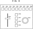
- Fig. 9 is a view showing an example of a window as the controller for operating the slow camera assist rate or the scene playback speed according to this embodiment.
- a slider 1014 is assumed to be used to set the slow camera assist rate or the scene playback speed.
- the slider 1014 may be synchronized with the slow camera assist rate control bar 702 or the scene playback speed control bar 703. Further, a value may be set in advance in each of buttons 1001 to 1013. By pressing the button, the value of the slow camera assist rate or the scene playback speed may be replaced by the set value, and the set value may be reflected by pressing a determination button 1014.
- the setting method using the controller is not limited to this.
- the operator of the virtual camera can easily change the parameter related to the playback speed of the virtual viewpoint image or the parameter related to the moving speed of the virtual camera.
- the present invention is applicable to not only when creating a camera path but also when operating a virtual camera.
- the moving speed of the virtual camera the moving amount of the virtual camera according to the user operation
- it may be configured such that each of the playback speed of the virtual viewpoint image and the moving speed of the virtual camera can be freely set by the operator, or the moving speed of the virtual camera is automatically determined in accordance with the playback speed of the virtual viewpoint image.
- the speed of change of the virtual viewpoint controlled in accordance with the playback speed of the virtual viewpoint image is not limited to the moving speed of the virtual camera (the speed of change of the position), and it may be the speed of change of the orientation or angle of view of the virtual camera. Further, the speed of change of the virtual viewpoint may be determined based on the playback speed of the virtual viewpoint and the input according to the user operation. For example, if the user greatly tilts the joystick of the controller, the speed of change of the virtual viewpoint may be increased, and if the user slightly tilts the joystick, the speed of change of the virtual viewpoint may be decreased. As the playback speed of the virtual viewpoint image is increased, the sensitivity of change of the virtual viewpoint according to the user operation may be increased. Further, as the playback speed of the virtual viewpoint image is increased, the upper limit of the speed of change of the virtual viewpoint when the joystick is tilted to the maximum may be increased.
- the playback speed of the virtual viewpoint image in the camera path creation mode may be controlled in accordance with the speed of change of the virtual viewpoint in accordance with the user operation.
- the virtual viewpoint image may be played back at the normal speed (1x speed)
- the virtual viewpoint image may be played back at a speed (for example, 0.5x speed) lower than the normal speed.
- the present invention can be implemented by processing of supplying a program for implementing one or more functions of the above-described embodiments to a system or apparatus via a network or storage medium, and causing one or more processors in the computer of the system or apparatus to read out and execute the program.
- the present invention can also be implemented by a circuit (for example, an ASIC) for implementing one or more functions.
Landscapes
- Engineering & Computer Science (AREA)
- Multimedia (AREA)
- Signal Processing (AREA)
- Databases & Information Systems (AREA)
- Human Computer Interaction (AREA)
- Computer Security & Cryptography (AREA)
- Processing Or Creating Images (AREA)
- Two-Way Televisions, Distribution Of Moving Picture Or The Like (AREA)
- Studio Devices (AREA)
- Television Signal Processing For Recording (AREA)
Abstract
Description
- The present invention relates to an information processing apparatus, an information processing method, and a program.
- In recent years, a technique of performing multi-viewpoint synchronous image capturing by installing a plurality of cameras in different positions and using a plurality of viewpoint images obtained by the image capturing operation to generate not only images from the camera installation positions but also a virtual viewpoint image formed from one or more arbitrary viewpoints is gaining attention.
- A service using a virtual viewpoint image allows a video producer to produce an impactful viewpoint content from, for example, a video obtained by capturing a soccer game or a basketball game. In addition, it also allows a user who is the viewer of the content to watch the game by freely moving his/her viewpoint, and provides the user with a more true-to-life viewing experience compared to conventional captured images.
-
PTL 1 discloses a control method of a virtual camera for implementing a composition desired by the operator of the virtual camera. More specifically, an arrangement is disclosed in which, during playback of video content data including arbitrary viewpoint video data, if the user performs an operation to move the viewpoint of the arbitrary viewpoint video data, the viewpoint movement amount is controlled for each area in the arbitrary viewpoint video being played back. - PTL 1: Japanese Patent Laid-Open No.
2012-109719 - However, the technique described in
PTL 1 has a problem that it is difficult to generate a virtual viewpoint image with a composition desired by the operator in accordance with movement of an object. - The present invention has been made in consideration of the above-described problem, and has as its object to provide a technique for facilitating generation of a virtual viewpoint image with a composition desired by the operator of the virtual viewpoint.
- An information processing apparatus according to the present invention which achieves the above-described object is characterized by comprising determination means for determining a playback speed of a virtual viewpoint image based on a plurality of captured images, acceptance means for accepting an input according to a user operation during playback of the virtual viewpoint image at the playback speed determined by the determination means, and control means for performing control to change a virtual viewpoint corresponding to the virtual viewpoint image based on the input accepted by the acceptance means, and performing control such that a speed of change of the virtual viewpoint which is changed in accordance with acceptance of an input according to a specific user operation during playback of the virtual viewpoint image at a first playback speed becomes lower than a speed of change of the virtual viewpoint which is changed in accordance with acceptance of an input according to the specific user operation during playback of the virtual viewpoint image at a second playback speed higher than the first playback speed.
- According to the present invention, it is facilitated to generate a virtual viewpoint image with a composition desired by the operator of the virtual viewpoint.
- Other features and advantages of the present invention will be apparent from the following description taken in conjunction with the accompanying drawings. Note that the same reference numerals denote the same or like components throughout the accompanying drawings.
- The accompanying drawings, which are incorporated in and constitute a part of the specification, illustrate embodiments of the invention and, together with the description, serve to explain principles of the invention.
-
Fig. 1A is a block diagram showing an example of the overall configuration of an image processing system according to the first embodiment; -
Fig. 1B is a block diagram showing an example of the hardware arrangement of an information processing apparatus; -
Fig. 2 is a block diagram showing an example of the arrangement of the information processing apparatus according to the first embodiment; -
Fig. 3 is a view showing an example of the concept of time according to the first embodiment; -
Fig. 4 is a flowchart illustrating an example of the processing of a recording time calculation unit according to the first embodiment; -
Fig. 5A is a flowchart illustrating an example of the processing of the information processing apparatus according to the first embodiment; -
Fig. 5B is a flowchart illustrating an example of the processing of the information processing apparatus according to the first embodiment; -
Fig. 6 is a block diagram showing an example of the arrangement of an information processing apparatus according to the second embodiment; -
Fig. 7 is a table showing an example of camera parameters transmitted by a communication unit to a virtual viewpoint image generating server or a recording/editing apparatus according to the second embodiment; -
Fig. 8 is a view showing an example of a UI for generating a replay virtual viewpoint image according to the third embodiment; and -
Fig. 9 is a view showing an example of a controller according to the third embodiment. - Embodiments will be described below with reference to accompanying drawings. Note that the arrangements shown in the embodiments to be described below are merely examples, and the present invention is not limited to the illustrated arrangements.
- In the first embodiment, an example will be described in which the playback speed of a virtual viewpoint image is changed between when a camera path of a virtual camera is created and when the camera path is reproduced. More specifically, when creating a camera path, the camera path is created by operating and moving a virtual camera corresponding to a virtual viewpoint while playing back a virtual viewpoint image for twice the actual time (at the 0.5x speed). By the operator designating the playback speed suited for creating the camera path, it becomes possible to precisely move the virtual camera, and this makes it easy to follow an object included in the virtual viewpoint image. Further, the operator can also designate the playback speed at the time of reproducing the camera path. For example, the virtual viewpoint image is played back for the actual time (twice the 0.5x speed at the time of creating the camera path). This makes it possible to play back the comfortable virtual viewpoint image. The camera path is an example of viewpoint information indicating a temporal change of the virtual viewpoint corresponding to the virtual viewpoint image.
-
Fig. 1A is a block diagram showing the overall configuration of animage processing system 10 according to this embodiment. Theimage processing system 10 includes an image capturingsystem 101, a virtual viewpointimage generating server 102, and aninformation processing apparatus 103. Theimage processing system 10 can generate a virtual viewpoint image. - The image capturing
system 101 includes a plurality of cameras installed in different positions, and synchronously captures a plurality of images from multiple viewpoints. Then, the plurality of images synchronously captured from the multiple viewpoints are transmitted to the virtual viewpointimage generating server 102. - The virtual viewpoint
image generating server 102 generates, based on the plurality of images synchronously captured from the multiple viewpoints, a virtual viewpoint image observed from a virtual camera, which is a virtual camera corresponding to a virtual viewpoint movable in the image capturing space. That is, the virtual viewpointimage generating server 102 can generate a virtual viewpoint image that also includes an image observed from a viewpoint different from that of any camera included in the image capturingsystem 101. The viewpoint of the virtual camera is expressed by camera parameters determined by theinformation processing apparatus 103 to be described later. - The virtual viewpoint
image generating server 102 sequentially generates a virtual viewpoint image from the plurality of received images. That is, the virtual viewpointimage generating server 102 can generate a live virtual viewpoint image. Note that the live virtual viewpoint image that can be generated by theimage processing system 10 is a virtual viewpoint image based on a plurality of images captured by the image capturingsystem 101 at the time determined in consideration of the processing delay in the image capturingsystem 101 and the virtual viewpointimage generating server 102 with respect to the current time. - Further, the virtual viewpoint
image generating server 102 includes a database, and has a function of recording the plurality of received images. Hence, the virtual viewpointimage generating server 102 can generate a replay virtual viewpoint image. A replay virtual viewpoint image is a virtual viewpoint image based on images captured by the image capturingsystem 101 at an arbitrary time, for example, a virtual viewpoint image that is played back when the created camera path is reproduced. Note that unless otherwise stated, the word "image" used in the description includes both the concept of a moving image and the concept of a still image. That is, theimage processing system 10 can process both a still image and a moving image. - The
information processing apparatus 103 controls the virtual camera and determines camera parameters representing the viewpoint of the virtual camera. The camera parameters of the virtual camera include at least parameters for designating the position, posture, and time of the virtual camera. The camera parameters of the virtual camera may further include the zoom. The time of the camera parameter is the time between the play disclosure time and the play end time to be described later with reference toFig. 3 . This time may be expressed in a format such as 20xx year x month x day x hour x minute x second, or may be expressed as the time obtained when the play start time is used as the reference (zero). - The position of the virtual camera designated by the camera parameters may be a position indicating a set of three-dimensional coordinates. In addition, a position designated by the camera parameters of the virtual camera may be indicated by the respective coordinates of X-, Y-, and Z- axes of a three-axis Cartesian coordinate system. In this case, a position designated by the camera parameters of the virtual camera is a position indicating the set of coordinates and may be formed from parameters of three axes, that is, the X-axis, the Y-axis, and the Z-axis. Note that an arbitrary position in the image capturing space may be set as the origin.
- The posture of the virtual camera designated by the camera parameters can be indicated by an angle formed by three axes of pan, tilt, and roll. In this case, the posture of the virtual camera designated by camera parameters may be formed from parameters of three axes which are pan, tilt, and roll. The zoom of the virtual camera designated by the camera parameters is indicated by, for example, the focal distance as one axis, and the zoom and the time each are defined as a parameter of one axis.
- Hence, the camera parameters of the virtual camera can include at least parameters of eight axes. The
information processing apparatus 103 can control these eight axes. Note that the camera parameters may include parameters defining other elements and may not include all of the above-described parameters of eight axes. - The
information processing apparatus 103 transmits the determined camera parameters of the virtual camera to the virtual viewpointimage generating server 102. Next, the virtual viewpointimage generating server 102 generates a virtual viewpoint image based on the received camera parameters and transmits the generated virtual viewpoint image to theinformation processing apparatus 103. Note that it may be arranged so that a live virtual viewpoint image and a replay virtual viewpoint image will be generated by oneinformation processing apparatus 103 in the manner of this embodiment or it may be arranged so that the live virtual viewpoint image and the replay virtual viewpoint image will be generated in different apparatuses by preparing two information processing apparatuses. - Note that the configuration of the
image processing system 10 is not limited to that shown inFig. 2 . For example, theinformation processing apparatus 103 may include the virtual viewpointimage generating server 102. -
Fig. 1B is a block diagram showing an example of the hardware arrangement of theinformation processing apparatus 103 according to this embodiment. Theinformation processing apparatus 103 includes aCPU 111, aRAM 112, aROM 113, acommunication unit 114, and an input/output unit 115. - The
CPU 111 controls the overall operation of theinformation processing apparatus 103 by reading out and executing computer programs and data stored in theRAM 112 and theROM 113. TheRAM 112 temporarily stores the computer program read out from theROM 113, intermediate results of a calculation or the like, data supplied from the outside via thecommunication unit 114, and the like. Note that theROM 113 holds the computer programs and data that need not be changed. Note that theRAM 112 and theROM 113 are collectively referred to as memories. - The
communication unit 114 includes a communication unit of an Ethernet®, a USB, or the like, and communicates with the virtual viewpointimage generating server 102. The input/output unit 115 includes a plurality of controllers for controlling the virtual camera and a plurality of display units for outputting and displaying the state of the virtual camera and the like. The controllers are, for example, operation units such as a joystick, a jog dial, a touch panel, a keyboard, and a mouse, and each controller can accept an input according to a user operation of the operator. For example, by operating the joystick, the operator can freely move the position of the virtual camera in space or freely change the orientation and angle of view of the virtual camera in the virtual viewpoint image which is played back when creating the camera path. More specifically, the operator can create the camera path by moving the virtual camera so as to follow the side of a specific player on the court while observing the virtual viewpoint image played back when creating the camera path. -
Fig. 2 is a block diagram showing an example of the functional arrangement of theinformation processing apparatus 103 which forms theimage processing system 10 according to this embodiment. Theinformation processing apparatus 103 includes thecommunication unit 114, the input/output unit 115, a recordingtime calculation unit 116, a position/posture obtaining unit 117, and a camerapath storage unit 118. Theinformation processing apparatus 103 is connected to the virtual viewpointimage generating server 102. - The
communication unit 114 sequentially outputs, to the virtual viewpointimage generating server 102 or the input/output unit 115, camera parameters input from the position/posture obtaining unit 117 or the camerapath storage unit 118 using the communication unit of an Ethernet, a USB, or the like. Further, thecommunication unit 114 may sequentially outputs, to the input/output unit 115, a virtual viewpoint image input from the virtual viewpointimage generating server 102 using the communication unit of an Ethernet, a USB, or the like. - The input/
output unit 115 outputs, to the recordingtime calculation unit 116, camera parameters or the mode of the virtual viewpoint image, which are input by the operator using the controller. Further, the input/output unit 115 outputs, to the position/posture obtaining unit 117, the initial position, initial posture, or movement instruction amount of the virtual camera. The movement instruction amount is, for example, the distance in the tilt direction corresponding to the operation amount (tilt amount) of the joystick as the controller. Alternatively, the movement instruction amount may be the amount corresponding to the number of times the joystick is tilted. In this case, it may be determined in advance that a predetermined distance is moved by one tilt. Alternatively, if the movement amounts in the x, y, and z directions with respect to the current position are input from the controller, those values may be used. The operator of the virtual camera can designate the camera parameter of the virtual camera or the movement instruction amount of the virtual camera by operating the controller. The details of the mode of the virtual viewpoint image will be described later. - Further, the input/
output unit 115 outputs, to the recordingtime calculation unit 116, the play start time and the play end time of a replay virtual viewpoint image based on the image capturing time (play time hereinafter) by theimage capturing system 101, which are input by the operator using the controller. Each of the play start time and the play end time is determined by, for example, the video producer indicating, to the operator of the virtual camera, the actual time to be used for playback of the video obtained by capturing a game of soccer or the like, and the operator inputting the actual time to the input/output unit 115 using the controller. Note that the video producer and the operator of the virtual camera are not necessarily different persons, and the video producer and the operator of the virtual camera may be the same person. Further, the method of determining the play start time and the play end time is not limited to this example, and they may be determined by theimage processing system 10 automatically extracting the actual start time and the actual end time of a characteristic scene such as a goal scene. - Further, the input/
output unit 115 outputs, to the recordingtime calculation unit 116, the information of the playback speed of the virtual viewpoint image at the time of creating the camera path and/or the information of the playback speed of the virtual viewpoint image at the time of reproducing the camera path, which are input by the operator using the controller. Furthermore, the input/output unit 115 outputs, to the position/posture obtaining unit 117, the moving speed of the virtual camera input by the operator using the controller. The playback speed of the virtual viewpoint image at the time of creating the camera path is assumed to be determined by the ratio based on the speed of the actual time, but the concept of the playback speed is not limited to this. In addition, the playback speed of the virtual viewpoint image at the time of reproducing the camera path is assumed to be determined by the ratio based on the frame rate (for example, 60 fps) for registering the camera parameters at the time of creating the camera path, but the present invention is not limited to this. Further, the moving speed of the virtual camera is assumed to be determined by the ratio based on the human running speed (for example, 10 m/s), but the concept of the moving speed is not limited to this. Note that the playback speed of the virtual viewpoint image is not limited to be determined based on the designation operation by the user, and it may be automatically determined. For example, the playback speed of the virtual viewpoint image may be determined based on movement of an object included in at least any of the plurality of captured images obtained by theimage capturing system 201. - In addition, the input/
output unit 115 includes the display unit such as the plurality of displays, and displays the virtual viewpoint image, the camera parameters, and the state of the virtual camera, which have been input from thecommunication unit 114. This enables the operator to operate the virtual camera using the controller while observing the virtual viewpoint image displayed on the display unit. However, the present invention is not limited to this, and the operator who operates the display unit and the operator who operates the controller may not be the same person. - The
information processing apparatus 103 includes at least two modes for controlling the playback speed of the virtual viewpoint image. One is a camera path creation mode, and the other is a camera path reproduction mode. It may be configured such that, for example, a switching button is provided on a user interface (UI) as the input/output unit 115 and the mode can be switched in accordance of pressing of the button. - The camera path creation mode is a mode in which the virtual camera is moved in the image capturing space based on the operation of the operator while the virtual viewpoint image (video) being played back is observed from the virtual viewpoint at which the virtual camera is located, and the movement locus of the virtual camera is stored as a camera path. In other words, the camera path creation mode is a mode in which the virtual viewpoint corresponding to the virtual viewpoint image being played back is changed in accordance with the user operation during playback of the virtual viewpoint image, and the viewpoint information indicating the change of the virtual viewpoint in accordance with the user operation is stored.
- In the camera path creation mode, the recording
time calculation unit 116 determines, based on the camera parameters, the play start time, the play end time, and the playback speed of the virtual viewpoint image at the time of creating the camera path, which have been input from the input/output unit 115, the actual time of the virtual viewpoint image to be generated. Then, the time included in the camera parameter is updated. Further, the recordingtime calculation unit 116 adds, to the camera parameter, the actual time at which the camera path information is recorded (camera parameter recording time), and outputs the camera parameter to the position/posture obtaining unit 117. Here, the time of the camera parameter and the camera parameter recording time are different pieces of information. - The time of the virtual viewpoint image to be generated is started from the play start time. When the time of the virtual viewpoint image to be generated is updated, the time is determined based on the time of the previously generated virtual viewpoint image and the playback speed of the virtual viewpoint image. It is assumed that the time of the virtual viewpoint image to be generated shall not exceed the play end time. Note that the method of determining the time is not limited to this. Further, the first camera parameter recording time (camera path recording start time) and the last camera parameter recording time (camera path recording end time) are stored in the memory.
- The camera path reproduction mode is a mode in which the virtual viewpoint image (video) along the created camera path is generated. In the camera path reproduction mode, the recording
time calculation unit 116 calculates, based on the playback speed of the virtual viewpoint image at the time of reproducing the camera path, which has been input from the input/output unit 115, the camera parameter recording time of the virtual viewpoint image to be generated. Then, the recordingtime calculation unit 116 outputs the calculated camera parameter recording time to the camerapath storage unit 118. In the method of calculating the camera parameter recording time, for example, the time is started from the camera path recording start time stored in the memory and, if the camera path playback speed is the 1x speed, the time is advanced at the same speed as when recording the camera path, and if the camera path playback speed is the 2x speed, the time is advanced at twice the speed in recording the camera path. Note that the method of calculating the camera parameter recording time is not limited to this. - The position/
posture obtaining unit 117 calculates and obtains, based on the movement instruction amount and the moving speed, initial position, and initial posture of the virtual camera, which have been input from the input/output unit 115, and the camera parameters input from the recordingtime calculation unit 116, the position and posture of the virtual camera of the virtual viewpoint image to be generated. Then, the position/posture obtaining unit 117 updates the position and posture of the camera parameters, and outputs the information of the updated camera parameters to thecommunication unit 114 and the camerapath storage unit 118. The position and posture of the virtual camera are started from the initial position and the initial posture, respectively. When updating the position and the posture, they are assumed to be determined based on the position and posture of the camera parameters of the previously generated virtual viewpoint image, the movement instruction amount, and the moving speed of the virtual camera. Note that the method of determining the position and posture of the virtual camera is not limited to this. - The camera
path storage unit 118 sequentially stores the camera parameters of the virtual camera input from the position/posture obtaining unit 117. Further, the camerapath storage unit 118 obtains, based on the camera parameter recording time input from recordingtime calculation unit 116, the camera parameters at this recording time from the camera parameters stored in the memory, and outputs them to thecommunication unit 114. - Here,
Fig. 3 is an image view of the time axis according to the first embodiment in a case in which the virtual viewpoint image is played back at the 0.5x playback speed when creating the camera path and the virtual viewpoint image is played back at two speeds (the normal speed (1x speed) and the 2x speed) when reproducing the camera path. - For example, the play time (actual time) of a sport is defined as the time from the play start time to the play end time. For example, this assumes a highlight scene of soccer or the like. Since the playback speed of the virtual viewpoint image at the time of creating the camera path is the 0.5 speed, its playback time becomes twice the play time. The camera path recording time is the actual time, and the same length as the playback time of the virtual viewpoint image at the time of creating the camera path. That is, the camera path recording time is twice the play time.
- In a case of the normal speed (1x speed), the playback time of the virtual viewpoint image at the time of reproducing the camera path is the same length as the playback time of the virtual viewpoint image and the camera path recording time at the time of creating the camera path. That is, the playback time of the virtual viewpoint image at the time of reproducing the camera path is twice the play time. In a case of the 2x speed, the playback time of the virtual viewpoint image at the time of reproducing the camera path is the same length as the play time.
- That is, if the playback speed of the virtual viewpoint image at the time of reproducing the camera path is the normal speed (1x speed), the playback speed of the replay virtual viewpoint image is made to be twice the play time. If the playback speed of the virtual viewpoint image at the time of reproducing the camera path is the 2x speed, the playback time of the replay virtual viewpoint image is made to be the same length as the play time.
- With this arrangement, in a case in which the object moves fast, the operator can create the camera path while decreasing the playback speed of the virtual viewpoint image in the camera path creation mode (for example, at the 0.5x speed) to facilitate following the object. To the contrary, in a case in which the object moves too slowly (for example, observing a slowly moving animal, observing the emergence of an insect, or the like), the operator can create the camera path while increasing the playback speed of the virtual viewpoint image in the camera path creation mode to facilitate following the object.
- Conventionally, the camera path can be reproduced only for the time equal to the camera path recording time. However, according to this embodiment, it becomes possible to reproduce the created camera path for the play time (or an arbitrary time). That is, in the camera path reproduction mode in which a virtual viewpoint image generated based on a created camera path and a plurality of captured images is played back, by setting the playback speed different from the playback speed in the camera path creation mode (for example, twice the playback speed in the camera path creation mode), the virtual viewpoint image can be played back at the playback speed suitable for viewing.
-
Fig. 4 is a flowchart illustrating the procedure of switching processing between the camera path creation mode at the time of creating a camera path and the mode at the time of reproducing the camera path, which is performed by the recordingtime calculation unit 116 of theinformation processing apparatus 103 according to the first embodiment. - In step S401, the recording
time calculation unit 116 obtains, from the input/output unit 115, the mode of playback speed of the virtual viewpoint image and various kinds of parameters. In step S402, the recordingtime calculation unit 116 determines the kind of the mode obtained in step S401. If the mode is the camera path creation mode, the process advances to step S403. On the other hand, if the mode is the camera path reproduction mode, the process advances to step S404. In step S403, the recordingtime calculation unit 116 calculates the play time, and updates the camera parameters. Then, the camera parameters are output to the position/posture obtaining unit 117. In step S404, the recordingtime calculation unit 116 calculates the camera parameter recording time for generating the virtual viewpoint image, and outputs it to the camerapath storage unit 118. Thus, a series of processing illustrated inFig. 4 is terminated. - Next,
Fig. 5A is a flowchart illustrating the procedure of the processing at the time of creating a camera path performed by the information processing apparatus according to the first embodiment. - In step S501, the input/
output unit 115 obtains, as initial parameters, the camera parameters (position, posture, and time), the initial position and initial posture of the virtual camera, and the start time and end time of a replay virtual viewpoint image. In step S502, the input/output unit 115 obtains, as parameters, the movement instruction amount of the virtual camera, the playback speed of the virtual viewpoint image at the time of creating the camera path, and the moving speed of the virtual camera. In step S503, the input/output unit 115 checks the obtained data. If the input/output unit 115 can check the obtained data, the process advances to step S504. If the input/output unit 115 cannot check the obtained data, the process is terminated. - In step S504, the recording
time calculation unit 116 determines, based on the camera parameters, the start time and the end time, and the playback speed of the virtual viewpoint image, all of which are obtained by the recordingtime calculation unit 116, the play time of the virtual viewpoint image to be generated, and updates the time of the camera parameter. Note that the time is started from the play start time, and shall not exceed the play end time. - In step S505, the position/
posture obtaining unit 117 calculates, based on the movement instruction amount, the moving speed, initial position, and initial posture of the virtual camera, and the camera parameters, all of which are obtained by the position/posture obtaining unit 117, the position and posture of the virtual camera of the virtual viewpoint image to be generated, and updates the position and posture of the camera parameters. The position and posture of the virtual camera are started from the initial position and the initial posture, respectively. When updating the position and the posture, they are determined based on the position and posture of the previous camera parameters, the movement instruction amount, and the moving speed of the virtual camera. - In step S506, the camera
path storage unit 118 records the determined camera parameters in the memory. In step S507, thecommunication unit 114 transmits, to the virtual viewpointimage generating server 102, the camera parameters at the viewpoint of the virtual camera at the updated movement destination, and instructs to generate the virtual viewpoint image. Based on the information of the time included in the camera parameters, the virtual viewpointimage generating server 102 determines the time of the virtual viewpoint image to be generated, and generates the virtual viewpoint image at the position and posture of the virtual camera at the determined time. - In step S508, the
communication unit 114 receives, from the virtual viewpointimage generating server 102, the virtual viewpoint image generated by the virtual viewpointimage generating server 102. - In step S509, the input/
output unit 115 displays the received virtual viewpoint image on the display unit such as the display. Then, the process returns to step S502. The operator of the virtual camera can operate and move the virtual camera using the controller of the input/output unit 115 in step S502 while observing the virtual viewpoint image. The movement locus of the virtual camera is created as the camera path. Further, if needed, the operator can adjust the playback speed of the virtual viewpoint image or the moving speed of the virtual camera in step S502 using the controller of the input/output unit 115. Note that in the example shown inFig. 3 , the camera path is generated at the constant playback speed, so that a series of processing is repeated without changing the playback speed from the fixed value. Thus, the series of processing illustrated inFig. 5A is terminated. - Next,
Fig. 5B is a flowchart illustrating the procedure of the processing at the time of reproducing the camera path performed by the information processing apparatus according to the first embodiment. - In step S510, the input/
output unit 115 obtains, as a parameter, the information of the playback speed of the virtual viewpoint image at the time of reproducing the camera path. In step S511, the recordingtime calculation unit 116 calculates, based on the obtained information of the playback speed of the virtual viewpoint image, the camera parameter recording time. The camera parameter recording time is started from the camera path recording start time. - In step S512, the camera
path storage unit 118 obtains, from the camera path recorded in the memory in step S506, the camera parameters corresponding to the camera parameter recording time calculated in step S511. In step S513, the camerapath storage unit 118 checks the data obtained in step S512. If the camerapath storage unit 118 can check the obtained data, the process advances to step S514. On the other hand, if the camerapath storage unit 118 cannot check the obtained data, the process is terminated. - In step S514, the
communication unit 114 transmits the obtained camera parameters to the virtual viewpointimage generating server 102, and instructs to generate the virtual viewpoint image. Based on the information of the time included in the camera parameters, the virtual viewpointimage generating server 102 determines the time of the virtual viewpoint image to be generated, and generates the virtual viewpoint image at the position and posture of the virtual camera at the determined time. In step S515, thecommunication unit 114 receives, from the virtual viewpointimage generating server 102, the virtual viewpoint image generated by the virtual viewpointimage generating server 102. - In step S516, the input/
output unit 115 displays the received virtual viewpoint image on the display unit such as the display. Then, the process returns to step S510. The operator of the virtual camera can adjust the playback speed of the virtual viewpoint image at the time of reproducing the camera path using the controller of the input/output unit 115 in step S510 while observing the virtual viewpoint image. This enables play back of the virtual viewpoint image at a low playback speed in a highlight scene which is regarded as important by the operator, and play back the virtual viewpoint image at a high playback speed in a scene which is not regarded as important. Note that in the example shown inFig. 3 , the camera path is reproduced at the constant playback speed, so that a series of processing is repeated without changing the playback speed from the fixed value. Thus, the series of processing illustrated inFig. 5B is terminated. - As has been described above, in this embodiment, processing is performed in which the information of the playback speed of a virtual viewpoint image in the camera path creation mode for creating a camera path that represents the movement locus of a virtual camera capable of freely moving the image capturing space while playing back the virtual viewpoint image is obtained, and an operation is accepted for creating the camera path by moving the virtual camera in the virtual viewpoint image from the viewpoint of the virtual camera currently being played back at the obtained playback speed.
- With this processing, it is possible to adjust, at the time of creating the camera path, the playback speed of the virtual viewpoint image to a suitable speed according to the speed of the object. For example, in a case in which the object moves fast, by decreasing the playback speed of the virtual viewpoint image and operating the virtual camera, the operator can easily follow the movement of the object, and easily create the camera path. To the contrary, in a case in which the object moves too slowly (for example, observing a slowly moving animal, observing the emergence of an insect, or the like), the operator can create the camera path while increasing the playback speed of the virtual viewpoint image to facilitate following the object.
- Further, it is configured such that, in addition to the playback speed of the virtual viewpoint image at the time of creating the camera path, the playback speed of the virtual viewpoint image at the time of reproducing the camera path can also be adjusted to a preferable speed of the operator. Thus, it also becomes possible to reproduce the created camera path for the actual time (or an arbitrary time).
- That is, it becomes easy to create a camera path at the time of creating the camera path, and a virtual viewpoint image based on the actual time and without discomfort can be provided at the time of reproducing the camera path.
- In the second embodiment, an example will be described in which the information processing apparatus transmits some or all of camera parameters (the position, posture, time, and the like of a virtual camera) of a virtual viewpoint image to an external apparatus, and the external apparatus records and edits a replay virtual viewpoint image.
-
Fig. 6 is a block diagram showing a configuration example of an image processing system that generates a replay virtual viewpoint image using the external apparatus according to this embodiment. Animage processing system 20 includes animage capturing system 201, a virtual viewpointimage generating server 202, and aninformation processing apparatus 203, and can communicate with a recording/editing apparatus 204 as the external apparatus. Theinformation processing apparatus 203 includes acommunication unit 214, an input/output unit 215, a recordingtime calculation unit 216, a position/posture obtaining unit 217, and a camerapath storage unit 218. - The
image capturing system 201 is similar to theimage capturing system 101 shown inFig. 2 . The virtual viewpointimage generating server 202 may add, to a virtual viewpoint image, information of all or some of camera parameters input from thecommunication unit 214, and output the virtual viewpoint image to the recording/editing apparatus 204. The method of adding the information to the virtual viewpoint image is assumed to be performed by, for example, describing the information in the ancillary area of an SDI (Serial Digital Interface) signal, but the method is not limited to this. - The
communication unit 214 has, in addition to the function of thecommunication unit 114 shown inFig. 2 , a function of sequentially transmitting, to the recording/editing apparatus 204, all or some of the camera parameters input from the position/posture obtaining unit 217 or the camerapath storage unit 218 using a communication means of an Ethernet, an USB, or the like. - The input/
output unit 215 is similar to the input/output unit 115 shown inFig. 2 . The recordingtime calculation unit 216 has, in addition to the function of the recordingtime calculation unit 116 shown inFig. 2 , a function of adding the playback speed of the virtual viewpoint image to the camera parameter. The position/posture obtaining unit 217 has, in addition to the function of the position/posture obtaining unit 117 shown inFig. 2 , a function of adding the moving speed of the virtual camera to the camera parameter. The camerapath storage unit 218 is similar to the camerapath storage unit 118 shown inFig. 2 . - The recording/
editing apparatus 204 records the virtual viewpoint image input from the virtual viewpointimage generating server 202 or thecommunication unit 214. Further, the recording/editing apparatus 204 edits the virtual viewpoint image using the virtual viewpoint image input from the virtual viewpointimage generating server 102 or thecommunication unit 114 and all or some of the camera parameters input from thecommunication unit 114. Note that the pieces of information obtained here are the camera parameters, the information of the playback speed of the virtual viewpoint image, and the information of the moving speed of the virtual camera. - An example of the method of editing a virtual viewpoint image is a method in which the operator or the system refers to the information including the camera parameters (position, posture, time, and the like) of a virtual camera, the playback speed of the virtual viewpoint image, and the moving speed, and the virtual viewpoint image is played back at the 2x speed if the playback speed of the virtual viewpoint image is the 0.5x speed. This enables creation of a replay virtual viewpoint image played back for the actual time. Note that the method of editing a virtual viewpoint image is not limited to this.
-
Fig. 7 shows an example of camera parameters to be output by thecommunication unit 114 to the virtual viewpointimage generating server 102 or the recording/editing apparatus 204. However, the method of describing the camera parameters to be output is not limited to this. In the example shown inFig. 7 , the time is 01:02:03:00, the playback mode of the virtual viewpoint image is the camera path creation mode, the playback speed of the virtual viewpoint image is 0.5, the moving speed of the virtual camera is 0.5, the x position of the virtual camera is 100, and the y position thereof is 200. Note that the parameters to be output from thecommunication unit 114 to the virtual viewpointimage generating server 102 or the recording/editing apparatus 204 are not limited to them. For example, information indicating the playback speed different from the playback speed in the camera path creation mode, which is information indicating the playback speed in the camera path reproduction mode, may be included in the parameters to be output. - With the processing as described above, it becomes possible that the information processing apparatus transmits, to an external apparatus (for example, the recording/editing apparatus), some or all of the camera parameters of a virtual viewpoint image, and the external apparatus records/edits a replay virtual viewpoint image.
- According to this embodiment, a virtual viewpoint image and meta information thereof are sequentially output to the recording/editing apparatus in accordance with creation of a camera path. This enables faster recording and editing, so that faster video distribution becomes possible. Further, a third party existing outside the image processing system can use the recording/editing apparatus to perform recording/editing.
- In the third embodiment, an example will be described in which the operator of a virtual camera changes a parameter related to the playback speed of a virtual viewpoint image or a parameter related to the moving speed of a virtual camera.
-
Fig. 8 is an image view of a user interface (UI) used by the operator to change a parameter related to the playback speed of a virtual viewpoint image and a parameter related to the moving speed of a virtual camera according to this embodiment. The UI includes ascene playback speed 303, a virtualcamera moving speed 404, a slow camera assistrate control bar 702, and a scene playbackspeed control bar 703. - The operator operates the slow camera assist
rate control bar 702 as the parameter related to the moving speed of the virtual camera. Further, the operator operates the scene playbackspeed control bar 703 as the parameter related to the playback speed of the virtual viewpoint image. The slow camera assistrate control bar 702 and the scene playbackspeed control bar 703 operate independently. However, the operations of the slow camera assistrate control bar 702 and the scene playbackspeed control bar 703 are not limited to this. For example, it may be configured such that, if the operator operates the scene playbackspeed control bar 703 to change the playback speed of the virtual viewpoint image, the moving speed of the virtual camera suitable for the changed playback speed may be automatically calculated and reflected on the slow camera assistrate control bar 702, thereby causing the slow camera assistrate control bar 702 to synchronously operate. - The UI may be displayed on a display unit such as a display included in an input/
output unit 115. The UI may be operated using an input unit such as a controller included in the input/output unit 115. - In
Fig. 8 , thescene playback speed 303 is the playback speed of the virtual viewpoint image input and displayed by the input/output unit 115, and this speed is output to a recordingtime calculation unit 116. "100%" means the normal playback speed. If thescene playback speed 303 is lower than 100%, slow playback is performed. For example, if a video of one sec for the actual time is played back for two sec, thescene playback speed 303 is 50%. If thescene playback speed 303 is higher than 100%, fast-forward playback is performed. If thescene playback speed 303 is 0%, the virtual visual image displayed on the input/output unit 115 is stopped. Note that even if thescene playback speed 303 is 0%, it is possible to control the virtual camera. For example, it is possible to generate a virtual viewpoint image that captures the whole circumference of the player at the moment the player kicks the ball. - The slow camera assist
rate 404 is the ratio of decreasing the moving speed of the camera input and displayed by the input/output unit 115 when a slow camera assist function is enabled, and is output to a position/posture obtaining unit 117. At this time, the moving speed of the virtual camera is automatically determined in accordance with the playback speed of the virtual viewpoint image in the camera path creation mode. That is, it is configured such that the moving speed of the virtual camera is automatically changed in accordance with the change of the scene playback speed (the playback speed of the virtual viewpoint image). - For example, if the scene playback speed is changed to 50%, the moving speed of the virtual camera according to the user operation during playback of the virtual viewpoint image at the changed playback speed may be decreased to 50% of the normal moving speed. Further, for example, if the scene playback speed is changed to 25%, the moving speed of the virtual camera may be decreased to 25% of the normal moving speed. The slow camera assist decreases both the scene playback speed and the moving speed of the virtual camera, and this facilitates the operation for recording a replay clip. For example, this facilitates the operation of the virtual camera when creating a replay clip for following a fast-moving ball. Note that if the scene playback speed is set to 100% or higher to perform fast forward, the moving speed of the virtual camera may also be set to be equal to or higher than the normal speed.
- The slow camera assist
rate control bar 702 controls the moving speed of the virtual camera to be input and displayed by the input/output unit 115 during execution of the slow camera assist, and is output to the position/posture obtaining unit 117. The scene playbackspeed control bar 703 controls the scene playback speed input and displayed by the input/output unit 115, and is output to the recordingtime calculation unit 116. - The function of each of the slow camera assist
rate control bar 702 and the scene playbackspeed control bar 703 may be implemented not only in the form of a bar as shown inFig. 8 , but also in the form of, for example, selection using a pull-down menu or direct input using a text box. Further, the controller included in the input/output unit 115 may be used. Here,Fig. 9 is a view showing an example of a window as the controller for operating the slow camera assist rate or the scene playback speed according to this embodiment. Aslider 1014 is assumed to be used to set the slow camera assist rate or the scene playback speed. - Note that the
slider 1014 may be synchronized with the slow camera assistrate control bar 702 or the scene playbackspeed control bar 703. Further, a value may be set in advance in each ofbuttons 1001 to 1013. By pressing the button, the value of the slow camera assist rate or the scene playback speed may be replaced by the set value, and the set value may be reflected by pressing adetermination button 1014. However, the setting method using the controller is not limited to this. - With the processing as described above, the operator of the virtual camera can easily change the parameter related to the playback speed of the virtual viewpoint image or the parameter related to the moving speed of the virtual camera.
- Note that each of the above-described embodiments has been described while taking the camera path creation mode as an example. However, the present invention is applicable to not only when creating a camera path but also when operating a virtual camera. For example, by changing the moving speed of the virtual camera (the moving amount of the virtual camera according to the user operation) in accordance with the playback speed of the virtual viewpoint image, it becomes easy to operate the virtual camera to follow the movement of the object. Note that it may be configured such that each of the playback speed of the virtual viewpoint image and the moving speed of the virtual camera can be freely set by the operator, or the moving speed of the virtual camera is automatically determined in accordance with the playback speed of the virtual viewpoint image.
- The speed of change of the virtual viewpoint controlled in accordance with the playback speed of the virtual viewpoint image is not limited to the moving speed of the virtual camera (the speed of change of the position), and it may be the speed of change of the orientation or angle of view of the virtual camera. Further, the speed of change of the virtual viewpoint may be determined based on the playback speed of the virtual viewpoint and the input according to the user operation. For example, if the user greatly tilts the joystick of the controller, the speed of change of the virtual viewpoint may be increased, and if the user slightly tilts the joystick, the speed of change of the virtual viewpoint may be decreased. As the playback speed of the virtual viewpoint image is increased, the sensitivity of change of the virtual viewpoint according to the user operation may be increased. Further, as the playback speed of the virtual viewpoint image is increased, the upper limit of the speed of change of the virtual viewpoint when the joystick is tilted to the maximum may be increased.
- Further, the example has been described above in which the playback speed of the virtual viewpoint image is first determined, and the speed of change of the virtual viewpoint is controlled in accordance with the determined playback speed, but the reverse control is also possible. That is, the playback speed of the virtual viewpoint image in the camera path creation mode may be controlled in accordance with the speed of change of the virtual viewpoint in accordance with the user operation. For example, while the user does not move the virtual camera, the virtual viewpoint image may be played back at the normal speed (1x speed), and while the user is moving the virtual viewpoint, the virtual viewpoint image may be played back at a speed (for example, 0.5x speed) lower than the normal speed.
- The present invention can be implemented by processing of supplying a program for implementing one or more functions of the above-described embodiments to a system or apparatus via a network or storage medium, and causing one or more processors in the computer of the system or apparatus to read out and execute the program. The present invention can also be implemented by a circuit (for example, an ASIC) for implementing one or more functions.
- The invention is not limited to the foregoing embodiments, and various variations/changes are possible within the spirit of the invention.
- This application claims priority from Japanese Patent Application No.
2018-132639 filed July 12, 2018
Claims (19)
- An information processing apparatus characterized by comprising:determination means for determining a playback speed of a virtual viewpoint image based on a plurality of captured images;acceptance means for accepting an input according to a user operation during playback of the virtual viewpoint image at the playback speed determined by the determination means; andcontrol means for performing control to change a virtual viewpoint corresponding to the virtual viewpoint image based on the input accepted by the acceptance means, and performing control such that a speed of change of the virtual viewpoint which is changed in accordance with acceptance of an input according to a specific user operation during playback of the virtual viewpoint image at a first playback speed becomes lower than a speed of change of the virtual viewpoint which is changed in accordance with acceptance of an input according to the specific user operation during playback of the virtual viewpoint image at a second playback speed higher than the first playback speed.
- The information processing apparatus according to claim 1, characterized by comprising:viewpoint information generation means for generating viewpoint information indicating a temporal change of the virtual viewpoint according to the control by the control means; andimage generation means for generating, based on the viewpoint information generated by the viewpoint information generation means and the plurality of captured images, a virtual viewpoint image to be played back at a playback speed different from the playback speed determined by the determination means.
- The information processing apparatus according to claim 1, characterized by comprising:viewpoint information generation means for generating viewpoint information indicating a change of the virtual viewpoint according to the control by the control means; andoutput means for outputting, to an image generation apparatus that generates a virtual viewpoint image based on the plurality of captured images, the viewpoint information generated by the viewpoint information generation means.
- The information processing apparatus according to claim 3, characterized in that the output means outputs information indicating a playback speed of the virtual viewpoint image generated by the image generation apparatus.
- The information processing apparatus according to claim 4, characterized in that the playback speed determined by the determination means is different from the playback speed indicated by the information output by the output means.
- The information processing apparatus according to any one of claims 1 to 5, characterized in that the determination means determines the playback speed of the virtual viewpoint image based on a designation operation by a user.
- The information processing apparatus according to any one of claims 1 to 5, characterized in that the determination means determines the playback speed of the virtual viewpoint image based on movement of an object included in at least any of the plurality of captured images.
- The information processing apparatus according to any one of claims 1 to 7, characterized in that the control means determines, based on the playback speed determined by the determination means, an upper limit of the speed of change of the virtual viewpoint.
- The information processing apparatus according to any one of claims 1 to 7, characterized in that the control means determines, based on the playback speed determined by the determination means, a sensitivity of change of the virtual viewpoint according to a user operation.
- The information processing apparatus according to any one of claims 1 to 9, characterized in that the control means changes, based on the input accepted by the acceptance means, at least any of a position, an orientation, and an angle of view of the virtual viewpoint.
- The information processing apparatus according to any one of claims 1 to 10, characterized in that the determination means determines the playback speed of the virtual viewpoint in a camera path creation mode in which a camera path indicating a movement locus of the virtual viewpoint is created during playback of a virtual viewpoint image.
- An information processing apparatus characterized by comprising:determination means for determining a playback speed of a virtual viewpoint image based on a plurality of captured images;acceptance means for accepting an input according to a user operation during playback of the virtual viewpoint image; andcontrol means for changing a virtual viewpoint corresponding to the virtual viewpoint image based on the input accepted by the acceptance means, and changing the virtual viewpoint at a speed determined based on the playback speed determined by the determination means and the input.
- The information processing apparatus according to claim 12, characterized in that the control means determines an upper limit of a speed of change of the virtual viewpoint based on the playback speed determined by the determination means.
- The information processing apparatus according to claim 12, characterized in that the control means determines, based on the playback speed determined by the determination means, a sensitivity of change of the virtual viewpoint according to a user operation.
- An information processing method characterized by comprising:a determination step of determining a playback speed of a virtual viewpoint image based on a plurality of captured images;an acceptance step of accepting an input according to a user operation during playback of the virtual viewpoint image at the playback speed determined by the determination step; anda control step of performing control to change a virtual viewpoint corresponding to the virtual viewpoint image based on the input accepted in the acceptance step, and performing control such that a speed of change of the virtual viewpoint which is changed in accordance with acceptance of an input according to a specific user operation during playback of the virtual viewpoint image at a first playback speed becomes lower than a speed of change of the virtual viewpoint which is changed in accordance with acceptance of an input according to the specific user operation during playback of the virtual viewpoint image at a second playback speed higher than the first playback speed.
- The information processing method according to claim 15, characterized by comprising:a viewpoint information generation step of generating viewpoint information indicating a temporal change of the virtual viewpoint according to the control in the control step; andan image generation step of generating, based on the viewpoint information generated in the viewpoint information generation step and the plurality of captured images, a virtual viewpoint image to be played back at a playback speed different from the playback speed determined in the determination step.
- The information processing method according to claim 15 or 16, characterized in that in the control step, an upper limit of the speed of change of the virtual viewpoint is determined based on the playback speed determined in the determination step.
- The information processing method according to claim 15 or 16, characterized in that in the control step, a sensitivity of change of the virtual viewpoint according to a user operation is determined based on the playback speed determined in the determination step.
- A program for causing a computer to function as each means of an information processing apparatus defined in any one of claims 1 to 14.
Applications Claiming Priority (2)
| Application Number | Priority Date | Filing Date | Title |
|---|---|---|---|
| JP2018132639A JP7170441B2 (en) | 2018-07-12 | 2018-07-12 | Information processing device, information processing method and program |
| PCT/JP2019/016562 WO2020012748A1 (en) | 2018-07-12 | 2019-04-18 | Information processing device, information processing method, and program |
Publications (2)
| Publication Number | Publication Date |
|---|---|
| EP3823287A1 true EP3823287A1 (en) | 2021-05-19 |
| EP3823287A4 EP3823287A4 (en) | 2022-04-20 |
Family
ID=69142314
Family Applications (1)
| Application Number | Title | Priority Date | Filing Date |
|---|---|---|---|
| EP19835094.4A Pending EP3823287A4 (en) | 2018-07-12 | 2019-04-18 | Information processing device, information processing method, and program |
Country Status (6)
| Country | Link |
|---|---|
| US (1) | US11368666B2 (en) |
| EP (1) | EP3823287A4 (en) |
| JP (1) | JP7170441B2 (en) |
| KR (1) | KR102500615B1 (en) |
| CN (1) | CN112640472B (en) |
| WO (1) | WO2020012748A1 (en) |
Families Citing this family (6)
| Publication number | Priority date | Publication date | Assignee | Title |
|---|---|---|---|---|
| JP7418101B2 (en) * | 2019-07-26 | 2024-01-19 | キヤノン株式会社 | Information processing device, information processing method, and program |
| WO2021199735A1 (en) * | 2020-03-30 | 2021-10-07 | ソニーグループ株式会社 | Information processing device, image processing system, and information processing method |
| JP7451291B2 (en) | 2020-05-14 | 2024-03-18 | キヤノン株式会社 | Image processing device, image processing method and program |
| JP2022032483A (en) | 2020-08-12 | 2022-02-25 | キヤノン株式会社 | Image processing apparatus, image processing method, and program |
| WO2022124047A1 (en) * | 2020-12-07 | 2022-06-16 | ソニーグループ株式会社 | Information processing device, information processing system, and information processing method |
| US11941729B2 (en) | 2020-12-11 | 2024-03-26 | Canon Kabushiki Kaisha | Image processing apparatus, method for controlling image processing apparatus, and storage medium |
Family Cites Families (24)
| Publication number | Priority date | Publication date | Assignee | Title |
|---|---|---|---|---|
| KR101066550B1 (en) * | 2008-08-11 | 2011-09-21 | 한국전자통신연구원 | Method for generating vitual view image and apparatus thereof |
| CN102598652B (en) * | 2009-10-30 | 2015-08-12 | 佳能株式会社 | Messaging device and method |
| EP2413286A1 (en) | 2010-07-29 | 2012-02-01 | LiberoVision AG | Image processing method and device for instant replay |
| KR101665049B1 (en) * | 2010-08-11 | 2016-10-11 | 삼성전자주식회사 | Image processing apparatus and method |
| JP2012109719A (en) | 2010-11-16 | 2012-06-07 | Canon Inc | Video processing device and control method therefor |
| US9332285B1 (en) * | 2014-05-28 | 2016-05-03 | Lucasfilm Entertainment Company Ltd. | Switching modes of a media content item |
| EP2960864B1 (en) * | 2014-06-23 | 2018-12-05 | Harman Becker Automotive Systems GmbH | Device and method for processing a stream of video data |
| JPWO2016038964A1 (en) * | 2014-09-08 | 2017-06-22 | ソニー株式会社 | Information processing apparatus and information processing method |
| JP6613774B2 (en) * | 2015-09-30 | 2019-12-04 | アイシン精機株式会社 | Perimeter monitoring device |
| US10230866B1 (en) * | 2015-09-30 | 2019-03-12 | Amazon Technologies, Inc. | Video ingestion and clip creation |
| JP6482498B2 (en) * | 2016-05-25 | 2019-03-13 | キヤノン株式会社 | Control device, control method, and program |
| FR3052949B1 (en) * | 2016-06-17 | 2019-11-08 | Alexandre Courtes | METHOD AND SYSTEM FOR TAKING VIEWS USING A VIRTUAL SENSOR |
| JP6742869B2 (en) * | 2016-09-15 | 2020-08-19 | キヤノン株式会社 | Image processing apparatus and image processing method |
| US10754529B2 (en) * | 2016-10-28 | 2020-08-25 | Adobe Inc. | Facilitating editing of virtual-reality content using a virtual-reality headset |
| JP6539253B2 (en) * | 2016-12-06 | 2019-07-03 | キヤノン株式会社 | INFORMATION PROCESSING APPARATUS, CONTROL METHOD THEREOF, AND PROGRAM |
| JP6840562B2 (en) | 2017-02-15 | 2021-03-10 | キヤノン株式会社 | Optical scanning device and image forming device |
| JP2018182428A (en) * | 2017-04-06 | 2018-11-15 | 株式会社フューチャリズムワークス | Video distribution device, video distribution system, and video distribution method |
| JP7079242B2 (en) * | 2017-04-25 | 2022-06-01 | パナソニック インテレクチュアル プロパティ コーポレーション オブ アメリカ | Image display method and image display device |
| DE102017125544B3 (en) * | 2017-05-15 | 2018-06-28 | Fraunhofer-Gesellschaft zur Förderung der angewandten Forschung e.V. | Processing method and processing system for video data |
| US10360727B2 (en) * | 2017-08-02 | 2019-07-23 | Omnivor, Inc. | Methods for streaming visible blocks of volumetric video |
| JPWO2019031306A1 (en) * | 2017-08-07 | 2020-08-06 | シャープ株式会社 | Generating device, reproducing device, generating method, reproducing method, control program, recording medium |
| CN108289220B (en) * | 2018-01-15 | 2020-11-27 | 深圳市奥拓电子股份有限公司 | Virtual image processing method, image processing system, and storage medium |
| JP7051457B2 (en) | 2018-01-17 | 2022-04-11 | キヤノン株式会社 | Image processing equipment, image processing methods, and programs |
| JP7330683B2 (en) | 2018-11-06 | 2023-08-22 | キヤノン株式会社 | Information processing device, information processing method and program |
-
2018
- 2018-07-12 JP JP2018132639A patent/JP7170441B2/en active Active
-
2019
- 2019-04-18 KR KR1020217000304A patent/KR102500615B1/en active IP Right Grant
- 2019-04-18 EP EP19835094.4A patent/EP3823287A4/en active Pending
- 2019-04-18 CN CN201980055528.XA patent/CN112640472B/en active Active
- 2019-04-18 WO PCT/JP2019/016562 patent/WO2020012748A1/en unknown
-
2020
- 2020-12-24 US US17/133,770 patent/US11368666B2/en active Active
Also Published As
| Publication number | Publication date |
|---|---|
| CN112640472B (en) | 2023-06-09 |
| US20210120224A1 (en) | 2021-04-22 |
| KR20210016613A (en) | 2021-02-16 |
| JP2020010301A (en) | 2020-01-16 |
| WO2020012748A1 (en) | 2020-01-16 |
| EP3823287A4 (en) | 2022-04-20 |
| JP7170441B2 (en) | 2022-11-14 |
| KR102500615B1 (en) | 2023-02-16 |
| US11368666B2 (en) | 2022-06-21 |
| CN112640472A (en) | 2021-04-09 |
Similar Documents
| Publication | Publication Date | Title |
|---|---|---|
| EP3823287A1 (en) | Information processing device, information processing method, and program | |
| CN109889914B (en) | Video picture pushing method and device, computer equipment and storage medium | |
| JP7498209B2 (en) | Information processing device, information processing method, and computer program | |
| US11494067B2 (en) | Information processing apparatus that changes viewpoint in virtual viewpoint image during playback, information processing method and storage medium | |
| US20210349620A1 (en) | Image display apparatus, control method and non-transitory computer-readable storage medium | |
| JP7248437B2 (en) | Programs, electronics and data recording methods | |
| EP4152267A1 (en) | Information processing device, information processing method, and display device | |
| JP2001202531A (en) | Method for editing moving image | |
| CN116964544A (en) | Information processing device, information processing terminal, information processing method, and program | |
| EP4125044A2 (en) | Image processing apparatus, image processing method, and program | |
| JP2006073026A (en) | Dynamic image editing method | |
| US11323688B2 (en) | Information processing apparatus and information processing method for generating a virtual viewpoint | |
| KR20150031662A (en) | Video device and method for generating and playing video thereof | |
| JP2022182836A (en) | Video processing device and its control method, and program | |
| JP2020095465A (en) | Image processing device, image processing method, and program | |
| US20240233297A1 (en) | Image processing apparatus, image processing method, and computer-readable storage medium | |
| JP2023173577A (en) | Information processing apparatus, information processing method, and program | |
| JP2021043922A (en) | Information processor, system, generation method, and program | |
| JP2013211820A (en) | Image processing device, image processing method, and image processing program |
Legal Events
| Date | Code | Title | Description |
|---|---|---|---|
| STAA | Information on the status of an ep patent application or granted ep patent |
Free format text: STATUS: THE INTERNATIONAL PUBLICATION HAS BEEN MADE |
|
| STAA | Information on the status of an ep patent application or granted ep patent |
Free format text: STATUS: THE INTERNATIONAL PUBLICATION HAS BEEN MADE |
|
| PUAI | Public reference made under article 153(3) epc to a published international application that has entered the european phase |
Free format text: ORIGINAL CODE: 0009012 |
|
| STAA | Information on the status of an ep patent application or granted ep patent |
Free format text: STATUS: REQUEST FOR EXAMINATION WAS MADE |
|
| 17P | Request for examination filed |
Effective date: 20210212 |
|
| AK | Designated contracting states |
Kind code of ref document: A1 Designated state(s): AL AT BE BG CH CY CZ DE DK EE ES FI FR GB GR HR HU IE IS IT LI LT LU LV MC MK MT NL NO PL PT RO RS SE SI SK SM TR |
|
| DAV | Request for validation of the european patent (deleted) | ||
| DAX | Request for extension of the european patent (deleted) | ||
| A4 | Supplementary search report drawn up and despatched |
Effective date: 20220322 |
|
| RIC1 | Information provided on ipc code assigned before grant |
Ipc: H04N 21/854 20110101ALI20220316BHEP Ipc: H04N 21/81 20110101ALI20220316BHEP Ipc: H04N 21/4728 20110101ALI20220316BHEP Ipc: H04N 21/472 20110101ALI20220316BHEP Ipc: H04N 21/2343 20110101ALI20220316BHEP Ipc: H04N 9/82 20060101ALI20220316BHEP Ipc: H04N 5/91 20060101ALI20220316BHEP Ipc: H04N 5/783 20060101ALI20220316BHEP Ipc: H04N 5/77 20060101ALI20220316BHEP Ipc: H04N 5/262 20060101ALI20220316BHEP Ipc: H04N 5/232 20060101ALI20220316BHEP Ipc: G11B 27/10 20060101ALI20220316BHEP Ipc: G11B 27/031 20060101ALI20220316BHEP Ipc: H04N 21/239 20110101ALI20220316BHEP Ipc: H04N 21/234 20110101ALI20220316BHEP Ipc: H04N 21/218 20110101AFI20220316BHEP |
|
| STAA | Information on the status of an ep patent application or granted ep patent |
Free format text: STATUS: EXAMINATION IS IN PROGRESS |
|
| 17Q | First examination report despatched |
Effective date: 20240125 |