EP3823108A1 - Electrical connector with a mounting flange and method of assembling same - Google Patents
Electrical connector with a mounting flange and method of assembling same Download PDFInfo
- Publication number
- EP3823108A1 EP3823108A1 EP20206890.4A EP20206890A EP3823108A1 EP 3823108 A1 EP3823108 A1 EP 3823108A1 EP 20206890 A EP20206890 A EP 20206890A EP 3823108 A1 EP3823108 A1 EP 3823108A1
- Authority
- EP
- European Patent Office
- Prior art keywords
- crush rib
- mounting hole
- electrical connector
- fastener
- accordance
- Prior art date
- Legal status (The legal status is an assumption and is not a legal conclusion. Google has not performed a legal analysis and makes no representation as to the accuracy of the status listed.)
- Granted
Links
Images


Classifications
-
- H—ELECTRICITY
- H01—ELECTRIC ELEMENTS
- H01R—ELECTRICALLY-CONDUCTIVE CONNECTIONS; STRUCTURAL ASSOCIATIONS OF A PLURALITY OF MUTUALLY-INSULATED ELECTRICAL CONNECTING ELEMENTS; COUPLING DEVICES; CURRENT COLLECTORS
- H01R13/00—Details of coupling devices of the kinds covered by groups H01R12/70 or H01R24/00 - H01R33/00
- H01R13/58—Means for relieving strain on wire connection, e.g. cord grip, for avoiding loosening of connections between wires and terminals within a coupling device terminating a cable
- H01R13/59—Threaded ferrule or bolt operating in a direction parallel to the cable or wire
-
- F—MECHANICAL ENGINEERING; LIGHTING; HEATING; WEAPONS; BLASTING
- F16—ENGINEERING ELEMENTS AND UNITS; GENERAL MEASURES FOR PRODUCING AND MAINTAINING EFFECTIVE FUNCTIONING OF MACHINES OR INSTALLATIONS; THERMAL INSULATION IN GENERAL
- F16B—DEVICES FOR FASTENING OR SECURING CONSTRUCTIONAL ELEMENTS OR MACHINE PARTS TOGETHER, e.g. NAILS, BOLTS, CIRCLIPS, CLAMPS, CLIPS OR WEDGES; JOINTS OR JOINTING
- F16B17/00—Connecting constructional elements or machine parts by a part of or on one member entering a hole in the other and involving plastic deformation
-
- H—ELECTRICITY
- H01—ELECTRIC ELEMENTS
- H01R—ELECTRICALLY-CONDUCTIVE CONNECTIONS; STRUCTURAL ASSOCIATIONS OF A PLURALITY OF MUTUALLY-INSULATED ELECTRICAL CONNECTING ELEMENTS; COUPLING DEVICES; CURRENT COLLECTORS
- H01R13/00—Details of coupling devices of the kinds covered by groups H01R12/70 or H01R24/00 - H01R33/00
- H01R13/46—Bases; Cases
- H01R13/52—Dustproof, splashproof, drip-proof, waterproof, or flameproof cases
-
- H—ELECTRICITY
- H01—ELECTRIC ELEMENTS
- H01R—ELECTRICALLY-CONDUCTIVE CONNECTIONS; STRUCTURAL ASSOCIATIONS OF A PLURALITY OF MUTUALLY-INSULATED ELECTRICAL CONNECTING ELEMENTS; COUPLING DEVICES; CURRENT COLLECTORS
- H01R13/00—Details of coupling devices of the kinds covered by groups H01R12/70 or H01R24/00 - H01R33/00
- H01R13/46—Bases; Cases
- H01R13/52—Dustproof, splashproof, drip-proof, waterproof, or flameproof cases
- H01R13/5219—Sealing means between coupling parts, e.g. interfacial seal
-
- H—ELECTRICITY
- H01—ELECTRIC ELEMENTS
- H01R—ELECTRICALLY-CONDUCTIVE CONNECTIONS; STRUCTURAL ASSOCIATIONS OF A PLURALITY OF MUTUALLY-INSULATED ELECTRICAL CONNECTING ELEMENTS; COUPLING DEVICES; CURRENT COLLECTORS
- H01R13/00—Details of coupling devices of the kinds covered by groups H01R12/70 or H01R24/00 - H01R33/00
- H01R13/73—Means for mounting coupling parts to apparatus or structures, e.g. to a wall
-
- H—ELECTRICITY
- H01—ELECTRIC ELEMENTS
- H01R—ELECTRICALLY-CONDUCTIVE CONNECTIONS; STRUCTURAL ASSOCIATIONS OF A PLURALITY OF MUTUALLY-INSULATED ELECTRICAL CONNECTING ELEMENTS; COUPLING DEVICES; CURRENT COLLECTORS
- H01R13/00—Details of coupling devices of the kinds covered by groups H01R12/70 or H01R24/00 - H01R33/00
- H01R13/73—Means for mounting coupling parts to apparatus or structures, e.g. to a wall
- H01R13/74—Means for mounting coupling parts in openings of a panel
- H01R13/748—Means for mounting coupling parts in openings of a panel using one or more screws
-
- H—ELECTRICITY
- H01—ELECTRIC ELEMENTS
- H01R—ELECTRICALLY-CONDUCTIVE CONNECTIONS; STRUCTURAL ASSOCIATIONS OF A PLURALITY OF MUTUALLY-INSULATED ELECTRICAL CONNECTING ELEMENTS; COUPLING DEVICES; CURRENT COLLECTORS
- H01R43/00—Apparatus or processes specially adapted for manufacturing, assembling, maintaining, or repairing of line connectors or current collectors or for joining electric conductors
- H01R43/20—Apparatus or processes specially adapted for manufacturing, assembling, maintaining, or repairing of line connectors or current collectors or for joining electric conductors for assembling or disassembling contact members with insulating base, case or sleeve
-
- F—MECHANICAL ENGINEERING; LIGHTING; HEATING; WEAPONS; BLASTING
- F16—ENGINEERING ELEMENTS AND UNITS; GENERAL MEASURES FOR PRODUCING AND MAINTAINING EFFECTIVE FUNCTIONING OF MACHINES OR INSTALLATIONS; THERMAL INSULATION IN GENERAL
- F16B—DEVICES FOR FASTENING OR SECURING CONSTRUCTIONAL ELEMENTS OR MACHINE PARTS TOGETHER, e.g. NAILS, BOLTS, CIRCLIPS, CLAMPS, CLIPS OR WEDGES; JOINTS OR JOINTING
- F16B2200/00—Constructional details of connections not covered for in other groups of this subclass
- F16B2200/50—Flanged connections
- F16B2200/506—Flanged connections bolted or riveted
-
- H—ELECTRICITY
- H01—ELECTRIC ELEMENTS
- H01R—ELECTRICALLY-CONDUCTIVE CONNECTIONS; STRUCTURAL ASSOCIATIONS OF A PLURALITY OF MUTUALLY-INSULATED ELECTRICAL CONNECTING ELEMENTS; COUPLING DEVICES; CURRENT COLLECTORS
- H01R13/00—Details of coupling devices of the kinds covered by groups H01R12/70 or H01R24/00 - H01R33/00
- H01R13/62—Means for facilitating engagement or disengagement of coupling parts or for holding them in engagement
- H01R13/623—Casing or ring with helicoidal groove
Definitions
- the invention generally relates to electrical connectors and more particularly to an electrical connector having a mounting flange.
- An electrical connector 10 with mounting flanges 12 as shown in Figs. 1A through 1C is typically used to mount an electrical connector to a panel having an aperture through which the electrical connection is made.
- Electrical connectors with mounting flanges typically use metal bushings 14, e.g. aluminum or brass bushings, that surround the mounting holes 16 as compression limiters to prevent fasteners from damaging the mounting flange 12, which is typically formed of a polymeric material, due to over-torqueing of a fastener and causing an excessive clamp load on the flange 12.
- These metal bushings 14 protect the flange from damage caused by the clamp loads of the fasteners.
- the metal bushings 14 provide a path for intrusion of environmental contaminants, e.g. water or other fluids, into the electrical connector 10 when used with inferior fasteners or with split washers as used in some applications.
- These metal bushings 14 also typically account for 30% of the cost of the electrical connector 10.
- an electrical connector includes a mounting flange defining a mounting hole extending therethrough that is configured to receive a threaded fastener and a deformable crush rib extending from the mounting flange and surrounding the mounting hole.
- the crush rib may be angled such that a height of the crush rib decreases as the radial distance from the mounting hole increases.
- the crush rib may define an annular lip having a semicircular cross section located proximate the mounting hole.
- a cylindrical boss may surround the mounting hole and the crush rib may extend from the boss.
- the crush rib may be integrally formed with the boss.
- the crush rib and the boss may be formed of the same dielectric polymeric material.
- the crush rib may be integrally formed with the mounting flange.
- the crush rib and the mounting flange may be formed of the same dielectric polymeric material.
- method of assembling an electrical connector to a panel includes the steps of inserting a fastener within a mounting hole of a mounting flange defining the mounting hole extending therethrough and a crush rib surrounding the mounting hole, applying a clamping force to the mounting flange via the fastener, and deforming the crush rib via the clamping force applied by the fastener such that the deformed crush rib at least partially fills a gap between an inner wall of the mounting hole and the fastener.
- the fastener may be a threaded fastener and the deformed crush rib may at least partially fill a thread of the threaded fastener.
- the clamping force may be applied by rotating the threaded fastener.
- the crush rib may be angled such that a height of the crush rib decreases as the radial distance from the mounting hole increases.
- the crush rib defines an annular lip having a semicircular cross section located proximate the mounting hole.
- a cylindrical boss may surround the mounting hole and the crush rib may extend from the boss.
- the crush rib may be integrally formed with the mounting flange and the crush rib and the mounting flange may be formed of the same dielectric polymeric material.
- an electrical connector includes a mounting flange defining a mounting hole extending therethrough that is configured to receive a threaded fastener and means for at least partially filling a gap between an inner wall of the mounting hole and the fastener integral.
- the means is integral to the mounting flange.
- a cylindrical boss may surround the mounting hole and the means may be disposed upon the boss.
- the means and the boss may be formed of the same dielectric polymeric material.
- the means and the mounting flange may be formed of the same dielectric polymeric material.
- the electrical connector may further include means for at least partially filling a thread of the threaded fastener.
- the means may be integral to the mounting flange.
- FIG. 1B An electrical connector, hereinafter referred to as the connector 110 with a mounting flange, hereinafter referred to as the flange 112, that is similar to the connector 10 of Figs. 1A and 1B is presented herein.
- the connector 110 has a mounting hole 116 extending through the flange 112 is surrounded by an angled annular crush rib 118, rather than having a metal bushing that surrounds the mounting holes as shown in Fig. 1B .
- the crush rib 118 sits atop an annular reinforcing boss 120 having a thickness greater than the mounting flange 112 that is designed to withstand a clamping force applied to the flange 112 by a fastener (not shown), e.g. a threaded socket head bolt, securing the connector 110 to a panel (not shown) without damage to the flange 112.
- the boss 120 and the crush rib 118 are integrally formed with the flange 112 and are formed of the same material as the flange 112, e.g. an engineered dielectric polymeric material such as polyamide (NYLON), polybutylene terephthalate (PBT), or acrylonitrile butadiene styrene (ABS).
- This crush rib 118 is located on a side of the flange 112 such that the crush rib 118 is disposed between the flange 112 and the head of the fastener when the connector 110 is attached to a panel.
- the crush rib 118 is configured to plastically deform when the clamping force is applied to it by the fastener so that the crush rib 118 deforms toward the mounting hole 116 and partially fills the mounting hole 116, preferably filling a gap between a wall 122 of the mounting hole 116 and the fastener.
- the crush rib may also partially fill the threads of the threaded fastener and the friction caused by the interface between the crush rib 118 and the threads will increase the torque necessary to remove the threaded fastener from the mounting hole 116.
- the crush rib 118 will thereby function similarly to a polymer-insert lock nut to inhibit undesired loosing of the fastener in the mounting hole 116.
- the clamping force applied to deform the crush rib may be in the range of 1.25 N to 2.5 N, e.g. resulting from a torque of 1 N-m to 2 N-m applied to a 4 mm treaded fastener. Filling the gap between the mounting hole 116 and the fastener also limits radial travel of the fastener in the mounting hole 116 which may reduce vibration of the header.
- the top surface 124 of the crush rib 118 is angled such that the height of the crush rib 118 decreases as the radial distance from the mounting hole 116 increases as shown in Fig. 2B .
- the head of the fastener will interface directly with the boss 120 and the crush rib 118.
- the crush rib 118 also defines an annular lip 126 having a semicircular cross section that is located at the tip of the crush rib 118 proximate the mounting hole 118 and extending from the inner wall 122.
- Fig. 3 illustrates a method 200 of assembling an electrical connector to a panel.
- the method 200 includes the following steps:
- an electrical connector 110 with a mounting flange 112 having a crush rib 118 and a method 200 of assembling an electrical connector to a panel is provided.
- the crush rib 118 allows the elimination of metal bushings which provides a significant cost savings for the electrical connector.
- the crush rib 118 fills the gap between fastener and mounting hole 116 and inhibits radial movement between the fastener and the wall 122 of the mounting hole 116, which reduces undesirable movement between them caused by radial loads, thereby improving vibration performance of the connector 110. Also, by filling the gap between fastener and mounting hole 116 reduces the environmental contaminant path through the mounting hole is reduced, the need for a split washer may be eliminated, and use of a thread locking adhesive, e.g. LOCKTITE 242, may be unnecessary.
- the crush rib 118 may also serve as an indicator of under torqued or over torqued fasteners based on the degree to which the crush rib 118 is deformed.
- exemplary embodiment is an electrical connector
- other connector embodiments may be envisioned that are adapted for use with fiber optic cables, pneumatic tubes, hydraulic tubes, or a hybrid connector assembly including two or more of the items listed above.
Landscapes
- Engineering & Computer Science (AREA)
- Manufacturing & Machinery (AREA)
- General Engineering & Computer Science (AREA)
- Mechanical Engineering (AREA)
- Connector Housings Or Holding Contact Members (AREA)
- Connection Of Plates (AREA)
Abstract
Description
- The invention generally relates to electrical connectors and more particularly to an electrical connector having a mounting flange.
- An
electrical connector 10 withmounting flanges 12 as shown inFigs. 1A through 1C is typically used to mount an electrical connector to a panel having an aperture through which the electrical connection is made. Electrical connectors with mounting flanges typically usemetal bushings 14, e.g. aluminum or brass bushings, that surround themounting holes 16 as compression limiters to prevent fasteners from damaging themounting flange 12, which is typically formed of a polymeric material, due to over-torqueing of a fastener and causing an excessive clamp load on theflange 12. Thesemetal bushings 14 protect the flange from damage caused by the clamp loads of the fasteners. However, themetal bushings 14 provide a path for intrusion of environmental contaminants, e.g. water or other fluids, into theelectrical connector 10 when used with inferior fasteners or with split washers as used in some applications. Thesemetal bushings 14 also typically account for 30% of the cost of theelectrical connector 10. - Accordingly, there remains a need for providing an electrical connector with a mounting flange that inhibits intrusion of environmental contaminants into the electrical connector at a lower cost.
- The subject matter discussed in the background section should not be assumed to be prior art merely because of its mention in the background section. Similarly, a problem mentioned in the background section or associated with the subject matter of the background section should not be assumed to have been previously recognized in the prior art. The subject matter in the background section merely represents different approaches, which in and of themselves may also be inventions.
- According to one or more aspects of the present disclosure, an electrical connector includes a mounting flange defining a mounting hole extending therethrough that is configured to receive a threaded fastener and a deformable crush rib extending from the mounting flange and surrounding the mounting hole.
- In one or more embodiments of the electrical connector according to the previous paragraph, the crush rib may be angled such that a height of the crush rib decreases as the radial distance from the mounting hole increases.
- In one or more embodiments of the electrical connector according to any one of the previous paragraphs, the crush rib may define an annular lip having a semicircular cross section located proximate the mounting hole.
- In one or more embodiments of the electrical connector according to any one of the previous paragraphs, a cylindrical boss may surround the mounting hole and the crush rib may extend from the boss.
- In one or more embodiments of the electrical connector according to any one of the previous paragraphs, the crush rib may be integrally formed with the boss.
- In one or more embodiments of the electrical connector according to any one of the previous paragraphs, the crush rib and the boss may be formed of the same dielectric polymeric material.
- In one or more embodiments of the electrical connector according to any one of the previous paragraphs, the crush rib may be integrally formed with the mounting flange.
- In one or more embodiments of the electrical connector according to any one of the previous paragraphs, the crush rib and the mounting flange may be formed of the same dielectric polymeric material.
- According to one or more aspects of the present disclosure, method of assembling an electrical connector to a panel includes the steps of inserting a fastener within a mounting hole of a mounting flange defining the mounting hole extending therethrough and a crush rib surrounding the mounting hole, applying a clamping force to the mounting flange via the fastener, and deforming the crush rib via the clamping force applied by the fastener such that the deformed crush rib at least partially fills a gap between an inner wall of the mounting hole and the fastener.
- In one or more embodiments of the method according to the previous paragraph, the fastener may be a threaded fastener and the deformed crush rib may at least partially fill a thread of the threaded fastener.
- In one or more embodiments of the method according to any one of the previous paragraphs, the clamping force may be applied by rotating the threaded fastener.
- In one or more embodiments of the method according to any one of the previous paragraphs, the crush rib may be angled such that a height of the crush rib decreases as the radial distance from the mounting hole increases.
- In one or more embodiments of the method according to any one of the previous paragraphs, the crush rib defines an annular lip having a semicircular cross section located proximate the mounting hole.
- In one or more embodiments of the method according to any one of the previous paragraphs, a cylindrical boss may surround the mounting hole and the crush rib may extend from the boss.
- In one or more embodiments of the method according to any one of the previous paragraphs, the crush rib may be integrally formed with the mounting flange and the crush rib and the mounting flange may be formed of the same dielectric polymeric material.
- According to one or more aspects of the present disclosure, an electrical connector includes a mounting flange defining a mounting hole extending therethrough that is configured to receive a threaded fastener and means for at least partially filling a gap between an inner wall of the mounting hole and the fastener integral. The means is integral to the mounting flange.
- In one or more embodiments of the electrical connector according to the previous paragraph, a cylindrical boss may surround the mounting hole and the means may be disposed upon the boss.
- In one or more embodiments of the electrical connector according to any one of the previous paragraphs, the means and the boss may be formed of the same dielectric polymeric material.
- In one or more embodiments of the electrical connector according to any one of the previous paragraphs, the means and the mounting flange may be formed of the same dielectric polymeric material.
- In one or more embodiments of the electrical connector according to any one of the previous paragraphs, the electrical connector may further include means for at least partially filling a thread of the threaded fastener. The means may be integral to the mounting flange.
- The present invention will now be described, by way of example with reference to the accompanying drawings, in which:
-
Fig. 1A is an exploded perspective view of an electrical connector with a mounting flange and metal bushings in accordance with the prior art; -
Fig. 1B is a perspective front view of the electrical connector ofFig. 1 in accordance with the prior art; -
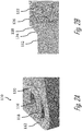
Fig. 2A is a close-up view of a mounting hole in a mounting flange of an electrical connector having a crush rib surrounding the mounting hole in accordance with some embodiments of the invention; -
Fig. 2B is a cross section view of the mounting hole and crush rib ofFig. 2A in accordance with some embodiments of the invention; and -
Fig. 3 is a flow chart of a method of assembling an electrical connector to a panel in accordance with some embodiments of the invention. - An electrical connector, hereinafter referred to as the
connector 110 with a mounting flange, hereinafter referred to as theflange 112, that is similar to theconnector 10 ofFigs. 1A and 1B is presented herein. However, as shown inFigs. 2A and 2B , theconnector 110 has amounting hole 116 extending through theflange 112 is surrounded by an angledannular crush rib 118, rather than having a metal bushing that surrounds the mounting holes as shown inFig. 1B . Thecrush rib 118 sits atop an annular reinforcingboss 120 having a thickness greater than themounting flange 112 that is designed to withstand a clamping force applied to theflange 112 by a fastener (not shown), e.g. a threaded socket head bolt, securing theconnector 110 to a panel (not shown) without damage to theflange 112. Theboss 120 and thecrush rib 118 are integrally formed with theflange 112 and are formed of the same material as theflange 112, e.g. an engineered dielectric polymeric material such as polyamide (NYLON), polybutylene terephthalate (PBT), or acrylonitrile butadiene styrene (ABS). - This
crush rib 118 is located on a side of theflange 112 such that thecrush rib 118 is disposed between theflange 112 and the head of the fastener when theconnector 110 is attached to a panel. Thecrush rib 118 is configured to plastically deform when the clamping force is applied to it by the fastener so that the crush rib 118 deforms toward themounting hole 116 and partially fills themounting hole 116, preferably filling a gap between awall 122 of themounting hole 116 and the fastener. In the case when the fastener is a threaded fastener, the crush rib may also partially fill the threads of the threaded fastener and the friction caused by the interface between thecrush rib 118 and the threads will increase the torque necessary to remove the threaded fastener from themounting hole 116. Thecrush rib 118 will thereby function similarly to a polymer-insert lock nut to inhibit undesired loosing of the fastener in themounting hole 116. - The clamping force applied to deform the crush rib may be in the range of 1.25 N to 2.5 N, e.g. resulting from a torque of 1 N-m to 2 N-m applied to a 4 mm treaded fastener. Filling the gap between the
mounting hole 116 and the fastener also limits radial travel of the fastener in themounting hole 116 which may reduce vibration of the header. Thetop surface 124 of thecrush rib 118 is angled such that the height of thecrush rib 118 decreases as the radial distance from themounting hole 116 increases as shown inFig. 2B . The head of the fastener will interface directly with theboss 120 and thecrush rib 118. Thecrush rib 118 also defines anannular lip 126 having a semicircular cross section that is located at the tip of thecrush rib 118 proximate themounting hole 118 and extending from theinner wall 122. -
Fig. 3 illustrates amethod 200 of assembling an electrical connector to a panel. Themethod 200 includes the following steps: -
STEP 210, INSERT A FASTENER WITHIN A MOUNTING HOLE OF A MOUNTING FLANGE DEFINING THE MOUNTING HOLE EXTENDING THERETHROUGH AND A CRUSH RIB SURROUNDING THE MOUNTING HOLE, includes inserting a fastener within amounting hole 116 of amounting flange 112 defining themounting hole 116 extending therethrough and acrush rib 118 surrounding themounting hole 116; -
STEP 212, APPLYING A CLAMPING FORCE TO THE MOUNTING FLANGE VIA THE FASTENER, includes applying a clamping force to the mountingflange 112 via the fastener; and -
STEP 214, DEFORM THE CRUSH RIB VIA THE CLAMPING FORCE APPLIED BY THE FASTENER SUCH THAT THE DEFORMED CRUSH RIB AT LEAST PARTIALLY FILLS A GAP BETWEEN AN INNER WALL OF THE MOUNTING HOLE AND THE FASTENER, includes deforming thecrush rib 118 via the clamping force applied by the fastener such that thedeformed crush rib 118 at least partially fills a gap between aninner wall 122 of the mountinghole 116 and the fastener. - Accordingly, an
electrical connector 110 with a mountingflange 112 having acrush rib 118 and amethod 200 of assembling an electrical connector to a panel is provided. Thecrush rib 118 allows the elimination of metal bushings which provides a significant cost savings for the electrical connector. Thecrush rib 118 fills the gap between fastener and mountinghole 116 and inhibits radial movement between the fastener and thewall 122 of the mountinghole 116, which reduces undesirable movement between them caused by radial loads, thereby improving vibration performance of theconnector 110. Also, by filling the gap between fastener and mountinghole 116 reduces the environmental contaminant path through the mounting hole is reduced, the need for a split washer may be eliminated, and use of a thread locking adhesive, e.g. LOCKTITE 242, may be unnecessary. Thecrush rib 118 may also serve as an indicator of under torqued or over torqued fasteners based on the degree to which thecrush rib 118 is deformed. - While the exemplary embodiment is an electrical connector, other connector embodiments may be envisioned that are adapted for use with fiber optic cables, pneumatic tubes, hydraulic tubes, or a hybrid connector assembly including two or more of the items listed above.
Claims (15)
- An electrical connector (110), comprising:a mounting flange (112) defining a mounting hole (114) extending therethrough that is configured to receive a threaded fastener; anda deformable crush rib (118) extending from the mounting flange (112) and surrounding the mounting hole (114).
- The electrical connector in accordance with claim 1, wherein the crush rib (118) is angled such that a height of the crush rib (118) decreases as the radial distance from the mounting hole (116) increases.
- The electrical connector in accordance with claim 1 or 2, wherein the crush rib (118) defines an annular lip (124) having a semicircular cross section located proximate the mounting hole (116).
- The electrical connector in accordance any one of the preceding claims, wherein a cylindrical boss (120) surrounds the mounting hole (116) and wherein the crush rib (118) extends from the boss (120).
- The electrical connector in accordance with claim 4, wherein the crush rib (118) is integrally formed with the boss (120).
- The electrical connector in accordance with claim 4 or 5, wherein the crush rib (118) and the boss (120) are formed of the same dielectric polymeric material.
- The electrical connector in accordance any one of the preceding claims, wherein the crush rib (118) is integrally formed with the mounting flange (120).
- The electrical connector in accordance any one of the preceding claims, wherein the crush rib (118) and the mounting flange (112) are formed of the same dielectric polymeric material.
- A method (200) of assembling an electrical connector (110) to a panel, comprising:inserting (210) a fastener within a mounting hole (116) of a mounting flange (112) defining the mounting hole (116) extending therethrough and a crush rib (118) surrounding the mounting hole (116);applying (212) a clamping force to the mounting flange (112) via the fastener; anddeforming (214) the crush rib (118) via the clamping force applied by the fastener such that the deformed crush rib (118) at least partially fills a gap between an inner wall (122) of the mounting hole (116) and the fastener.
- The method (200) in accordance with claim 9, wherein the fastener is a threaded fastener and wherein the deformed crush rib (118) at least partially fills a thread of the threaded fastener.
- The method (200) in accordance with claim 9 or 10, wherein the clamping force is applied (212) by rotating the threaded fastener.
- The method (200) in accordance with any one of the claims 9 to 11, wherein the crush rib (118) is angled such that a height of the crush rib (118) decreases as the radial distance from the mounting hole (116) increases.
- The method (200) in accordance with any one of the claims 9 to 12, wherein the crush rib (118) defines an annular lip (124) having a semicircular cross section located proximate the mounting hole (116).
- The method (200) in accordance with any one of the claims 9 to 13, wherein a cylindrical boss (120) surrounds the mounting hole (116) and wherein the crush rib (118) extends from the boss (120).
- The method in accordance with any one of the claims 9 to 14, wherein the crush rib (118) is integrally formed with the mounting flange (112) and wherein the crush rib (118) and the mounting flange (112) are formed of the same dielectric polymeric material.
Applications Claiming Priority (1)
| Application Number | Priority Date | Filing Date | Title |
|---|---|---|---|
| US201962934086P | 2019-11-12 | 2019-11-12 |
Publications (2)
| Publication Number | Publication Date |
|---|---|
| EP3823108A1 true EP3823108A1 (en) | 2021-05-19 |
| EP3823108B1 EP3823108B1 (en) | 2022-09-07 |
Family
ID=73343888
Family Applications (1)
| Application Number | Title | Priority Date | Filing Date |
|---|---|---|---|
| EP20206890.4A Active EP3823108B1 (en) | 2019-11-12 | 2020-11-11 | Electrical connector with a mounting flange and method of assembling same |
Country Status (4)
| Country | Link |
|---|---|
| US (1) | US11462854B2 (en) |
| EP (1) | EP3823108B1 (en) |
| KR (1) | KR102883564B1 (en) |
| CN (1) | CN112864739A (en) |
Families Citing this family (3)
| Publication number | Priority date | Publication date | Assignee | Title |
|---|---|---|---|---|
| USD1008152S1 (en) * | 2016-09-27 | 2023-12-19 | Daniel Ray Enyeart | Mounting flange |
| USD1008153S1 (en) * | 2017-11-21 | 2023-12-19 | Daniel Ray Enyeart | Mounting flange |
| US20240429543A1 (en) * | 2023-06-26 | 2024-12-26 | Rivian Ip Holdings, Llc | Header apparatus |
Citations (4)
| Publication number | Priority date | Publication date | Assignee | Title |
|---|---|---|---|---|
| EP0709926A1 (en) * | 1994-10-28 | 1996-05-01 | The Whitaker Corporation | A center jackscrew type connector system |
| WO2002055355A2 (en) * | 2001-01-12 | 2002-07-18 | Kelsey-Hayes Company | Coil assembly |
| US20070025866A1 (en) * | 2005-07-27 | 2007-02-01 | Yoshiaki Douyama | Fluid pump assembly |
| DE202006018042U1 (en) * | 2006-11-28 | 2007-05-24 | Hengstler Gmbh | Seal for flange connector |
Family Cites Families (14)
| Publication number | Priority date | Publication date | Assignee | Title |
|---|---|---|---|---|
| JPS58104416U (en) * | 1982-01-11 | 1983-07-15 | デルタ工業株式会社 | Binding device for synthetic resin molded products |
| US5088935A (en) * | 1991-04-05 | 1992-02-18 | Penn Engineering & Manufacturing Corp. | Electrical connector panel |
| KR200213625Y1 (en) * | 2000-09-04 | 2001-02-15 | 나명환 | Anti-Vibration Type Piping Connection Device |
| JP3723114B2 (en) * | 2001-10-03 | 2005-12-07 | Smk株式会社 | Mounting structure of electrical parts to chassis |
| GB2442482A (en) * | 2006-10-05 | 2008-04-09 | Robert Morrison | Pre-determined torque-nut |
| CN101694243B (en) * | 2009-09-30 | 2011-03-30 | 苏州市中新动力设备辅机有限公司 | Sealing structure between high-temperature high-pressure stop valve cover and valve seat |
| ES2565479T3 (en) | 2009-10-26 | 2016-04-05 | Heyco, Inc. | Electrical connectors for photovoltaic installations |
| CN201884421U (en) * | 2010-12-22 | 2011-06-29 | 浙江中通汽车零部件有限公司 | Sealing travelling nut |
| JP6043577B2 (en) * | 2012-10-11 | 2016-12-14 | 矢崎総業株式会社 | Shield connector |
| CN204090416U (en) * | 2014-09-15 | 2015-01-07 | 深圳市四方电气技术有限公司 | Liquid cooling plate radiator and fluid coupler Hermetical connecting structure and electronic equipment |
| KR20160000989U (en) * | 2014-09-18 | 2016-03-28 | 엘에스산전 주식회사 | Electric cunector |
| GB2561233B (en) * | 2017-04-07 | 2020-01-15 | Ford Motor Co | A Gasket Assembly |
| CN209121856U (en) * | 2018-06-26 | 2019-07-19 | 浙江苏泊尔家电制造有限公司 | Cooking apparatus |
| CN209104469U (en) * | 2019-01-09 | 2019-07-12 | 莫仕连接器(成都)有限公司 | Arrangements of electric connection |
-
2020
- 2020-10-07 US US17/064,946 patent/US11462854B2/en active Active
- 2020-11-11 EP EP20206890.4A patent/EP3823108B1/en active Active
- 2020-11-11 KR KR1020200149863A patent/KR102883564B1/en active Active
- 2020-11-12 CN CN202011259451.9A patent/CN112864739A/en active Pending
Patent Citations (4)
| Publication number | Priority date | Publication date | Assignee | Title |
|---|---|---|---|---|
| EP0709926A1 (en) * | 1994-10-28 | 1996-05-01 | The Whitaker Corporation | A center jackscrew type connector system |
| WO2002055355A2 (en) * | 2001-01-12 | 2002-07-18 | Kelsey-Hayes Company | Coil assembly |
| US20070025866A1 (en) * | 2005-07-27 | 2007-02-01 | Yoshiaki Douyama | Fluid pump assembly |
| DE202006018042U1 (en) * | 2006-11-28 | 2007-05-24 | Hengstler Gmbh | Seal for flange connector |
Also Published As
| Publication number | Publication date |
|---|---|
| EP3823108B1 (en) | 2022-09-07 |
| KR20210058700A (en) | 2021-05-24 |
| US20210143574A1 (en) | 2021-05-13 |
| US11462854B2 (en) | 2022-10-04 |
| KR102883564B1 (en) | 2025-11-10 |
| CN112864739A (en) | 2021-05-28 |
Similar Documents
| Publication | Publication Date | Title |
|---|---|---|
| EP3823108B1 (en) | Electrical connector with a mounting flange and method of assembling same | |
| US12503195B2 (en) | Fastening arrangement, in particular for fastening an electric drive to an electric bicycle | |
| KR20060100239A (en) | Assembly for mounting vehicle roof antenna | |
| US10886641B2 (en) | Copper busbar for a contact system | |
| US20160116075A1 (en) | Valve | |
| JP6964140B2 (en) | Grommet | |
| RU2335052C1 (en) | Grounding nut | |
| US5393133A (en) | Brake fluid pressure control apparatus | |
| US5419665A (en) | Non-metallic nut ring | |
| KR102496813B1 (en) | Push nut for vehicle | |
| CN116581623B (en) | Machining and assembling method of anti-withdrawal connector assembly | |
| CN220415980U (en) | Anti-loosening structure for vehicle suspension and vehicle suspension | |
| JP4268554B2 (en) | Machine parts | |
| EP3217481A1 (en) | Electric earth system and earth connection production method | |
| JP6616875B1 (en) | Cable gland | |
| US20250243890A1 (en) | Fastening structure | |
| KR102610772B1 (en) | Earth terminal for grounding | |
| KR102907920B1 (en) | Part fixing bolt for vehicle body | |
| JP3324511B2 (en) | Fixing structure of electrical junction box | |
| JP2015094434A (en) | Fastening structure for dissimilar metal parts | |
| US20240051641A1 (en) | Holding Device for an Electrical Energy Store Integrated into the Frame Tube of an Electric Bicycle | |
| JP5024091B2 (en) | Grommet mounting structure | |
| KR101284428B1 (en) | Insert for plastic pannel of heavy machine | |
| CN122072013A (en) | Studs and methods for top mounting components | |
| CN209250952U (en) | Fixing parts, fixing components and electronics |
Legal Events
| Date | Code | Title | Description |
|---|---|---|---|
| PUAI | Public reference made under article 153(3) epc to a published international application that has entered the european phase |
Free format text: ORIGINAL CODE: 0009012 |
|
| STAA | Information on the status of an ep patent application or granted ep patent |
Free format text: STATUS: THE APPLICATION HAS BEEN PUBLISHED |
|
| AK | Designated contracting states |
Kind code of ref document: A1 Designated state(s): AL AT BE BG CH CY CZ DE DK EE ES FI FR GB GR HR HU IE IS IT LI LT LU LV MC MK MT NL NO PL PT RO RS SE SI SK SM TR |
|
| STAA | Information on the status of an ep patent application or granted ep patent |
Free format text: STATUS: REQUEST FOR EXAMINATION WAS MADE |
|
| 17P | Request for examination filed |
Effective date: 20210728 |
|
| RBV | Designated contracting states (corrected) |
Designated state(s): AL AT BE BG CH CY CZ DE DK EE ES FI FR GB GR HR HU IE IS IT LI LT LU LV MC MK MT NL NO PL PT RO RS SE SI SK SM TR |
|
| GRAP | Despatch of communication of intention to grant a patent |
Free format text: ORIGINAL CODE: EPIDOSNIGR1 |
|
| STAA | Information on the status of an ep patent application or granted ep patent |
Free format text: STATUS: GRANT OF PATENT IS INTENDED |
|
| RIC1 | Information provided on ipc code assigned before grant |
Ipc: F16B 17/00 20060101ALI20211123BHEP Ipc: H01R 13/52 20060101ALI20211123BHEP Ipc: H01R 13/74 20060101AFI20211123BHEP |
|
| INTG | Intention to grant announced |
Effective date: 20211206 |
|
| GRAJ | Information related to disapproval of communication of intention to grant by the applicant or resumption of examination proceedings by the epo deleted |
Free format text: ORIGINAL CODE: EPIDOSDIGR1 |
|
| STAA | Information on the status of an ep patent application or granted ep patent |
Free format text: STATUS: REQUEST FOR EXAMINATION WAS MADE |
|
| GRAP | Despatch of communication of intention to grant a patent |
Free format text: ORIGINAL CODE: EPIDOSNIGR1 |
|
| STAA | Information on the status of an ep patent application or granted ep patent |
Free format text: STATUS: GRANT OF PATENT IS INTENDED |
|
| INTC | Intention to grant announced (deleted) | ||
| INTG | Intention to grant announced |
Effective date: 20220401 |
|
| GRAS | Grant fee paid |
Free format text: ORIGINAL CODE: EPIDOSNIGR3 |
|
| GRAA | (expected) grant |
Free format text: ORIGINAL CODE: 0009210 |
|
| STAA | Information on the status of an ep patent application or granted ep patent |
Free format text: STATUS: THE PATENT HAS BEEN GRANTED |
|
| AK | Designated contracting states |
Kind code of ref document: B1 Designated state(s): AL AT BE BG CH CY CZ DE DK EE ES FI FR GB GR HR HU IE IS IT LI LT LU LV MC MK MT NL NO PL PT RO RS SE SI SK SM TR |
|
| REG | Reference to a national code |
Ref country code: GB Ref legal event code: FG4D |
|
| REG | Reference to a national code |
Ref country code: CH Ref legal event code: EP Ref country code: AT Ref legal event code: REF Ref document number: 1517834 Country of ref document: AT Kind code of ref document: T Effective date: 20220915 |
|
| REG | Reference to a national code |
Ref country code: IE Ref legal event code: FG4D |
|
| REG | Reference to a national code |
Ref country code: DE Ref legal event code: R096 Ref document number: 602020004982 Country of ref document: DE |
|
| REG | Reference to a national code |
Ref country code: LT Ref legal event code: MG9D |
|
| REG | Reference to a national code |
Ref country code: NL Ref legal event code: MP Effective date: 20220907 |
|
| PG25 | Lapsed in a contracting state [announced via postgrant information from national office to epo] |
Ref country code: SE Free format text: LAPSE BECAUSE OF FAILURE TO SUBMIT A TRANSLATION OF THE DESCRIPTION OR TO PAY THE FEE WITHIN THE PRESCRIBED TIME-LIMIT Effective date: 20220907 Ref country code: RS Free format text: LAPSE BECAUSE OF FAILURE TO SUBMIT A TRANSLATION OF THE DESCRIPTION OR TO PAY THE FEE WITHIN THE PRESCRIBED TIME-LIMIT Effective date: 20220907 Ref country code: NO Free format text: LAPSE BECAUSE OF FAILURE TO SUBMIT A TRANSLATION OF THE DESCRIPTION OR TO PAY THE FEE WITHIN THE PRESCRIBED TIME-LIMIT Effective date: 20221207 Ref country code: LV Free format text: LAPSE BECAUSE OF FAILURE TO SUBMIT A TRANSLATION OF THE DESCRIPTION OR TO PAY THE FEE WITHIN THE PRESCRIBED TIME-LIMIT Effective date: 20220907 Ref country code: LT Free format text: LAPSE BECAUSE OF FAILURE TO SUBMIT A TRANSLATION OF THE DESCRIPTION OR TO PAY THE FEE WITHIN THE PRESCRIBED TIME-LIMIT Effective date: 20220907 Ref country code: FI Free format text: LAPSE BECAUSE OF FAILURE TO SUBMIT A TRANSLATION OF THE DESCRIPTION OR TO PAY THE FEE WITHIN THE PRESCRIBED TIME-LIMIT Effective date: 20220907 |
|
| REG | Reference to a national code |
Ref country code: AT Ref legal event code: MK05 Ref document number: 1517834 Country of ref document: AT Kind code of ref document: T Effective date: 20220907 |
|
| PG25 | Lapsed in a contracting state [announced via postgrant information from national office to epo] |
Ref country code: HR Free format text: LAPSE BECAUSE OF FAILURE TO SUBMIT A TRANSLATION OF THE DESCRIPTION OR TO PAY THE FEE WITHIN THE PRESCRIBED TIME-LIMIT Effective date: 20220907 Ref country code: GR Free format text: LAPSE BECAUSE OF FAILURE TO SUBMIT A TRANSLATION OF THE DESCRIPTION OR TO PAY THE FEE WITHIN THE PRESCRIBED TIME-LIMIT Effective date: 20221208 |
|
| RAP4 | Party data changed (patent owner data changed or rights of a patent transferred) |
Owner name: APTIV TECHNOLOGIES LIMITED |
|
| PG25 | Lapsed in a contracting state [announced via postgrant information from national office to epo] |
Ref country code: SM Free format text: LAPSE BECAUSE OF FAILURE TO SUBMIT A TRANSLATION OF THE DESCRIPTION OR TO PAY THE FEE WITHIN THE PRESCRIBED TIME-LIMIT Effective date: 20220907 Ref country code: RO Free format text: LAPSE BECAUSE OF FAILURE TO SUBMIT A TRANSLATION OF THE DESCRIPTION OR TO PAY THE FEE WITHIN THE PRESCRIBED TIME-LIMIT Effective date: 20220907 Ref country code: PT Free format text: LAPSE BECAUSE OF FAILURE TO SUBMIT A TRANSLATION OF THE DESCRIPTION OR TO PAY THE FEE WITHIN THE PRESCRIBED TIME-LIMIT Effective date: 20230109 Ref country code: ES Free format text: LAPSE BECAUSE OF FAILURE TO SUBMIT A TRANSLATION OF THE DESCRIPTION OR TO PAY THE FEE WITHIN THE PRESCRIBED TIME-LIMIT Effective date: 20220907 Ref country code: CZ Free format text: LAPSE BECAUSE OF FAILURE TO SUBMIT A TRANSLATION OF THE DESCRIPTION OR TO PAY THE FEE WITHIN THE PRESCRIBED TIME-LIMIT Effective date: 20220907 Ref country code: AT Free format text: LAPSE BECAUSE OF FAILURE TO SUBMIT A TRANSLATION OF THE DESCRIPTION OR TO PAY THE FEE WITHIN THE PRESCRIBED TIME-LIMIT Effective date: 20220907 |
|
| PG25 | Lapsed in a contracting state [announced via postgrant information from national office to epo] |
Ref country code: SK Free format text: LAPSE BECAUSE OF FAILURE TO SUBMIT A TRANSLATION OF THE DESCRIPTION OR TO PAY THE FEE WITHIN THE PRESCRIBED TIME-LIMIT Effective date: 20220907 Ref country code: PL Free format text: LAPSE BECAUSE OF FAILURE TO SUBMIT A TRANSLATION OF THE DESCRIPTION OR TO PAY THE FEE WITHIN THE PRESCRIBED TIME-LIMIT Effective date: 20220907 Ref country code: IS Free format text: LAPSE BECAUSE OF FAILURE TO SUBMIT A TRANSLATION OF THE DESCRIPTION OR TO PAY THE FEE WITHIN THE PRESCRIBED TIME-LIMIT Effective date: 20230107 Ref country code: EE Free format text: LAPSE BECAUSE OF FAILURE TO SUBMIT A TRANSLATION OF THE DESCRIPTION OR TO PAY THE FEE WITHIN THE PRESCRIBED TIME-LIMIT Effective date: 20220907 |
|
| REG | Reference to a national code |
Ref country code: DE Ref legal event code: R097 Ref document number: 602020004982 Country of ref document: DE |
|
| P01 | Opt-out of the competence of the unified patent court (upc) registered |
Effective date: 20230424 |
|
| PG25 | Lapsed in a contracting state [announced via postgrant information from national office to epo] |
Ref country code: NL Free format text: LAPSE BECAUSE OF FAILURE TO SUBMIT A TRANSLATION OF THE DESCRIPTION OR TO PAY THE FEE WITHIN THE PRESCRIBED TIME-LIMIT Effective date: 20220907 Ref country code: MC Free format text: LAPSE BECAUSE OF FAILURE TO SUBMIT A TRANSLATION OF THE DESCRIPTION OR TO PAY THE FEE WITHIN THE PRESCRIBED TIME-LIMIT Effective date: 20220907 Ref country code: AL Free format text: LAPSE BECAUSE OF FAILURE TO SUBMIT A TRANSLATION OF THE DESCRIPTION OR TO PAY THE FEE WITHIN THE PRESCRIBED TIME-LIMIT Effective date: 20220907 |
|
| PLBE | No opposition filed within time limit |
Free format text: ORIGINAL CODE: 0009261 |
|
| STAA | Information on the status of an ep patent application or granted ep patent |
Free format text: STATUS: NO OPPOSITION FILED WITHIN TIME LIMIT |
|
| REG | Reference to a national code |
Ref country code: BE Ref legal event code: MM Effective date: 20221130 |
|
| PG25 | Lapsed in a contracting state [announced via postgrant information from national office to epo] |
Ref country code: DK Free format text: LAPSE BECAUSE OF FAILURE TO SUBMIT A TRANSLATION OF THE DESCRIPTION OR TO PAY THE FEE WITHIN THE PRESCRIBED TIME-LIMIT Effective date: 20220907 |
|
| 26N | No opposition filed |
Effective date: 20230608 |
|
| PG25 | Lapsed in a contracting state [announced via postgrant information from national office to epo] |
Ref country code: SI Free format text: LAPSE BECAUSE OF FAILURE TO SUBMIT A TRANSLATION OF THE DESCRIPTION OR TO PAY THE FEE WITHIN THE PRESCRIBED TIME-LIMIT Effective date: 20220907 Ref country code: LU Free format text: LAPSE BECAUSE OF NON-PAYMENT OF DUE FEES Effective date: 20221111 |
|
| PG25 | Lapsed in a contracting state [announced via postgrant information from national office to epo] |
Ref country code: IE Free format text: LAPSE BECAUSE OF NON-PAYMENT OF DUE FEES Effective date: 20221111 |
|
| PG25 | Lapsed in a contracting state [announced via postgrant information from national office to epo] |
Ref country code: BE Free format text: LAPSE BECAUSE OF NON-PAYMENT OF DUE FEES Effective date: 20221130 |
|
| PG25 | Lapsed in a contracting state [announced via postgrant information from national office to epo] |
Ref country code: CY Free format text: LAPSE BECAUSE OF FAILURE TO SUBMIT A TRANSLATION OF THE DESCRIPTION OR TO PAY THE FEE WITHIN THE PRESCRIBED TIME-LIMIT Effective date: 20220907 |
|
| PG25 | Lapsed in a contracting state [announced via postgrant information from national office to epo] |
Ref country code: MK Free format text: LAPSE BECAUSE OF FAILURE TO SUBMIT A TRANSLATION OF THE DESCRIPTION OR TO PAY THE FEE WITHIN THE PRESCRIBED TIME-LIMIT Effective date: 20220907 Ref country code: IT Free format text: LAPSE BECAUSE OF FAILURE TO SUBMIT A TRANSLATION OF THE DESCRIPTION OR TO PAY THE FEE WITHIN THE PRESCRIBED TIME-LIMIT Effective date: 20220907 |
|
| REG | Reference to a national code |
Ref country code: CH Ref legal event code: PL |
|
| PG25 | Lapsed in a contracting state [announced via postgrant information from national office to epo] |
Ref country code: CH Free format text: LAPSE BECAUSE OF NON-PAYMENT OF DUE FEES Effective date: 20231130 |
|
| PG25 | Lapsed in a contracting state [announced via postgrant information from national office to epo] |
Ref country code: HU Free format text: LAPSE BECAUSE OF FAILURE TO SUBMIT A TRANSLATION OF THE DESCRIPTION OR TO PAY THE FEE WITHIN THE PRESCRIBED TIME-LIMIT; INVALID AB INITIO Effective date: 20201111 Ref country code: CH Free format text: LAPSE BECAUSE OF NON-PAYMENT OF DUE FEES Effective date: 20231130 Ref country code: BG Free format text: LAPSE BECAUSE OF FAILURE TO SUBMIT A TRANSLATION OF THE DESCRIPTION OR TO PAY THE FEE WITHIN THE PRESCRIBED TIME-LIMIT Effective date: 20220907 |
|
| PG25 | Lapsed in a contracting state [announced via postgrant information from national office to epo] |
Ref country code: MT Free format text: LAPSE BECAUSE OF FAILURE TO SUBMIT A TRANSLATION OF THE DESCRIPTION OR TO PAY THE FEE WITHIN THE PRESCRIBED TIME-LIMIT Effective date: 20220907 |
|
| REG | Reference to a national code |
Ref country code: DE Ref legal event code: R081 Ref document number: 602020004982 Country of ref document: DE Owner name: APTIV TECHNOLOGIES AG, CH Free format text: FORMER OWNER: APTIV TECHNOLOGIES LIMITED, ST. MICHAEL, BB |
|
| PG25 | Lapsed in a contracting state [announced via postgrant information from national office to epo] |
Ref country code: TR Free format text: LAPSE BECAUSE OF FAILURE TO SUBMIT A TRANSLATION OF THE DESCRIPTION OR TO PAY THE FEE WITHIN THE PRESCRIBED TIME-LIMIT Effective date: 20220907 |
|
| PGFP | Annual fee paid to national office [announced via postgrant information from national office to epo] |
Ref country code: DE Payment date: 20251010 Year of fee payment: 6 |
|
| PGFP | Annual fee paid to national office [announced via postgrant information from national office to epo] |
Ref country code: GB Payment date: 20251015 Year of fee payment: 6 |
|
| PGFP | Annual fee paid to national office [announced via postgrant information from national office to epo] |
Ref country code: FR Payment date: 20251014 Year of fee payment: 6 |