EP3822852B1 - Verfahren, vorrichtung, computerprogrammprodukt und computerlesbarer datenträger zum trainieren eines routenplannungsmodells - Google Patents
Verfahren, vorrichtung, computerprogrammprodukt und computerlesbarer datenträger zum trainieren eines routenplannungsmodells Download PDFInfo
- Publication number
- EP3822852B1 EP3822852B1 EP21166377.8A EP21166377A EP3822852B1 EP 3822852 B1 EP3822852 B1 EP 3822852B1 EP 21166377 A EP21166377 A EP 21166377A EP 3822852 B1 EP3822852 B1 EP 3822852B1
- Authority
- EP
- European Patent Office
- Prior art keywords
- trajectory
- vehicle
- image
- area
- determining
- Prior art date
- Legal status (The legal status is an assumption and is not a legal conclusion. Google has not performed a legal analysis and makes no representation as to the accuracy of the status listed.)
- Active
Links
- 238000000034 method Methods 0.000 title claims description 65
- 238000012549 training Methods 0.000 title claims description 39
- 238000004590 computer program Methods 0.000 claims description 15
- 239000011159 matrix material Substances 0.000 claims description 14
- 230000008569 process Effects 0.000 claims description 11
- 230000004044 response Effects 0.000 claims description 4
- 230000004913 activation Effects 0.000 claims description 3
- 238000003062 neural network model Methods 0.000 claims description 2
- 238000010586 diagram Methods 0.000 description 21
- 238000012545 processing Methods 0.000 description 20
- 238000013528 artificial neural network Methods 0.000 description 12
- 230000006870 function Effects 0.000 description 8
- 238000013527 convolutional neural network Methods 0.000 description 7
- 238000004891 communication Methods 0.000 description 5
- 230000005540 biological transmission Effects 0.000 description 4
- 238000004364 calculation method Methods 0.000 description 3
- 230000003287 optical effect Effects 0.000 description 3
- 238000011176 pooling Methods 0.000 description 3
- 230000002441 reversible effect Effects 0.000 description 3
- 238000003491 array Methods 0.000 description 2
- 238000004422 calculation algorithm Methods 0.000 description 2
- 238000001514 detection method Methods 0.000 description 2
- 239000000835 fiber Substances 0.000 description 2
- 230000001902 propagating effect Effects 0.000 description 2
- 241000251468 Actinopterygii Species 0.000 description 1
- RYGMFSIKBFXOCR-UHFFFAOYSA-N Copper Chemical compound [Cu] RYGMFSIKBFXOCR-UHFFFAOYSA-N 0.000 description 1
- 230000001413 cellular effect Effects 0.000 description 1
- 229910052802 copper Inorganic materials 0.000 description 1
- 239000010949 copper Substances 0.000 description 1
- 238000013136 deep learning model Methods 0.000 description 1
- 238000011161 development Methods 0.000 description 1
- 238000005516 engineering process Methods 0.000 description 1
- 230000007613 environmental effect Effects 0.000 description 1
- 230000001788 irregular Effects 0.000 description 1
- 230000007774 longterm Effects 0.000 description 1
- 238000004519 manufacturing process Methods 0.000 description 1
- 230000000873 masking effect Effects 0.000 description 1
- 230000002093 peripheral effect Effects 0.000 description 1
- 230000000306 recurrent effect Effects 0.000 description 1
- 239000004065 semiconductor Substances 0.000 description 1
- 239000007787 solid Substances 0.000 description 1
- 230000003068 static effect Effects 0.000 description 1
Images


Classifications
-
- G—PHYSICS
- G06—COMPUTING; CALCULATING OR COUNTING
- G06V—IMAGE OR VIDEO RECOGNITION OR UNDERSTANDING
- G06V20/00—Scenes; Scene-specific elements
- G06V20/50—Context or environment of the image
- G06V20/56—Context or environment of the image exterior to a vehicle by using sensors mounted on the vehicle
-
- G—PHYSICS
- G06—COMPUTING; CALCULATING OR COUNTING
- G06N—COMPUTING ARRANGEMENTS BASED ON SPECIFIC COMPUTATIONAL MODELS
- G06N3/00—Computing arrangements based on biological models
- G06N3/02—Neural networks
- G06N3/08—Learning methods
-
- G05D1/249—
-
- B—PERFORMING OPERATIONS; TRANSPORTING
- B60—VEHICLES IN GENERAL
- B60W—CONJOINT CONTROL OF VEHICLE SUB-UNITS OF DIFFERENT TYPE OR DIFFERENT FUNCTION; CONTROL SYSTEMS SPECIALLY ADAPTED FOR HYBRID VEHICLES; ROAD VEHICLE DRIVE CONTROL SYSTEMS FOR PURPOSES NOT RELATED TO THE CONTROL OF A PARTICULAR SUB-UNIT
- B60W60/00—Drive control systems specially adapted for autonomous road vehicles
- B60W60/001—Planning or execution of driving tasks
-
- G—PHYSICS
- G01—MEASURING; TESTING
- G01C—MEASURING DISTANCES, LEVELS OR BEARINGS; SURVEYING; NAVIGATION; GYROSCOPIC INSTRUMENTS; PHOTOGRAMMETRY OR VIDEOGRAMMETRY
- G01C21/00—Navigation; Navigational instruments not provided for in groups G01C1/00 - G01C19/00
- G01C21/26—Navigation; Navigational instruments not provided for in groups G01C1/00 - G01C19/00 specially adapted for navigation in a road network
- G01C21/34—Route searching; Route guidance
- G01C21/3407—Route searching; Route guidance specially adapted for specific applications
-
- G—PHYSICS
- G06—COMPUTING; CALCULATING OR COUNTING
- G06F—ELECTRIC DIGITAL DATA PROCESSING
- G06F18/00—Pattern recognition
- G06F18/20—Analysing
- G06F18/24—Classification techniques
-
- G—PHYSICS
- G06—COMPUTING; CALCULATING OR COUNTING
- G06N—COMPUTING ARRANGEMENTS BASED ON SPECIFIC COMPUTATIONAL MODELS
- G06N20/00—Machine learning
-
- G—PHYSICS
- G06—COMPUTING; CALCULATING OR COUNTING
- G06N—COMPUTING ARRANGEMENTS BASED ON SPECIFIC COMPUTATIONAL MODELS
- G06N3/00—Computing arrangements based on biological models
- G06N3/02—Neural networks
- G06N3/04—Architecture, e.g. interconnection topology
- G06N3/045—Combinations of networks
-
- G—PHYSICS
- G06—COMPUTING; CALCULATING OR COUNTING
- G06N—COMPUTING ARRANGEMENTS BASED ON SPECIFIC COMPUTATIONAL MODELS
- G06N3/00—Computing arrangements based on biological models
- G06N3/02—Neural networks
- G06N3/08—Learning methods
- G06N3/084—Backpropagation, e.g. using gradient descent
-
- G—PHYSICS
- G06—COMPUTING; CALCULATING OR COUNTING
- G06N—COMPUTING ARRANGEMENTS BASED ON SPECIFIC COMPUTATIONAL MODELS
- G06N5/00—Computing arrangements using knowledge-based models
- G06N5/04—Inference or reasoning models
-
- G—PHYSICS
- G06—COMPUTING; CALCULATING OR COUNTING
- G06V—IMAGE OR VIDEO RECOGNITION OR UNDERSTANDING
- G06V10/00—Arrangements for image or video recognition or understanding
- G06V10/70—Arrangements for image or video recognition or understanding using pattern recognition or machine learning
- G06V10/82—Arrangements for image or video recognition or understanding using pattern recognition or machine learning using neural networks
-
- B—PERFORMING OPERATIONS; TRANSPORTING
- B60—VEHICLES IN GENERAL
- B60W—CONJOINT CONTROL OF VEHICLE SUB-UNITS OF DIFFERENT TYPE OR DIFFERENT FUNCTION; CONTROL SYSTEMS SPECIALLY ADAPTED FOR HYBRID VEHICLES; ROAD VEHICLE DRIVE CONTROL SYSTEMS FOR PURPOSES NOT RELATED TO THE CONTROL OF A PARTICULAR SUB-UNIT
- B60W2420/00—Indexing codes relating to the type of sensors based on the principle of their operation
- B60W2420/40—Photo or light sensitive means, e.g. infrared sensors
- B60W2420/403—Image sensing, e.g. optical camera
-
- B—PERFORMING OPERATIONS; TRANSPORTING
- B60—VEHICLES IN GENERAL
- B60W—CONJOINT CONTROL OF VEHICLE SUB-UNITS OF DIFFERENT TYPE OR DIFFERENT FUNCTION; CONTROL SYSTEMS SPECIALLY ADAPTED FOR HYBRID VEHICLES; ROAD VEHICLE DRIVE CONTROL SYSTEMS FOR PURPOSES NOT RELATED TO THE CONTROL OF A PARTICULAR SUB-UNIT
- B60W2554/00—Input parameters relating to objects
- B60W2554/20—Static objects
-
- B—PERFORMING OPERATIONS; TRANSPORTING
- B60—VEHICLES IN GENERAL
- B60W—CONJOINT CONTROL OF VEHICLE SUB-UNITS OF DIFFERENT TYPE OR DIFFERENT FUNCTION; CONTROL SYSTEMS SPECIALLY ADAPTED FOR HYBRID VEHICLES; ROAD VEHICLE DRIVE CONTROL SYSTEMS FOR PURPOSES NOT RELATED TO THE CONTROL OF A PARTICULAR SUB-UNIT
- B60W2554/00—Input parameters relating to objects
- B60W2554/40—Dynamic objects, e.g. animals, windblown objects
- B60W2554/402—Type
- B60W2554/4029—Pedestrians
-
- B—PERFORMING OPERATIONS; TRANSPORTING
- B60—VEHICLES IN GENERAL
- B60W—CONJOINT CONTROL OF VEHICLE SUB-UNITS OF DIFFERENT TYPE OR DIFFERENT FUNCTION; CONTROL SYSTEMS SPECIALLY ADAPTED FOR HYBRID VEHICLES; ROAD VEHICLE DRIVE CONTROL SYSTEMS FOR PURPOSES NOT RELATED TO THE CONTROL OF A PARTICULAR SUB-UNIT
- B60W2555/00—Input parameters relating to exterior conditions, not covered by groups B60W2552/00, B60W2554/00
- B60W2555/60—Traffic rules, e.g. speed limits or right of way
-
- G—PHYSICS
- G06—COMPUTING; CALCULATING OR COUNTING
- G06N—COMPUTING ARRANGEMENTS BASED ON SPECIFIC COMPUTATIONAL MODELS
- G06N20/00—Machine learning
- G06N20/10—Machine learning using kernel methods, e.g. support vector machines [SVM]
-
- G—PHYSICS
- G06—COMPUTING; CALCULATING OR COUNTING
- G06N—COMPUTING ARRANGEMENTS BASED ON SPECIFIC COMPUTATIONAL MODELS
- G06N3/00—Computing arrangements based on biological models
- G06N3/02—Neural networks
- G06N3/04—Architecture, e.g. interconnection topology
- G06N3/044—Recurrent networks, e.g. Hopfield networks
-
- G—PHYSICS
- G06—COMPUTING; CALCULATING OR COUNTING
- G06N—COMPUTING ARRANGEMENTS BASED ON SPECIFIC COMPUTATIONAL MODELS
- G06N5/00—Computing arrangements using knowledge-based models
- G06N5/01—Dynamic search techniques; Heuristics; Dynamic trees; Branch-and-bound
-
- G—PHYSICS
- G06—COMPUTING; CALCULATING OR COUNTING
- G06N—COMPUTING ARRANGEMENTS BASED ON SPECIFIC COMPUTATIONAL MODELS
- G06N7/00—Computing arrangements based on specific mathematical models
- G06N7/01—Probabilistic graphical models, e.g. probabilistic networks
Definitions
- Embodiments of the present invention relate to the field of autonomous driving, and more particularly, to a method, apparatus, computer storage medium and program for training a trajectory planning model.
- the neural networks is trained by inputting images thereto such that it may obtain accurate and reliable cruise paths.
- the input images include both road information related to the path planning, and interference information which is not related to the path planning, such as distant buildings, vehicles, and pedestrians. Due to a limited amount of computation of the neural network and a limited amount of data and network capacity, the interference information will increase the computation cost of the neural network and consume a large amount of resources. Therefore, there is a need to find a low-cost, fast and efficient path planning training method to improve the accuracy of path planning.
- a neural network training system can train the trajectory planning neural network system on the multiple training data sets.
- Each training data set can include: (i) a first training input that characterizes a set of waypoints that represent respective locations of a vehicle at each of a series of first time steps, (ii) a second training input that characterizes at least one of (a) environmental data that represents a current state of an environment of the vehicle or (b) navigation data that represents a planned navigation route for the vehicle, and (iii) a target output characterizing a waypoint that represents a target location of the vehicle at a second time step that follows the series of first time steps.
- US 10 007 269 B1 discloses a collision-avoidance system for use with an autonomous-capable vehicle can continuously receive image frames captured of the roadway to determine drivable space in a forward direction of the vehicle.
- the system can determine, for each image frame, whether individual regions of the image frame depict drivable space.
- the system can do so using machine-learned image recognition algorithms such as convolutional neural networks generated using extensive training data. Using such techniques, the system can label regions of the image frames as corresponding to drivable space or non-drivable space.
- a scheme for a training trajectory planning model and determining a trajectory of a vehicle are provided.
- a method of training a trajectory planning model includes obtaining an image of a physical environment in which the vehicle is located via at least one sensor of the vehicle, the image including a plurality of objects surrounding the vehicle; obtaining a feature chart indicating a plurality of initial trajectory points of the vehicle in the image by a trajectory planning model based on the image; identifying the image to determine a first area in the image associated with a road object in the plurality of objects and a second area in the image associated with a non-road object in the plurality of obj ects; determining a planning trajectory point based on a positional relationship of the plurality of initial trajectory points with respect to the first area and the second area; and training the trajectory planning model based on the planning trajectory point and the actual trajectory point of the vehicle.
- a method of determining a trajectory of a vehicle according to claim 7 includes obtaining an image of a physical environment in which the vehicle is located via at least one sensor of the vehicle; and determining a trajectory of the vehicle by a trajectory planning model based on the image, where the trajectory planning model is trained according to the method of the first aspect.
- an apparatus for training a trajectory planning model includes an image obtaining module configured to obtain an image of a physical environment in which the vehicle is located via at least one sensor of the vehicle, the image including a plurality of objects surrounding the vehicle; a feature chart determining module configured to obtain a feature chart by a trajectory planning model based on the image, the feature chart indicating a plurality of initial trajectory points of the vehicle in the image; an image identifying module configured to identify the image to determine a first area in the image associated with a road object in the plurality of objects and a second area in the image associated with a non-road object in the plurality of objects; a planning trajectory determining module configured to determine a planning trajectory point based on a positional relationship of the plurality of initial trajectory points with respect to the first area and the second area; and a trajectory planning training module configured to train the trajectory planning model based on the planning track points and the actual trajectory points of the vehicle.
- an apparatus for determining a trajectory of a vehicle includes an image determining module configured to obtain an image of a physical environment in which the vehicle is located via at least one sensor of the vehicle; and a trajectory determining module configured to determine a trajectory of the vehicle by the trajectory planning model based on the image, where the trajectory planning model is trained according to the apparatus of the third aspect.
- an electronic device including one or more processors; and storage means for storing one or more programs, when executed by one or more processors, the one or more programs enable the one or more processors to implement the method according to the first aspect of the present invention.
- an electronic device including one or more processors; and storage means for storing one or more programs, when executed by one or more processors, the one or more programs enable the one or more processors to implement the method according to the second aspect of the present invention.
- a computer readable storage medium according to claim 12 having a computer program stored thereon which, when executed by a processor, implements the method according to the first aspect of the present invention.
- a computer readable storage medium having a computer program stored thereon which, when executed by a processor, implements the method according to the second aspect of the present invention.
- model learns from the training data an association between a corresponding input and an output, so that a given input is processed to generate a corresponding output based on the obtained parameter set after completion of the training.
- model is referred to as "neural network,” “learning model,” “learning network,” or “network.” These terms are used interchangeably herein.
- a scheme of training a trajectory planning model is proposed.
- an image of the physical environment surrounding the vehicle is first obtained, including, for example, an object associated with a road (e.g., a driving lane) and an object associated with a non-road (other vehicles, pedestrians, surrounding scenery).
- the above image is input to a trajectory planning model to be trained to obtain a high-level feature chart including initial trajectory points, and the same image is identified to determine an area associated with the road ("road area”) and an area not associated with the road (“non-road area”).
- the initial trajectory points in the high-level feature chart are compared with the road area and the non-road area to determine which initial trajectory point needs to be focused, so that the initially planned trajectory points are obtained.
- the preliminarily planned trajectory points are compared with the real trajectory, and the trajectory planning model is trained through continuous iterations of the above process.
- FIG. 1 illustrates a schematic diagram of an example environment 100 in which various embodiments of the present invention may be implemented.
- the environment 100 illustrated in FIG. 1 is merely exemplary and should not constitute any limitation on the functionality and scope of the implementations described in this invention.
- the environment 100 includes a vehicle 104 driving on a road.
- the vehicle 104 may be any type of vehicle that may carry people and/or objects and move through a power system such as an engine, including, but not limited to, a car, truck, bus, electric vehicle, motorcycle, RV, train, and the like.
- one or more of the vehicles 104 in the environment 100 may be vehicles with certain autonomous driving capabilities, such vehicles being also referred to as unmanned vehicles.
- the vehicle 104 may also be a vehicle that does not have an autopilot capability.
- the vehicle 104 may be communicatively coupled to the computing device 102. Although shown as a separate entity, the computing device 102 may be embedded in the vehicle 104. The computing device 102 may also be an entity external to vehicle 104 and may communicate with the vehicle 104 via a wireless network.
- the computing device 102 may be any computing-capable device. As a non-limiting example, the computing device 102 may be any type of fixed computing device, mobile computing device, or portable computing device, including, but not limited to, a desktop computer, a laptop computer, a notebook computer, a tablet computer, a multimedia computer, a mobile phone, and the like; all or a portion of the components of the computing device 102 may be distributed over the cloud.
- the computing device 102 includes at least a processor, a memory, and other components typically present in a general purpose computer to perform functions like computing, storage, communication, control, etc.
- the vehicle 104 also includes at least one sensor 105 configured to obtain an image 110 of the physical environment in which the vehicle 104 is located.
- the sensor 105 may be an image sensor that obtains an image 110 of the environment in which the vehicle 104 is located by computer vision techniques.
- the image 110 is a frame of the video 101.
- video 101 may also include other frames, and the image processing according to the present invention may be performed on the other frames.
- the image 110 may also be a still image taken by a camera.
- the image 110 may be captured by one forward wide-angle camera and four fish eye cameras.
- the image 110 may also be obtained by any suitable means.
- the image 110 is processed by the computing device 102.
- the computing device 102 may utilize image identification techniques (e.g., trained 2D identification models) to determine one or more objects in the image 110.
- the computing device 102 may also utilize the trajectory planning model 103 to determine the trajectory of the driving path of the vehicle 104.
- the trajectory planning model 103 includes any type of models capable of performing path trajectory planning. Depending on the particular path planning task, the configuration and training methods of the trajectory planning model 103 may be different.
- the trajectory planning model 103 is a deep learning/neural network model, such as a convolutional neural network (CNN), a recurrent neural network (RNN), and the like.
- CNN convolutional neural network
- RNN recurrent neural network
- the trajectory planning model 103 while shown as a separate entity, may also be implemented in the computing device 102.
- FIG. 2 illustrates a flow diagram of a method 200 for training the trajectory planning model according to embodiments of the present invention.
- the method 200 may be implemented by the computing device 102 in FIG. 1 .
- the method 200 will be described with reference to the example environment 100 of FIG. 1 .
- the computing device 102 obtains the image 110 of the physical environment in which the vehicle 104 is located by using at least one sensor 105 of the vehicle 104.
- the image 110 in front of the vehicle 104 may be obtained by using a camera mounted inside or outside the vehicle 104 when the vehicle 104 is driving to a certain position.
- the image 110 may reflect a road situation of an intersection in front of the vehicle 104, the image 110 includes objects 111-116 in which the object 111 is shown as a vehicle driving on the road, the object 112 is shown as a pedestrian crossing the road, the object 113 is shown as a tree on the road side, the object 114 is shown as a traffic sign, the object 115 is shown as a building at a distant position, and the object 116 is shown as marking lines on the road and the road.
- the number and type of the objects included in the image 110 shown in FIG. 1 are exemplary only and do not intend to be a limitation.
- the image 110 may include any number and type of objects.
- the computing device 102 may communicate with one or more devices which are external to the vehicle 104 and associated with the physical environment in which vehicle 104 is located, to obtain the image 110.
- the computing device 102 may communicate with a roadside camera around the location of the vehicle 104 to obtain the image 110.
- network technologies well known in the art for example, cellular networks (e.g., the fifth generation (5G) network, Long Term Evolution (LTE) network, the third generation (3G) network, Code Division Multiple Access (CDMA) network, etc.), public land mobile network (PLMN), local area network (LAN), wide area network (WAN), metropolitan area network (MAN), telephone network (e.g., Public Switched Telephone Network (PSTN)), private network, ad hoc network, intranet, the Internet, fiber-optic-based network, etc., and/or combinations of these or other types of networks) may be employed to establish connections of the computing device 102, the vehicle 104 to roadside cameras, and will not be described in detail herein.
- 5G fifth generation
- LTE Long Term Evolution
- 3G Third generation
- CDMA Code Division Multiple Access
- PLMN public land mobile network
- LAN local area network
- WAN wide area network
- MAN metropolitan area network
- PSTN Public Switched Telephone Network
- private network e.g., Public
- the computing device 102 obtains a feature chart via the trajectory planning model 103 based on the image 110.
- the trajectory planning model 103 may be a convolutional neural network trained by a certain amount of data sets that may output initial trajectory points of the vehicle 104. For example, the forward wide-angle camera image of the vehicle 104 and the trajectory driving by the human driver may be recorded, then the trajectory may be projected onto each of the obtained image, and then input the image to the convolutional neural network for learning by the convolutional neural network.
- a feature chart may also be obtained from an untrained trajectory planning model 103 provided with initial parameters.
- the computing device 102 inputs the image 110 into the trajectory planning model 103, the image is subjected to convolution calculation, Full connection (FC) calculations, pooling calculations to obtain the feature chart.
- the feature chart may be a high level feature chart closest to the output result. As shown in FIG. 1 , the feature chart includes a plurality of initial trajectory points 117 that constitute the driving path of the vehicle 104.
- the computing device 102 identifies the image to determine a first area in the image 110 associated with a road object in the plurality of objects and a second area in the image 110 associated with a non-road object in the plurality of objects. For example, the computing device 102 determines the vehicle 111, the pedestrian 112, the tree 113, the sign 114, the structure 115, the marking line on the road, and the road 116 therein by identifying the image 110.
- the objects 111-115 are non-road objects and the object 116 is a road object.
- the area associated with the object may be an area within the contour of the object, or may be a polygonal area formed by a peripheral tangent of an irregular contour of the object.
- the first area associated with the road object may be referred to as a driveable area
- the second area associated with a non-road object may be referred to as a non-driveable area.
- the computing device 102 obtains a depth chart based on the trained depth estimation network.
- the depth chart is also referred to as a distance chart, referring to an image that takes the distance from the sensor 105 to each point in the image 110 as a pixel value, i.e., each pixel value in the depth chart represents the distance between a certain point in the image 110 and the sensor 105 or the vehicle 104. Then, the computing device 102 determines the first area and the second area, that is, the driveable area and the non-driveable area, based on the distance.
- the depth estimation network may be a multi-view based depth estimation, a single-view based depth estimation, a binocular image based depth estimation, or a monocular image-based depth estimation, there is no limitation herein.
- the depth chart may be subjected to an image masking process to obtain a drivable area, the mask being a two-dimensional matrix array having a value of 1 corresponding to the first area and a value of o corresponding to the second area, the mask being multiplied by the image 110 to obtain the drivable area.
- the computing device 102 may detect and directly classify objects in the image 110 based on a detection and classification device.
- the detection and classification device for example, a multi-classifier or a binary classifier, may classify the detected object into any suitable category, e.g., may be classified as a human being, a vehicle, a plant, an identification, a road, etc.
- the computing device may then directly determine the drivable area and the non-drivable area by the above classification.
- the determination of the driveable area and the non-driveable area may be made using the existing or future developed techniques, and this invention is not limited thereto.
- the computing device 102 determines planning trajectory points based on the positional relationship of the plurality of initial trajectory points 117 with respect to the first area and the second area.
- the computing device 102 first determines the positional relationship of the plurality of initial track points 117 with respect to the first area and the second area, and may then determine the planning trajectory points based on the positional relationship. This will be described in detail below in connection with FIG. 3 .
- the computing device 102 may perform a zoom out process on the identification chart including the first area and the second area, for example, the computing device 102 may determine a first predetermined format (e.g., a ⁇ b ) of the identification chart and a second predetermined format (e.g., c ⁇ d ) of the feature chart, and then the computing device may determine a ratio of the zoom out, for example, by calculating a ratio m of a to c and a ratio n of b to d. Finally, the computing device 102 may zoom out the identification chart in the first predetermined format to an identification chart in the second predetermined format using the zoom out ratios m and n.
- a first predetermined format e.g., a ⁇ b
- a second predetermined format e.g., c ⁇ d
- the computing device 102 trains the trajectory planning model based on the planning trajectory points and the actual trajectory points of the vehicle 104. For example, the computing device 102 may obtain an actual driving trajectory multiple times from a sensor in the vehicle 104 and reconstruct the actual trajectory points of the vehicle 104 based on a three-dimensional point cloud image. The computing device 102 then compares the planned trajectory points obtained at block 240 with the actual trajectory points to get errors therebetween. The computing device 102 then propagates the error in the opposite direction, i.e., the direction from the output layer to the input layer of the trajectory planning model 103. During such reverse propagation, the values of the parameters of the respective layers in the trajectory planning model 103 may be adjusted depending on the gradient descent algorithm. According to multiple rounds of training, the error between the planning trajectory point of the trajectory planning model 103 and the actual trajectory point becomes smaller and smaller until the model converges and the training process is completed.
- y represents hyperparametric learning rate
- f represents the network structure of the trajectory planning model 103
- ⁇ represents the parameters to be learned
- y gt represents the actual trajectory points
- L represents the cross entropy loss operation
- training method in block 250 is an example. There may be any other network configuration and training method as desired in practical applications, and the embodiments of the present invention are not limited in this respect.
- the training of a trajectory planning task is guided with a result of depth estimation, to reduce learning difficulty, improve network convergence and generalization capabilities in a precondition of imposing limitations on the amount of training data and the network capacity, and improve the stability and success rate of trajectory planning for unmanned vehicles in low-speed learning scenarios.
- FIG. 3 illustrates a flow diagram of a method 300 of determining planning trajectory points according to the present invention.
- the computing device 102 determines the weights for the plurality of initial trajectory points 117 based on the positional relationship.
- the computing device 102 first determines the positional relationship of the plurality of initial trajectory points 117 with respect to the first area and the second area.
- the positional relationship indicates that the plurality of initial track points 117 belong to the first area or the second area.
- the computing device 102 may determine that some of the plurality of initial track points 117 (indicated by hollow dots) fall into the road object 116, which belongs to the first area.
- the computing device 102 may determine that some of the plurality of initial track points 117 (indicated by solid dots) fall into the non-road objects 111-115, which belongs to the second area.
- the computing device 102 may determine a first matrix corresponding to the above identification chart that has been zoomed out and a second matrix corresponding to the high-level feature chart. Since the identification chart and the high-level feature chart have the same size, the first matrix and the second matrix have the same number of rows and columns. The computing device then compares the first matrix with the second matrix. If the elements in the first matrix corresponding to the elements in the second matrix is 1, it indicates that the point belongs to the first area (belonging to the drivable area), and if the point is 0, it belongs to the second area (not belonging to the drivable area).
- the computing device 102 sets a first set of initial trajectory points belonging to the first area (belonging to the drivable area) to have a first weight, and a second set of initial trajectory points belonging to the second area (belonging to the non-drivable area) to have a second weight, the first weight is greater than the second weight.
- the first weight is 1 and the second weight is 0.4. It should be understood that this particular weight value is merely an example and different weights may be set according to different neural network configurations and different learning scenarios, and the present invention does not intend to limit to the particular weights.
- the computing device 102 determines the planning trajectory points based on the weight and feature chart.
- the computing device point-multiplies the matrix corresponding to the feature chart and the weight matrix, and then determines the planning trajectory points by a transposed convolution and sigmoid activation layer, where the planning trajectory points are similar to the plurality of initial trajectory points 117 in FIG. 1 and constitute the driving path of the traffic vehicle 104.
- Embodiments of the present invention distinguish the non-road information and road information by setting different weights so that learn which information is path-related planning and which is irrelevant in the situation of limited training data and network capacity, and ultimately make a reasonable path planning.
- FIG. 4 illustrates a flow chart of a process for determining a trajectory of the vehicle according to some embodiments of the present invention.
- the computing device 102 obtains the image 110 of the physical environment in which the vehicle is located by using at least one sensor 105 of the vehicle 104, and then determines a trajectory of the vehicle 104 by the trajectory planning model 103 based on the image 110, where the trajectory planning model is trained according to the methods 200 and 300 described in FIGS. 2-3 .
- the trajectory planning model 103 may be a convolutional neural network including an input layer, a convolutional layer, a pooling layer, an activation layer, a fully connected layer, and an output layer.
- the number of convolutional layer, pooling layer, active layer and fully connected layer, connection relationships, and the like in the trajectory planning model 103 may vary.
- the images that are captured by the forward wide-angle camera of the vehicle 104 is input to the trajectory planning model 103, and the input data is processed by the intermediate layers of the model 103 to finally obtain a planned trajectory of the vehicle 104.
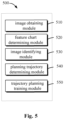
- FIG. 5 illustrates a schematic block diagram of an apparatus 500 for training a trajectory planning model according to some embodiments of the present invention.
- the apparatus 500 may be included in or implemented as computing device 102 of FIG. 1 .
- the apparatus 500 includes an image obtaining module 510 configured to obtain an image of a physical environment in which the vehicle is located by using at least one sensor of the vehicle, the image including a plurality of objects surrounding the vehicle.
- the apparatus 500 further includes a feature chart determining module 520 configured to obtain a feature chart via a trajectory planning model based on the image, the feature chart indicating a plurality of initial trajectory points of the vehicle in the image.
- the apparatus 500 further includes an image identifying module 530 configured to identify the image to determine a first area in the image associated with a road object in the plurality of objects and a second area in the image associated with a non-road object in the plurality of objects.
- the apparatus 500 further includes a planning trajectory determining module 540 configured to determine planning trajectory points based on a positional relationship of the plurality of initial trajectory points with respect to the first area and the second area.
- the apparatus 500 further includes a trajectory planning training module 550 configured to train the trajectory planning model based on the planning trajectory points and actual trajectory points of the vehicle.
- the image identifying module 520 may include: a depth estimation module configured to obtain a depth chart based on a trained depth estimation network, the depth chart indicating a distance of the plurality of objects from the vehicle; and an area determining module configured to determine the first area and the second area based on the distance.
- the planning trajectory determining module 540 may include: a weight determining module configured to determine a corresponding weight of an initial trajectory point of a plurality of initial trajectory points based on a positional relationship; and a trajectory determining module configured to determine a planning trajectory point based on the weight and the feature chart.
- the weight determining module may include a first weight determining module configured to determine that a first set of initial trajectory points has a first weight in response to the first set of initial trajectory points of the plurality of initial trajectory points being within the first area; a second weight determining module configured to determine that a second set of initial trajectory points has a second weight in response to the second set of initial trajectory points of the plurality of initial trajectory points being within the second area; where the first weight is greater than the second weight.
- the first weight may be 1 and the second weight may be 0.4.
- the apparatus 500 may further include a zoom out processing module configured to zoom out the identification chart including the first area and the second area.
- the zoom out processing module includes: a ratio determining module configured to determine a zoom out ratio based on the identification chart in a first predetermined format and the feature chart in a second predetermined format; and a zoom out executing module configured to zoom out the identification chart in the first predetermined format to the identification chart in the second predetermined format based on the zoom out ratio.
- the non-road object includes a pedestrian, a vehicle, a structure, a plant, or a road sign.
- FIG. 6 shows a schematic block diagram of an apparatus 600 for determining a trajectory of a vehicle according to some embodiments of the present invention.
- the apparatus 600 may be included in or implemented as computing device 102 of FIG. 1 .
- the apparatus 600 includes an image determining module 610 configured to obtain an image of a physical environment in which the vehicle is located by using at least one sensor of the vehicle; and a trajectory determining module 620 configured to determine a trajectory of the vehicle through the trajectory planning model based on the image, where the trajectory planning model is trained by the apparatus 500 of FIG. 5 .
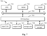
- FIG. 7 illustrates a schematic block diagram of an example device 700 that may be used to implement embodiments of the present invention.
- the computing device 102 in the example environment 100 shown in FIG. 1 may be implemented by a device 700.
- the apparatus 700 includes a central processing unit (CPU) 701, which may perform various appropriate actions and processes according to computer program instructions stored in a Read Only Memory (ROM) 702 or computer program instructions loaded into a Random Access Memory (RAM) 703 from a storage unit 708.
- ROM Read Only Memory
- RAM Random Access Memory
- CPU 701, ROM 702, and RAM 703 are connected to each other via a bus 704.
- An Input/Output (I/O) interface 705 is also connected to bus 704.
- a plurality of components in the device 700 are connected to the I/O interface 705, including an input unit 706, such as a keyboard, a mouse, and the like; An output unit 707, for example, various types of displays, speakers, and the like; A storage unit 708, such as a magnetic disk, an optical disk, or the like; and a communication unit 709, such as a network card, a modem, or a wireless communication transceiver.
- the communication unit 709 allows the device 700 to exchange information/data with other devices over a computer network such as the Internet and/or various telecommunications networks.
- methods 200, 300, and 400 may be performed by processing unit 701.
- methods 200, 300, and 400 may be implemented as a computer software program tangibly embodied in a machine-readable medium, such as storage unit 708.
- some or all of the computer program may be loaded and/or installed on the device 700 via the ROM 702 and/or the communication unit 709.
- the computer program is loaded into the RAM 603 and executed by the CPU 601, one or more actions of the methods 200, 300, and 400 described above may be performed.
- the present invention may be a method, apparatus, system, and/or computer program product.
- the computer program product may include a computer readable storage medium having computer readable program instructions embodied thereon for performing various aspects of the present invention.
- the computer-readable storage medium may be a tangible device that may hold and store instructions for use by the instruction execution device.
- the computer-readable storage medium may be, for example, but not limited to, an electrical storage device, a magnetic storage device, an optical storage device, an electromagnetic storage device, a semiconductor storage device, or any suitable combination of the foregoing.
- the computer-readable storage medium includes: a portable computer disk, a hard disk, a Random Access Memory (RAM), a Read Only Memory (ROM), an Erasable Programmable Read Only Memory (EPROM or flash memory), a Static Random Access Memory (SRAM), a portable Compact Disk Read Only Memory (CD-ROM), a Digital Versatile Disk (DVD), a memory stick, a floppy disk, a mechanical encoding device, e.g., a punch card or in-groove bump structure on which instructions are stored, and any suitable combination of the foregoing.
- RAM Random Access Memory
- ROM Read Only Memory
- EPROM or flash memory Erasable Programmable Read Only Memory
- SRAM Static Random Access Memory
- CD-ROM Compact Disk Read Only Memory
- DVD Digital Versatile Disk
- memory stick e.g., a punch card or in-groove bump structure on which instructions are stored, and any suitable combination of the foregoing.
- a computer-readable storage medium is not to be construed as an instantaneous signal itself, such as a radio wave or other freely propagating electromagnetic wave, an electromagnetic wave propagating through a waveguide or other transmission medium (e.g., an optical pulse through a fiber optic cable), or an electrical signal transmitted through a wire.
- the computer readable program instructions described herein may be downloaded from a computer readable storage medium to various computing/processing devices, or via a network, such as the Internet, a local area network, a wide area network, and/or a wireless network, to an external computer or external storage device.
- the network may include copper transmission cables, fiber optic transmission, wireless transmission, routers, firewalls, switches, gateway computers, and/or edge servers.
- a network adapter card or network interface in each computing/processing device receives computer readable program instructions from the network and forwards the computer readable program instructions for storage in a computer readable storage medium in the respective computing/processing device.
- the computer program instructions used to perform the operations of the present invention may be assembly instructions, Instruction Set Architecture (ISA) instructions, machine instructions, machine-related instructions, microcode, firmware instructions, state setting data, or source or object code written in any combination of one or more programming languages, including object-oriented programming languages such as Smalltalk, C + +, and the like, and conventional procedural programming languages such as "C" language and similar coding language.
- ISA Instruction Set Architecture
- the computer readable program instructions may be executed entirely on the user computer, partly on the user computer, as a separate software package, partly on the user computer and partly on the remote computer, or entirely on the remote computer or server.
- the remote computer may be connected to the user computer through any kind of network, including a Local Area Network (LAN) or a Wide Area Network (WAN), or may be connected to an external computer (e.g., connected through the Internet using an Internet service provider).
- electronic circuits such as programmable logic circuits, Field Programmable Gate Arrays (FPGAs), or Programmable Logic Arrays (PLAs), can be personalized with the status information of the computer-readable program instructions, which can execute the computer-readable program instructions to implement various aspects of the present invention.
- the computer readable program instructions may be provided to a processing unit of a general purpose computer, special purpose computer, or other programmable data processing apparatus to produce a machine such that the instructions, when executed by the processing unit of the computer or other programmable data processing apparatus, produce means for implementing the functions/actions specified in one or more blocks of the flowchart and/or block diagram.
- the computer-readable program instructions may also be stored in a computer-readable storage medium that cause a computer, programmable data processing apparatus, and/or other device to operate in a particular manner, such that the computer-readable medium having the instructions stored thereon includes an article of manufacture that includes instructions that implement various aspects of the functions/actions specified in one or more blocks of the flowchart and/or block diagram.
- Computer readable program instructions may also be loaded onto a computer, other programmable data processing apparatus, or other device such that a series of operational steps are performed on the computer, other programmable data processing apparatus, or other device to produce a computer-implemented process such that the instructions that execute on the computer, other programmable data processing apparatus, or other device implement the functions/actions specified in one or more blocks of the flowcharts and/or block diagrams.
- each block in a flowchart or block diagram may represent a module, program segment, or portion of an instruction that contains one or more executable instructions for implementing a specified logical function.
- the functions noted in the blocks may also occur in an order different from that noted in the drawings. For example, two successive blocks may actually be executed substantially in parallel, and they may sometimes be executed in the reverse order, depending on the functionality involved.
- each block of the block diagrams and/or flowcharts, and combinations of blocks in the block diagrams and/or flowcharts may be implemented with a dedicated hardware-based system that performs the specified functions or actions, or may be implemented with a combination of dedicated hardware and computer instructions.
Claims (14)
- Verfahren zum Trainieren eines Trajektorienplanungsmodells, wobei das Trajektorienplanungsmodell ein neuronales Netzwerkmodell ist, wobei das Verfahren Folgendes umfasst:Erhalten (210), mithilfe mindestens eines Sensors eines Fahrzeugs, eines Bilds einer physischen Umgebung, in der sich das Fahrzeug befindet, wobei das erhaltene Bild mehrere Objekte umfasst, die das Fahrzeug umgeben;Eingeben des Bilds in das Trajektorienplanungsmodell und Erhalten (220) eines Merkmalsdiagramms aus dem Trajektorienplanungsmodell basierend auf dem Bild, wobei das erhaltene Bild durch das Trajektorienplanungsmodell verarbeitet wird, um eine geplante Trajektorie des Fahrzeugs zu bestimmen, wobei das Merkmalsdiagramm mehrere anfängliche Trajektorienpunkte des Fahrzeugs in dem Bild angibt;Identifizieren (230) des Bilds, um in dem Bild einen ersten Bereich, der einem Straßenobjekt in den mehreren Objekten zugeordnet ist, und einen zweiten Bereich, der einem Nicht-Straßenobjekt in den mehreren Objekten zugeordnet ist, zu bestimmen;Bestimmen (240) von Planungstrajektorienpunkten basierend auf einer Positionsbeziehung der mehreren anfänglichen Trajektorienpunkte in Bezug auf den ersten Bereich und den zweiten Bereich, wobei das Bestimmen (240) der Planungstrajektorienpunkte Folgendes umfasst:Bestimmen (310) von Gewichtungen für die anfänglichen Trajektorienpunkte basierend auf der Positionsbeziehung, wobei ein erster Satz der anfänglichen Trajektorienpunkte, die zu dem ersten Bereich gehören, eingestellt ist, um eine erste Gewichtung aufzuweisen, und ein zweiter Satz der anfänglichen Trajektorienpunkte, die zu dem zweiten Bereich gehören, eingestellt ist, um eine zweite Gewichtung aufzuweisen, die kleiner als die erste Gewichtung ist;Bestimmen (320) der Planungstrajektorienpunkte basierend auf der Gewichtung und auf dem Merkmalsdiagramm durch Punktmultiplizieren einer Matrix, die dem Merkmalsdiagramm entspricht, und einer Matrix einer Gewichtungsmatrix, die den Gewichtungen entspricht; undBestimmen der Planungstrajektorienpunkte durch eine transponierte Faltungs- und Sigmoidaktivierungsschicht; undTrainieren (250) des Trajektorienplanungsmodells durch Vergleichen der Planungstrajektorienpunkte mit tatsächlichen Trajektorienpunkten des Fahrzeugs.
- Verfahren nach Anspruch 1, wobei das Bestimmen des ersten Bereichs und des zweiten Bereichs Folgendes umfasst:
Erhalten eines Tiefendiagramms über ein trainiertes Tiefenschätzungsnetzwerk, wobei das Tiefendiagramm einen Abstand der mehreren Objekte von dem Fahrzeug angibt; und Bestimmen des ersten Bereichs und des zweiten Bereichs basierend auf dem erhaltenen Abstand. - Verfahren nach Anspruch 1 oder 2, wobei das Bestimmen der Gewichtungen Folgendes umfasst:Bestimmen, dass ein erster Satz von anfänglichen Trajektorienpunkten der mehreren anfänglichen Trajektorienpunkte eine erste Gewichtung aufweist, als Reaktion darauf, dass sich der erste Satz von anfänglichen Trajektorienpunkten in dem ersten Bereich befindet; Bestimmen, dass ein zweiter Satz von anfänglichen Trajektorienpunkten der mehreren anfänglichen Trajektorienpunkte eine zweite Gewichtung aufweist, als Reaktion darauf, dass sich der zweite Satz von anfänglichen Trajektorienpunkten in dem zweiten Bereich befindet;wobei die erste Gewichtung größer als die zweite Gewichtung ist.
- Verfahren nach Anspruch 3, wobei die erste Gewichtung 1 ist und die zweite Gewichtung 0,4 ist.
- Verfahren nach einem der Ansprüche 1 bis 4, wobei das Verfahren ferner Folgendes umfasst:
Durchführen eines Herauszoomprozesses an einem Identifikationsdiagramm, das den ersten Bereich und den zweiten Bereich beinhaltet, umfassend:Bestimmen eines Herauszoomverhältnisses basierend auf dem Identifikationsdiagramm in einem ersten vorbestimmten Format und dem Merkmalsdiagramm in einem zweiten vorbestimmten Format; undHerauszoomen des Identifikationsdiagramms in dem ersten vorbestimmten Format, um das Identifikationsdiagramm in dem zweiten vorbestimmten Format zu sein, basierend auf dem Herauszoomverhältnis. - Verfahren nach einem der Ansprüche 1 bis 5, wobei das Nicht-Straßenobjekt einen Fußgänger, ein Fahrzeug, eine Struktur, eine Pflanze oder ein Straßenschild umfasst.
- Verfahren zum Bestimmen einer Trajektorie eines Fahrzeugs, die Folgendes umfasst:Erhalten (410), mithilfe mindestens eines Sensors eines Fahrzeugs, eines Bilds einer physischen Umgebung, in der sich das Fahrzeug befindet; undBestimmen (420) einer Traj ektorie des Fahrzeugs durch Eingeben des Bilds in ein Trajektorienplanungsmodell basierend auf dem erhaltenen Bild, wobei das erhaltene Bild durch das Trajektorienplanungsmodell verarbeitet wird, um die Trajektorie des Fahrzeugs zu bestimmen, wobei das Trajektorienplanungsmodell gemäß dem Verfahren der Ansprüche 1 bis 6 trainiert wird.
- Vorrichtung zum Trainieren eines Trajektorienplanungsmodells, die Folgendes umfasst:
Module zum Durchführen des Verfahrens nach einem der Ansprüche 1 bis 7. - Vorrichtung zum Bestimmen einer Trajektorie eines Fahrzeugs, umfassend:ein Bildbestimmungsmodul, das konfiguriert ist, um mithilfe mindestens eines Sensors eines Fahrzeugs ein Bild einer physischen Umgebung zu erhalten, in der sich das Fahrzeug befindet; undein Trajektorienbestimmungsmodul, das dazu konfiguriert ist, eine Trajektorie des Fahrzeugs durch ein Trajektorienplanungsmodell basierend auf dem Bild zu bestimmen, wobei das Trajektorienplanungsmodell gemäß der Vorrichtung nach Anspruch 8 trainiert wird.
- Elektronische Vorrichtung, die Folgendes umfasst:einen oder mehrere Prozessoren; undeine Speichervorrichtung zum Speichern eines oder mehrerer Programme, die bei Ausführung durch den einen oder die mehreren Prozessoren bewirken, dass der eine oder die mehreren Prozessoren das Verfahren nach einem der Ansprüche 1 bis 6 implementieren.
- Elektronische Vorrichtung, umfassend:einen oder mehrere Prozessoren; undeine Speichervorrichtung zum Speichern eines oder mehrerer Programme, die bei Ausführung durch den einen oder die mehreren Prozessoren bewirken, dass der eine oder die mehreren Prozessoren das Verfahren nach Anspruch 7 implementieren.
- Computerlesbares Speichermedium, auf dem ein Computerprogramm gespeichert ist, das bei Ausführung durch einen Prozessor das Verfahren nach einem der Ansprüche 1 bis 6 implementiert.
- Computerlesbares Speichermedium, auf dem ein Computerprogramm gespeichert ist, das bei Ausführung durch einen Prozessor das Verfahren nach Anspruch 7 implementiert.
- Computerprogramm, umfassend Anweisungen, die bei Ausführung des Programms durch einen Computer bewirken, dass der Computer das Verfahren nach einem der Ansprüche 1 bis 6 oder das Verfahren nach Anspruch 7 durchführt.
Applications Claiming Priority (1)
| Application Number | Priority Date | Filing Date | Title |
|---|---|---|---|
| CN202010623703.5A CN111860227B (zh) | 2020-06-30 | 2020-06-30 | 训练轨迹规划模型的方法、装置和计算机存储介质 |
Publications (3)
| Publication Number | Publication Date |
|---|---|
| EP3822852A2 EP3822852A2 (de) | 2021-05-19 |
| EP3822852A3 EP3822852A3 (de) | 2021-11-03 |
| EP3822852B1 true EP3822852B1 (de) | 2023-10-11 |
Family
ID=72988920
Family Applications (1)
| Application Number | Title | Priority Date | Filing Date |
|---|---|---|---|
| EP21166377.8A Active EP3822852B1 (de) | 2020-06-30 | 2021-03-31 | Verfahren, vorrichtung, computerprogrammprodukt und computerlesbarer datenträger zum trainieren eines routenplannungsmodells |
Country Status (5)
| Country | Link |
|---|---|
| US (1) | US11940803B2 (de) |
| EP (1) | EP3822852B1 (de) |
| JP (1) | JP7245275B2 (de) |
| KR (1) | KR102539942B1 (de) |
| CN (1) | CN111860227B (de) |
Families Citing this family (9)
| Publication number | Priority date | Publication date | Assignee | Title |
|---|---|---|---|---|
| CN112556701A (zh) * | 2020-12-23 | 2021-03-26 | 北京嘀嘀无限科技发展有限公司 | 用于定位交通工具的方法、装置、设备和存储介质 |
| CN112785072B (zh) * | 2021-01-29 | 2024-04-12 | 北京百度网讯科技有限公司 | 路线规划和模型训练方法、装置、设备及存储介质 |
| CN113031600B (zh) * | 2021-03-02 | 2023-09-05 | 京东鲲鹏(江苏)科技有限公司 | 一种轨迹生成方法、装置、存储介质及电子设备 |
| DE102021112119A1 (de) * | 2021-05-10 | 2022-11-10 | Dr. Ing. H.C. F. Porsche Aktiengesellschaft | Verfahren und Vorrichtung zur Trajektorienplanung für ein Fahrzeug |
| CN113506604B (zh) * | 2021-08-19 | 2022-07-12 | 遨博(北京)智能科技有限公司 | 一种按摩轨迹调整方法 |
| CN114047764B (zh) * | 2021-11-16 | 2023-11-07 | 北京百度网讯科技有限公司 | 路径规划模型的训练方法和路径规划方法、装置 |
| GB2619923A (en) * | 2022-06-20 | 2023-12-27 | Oxa Autonomy Ltd | A computer-implemented method of determining a trajectory of an autonomous vehicle |
| CN115018182B (zh) * | 2022-06-28 | 2024-02-09 | 广东电网有限责任公司 | 一种通信电路的规划管理方法、装置、存储介质以及系统 |
| CN116777947B (zh) * | 2023-06-21 | 2024-02-13 | 上海汉朔信息科技有限公司 | 一种用户轨迹识别预测方法、装置及电子设备 |
Family Cites Families (22)
| Publication number | Priority date | Publication date | Assignee | Title |
|---|---|---|---|---|
| JP6788477B2 (ja) * | 2016-03-10 | 2020-11-25 | パナソニック インテレクチュアル プロパティ コーポレーション オブ アメリカPanasonic Intellectual Property Corporation of America | 認識結果提示装置及び認識結果提示方法 |
| EP3709271B1 (de) * | 2016-09-15 | 2022-11-02 | Google LLC | Neuronale netzwerke zur bildtiefenvorhersage |
| WO2018232681A1 (en) * | 2017-06-22 | 2018-12-27 | Baidu.Com Times Technology (Beijing) Co., Ltd. | TRAFFIC PREDICTION BASED ON CARD IMAGES FOR AUTONOMOUS DRIVING |
| US10007269B1 (en) * | 2017-06-23 | 2018-06-26 | Uber Technologies, Inc. | Collision-avoidance system for autonomous-capable vehicle |
| US11256983B2 (en) * | 2017-07-27 | 2022-02-22 | Waymo Llc | Neural networks for vehicle trajectory planning |
| US10883844B2 (en) * | 2017-07-27 | 2021-01-05 | Waymo Llc | Neural networks for vehicle trajectory planning |
| EP3523753A4 (de) * | 2017-12-11 | 2019-10-23 | Beijing Didi Infinity Technology and Development Co., Ltd. | Systeme und verfahren zur identifizierung und positionieren von objekten in der umgebung eines fahrzeugs |
| US11128854B2 (en) * | 2018-03-13 | 2021-09-21 | Magic Leap, Inc. | Image-enhanced depth sensing via depth sensor control |
| US11860640B2 (en) * | 2018-03-29 | 2024-01-02 | Sony Corporation | Signal processing device and signal processing method, program, and mobile body |
| US10816992B2 (en) | 2018-04-17 | 2020-10-27 | Baidu Usa Llc | Method for transforming 2D bounding boxes of objects into 3D positions for autonomous driving vehicles (ADVs) |
| EP3803828B1 (de) | 2018-05-31 | 2022-03-30 | Nissan North America, Inc. | Probabilistisches objektverfolgungs- und prädiktionsframework |
| US11740630B2 (en) * | 2018-06-12 | 2023-08-29 | Skydio, Inc. | Fitness and sports applications for an autonomous unmanned aerial vehicle |
| US11675359B2 (en) | 2018-06-13 | 2023-06-13 | Nvidia Corporation | Path detection for autonomous machines using deep neural networks |
| US11966838B2 (en) | 2018-06-19 | 2024-04-23 | Nvidia Corporation | Behavior-guided path planning in autonomous machine applications |
| CN112714913A (zh) * | 2018-09-26 | 2021-04-27 | 法弗人工智能有限公司 | 结构注释 |
| US11077878B2 (en) * | 2018-11-02 | 2021-08-03 | Zoox, Inc. | Dynamic lane biasing |
| CN109606384B (zh) * | 2018-12-29 | 2021-04-20 | 百度在线网络技术(北京)有限公司 | 车辆控制方法、装置、设备和存储介质 |
| CN110083160B (zh) * | 2019-05-16 | 2022-04-19 | 哈尔滨工业大学(深圳) | 一种基于深度学习的机器人轨迹规划方法 |
| KR20200133863A (ko) * | 2019-05-20 | 2020-12-01 | 삼성전자주식회사 | 첨단 운전자 지원 장치, 이의 캘리브레이션 방법 및 이의 객체를 검출하는 방법 |
| US11227187B1 (en) * | 2019-05-23 | 2022-01-18 | Augustus Intelligence Inc. | Generating artificial intelligence solutions using raw data and simulated data |
| US11625839B2 (en) * | 2020-05-18 | 2023-04-11 | Toyota Research Institute, Inc. | Bird's eye view based velocity estimation via self-supervised learning |
| US11402840B2 (en) * | 2020-06-30 | 2022-08-02 | Woven Planet North America, Inc. | Independent trajectory validation system for vehicles |
-
2020
- 2020-06-30 CN CN202010623703.5A patent/CN111860227B/zh active Active
-
2021
- 2021-03-25 JP JP2021051797A patent/JP7245275B2/ja active Active
- 2021-03-29 US US17/216,208 patent/US11940803B2/en active Active
- 2021-03-31 EP EP21166377.8A patent/EP3822852B1/de active Active
- 2021-03-31 KR KR1020210042199A patent/KR102539942B1/ko active IP Right Grant
Also Published As
| Publication number | Publication date |
|---|---|
| EP3822852A3 (de) | 2021-11-03 |
| EP3822852A2 (de) | 2021-05-19 |
| KR20210043516A (ko) | 2021-04-21 |
| US20210216077A1 (en) | 2021-07-15 |
| CN111860227A (zh) | 2020-10-30 |
| JP2022003508A (ja) | 2022-01-11 |
| CN111860227B (zh) | 2024-03-08 |
| US11940803B2 (en) | 2024-03-26 |
| JP7245275B2 (ja) | 2023-03-23 |
| KR102539942B1 (ko) | 2023-06-02 |
Similar Documents
| Publication | Publication Date | Title |
|---|---|---|
| EP3822852B1 (de) | Verfahren, vorrichtung, computerprogrammprodukt und computerlesbarer datenträger zum trainieren eines routenplannungsmodells | |
| US11276230B2 (en) | Inferring locations of 3D objects in a spatial environment | |
| US20240144010A1 (en) | Object Detection and Property Determination for Autonomous Vehicles | |
| US11221413B2 (en) | Three-dimensional object detection | |
| US10817752B2 (en) | Virtually boosted training | |
| JP7239703B2 (ja) | 領域外コンテキストを用いたオブジェクト分類 | |
| US11772654B2 (en) | Occupancy prediction neural networks | |
| EP4152204A1 (de) | Fahrspurliniendetektionsverfahren und zugehörige vorrichtung | |
| KR20200096131A (ko) | 다양한 소스로부터 획득되는 정보의 퓨전을 통해 주변 객체의 모션을 예측함으로써, 사고 위험을 회피하여 안전한 자율 주행을 지원하는 학습 방법, 그리고 이를 이용한 학습 장치, 테스트 방법, 및 테스트 장치 | |
| WO2021226921A1 (en) | Method and system of data processing for autonomous driving | |
| CN113348422A (zh) | 用于生成预测占据栅格地图的方法和系统 | |
| US11966234B2 (en) | System and method for monocular depth estimation from semantic information | |
| EP3640846B1 (de) | Verfahren und vorrichtung zum trainieren eines bilderkennungsmodells sowie bilderkennungsverfahren und -vorrichtung | |
| US20230213643A1 (en) | Camera-radar sensor fusion using local attention mechanism | |
| US20210312177A1 (en) | Behavior prediction of surrounding agents | |
| CN114882457A (zh) | 一种模型的训练方法、车道线的检测方法及设备 | |
| US20210398014A1 (en) | Reinforcement learning based control of imitative policies for autonomous driving | |
| US20220237402A1 (en) | Static occupancy tracking | |
| CN114889608A (zh) | 一种基于注意力机制的车辆换道预测方法 | |
| US11544899B2 (en) | System and method for generating terrain maps | |
| CN114407916B (zh) | 车辆控制及模型训练方法、装置、车辆、设备和存储介质 | |
| Zhang et al. | PilotAttnNet: Multi-modal Attention Network for End-to-End Steering Control | |
| WO2022159331A1 (en) | Static occupancy tracking | |
| CN116300928A (zh) | 针对车辆的数据处理方法和数据处理模型的训练方法 | |
| CN116880462A (zh) | 自动驾驶模型、训练方法和自动驾驶方法和车辆 |
Legal Events
| Date | Code | Title | Description |
|---|---|---|---|
| PUAI | Public reference made under article 153(3) epc to a published international application that has entered the european phase |
Free format text: ORIGINAL CODE: 0009012 |
|
| STAA | Information on the status of an ep patent application or granted ep patent |
Free format text: STATUS: REQUEST FOR EXAMINATION WAS MADE |
|
| 17P | Request for examination filed |
Effective date: 20210331 |
|
| AK | Designated contracting states |
Kind code of ref document: A2 Designated state(s): AL AT BE BG CH CY CZ DE DK EE ES FI FR GB GR HR HU IE IS IT LI LT LU LV MC MK MT NL NO PL PT RO RS SE SI SK SM TR |
|
| PUAL | Search report despatched |
Free format text: ORIGINAL CODE: 0009013 |
|
| AK | Designated contracting states |
Kind code of ref document: A3 Designated state(s): AL AT BE BG CH CY CZ DE DK EE ES FI FR GB GR HR HU IE IS IT LI LT LU LV MC MK MT NL NO PL PT RO RS SE SI SK SM TR |
|
| RIC1 | Information provided on ipc code assigned before grant |
Ipc: G06K 9/00 20060101AFI20210924BHEP |
|
| REG | Reference to a national code |
Ref country code: DE Ref legal event code: R079 Ref document number: 602021005728 Country of ref document: DE Free format text: PREVIOUS MAIN CLASS: G06K0009000000 Ipc: G06V0020560000 Ref country code: DE Ref legal event code: R079 Free format text: PREVIOUS MAIN CLASS: G06K0009000000 Ipc: G06V0020560000 |
|
| GRAP | Despatch of communication of intention to grant a patent |
Free format text: ORIGINAL CODE: EPIDOSNIGR1 |
|
| STAA | Information on the status of an ep patent application or granted ep patent |
Free format text: STATUS: GRANT OF PATENT IS INTENDED |
|
| RIC1 | Information provided on ipc code assigned before grant |
Ipc: G06N 3/045 20230101ALI20230614BHEP Ipc: G06N 3/08 20060101ALI20230614BHEP Ipc: G06V 10/82 20220101ALI20230614BHEP Ipc: G01C 21/34 20060101ALI20230614BHEP Ipc: G06V 20/56 20220101AFI20230614BHEP |
|
| INTG | Intention to grant announced |
Effective date: 20230628 |
|
| GRAS | Grant fee paid |
Free format text: ORIGINAL CODE: EPIDOSNIGR3 |
|
| GRAA | (expected) grant |
Free format text: ORIGINAL CODE: 0009210 |
|
| STAA | Information on the status of an ep patent application or granted ep patent |
Free format text: STATUS: THE PATENT HAS BEEN GRANTED |
|
| AK | Designated contracting states |
Kind code of ref document: B1 Designated state(s): AL AT BE BG CH CY CZ DE DK EE ES FI FR GB GR HR HU IE IS IT LI LT LU LV MC MK MT NL NO PL PT RO RS SE SI SK SM TR |
|
| REG | Reference to a national code |
Ref country code: GB Ref legal event code: FG4D |
|
| REG | Reference to a national code |
Ref country code: CH Ref legal event code: EP |
|
| REG | Reference to a national code |
Ref country code: DE Ref legal event code: R096 Ref document number: 602021005728 Country of ref document: DE |
|
| REG | Reference to a national code |
Ref country code: IE Ref legal event code: FG4D |
|
| P01 | Opt-out of the competence of the unified patent court (upc) registered |
Effective date: 20231117 |
|
| REG | Reference to a national code |
Ref country code: LT Ref legal event code: MG9D |
|
| REG | Reference to a national code |
Ref country code: NL Ref legal event code: MP Effective date: 20231011 |
|
| REG | Reference to a national code |
Ref country code: AT Ref legal event code: MK05 Ref document number: 1620994 Country of ref document: AT Kind code of ref document: T Effective date: 20231011 |
|
| PG25 | Lapsed in a contracting state [announced via postgrant information from national office to epo] |
Ref country code: NL Free format text: LAPSE BECAUSE OF FAILURE TO SUBMIT A TRANSLATION OF THE DESCRIPTION OR TO PAY THE FEE WITHIN THE PRESCRIBED TIME-LIMIT Effective date: 20231011 |
|
| PG25 | Lapsed in a contracting state [announced via postgrant information from national office to epo] |
Ref country code: GR Free format text: LAPSE BECAUSE OF FAILURE TO SUBMIT A TRANSLATION OF THE DESCRIPTION OR TO PAY THE FEE WITHIN THE PRESCRIBED TIME-LIMIT Effective date: 20240112 |
|
| PG25 | Lapsed in a contracting state [announced via postgrant information from national office to epo] |
Ref country code: IS Free format text: LAPSE BECAUSE OF FAILURE TO SUBMIT A TRANSLATION OF THE DESCRIPTION OR TO PAY THE FEE WITHIN THE PRESCRIBED TIME-LIMIT Effective date: 20240211 |
|
| PG25 | Lapsed in a contracting state [announced via postgrant information from national office to epo] |
Ref country code: LT Free format text: LAPSE BECAUSE OF FAILURE TO SUBMIT A TRANSLATION OF THE DESCRIPTION OR TO PAY THE FEE WITHIN THE PRESCRIBED TIME-LIMIT Effective date: 20231011 |
|
| PG25 | Lapsed in a contracting state [announced via postgrant information from national office to epo] |
Ref country code: AT Free format text: LAPSE BECAUSE OF FAILURE TO SUBMIT A TRANSLATION OF THE DESCRIPTION OR TO PAY THE FEE WITHIN THE PRESCRIBED TIME-LIMIT Effective date: 20231011 |
|
| PG25 | Lapsed in a contracting state [announced via postgrant information from national office to epo] |
Ref country code: ES Free format text: LAPSE BECAUSE OF FAILURE TO SUBMIT A TRANSLATION OF THE DESCRIPTION OR TO PAY THE FEE WITHIN THE PRESCRIBED TIME-LIMIT Effective date: 20231011 |
|
| PG25 | Lapsed in a contracting state [announced via postgrant information from national office to epo] |
Ref country code: LT Free format text: LAPSE BECAUSE OF FAILURE TO SUBMIT A TRANSLATION OF THE DESCRIPTION OR TO PAY THE FEE WITHIN THE PRESCRIBED TIME-LIMIT Effective date: 20231011 Ref country code: IS Free format text: LAPSE BECAUSE OF FAILURE TO SUBMIT A TRANSLATION OF THE DESCRIPTION OR TO PAY THE FEE WITHIN THE PRESCRIBED TIME-LIMIT Effective date: 20240211 Ref country code: GR Free format text: LAPSE BECAUSE OF FAILURE TO SUBMIT A TRANSLATION OF THE DESCRIPTION OR TO PAY THE FEE WITHIN THE PRESCRIBED TIME-LIMIT Effective date: 20240112 Ref country code: ES Free format text: LAPSE BECAUSE OF FAILURE TO SUBMIT A TRANSLATION OF THE DESCRIPTION OR TO PAY THE FEE WITHIN THE PRESCRIBED TIME-LIMIT Effective date: 20231011 Ref country code: BG Free format text: LAPSE BECAUSE OF FAILURE TO SUBMIT A TRANSLATION OF THE DESCRIPTION OR TO PAY THE FEE WITHIN THE PRESCRIBED TIME-LIMIT Effective date: 20240111 Ref country code: AT Free format text: LAPSE BECAUSE OF FAILURE TO SUBMIT A TRANSLATION OF THE DESCRIPTION OR TO PAY THE FEE WITHIN THE PRESCRIBED TIME-LIMIT Effective date: 20231011 Ref country code: PT Free format text: LAPSE BECAUSE OF FAILURE TO SUBMIT A TRANSLATION OF THE DESCRIPTION OR TO PAY THE FEE WITHIN THE PRESCRIBED TIME-LIMIT Effective date: 20240212 |