EP3822719A1 - Program development device and controller - Google Patents
Program development device and controller Download PDFInfo
- Publication number
- EP3822719A1 EP3822719A1 EP19834953.2A EP19834953A EP3822719A1 EP 3822719 A1 EP3822719 A1 EP 3822719A1 EP 19834953 A EP19834953 A EP 19834953A EP 3822719 A1 EP3822719 A1 EP 3822719A1
- Authority
- EP
- European Patent Office
- Prior art keywords
- motion control
- control command
- command
- user
- program
- Prior art date
- Legal status (The legal status is an assumption and is not a legal conclusion. Google has not performed a legal analysis and makes no representation as to the accuracy of the status listed.)
- Granted
Links
Images




Classifications
-
- G—PHYSICS
- G05—CONTROLLING; REGULATING
- G05B—CONTROL OR REGULATING SYSTEMS IN GENERAL; FUNCTIONAL ELEMENTS OF SUCH SYSTEMS; MONITORING OR TESTING ARRANGEMENTS FOR SUCH SYSTEMS OR ELEMENTS
- G05B19/00—Program-control systems
- G05B19/02—Program-control systems electric
- G05B19/04—Program control other than numerical control, i.e. in sequence controllers or logic controllers
- G05B19/042—Program control other than numerical control, i.e. in sequence controllers or logic controllers using digital processors
- G05B19/0426—Programming the control sequence
-
- G—PHYSICS
- G06—COMPUTING OR CALCULATING; COUNTING
- G06F—ELECTRIC DIGITAL DATA PROCESSING
- G06F8/00—Arrangements for software engineering
- G06F8/30—Creation or generation of source code
- G06F8/36—Software reuse
Definitions
- the invention relates to a program development device and a controller.
- the command words (individual codes in the program source) used for motion control of machines such as PLCs (Programmable Logic Controllers), machine tools, and robots may be standardized or systematized respectively for use.
- a code conforming to IEC61131-3 JIS B 3503 is, for example, a command word for PLC.
- a G code used in CNC is also standardized by ISO and can be used as a command word.
- PLCs and machine tools have a configuration that does not allow the user to change the processing content of a command word or add a new command word in order to guarantee the operation.
- the user could create a library of a user program using the command words provided by the manufacturer.
- the library is a user program written in IEC61131-3 that is made into a component in the form of a function block or a function, and can improve the reusability of the program or conceal the user program.
- the command words provided by the manufacturer may have functional restrictions in order to guarantee the operation, so the functions that can be realized with the library, which is a combination of command words, are limited, and the user cannot make changes as desired.
- One aspect of the invention has been made in view of the above circumstances, and one aspect of the invention is to provide a technique that allows the user to change the processing content of a command word used for the motion control of a machine and add a new command word, thereby realizing a new function not defined by the manufacturer.
- a program development device for creating a user program operating on a controller that controls motion of a machine.
- the program development device includes a first storage unit that stores a default first motion control command in association with a command word; and an editing unit that edits a motion control command corresponding to the command word according to an instruction of a user.
- a controller for controlling motion of a machine according to a user program.
- the controller includes an execution unit that executes the user program; a first command library that stores an execution code of a default first motion control command corresponding to a command word; and a second command library that stores an execution code of a second motion control command, which is defined by a user, corresponding to the command word.
- the execution unit decides whether to call the execution code of the first motion control command or the execution code of the second motion control command according to the user program.
- the user can change the processing content of a command word used for the motion control of a machine and add a new command word.
- FIG. 1 is a diagram showing an outline of a system environment in which a program development device 5 and a controller 1 according to the present embodiment are used.
- the controller 1 controls the motion of a machine connected via a motion network cable 2.
- the controller 1 is, for example, a PLC, a machine tool controller, a robot controller, or the like.
- the controller 1 is connected to a servo driver 200 via the motion network cable 2 and drives a servo motor 201 connected to the servo driver 200.
- EtherCAT registered trademark
- EtherCAT registered trademark
- the program development device 5 has a function of editing a user program and a command word according to a user operation. Further, the program development device 5 checks the codes of the edited command word and determines whether the machine to be controlled by the controller 1 operates normally. In addition, the program development device 5 builds the edited user program and command word, converts them into an executable file format, and then transfers and saves them in the controller 1.
- the user can change the processing content of the command word and add a new command word by operating the program development device 5.
- the user can set the processing content that the user wants to realize in the command word in an interactive manner with the program development device 5.
- the program development device 5 generates the processing content set by the user in a high-level language such as C or C++.
- the user can also program the processing content that the user wants to realize in the command word in a high-level language such as C or C++.
- the user program and command word edited by the user are generated after the simulation confirms that a call error of the API of the controller firmware does not occur.
- the API of the controller firmware can be executed only when the firmware is on standby, it has a configuration that retains the firmware state, accepts API processing when it is in an acceptable state, and returns an error when it is in an unacceptable state. Therefore, the firmware is prevented from entering an unauthorized state.
- the user can change the processing content of the command word used for the motion control of the machine and add a new command word.
- the program development device 5 can implement the edited user program and command word on the controller 1 after it is confirmed that the motion control of the machine is normally performed by using the API of the controller firmware.
- FIG. 1 is a diagram showing the outline of the system environment in which the program development device 5 and the controller 1 are used.
- FIG. 2 is a block diagram showing a main configuration of the controller 1.
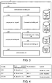
- FIG. 3 is a block diagram showing a main configuration of the program development device 5.
- the controller 1 is connected to the servo driver 200 of the machine tool to be controlled via the motion network cable 2 and drives the servo motor 201 connected to the servo driver 200.
- the machine tool to be controlled by the controller 1 includes a plurality of servo drivers 200, and by driving the servo motors 201 respectively connected to the servo drivers 200, machines a machining target part.
- FIG. 1 shows a configuration in which the controller 1 controls the motion of the machine tool, the controller 1 is not limited to a controller of a machine tool, and may be a PLC or a robot controller.
- a communication coupler 202 can be connected to the controller 1 via the motion network cable 2.
- FIG. 1 shows an example in which the connection is realized by a daisy chain method, the servo drivers 200 and the communication coupler 202 may be connected by other connection methods.
- a general-purpose analog output unit 205, a general-purpose analog input unit 204, and a general-purpose digital input/output unit 203 can exchange data with the communication coupler 202 via an internal bus.
- a touch panel 4 is connected to the controller 1 via a network HUB 3.
- the touch panel 4 is an operation panel of the controller 1.
- the touch panel 4 may be attached to the machine tool or robot to be controlled, or may be provided separately from the machine tool or robot to be controlled.
- the program development device 5 is connected to the controller 1 by an Ethernet (registered trademark) cable 301 via the network HUB 3.
- the program development device 5 is, for example, a general-purpose computer.
- the program development device 5 stores the user program executed by the controller 1 and the command word used for the motion control of the machine tool by the controller 1. Although details will be described later, the user can edit the user program and the command word to be executed in the controller 1 by operating the program development device 5.
- the controller 1 includes an interface 607 (communication unit) that transmits and receives data to and from the program development device 5, and is connected to the program development device 5 via the interface 607.
- the controller 1 includes a motion network unit 608 that is an interface for transmitting and receiving data to and from the servo driver 200.
- the motion network unit 608 communicates with the servo driver 200 via a motion network port 101.
- the controller 1 includes a storage unit 610 and an execution unit 620.
- the controller 1 includes a firmware API (application program interface) 602, firmware 603, an operating system (OS) 604, and a device driver 605.
- firmware API application program interface
- OS operating system
- the storage unit 610 stores a user program 606, a manufacturer-defined command word group 600, and a user-defined command word group 601.
- Each of the user program 606, the manufacturer-defined command word group 600, and the user-defined command word group 601 stores a program written in codes conforming to IEC61131-3 when the controller 1 is a PLC, and a program written in G codes standardized by ISO when the controller 1 is a motion controller of a machine tool.
- the user program 606 is a program executed on the controller 1 and is a program that controls the operation of the controller 1. In other words, the controller 1 controls the motion of the machine to be controlled according to the user program.
- the controller 1 When the controller 1 is a PLC, the user program 606 is built and stored in the storage unit 610 in a binary format. When the controller 1 is a controller of a machine tool, the CNC user program is not built, and the source code written in G codes is stored in the storage unit 610 in a text format.
- the manufacturer-defined command word group 600 includes a plurality of command words, and default processing contents which are realized by the command words and associated with the respective command words.
- the default processing content refers to the content of processing associated with each command word, which is defined by the manufacturer that manufactures the controller 1, and is, for example, the content of processing according to the G codes conforming to the ISO standard.
- the control command for executing the default processing, which corresponds to the command word, is referred to as a first motion control command.
- the manufacturer-defined command word group 600 includes a library, which is an execution code of the first motion control command, in a built binary format in association with each command word.
- the area for storing the manufacturer-defined command word group 600 is also referred to as a first command library.
- the user-defined command word group 601 includes a plurality of command words, and processing contents defined by the user, which are realized by the command words and associated with the respective command words.
- the control command for executing the user-defined processing, which corresponds to the command word, is referred to as a second motion control command.
- the user-defined command word group 601 includes a user-defined command word, which is an execution code of the second motion control command, in a built binary format in association with each command word.
- the area for storing the user-defined command word group 601 is also referred to as a second command library.
- the execution unit 620 loads and executes the user program and the command library stored in the storage unit 610.
- the execution unit 620 may be composed of, for example, a CPU as an arithmetic device and a memory.
- the execution unit 620 decides whether to call the default command word stored in the manufacturer-defined command word group 600 or the user-defined command word stored in the user-defined command word group 601 according to the user program.
- the controller 1 is a PLC and the user program is a compiler type program
- the user program writes whether to call the execution code of the first motion control command or the execution code of the second motion control command.
- the execution unit 620 can decide whether to call the execution code existing in the first command library or call the execution code existing in the second command library.
- the execution unit 620 reads the source file of the user program line by line and executes the commands of each line in order. If the execution code corresponding to the command word written in the user program exists in the second command library, the execution unit 620 calls the execution code of the second motion control command. If the execution code corresponding to the command word written in the user program does not exist in the second command library, the execution unit 620 calls the execution code of the first motion control command from the first command library.
- the firmware API 602 is called by the execution unit 620 that executes the user-defined command word.
- the firmware API transitions between a first state that allows calling of the execution unit 620 and a second state that does not allow calling.
- the firmware API 602 is called by the execution unit 620 in order to execute the execution code of the second motion control command.
- the firmware API 602 is not called in order to execute the execution code of the first motion control command.
- the firmware API When the firmware API is called by the execution unit 620 to start the execution of the execution code of the second motion control command, the firmware API transitions to the second state that does not allow calling again. Furthermore, when the execution unit 620 finishes the execution of the execution code of the second motion control command, the firmware API transitions to the first state that allows calling.
- the firmware 603 operates the machine to be controlled according to the motion control command executed by the execution unit 620.
- the operating system 604 is the system software of the controller 1, and controls each unit of the controller 1 integrally.
- the device driver 605 is software for enabling the operating system 604 to control hardware devices such as the Ethernet (registered trademark) port 100 and the motion network port 101 of the controller 1.
- the firmware 603 and the operating system 604 communicate with the control target such as the servo driver 200 connected to the motion network port 101 via the device driver 605 to control the control target.
- the operating system 604 transmits and receives data to and from the program development device 5 connected to the Ethernet (registered trademark) port 100 via the device driver 605.
- the controller 1 communicates with the program development device 5 via the interface 607, and receives the execution code of the second motion control command and the source code of the second motion control command from the program development device 5.
- the interface 607 includes (stores) the received execution code of the second motion control command and source code of the second motion control command in the user-defined command word group 601 of the storage unit 610.
- the controller 1 may be configured to be connected to a plurality of program development devices 5 via the interface 607. Then, the interface 607 may transmit the execution code of the second motion control command and the source code of the second motion control command received from the program development device 5 and stored in the storage unit 610 to another program development device in response to a request from another program development device. Thereby, when a user-defined command word is used for the user program operating on the controller 1, the content of the operation can also be known by another program development device.
- the program development device 5 provides a program development environment for creating a user program that operates on the controller 1.
- the program development device 5 includes a user program code saving unit 508, a user program execution file saving unit 509, a first command word storage unit 510, and a second command word storage unit 511.
- the user program code saving unit 508 saves the same source code as the source code written in the user program 606 of the controller 1.
- the user program execution file saving unit 509 saves the same execution file as the execution file of the user program written in the user program 606 of the controller 1. Further, in this way, the source code of the user program and the execution file are separately saved in the program development device 5.
- the first command word storage unit 510 (first storage unit) stores the first motion control command for executing the default processing defined by the manufacturer that manufactures the controller 1 in association with the command word.
- the first command word storage unit 510 stores the source code, the execution code, and the processing content corresponding to the default first motion control command included in the manufacturer-defined command word group 600 of the controller 1 in association with the command word.
- the second command word storage unit 511 (second storage unit) stores the second motion control command for executing the processing defined by the user in association with the command word.
- the second command word storage unit 511 stores the source code, the execution code, and the processing content corresponding to the user-defined second motion control command included in the user-defined command word group 601 in association with the command word.
- the source codes included in the user program 606, the manufacturer-defined command word group 600, and the user-defined command word group 601 of the controller 1 and the codes corresponding to the execution codes are saved in the program development device 5.
- FIG. 4 is a comparison table showing the codes based on each standard and the default processing contents thereof.
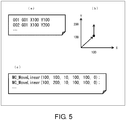
- (a) and (c) of FIG 5 show an example of the user program using each code.
- the motion control command may have a code indicating processing of the same content, corresponding to each of the command using G code, the command conforming to IEC61131-3, and the command using the robot language.
- G01 using G code, MC_MoveLinear using a code conforming to IEC61131-3, and MOVES using the robot language are all commands (command words) indicating the operation of linear interpolation.
- the user program is created by using these commands as shown in (a) and (c) of FIG. 5.
- (a) of FIG. 5 shows an example of the source file of the user program using G code.
- the command is described in each line.
- Each command of G code has one set of processing flow such as setting the destination coordinates, specifying the moving speed, starting the movement, and waiting until the movement is completed. The entire processing flow is completed, and one command ends.
- FIG. 5 is a diagram showing a locus of movement of a tool of a machine tool in an XY coordinate system when the user program shown in (a) of FIG. 5 is executed by the execution unit 620 of the controller 1.
- the execution unit 620 of the controller 1 moves the tool of the machine tool as shown by the arrow in (b) of FIG 5 by reading the source code shown in (a) of FIG. 5 line by line and executing the command of each line in order.
- FIG. 5 shows an example of the source file of the user program using codes conforming to IEC61131-3.
- the example shown in (c) of FIG. 5 is a source file that commands to perform linear interpolation to the position of X100 and Y100 and then perform linear interpolation to the position of X100 and Y200, as the user program using G code shown in (a) of FIG. 5 .
- control is further performed to move the tool of the machine tool at a speed of 10 mm/s, acceleration of 100 mm/s 2 , deceleration of 100 mm/s 2 , and jerk of 0.
- the program development device 5 includes a command word specifying unit 501, a user program editing unit 502, a user program building unit 503 (first building unit), a command word editing unit 504, a command word code checking unit 505, and a command word building unit 506 (second building unit).
- the user program editing unit 502 and the command word editing unit 504 are also collectively referred to as an editing unit.
- the program development device 5 includes a communication unit 507.
- the command word specifying unit 501 accepts an instruction of the user as to whether to prioritize the first motion control command or the second motion control command as the processing of the command word written in the source code of the user program executed by the controller 1. Thereby, the command word specifying unit 501 specifies whether to set the motion control command corresponding to the command word executed by the controller 1 to the default first motion control command or the user-defined second motion control command.
- the user program editing unit 502 edits the user program according to the instruction of the user.
- the user can edit the source code of the user program stored in the user program code saving unit 508.
- the user program stored in the user program code saving unit 508 may be overwritten or may be stored as a revision.
- the user program building unit 503 builds the source code of the user program.
- the user program building unit 503 compiles the user program into a binary (machine language) file and links it to the library. In the case of a CNC user program written in G code, it does not require building, so the user program building unit 503 does not perform building.
- the user program building unit 503 builds a PLC user program using codes conforming to IEC61131-3, or a robot control user program using a robot command word.
- the user program building unit 503 builds the source code in association with the second motion control command if the second motion control command corresponding to the command word written in the source code of the user program exists in the second command word storage unit 511. Further, the user program building unit 503 builds the source code in association with the first motion control command if the second motion control command corresponding to the command word written in the source code of the user program does not exist in the second command word storage unit 511.
- the user program building unit 503 builds the source code based on the prioritized control command specified by the command word specifying unit 501.
- the user program building unit 503 builds the source code in association with the first motion control command if the first motion control command is prioritized, and builds the source code in association with the second motion control command if the second motion control command is prioritized.
- the operation of the user program building unit 503 when the second motion control command is specified to be prioritized will be described.
- the user program building unit 503 builds the source code in association with the second motion control command if the second motion control command corresponding to the command word written in the source code of the user program exists in the second command word storage unit 511. Further, the user program building unit 503 builds the source code in association with the first motion control command if the second motion control command corresponding to the command word written in the source code of the user program does not exist in the second command word storage unit 511. That is, for example, if the user-defined MCMoveLinear exists for the command word called MC_MoveLinear written in the user program, the user program is linked to the user-defined second motion control command. If the user-defined MC MoveLinear does not exist for the command word called MC _MoveLinear, the user program is linked to the default second motion control command.
- the command word editing unit 504 edits the motion control command stored in association with the command word in the first command word storage unit 510 or the second command word storage unit 511 according to the instruction of the user.
- the motion control command edited by the command word editing unit 504 is stored in the second command word storage unit 511 as the second motion control command.
- the command word code checking unit 505 functions as a compiler that checks the code of the motion control command edited by the command word editing unit 504.
- the function of the command word code checking unit 505 may be provided in the command word building unit 506.
- the command word building unit 506 builds the second motion control command.
- the command word building unit 506 performs building regardless of whether the second motion control command is based on G code, codes conforming to IEC61131-3, or a robot command word.
- the communication unit 507 communicates with the controller 1.
- the communication unit 507 transmits the execution code of the second motion control command and the source code of the second motion control command to the controller 1. Further, the communication unit 507 may request the controller 1 to transmit the execution code of the second motion control command and the source code of the second motion control command, and receive the execution code of the second motion control command and the source code of the second motion control command from the controller 1.
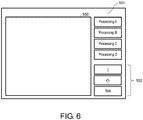
- FIG. 6 is a diagram showing an example of a display screen 551 at the time of editing of the processing flow in the program development device 5.
- selection buttons (processing A, processing B, processing C, processing D, etc.) indicating the typical processings may be displayed.
- the display screen 551 may display a control processing button 552 for inputting an arrow indicating the processing flow, a conditional branch, a text for comment, etc.
- the flow related to the processing is displayed on a flow display editing unit 550.
- the user can operate the control processing button 552 on the flow displayed by the flow display editing unit 550 to make changes such as adding a processing, deleting a processing, and changing the processing content.
- the user can also input a new processing name to generate the code of a command word.
- FIG. 7 is a flowchart showing a flow of editing of the processing flow.
- the user sets (specifies) the command word to be edited by operating the program development device 5.
- the user may be able to set the command word to be edited by either the name or the number.
- the user when editing the processing of G01, the user performs an operation of setting G01 on the program development device 5.
- the user may be able to set the command word to be edited to G01 by performing an operation of inputting or selecting G01 as the target command word to be edited on the processing flow editing screen of the program development device 5, for example.
- the program development device 5 determines whether the command word set by the user is new. For example, when the command word set by the user is G01, the command word is a default command word of G code, and therefore the program development device 5 determines that the command word set by the user is not new (NO in step S2) and proceeds to step S3. When the program development device 5 determines that the command word set by the user is new (YES in step S2), the program development device 5 proceeds to step S5.
- the program development device 5 displays the default processing flow of the command word set by the user on the flow display editing unit 550 of the display screen 551.
- the user specifies a part to be changed in the processing flow displayed on the flow display editing unit 550.
- the program development device 5 displays a screen for creating and editing a new processing flow on the display screen 551. As shown in FIG. 6 , the display screen 551 displays the selection buttons indicating the typical processings, the control processing button 552, and the flow display editing unit 550.
- the user creates the processing flow corresponding to the newly set command word on the display screen 551.
- step S4 and step S6 the user selects an icon displayed on the display screen 551, adds or deletes a processing, edits the content, and creates or edits the processing flow.
- the program development device 5 automatically generates the source code (for example, source code written in a high-level language) corresponding to the processing flow created or edited in step S4 or step S6 by the function of the editing unit. For example, the program development device 5 stores in advance the source code written in a high-level language corresponding to the processing flow.
- the source code for example, source code written in a high-level language
- the user may additionally implement (edit) the content by using a high-level language such as C or C++.
- the program development device 5 checks the grammar of the code implemented in step S8 by the function of the editing unit.
- the program development device 5 builds the code created, edited, or implemented by the function of the command word building unit 506.
- the program development device 5 confirms by simulation on the program development device 5 that the second motion control command of the built user-defined command word does not cause a call error of the firmware API 602 of the controller 1.
- the program development device 5 determines whether no call error of the firmware API 602 of the controller 1 occurs. The program development device 5 proceeds to step S14 if no error occurs (YES in step S12). The program development device 5 proceeds to step S13 if an error occurs (NO in step S12).
- the program development device 5 displays a part to be corrected on the display screen 551, returns to step S8, and requests a correction from the user.
- the program development device 5 completes the creation, editing, or additional implementation of the command word, and ends the processing.
- the program development device 5 transmits the second motion control command corresponding to the completed command word to the controller 1 via the communication unit 507 in association with the command word.
- the command word that has been created, edited, or additionally implemented is transmitted to the controller 1 after it is confirmed that a call error of the firmware API 602 does not occur.
- the program development device 5 it is possible to create a new command word and edit the default command word, and it is also possible to prevent these user-defined command words from affecting the behavior of the controller 1 and the control performed by the controller 1.
- the user can interactively set the creation of a new command word and the editing of the default command word by using the icon or the like displayed on the display screen 551 of the program development device 5, and furthermore, since the source code is automatically generated, the user can easily generate a user-defined command word. Further, since the user can additionally implement the processing to be changed by using a high-level language with respect to the processing flow of the command word, the user can accurately realize the control that the user desires to realize by the controller 1.
- FIG. 8 is a diagram showing an example of a default processing flow displayed on the flow display editing unit 550.
- FIG. 9 is a diagram showing an example of a user-defined processing flow displayed on the flow display editing unit 550 after the user has changed the processing flow shown in FIG. 8 .
- the processing flow defined by one command word includes a plurality of processes P1 to P5 such as setting the target position (process P1), setting the target speed (process P2), starting the operation (process P3), waiting for completion of the operation (process P4), and completing the operation (process P5).
- processes P1 to P5 such as setting the target position (process P1), setting the target speed (process P2), starting the operation (process P3), waiting for completion of the operation (process P4), and completing the operation (process P5).
- the user can also edit the respective parameters of the processes P1 to P5, and can also rearrange the order of the processes, delete the processes, and add new processes.
- the user can also edit to add processing for setting the second target position (process P15), starting the second operation (process P16), and waiting for completion of the second operation (process P17).
- the command word defined by the user is transferred to the controller 1 via the communication unit 507 and stored in the storage unit 610 of the controller 1.
- the execution unit 620 preferentially uses the command word stored in the user-defined command word group 601 to execute the motion control command.
- Steps S7 to S8 (direct editing in a high-level language) can be omitted. Steps S9 or S11 to S12 can be omitted. Furthermore, steps S3 to S6 may be omitted and steps S7 to S8 may be performed to directly edit the processing flow corresponding to the command word in a high-level language.
- the memory area used by the firmware may be specified by a pointer and data may be written.
- the operation of the firmware may become unstable.
- no countermeasures have been taken for the influence on the firmware and the operating system, and the operation of the PLC may become unstable.
- the execution of the second motion control command is controlled by the function of the firmware API (application program interface) 602, thereby preventing the second motion control command from adversely affecting the firmware and the operating system.
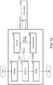
- FIG. 10 is a diagram schematically showing a flow of processing of the firmware API 602.
- the firmware API 602 has a function of transitioning between states of initializing (step S101), standing by (step S102), and finishing (step S105).
- the execution unit 620 of the controller 1 calls the firmware API 602 in order to execute the execution code of the second motion control command according to the user program.
- the firmware API 602 transitions the state from initializing to standing by.
- the firmware API 602 is in the first state that allows calling only at the time of standing by.
- the firmware API 602 is called while standing by, and when the execution code of the second motion control command is being executed, the firmware API 602 transitions to the second state that does not allow calling.
- the firmware API 602 that is called in the second state causes a call error.
- the firmware API 602 transitions to the state of standing by (step S102).
- the firmware API 602 stops the processing. When the stopping processing finishes, the firmware API 602 transitions to the state of standing by (step S102).
- the firmware API 602 terminates the function when the operation of the execution unit 620 of the controller 1 stops.
- firmware API 602 transitions to the second state that does not allow calling.
- the firmware API 602 maintains the second state and does not allow calling until the error in the firmware 603 is cleared.
- the firmware API 602 transitions to the second state that does not allow the firmware API 602 to be called during execution of the execution code of the second motion control command or occurrence of an error in the firmware 603. Thereby, it is possible to prevent unauthorized use of the firmware API 602, and prevent the firmware 603 and the operating system 604 from losing control or being deadlocked.
- control blocks of the controller 1 may be realized by logic circuits (hardware) formed in an integrated circuit (IC chip) or the like, or may be realized by software.
- the controller 1 and the program development device 5 include a computer that executes the commands of the program, which is software that realizes each function.
- the computer includes, for example, one or more processors and a computer-readable recording medium that stores the program. Then, in the computer, the processor reads the program from the recording medium and executes it, thereby achieving the object of the invention.
- a CPU Central Processing Unit
- non-transient tangible media such as ROM (Read Only Memory), tapes, disks, cards, semiconductor memories, programmable logic circuits, or the like can be used as the recording medium.
- a RAM Random Access Memory
- the program may be supplied to the computer via an arbitrary transmission medium (communication network, broadcast wave, etc.) capable of transmitting the program.
- a transmission medium communication network, broadcast wave, etc.
- One aspect of the invention can also be realized in the form of a data signal embedded in a carrier wave, in which the program is embodied by electronic transmission.
- a program development device is for creating a user program operating on a controller that controls motion of a machine.
- the program development device includes a first storage unit that stores a default first motion control command in association with a command word; and an editing unit that edits a motion control command corresponding to the command word according to an instruction of the user.
- the motion control command for controlling the motion of the machine can be edited in association with the command word according to the instruction of the user.
- the user it is possible for the user to change the processing content of the command word used for the motion control of the machine and add a new command word.
- the program development device may include a second storage unit that stores the edited motion control command as a second motion control command in association with the command word.
- the second motion control command for executing the user-defined processing can be saved separately from the default first motion control command in association with the command word without rewriting the default first motion control command.
- the program development device may include a first building unit that builds a source code of the user program, and a second building unit that builds the second motion control command.
- the first building unit builds the source code in association with the second motion control command if the second motion control command corresponding to the command word written in the source code exists in the second storage unit, and builds the source code in association with the first motion control command if the second motion control command corresponding to the command word written in the source code does not exist in the second storage unit.
- the source code of the user program is built in association with the second motion control command.
- the user program automatically executes the second motion control command. Therefore, by creating the second motion control command, the user can execute the second motion control command without separately specifying which of the first motion control command and the second motion control command is to be executed.
- the program development device may include a first building unit that builds a source code of the user program, a second building unit that builds the second motion control command, and a command word specifying unit that accepts the instruction of the user as to whether to prioritize the first motion control command or the second motion control command as processing of the command word written in the source code.
- the first building unit builds the source code in association with the first motion control command if the first motion control command is prioritized, and builds the source code in association with the second motion control command if the second motion control command is prioritized.
- the user can specify whether to prioritize the first motion control command or the second motion control command by the user operation.
- the user can also configure to be able to specify each time whether to execute the motion according to the first motion control command or execute the motion according to the second motion control command according to the parts to be made in the machine tool, for example.
- a controller for controlling motion of a machine according to a user program.
- the controller includes an execution unit that executes the user program; a first command library that stores an execution code of a default first motion control command, corresponding to a command word; and a second command library that stores an execution code of a second motion control command, which is defined by a user, corresponding to the command word.
- the execution unit decides whether to call the execution code of the first motion control command or the execution code of the second motion control command according to the user program.
- the controller may include a firmware API (application program interface) that transitions between a first state that allows calling and a second state that does not allow calling.
- the execution unit calls the firmware API in order to execute the execution code of the second motion control command if the execution code of the second motion control command is called according to the user program, and does not call the firmware API in order to execute the execution code of the first motion control command if the execution code of the first motion control command is called according to the user program.
- the memory area used by the firmware can be specified by execution of the execution code of the second motion control command, and the operation of the firmware can be prevented from becoming unstable.
- the firmware API may transition to the second state when starting execution of the execution code of the second motion control command, and transition to the first state when finishing execution of the execution code of the second motion control command.
- the firmware API since the firmware API is not allowed to be called during execution of the execution code of the second motion control command or occurrence of an error in the firmware, it is possible to prevent unauthorized use of the firmware API, and prevent the firmware and the operating system from losing control or being deadlocked.
- the execution unit may call the execution code of the second motion control command if the execution code corresponding to the command word written in the user program exists in the second command library, and call the execution code of the first motion control command if the execution code corresponding to the command word written in the user program does not exist in the second command library.
- the execution code of the second motion control command existing in the second command library can be preferentially called and executed. Therefore, the motion of the machine to be controlled can be controlled by the second motion control command corresponding to the user-defined command word.
- the controller may include a communication unit that communicates with a program development device which creates the user program.
- the communication unit receives the execution code of the second motion control command and a source code of the second motion control command from the program development device, and stores the execution code of the second motion control command and the source code of the second motion control command in the second command library, and transmits the execution code of the second motion control command and the source code of the second motion control command stored in the second command library to another program development device in response to a request from the another program development device.
- the content of the operation can be known by another program development device.
Landscapes
- Engineering & Computer Science (AREA)
- Software Systems (AREA)
- General Engineering & Computer Science (AREA)
- Physics & Mathematics (AREA)
- General Physics & Mathematics (AREA)
- Theoretical Computer Science (AREA)
- Automation & Control Theory (AREA)
- Programmable Controllers (AREA)
- Stored Programmes (AREA)
Abstract
Description
- The invention relates to a program development device and a controller.
- The command words (individual codes in the program source) used for motion control of machines such as PLCs (Programmable Logic Controllers), machine tools, and robots may be standardized or systematized respectively for use. A code conforming to IEC61131-3 (JIS B 3503) is, for example, a command word for PLC. In addition, a G code used in CNC (Computer Numerical Control) is also standardized by ISO and can be used as a command word.
- Conventionally, PLCs and machine tools have a configuration that does not allow the user to change the processing content of a command word or add a new command word in order to guarantee the operation.
- Therefore, for PLC, there is a technique that converts a part of a user program into a library and saves it in a unit so as to implement the user's know-how in the user program and improve the reusability of the user program (for example, see
Patent Document 1 and Patent Document 2). -
- [Patent Document 1] Japanese Patent Gazette "specification of Patent No.
35488829 - [Patent Document 2] Japanese Patent Gazette "specification of Patent No.
4973867 - However, in the technique described in
Patent Document 1 orPatent Document 2, in order to prevent the firmware or operating system from losing control or being deadlocked due to unauthorized use of the API provided by the firmware or operating system, the user could create a library of a user program using the command words provided by the manufacturer. The library is a user program written in IEC61131-3 that is made into a component in the form of a function block or a function, and can improve the reusability of the program or conceal the user program. However, the command words provided by the manufacturer may have functional restrictions in order to guarantee the operation, so the functions that can be realized with the library, which is a combination of command words, are limited, and the user cannot make changes as desired. - One aspect of the invention has been made in view of the above circumstances, and one aspect of the invention is to provide a technique that allows the user to change the processing content of a command word used for the motion control of a machine and add a new command word, thereby realizing a new function not defined by the manufacturer.
- To solve the above problems, a program development device according to one aspect of the invention is for creating a user program operating on a controller that controls motion of a machine. The program development device includes a first storage unit that stores a default first motion control command in association with a command word; and an editing unit that edits a motion control command corresponding to the command word according to an instruction of a user.
- To solve the above problems, a controller according to one aspect of the invention is for controlling motion of a machine according to a user program. The controller includes an execution unit that executes the user program; a first command library that stores an execution code of a default first motion control command corresponding to a command word; and a second command library that stores an execution code of a second motion control command, which is defined by a user, corresponding to the command word. The execution unit decides whether to call the execution code of the first motion control command or the execution code of the second motion control command according to the user program.
- According to one aspect of the invention, the user can change the processing content of a command word used for the motion control of a machine and add a new command word.
-
-
FIG 1 is a block diagram showing a schematic configuration of a system environment in which the program development device and the controller according to an embodiment of the invention are used. -
FIG 2 is a block diagram showing a main configuration of the controller. -
FIG 3 is a block diagram showing a main configuration of the program development device. -
FIG. 4 is a comparison table showing codes based on each standard and default processing contents thereof.
(a) ofFIG. 5 shows an example of a user program using G codes, (b) ofFIG 5 is a diagram showing a locus of movement of a tool of a machine tool according to the user program shown in (a) in an XY coordinate system, and (c) ofFIG. 5 shows an example of a user program using codes conforming to IEC61131-3. -
FIG. 6 is a diagram showing an example of a display screen of the program development device. -
FIG. 7 is a flowchart showing a flow of editing of a processing flow. -
FIG. 8 is a diagram showing an example of a default processing flow. -
FIG. 9 is a diagram showing an example of a user-defined processing flow. -
FIG. 10 is a diagram showing a flow of processing of a firmware AP. - Hereinafter, an embodiment according to one aspect of the invention (hereinafter, also referred to as "the present embodiment") will be described with reference to the drawings.
- First, an example of a situation to which the invention is applied will be described with reference to
FIG. 1. FIG. 1 is a diagram showing an outline of a system environment in which aprogram development device 5 and acontroller 1 according to the present embodiment are used. Thecontroller 1 controls the motion of a machine connected via amotion network cable 2. Thecontroller 1 is, for example, a PLC, a machine tool controller, a robot controller, or the like. When thecontroller 1 is a machine tool controller, for example, thecontroller 1 is connected to aservo driver 200 via themotion network cable 2 and drives aservo motor 201 connected to theservo driver 200. EtherCAT (registered trademark) is used as the motion network, for example. - The
program development device 5 has a function of editing a user program and a command word according to a user operation. Further, theprogram development device 5 checks the codes of the edited command word and determines whether the machine to be controlled by thecontroller 1 operates normally. In addition, theprogram development device 5 builds the edited user program and command word, converts them into an executable file format, and then transfers and saves them in thecontroller 1. - The user can change the processing content of the command word and add a new command word by operating the
program development device 5. In theprogram development device 5, the user can set the processing content that the user wants to realize in the command word in an interactive manner with theprogram development device 5. Theprogram development device 5 generates the processing content set by the user in a high-level language such as C or C++. In addition, in theprogram development device 5, the user can also program the processing content that the user wants to realize in the command word in a high-level language such as C or C++. - The user program and command word edited by the user are generated after the simulation confirms that a call error of the API of the controller firmware does not occur. Moreover, since the API of the controller firmware can be executed only when the firmware is on standby, it has a configuration that retains the firmware state, accepts API processing when it is in an acceptable state, and returns an error when it is in an unacceptable state. Therefore, the firmware is prevented from entering an unauthorized state.
- Thus, in the system environment in which the
program development device 5 and thecontroller 1 according to the present embodiment are used, the user can change the processing content of the command word used for the motion control of the machine and add a new command word. In addition, theprogram development device 5 can implement the edited user program and command word on thecontroller 1 after it is confirmed that the motion control of the machine is normally performed by using the API of the controller firmware. - Hereinafter, the configurations of the
program development device 5 and thecontroller 1 according to an embodiment of the invention will be described in detail with reference toFIG 1 ,FIG. 2 , andFIG. 3 .FIG. 1 is a diagram showing the outline of the system environment in which theprogram development device 5 and thecontroller 1 are used.FIG. 2 is a block diagram showing a main configuration of thecontroller 1.FIG. 3 is a block diagram showing a main configuration of theprogram development device 5. - As shown in
FIG. 1 , thecontroller 1 is connected to theservo driver 200 of the machine tool to be controlled via themotion network cable 2 and drives theservo motor 201 connected to theservo driver 200. The machine tool to be controlled by thecontroller 1 includes a plurality ofservo drivers 200, and by driving theservo motors 201 respectively connected to theservo drivers 200, machines a machining target part. AlthoughFIG. 1 shows a configuration in which thecontroller 1 controls the motion of the machine tool, thecontroller 1 is not limited to a controller of a machine tool, and may be a PLC or a robot controller. - In addition to the
servo drivers 200, acommunication coupler 202 can be connected to thecontroller 1 via themotion network cable 2. AlthoughFIG. 1 shows an example in which the connection is realized by a daisy chain method, theservo drivers 200 and thecommunication coupler 202 may be connected by other connection methods. Further, a general-purposeanalog output unit 205, a general-purposeanalog input unit 204, and a general-purpose digital input/output unit 203 can exchange data with thecommunication coupler 202 via an internal bus. - Furthermore, a
touch panel 4 is connected to thecontroller 1 via anetwork HUB 3. Thetouch panel 4 is an operation panel of thecontroller 1. Thetouch panel 4 may be attached to the machine tool or robot to be controlled, or may be provided separately from the machine tool or robot to be controlled. - In addition, the
program development device 5 is connected to thecontroller 1 by an Ethernet (registered trademark)cable 301 via thenetwork HUB 3. Theprogram development device 5 is, for example, a general-purpose computer. Theprogram development device 5 stores the user program executed by thecontroller 1 and the command word used for the motion control of the machine tool by thecontroller 1. Although details will be described later, the user can edit the user program and the command word to be executed in thecontroller 1 by operating theprogram development device 5. - As shown in
FIG. 2 , thecontroller 1 includes an interface 607 (communication unit) that transmits and receives data to and from theprogram development device 5, and is connected to theprogram development device 5 via theinterface 607. Thecontroller 1 includes amotion network unit 608 that is an interface for transmitting and receiving data to and from theservo driver 200. Themotion network unit 608 communicates with theservo driver 200 via amotion network port 101. - The
controller 1 includes astorage unit 610 and anexecution unit 620. In addition, thecontroller 1 includes a firmware API (application program interface) 602,firmware 603, an operating system (OS) 604, and adevice driver 605. In the following descriptions, for those that describe the functions of each unit without a special distinction between hardware and software, some or all of the functions of each unit may be executed by either hardware or software, or may be executed by collaboration between hardware and software. - The
storage unit 610 stores auser program 606, a manufacturer-definedcommand word group 600, and a user-definedcommand word group 601. Each of theuser program 606, the manufacturer-definedcommand word group 600, and the user-definedcommand word group 601 stores a program written in codes conforming to IEC61131-3 when thecontroller 1 is a PLC, and a program written in G codes standardized by ISO when thecontroller 1 is a motion controller of a machine tool. - The
user program 606 is a program executed on thecontroller 1 and is a program that controls the operation of thecontroller 1. In other words, thecontroller 1 controls the motion of the machine to be controlled according to the user program. - When the
controller 1 is a PLC, theuser program 606 is built and stored in thestorage unit 610 in a binary format. When thecontroller 1 is a controller of a machine tool, the CNC user program is not built, and the source code written in G codes is stored in thestorage unit 610 in a text format. - The manufacturer-defined
command word group 600 includes a plurality of command words, and default processing contents which are realized by the command words and associated with the respective command words. The default processing content refers to the content of processing associated with each command word, which is defined by the manufacturer that manufactures thecontroller 1, and is, for example, the content of processing according to the G codes conforming to the ISO standard. The control command for executing the default processing, which corresponds to the command word, is referred to as a first motion control command. - The manufacturer-defined
command word group 600 includes a library, which is an execution code of the first motion control command, in a built binary format in association with each command word. In thestorage unit 610, the area for storing the manufacturer-definedcommand word group 600 is also referred to as a first command library. - The user-defined
command word group 601 includes a plurality of command words, and processing contents defined by the user, which are realized by the command words and associated with the respective command words. The control command for executing the user-defined processing, which corresponds to the command word, is referred to as a second motion control command. The user-definedcommand word group 601 includes a user-defined command word, which is an execution code of the second motion control command, in a built binary format in association with each command word. In thestorage unit 610, the area for storing the user-definedcommand word group 601 is also referred to as a second command library. - The
execution unit 620 loads and executes the user program and the command library stored in thestorage unit 610. Theexecution unit 620 may be composed of, for example, a CPU as an arithmetic device and a memory. Theexecution unit 620 decides whether to call the default command word stored in the manufacturer-definedcommand word group 600 or the user-defined command word stored in the user-definedcommand word group 601 according to the user program. - When the
controller 1 is a PLC and the user program is a compiler type program, the user program writes whether to call the execution code of the first motion control command or the execution code of the second motion control command. By executing the user program, theexecution unit 620 can decide whether to call the execution code existing in the first command library or call the execution code existing in the second command library. - In addition, when the user program is a CNC user program, the
execution unit 620 reads the source file of the user program line by line and executes the commands of each line in order. If the execution code corresponding to the command word written in the user program exists in the second command library, theexecution unit 620 calls the execution code of the second motion control command. If the execution code corresponding to the command word written in the user program does not exist in the second command library, theexecution unit 620 calls the execution code of the first motion control command from the first command library. - The
firmware API 602 is called by theexecution unit 620 that executes the user-defined command word. The firmware API transitions between a first state that allows calling of theexecution unit 620 and a second state that does not allow calling. - When the
execution unit 620 calls the execution code of the second motion control command according to the user program, thefirmware API 602 is called by theexecution unit 620 in order to execute the execution code of the second motion control command. However, when theexecution unit 620 calls the execution code of the first motion control command according to the user program, thefirmware API 602 is not called in order to execute the execution code of the first motion control command. - When the firmware API is called by the
execution unit 620 to start the execution of the execution code of the second motion control command, the firmware API transitions to the second state that does not allow calling again. Furthermore, when theexecution unit 620 finishes the execution of the execution code of the second motion control command, the firmware API transitions to the first state that allows calling. - The
firmware 603 operates the machine to be controlled according to the motion control command executed by theexecution unit 620. - The
operating system 604 is the system software of thecontroller 1, and controls each unit of thecontroller 1 integrally. - The
device driver 605 is software for enabling theoperating system 604 to control hardware devices such as the Ethernet (registered trademark)port 100 and themotion network port 101 of thecontroller 1. Thefirmware 603 and theoperating system 604 communicate with the control target such as theservo driver 200 connected to themotion network port 101 via thedevice driver 605 to control the control target. In addition, theoperating system 604 transmits and receives data to and from theprogram development device 5 connected to the Ethernet (registered trademark)port 100 via thedevice driver 605. - The
controller 1 communicates with theprogram development device 5 via theinterface 607, and receives the execution code of the second motion control command and the source code of the second motion control command from theprogram development device 5. In addition, theinterface 607 includes (stores) the received execution code of the second motion control command and source code of the second motion control command in the user-definedcommand word group 601 of thestorage unit 610. - Further, the
controller 1 may be configured to be connected to a plurality ofprogram development devices 5 via theinterface 607. Then, theinterface 607 may transmit the execution code of the second motion control command and the source code of the second motion control command received from theprogram development device 5 and stored in thestorage unit 610 to another program development device in response to a request from another program development device. Thereby, when a user-defined command word is used for the user program operating on thecontroller 1, the content of the operation can also be known by another program development device. - As shown in
FIG 3 , theprogram development device 5 provides a program development environment for creating a user program that operates on thecontroller 1. Theprogram development device 5 includes a user programcode saving unit 508, a user program executionfile saving unit 509, a first commandword storage unit 510, and a second commandword storage unit 511. - The user program
code saving unit 508 saves the same source code as the source code written in theuser program 606 of thecontroller 1. - The user program execution
file saving unit 509 saves the same execution file as the execution file of the user program written in theuser program 606 of thecontroller 1. Further, in this way, the source code of the user program and the execution file are separately saved in theprogram development device 5. - The first command word storage unit 510 (first storage unit) stores the first motion control command for executing the default processing defined by the manufacturer that manufactures the
controller 1 in association with the command word. The first commandword storage unit 510 stores the source code, the execution code, and the processing content corresponding to the default first motion control command included in the manufacturer-definedcommand word group 600 of thecontroller 1 in association with the command word. - The second command word storage unit 511 (second storage unit) stores the second motion control command for executing the processing defined by the user in association with the command word. The second command
word storage unit 511 stores the source code, the execution code, and the processing content corresponding to the user-defined second motion control command included in the user-definedcommand word group 601 in association with the command word. - In this way, the source codes included in the
user program 606, the manufacturer-definedcommand word group 600, and the user-definedcommand word group 601 of thecontroller 1 and the codes corresponding to the execution codes are saved in theprogram development device 5. - Here, the motion control command will be described.
FIG. 4 is a comparison table showing the codes based on each standard and the default processing contents thereof. (a) and (c) ofFIG 5 show an example of the user program using each code. As shown inFIG. 4 , the motion control command may have a code indicating processing of the same content, corresponding to each of the command using G code, the command conforming to IEC61131-3, and the command using the robot language. For example, G01 using G code, MC_MoveLinear using a code conforming to IEC61131-3, and MOVES using the robot language are all commands (command words) indicating the operation of linear interpolation. - The user program is created by using these commands as shown in (a) and (c) of
FIG. 5.(a) ofFIG. 5 shows an example of the source file of the user program using G code. As shown in (a) ofFIG. 5 , in the user program using G code, the command is described in each line. The command in the 001 line commands to perform linear interpolation (straight line movement) to the position of X100 and Y100, and the command in the 002 line commands to perform linear interpolation to the position of X100 and Y200. - Each command of G code has one set of processing flow such as setting the destination coordinates, specifying the moving speed, starting the movement, and waiting until the movement is completed. The entire processing flow is completed, and one command ends.
- (b) of
FIG. 5 is a diagram showing a locus of movement of a tool of a machine tool in an XY coordinate system when the user program shown in (a) ofFIG. 5 is executed by theexecution unit 620 of thecontroller 1. Theexecution unit 620 of thecontroller 1 moves the tool of the machine tool as shown by the arrow in (b) ofFIG 5 by reading the source code shown in (a) ofFIG. 5 line by line and executing the command of each line in order. - Furthermore, (c) of
FIG. 5 shows an example of the source file of the user program using codes conforming to IEC61131-3. In the user program using IEC61131-3, it is possible to specify the speed, acceleration, deceleration, and jerk in addition to the direction of movement by commands. The example shown in (c) ofFIG. 5 is a source file that commands to perform linear interpolation to the position of X100 and Y100 and then perform linear interpolation to the position of X100 and Y200, as the user program using G code shown in (a) ofFIG. 5 . In the user program using IEC61131-3, control is further performed to move the tool of the machine tool at a speed of 10 mm/s, acceleration of 100 mm/s2, deceleration of 100 mm/s2, and jerk of 0. - The
program development device 5 includes a commandword specifying unit 501, a userprogram editing unit 502, a user program building unit 503 (first building unit), a commandword editing unit 504, a command wordcode checking unit 505, and a command word building unit 506 (second building unit). The userprogram editing unit 502 and the commandword editing unit 504 are also collectively referred to as an editing unit. Further, theprogram development device 5 includes acommunication unit 507. - The command
word specifying unit 501 accepts an instruction of the user as to whether to prioritize the first motion control command or the second motion control command as the processing of the command word written in the source code of the user program executed by thecontroller 1. Thereby, the commandword specifying unit 501 specifies whether to set the motion control command corresponding to the command word executed by thecontroller 1 to the default first motion control command or the user-defined second motion control command. - The user
program editing unit 502 edits the user program according to the instruction of the user. The user can edit the source code of the user program stored in the user programcode saving unit 508. The user program stored in the user programcode saving unit 508 may be overwritten or may be stored as a revision. - The user
program building unit 503 builds the source code of the user program. The userprogram building unit 503 compiles the user program into a binary (machine language) file and links it to the library. In the case of a CNC user program written in G code, it does not require building, so the userprogram building unit 503 does not perform building. The userprogram building unit 503 builds a PLC user program using codes conforming to IEC61131-3, or a robot control user program using a robot command word. - The user
program building unit 503 builds the source code in association with the second motion control command if the second motion control command corresponding to the command word written in the source code of the user program exists in the second commandword storage unit 511. Further, the userprogram building unit 503 builds the source code in association with the first motion control command if the second motion control command corresponding to the command word written in the source code of the user program does not exist in the second commandword storage unit 511. - The user
program building unit 503 builds the source code based on the prioritized control command specified by the commandword specifying unit 501. The userprogram building unit 503 builds the source code in association with the first motion control command if the first motion control command is prioritized, and builds the source code in association with the second motion control command if the second motion control command is prioritized. - The operation of the user
program building unit 503 when the second motion control command is specified to be prioritized will be described. The userprogram building unit 503 builds the source code in association with the second motion control command if the second motion control command corresponding to the command word written in the source code of the user program exists in the second commandword storage unit 511. Further, the userprogram building unit 503 builds the source code in association with the first motion control command if the second motion control command corresponding to the command word written in the source code of the user program does not exist in the second commandword storage unit 511. That is, for example, if the user-defined MCMoveLinear exists for the command word called MC_MoveLinear written in the user program, the user program is linked to the user-defined second motion control command. If the user-defined MC MoveLinear does not exist for the command word called MC _MoveLinear, the user program is linked to the default second motion control command. - The command
word editing unit 504 edits the motion control command stored in association with the command word in the first commandword storage unit 510 or the second commandword storage unit 511 according to the instruction of the user. - The motion control command edited by the command
word editing unit 504 is stored in the second commandword storage unit 511 as the second motion control command. - The command word
code checking unit 505 functions as a compiler that checks the code of the motion control command edited by the commandword editing unit 504. The function of the command wordcode checking unit 505 may be provided in the commandword building unit 506. - The command
word building unit 506 builds the second motion control command. The commandword building unit 506 performs building regardless of whether the second motion control command is based on G code, codes conforming to IEC61131-3, or a robot command word. - The
communication unit 507 communicates with thecontroller 1. Thecommunication unit 507 transmits the execution code of the second motion control command and the source code of the second motion control command to thecontroller 1. Further, thecommunication unit 507 may request thecontroller 1 to transmit the execution code of the second motion control command and the source code of the second motion control command, and receive the execution code of the second motion control command and the source code of the second motion control command from thecontroller 1. -
FIG. 6 is a diagram showing an example of adisplay screen 551 at the time of editing of the processing flow in theprogram development device 5. On thedisplay screen 551, selection buttons (processing A, processing B, processing C, processing D, etc.) indicating the typical processings may be displayed. In addition, thedisplay screen 551 may display acontrol processing button 552 for inputting an arrow indicating the processing flow, a conditional branch, a text for comment, etc. - When the user selects the processing that the user desires to edit from the selection buttons indicating the typical processings, the flow related to the processing is displayed on a flow
display editing unit 550. The user can operate thecontrol processing button 552 on the flow displayed by the flowdisplay editing unit 550 to make changes such as adding a processing, deleting a processing, and changing the processing content. In addition, the user can also input a new processing name to generate the code of a command word. -
FIG. 7 is a flowchart showing a flow of editing of the processing flow. - The user sets (specifies) the command word to be edited by operating the
program development device 5. The user may be able to set the command word to be edited by either the name or the number. For example, when editing the processing of G01, the user performs an operation of setting G01 on theprogram development device 5. The user may be able to set the command word to be edited to G01 by performing an operation of inputting or selecting G01 as the target command word to be edited on the processing flow editing screen of theprogram development device 5, for example. - The
program development device 5 determines whether the command word set by the user is new. For example, when the command word set by the user is G01, the command word is a default command word of G code, and therefore theprogram development device 5 determines that the command word set by the user is not new (NO in step S2) and proceeds to step S3. When theprogram development device 5 determines that the command word set by the user is new (YES in step S2), theprogram development device 5 proceeds to step S5. - The
program development device 5 displays the default processing flow of the command word set by the user on the flowdisplay editing unit 550 of thedisplay screen 551. - The user specifies a part to be changed in the processing flow displayed on the flow
display editing unit 550. - The
program development device 5 displays a screen for creating and editing a new processing flow on thedisplay screen 551. As shown inFIG. 6 , thedisplay screen 551 displays the selection buttons indicating the typical processings, thecontrol processing button 552, and the flowdisplay editing unit 550. - The user creates the processing flow corresponding to the newly set command word on the
display screen 551. - In step S4 and step S6, the user selects an icon displayed on the
display screen 551, adds or deletes a processing, edits the content, and creates or edits the processing flow. - The
program development device 5 automatically generates the source code (for example, source code written in a high-level language) corresponding to the processing flow created or edited in step S4 or step S6 by the function of the editing unit. For example, theprogram development device 5 stores in advance the source code written in a high-level language corresponding to the processing flow. - With respect to a processing to be changed in the processing flow created or edited in step S4 and step S6, the user may additionally implement (edit) the content by using a high-level language such as C or C++.
- The
program development device 5 checks the grammar of the code implemented in step S8 by the function of the editing unit. - The
program development device 5 builds the code created, edited, or implemented by the function of the commandword building unit 506. - The
program development device 5 confirms by simulation on theprogram development device 5 that the second motion control command of the built user-defined command word does not cause a call error of thefirmware API 602 of thecontroller 1. - The
program development device 5 determines whether no call error of thefirmware API 602 of thecontroller 1 occurs. Theprogram development device 5 proceeds to step S14 if no error occurs (YES in step S12). Theprogram development device 5 proceeds to step S13 if an error occurs (NO in step S12). - The
program development device 5 displays a part to be corrected on thedisplay screen 551, returns to step S8, and requests a correction from the user. - The
program development device 5 completes the creation, editing, or additional implementation of the command word, and ends the processing. Theprogram development device 5 transmits the second motion control command corresponding to the completed command word to thecontroller 1 via thecommunication unit 507 in association with the command word. - Thus, in the
program development device 5, the command word that has been created, edited, or additionally implemented is transmitted to thecontroller 1 after it is confirmed that a call error of thefirmware API 602 does not occur. Thus, with theprogram development device 5, it is possible to create a new command word and edit the default command word, and it is also possible to prevent these user-defined command words from affecting the behavior of thecontroller 1 and the control performed by thecontroller 1. - In addition, the user can interactively set the creation of a new command word and the editing of the default command word by using the icon or the like displayed on the
display screen 551 of theprogram development device 5, and furthermore, since the source code is automatically generated, the user can easily generate a user-defined command word. Further, since the user can additionally implement the processing to be changed by using a high-level language with respect to the processing flow of the command word, the user can accurately realize the control that the user desires to realize by thecontroller 1. -
FIG. 8 is a diagram showing an example of a default processing flow displayed on the flowdisplay editing unit 550.FIG. 9 is a diagram showing an example of a user-defined processing flow displayed on the flowdisplay editing unit 550 after the user has changed the processing flow shown inFIG. 8 . - As shown in
FIG. 8 , the processing flow defined by one command word (for example, G01 or MC _MoveLinear) includes a plurality of processes P1 to P5 such as setting the target position (process P1), setting the target speed (process P2), starting the operation (process P3), waiting for completion of the operation (process P4), and completing the operation (process P5). By operating theprogram development device 5, the user can also edit the respective parameters of the processes P1 to P5, and can also rearrange the order of the processes, delete the processes, and add new processes. - For example, as shown in
FIG. 9 , after setting the target position (process P1), setting the target speed (process P2), starting the operation (process P3), and waiting for completion of the operation (process P4), the user can also edit to add processing for setting the second target position (process P15), starting the second operation (process P16), and waiting for completion of the second operation (process P17). - In this way, the command word defined by the user is transferred to the
controller 1 via thecommunication unit 507 and stored in thestorage unit 610 of thecontroller 1. - If it is specified to prioritize the user-defined second motion control command, as described above, the
execution unit 620 preferentially uses the command word stored in the user-definedcommand word group 601 to execute the motion control command. - Steps S7 to S8 (direct editing in a high-level language) can be omitted. Steps S9 or S11 to S12 can be omitted. Furthermore, steps S3 to S6 may be omitted and steps S7 to S8 may be performed to directly edit the processing flow corresponding to the command word in a high-level language.
- By the way, there is a technique that makes it possible to call a C language application program, which operates on a microprocessor different from a ladder language application program, as a function from the ladder language application program used in PLC.
- When a C language application program is called as a function from an application program executed on PLC as in the above technique, the memory area used by the firmware may be specified by a pointer and data may be written. In such a case, there is a problem that the operation of the firmware may become unstable. In addition, in the conventional technique, no countermeasures have been taken for the influence on the firmware and the operating system, and the operation of the PLC may become unstable.
- In the present embodiment, the execution of the second motion control command is controlled by the function of the firmware API (application program interface) 602, thereby preventing the second motion control command from adversely affecting the firmware and the operating system.
-
FIG. 10 is a diagram schematically showing a flow of processing of thefirmware API 602. As shown inFIG. 10 , thefirmware API 602 has a function of transitioning between states of initializing (step S101), standing by (step S102), and finishing (step S105). - The
execution unit 620 of thecontroller 1 calls thefirmware API 602 in order to execute the execution code of the second motion control command according to the user program. Thefirmware API 602 transitions the state from initializing to standing by. - The
firmware API 602 is in the first state that allows calling only at the time of standing by. - The
firmware API 602 is called while standing by, and when the execution code of the second motion control command is being executed, thefirmware API 602 transitions to the second state that does not allow calling. Thefirmware API 602 that is called in the second state causes a call error. - When the execution code of the second motion control command finishes, the
firmware API 602 transitions to the state of standing by (step S102). - If an abnormality of the
firmware API 602 or an abnormality of the execution code of the second motion control command occurs when the execution code of the second motion control command is being executed, thefirmware API 602 stops the processing. When the stopping processing finishes, thefirmware API 602 transitions to the state of standing by (step S102). - The
firmware API 602 terminates the function when the operation of theexecution unit 620 of thecontroller 1 stops. - Further, if an error occurs in the
firmware 603, thefirmware API 602 transitions to the second state that does not allow calling. Thefirmware API 602 maintains the second state and does not allow calling until the error in thefirmware 603 is cleared. - Thus, in the present embodiment, the
firmware API 602 transitions to the second state that does not allow thefirmware API 602 to be called during execution of the execution code of the second motion control command or occurrence of an error in thefirmware 603. Thereby, it is possible to prevent unauthorized use of thefirmware API 602, and prevent thefirmware 603 and theoperating system 604 from losing control or being deadlocked. - The control blocks of the controller 1 (particularly, the
execution unit 620, thefirmware 603, and the firmware API 602), and the control blocks of the program development device 5 (particularly, the commandword specifying unit 501, the userprogram editing unit 502, the userprogram building unit 503, the commandword editing unit 504, the command wordcode checking unit 505, and the command word building unit 506) may be realized by logic circuits (hardware) formed in an integrated circuit (IC chip) or the like, or may be realized by software. - In the latter case, the
controller 1 and theprogram development device 5 include a computer that executes the commands of the program, which is software that realizes each function. The computer includes, for example, one or more processors and a computer-readable recording medium that stores the program. Then, in the computer, the processor reads the program from the recording medium and executes it, thereby achieving the object of the invention. For example, a CPU (Central Processing Unit) can be used as the processor. In addition to "non-transient tangible media" such as ROM (Read Only Memory), tapes, disks, cards, semiconductor memories, programmable logic circuits, or the like can be used as the recording medium. Further, a RAM (Random Access Memory) for developing the program may be further provided. Further, the program may be supplied to the computer via an arbitrary transmission medium (communication network, broadcast wave, etc.) capable of transmitting the program. One aspect of the invention can also be realized in the form of a data signal embedded in a carrier wave, in which the program is embodied by electronic transmission. - A program development device according to one aspect of the invention is for creating a user program operating on a controller that controls motion of a machine. The program development device includes a first storage unit that stores a default first motion control command in association with a command word; and an editing unit that edits a motion control command corresponding to the command word according to an instruction of the user.
- According to the above configuration, the motion control command for controlling the motion of the machine can be edited in association with the command word according to the instruction of the user. Thus, it is possible for the user to change the processing content of the command word used for the motion control of the machine and add a new command word.
- Further, the program development device according to one aspect of the invention may include a second storage unit that stores the edited motion control command as a second motion control command in association with the command word.
- According to the above configuration, the second motion control command for executing the user-defined processing can be saved separately from the default first motion control command in association with the command word without rewriting the default first motion control command.
- In addition, the program development device according to one aspect of the invention may include a first building unit that builds a source code of the user program, and a second building unit that builds the second motion control command. The first building unit builds the source code in association with the second motion control command if the second motion control command corresponding to the command word written in the source code exists in the second storage unit, and builds the source code in association with the first motion control command if the second motion control command corresponding to the command word written in the source code does not exist in the second storage unit.
- According to the above configuration, if the second motion control command exists in the second storage unit, the source code of the user program is built in association with the second motion control command. Thus, if the user-defined second motion control command exists, the user program automatically executes the second motion control command. Therefore, by creating the second motion control command, the user can execute the second motion control command without separately specifying which of the first motion control command and the second motion control command is to be executed.
- Further, the program development device according to one aspect of the invention may include a first building unit that builds a source code of the user program, a second building unit that builds the second motion control command, and a command word specifying unit that accepts the instruction of the user as to whether to prioritize the first motion control command or the second motion control command as processing of the command word written in the source code. The first building unit builds the source code in association with the first motion control command if the first motion control command is prioritized, and builds the source code in association with the second motion control command if the second motion control command is prioritized.
- According to the above configuration, the user can specify whether to prioritize the first motion control command or the second motion control command by the user operation. Thus, the user can also configure to be able to specify each time whether to execute the motion according to the first motion control command or execute the motion according to the second motion control command according to the parts to be made in the machine tool, for example.
- Further, a controller according to one aspect of the invention is for controlling motion of a machine according to a user program. The controller includes an execution unit that executes the user program; a first command library that stores an execution code of a default first motion control command, corresponding to a command word; and a second command library that stores an execution code of a second motion control command, which is defined by a user, corresponding to the command word. The execution unit decides whether to call the execution code of the first motion control command or the execution code of the second motion control command according to the user program.
- According to the above configuration, it is possible to control the motion of the machine by calling either the execution code of the default first motion control command or the execution code of the user-defined second motion control command. Therefore, by calling the execution code of the second motion control command defined by the user, it is possible to enable the machine to execute the motion desired by the user.
- Further, the controller according to one aspect of the invention may include a firmware API (application program interface) that transitions between a first state that allows calling and a second state that does not allow calling. The execution unit calls the firmware API in order to execute the execution code of the second motion control command if the execution code of the second motion control command is called according to the user program, and does not call the firmware API in order to execute the execution code of the first motion control command if the execution code of the first motion control command is called according to the user program.
- According to the above configuration, with the firmware API, the memory area used by the firmware can be specified by execution of the execution code of the second motion control command, and the operation of the firmware can be prevented from becoming unstable.
- Further, in the controller according to one aspect of the invention, the firmware API may transition to the second state when starting execution of the execution code of the second motion control command, and transition to the first state when finishing execution of the execution code of the second motion control command.
- According to the above configuration, since the firmware API is not allowed to be called during execution of the execution code of the second motion control command or occurrence of an error in the firmware, it is possible to prevent unauthorized use of the firmware API, and prevent the firmware and the operating system from losing control or being deadlocked.
- Further, in the controller according to one aspect of the invention, the execution unit may call the execution code of the second motion control command if the execution code corresponding to the command word written in the user program exists in the second command library, and call the execution code of the first motion control command if the execution code corresponding to the command word written in the user program does not exist in the second command library.
- According to the above configuration, the execution code of the second motion control command existing in the second command library can be preferentially called and executed. Therefore, the motion of the machine to be controlled can be controlled by the second motion control command corresponding to the user-defined command word.
- In addition, the controller according to one aspect of the invention may include a communication unit that communicates with a program development device which creates the user program. The communication unit receives the execution code of the second motion control command and a source code of the second motion control command from the program development device, and stores the execution code of the second motion control command and the source code of the second motion control command in the second command library, and transmits the execution code of the second motion control command and the source code of the second motion control command stored in the second command library to another program development device in response to a request from the another program development device.
- According to the above configuration, when the user-defined command word is used for the user program operating on the controller, the content of the operation can be known by another program development device.
- The invention is not limited to the above-described embodiments, and it is possible to make various modifications within the scope of the claims. Embodiments obtained by appropriately combining the technical means disclosed in different embodiments are also included in the technical scope of the invention.
-
- 1
- controller
- 5
- program development device
- 501
- command word specifying unit
- 502
- user program editing unit (editing unit)
- 503
- user program building unit
- 504
- command word editing unit (editing unit)
- 505
- command word code checking unit
- 506
- command word building unit
- 507
- communication unit
- 508
- user program code saving unit
- 509
- user program execution file saving unit
- 510
- first command word storage unit (first storage unit)
- 511
- second command word storage unit (second storage unit)
- 602
- firmware API
- 604
- operating system
- 605
- device driver
- 606
- user program
- 607
- interface (communication unit)
- 610
- storage unit
- 620
- execution unit
Claims (9)
- A program development device for creating a user program operating on a controller that controls motion of a machine, the program development device comprising:a first storage unit that stores a default first motion control command in association with a command word; andan editing unit that edits a motion control command corresponding to the command word according to an instruction of a user.
- The program development device according to claim 1, comprising a second storage unit that stores the edited motion control command as a second motion control command in association with the command word.
- The program development device according to claim 2, comprising:a first building unit that builds a source code of the user program; anda second building unit that builds the second motion control command,wherein the first building unit:builds the source code in association with the second motion control command if the second motion control command corresponding to the command word written in the source code exists in the second storage unit, andbuilds the source code in association with the first motion control command if the second motion control command corresponding to the command word written in the source code does not exist in the second storage unit.
- The program development device according to claim 2, comprising:a first building unit that builds a source code of the user program;a second building unit that builds the second motion control command; anda command word specifying unit that accepts the instruction of the user as to whether to prioritize the first motion control command or the second motion control command as processing of the command word written in the source code,wherein the first building unit:builds the source code in association with the first motion control command if the first motion control command is prioritized, andbuilds the source code in association with the second motion control command if the second motion control command is prioritized.
- A controller for controlling motion of a machine according to a user program, the controller comprising:an execution unit that executes the user program;a first command library that stores an execution code of a default first motion control command, corresponding to a command word; anda second command library that stores an execution code of a second motion control command, which is defined by a user, corresponding to the command word,wherein the execution unit decides whether to call the execution code of the first motion control command or the execution code of the second motion control command according to the user program.
- The controller according to claim 5, comprising:a firmware API (application program interface) that transitions between a first state that allows calling and a second state that does not allow calling,wherein the execution unit:calls the firmware API in order to execute the execution code of the second motion control command if the execution code of the second motion control command is called according to the user program, anddoes not call the firmware API in order to execute the execution code of the first motion control command if the execution code of the first motion control command is called according to the user program.
- The controller according to claim 6, wherein the firmware API transitions to the second state when starting execution of the execution code of the second motion control command, and transitions to the first state when finishing execution of the execution code of the second motion control command.
- The controller according to any one of claims 5 to 7, wherein the execution unit:calls the execution code of the second motion control command if the execution code corresponding to the command word written in the user program exists in the second command library, andcalls the execution code of the first motion control command if the execution code corresponding to the command word written in the user program does not exist in the second command library.
- The controller according to any one of claims 5 to 8, comprising:a communication unit that communicates with a program development device which creates the user program,wherein the communication unit:receives the execution code of the second motion control command and a source code of the second motion control command from the program development device, and stores the execution code of the second motion control command and the source code of the second motion control command in the second command library, andtransmits the execution code of the second motion control command and the source code of the second motion control command stored in the second command library to another program development device in response to a request from the another program development device.
Applications Claiming Priority (2)
| Application Number | Priority Date | Filing Date | Title |
|---|---|---|---|
| JP2018133408A JP7180158B2 (en) | 2018-07-13 | 2018-07-13 | Program development device and controller |
| PCT/JP2019/023992 WO2020012881A1 (en) | 2018-07-13 | 2019-06-18 | Program development device and controller |
Publications (3)
| Publication Number | Publication Date |
|---|---|
| EP3822719A1 true EP3822719A1 (en) | 2021-05-19 |
| EP3822719A4 EP3822719A4 (en) | 2022-04-20 |
| EP3822719B1 EP3822719B1 (en) | 2024-11-06 |
Family
ID=69141727
Family Applications (1)
| Application Number | Title | Priority Date | Filing Date |
|---|---|---|---|
| EP19834953.2A Active EP3822719B1 (en) | 2018-07-13 | 2019-06-18 | Program development device and controller |
Country Status (4)
| Country | Link |
|---|---|
| EP (1) | EP3822719B1 (en) |
| JP (1) | JP7180158B2 (en) |
| CN (1) | CN112219172B (en) |
| WO (1) | WO2020012881A1 (en) |
Families Citing this family (3)
| Publication number | Priority date | Publication date | Assignee | Title |
|---|---|---|---|---|
| JP7375632B2 (en) * | 2020-03-13 | 2023-11-08 | オムロン株式会社 | Control system and support equipment |
| WO2022074832A1 (en) * | 2020-10-09 | 2022-04-14 | 株式会社安川電機 | Power conversion device, power conversion method, and power conversion device manufacturing method |
| EP4040243A1 (en) * | 2021-02-09 | 2022-08-10 | Siemens Aktiengesellschaft | Plc-based support for zero-downtime upgrades of control functions |
Family Cites Families (13)
| Publication number | Priority date | Publication date | Assignee | Title |
|---|---|---|---|---|
| JP2002099311A (en) * | 2000-09-25 | 2002-04-05 | Yaskawa Electric Corp | Motion program creation method and motion control device |
| JP2002132307A (en) * | 2000-10-18 | 2002-05-10 | Yaskawa Electric Corp | Motion control device and program editor |
| JP3548829B2 (en) | 2002-01-10 | 2004-07-28 | オムロン株式会社 | Unit, PLC and User Program Processing Method |
| JP3823938B2 (en) * | 2003-04-17 | 2006-09-20 | 三菱電機株式会社 | Program creation device |
| JP2008003841A (en) * | 2006-06-22 | 2008-01-10 | Canon Inc | Build processing method, build processing apparatus, and program |
| JP4865634B2 (en) * | 2007-05-14 | 2012-02-01 | 株式会社キーエンス | Program editing support apparatus, computer program, program editing support method, and PLC system |
| JP4973867B2 (en) | 2007-10-19 | 2012-07-11 | オムロン株式会社 | PLC control program development device and program |
| CN102289378B (en) * | 2011-09-30 | 2014-12-03 | 互动在线(北京)科技有限公司 | Method for automatically generating APP (Application) |
| JP5785501B2 (en) * | 2012-01-12 | 2015-09-30 | 横河電機株式会社 | Ladder program creation device |
| WO2014184962A1 (en) * | 2013-05-17 | 2014-11-20 | 三菱電機株式会社 | Programmable controller and peripheral device thereof, and program for accessing table data of programmable controller |
| KR101627488B1 (en) * | 2014-05-08 | 2016-06-03 | 미쓰비시덴키 가부시키가이샤 | Engineering tool, program editing device, and program editing system |
| JP2016224559A (en) * | 2015-05-27 | 2016-12-28 | 株式会社キーエンス | Program creation support device, control method and program |
| JP6627571B2 (en) * | 2016-02-26 | 2020-01-08 | オムロン株式会社 | Programmable controller, programmable controller control method, and programmable controller control program |
-
2018
- 2018-07-13 JP JP2018133408A patent/JP7180158B2/en active Active
-
2019
- 2019-06-18 EP EP19834953.2A patent/EP3822719B1/en active Active
- 2019-06-18 WO PCT/JP2019/023992 patent/WO2020012881A1/en not_active Ceased
- 2019-06-18 CN CN201980037227.4A patent/CN112219172B/en active Active
Also Published As
| Publication number | Publication date |
|---|---|
| EP3822719B1 (en) | 2024-11-06 |
| JP7180158B2 (en) | 2022-11-30 |
| WO2020012881A1 (en) | 2020-01-16 |
| CN112219172A (en) | 2021-01-12 |
| CN112219172B (en) | 2024-12-03 |
| EP3822719A4 (en) | 2022-04-20 |
| JP2020013211A (en) | 2020-01-23 |
Similar Documents
| Publication | Publication Date | Title |
|---|---|---|
| US5553297A (en) | Industrial control apparatus | |
| US9639080B2 (en) | Controller for controlling machine tool and robot | |
| EP3822719B1 (en) | Program development device and controller | |
| US5984499A (en) | Method and apparatus for a numerical control system for processing multiple job streams | |
| CN105408823B (en) | Engineering design tool, program editing device and program editing system | |
| CN113534744A (en) | Software architecture and hardware architecture for forming numerical control system | |
| JP2003511779A (en) | Control system for NC machine tool having reusable software configuration | |
| WO2024140416A1 (en) | Industrial control program development platform and method | |
| CN104956274B (en) | Numerical control device | |
| CN114047912B (en) | A graphic layout method, device, electronic device and storage medium | |
| US5930141A (en) | Method of controlling access to storage means in numerical-control system, and numerical-control system | |
| CN107850881A (en) | Program creating device and its method | |
| US6711448B2 (en) | Setting display apparatus for a programmable controller | |
| JP2002373008A (en) | Numerical control unit | |
| JPH09128255A (en) | Programmable logic controller | |
| US6917850B2 (en) | Motion data command system and control signal definition system for motion program | |
| CN108345264A (en) | Programmable controller | |
| EP1435551A1 (en) | Numerical controller comprising programmable logic controller (PLC) | |
| US20180067478A1 (en) | Electronic device and numerical controller | |
| JP2005326909A (en) | Plant engineering system | |
| JP7855155B1 (en) | Control program generation program, control program generation device, and control program generation method | |
| US20250341813A1 (en) | Data processing device, data processing method, and computer readable medium | |
| JPH11134010A (en) | Program execution method in programmable controller | |
| KR0136142B1 (en) | The method of graphic simulation using numerical control apparatus | |
| KR100423742B1 (en) | Exclusive control system by sequential function chart |
Legal Events
| Date | Code | Title | Description |
|---|---|---|---|
| STAA | Information on the status of an ep patent application or granted ep patent |
Free format text: STATUS: THE INTERNATIONAL PUBLICATION HAS BEEN MADE |
|
| PUAI | Public reference made under article 153(3) epc to a published international application that has entered the european phase |
Free format text: ORIGINAL CODE: 0009012 |
|
| STAA | Information on the status of an ep patent application or granted ep patent |
Free format text: STATUS: REQUEST FOR EXAMINATION WAS MADE |
|
| 17P | Request for examination filed |
Effective date: 20210107 |
|
| AK | Designated contracting states |
Kind code of ref document: A1 Designated state(s): AL AT BE BG CH CY CZ DE DK EE ES FI FR GB GR HR HU IE IS IT LI LT LU LV MC MK MT NL NO PL PT RO RS SE SI SK SM TR |
|
| DAV | Request for validation of the european patent (deleted) | ||
| DAX | Request for extension of the european patent (deleted) | ||
| REG | Reference to a national code |
Ref legal event code: R079 Free format text: PREVIOUS MAIN CLASS: G05B0019000000 Ipc: G05B0019042000 Ref country code: DE Ref legal event code: R079 Ref document number: 602019061632 Country of ref document: DE Free format text: PREVIOUS MAIN CLASS: G05B0019000000 Ipc: G05B0019042000 |
|
| A4 | Supplementary search report drawn up and despatched |
Effective date: 20220317 |
|
| RIC1 | Information provided on ipc code assigned before grant |
Ipc: G06F 8/36 20180101ALI20220311BHEP Ipc: G05B 19/042 20060101AFI20220311BHEP |
|
| STAA | Information on the status of an ep patent application or granted ep patent |
Free format text: STATUS: EXAMINATION IS IN PROGRESS |
|
| 17Q | First examination report despatched |
Effective date: 20230511 |
|
| GRAP | Despatch of communication of intention to grant a patent |
Free format text: ORIGINAL CODE: EPIDOSNIGR1 |
|
| STAA | Information on the status of an ep patent application or granted ep patent |
Free format text: STATUS: GRANT OF PATENT IS INTENDED |
|
| INTG | Intention to grant announced |
Effective date: 20240618 |
|
| GRAS | Grant fee paid |
Free format text: ORIGINAL CODE: EPIDOSNIGR3 |
|
| GRAA | (expected) grant |
Free format text: ORIGINAL CODE: 0009210 |
|
| STAA | Information on the status of an ep patent application or granted ep patent |
Free format text: STATUS: THE PATENT HAS BEEN GRANTED |
|
| AK | Designated contracting states |
Kind code of ref document: B1 Designated state(s): AL AT BE BG CH CY CZ DE DK EE ES FI FR GB GR HR HU IE IS IT LI LT LU LV MC MK MT NL NO PL PT RO RS SE SI SK SM TR |
|
| REG | Reference to a national code |
Ref country code: GB Ref legal event code: FG4D |
|
| REG | Reference to a national code |
Ref country code: CH Ref legal event code: EP |
|
| REG | Reference to a national code |
Ref country code: DE Ref legal event code: R096 Ref document number: 602019061632 Country of ref document: DE |
|
| REG | Reference to a national code |
Ref country code: IE Ref legal event code: FG4D |
|
| REG | Reference to a national code |
Ref country code: LT Ref legal event code: MG9D |
|
| REG | Reference to a national code |
Ref country code: NL Ref legal event code: MP Effective date: 20241106 |
|
| PG25 | Lapsed in a contracting state [announced via postgrant information from national office to epo] |
Ref country code: HR Free format text: LAPSE BECAUSE OF FAILURE TO SUBMIT A TRANSLATION OF THE DESCRIPTION OR TO PAY THE FEE WITHIN THE PRESCRIBED TIME-LIMIT Effective date: 20241106 Ref country code: IS Free format text: LAPSE BECAUSE OF FAILURE TO SUBMIT A TRANSLATION OF THE DESCRIPTION OR TO PAY THE FEE WITHIN THE PRESCRIBED TIME-LIMIT Effective date: 20250306 Ref country code: PT Free format text: LAPSE BECAUSE OF FAILURE TO SUBMIT A TRANSLATION OF THE DESCRIPTION OR TO PAY THE FEE WITHIN THE PRESCRIBED TIME-LIMIT Effective date: 20250306 |
|
| PG25 | Lapsed in a contracting state [announced via postgrant information from national office to epo] |
Ref country code: FI Free format text: LAPSE BECAUSE OF FAILURE TO SUBMIT A TRANSLATION OF THE DESCRIPTION OR TO PAY THE FEE WITHIN THE PRESCRIBED TIME-LIMIT Effective date: 20241106 Ref country code: NL Free format text: LAPSE BECAUSE OF FAILURE TO SUBMIT A TRANSLATION OF THE DESCRIPTION OR TO PAY THE FEE WITHIN THE PRESCRIBED TIME-LIMIT Effective date: 20241106 |
|
| REG | Reference to a national code |
Ref country code: AT Ref legal event code: MK05 Ref document number: 1740033 Country of ref document: AT Kind code of ref document: T Effective date: 20241106 |
|
| PG25 | Lapsed in a contracting state [announced via postgrant information from national office to epo] |
Ref country code: BG Free format text: LAPSE BECAUSE OF FAILURE TO SUBMIT A TRANSLATION OF THE DESCRIPTION OR TO PAY THE FEE WITHIN THE PRESCRIBED TIME-LIMIT Effective date: 20241106 |
|
| PG25 | Lapsed in a contracting state [announced via postgrant information from national office to epo] |
Ref country code: ES Free format text: LAPSE BECAUSE OF FAILURE TO SUBMIT A TRANSLATION OF THE DESCRIPTION OR TO PAY THE FEE WITHIN THE PRESCRIBED TIME-LIMIT Effective date: 20241106 |
|
| PG25 | Lapsed in a contracting state [announced via postgrant information from national office to epo] |
Ref country code: NO Free format text: LAPSE BECAUSE OF FAILURE TO SUBMIT A TRANSLATION OF THE DESCRIPTION OR TO PAY THE FEE WITHIN THE PRESCRIBED TIME-LIMIT Effective date: 20250206 |
|
| PG25 | Lapsed in a contracting state [announced via postgrant information from national office to epo] |
Ref country code: GR Free format text: LAPSE BECAUSE OF FAILURE TO SUBMIT A TRANSLATION OF THE DESCRIPTION OR TO PAY THE FEE WITHIN THE PRESCRIBED TIME-LIMIT Effective date: 20250207 Ref country code: LV Free format text: LAPSE BECAUSE OF FAILURE TO SUBMIT A TRANSLATION OF THE DESCRIPTION OR TO PAY THE FEE WITHIN THE PRESCRIBED TIME-LIMIT Effective date: 20241106 Ref country code: AT Free format text: LAPSE BECAUSE OF FAILURE TO SUBMIT A TRANSLATION OF THE DESCRIPTION OR TO PAY THE FEE WITHIN THE PRESCRIBED TIME-LIMIT Effective date: 20241106 |
|
| PG25 | Lapsed in a contracting state [announced via postgrant information from national office to epo] |
Ref country code: PL Free format text: LAPSE BECAUSE OF FAILURE TO SUBMIT A TRANSLATION OF THE DESCRIPTION OR TO PAY THE FEE WITHIN THE PRESCRIBED TIME-LIMIT Effective date: 20241106 |
|
| PG25 | Lapsed in a contracting state [announced via postgrant information from national office to epo] |
Ref country code: RS Free format text: LAPSE BECAUSE OF FAILURE TO SUBMIT A TRANSLATION OF THE DESCRIPTION OR TO PAY THE FEE WITHIN THE PRESCRIBED TIME-LIMIT Effective date: 20250206 |
|
| PG25 | Lapsed in a contracting state [announced via postgrant information from national office to epo] |
Ref country code: SM Free format text: LAPSE BECAUSE OF FAILURE TO SUBMIT A TRANSLATION OF THE DESCRIPTION OR TO PAY THE FEE WITHIN THE PRESCRIBED TIME-LIMIT Effective date: 20241106 |
|
| PG25 | Lapsed in a contracting state [announced via postgrant information from national office to epo] |
Ref country code: DK Free format text: LAPSE BECAUSE OF FAILURE TO SUBMIT A TRANSLATION OF THE DESCRIPTION OR TO PAY THE FEE WITHIN THE PRESCRIBED TIME-LIMIT Effective date: 20241106 |
|
| PG25 | Lapsed in a contracting state [announced via postgrant information from national office to epo] |
Ref country code: EE Free format text: LAPSE BECAUSE OF FAILURE TO SUBMIT A TRANSLATION OF THE DESCRIPTION OR TO PAY THE FEE WITHIN THE PRESCRIBED TIME-LIMIT Effective date: 20241106 |
|
| PG25 | Lapsed in a contracting state [announced via postgrant information from national office to epo] |
Ref country code: RO Free format text: LAPSE BECAUSE OF FAILURE TO SUBMIT A TRANSLATION OF THE DESCRIPTION OR TO PAY THE FEE WITHIN THE PRESCRIBED TIME-LIMIT Effective date: 20241106 |
|
| PG25 | Lapsed in a contracting state [announced via postgrant information from national office to epo] |
Ref country code: SK Free format text: LAPSE BECAUSE OF FAILURE TO SUBMIT A TRANSLATION OF THE DESCRIPTION OR TO PAY THE FEE WITHIN THE PRESCRIBED TIME-LIMIT Effective date: 20241106 |
|
| PG25 | Lapsed in a contracting state [announced via postgrant information from national office to epo] |
Ref country code: CZ Free format text: LAPSE BECAUSE OF FAILURE TO SUBMIT A TRANSLATION OF THE DESCRIPTION OR TO PAY THE FEE WITHIN THE PRESCRIBED TIME-LIMIT Effective date: 20241106 |
|
| PG25 | Lapsed in a contracting state [announced via postgrant information from national office to epo] |
Ref country code: IT Free format text: LAPSE BECAUSE OF FAILURE TO SUBMIT A TRANSLATION OF THE DESCRIPTION OR TO PAY THE FEE WITHIN THE PRESCRIBED TIME-LIMIT Effective date: 20241106 |
|
| REG | Reference to a national code |
Ref country code: DE Ref legal event code: R097 Ref document number: 602019061632 Country of ref document: DE |
|
| PG25 | Lapsed in a contracting state [announced via postgrant information from national office to epo] |
Ref country code: SE Free format text: LAPSE BECAUSE OF FAILURE TO SUBMIT A TRANSLATION OF THE DESCRIPTION OR TO PAY THE FEE WITHIN THE PRESCRIBED TIME-LIMIT Effective date: 20241106 |
|
| PLBE | No opposition filed within time limit |
Free format text: ORIGINAL CODE: 0009261 |
|
| STAA | Information on the status of an ep patent application or granted ep patent |
Free format text: STATUS: NO OPPOSITION FILED WITHIN TIME LIMIT |
|
| 26N | No opposition filed |
Effective date: 20250807 |
|
| REG | Reference to a national code |
Ref country code: CH Ref legal event code: H13 Free format text: ST27 STATUS EVENT CODE: U-0-0-H10-H13 (AS PROVIDED BY THE NATIONAL OFFICE) Effective date: 20260127 |
|
| PG25 | Lapsed in a contracting state [announced via postgrant information from national office to epo] |
Ref country code: MC Free format text: LAPSE BECAUSE OF FAILURE TO SUBMIT A TRANSLATION OF THE DESCRIPTION OR TO PAY THE FEE WITHIN THE PRESCRIBED TIME-LIMIT Effective date: 20241106 |
|
| PG25 | Lapsed in a contracting state [announced via postgrant information from national office to epo] |
Ref country code: LU Free format text: LAPSE BECAUSE OF NON-PAYMENT OF DUE FEES Effective date: 20250618 |
|
| GBPC | Gb: european patent ceased through non-payment of renewal fee |
Effective date: 20250618 |
|
| REG | Reference to a national code |
Ref country code: BE Ref legal event code: MM Effective date: 20250630 |
|
| PG25 | Lapsed in a contracting state [announced via postgrant information from national office to epo] |
Ref country code: GB Free format text: LAPSE BECAUSE OF NON-PAYMENT OF DUE FEES Effective date: 20250618 |
|
| PG25 | Lapsed in a contracting state [announced via postgrant information from national office to epo] |
Ref country code: IE Free format text: LAPSE BECAUSE OF NON-PAYMENT OF DUE FEES Effective date: 20250618 |
|
| PG25 | Lapsed in a contracting state [announced via postgrant information from national office to epo] |
Ref country code: BE Free format text: LAPSE BECAUSE OF NON-PAYMENT OF DUE FEES Effective date: 20250630 |
|
| PG25 | Lapsed in a contracting state [announced via postgrant information from national office to epo] |
Ref country code: FR Free format text: LAPSE BECAUSE OF NON-PAYMENT OF DUE FEES Effective date: 20250630 |
|
| PG25 | Lapsed in a contracting state [announced via postgrant information from national office to epo] |
Ref country code: CH Free format text: LAPSE BECAUSE OF NON-PAYMENT OF DUE FEES Effective date: 20250630 |
|
| PG25 | Lapsed in a contracting state [announced via postgrant information from national office to epo] |
Ref country code: LT Free format text: LAPSE BECAUSE OF FAILURE TO SUBMIT A TRANSLATION OF THE DESCRIPTION OR TO PAY THE FEE WITHIN THE PRESCRIBED TIME-LIMIT Effective date: 20241106 |
|
| PGFP | Annual fee paid to national office [announced via postgrant information from national office to epo] |
Ref country code: DE Payment date: 20260623 Year of fee payment: 8 |
|
| PG25 | Lapsed in a contracting state [announced via postgrant information from national office to epo] |
Ref country code: CY Free format text: LAPSE BECAUSE OF FAILURE TO SUBMIT A TRANSLATION OF THE DESCRIPTION OR TO PAY THE FEE WITHIN THE PRESCRIBED TIME-LIMIT Effective date: 20241106 |