EP3822686B1 - Method of providing an assembled image using a digital microscope, digital microscope system, and program for providing an assembled image using a digital microscope - Google Patents
Method of providing an assembled image using a digital microscope, digital microscope system, and program for providing an assembled image using a digital microscope Download PDFInfo
- Publication number
- EP3822686B1 EP3822686B1 EP19209393.8A EP19209393A EP3822686B1 EP 3822686 B1 EP3822686 B1 EP 3822686B1 EP 19209393 A EP19209393 A EP 19209393A EP 3822686 B1 EP3822686 B1 EP 3822686B1
- Authority
- EP
- European Patent Office
- Prior art keywords
- image
- individual images
- interest
- stage
- area
- Prior art date
- Legal status (The legal status is an assumption and is not a legal conclusion. Google has not performed a legal analysis and makes no representation as to the accuracy of the status listed.)
- Active
Links
- 238000000034 method Methods 0.000 title claims description 42
- 230000003287 optical effect Effects 0.000 claims description 41
- 239000000523 sample Substances 0.000 description 81
- 238000012545 processing Methods 0.000 description 28
- 238000012805 post-processing Methods 0.000 description 27
- 238000005286 illumination Methods 0.000 description 18
- 238000005070 sampling Methods 0.000 description 14
- 238000010586 diagram Methods 0.000 description 5
- 230000009286 beneficial effect Effects 0.000 description 4
- 238000004458 analytical method Methods 0.000 description 3
- 238000013459 approach Methods 0.000 description 3
- 230000008901 benefit Effects 0.000 description 3
- 238000001914 filtration Methods 0.000 description 3
- 230000003993 interaction Effects 0.000 description 3
- 238000012986 modification Methods 0.000 description 3
- 230000004048 modification Effects 0.000 description 3
- 230000001360 synchronised effect Effects 0.000 description 3
- 230000006978 adaptation Effects 0.000 description 2
- 238000004113 cell culture Methods 0.000 description 2
- 238000009795 derivation Methods 0.000 description 2
- 238000013461 design Methods 0.000 description 2
- 238000005259 measurement Methods 0.000 description 2
- 230000008569 process Effects 0.000 description 2
- 238000013519 translation Methods 0.000 description 2
- 238000012935 Averaging Methods 0.000 description 1
- 125000002066 L-histidyl group Chemical group [H]N1C([H])=NC(C([H])([H])[C@](C(=O)[*])([H])N([H])[H])=C1[H] 0.000 description 1
- 230000003044 adaptive effect Effects 0.000 description 1
- 239000012472 biological sample Substances 0.000 description 1
- 238000013500 data storage Methods 0.000 description 1
- 230000001419 dependent effect Effects 0.000 description 1
- 238000005516 engineering process Methods 0.000 description 1
- 230000006870 function Effects 0.000 description 1
- 230000002452 interceptive effect Effects 0.000 description 1
- 239000000463 material Substances 0.000 description 1
- 230000007246 mechanism Effects 0.000 description 1
- 238000000386 microscopy Methods 0.000 description 1
- 230000004043 responsiveness Effects 0.000 description 1
- 238000010572 single replacement reaction Methods 0.000 description 1
- 230000007704 transition Effects 0.000 description 1
Images


Classifications
-
- G—PHYSICS
- G02—OPTICS
- G02B—OPTICAL ELEMENTS, SYSTEMS OR APPARATUS
- G02B21/00—Microscopes
- G02B21/36—Microscopes arranged for photographic purposes or projection purposes or digital imaging or video purposes including associated control and data processing arrangements
- G02B21/365—Control or image processing arrangements for digital or video microscopes
- G02B21/367—Control or image processing arrangements for digital or video microscopes providing an output produced by processing a plurality of individual source images, e.g. image tiling, montage, composite images, depth sectioning, image comparison
-
- G—PHYSICS
- G02—OPTICS
- G02B—OPTICAL ELEMENTS, SYSTEMS OR APPARATUS
- G02B21/00—Microscopes
- G02B21/24—Base structure
- G02B21/26—Stages; Adjusting means therefor
-
- H—ELECTRICITY
- H04—ELECTRIC COMMUNICATION TECHNIQUE
- H04N—PICTORIAL COMMUNICATION, e.g. TELEVISION
- H04N23/00—Cameras or camera modules comprising electronic image sensors; Control thereof
- H04N23/60—Control of cameras or camera modules
- H04N23/62—Control of parameters via user interfaces
-
- H—ELECTRICITY
- H04—ELECTRIC COMMUNICATION TECHNIQUE
- H04N—PICTORIAL COMMUNICATION, e.g. TELEVISION
- H04N23/00—Cameras or camera modules comprising electronic image sensors; Control thereof
- H04N23/60—Control of cameras or camera modules
- H04N23/667—Camera operation mode switching, e.g. between still and video, sport and normal or high- and low-resolution modes
-
- H—ELECTRICITY
- H04—ELECTRIC COMMUNICATION TECHNIQUE
- H04N—PICTORIAL COMMUNICATION, e.g. TELEVISION
- H04N23/00—Cameras or camera modules comprising electronic image sensors; Control thereof
- H04N23/80—Camera processing pipelines; Components thereof
- H04N23/815—Camera processing pipelines; Components thereof for controlling the resolution by using a single image
Definitions
- the present invention is in the field of digital microscopy.
- the present invention is in the field of generating a digital image of a portion of a sample viewed via a digital microscope.
- DE 10 2007 033 793 A1 discloses a method for microscopic examination of a sample, in which an overview image of the sample composed of a large number of individual images is first recorded with a microscope in an overview mode and in which there is then a transition to a detail mode in which detailed images of areas of interest of the sample are recorded.
- the method is characterized in that the overview image is recorded in the overview mode with a lower resolution of the camera used than when the detailed images are recorded, and that the overview image and the detailed images are recorded with the same microscope objective.
- Exemplary embodiments of the invention include a method of providing an assembled image using a digital microscope in accordance with claim 1, a digital microscope system in accordance with claim 10, and a program for providing an assembled image using a digital microscope in accordance with claim 13. Further embodiments of the invention are given in the dependent claims.
- Exemplary embodiments of the invention include a method of providing an assembled image using a digital microscope, the digital microscope having an optical system, an image sensor having a predefined number of image pixels, and a stage for holding a sample, the stage being movable in relation to the optical system and the image sensor, the method comprising receiving a user selection regarding an area of interest of the sample, the user selection indicating the position and extension of the area of interest; depending on the user selection, selecting one of a full resolution mode, wherein individual images with the predefined number of image pixels are generated, and a reduced resolution mode, wherein individual images with a reduced number of image pixels, as compared to the predefined number of image pixels, are generated; moving the stage with respect to the optical system and the image sensor, and generating individual images of the area of interest in accordance with the selected one of the full resolution mode and the reduced resolution mode; and combining the individual images into the assembled image, representing the area of interest.
- Exemplary embodiments of the invention allow for an adaptation of the generation of the individual images, which eventually combine to the assembled image, to the user selection regarding an area of interest of the sample.
- An image of that portion of the sample that the user is truly interested in may be provided with an optimised trade-off between image quality and speed of provision.
- the faster image processing of individual images with a reduced number of image pixels may be taken advantage of in case the user selection indicates that a comparably small resolution of the desired sample image is sufficient. For example, in case the user selection indicates that the user is interested in a rather large portion of the sample, i.e.
- the reduced resolution mode may be selected and the comparably large number of individual images, needed for generating a representation of said comparably large portion of the sample, may be achieved with superior speed, as compared to using the full resolution mode.
- the reduced resolution mode may be selected, thus improving the speed in generating the assembled image without compromising the user's needed resolution for the momentary use case.
- the full resolution mode may be selected. In that case, the comparably lower number of individual images, needed for generating the assembled image, may still be provided in a rather fast operation, and the user is provided with high image quality for the selected small area of interest.
- the digital microscope has an optical system.
- the optical system may be any kind of optical system suitable for providing the magnification desired for the digital microscope.
- the optical system may comprise an objective lens and a tubus lens.
- the magnification may be a set value due to the particular optical system arranged in the digital microscope.
- the magnification may be set due to the particular objective lens, arranged in the digital microscope.
- the digital microscope has a stage for holding a sample.
- the sample may be provided in the form of a slide.
- the slide may be positioned on the stage or may be introduced in a device designed specifically for holding slides.
- the stage is movable in relation to the optical system and the image sensor.
- the digital microscope may have a stage drive assembly that drives the stage with respect to the optical system and the image sensor.
- the optical system and the image sensor may be substantially stationary in the microscope frame of reference.
- the stage may be movable in two dimensions via the stage drive assembly, such that a two-dimensional scan of the sample may be carried out.
- the stage may further be movable towards/away from the optical system and the image sensor. This dimension of movement may be comparably small and may be provided for focusing purposes only.
- the digital microscope has an image sensor.
- the image sensor may be part of a digital camera. Accordingly, it may also be said that the digital microscope has a digital camera having an image sensor.
- the digital camera may have additional components commonly encountered in a camera, such as a shutter, an image sensor driver, etc.
- the method comprises receiving a user selection regarding an area of interest of the sample.
- the area of interest may also be described as a field of view that the user is interested in. This field of view may in particular be a field of view that the user wants to be displayed on a screen that cooperates with the digital microscope.
- the area of interest of the sample, which the user is interested in corresponds to a particular portion of the stage, where said area of interest of the sample is located. Due to this correspondence between the area of interest of the sample and the corresponding portion of the stage, the stage may be moved in a manner to generate individual images of the area of interest.
- the term generating individual images of the area of interest refers to generating individual images of individual portions of the sample in the area of interest.
- the individual images may be generated in a scan of the area of interest.
- the individual images of neighbouring portions of the area of interest may have an overlap.
- the user selection indicates the position and extension of the area of interest.
- the user selection may implicitly specify the position and extension of the area of interest.
- a user may make the user selection by zooming into and laterally navigating an image preview of the sample. Such zooming and laterally navigating may be done by a touch screen or via the operation of a mouse or via any other suitable input device.
- the position and the extension of the area of interest may result from the zooming and navigating with respect to the image preview. It is pointed out that the area of interest of the sample may be selected by the user in any suitable manner, as long as the method receives a user selection, the information of which may allow for a derivation of the position and extension of the area of interest.
- the full resolution mode individual images are generated with the predefined images of pixels.
- the reduced resolution mode individual images with a reduced number of image pixels are generated.
- the reduced number of image pixels allows for an image data processing of the individual images with enhanced speed.
- any kind of post-processing filter which may be applied to the image data of the individual images, may work faster with the reduced number of image pixels.
- any stitching operation may work faster on individual images with the reduced number of image pixels. Accordingly, processing speed of image data may be traded off versus resolution of the assembled image, thus adapting the provision of the assembled image to the user selection.
- the convenience for the user may be improved in an adaptive manner, and the user's speed in analysing a sample may be enhanced.
- the individual images with the reduced number of image pixels are generated by subsampling the predefined number of image pixels of the image sensor.
- Subsampling is a particularly efficient way of reducing the predefined number of image pixels of the individual images.
- subsampling reduces the number of image pixels right at the source, i.e. right at the image sensor such that all ensuing post-processing is carried out with the reduced number of image pixels.
- the term subsampling refers to reading out a reduced number of measurements from the image sensor, as compared to the full number of measurements available. In other words, subsampling refers to deliberately disregarding part of the image data that is generated at the image sensor.
- Subsampling may be done by reading out every n-th image pixel of the image sensor, such as every second or third of fourth image pixel, which subsampling may be applied to both dimensions of the image sensor. By applying subsampling, the read-out time for the image sensor may be reduced and the processing time of all ensuing image processing may be reduced. An increase in speed across the entire image processing chain may be achieved.
- the individual images with the reduced number of image pixels are generated by down-scaling of image data generated by the image sensor.
- Down-scaling of image data is another way of reducing the number of image pixels.
- all sensed image data is used.
- the image data for a given set of neighbouring pixels may be combined into a single pixel.
- a single resulting pixel may be calculated from a window of 2x2 original pixels or 3x3 original pixels or 4x4 original pixels or 5x5 original pixels, etc..
- the number of image pixels may be reduced, while basing the image data of the reduced number of image pixels on all information sensed by the image sensor.
- Down-scaling may generally be performed at any point in the image processing chain. It is possible to perform down-scaling of image data right after reading out the image data from the image sensor. In this way, the speed increase due to the reduced number of pixels may be taken advantage of over a large portion of the image processing chain. Down-scaling may be performed in accordance with any suitable down-scaling algorithm. Down-scaling algorithms are known per se to the skilled person.
- the stage is moved in an at least partly continuous manner in the reduced resolution mode, with the image sensor capturing image data for the individual images when the stage is moving.
- the speed for generating the assembled image can be increased even further in the reduced resolution mode.
- the image sensor capturing image data for the individual images when the stage is moving no time-consuming start/stop operation of the stage is to be performed for capturing the image data for the individual images.
- the image data for the individual images are generated in quick succession, thus allowing for the full image data for the assembled image to be provided in a comparably very short time frame.
- the capturing of image data for the individual images during the movement of the stage is particularly beneficial in combination with the subsampling of the predefined number of image pixels of the image sensor.
- the term at least partly continuous manner refers to a generally continuous motion, which may have stops at some positions. For example, there may be stops after a predefined number of image data capturing operations, in order to reach a well-defined starting point for all components of the digital microscope again. There may further be stops when changing the direction of the movement of the stage, such as when capturing a new row or new column of individual images.
- substantially all or all image data is captured when the stage is moving. It can also be said that at least the majority of image data for the individual images is captured when the stage is moving. This does not preclude some image data to be captured when the stage is stopped.
- a moving speed of the stage is selected such that a blurring of the image data is restricted to at most two pixels, in particular to at most one pixel.
- the moving speed of the stage is selected such that each point of the sample affects at most three pixels, in particular at most two pixels, in the captured image data.
- the moving speed of the stage and the level of blurring of image data is another dimension for trade-off between speed in provision of the assembled image and image quality. Accordingly, the handling of the digital microscope may again be adapted to the user selection.
- the term blurring of image data may refer to the level of blurring in the assembled image.
- the stage is moved in an intermittent manner in the full-resolution mode with the image sensor capturing image data for the individual images when the stage is in a stopped position.
- the quality of the captured image data is particularly high, as there is no risk of blurring due to the movement of the stage, when capturing the image data.
- the terminology of moving a stage in an intermittent manner refers to a start/stop movement of the stage, which may also be referred to as a drive/stop movement of the stage.
- the stage drive assembly may be synchronized with the image sensor, in particular with the exposure times of the image sensor, in order to capture image data exactly at the point in time when the stage is in the stopped position.
- the full resolution mode is selected if the extension of the area of interest is smaller than a first threshold.
- the full resolution mode is selected if the user is interested in a portion of the sample that is smaller than a threshold size. In this case, it is assumed that the user is interested in a high level of detail. Accordingly, a high resolution and, thus, a high image quality of the assembled image is selected.
- the first threshold may be a one-dimensional threshold, e.g. applied to the larger dimension of the area of interest, or may be a two-dimensional threshold or may be an area threshold.
- the reduced resolution mode comprises a plurality of reduced resolution sub-modes and the step of selecting one of a full resolution mode and a reduced resolution mode comprises selecting one of the full resolution mode and the plurality of reduced resolution sub-modes.
- a suitable one of the full resolution mode and the plurality of reduced resolution sub-modes may be selected depending on the extension of the area of interest.
- a plurality of thresholds may be provided. Each of the thresholds may be a one-dimensional threshold or a two-dimensional threshold or an area threshold, as described above with respect to the first threshold.
- each of the plurality of reduced resolution sub-modes has a respective sub-mode specific reduced number of image pixels for the individual images.
- the plurality of reduced resolution sub-modes differ with respect to each other with respect to the reduced number of image pixels.
- Each of the reduced resolution sub-modes has a different reduced number of image pixels for the individual images.
- the selection of the one of the full resolution mode and the plurality of reduced resolution sub-modes may be a monotonic function between the extension of the area of interest and the number of image pixels for the individual images in the respective modes. In other words, the smaller the extension of the area of interest, the higher the number of image pixels of the individual images may be.
- the plurality of reduced resolution sub-modes differ in at least one of level of subsampling the predefined number of image pixels of the image sensor and a level of down-scaling of image data generated by the image sensor.
- the plurality of reduced resolution sub-modes may differ in both the level of subsampling the predefined number of image pixels of the image sensor and the level of down-scaling of image data generated by the image sensor. It is also possible that the plurality of reduced resolution sub-modes differ with respect to the capturing of the image data being carried out when the stage is moved in an at least partly continuous manner or when the stage is in a stopped position in the course of an intermittent movement.
- the plurality of reduced resolution sub-modes may differ with respect to the stage moving speed.
- the trade-off between speed of generation of individual images and, thus, the speed of generation of the assembled image and the quality of the assembled image may be adapted in a particularly granular manner for the plurality of reduced resolution sub-modes.
- the plurality of reduced resolution sub-modes has two or three or four or five or six reduced resolution sub-modes. A larger number of reduced resolution sub-modes is possible as well.
- the user selection further indicates a representation resolution indicative of a desired resolution of the assembled image. It is possible that the selection of the full resolution mode or the reduced resolution mode or one of the plurality of reduced resolution sub-modes, if applicable, may be based on the desired resolution by the user. In this way, the resulting assembled image may be more directly based on the user's wishes. It is also possible that the selection is based on the technical properties of the system around the digital microscope, such as the screen depicting the assembled image. In a particular embodiment, the representation resolution is indicative of a screen resolution of a screen for depicting the assembled image. In this way, the selection of the full resolution mode or the reduced resolution mode may allow for the provision of a high quality image, taking into account the screen resolution as well as the zoom level on the sample.
- the method further comprises displaying the assembled image on a screen.
- the displayed assembled image may form the basis for a further user selection, also referred to as updated user selection herein, such that the user may reach those areas of the sample that he/she is particularly interested in in an iterative manner.
- the individual images are displayed on the screen in a stepwise manner.
- the individual images may be displayed on the screen, substantially as they become available after capturing the image data.
- the user may be provided with information for deciding on the next steps in the analysis of the sample even before the area of interest is fully displayed on the screen.
- the assembled image is built up on the screen in a stepwise manner.
- the stepwise building of the assembled image may start in the middle of the area of interest and may move to the edges of the area of interest afterwards. It is also possible that the assembled image is built up in a row-wise or column-wise manner, potentially starting from a center line or from a center column.
- the building of the assembled image on the screen in a stepwise manner may be carried out to provide an intuitive reception of the assembled image on the part of the user and/or to convey a notion of speed to the user, thus making the handling of the digital microscope more convenient.
- the method further comprises receiving an updated user selection regarding an updated area of interest of the sample, the updated user selection indicating the position and extension of the updated area of interest; interrupting the one or more method steps currently being carried out; depending on the updated user selection, re-selecting one of the full resolution mode and the reduced resolution mode; moving the stage with respect to the optical system and the image sensor, and generating individual images of the updated area of interest in accordance with the re-selected one of the full resolution mode and the reduced resolution mode; and combining the individual images into the assembled image, representing the updated area of interest.
- the method of providing the assembled image may immediately respond to the user's commands.
- the user receives the feedback of high responsiveness of the method and can work through the analysis of the sample in a particularly time-efficient manner.
- Exemplary embodiments of the invention further include a digital microscope system comprising an optical system; an image sensor having a predefined number of image pixels; a stage for holding a sample; a stage drive assembly for moving the stage in relation to the optical system and the image sensor; and a control unit for controlling generation of image data for an assembled image.
- a digital microscope system comprising an optical system; an image sensor having a predefined number of image pixels; a stage for holding a sample; a stage drive assembly for moving the stage in relation to the optical system and the image sensor; and a control unit for controlling generation of image data for an assembled image.
- the control unit is configured to: receive a user selection regarding an area of interest of the sample, the user selection indicating the position and extension of the area of interest; depending on the user selection, select one of a full resolution mode, wherein individual images with the predefined number of image pixels are generated, and a reduced resolution mode, wherein individual images with a reduced number of image pixels, as compared to the predefined number of image pixels, are generated; control the stage drive assembly to move the stage with respect to the optical system and the image sensor; and control the generation of individual images of the area of interest in accordance with the selected one of the full resolution mode and the reduced resolution mode.
- control unit may be configured to carry out above-discussed method steps and/or may be configured to cause the component's of the digital microscope to carry out above-described method steps.
- the digital microscope system may be a digital microscope. It is also possible that the digital microscope system is a distributed system comprising a digital microscope and a data processing device, such as a computer, coupled thereto. The control unit may be provided in one of those entities or may be a distributed component among the digital microscope and the data processing device.
- control unit is configured to control the generation of individual images in the reduced resolution mode by causing at least one of subsampling the predefined number of image pixels of the image sensor and down-scaling of image data generated by the image sensor.
- control unit is configured to control the stage drive assembly to move the stage in an at least partly continuous manner in the reduced resolution mode and to control the image sensor to capture image data for the individual images when the stage is moving.
- the digital microscope may be a light microscope. It may have an illumination assembly arranged on the side of the stage that is distal from the optical system and the image sensor.
- Exemplary embodiments of the invention further include a program for providing an assembled image using a digital microscope, the digital microscope having an optical system, an image sensor having a predefined number of image pixels, and a stage for holding a sample, the stage being movable in relation to the optical system and the image sensor.
- the program comprises receiving a user selection regarding an area of interest of the sample, the user selection indicating the position and extension of the area of interest; depending on the user selection, selecting one of a full resolution mode and a reduced resolution mode; instructing the stage to move with respect to the optical system; instructing the image sensor to generate image data; on the basis of the image data, generating individual images of the area of interest with the predefined number of image pixels, if the full resolution mode is selected, and generating individual images of the area of interest with a reduced number of image pixels, if the reduced resolution mode is selected; and combining the individual images into the assembled image, representing the area of interest.
- Fig. 1 shows a digital microscope 2 in accordance with an exemplary embodiment of the invention in a perspective, three-dimensional view.
- the digital microscope 2 has a base 4, which supports the digital microscope 2.
- the base 4 may be placed on a table for providing a secure stand.
- the base 4 comprises an illumination assembly and a stage drive assembly, which are blocked from view by a base housing in Fig. 1 and which will be described below.
- a stage 10 is mounted to the base 4.
- the stage is movable with respect to the base 4.
- the stage 10 is movable in two dimensions, referred to as x- and y-directions herein. In operation, the stage 10 is moved by the stage drive assembly in the x- and y-directions.
- the stage 10 has a transparent or translucent portion.
- a sample may be placed on the transparent or translucent portion.
- the sample 12 comprises two slides, arranged on the transparent or translucent portion of the stage 10 via a clipping mechanism.
- the illumination assembly illuminates the sample 12 from the bottom.
- the plane of the transparent or translucent portion of the stage 10 is referred to as the x-y-plane of the digital microscope.
- the digital microscope 2 further comprises a support arm 6 and a tube assembly 8.
- the support arm 6 is shaped to support the tube assembly 8, such that the tube assembly 8 hovers over the stage 10.
- the tube assembly 8 houses various optical components.
- the tube assembly 8 houses a digital camera and an optical system, which in turn has a tubus lens structure and an objective lens 24 in the exemplary embodiment of Fig. 1 . While the digital camera and the tubus lens structure are blocked from view in Fig. 1 by a tube assembly housing, the objective lens 24 extends somewhat therefrom towards the stage 10.
- the tube assembly 8 is movable with respect to the support arm 6 in a moving direction orthogonal to the x-y-plane. In other words, the tube assembly 8 is movable in the z-direction of the microscope frame of reference. While this movement is quite limited, it is sufficient to bring the sample 12 in focus with respect to the optical system contained in the tube assembly 8.
- the stage drive assembly brings the stage 10 to desires positions in the x- and y-directions.
- the stage drive assembly may have any kind of suitable actuators, such as two small-scale electric motors for the two directions of movement.
- the illumination assembly provides for illumination of the sample 12 from underneath, and image data of that portion of the sample 12 placed in the way of light from the illumination assembly to the digital camera can be captured by the digital camera.
- the captured image data is referred to as as image data of an individual image herein, as it refers to image data corresponding to a singular position of the stage 10 and, thus, of the sample 12 with respect to the optical system and the digital camera. Via driving the stage 10 to various positions, multiple individual images may be generated.
- Fig. 2 shows selected components of the digital microscope 2 of Fig. 1 in a schematic view.
- Fig. 2 illustrates the components relevant for the illumination of the sample 12 and the directing of light within the tube assembly 8.
- the illumination assembly 40 is arranged below the stage 10, i.e. below the sample 12, and directs lights upwards towards the sample 12.
- the illumination assembly 40 has a light source 42 and a collimating lens 44 for directing a large amount of light towards that portion of the sample 12, whose image is captured. It is pointed out that the illumination assembly 40 may have any suitable set-up / design.
- the digital microscope 2 has an optical system 25.
- the optical system 25 has a tubus lens structure 22 and an objective lens 24.
- the tubus lens structure 22 has individual tubus lenses 23.
- the objective lens is provided for achieving a desired magnification of the portion of the sample 12 whose image is captured. In other words, the shape and design of the objective lens 24 sets the magnification of the sample 12 for the resulting individual image.
- the objective lens 24 has a magnification of 20.
- the digital microscope 2 further has a digital camera 20.
- the digital camera 20 has an image sensor and a shutter. It may also have other components customary in the field of digital cameras, which may contribute to the operation of the digital camera capturing image data.
- the tubus lens structure 22 directs the light, coming from the objective lens 24, towards the image sensor of the digital camera 20. In this way, a light path 50 from the illumination assembly 40 through the sample 12, through the objective lens 24, through the tubus lens structure 22, and to the image sensor of the digital camera 20 is established.
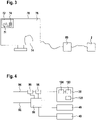
- Fig. 3 shows a schematic diagram of a digital microscope system 100 in accordance with an exemplary embodiment of the invention.
- the digital microscope system 100 comprises a digital microscope 2.
- the digital microscope 2 may be a digital microscope 2 having the mechanical set-up as described with respect to Fig. 1 above, the optical set-up as described with respect to Fig. 2 above, and the control set-up as will be described below with respect to Figs. 4 and 5 .
- the focus is on the user perspective and the user interaction with the digital microscope system 100.
- the digital microscope system 100 further comprises a computer 80, coupled to the digital microscope 2, and a screen 70, coupled to the computer 80.
- the computer 80 may be any kind of suitable processing device that provides for the interaction between the screen 70 and the digital microscope 2 in a suitable manner.
- the computer 80 may for example be a standard personal computer, embodied as a desktop computer or a laptop.
- the processing capacity, exemplarily provided by the computer 80 in the exemplary embodiment of Fig. 3 may also be embedded into the digital microscope 2 or into the screen 70.
- the screen 70 may for example be part of a tablet or a smartphone, having both the screen functionality and the processing functionality for interfacing directly with the digital microscope 2. It is also possible that the processing capacity, exemplarily provided by the computer 80 in the exemplary embodiment of Fig. 3 , may be provided on a remote processing device, such as a remote server as part of a cloud-based solution.
- the screen 70 is the control interface for the user of the digital microscope system 100.
- the screen 70 is a touch screen, so that the screen 70 provides both user input functionality and image output functionality.
- the user may control the whole operation of the digital microscope system 100 via the touch screen 70.
- other input devices are provided in addition / as an alternative to the touch screen 70.
- a keyboard and/or a mouse and/or any other suitable input device may be provided for the user to control the digital microscope system 100.
- multiple screens are provided for the output of images.
- images are output to other entities. For example, images may be saved to a hard drive or other data storage medium in file format.
- the screen 70 provides two different outputs.
- an image preview 72 is displayed in the upper left corner of the screen 70.
- the image preview 72 is an overview image of the sample that is arranged on the stage of the digital microscope 2.
- the overview image may be taken with an additional digital camera.
- the additional digital camera may be arranged next to the objective lens 24, i.e. it may be arranged with a viewing direction downwards onto the sample and arranged offset from the objective lens 24.
- the additional digital camera may be a low-quality, simple digital camera, with the sole purpose of providing a quick overview over the sample having sufficient detail to allow for a coarse navigation of the sample by the user.
- the image preview 72 may be generated in any other suitable manner as well. It is also possible that the image preview 72 is entirely dispensed with and that the user navigates through the sample without such an image preview 72.
- the sample is a biological sample.
- the sample comprises a cell culture 14, arranged on a clear slide.
- the sample comprises the cell culture 14, surrounded by empty space.
- the user may select an area of interest 74 in the image preview 72.
- the selection of the area of interest 74 is a user selection that determines the operation of the digital microscope and that determines what will be displayed on the screen 70. This will be explained in detail below.
- the user selection may be made in any suitable manner, such as with the user's fingers on the touch screen, with a suitable stylus, with an ancillary input device, such as a mouse, with menu-based selection tools, etc..
- an ancillary input device such as a mouse
- menu-based selection tools etc.
- the user selection contains an unambiguous determination, which portion of the sample is the area of interest for the user.
- the unambiguous determination may be in any form that allows for the derivation of the position and extension of the area of interest.
- the user selection as seen from the digital microscope system 100, may comprise the coordinates of the bottom left corner of the area of interest as well as the two-dimensional extension in the x-y coordinate system of the image preview 72.
- the user selection as seen from the digital microscope system 100, may comprise the coordinates of the top left corner and the bottom right corner of the area of interest.
- the user selection, as seen from the digital microscope system 100 may comprise a single coordinate, such as the center coordinate of the area of interest, and a zoom level as compared to the size of the entire sample.
- the digital microscope system 100 On the basis of the user selection, the digital microscope system 100 generates an assembled image, which corresponds to the area of interest 74 and which is displayed in the assembled image screen portion 76.
- the details of said generation of the assembled image from a system point of view will be described below with respect to Figs. 4 and 5 .
- the selection of the area of interest 74 results in an assembled image, which is highly magnified as compared to the image preview 72, in the assembled image screen portion 76, with the assembled image corresponding to the area of interest 74 of the sample.
- the term corresponding does not necessarily mean that the area of interest and the assembled image are perfectly congruent.
- the displayed assembled image shows a somewhat larger portion of the sample than the area of interest 74, such as for matching the dimensions of the screen 70.
- the assembled image screen portion 76 covers the entire screen 70, with the exception of the image preview 72. It is also possible that the user makes the user selection in the assembled image screen portion 76.
- the user may navigate the virtual representation of the sample, which may extend beyond the screen 70, via lateral translation and zooming operations.
- the user may use two-finger zooming commands, as are for example known from smartphone applications.
- the extension of the area of interest may also be referred to as a zoom level of the area of interest.
- a user selection comprising the position and the zoom level of the area of interest is therefore also an indication of the position and the extension of the area of interest.
- the image preview as taken by a low-quality additional camera, may be initially shown on the full screen, with the user navigating to the area of interest purely by lateral translation and zooming operations.
- Fig. 4 shows a block diagram of selected components of the digital microscope system 100 of Fig. 3 . While Fig 3 had its focus on the user front-end and the user interaction with the digital microscope system 100, the system side, including the hardware backend and the interposed control structure, are described with respect to Fig. 4 .
- the selected components depicted in Fig. 4 have two external connections, namely a user selection input 92 and as assembled image output 94. These two external connections may be seen as the interfaces to the touch screen 70 of Fig. 3 . While the user selection is communicated from the touch screen 70 to the components of the digital microscope system 100 of Fig. 4 via the user selection input 92, said components return the assembled image in suitably encoded form to the touch screen 7 for display on the assembled image screen portion 76 via the assembled image output 94.
- the digital camera 20 comprises an image sensor 120, a shutter 122, and an image sensor driver 124.
- the image sensor 120 captures image data, with the image sensor driver 124 reading out the captured image data from the image sensor 120.
- the digital microscope system 100 further comprises a control unit 90, an image data post-processing unit 96, and an image assembly unit 98.
- Each of the control unit 90, the image data post-processing unit 96, and the image assembly unit 98 may be provided in the digital microscope 2 or in the computer 80 or on a remote server. In the alternative, it is also possible that each of these components is provided in the screen 70.
- the control unit 90, the image data post-processing unit 96, and the image assembly unit 98 may be distributed among the digital microscope system 100. Further, each of the control unit 90, the image data post-processing unit 96, and the image assembly unit 98 may have hardware components or software components or mixed hardware and software components.
- the control unit 90, the image data post-processing unit 96, and the image assembly unit 98 are part of a software program that is run on the computer 80 and that is configured for controlling the digital microscope 2.
- the control unit 90 is coupled to the user selection input 92 for receiving the user selection regarding the area of interest of the sample.
- the control unit 90 is further coupled to the illumination assembly 40, to the stage drive assembly 46, and to the digital camera 20.
- the control unit is configured to control the illumination assembly 40, the stage drive assembly 46, and the digital camera 20, in particular the shutter 122 thereof and the image sensor driver 124 thereof, depending on the user selection.
- the control unit 90 is further coupled to the image data post-processing unit 96 and to the image assembly unit 98. Further, the digital camera 20 is coupled to the image data post-processing unit 96, which in turn is further coupled to the image assembly unit 98, which in turn is further coupled to the assembled image output 94. In this way, the control unit 90 is able to control the image processing chain downstream of the digital camera 20, as will be described below.
- the control unit 90 determines which individual images of the sample are generated, in order to generate an assembled image that corresponds to the area of interest, as indicated by the user selection.
- the image sensor 120 having a predefined number of image pixels and with the optical system of the digital microscope 2 having a set magnification, it is set by system parameters how big of a portion of the sample is translated into image data for an individual image.
- the size of the portion of the sample that can be captured with a one-time operation of the shutter 122 of the digital camera 120 is set. Given this set size, the control unit 90 determines on the basis of the position and extension of the area of interest, at which individual positions of the sample image data for individual images is captured.
- the individual positions for a row-wise or column-wise scan of the area of interest may be determined by the control unit 90.
- the control unit 90 then controls the stage drive assembly 46, the shutter 122, and the image sensor driver 124 in a synchronized manner to generate image data at the determined individual positions.
- the control unit 90 may control the illumination assembly 40 to provide continuous illumination or to provide intermittent illumination synchronized with the other components.
- the control unit 90 not only controls the positions at which image data for individual images is captured. On the basis of the user selection, the control unit 90 also determines whether a full resolution mode is used for generating the individual images or whether a reduced resolution mode is used for generating the individual images. In case a plurality of reduced resolution sub-modes are provided in the digital microscope system 100, the control unit selects one of the full resolution mode and the plurality of reduced resolution sub-modes for generating the individual images. In the exemplary embodiment described with respect to Fig. 4 , two reduced resolution sub-modes are provided in the digital microscope system 100, and the control unit 90 selects one of the three different modes for generating the individual images on the basis of the user selection.
- the image sensor 120 has a predefined number of image pixels.
- the individual images For the full resolution mode, the individual images have the predefined number of image pixels.
- the image sensor driver 124 reads out the predefined number of image pixels and the image post-processing unit 96 performs any desired kind of post-processing, such as color filtering or other filtering, on image data with the predefined number of image pixels.
- the individual images, as output by the image post-processing unit 96 have the predefined number of image pixels.
- the first way of reducing the number of image pixels is subsampling the predefined number of image pixels.
- the image sensor driver 124 is capable of subsampling the predefined number of image pixels of the image sensor.
- the image sensor driver 124 is able to read out a smaller number of image pixels than the predefined number of image pixels.
- the image sensor driver 124 may be capable of reading out image data for every other or every third or every fourth etc. image pixel, i.e. every n-th image pixel in general terms.
- the image sensor driver 124 may be capable to read out every n-th image pixel in both dimensions of the image sensor 124.
- the number of image pixels is reduced by a factor of 4.
- the number of image pixels is reduced by a factor of 9.
- Subsampling the predefined number of image pixels allows for speeding up the generation of the assembled image in a two-fold manner.
- a smaller amount of image data is provided downstream of the digital camera 20. In particular, a smaller amount of image data is provided to the image post-processing unit 96 and to the image assembly unit 98. The image processing operations, carried out in these downstream units of the digital camera 20, are carried out faster due to the lower number of image pixels.
- the second way of reducing the number of image pixels is down-scaling of image data captured by the image sensor 120.
- the image post-processing unit 96 is capable of down-scaling the image data captured by the image sensor 120.
- the term down-scaling refers to reducing the number of pixels by an image filtering operation.
- 4 pixels of a 2x2 pixel window may be replaced by a single pixel.
- the single replacement pixel may be the result of a comparably simple operation, such as an averaging of the 4 pixels in the 2x2 pixel window. In this way, the number of image pixels is reduced by factor of 4. This approach may be extended to larger pixel windows.
- the down-sampling of image data may be carried out at different points in the image processing chain.
- the down-sampling may be carried out right at the input of the image post-processing unit 96, i.e. right on the image data as received from the image sensor driver 124.
- the image post-processing unit 96 applies other image processing, before carrying out down-sampling.
- other image processing may be applied to the image data after down-sampling at the image post-processing unit 96.
- the down-sampling may be embedded into the image processing chain in such a way that the other image processing operations are applied to a larger number of pixels or a smaller number of pixels, depending what image size is desired for those other image processing operations.
- Down-sampling of image data allows for speeding up the generation of the assembled image, because all ensuing image processing operations after the down-sampling can be carried out faster due to the reduced number of image pixels.
- the ensuing image processing operations may comprise image processing on the individual image level in the image post-processing unit 96 and do comprise the assembly of the individual images in the image assembly unit 98.
- the assembled image data output may be provided faster and/or in a more easily processable size. Also, in case the assembled image data output is provided in a stepwise manner, the individual data packets may be provided in quicker succession and/or in a more easily processable size.
- the digital microscope system 100 of Fig. 4 has a full resolution mode and two reduced resolution sub-modes.
- the control unit 90 selects one of the full resolution mode and the two reduced resolution sub-modes.
- the control unit 90 further controls the image sensor driver 124 and the image post-processing unit 96 in accordance with the selected one of the full resolution mode and the two reduced resolution sub-modes.
- the control unit 90 controls the image sensor driver 124 to read out image data from the image sensor 120 for the full number of predefined image pixels. Further, the control unit 90 controls the image post-processing unit 96 to not carry out any down-sampling on the image data, as received from the image sensor driver 124.
- the image sensor having 1920 pixels x 1920 pixels
- the individual images also have 1920 pixels x 1920 pixels.
- the control unit 90 controls the image sensor driver 124 to read out image data from the image sensor 120 for every third pixel in each of the two dimensions. Further, the control unit 90 controls the image post-processing unit to carry out down-sampling by a factor of 2 for each of the two dimensions.
- the image sensor driver 124 provides image data for 640 pixels x 640 pixels to the image post-processing unit 96, and the individual images have 320 pixels x 320 pixels after down-sampling.
- the control unit 90 controls the image sensor driver 124 to read out image data from the image sensor 120 for every third pixel in each of the two dimensions. Further, the control unit 90 controls the image post-processing unit to carry out down-sampling by a factor of 10 for each of the two dimensions.
- the image sensor driver 124 provides image data for 640 pixels x 640 pixels to the image post-processing unit 96, and the individual images have 64 pixels x 64 pixels after down-sampling.
- the image assembly unit 98 is configured to assemble the individual images into the assembled image.
- the assembled image may be presented to the user on a screen, as shown in Fig. 3 , or saved into a file for viewing at a later point in time or provided to the user in any other suitable manner.
- the image assembly unit 98 may take different amounts of time to assemble the individual images. In particular, the image assembly unit 98 may require less time for smaller individual images.
- the image assembly unit 98 may assemble the individual images via any suitable procedure, such as via suitable stitching algorithms, which are per se known. For the stitching to have high quality, individual images may be generated with an overlap between neighbouring individual images.
- the control unit 90 selects the one of the full resolution mode and the first and second reduced resolution sub-modes on the basis of the extension of the area of interest, as selected by the user.
- the control unit 90 may have two area thresholds. If the area of interest is smaller than a first area threshold, the full resolution mode is selected. If the area of interest is bigger than the first area threshold, but smaller than a second area threshold, the first reduced resolution sub-mode is selected. If the area of interest is bigger then the second area threshold, the second reduced resolution sub-mode is selected.
- the rationale behind these thresholds is as follows. The smaller the area of interest, the more likely it is that the user is interested in the very details of the sample, hence a better image quality, i.e. a higher resolution of the individual images, is provided.
- control unit 90 may further be configured to control the stage drive assembly 46 and the shutter 122 depending on the user selection.
- the different modes may differ with the respect to the image sensor capturing image data while the stage is moving or while the stage is in a stopped position.
- the image data is captured by the image sensor 20, when the stage is in a stopped position.
- the image sensor 20 In this way, no blurriness due to the movement of the stage is introduced, and the image quality is optimized.
- subsequent individual images may be generated at a non-maximum speed.
- the operation times of the stage drive assembly may be the limiting factor in generating the individual images and the assembled image.
- the image data is captured by the image sensor 20, when the stage is moving.
- the stage may be moved with a first stage moving speed in the first reduced resolution sub-mode and with a second stage moving speed in the second reduced resolution sub-mode.
- the second stage moving speed is faster then the first stage moving speed.
- the subsampling allows for a quick reading out of image data and makes the image sensor ready for capturing new image data quickly. This quick readiness may be taken advantage of by capturing image data in quick succession during the movement of the stage.
- the stage moving speed and the level of subsampling may be adapted to each other, depending on the properties and constraints of the technical components involved.
- the first and second moving speeds may also be set in such a way that not more than an accepted level of blurriness is introduced into the assembled image.
- Various factors may be taken into account in this context. On the basis of the properties of the optical system and the physical pixel size in the image sensor, it may be determined what area of the sample relates to a pixel in the image sensor. Further, on the basis of the levels of subsampling and/or down-scaling, it may be determined what area of the sample relates to a pixel in the assembled image. Yet further, on the basis of the accepted level of blurriness in the assembled image, it may determined what maximum stage moving speed is acceptable for keeping the blurriness below the accepted level.
- the accepted level of blurriness may be defined in relation to the number of neighbouring pixels of the assembled image that are affected by a given point in the sample. For example, it may be set as a quality criterion that any given point in the sample may only affect two pixels in the assembled image. This is also referred to as a blurriness of 1 pixel, because any given point in the sample may affect at most one more pixel than in a case where the image data is captured with the stage stopped.
- the maximum stage moving speed may be set to the length of the area of the sample that relates to a pixel in the assembled image, divided by the shutter opening time for one image capturing operation by the image sensor.
- the maximum stage moving speed may also be set to the length of the area of the sample that relates to a pixel in the assembled image, divided by the total capturing and processing time for one image capturing operation by the digital camera 20. Potential further constraints in transporting the image data out of the image sensor 120 to a memory that can provide the image data for further processing independent of the real time may also be taken into account.
- the first and second stage moving speeds below the respective maximum stage moving speed as set for the particular operating scenarios of the first and second reduced resolution sub-modes, the blurriness of the assembled image may be kept at an accepted level, while allowing for a very quick provision of the assembled image.
- the desired pixel size of the assembled image is part of the user selection, as received by the control unit 90.
- the user selection may contain information on a desired resolution of the assembled image.
- the number of pixels of the screen 70 may be part of the information conveyed to the control unit 90.
- the control unit 90 may be configured to select one of the full resolution mode and the one or more reduced resolution (sub-)modes on the basis of the extension of the area of interest and the desired resolution of the assembled image.
- the control unit 90 may be configured to adapt the first and second area thresholds, as described above, depending on the desired resolution of the assembled image. In particular, the first and second area thresholds may be increased for higher desired resolutions. In this way, the quality of the assembled image may be adapted to the output medium and a high-quality assembled image may be presented to the user on the particular output medium used.
- the assembled image data may be displayed to the user in a stepwise manner.
- the image assembly unit 98 may carry out stitching of this individual image to the previously received individual images. This process may also be considered as a stitching of the newly received individual image to an already available portion of the assembled image.
- the stitching operation may alter the image data of the individual image and may therefore be seen as a filter operation.
- the filtered individual image may be provided to the screen and may be displayed together with the previously available portion of the assembled image, thus increasing the available, displayed portion of the assembled image.
- the user may experience this process as a stepwise building up of the assembled image.
- the efficiency of the user in analysing the sample may thus be increased.
- the display of the already available portion of the assembled image may put the user in a position to update the area of interest, e.g. via zooming in, before the whole assembled image is provided. It may also put the user in a position to find a particular feature he/she is looking for in the sample, before the whole assembled image is provided.
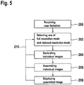
- Fig. 5 shows a flow chart of a method of providing an assembled image using a digital microscope in accordance with an exemplary embodiment of the invention.
- a user selection regarding an area of interest of the sample is received.
- one of a full resolution mode and a reduced resolution mode is selected.
- individual images of individual portions of the area of interest are generated at step 204.
- all or a subset of the illumination assembly, the stage drive assembly, the shutter of the digital camera, the image sensor driver of the digital camera, and the image post-processing unit are controlled in accordance with the selected mode.
- the individual images are assembled and the assembled image generated.
- the assembled image is displayed on a screen to the user.
- steps 204, 206, and 208 may be carried out in the depicted order. It is also possible that the steps 204, 206, and 208 are carried out in a partially parallel manner. As discussed above, the assembly of individual images and, potentially, also the display of the assembled image may already take place for a portion of the area of interest, while the individual images for another portion of the area of interest are still generated.
- the method may be configured to react to an updated user selection regarding an updated area of interest at any point throughout the method.
- the method may be configured to interpret the reception of an updated user selection as an interrupt and stop the step or steps presently being carried out.
- the method may interpret the updated user selection as an interrupt and may go back to step 202 on the basis of the updated user selection.
- This is indicated with the dashed line 210 in Fig. 5 , illustrating the receiving of the updated user selection, possible at any point throughout the method. It is possible that individual images, generated in the previous instance of step 204 and still relevant for the updated user selection, are re-used and not re-generated.
- the generation of the assembled image may be carried out very quickly for slight changes in the area of interest.
- the portion of the assembled image that still related to the updated area of interest and that was already generated in the previous instance of step 206 may be continued to be displayed on the screen. It may be supplemented with further portions of the assembled image of the updated area of interest in a stepwise manner. In this way, downtimes of the screen, which may interfere with the user's analysis due to him/her having to adapt to a fully new display on the screen, may be prevented.
Description
- The present invention is in the field of digital microscopy. In particular, the present invention is in the field of generating a digital image of a portion of a sample viewed via a digital microscope.
- Recent advances in technology aim at replacing conventional analog microscopes with digital microscopes. Current digital microscopes commonly operate in one of the following two operating modes. In one operating mode, the digital microscope is operated like a conventional analog microscope. The stage, holding the sample to be viewed, is driven to a desired location, and a single image is taken via the camera of the digital microscope, the single image corresponding to the position of the stage. The single image is presented to the user. In another operating mode, the user requests an image of the sample, and the microscope completes a row-wise or column-wise scan of the sample, assembling the image of the sample from the individual images taken during the scanning. These operating modes of current digital microscopes are not well-suited to all usage scenarios of digital microscopes.
-
DE 10 2007 033 793 A1 discloses a method for microscopic examination of a sample, in which an overview image of the sample composed of a large number of individual images is first recorded with a microscope in an overview mode and in which there is then a transition to a detail mode in which detailed images of areas of interest of the sample are recorded. The method is characterized in that the overview image is recorded in the overview mode with a lower resolution of the camera used than when the detailed images are recorded, and that the overview image and the detailed images are recorded with the same microscope objective. - It would be beneficial to provide a digital microscope system and a method of providing an assembled image using a digital microscope that allow for an improved handling by the user.
- Exemplary embodiments of the invention include a method of providing an assembled image using a digital microscope in accordance with claim 1, a digital microscope system in accordance with
claim 10, and a program for providing an assembled image using a digital microscope in accordance with claim 13. Further embodiments of the invention are given in the dependent claims. - Exemplary embodiments of the invention include a method of providing an assembled image using a digital microscope, the digital microscope having an optical system, an image sensor having a predefined number of image pixels, and a stage for holding a sample, the stage being movable in relation to the optical system and the image sensor, the method comprising receiving a user selection regarding an area of interest of the sample, the user selection indicating the position and extension of the area of interest; depending on the user selection, selecting one of a full resolution mode, wherein individual images with the predefined number of image pixels are generated, and a reduced resolution mode, wherein individual images with a reduced number of image pixels, as compared to the predefined number of image pixels, are generated; moving the stage with respect to the optical system and the image sensor, and generating individual images of the area of interest in accordance with the selected one of the full resolution mode and the reduced resolution mode; and combining the individual images into the assembled image, representing the area of interest.
- Exemplary embodiments of the invention allow for an adaptation of the generation of the individual images, which eventually combine to the assembled image, to the user selection regarding an area of interest of the sample. An image of that portion of the sample that the user is truly interested in may be provided with an optimised trade-off between image quality and speed of provision. In particular, by providing a selection between the full resolution mode and the reduced resolution mode for the generation of the individual images, the faster image processing of individual images with a reduced number of image pixels may be taken advantage of in case the user selection indicates that a comparably small resolution of the desired sample image is sufficient. For example, in case the user selection indicates that the user is interested in a rather large portion of the sample, i.e. in case the user selection indicates that the extension of the area of interest is rather large, the reduced resolution mode may be selected and the comparably large number of individual images, needed for generating a representation of said comparably large portion of the sample, may be achieved with superior speed, as compared to using the full resolution mode. In other words, based on the assumption that a user who is interested in a rather large portion of the sample is satisfied with a less than maximum resolution of the assembled image, the reduced resolution mode may be selected, thus improving the speed in generating the assembled image without compromising the user's needed resolution for the momentary use case. In case the user selection indicates a rather small area of interest, the full resolution mode may be selected. In that case, the comparably lower number of individual images, needed for generating the assembled image, may still be provided in a rather fast operation, and the user is provided with high image quality for the selected small area of interest.
- The digital microscope has an optical system. The optical system may be any kind of optical system suitable for providing the magnification desired for the digital microscope. In particular, the optical system may comprise an objective lens and a tubus lens. The magnification may be a set value due to the particular optical system arranged in the digital microscope. In particular, the magnification may be set due to the particular objective lens, arranged in the digital microscope.
- The digital microscope has a stage for holding a sample. The sample may be provided in the form of a slide. The slide may be positioned on the stage or may be introduced in a device designed specifically for holding slides.
- The stage is movable in relation to the optical system and the image sensor. In particular, the digital microscope may have a stage drive assembly that drives the stage with respect to the optical system and the image sensor. The optical system and the image sensor may be substantially stationary in the microscope frame of reference. The stage may be movable in two dimensions via the stage drive assembly, such that a two-dimensional scan of the sample may be carried out. The stage may further be movable towards/away from the optical system and the image sensor. This dimension of movement may be comparably small and may be provided for focusing purposes only.
- The digital microscope has an image sensor. The image sensor may be part of a digital camera. Accordingly, it may also be said that the digital microscope has a digital camera having an image sensor. The digital camera may have additional components commonly encountered in a camera, such as a shutter, an image sensor driver, etc.
- The method comprises receiving a user selection regarding an area of interest of the sample. The area of interest may also be described as a field of view that the user is interested in. This field of view may in particular be a field of view that the user wants to be displayed on a screen that cooperates with the digital microscope. The area of interest of the sample, which the user is interested in, corresponds to a particular portion of the stage, where said area of interest of the sample is located. Due to this correspondence between the area of interest of the sample and the corresponding portion of the stage, the stage may be moved in a manner to generate individual images of the area of interest.
- The term generating individual images of the area of interest refers to generating individual images of individual portions of the sample in the area of interest. The individual images may be generated in a scan of the area of interest. The individual images of neighbouring portions of the area of interest may have an overlap.
- The user selection indicates the position and extension of the area of interest. In particular, the user selection may implicitly specify the position and extension of the area of interest. For example, a user may make the user selection by zooming into and laterally navigating an image preview of the sample. Such zooming and laterally navigating may be done by a touch screen or via the operation of a mouse or via any other suitable input device. The position and the extension of the area of interest may result from the zooming and navigating with respect to the image preview. It is pointed out that the area of interest of the sample may be selected by the user in any suitable manner, as long as the method receives a user selection, the information of which may allow for a derivation of the position and extension of the area of interest.
- In the full resolution mode, individual images are generated with the predefined images of pixels. In contrast thereto, in the reduced resolution mode, individual images with a reduced number of image pixels are generated. The reduced number of image pixels allows for an image data processing of the individual images with enhanced speed. For example, any kind of post-processing filter, which may be applied to the image data of the individual images, may work faster with the reduced number of image pixels. Also, when combining the individual images into the assembled image, any stitching operation may work faster on individual images with the reduced number of image pixels. Accordingly, processing speed of image data may be traded off versus resolution of the assembled image, thus adapting the provision of the assembled image to the user selection. The convenience for the user may be improved in an adaptive manner, and the user's speed in analysing a sample may be enhanced.
- According to a further embodiment, the individual images with the reduced number of image pixels are generated by subsampling the predefined number of image pixels of the image sensor. Subsampling is a particularly efficient way of reducing the predefined number of image pixels of the individual images. In particular, subsampling reduces the number of image pixels right at the source, i.e. right at the image sensor such that all ensuing post-processing is carried out with the reduced number of image pixels. The term subsampling refers to reading out a reduced number of measurements from the image sensor, as compared to the full number of measurements available. In other words, subsampling refers to deliberately disregarding part of the image data that is generated at the image sensor. Subsampling may be done by reading out every n-th image pixel of the image sensor, such as every second or third of fourth image pixel, which subsampling may be applied to both dimensions of the image sensor. By applying subsampling, the read-out time for the image sensor may be reduced and the processing time of all ensuing image processing may be reduced. An increase in speed across the entire image processing chain may be achieved.
- According to a further embodiment, the individual images with the reduced number of image pixels are generated by down-scaling of image data generated by the image sensor. Down-scaling of image data is another way of reducing the number of image pixels. As compared to subsampling, as described above, all sensed image data is used. However, the image data for a given set of neighbouring pixels may be combined into a single pixel. For example, a single resulting pixel may be calculated from a window of 2x2 original pixels or 3x3 original pixels or 4x4 original pixels or 5x5 original pixels, etc.. In this way, the number of image pixels may be reduced, while basing the image data of the reduced number of image pixels on all information sensed by the image sensor. Down-scaling may generally be performed at any point in the image processing chain. It is possible to perform down-scaling of image data right after reading out the image data from the image sensor. In this way, the speed increase due to the reduced number of pixels may be taken advantage of over a large portion of the image processing chain. Down-scaling may be performed in accordance with any suitable down-scaling algorithm. Down-scaling algorithms are known per se to the skilled person.
- According to a further embodiment, the stage is moved in an at least partly continuous manner in the reduced resolution mode, with the image sensor capturing image data for the individual images when the stage is moving. In this way, the speed for generating the assembled image can be increased even further in the reduced resolution mode. With the image sensor capturing image data for the individual images when the stage is moving, no time-consuming start/stop operation of the stage is to be performed for capturing the image data for the individual images. Accordingly, the image data for the individual images are generated in quick succession, thus allowing for the full image data for the assembled image to be provided in a comparably very short time frame. The capturing of image data for the individual images during the movement of the stage is particularly beneficial in combination with the subsampling of the predefined number of image pixels of the image sensor. Because the subsampling allows for a faster read-out of the image data captured by the image sensor, the image sensor is quick in getting ready for capturing more image data. In this way, successive image capturing operations during movement of the stage can be achieved without creating any problems in terms of interfering with the read-out of the image sensor. The term at least partly continuous manner refers to a generally continuous motion, which may have stops at some positions. For example, there may be stops after a predefined number of image data capturing operations, in order to reach a well-defined starting point for all components of the digital microscope again. There may further be stops when changing the direction of the movement of the stage, such as when capturing a new row or new column of individual images. However, it is also possible that substantially all or all image data is captured when the stage is moving. It can also be said that at least the majority of image data for the individual images is captured when the stage is moving. This does not preclude some image data to be captured when the stage is stopped.
- According to a further embodiment, a moving speed of the stage is selected such that a blurring of the image data is restricted to at most two pixels, in particular to at most one pixel. In other words, the moving speed of the stage is selected such that each point of the sample affects at most three pixels, in particular at most two pixels, in the captured image data. In this way, the moving speed of the stage is adapted to the remainder of the system of the digital microscope. The moving speed of the stage and the level of blurring of image data is another dimension for trade-off between speed in provision of the assembled image and image quality. Accordingly, the handling of the digital microscope may again be adapted to the user selection. The term blurring of image data may refer to the level of blurring in the assembled image.
- According to a further embodiment, the stage is moved in an intermittent manner in the full-resolution mode with the image sensor capturing image data for the individual images when the stage is in a stopped position. In this way, the quality of the captured image data is particularly high, as there is no risk of blurring due to the movement of the stage, when capturing the image data. The terminology of moving a stage in an intermittent manner refers to a start/stop movement of the stage, which may also be referred to as a drive/stop movement of the stage. The stage drive assembly may be synchronized with the image sensor, in particular with the exposure times of the image sensor, in order to capture image data exactly at the point in time when the stage is in the stopped position.
- According to a further embodiment, the full resolution mode is selected if the extension of the area of interest is smaller than a first threshold. In order words, the full resolution mode is selected if the user is interested in a portion of the sample that is smaller than a threshold size. In this case, it is assumed that the user is interested in a high level of detail. Accordingly, a high resolution and, thus, a high image quality of the assembled image is selected. The first threshold may be a one-dimensional threshold, e.g. applied to the larger dimension of the area of interest, or may be a two-dimensional threshold or may be an area threshold.
- According to a further embodiment, the reduced resolution mode comprises a plurality of reduced resolution sub-modes and the step of selecting one of a full resolution mode and a reduced resolution mode comprises selecting one of the full resolution mode and the plurality of reduced resolution sub-modes. In this way, more than two modes of generating the individual images may be provided, thus enabling a more granular adaptation of the selected mode of generating individual images to the user needs. In particular, depending on the extension of the area of interest, a suitable one of the full resolution mode and the plurality of reduced resolution sub-modes may be selected. For this selection, a plurality of thresholds may be provided. Each of the thresholds may be a one-dimensional threshold or a two-dimensional threshold or an area threshold, as described above with respect to the first threshold.
- According to a further embodiment, each of the plurality of reduced resolution sub-modes has a respective sub-mode specific reduced number of image pixels for the individual images. In other words, the plurality of reduced resolution sub-modes differ with respect to each other with respect to the reduced number of image pixels. Each of the reduced resolution sub-modes has a different reduced number of image pixels for the individual images. The selection of the one of the full resolution mode and the plurality of reduced resolution sub-modes may be a monotonic function between the extension of the area of interest and the number of image pixels for the individual images in the respective modes. In other words, the smaller the extension of the area of interest, the higher the number of image pixels of the individual images may be.
- According to a further embodiment, the plurality of reduced resolution sub-modes differ in at least one of level of subsampling the predefined number of image pixels of the image sensor and a level of down-scaling of image data generated by the image sensor. In a particular embodiment, the plurality of reduced resolution sub-modes may differ in both the level of subsampling the predefined number of image pixels of the image sensor and the level of down-scaling of image data generated by the image sensor. It is also possible that the plurality of reduced resolution sub-modes differ with respect to the capturing of the image data being carried out when the stage is moved in an at least partly continuous manner or when the stage is in a stopped position in the course of an intermittent movement. Further, in case the image data is captured when the stage is moving, the plurality of reduced resolution sub-modes may differ with respect to the stage moving speed. In this way, the trade-off between speed of generation of individual images and, thus, the speed of generation of the assembled image and the quality of the assembled image may be adapted in a particularly granular manner for the plurality of reduced resolution sub-modes.
- According to a further embodiment, the plurality of reduced resolution sub-modes has two or three or four or five or six reduced resolution sub-modes. A larger number of reduced resolution sub-modes is possible as well.
- According to a further embodiment, the user selection further indicates a representation resolution indicative of a desired resolution of the assembled image. It is possible that the selection of the full resolution mode or the reduced resolution mode or one of the plurality of reduced resolution sub-modes, if applicable, may be based on the desired resolution by the user. In this way, the resulting assembled image may be more directly based on the user's wishes. It is also possible that the selection is based on the technical properties of the system around the digital microscope, such as the screen depicting the assembled image. In a particular embodiment, the representation resolution is indicative of a screen resolution of a screen for depicting the assembled image. In this way, the selection of the full resolution mode or the reduced resolution mode may allow for the provision of a high quality image, taking into account the screen resolution as well as the zoom level on the sample.
- According to a further embodiment, the method further comprises displaying the assembled image on a screen. In this way, the result of the method, as described above, is provided to the user in an intuitive manner. The displayed assembled image may form the basis for a further user selection, also referred to as updated user selection herein, such that the user may reach those areas of the sample that he/she is particularly interested in in an iterative manner.
- According to a further embodiment, the individual images are displayed on the screen in a stepwise manner. In particular, the individual images may be displayed on the screen, substantially as they become available after capturing the image data. In this way, the user may be provided with information for deciding on the next steps in the analysis of the sample even before the area of interest is fully displayed on the screen. From the perspective of the user, the assembled image is built up on the screen in a stepwise manner. The stepwise building of the assembled image may start in the middle of the area of interest and may move to the edges of the area of interest afterwards. It is also possible that the assembled image is built up in a row-wise or column-wise manner, potentially starting from a center line or from a center column. The building of the assembled image on the screen in a stepwise manner may be carried out to provide an intuitive reception of the assembled image on the part of the user and/or to convey a notion of speed to the user, thus making the handling of the digital microscope more convenient.
- According to a further embodiment, the method further comprises receiving an updated user selection regarding an updated area of interest of the sample, the updated user selection indicating the position and extension of the updated area of interest; interrupting the one or more method steps currently being carried out; depending on the updated user selection, re-selecting one of the full resolution mode and the reduced resolution mode; moving the stage with respect to the optical system and the image sensor, and generating individual images of the updated area of interest in accordance with the re-selected one of the full resolution mode and the reduced resolution mode; and combining the individual images into the assembled image, representing the updated area of interest. In this way, the method of providing the assembled image may immediately respond to the user's commands. It may be ensured that the updated area of interest is scanned and transformed into an assembled image without delay due to a previous instance of the method. Accordingly, the user receives the feedback of high responsiveness of the method and can work through the analysis of the sample in a particularly time-efficient manner.
- Exemplary embodiments of the invention further include a digital microscope system comprising an optical system; an image sensor having a predefined number of image pixels; a stage for holding a sample; a stage drive assembly for moving the stage in relation to the optical system and the image sensor; and a control unit for controlling generation of image data for an assembled image. The control unit is configured to: receive a user selection regarding an area of interest of the sample, the user selection indicating the position and extension of the area of interest; depending on the user selection, select one of a full resolution mode, wherein individual images with the predefined number of image pixels are generated, and a reduced resolution mode, wherein individual images with a reduced number of image pixels, as compared to the predefined number of image pixels, are generated; control the stage drive assembly to move the stage with respect to the optical system and the image sensor; and control the generation of individual images of the area of interest in accordance with the selected one of the full resolution mode and the reduced resolution mode. The additional features, modifications, and beneficial effects, as described above with respect to the method of providing an assembled image using a digital microscope, apply to the digital microscope system in an analogous manner. In particular, it is herewith explicitly disclosed that the control unit may be configured to carry out above-discussed method steps and/or may be configured to cause the component's of the digital microscope to carry out above-described method steps. The digital microscope system may be a digital microscope. It is also possible that the digital microscope system is a distributed system comprising a digital microscope and a data processing device, such as a computer, coupled thereto. The control unit may be provided in one of those entities or may be a distributed component among the digital microscope and the data processing device.
- According to a further embodiment, the control unit is configured to control the generation of individual images in the reduced resolution mode by causing at least one of subsampling the predefined number of image pixels of the image sensor and down-scaling of image data generated by the image sensor.
- According to a further embodiment, the control unit is configured to control the stage drive assembly to move the stage in an at least partly continuous manner in the reduced resolution mode and to control the image sensor to capture image data for the individual images when the stage is moving.
- The digital microscope may be a light microscope. It may have an illumination assembly arranged on the side of the stage that is distal from the optical system and the image sensor.
- Exemplary embodiments of the invention further include a program for providing an assembled image using a digital microscope, the digital microscope having an optical system, an image sensor having a predefined number of image pixels, and a stage for holding a sample, the stage being movable in relation to the optical system and the image sensor. The program comprises receiving a user selection regarding an area of interest of the sample, the user selection indicating the position and extension of the area of interest; depending on the user selection, selecting one of a full resolution mode and a reduced resolution mode; instructing the stage to move with respect to the optical system; instructing the image sensor to generate image data; on the basis of the image data, generating individual images of the area of interest with the predefined number of image pixels, if the full resolution mode is selected, and generating individual images of the area of interest with a reduced number of image pixels, if the reduced resolution mode is selected; and combining the individual images into the assembled image, representing the area of interest. The additional features, modifications, and beneficial effects as described above with respect to the method of providing an assembled image using a digital microscope, apply to the program for providing an assembled image using a digital microscope in an analogous manner.
- Further exemplary embodiments of the invention are described with respect to the accompanying drawings, wherein:
-
Fig. 1 shows a perspective view of a digital microscope in accordance with an exemplary embodiment of the invention; -
Fig. 2 shows a schematic diagram of selected components of the digital microscope ofFig. 1 ; -
Fig. 3 shows a schematic diagram of a digital microscope system in accordance with an exemplary embodiment of the invention, as seen from a user perspective; -
Fig. 4 shows a block diagram of selected components of the digital microscope system ofFig. 3 ; and -
Fig. 5 shows a flow chart of a method of providing an assembled image using a digital microscope in accordance with an exemplary embodiment of the invention. -
Fig. 1 shows adigital microscope 2 in accordance with an exemplary embodiment of the invention in a perspective, three-dimensional view. Thedigital microscope 2 has abase 4, which supports thedigital microscope 2. Thebase 4 may be placed on a table for providing a secure stand. - The
base 4 comprises an illumination assembly and a stage drive assembly, which are blocked from view by a base housing inFig. 1 and which will be described below. Astage 10 is mounted to thebase 4. The stage is movable with respect to thebase 4. In particular, thestage 10 is movable in two dimensions, referred to as x- and y-directions herein. In operation, thestage 10 is moved by the stage drive assembly in the x- and y-directions. - The
stage 10 has a transparent or translucent portion. A sample may be placed on the transparent or translucent portion. In the operating scenario depicted inFig. 1 , thesample 12 comprises two slides, arranged on the transparent or translucent portion of thestage 10 via a clipping mechanism. In operation, the illumination assembly illuminates thesample 12 from the bottom. The plane of the transparent or translucent portion of thestage 10 is referred to as the x-y-plane of the digital microscope. - The
digital microscope 2 further comprises asupport arm 6 and atube assembly 8. Thesupport arm 6 is shaped to support thetube assembly 8, such that thetube assembly 8 hovers over thestage 10. Thetube assembly 8 houses various optical components. In particular, thetube assembly 8 houses a digital camera and an optical system, which in turn has a tubus lens structure and anobjective lens 24 in the exemplary embodiment ofFig. 1 . While the digital camera and the tubus lens structure are blocked from view inFig. 1 by a tube assembly housing, theobjective lens 24 extends somewhat therefrom towards thestage 10. - The
tube assembly 8 is movable with respect to thesupport arm 6 in a moving direction orthogonal to the x-y-plane. In other words, thetube assembly 8 is movable in the z-direction of the microscope frame of reference. While this movement is quite limited, it is sufficient to bring thesample 12 in focus with respect to the optical system contained in thetube assembly 8. - In operation, the stage drive assembly brings the
stage 10 to desires positions in the x- and y-directions. The stage drive assembly may have any kind of suitable actuators, such as two small-scale electric motors for the two directions of movement. The illumination assembly provides for illumination of thesample 12 from underneath, and image data of that portion of thesample 12 placed in the way of light from the illumination assembly to the digital camera can be captured by the digital camera. The captured image data is referred to as as image data of an individual image herein, as it refers to image data corresponding to a singular position of thestage 10 and, thus, of thesample 12 with respect to the optical system and the digital camera. Via driving thestage 10 to various positions, multiple individual images may be generated. -
Fig. 2 shows selected components of thedigital microscope 2 ofFig. 1 in a schematic view. In particular,Fig. 2 illustrates the components relevant for the illumination of thesample 12 and the directing of light within thetube assembly 8. As described above, theillumination assembly 40 is arranged below thestage 10, i.e. below thesample 12, and directs lights upwards towards thesample 12. In the exemplary embodiment ofFig. 2 , theillumination assembly 40 has alight source 42 and acollimating lens 44 for directing a large amount of light towards that portion of thesample 12, whose image is captured. It is pointed out that theillumination assembly 40 may have any suitable set-up / design. - The
digital microscope 2 has anoptical system 25. In the exemplary embodiment ofFig. 2 , theoptical system 25 has atubus lens structure 22 and anobjective lens 24. Thetubus lens structure 22 hasindividual tubus lenses 23. The objective lens is provided for achieving a desired magnification of the portion of thesample 12 whose image is captured. In other words, the shape and design of theobjective lens 24 sets the magnification of thesample 12 for the resulting individual image. In the exemplary embodiment ofFig. 2 , theobjective lens 24 has a magnification of 20. - The
digital microscope 2 further has adigital camera 20. Thedigital camera 20 has an image sensor and a shutter. It may also have other components customary in the field of digital cameras, which may contribute to the operation of the digital camera capturing image data. Thetubus lens structure 22 directs the light, coming from theobjective lens 24, towards the image sensor of thedigital camera 20. In this way, alight path 50 from theillumination assembly 40 through thesample 12, through theobjective lens 24, through thetubus lens structure 22, and to the image sensor of thedigital camera 20 is established. -
Fig. 3 shows a schematic diagram of a digital microscope system 100 in accordance with an exemplary embodiment of the invention. The digital microscope system 100 comprises adigital microscope 2. Thedigital microscope 2 may be adigital microscope 2 having the mechanical set-up as described with respect toFig. 1 above, the optical set-up as described with respect toFig. 2 above, and the control set-up as will be described below with respect toFigs. 4 and5 . With respect toFig. 3 ,the focus is on the user perspective and the user interaction with the digital microscope system 100. - The digital microscope system 100 further comprises a
computer 80, coupled to thedigital microscope 2, and ascreen 70, coupled to thecomputer 80. Thecomputer 80 may be any kind of suitable processing device that provides for the interaction between thescreen 70 and thedigital microscope 2 in a suitable manner. Thecomputer 80 may for example be a standard personal computer, embodied as a desktop computer or a laptop. The processing capacity, exemplarily provided by thecomputer 80 in the exemplary embodiment ofFig. 3 , may also be embedded into thedigital microscope 2 or into thescreen 70. Thescreen 70 may for example be part of a tablet or a smartphone, having both the screen functionality and the processing functionality for interfacing directly with thedigital microscope 2. It is also possible that the processing capacity, exemplarily provided by thecomputer 80 in the exemplary embodiment ofFig. 3 , may be provided on a remote processing device, such as a remote server as part of a cloud-based solution. - The
screen 70 is the control interface for the user of the digital microscope system 100. In the exemplary embodiments ofFig. 3 , thescreen 70 is a touch screen, so that thescreen 70 provides both user input functionality and image output functionality. The user may control the whole operation of the digital microscope system 100 via thetouch screen 70. However, it is also possible that other input devices are provided in addition / as an alternative to thetouch screen 70. For example, a keyboard and/or a mouse and/or any other suitable input device may be provided for the user to control the digital microscope system 100. It is also possible that multiple screens are provided for the output of images. It is further possible that images are output to other entities. For example, images may be saved to a hard drive or other data storage medium in file format. - In the exemplary embodiment of
Fig. 3 , thescreen 70 provides two different outputs. In the upper left corner of thescreen 70, animage preview 72 is displayed. Theimage preview 72 is an overview image of the sample that is arranged on the stage of thedigital microscope 2. The overview image may be taken with an additional digital camera. The additional digital camera may be arranged next to theobjective lens 24, i.e. it may be arranged with a viewing direction downwards onto the sample and arranged offset from theobjective lens 24. The additional digital camera may be a low-quality, simple digital camera, with the sole purpose of providing a quick overview over the sample having sufficient detail to allow for a coarse navigation of the sample by the user. It is pointed out that theimage preview 72 may be generated in any other suitable manner as well. It is also possible that theimage preview 72 is entirely dispensed with and that the user navigates through the sample without such animage preview 72. - In the exemplary use case of
Fig. 3 , the sample is a biological sample. The sample comprises acell culture 14, arranged on a clear slide. Hence, from the user's perspective, the sample comprises thecell culture 14, surrounded by empty space. - In the exemplary embodiment of
Fig. 3 , the user may select an area ofinterest 74 in theimage preview 72. The selection of the area ofinterest 74 is a user selection that determines the operation of the digital microscope and that determines what will be displayed on thescreen 70. This will be explained in detail below. The user selection may be made in any suitable manner, such as with the user's fingers on the touch screen, with a suitable stylus, with an ancillary input device, such as a mouse, with menu-based selection tools, etc.. For the depicted use case, it is assumed that the user selected the area ofinterest 74 with his / her fingers on the touch screen in the portion of thescreen 70 where theimage preview 72 is depicted. The user selection is indicative of the position and extension of the area of interest. In other words, the user selection contains an unambiguous determination, which portion of the sample is the area of interest for the user. The unambiguous determination may be in any form that allows for the derivation of the position and extension of the area of interest. For example, the user selection, as seen from the digital microscope system 100, may comprise the coordinates of the bottom left corner of the area of interest as well as the two-dimensional extension in the x-y coordinate system of theimage preview 72. In another example, the user selection, as seen from the digital microscope system 100, may comprise the coordinates of the top left corner and the bottom right corner of the area of interest. In yet another example, the user selection, as seen from the digital microscope system 100, may comprise a single coordinate, such as the center coordinate of the area of interest, and a zoom level as compared to the size of the entire sample. - On the basis of the user selection, the digital microscope system 100 generates an assembled image, which corresponds to the area of
interest 74 and which is displayed in the assembledimage screen portion 76. The details of said generation of the assembled image from a system point of view will be described below with respect toFigs. 4 and5 . From the user point of view, the selection of the area ofinterest 74 results in an assembled image, which is highly magnified as compared to theimage preview 72, in the assembledimage screen portion 76, with the assembled image corresponding to the area ofinterest 74 of the sample. The term corresponding does not necessarily mean that the area of interest and the assembled image are perfectly congruent. For example, it is also possible that the displayed assembled image shows a somewhat larger portion of the sample than the area ofinterest 74, such as for matching the dimensions of thescreen 70. - In the exemplary embodiment of
Fig. 3 , the assembledimage screen portion 76 covers theentire screen 70, with the exception of theimage preview 72. It is also possible that the user makes the user selection in the assembledimage screen portion 76. For example, the user may navigate the virtual representation of the sample, which may extend beyond thescreen 70, via lateral translation and zooming operations. In a particular example, the user may use two-finger zooming commands, as are for example known from smartphone applications. The extension of the area of interest may also be referred to as a zoom level of the area of interest. A user selection comprising the position and the zoom level of the area of interest is therefore also an indication of the position and the extension of the area of interest. In a particular example, the image preview, as taken by a low-quality additional camera, may be initially shown on the full screen, with the user navigating to the area of interest purely by lateral translation and zooming operations. -
Fig. 4 shows a block diagram of selected components of the digital microscope system 100 ofFig. 3 . WhileFig 3 had its focus on the user front-end and the user interaction with the digital microscope system 100, the system side, including the hardware backend and the interposed control structure, are described with respect toFig. 4 . The selected components depicted inFig. 4 have two external connections, namely auser selection input 92 and as assembledimage output 94. These two external connections may be seen as the interfaces to thetouch screen 70 ofFig. 3 . While the user selection is communicated from thetouch screen 70 to the components of the digital microscope system 100 ofFig. 4 via theuser selection input 92, said components return the assembled image in suitably encoded form to the touch screen 7 for display on the assembledimage screen portion 76 via the assembledimage output 94. - As stated above, selected components of the digital microscope system 100 are depicted in
Fig. 4 . In particular, thedigital camera 20, theillumination assembly 40, and astage drive assembly 46, as already described above, are depicted inFig. 4 . Thedigital camera 20 comprises animage sensor 120, ashutter 122, and animage sensor driver 124. When theshutter 122 opens, theimage sensor 120 captures image data, with theimage sensor driver 124 reading out the captured image data from theimage sensor 120. - The digital microscope system 100 further comprises a
control unit 90, an imagedata post-processing unit 96, and animage assembly unit 98. Each of thecontrol unit 90, the imagedata post-processing unit 96, and theimage assembly unit 98 may be provided in thedigital microscope 2 or in thecomputer 80 or on a remote server. In the alternative, it is also possible that each of these components is provided in thescreen 70. Also, thecontrol unit 90, the imagedata post-processing unit 96, and theimage assembly unit 98 may be distributed among the digital microscope system 100. Further, each of thecontrol unit 90, the imagedata post-processing unit 96, and theimage assembly unit 98 may have hardware components or software components or mixed hardware and software components. In the exemplary embodiment ofFig. 4 , thecontrol unit 90, the imagedata post-processing unit 96, and theimage assembly unit 98 are part of a software program that is run on thecomputer 80 and that is configured for controlling thedigital microscope 2. - The
control unit 90 is coupled to theuser selection input 92 for receiving the user selection regarding the area of interest of the sample. Thecontrol unit 90 is further coupled to theillumination assembly 40, to thestage drive assembly 46, and to thedigital camera 20. The control unit is configured to control theillumination assembly 40, thestage drive assembly 46, and thedigital camera 20, in particular theshutter 122 thereof and theimage sensor driver 124 thereof, depending on the user selection. - The
control unit 90 is further coupled to the imagedata post-processing unit 96 and to theimage assembly unit 98. Further, thedigital camera 20 is coupled to the imagedata post-processing unit 96, which in turn is further coupled to theimage assembly unit 98, which in turn is further coupled to the assembledimage output 94. In this way, thecontrol unit 90 is able to control the image processing chain downstream of thedigital camera 20, as will be described below. - On the basis of the user selection, the
control unit 90 determines which individual images of the sample are generated, in order to generate an assembled image that corresponds to the area of interest, as indicated by the user selection. With theimage sensor 120 having a predefined number of image pixels and with the optical system of thedigital microscope 2 having a set magnification, it is set by system parameters how big of a portion of the sample is translated into image data for an individual image. In other words, the size of the portion of the sample that can be captured with a one-time operation of theshutter 122 of thedigital camera 120 is set. Given this set size, thecontrol unit 90 determines on the basis of the position and extension of the area of interest, at which individual positions of the sample image data for individual images is captured. For example, the individual positions for a row-wise or column-wise scan of the area of interest may be determined by thecontrol unit 90. Thecontrol unit 90 then controls thestage drive assembly 46, theshutter 122, and theimage sensor driver 124 in a synchronized manner to generate image data at the determined individual positions. Thecontrol unit 90 may control theillumination assembly 40 to provide continuous illumination or to provide intermittent illumination synchronized with the other components. - The
control unit 90 not only controls the positions at which image data for individual images is captured. On the basis of the user selection, thecontrol unit 90 also determines whether a full resolution mode is used for generating the individual images or whether a reduced resolution mode is used for generating the individual images. In case a plurality of reduced resolution sub-modes are provided in the digital microscope system 100, the control unit selects one of the full resolution mode and the plurality of reduced resolution sub-modes for generating the individual images. In the exemplary embodiment described with respect toFig. 4 , two reduced resolution sub-modes are provided in the digital microscope system 100, and thecontrol unit 90 selects one of the three different modes for generating the individual images on the basis of the user selection. - As stated above, the
image sensor 120 has a predefined number of image pixels. For the full resolution mode, the individual images have the predefined number of image pixels. Theimage sensor driver 124 reads out the predefined number of image pixels and theimage post-processing unit 96 performs any desired kind of post-processing, such as color filtering or other filtering, on image data with the predefined number of image pixels. The individual images, as output by theimage post-processing unit 96, have the predefined number of image pixels. - In the digital microscope system 100 of
Fig. 4 , there are two ways of reducing the number of image pixels for the one or more reduced resolution modes. The first way of reducing the number of image pixels is subsampling the predefined number of image pixels. In particular, theimage sensor driver 124 is capable of subsampling the predefined number of image pixels of the image sensor. In other words, theimage sensor driver 124 is able to read out a smaller number of image pixels than the predefined number of image pixels. For example, theimage sensor driver 124 may be capable of reading out image data for every other or every third or every fourth etc. image pixel, i.e. every n-th image pixel in general terms. In particular, theimage sensor driver 124 may be capable to read out every n-th image pixel in both dimensions of theimage sensor 124. For the exemplary case of image data for every second pixel being read out by theimage sensor driver 124, the number of image pixels is reduced by a factor of 4. For the exemplary case of image data for every third pixel being read out by theimage sensor driver 124, the number of image pixels is reduced by a factor of 9. - Subsampling the predefined number of image pixels allows for speeding up the generation of the assembled image in a two-fold manner. First, the reading out of image data from the
image sensor 120 is accelerated. In other words, a shorter amount of time is required for reading out the image data from theimage sensor 120 per individual image. In this way, theimage sensor 120 is ready for new image data more quickly, and image data for subsequent individual images can be captured in quicker succession. Hence, capturing of image data can be accelerated. Second, a smaller amount of image data is provided downstream of thedigital camera 20. In particular, a smaller amount of image data is provided to theimage post-processing unit 96 and to theimage assembly unit 98. The image processing operations, carried out in these downstream units of thedigital camera 20, are carried out faster due to the lower number of image pixels. - The second way of reducing the number of image pixels is down-scaling of image data captured by the
image sensor 120. In particular, theimage post-processing unit 96 is capable of down-scaling the image data captured by theimage sensor 120. The term down-scaling refers to reducing the number of pixels by an image filtering operation. In an exemplary case of down-scaling, 4 pixels of a 2x2 pixel window may be replaced by a single pixel. The single replacement pixel may be the result of a comparably simple operation, such as an averaging of the 4 pixels in the 2x2 pixel window. In this way, the number of image pixels is reduced by factor of 4. This approach may be extended to larger pixel windows. It is also possible that a more elaborate approach for calculating replacement pixels is employed. For example, larger image structures, such as contours, may be taken into account for calculating the replacement pixels. Down-sampling is per se known, and it is apparent to the skilled person that various down-sampling approaches may be used. - The down-sampling of image data may be carried out at different points in the image processing chain. For example, the down-sampling may be carried out right at the input of the
image post-processing unit 96, i.e. right on the image data as received from theimage sensor driver 124. It is also possible that theimage post-processing unit 96 applies other image processing, before carrying out down-sampling. Also, other image processing may be applied to the image data after down-sampling at theimage post-processing unit 96. The down-sampling may be embedded into the image processing chain in such a way that the other image processing operations are applied to a larger number of pixels or a smaller number of pixels, depending what image size is desired for those other image processing operations. - Down-sampling of image data allows for speeding up the generation of the assembled image, because all ensuing image processing operations after the down-sampling can be carried out faster due to the reduced number of image pixels. The ensuing image processing operations may comprise image processing on the individual image level in the
image post-processing unit 96 and do comprise the assembly of the individual images in theimage assembly unit 98. The assembled image data output may be provided faster and/or in a more easily processable size. Also, in case the assembled image data output is provided in a stepwise manner, the individual data packets may be provided in quicker succession and/or in a more easily processable size. - As pointed out above, the digital microscope system 100 of
Fig. 4 has a full resolution mode and two reduced resolution sub-modes. On the basis of the user selection, thecontrol unit 90 selects one of the full resolution mode and the two reduced resolution sub-modes. Thecontrol unit 90 further controls theimage sensor driver 124 and theimage post-processing unit 96 in accordance with the selected one of the full resolution mode and the two reduced resolution sub-modes. - According to the exemplary embodiment described with respect to
Fig. 4 , in the full resolution mode, thecontrol unit 90 controls theimage sensor driver 124 to read out image data from theimage sensor 120 for the full number of predefined image pixels. Further, thecontrol unit 90 controls theimage post-processing unit 96 to not carry out any down-sampling on the image data, as received from theimage sensor driver 124. For the exemplary case of the image sensor having 1920 pixels x 1920 pixels, the individual images also have 1920 pixels x 1920 pixels. - According to the exemplary embodiment described with respect to
Fig. 4 , in the first reduced resolution sub-mode, thecontrol unit 90 controls theimage sensor driver 124 to read out image data from theimage sensor 120 for every third pixel in each of the two dimensions. Further, thecontrol unit 90 controls the image post-processing unit to carry out down-sampling by a factor of 2 for each of the two dimensions. For the exemplary case of the image sensor having 1920 pixels x 1920 pixels, theimage sensor driver 124 provides image data for 640 pixels x 640 pixels to theimage post-processing unit 96, and the individual images have 320 pixels x 320 pixels after down-sampling. - According to the exemplary embodiment described with respect to
Fig. 4 , in the second reduced resolution sub-mode, thecontrol unit 90 controls theimage sensor driver 124 to read out image data from theimage sensor 120 for every third pixel in each of the two dimensions. Further, thecontrol unit 90 controls the image post-processing unit to carry out down-sampling by a factor of 10 for each of the two dimensions. For the exemplary case of the image sensor having 1920 pixels x 1920 pixels, theimage sensor driver 124 provides image data for 640 pixels x 640 pixels to theimage post-processing unit 96, and the individual images have 64 pixels x 64 pixels after down-sampling. - The
image assembly unit 98 is configured to assemble the individual images into the assembled image. The assembled image may be presented to the user on a screen, as shown inFig. 3 , or saved into a file for viewing at a later point in time or provided to the user in any other suitable manner. Given the different number of pixels for the individual images in the full resolution mode and the first and second reduced resolution sub-modes, theimage assembly unit 98 may take different amounts of time to assemble the individual images. In particular, theimage assembly unit 98 may require less time for smaller individual images. Theimage assembly unit 98 may assemble the individual images via any suitable procedure, such as via suitable stitching algorithms, which are per se known. For the stitching to have high quality, individual images may be generated with an overlap between neighbouring individual images. - In the exemplary embodiment of
Fig. 4 , thecontrol unit 90 selects the one of the full resolution mode and the first and second reduced resolution sub-modes on the basis of the extension of the area of interest, as selected by the user. In particular, thecontrol unit 90 may have two area thresholds. If the area of interest is smaller than a first area threshold, the full resolution mode is selected. If the area of interest is bigger than the first area threshold, but smaller than a second area threshold, the first reduced resolution sub-mode is selected. If the area of interest is bigger then the second area threshold, the second reduced resolution sub-mode is selected. The rationale behind these thresholds is as follows. The smaller the area of interest, the more likely it is that the user is interested in the very details of the sample, hence a better image quality, i.e. a higher resolution of the individual images, is provided. - Besides controlling the
image sensor driver 124 and theimage post-processing unit 96 in accordance with the user selection, thecontrol unit 90 may further be configured to control thestage drive assembly 46 and theshutter 122 depending on the user selection. In particular, there may be different stage movement patterns for the full resolution mode and the first and second reduced resolution sub-modes. In particular, the different modes may differ with the respect to the image sensor capturing image data while the stage is moving or while the stage is in a stopped position. - In the exemplary embodiment of
Fig. 4 , in the full resolution mode, the image data is captured by theimage sensor 20, when the stage is in a stopped position. In this way, no blurriness due to the movement of the stage is introduced, and the image quality is optimized. However, as the stage is stopped for every individual image, subsequent individual images may be generated at a non-maximum speed. The operation times of the stage drive assembly may be the limiting factor in generating the individual images and the assembled image. - In the exemplary embodiment of
Fig. 4 , in both the first reduced resolution sub-mode and the second reduced resolution sub-mode, the image data is captured by theimage sensor 20, when the stage is moving. In particular, the stage may be moved with a first stage moving speed in the first reduced resolution sub-mode and with a second stage moving speed in the second reduced resolution sub-mode. The second stage moving speed is faster then the first stage moving speed. By capturing image data during the movement of the stage, the image data for subsequent individual images can be captured in quicker succession, thus enabling a quicker generation of individual images and of the assembled image. The capturing of image data during the movement of the stage works particularly well with the subsampling of the predefined number of pixels by theimage sensor driver 124. As described above, the subsampling allows for a quick reading out of image data and makes the image sensor ready for capturing new image data quickly. This quick readiness may be taken advantage of by capturing image data in quick succession during the movement of the stage. The stage moving speed and the level of subsampling may be adapted to each other, depending on the properties and constraints of the technical components involved. - The first and second moving speeds may also be set in such a way that not more than an accepted level of blurriness is introduced into the assembled image. Various factors may be taken into account in this context. On the basis of the properties of the optical system and the physical pixel size in the image sensor, it may be determined what area of the sample relates to a pixel in the image sensor. Further, on the basis of the levels of subsampling and/or down-scaling, it may be determined what area of the sample relates to a pixel in the assembled image. Yet further, on the basis of the accepted level of blurriness in the assembled image, it may determined what maximum stage moving speed is acceptable for keeping the blurriness below the accepted level. The accepted level of blurriness may be defined in relation to the number of neighbouring pixels of the assembled image that are affected by a given point in the sample. For example, it may be set as a quality criterion that any given point in the sample may only affect two pixels in the assembled image. This is also referred to as a blurriness of 1 pixel, because any given point in the sample may affect at most one more pixel than in a case where the image data is captured with the stage stopped. On the basis of the accepted level of blurriness of 1 pixel, the maximum stage moving speed may be set to the length of the area of the sample that relates to a pixel in the assembled image, divided by the shutter opening time for one image capturing operation by the image sensor. In case the reading out operation of the captured image data is significant as compared to the shutter opening time, the maximum stage moving speed may also be set to the length of the area of the sample that relates to a pixel in the assembled image, divided by the total capturing and processing time for one image capturing operation by the
digital camera 20. Potential further constraints in transporting the image data out of theimage sensor 120 to a memory that can provide the image data for further processing independent of the real time may also be taken into account. By setting the first and second stage moving speeds below the respective maximum stage moving speed, as set for the particular operating scenarios of the first and second reduced resolution sub-modes, the blurriness of the assembled image may be kept at an accepted level, while allowing for a very quick provision of the assembled image. - It is further possible that the desired pixel size of the assembled image is part of the user selection, as received by the
control unit 90. In other words, the user selection may contain information on a desired resolution of the assembled image. For example, the number of pixels of thescreen 70 may be part of the information conveyed to thecontrol unit 90. Thecontrol unit 90 may be configured to select one of the full resolution mode and the one or more reduced resolution (sub-)modes on the basis of the extension of the area of interest and the desired resolution of the assembled image. For example, thecontrol unit 90 may be configured to adapt the first and second area thresholds, as described above, depending on the desired resolution of the assembled image. In particular, the first and second area thresholds may be increased for higher desired resolutions. In this way, the quality of the assembled image may be adapted to the output medium and a high-quality assembled image may be presented to the user on the particular output medium used. - In order to allow the user to already work on the portion of the assembled image that is already available, the assembled image data may be displayed to the user in a stepwise manner. For example, when a new individual image becomes available from the
image post-processing unit 96, theimage assembly unit 98 may carry out stitching of this individual image to the previously received individual images. This process may also be considered as a stitching of the newly received individual image to an already available portion of the assembled image. The stitching operation may alter the image data of the individual image and may therefore be seen as a filter operation. The filtered individual image may be provided to the screen and may be displayed together with the previously available portion of the assembled image, thus increasing the available, displayed portion of the assembled image. On the screen, the user may experience this process as a stepwise building up of the assembled image. The efficiency of the user in analysing the sample may thus be increased. For example, the display of the already available portion of the assembled image may put the user in a position to update the area of interest, e.g. via zooming in, before the whole assembled image is provided. It may also put the user in a position to find a particular feature he/she is looking for in the sample, before the whole assembled image is provided. -
Fig. 5 shows a flow chart of a method of providing an assembled image using a digital microscope in accordance with an exemplary embodiment of the invention. Atstep 200, a user selection regarding an area of interest of the sample is received. Atstep 202, based on the user selection received atstep 200, one of a full resolution mode and a reduced resolution mode, potentially one of a full resolution mode and a plurality of reduced resolution sub-modes, is selected. In accordance with the mode selected atstep 202, individual images of individual portions of the area of interest are generated atstep 204. For generating the individual images in accordance with the selected mode, all or a subset of the illumination assembly, the stage drive assembly, the shutter of the digital camera, the image sensor driver of the digital camera, and the image post-processing unit are controlled in accordance with the selected mode. Atstep 206, the individual images are assembled and the assembled image generated. Atstep 208, the assembled image is displayed on a screen to the user. - It is pointed out that the
steps steps - In the exemplary embodiment of
Fig. 5 , the method may be configured to react to an updated user selection regarding an updated area of interest at any point throughout the method. In particular, the method may be configured to interpret the reception of an updated user selection as an interrupt and stop the step or steps presently being carried out. The method may interpret the updated user selection as an interrupt and may go back to step 202 on the basis of the updated user selection. This is indicated with the dashedline 210 inFig. 5 , illustrating the receiving of the updated user selection, possible at any point throughout the method. It is possible that individual images, generated in the previous instance ofstep 204 and still relevant for the updated user selection, are re-used and not re-generated. In this way, the generation of the assembled image may be carried out very quickly for slight changes in the area of interest. Also, the portion of the assembled image that still related to the updated area of interest and that was already generated in the previous instance ofstep 206 may be continued to be displayed on the screen. It may be supplemented with further portions of the assembled image of the updated area of interest in a stepwise manner. In this way, downtimes of the screen, which may interfere with the user's analysis due to him/her having to adapt to a fully new display on the screen, may be prevented. - While the invention has been described with reference to exemplary embodiments, it will be understood by those skilled in the art that various changes may be made and equivalents may be substituted for elements thereof without departing from the scope of the invention. In addition, many modifications may be made to adapt a particular situation or material to the teachings of the invention without departing from the essential scope thereof. Therefore, it is intended that the invention not be limited to the particular embodiment disclosed, but that the invention will include all embodiments falling within the scope of the appended claims.
Claims (13)
- Method of providing an assembled image using a digital microscope (2), the digital microscope (2) having an optical system (25), an image sensor (120) having a predefined number of image pixels, and a stage (10) for holding a sample (12), the stage (10) being movable in relation to the optical system (25) and the image sensor (120), the method comprising:receiving a user selection regarding an area of interest (74) of the sample (12), the user selection indicating the position and extension of the area of interest (74),depending on the user selection, selecting one of a full resolution mode, wherein individual images with the predefined number of image pixels are generated, and a reduced resolution mode, wherein individual images with a reduced number of image pixels, as compared to the predefined number of image pixels, are generated,moving the stage (10) with respect to the optical system (25) and the image sensor (120), and generating individual images of the area of interest (74) in accordance with the selected one of the full resolution mode and the reduced resolution mode,combining the individual images into the assembled image, representing the area of interest (74), anddisplaying the assembled image on a screen (70), with the individual images being displayed on the screen (70) in a stepwise manner,wherein the method further comprises:receiving an updated user selection regarding an updated area of interest of the sample, the updated user selection indicating the position and extension of the updated area of interest, when the individual images are displayed on the screen in a stepwise manner,interrupting the one or more method steps currently being carried out, depending on the updated user selection, re-selecting one of the full resolution mode and the reduced resolution mode,moving the stage (10) with respect to the optical system and the image sensor, and generating individual images of the updated area of interest in accordance with the re-selected one of the full resolution mode and the reduced resolution mode, andcombining the individual images into the assembled image, representing the updated area of interest.
- Method according to claim 1, wherein the individual images with the reduced number of image pixels are generated by subsampling the predefined number of image pixels of the image sensor (120).
- Method according to claim 1 or 2, wherein the individual images with the reduced number of image pixels are generated by down-scaling of image data generated by the image sensor (120).
- Method according to any of the preceding claims, wherein the stage (10) is moved in an at least partly continuous manner in the reduced resolution mode, with the image sensor (120) capturing image data for the individual images when the stage is moving.
- Method according to claim 4, wherein a moving speed of the stage (10) is selected such that a blurring of the image data is restricted to at most 2 pixels, in particular to at most 1 pixel.
- Method according to any of the preceding claims, wherein the stage (10) is moved in an intermittent manner in the full resolution mode, with the image sensor (120) capturing image data for the individual images when the stage is in a stopped position.
- Method according to any of the preceding claims, wherein the reduced resolution mode comprises a plurality of reduced resolution sub-modes and wherein the step of selecting one of a full resolution mode and a reduced resolution mode comprises selecting one of the full resolution mode and the plurality of reduced resolution sub-modes.
- Method according to claim 7, wherein each of the plurality of reduced resolution sub-modes has a respective sub-mode specific reduced number of image pixels for the individual images, wherein the plurality of reduced resolution sub-modes in particular differ in at least one of a level of subsampling the predefined number of image pixels of the image sensor (120), and a level of down-scaling of image data generated by the image sensor (120).
- Method according to any of the preceding claims, wherein the user selection further indicates a representation resolution indicative of a desired resolution of the assembled image, wherein the representation resolution is in particular indicative of a screen resolution of a screen (70) for depicting the assembled image.
- Digital microscope system (100) comprising:an optical system (25),an image sensor (120) having a predefined number of image pixels,a stage (10) for holding a sample (12),a stage drive assembly (46) for moving the stage (10) in relation to the optical system (25) and the image sensor (120), anda control unit (90) for controlling generation of image data for an assembled image, wherein the control unit is configured to:- receive a user selection regarding an area of interest (74) of the sample (12), the user selection indicating the position and extension of the area of interest (74),- depending on the user selection, select one of a full resolution mode, wherein individual images with the predefined number of image pixels are generated, and a reduced resolution mode, wherein individual images with a reduced number of image pixels, as compared to the predefined number of image pixels, are generated,- control the stage drive assembly (46) to move the stage (10) with respect to the optical system (25) and the image sensor (120),- control the generation of individual images of the area of interest (74) in accordance with the selected one of the full resolution mode and the reduced resolution mode,- control the combination of the individual images into the assembled image, representing the area of interest (74), and- control a screen (70) to display the assembled image, with the individual images being displayed on the screen (70) in a stepwise manner,wherein the control unit is further configured to:- receive an updated user selection regarding an updated area of interest of the sample, the updated user selection indicating the position and extension of the updated area of interest, when the individual images are displayed on the screen in a stepwise manner,- interrupt the one or more steps currently being carried out,- depending on the updated user selection, re-select one of the full resolution mode and the reduced resolution mode,- control the stage drive assembly (46) to move the stage (10) with respect to the optical system (25) and the image sensor (120),- control the generation of individual images of the updated area of interest in accordance with the re-selected one of the full resolution mode and the reduced resolution mode, and- control the combination of the individual images into the assembled image, representing the updated area of interest.
- Digital microscope system (100) according to claim 10, wherein the control unit (90) is configured to control the generation of individual images in the reduced resolution mode by causing at least one of subsampling the predefined number of image pixels of the image sensor and down-scaling of image data generated by the image sensor.
- Digital microscope system (100) according to claim 10 or 11, wherein the control unit (90) is configured to control the stage drive assembly (46) to move the stage (10) in an at least partly continuous manner in the reduced resolution mode and to control the image sensor (120) to capture image data for the individual images when the stage is moving.
- Program for providing an assembled image using a digital microscope (2), the digital microscope (2) having an optical system (25), an image sensor (120) having a predefined number of image pixels, and a stage (10) for holding a sample (12), the stage (10) being movable in relation to the optical system (25) and the image sensor (120), the program comprising:receiving a user selection regarding an area of interest (74) of the sample (12), the user selection indicating the position and extension of the area of interest (74),depending on the user selection, selecting one of a full resolution mode and a reduced resolution mode,instructing the stage (10) to move with respect to the optical system (25),instructing the image sensor (120) to generate image data,on the basis of the image data, generating individual images of the area of interest (74) with the predefined number of image pixels, if the full resolution mode is selected, and generating individual images of the area of interest (74) with a reduced number of image pixels, if the reduced resolution mode is selected,combining the individual images into the assembled image, representing the area of interest (74), andinstructing a screen (70) to display the assembled image, with the individual images being displayed on the screen (70) in a stepwise manner,wherein the program further comprises:receiving an updated user selection regarding an updated area of interest of the sample, the updated user selection indicating the position and extension of the updated area of interest, when the individual images are displayed on the screen in a stepwise manner,interrupting the one or more steps currently being carried out,depending on the updated user selection, re-selecting one of the full resolution mode and the reduced resolution mode,instructing the stage (10) to move with respect to the optical system and the image sensor,instructing the image sensor (120) to generate image data,on the basis of the image data, generating individual images of the updated area of interest in accordance with the re-selected one of the full resolution mode and the reduced resolution mode, andcombining the individual images into the assembled image, representing the updated area of interest.
Priority Applications (7)
| Application Number | Priority Date | Filing Date | Title |
|---|---|---|---|
| EP22184451.7A EP4092469A1 (en) | 2019-11-15 | 2019-11-15 | Method of providing an assembled image using a digital microscope, digital microscope system, and program for providing an assembled image using a digital microscope |
| EP19209393.8A EP3822686B1 (en) | 2019-11-15 | 2019-11-15 | Method of providing an assembled image using a digital microscope, digital microscope system, and program for providing an assembled image using a digital microscope |
| CN202080078233.7A CN114730069A (en) | 2019-11-15 | 2020-11-13 | Method for providing combined image using digital microscope, digital microscope system, and program for providing combined image using digital microscope |
| PCT/EP2020/082067 WO2021094542A1 (en) | 2019-11-15 | 2020-11-13 | Method of providing an assembled image using a digital microscope, digital microscope system, and program for providing an assembled image using a digital microscope |
| US17/777,186 US20220404604A1 (en) | 2019-11-15 | 2020-11-13 | Method of providing an assembled image using a digital microscope, digital microscope system, and program for providing an assembled image using a digital microscope |
| JP2022527743A JP2023501589A (en) | 2019-11-15 | 2020-11-13 | Method of providing a composite image using a digital microscope, digital microscope system, and program for providing a composite image using a digital microscope |
| CA3158479A CA3158479A1 (en) | 2019-11-15 | 2020-11-13 | Method of providing an assembled image using a digital microscope, digital microscope system, and program for providing an assembled image using a digital microscope |
Applications Claiming Priority (1)
| Application Number | Priority Date | Filing Date | Title |
|---|---|---|---|
| EP19209393.8A EP3822686B1 (en) | 2019-11-15 | 2019-11-15 | Method of providing an assembled image using a digital microscope, digital microscope system, and program for providing an assembled image using a digital microscope |
Related Child Applications (1)
| Application Number | Title | Priority Date | Filing Date |
|---|---|---|---|
| EP22184451.7A Division EP4092469A1 (en) | 2019-11-15 | 2019-11-15 | Method of providing an assembled image using a digital microscope, digital microscope system, and program for providing an assembled image using a digital microscope |
Publications (2)
| Publication Number | Publication Date |
|---|---|
| EP3822686A1 EP3822686A1 (en) | 2021-05-19 |
| EP3822686B1 true EP3822686B1 (en) | 2022-08-03 |
Family
ID=68583163
Family Applications (2)
| Application Number | Title | Priority Date | Filing Date |
|---|---|---|---|
| EP22184451.7A Pending EP4092469A1 (en) | 2019-11-15 | 2019-11-15 | Method of providing an assembled image using a digital microscope, digital microscope system, and program for providing an assembled image using a digital microscope |
| EP19209393.8A Active EP3822686B1 (en) | 2019-11-15 | 2019-11-15 | Method of providing an assembled image using a digital microscope, digital microscope system, and program for providing an assembled image using a digital microscope |
Family Applications Before (1)
| Application Number | Title | Priority Date | Filing Date |
|---|---|---|---|
| EP22184451.7A Pending EP4092469A1 (en) | 2019-11-15 | 2019-11-15 | Method of providing an assembled image using a digital microscope, digital microscope system, and program for providing an assembled image using a digital microscope |
Country Status (6)
| Country | Link |
|---|---|
| US (1) | US20220404604A1 (en) |
| EP (2) | EP4092469A1 (en) |
| JP (1) | JP2023501589A (en) |
| CN (1) | CN114730069A (en) |
| CA (1) | CA3158479A1 (en) |
| WO (1) | WO2021094542A1 (en) |
Citations (11)
| Publication number | Priority date | Publication date | Assignee | Title |
|---|---|---|---|---|
| WO1998044446A1 (en) | 1997-03-03 | 1998-10-08 | Bacus Research Laboratories, Inc. | Method and apparatus for acquiring and reconstructing magnified specimen images from a computer-controlled microscope |
| US20030016301A1 (en) | 2000-02-04 | 2003-01-23 | Olympus Optical Co., Ltd. | Microscope system |
| US20030210262A1 (en) | 2002-05-10 | 2003-11-13 | Tripath Imaging, Inc. | Video microscopy system and multi-view virtual slide viewer capable of simultaneously acquiring and displaying various digital views of an area of interest located on a microscopic slide |
| WO2006028439A1 (en) | 2004-09-01 | 2006-03-16 | Aperio Technologies, Inc. | System and method for data management in a linear-array-based microscope slide scanner |
| DE102007033793A1 (en) | 2007-07-19 | 2009-01-22 | Carl Zeiss Imaging Solutions Gmbh | Method and apparatus for microscopically examining a sample, computer program and computer program product |
| JP2009025362A (en) | 2007-07-17 | 2009-02-05 | Nikon Corp | Microscopic image pickup apparatus and microscope system |
| DE102016107272A1 (en) | 2016-04-20 | 2017-10-26 | Beckhoff Automation Gmbh | Concept for checking an object |
| WO2017211584A1 (en) | 2016-06-06 | 2017-12-14 | Carl Zeiss Microscopy Gmbh | Digital microscope having an objective and having an image sensor |
| WO2017215707A2 (en) | 2016-06-15 | 2017-12-21 | Sensovation Ag | Method for digitally collecting a sample by a microscope |
| WO2018134129A1 (en) | 2017-01-23 | 2018-07-26 | Carl Zeiss Microscopy Gmbh | Microscope and method for viewing a specimen using a microscope |
| DE102018104704A1 (en) | 2018-03-01 | 2019-09-05 | Carl Zeiss Microscopy Gmbh | Digital microscope and method for changing a magnification of a digital microscope |
Family Cites Families (2)
| Publication number | Priority date | Publication date | Assignee | Title |
|---|---|---|---|---|
| JP6069825B2 (en) * | 2011-11-18 | 2017-02-01 | ソニー株式会社 | Image acquisition apparatus, image acquisition method, and image acquisition program |
| JP6325815B2 (en) * | 2013-12-27 | 2018-05-16 | 株式会社キーエンス | Magnification observation apparatus, magnification image observation method, magnification image observation program, and computer-readable recording medium |
-
2019
- 2019-11-15 EP EP22184451.7A patent/EP4092469A1/en active Pending
- 2019-11-15 EP EP19209393.8A patent/EP3822686B1/en active Active
-
2020
- 2020-11-13 CN CN202080078233.7A patent/CN114730069A/en active Pending
- 2020-11-13 CA CA3158479A patent/CA3158479A1/en active Pending
- 2020-11-13 JP JP2022527743A patent/JP2023501589A/en active Pending
- 2020-11-13 US US17/777,186 patent/US20220404604A1/en active Pending
- 2020-11-13 WO PCT/EP2020/082067 patent/WO2021094542A1/en active Application Filing
Patent Citations (12)
| Publication number | Priority date | Publication date | Assignee | Title |
|---|---|---|---|---|
| WO1998044446A1 (en) | 1997-03-03 | 1998-10-08 | Bacus Research Laboratories, Inc. | Method and apparatus for acquiring and reconstructing magnified specimen images from a computer-controlled microscope |
| US6522774B1 (en) | 1997-03-03 | 2003-02-18 | Bacus Research Laboratories, Inc. | Method and apparatus for creating a virtual microscope slide |
| US20030016301A1 (en) | 2000-02-04 | 2003-01-23 | Olympus Optical Co., Ltd. | Microscope system |
| US20030210262A1 (en) | 2002-05-10 | 2003-11-13 | Tripath Imaging, Inc. | Video microscopy system and multi-view virtual slide viewer capable of simultaneously acquiring and displaying various digital views of an area of interest located on a microscopic slide |
| WO2006028439A1 (en) | 2004-09-01 | 2006-03-16 | Aperio Technologies, Inc. | System and method for data management in a linear-array-based microscope slide scanner |
| JP2009025362A (en) | 2007-07-17 | 2009-02-05 | Nikon Corp | Microscopic image pickup apparatus and microscope system |
| DE102007033793A1 (en) | 2007-07-19 | 2009-01-22 | Carl Zeiss Imaging Solutions Gmbh | Method and apparatus for microscopically examining a sample, computer program and computer program product |
| DE102016107272A1 (en) | 2016-04-20 | 2017-10-26 | Beckhoff Automation Gmbh | Concept for checking an object |
| WO2017211584A1 (en) | 2016-06-06 | 2017-12-14 | Carl Zeiss Microscopy Gmbh | Digital microscope having an objective and having an image sensor |
| WO2017215707A2 (en) | 2016-06-15 | 2017-12-21 | Sensovation Ag | Method for digitally collecting a sample by a microscope |
| WO2018134129A1 (en) | 2017-01-23 | 2018-07-26 | Carl Zeiss Microscopy Gmbh | Microscope and method for viewing a specimen using a microscope |
| DE102018104704A1 (en) | 2018-03-01 | 2019-09-05 | Carl Zeiss Microscopy Gmbh | Digital microscope and method for changing a magnification of a digital microscope |
Non-Patent Citations (4)
| Title |
|---|
| "Digital Microscope & Scanner - PreciPoint M8", YOUTUBE, 3 June 2017 (2017-06-03), Retrieved from the Internet <URL:https://www.youtube.com/watch?v=blBm4qX8JBs> |
| MEDLINEUK: "Precipoint M8 Digital Microscope & Scanner", YOUTUBE, XP093151872, Retrieved from the Internet <URL:https://www.youtube.com/watch?v=OrIvMqeHEW0> [retrieved on 20240415] |
| PRECIPOINT GMBH: "PreciPoint M8 InstantScan Mode - a revolutionary improvement to virtual microscopy", YOUTUBE, XP093151864, Retrieved from the Internet <URL:https://www.youtube.com/watch?v=JVKojIzE4tk> [retrieved on 20240415] |
| ROBERT MEYER: "PreciPoint M8 Remote Contol Scanner-Microscope for Frozen Sections", YOUTUBE, XP093151871, Retrieved from the Internet <URL:https://www.youtube.com/watch?v=hi7XifyGgVY> [retrieved on 20240415] |
Also Published As
| Publication number | Publication date |
|---|---|
| EP3822686A1 (en) | 2021-05-19 |
| CN114730069A (en) | 2022-07-08 |
| CA3158479A1 (en) | 2021-05-20 |
| EP4092469A1 (en) | 2022-11-23 |
| US20220404604A1 (en) | 2022-12-22 |
| WO2021094542A1 (en) | 2021-05-20 |
| JP2023501589A (en) | 2023-01-18 |
Similar Documents
| Publication | Publication Date | Title |
|---|---|---|
| CN109889708B (en) | Dual aperture zoom digital camera with automatically adjustable tele field of view | |
| US9851550B2 (en) | Fully automatic rapid microscope slide scanner | |
| US9151942B2 (en) | Microscope system | |
| US20100194873A1 (en) | Method and device for microscopically examining a sample, computer program and computer program product | |
| US20120044342A1 (en) | Digital microscope | |
| US7864414B2 (en) | Microscope and virtual slide forming system | |
| US20070081231A1 (en) | Microscope apparatus and microscope system | |
| CN111788508B (en) | Digital microscope and method for changing the magnification of a digital microscope | |
| US20050002587A1 (en) | Microscope system | |
| CN103686270A (en) | Image viewing method based on user interaction input and related image viewing system | |
| JP2007017930A (en) | Microscopic device | |
| US7986338B2 (en) | Microscope system and image production method | |
| JP4653041B2 (en) | System and method for synthesizing image blocks and creating a seamless enlarged image of a microscope slide | |
| EP3822686B1 (en) | Method of providing an assembled image using a digital microscope, digital microscope system, and program for providing an assembled image using a digital microscope | |
| JP2007034050A (en) | Observation apparatus and control method thereof | |
| JP2005266718A (en) | Microscopic image photographing system | |
| EP4067965A1 (en) | Method of providing an assembled image using a digital microscope, digital microscope system, and program for providing an assembled image using a digital microscope | |
| JP2004177782A (en) | Magnification observation apparatus, magnified image observation method, magnification observation apparatus operating program, and computer readable recording medium | |
| JP2007316993A (en) | Image processor, method for selecting image data, and program for making computer execute the method | |
| US20240053596A1 (en) | Control device for a microscope | |
| EP4113324A1 (en) | Method for generating an image file archive, method for providing a microscopic image in an image file archive, method for restoring a partial image from an image file archive, and image file archive | |
| US11734936B2 (en) | Digital microscope system, method for operating the same and computer program | |
| JP5102081B2 (en) | Microscope device, drive control device thereof, program | |
| JP2019078904A (en) | Microscope system |
Legal Events
| Date | Code | Title | Description |
|---|---|---|---|
| PUAI | Public reference made under article 153(3) epc to a published international application that has entered the european phase |
Free format text: ORIGINAL CODE: 0009012 |
|
| STAA | Information on the status of an ep patent application or granted ep patent |
Free format text: STATUS: THE APPLICATION HAS BEEN PUBLISHED |
|
| AK | Designated contracting states |
Kind code of ref document: A1 Designated state(s): AL AT BE BG CH CY CZ DE DK EE ES FI FR GB GR HR HU IE IS IT LI LT LU LV MC MK MT NL NO PL PT RO RS SE SI SK SM TR |
|
| STAA | Information on the status of an ep patent application or granted ep patent |
Free format text: STATUS: REQUEST FOR EXAMINATION WAS MADE |
|
| 17P | Request for examination filed |
Effective date: 20211118 |
|
| RBV | Designated contracting states (corrected) |
Designated state(s): AL AT BE BG CH CY CZ DE DK EE ES FI FR GB GR HR HU IE IS IT LI LT LU LV MC MK MT NL NO PL PT RO RS SE SI SK SM TR |
|
| GRAP | Despatch of communication of intention to grant a patent |
Free format text: ORIGINAL CODE: EPIDOSNIGR1 |
|
| STAA | Information on the status of an ep patent application or granted ep patent |
Free format text: STATUS: GRANT OF PATENT IS INTENDED |
|
| INTG | Intention to grant announced |
Effective date: 20220216 |
|
| GRAS | Grant fee paid |
Free format text: ORIGINAL CODE: EPIDOSNIGR3 |
|
| GRAA | (expected) grant |
Free format text: ORIGINAL CODE: 0009210 |
|
| STAA | Information on the status of an ep patent application or granted ep patent |
Free format text: STATUS: THE PATENT HAS BEEN GRANTED |
|
| AK | Designated contracting states |
Kind code of ref document: B1 Designated state(s): AL AT BE BG CH CY CZ DE DK EE ES FI FR GB GR HR HU IE IS IT LI LT LU LV MC MK MT NL NO PL PT RO RS SE SI SK SM TR |
|
| REG | Reference to a national code |
Ref country code: AT Ref legal event code: REF Ref document number: 1509214 Country of ref document: AT Kind code of ref document: T Effective date: 20220815 Ref country code: CH Ref legal event code: EP |
|
| REG | Reference to a national code |
Ref country code: DE Ref legal event code: R096 Ref document number: 602019017721 Country of ref document: DE |
|
| REG | Reference to a national code |
Ref country code: IE Ref legal event code: FG4D |
|
| REG | Reference to a national code |
Ref country code: NL Ref legal event code: FP |
|
| REG | Reference to a national code |
Ref country code: LT Ref legal event code: MG9D |
|
| PG25 | Lapsed in a contracting state [announced via postgrant information from national office to epo] |
Ref country code: SE Free format text: LAPSE BECAUSE OF FAILURE TO SUBMIT A TRANSLATION OF THE DESCRIPTION OR TO PAY THE FEE WITHIN THE PRESCRIBED TIME-LIMIT Effective date: 20220803 Ref country code: RS Free format text: LAPSE BECAUSE OF FAILURE TO SUBMIT A TRANSLATION OF THE DESCRIPTION OR TO PAY THE FEE WITHIN THE PRESCRIBED TIME-LIMIT Effective date: 20220803 Ref country code: PT Free format text: LAPSE BECAUSE OF FAILURE TO SUBMIT A TRANSLATION OF THE DESCRIPTION OR TO PAY THE FEE WITHIN THE PRESCRIBED TIME-LIMIT Effective date: 20221205 Ref country code: NO Free format text: LAPSE BECAUSE OF FAILURE TO SUBMIT A TRANSLATION OF THE DESCRIPTION OR TO PAY THE FEE WITHIN THE PRESCRIBED TIME-LIMIT Effective date: 20221103 Ref country code: LV Free format text: LAPSE BECAUSE OF FAILURE TO SUBMIT A TRANSLATION OF THE DESCRIPTION OR TO PAY THE FEE WITHIN THE PRESCRIBED TIME-LIMIT Effective date: 20220803 Ref country code: LT Free format text: LAPSE BECAUSE OF FAILURE TO SUBMIT A TRANSLATION OF THE DESCRIPTION OR TO PAY THE FEE WITHIN THE PRESCRIBED TIME-LIMIT Effective date: 20220803 Ref country code: FI Free format text: LAPSE BECAUSE OF FAILURE TO SUBMIT A TRANSLATION OF THE DESCRIPTION OR TO PAY THE FEE WITHIN THE PRESCRIBED TIME-LIMIT Effective date: 20220803 Ref country code: ES Free format text: LAPSE BECAUSE OF FAILURE TO SUBMIT A TRANSLATION OF THE DESCRIPTION OR TO PAY THE FEE WITHIN THE PRESCRIBED TIME-LIMIT Effective date: 20220803 |
|
| REG | Reference to a national code |
Ref country code: AT Ref legal event code: MK05 Ref document number: 1509214 Country of ref document: AT Kind code of ref document: T Effective date: 20220803 |
|
| PG25 | Lapsed in a contracting state [announced via postgrant information from national office to epo] |
Ref country code: PL Free format text: LAPSE BECAUSE OF FAILURE TO SUBMIT A TRANSLATION OF THE DESCRIPTION OR TO PAY THE FEE WITHIN THE PRESCRIBED TIME-LIMIT Effective date: 20220803 Ref country code: IS Free format text: LAPSE BECAUSE OF FAILURE TO SUBMIT A TRANSLATION OF THE DESCRIPTION OR TO PAY THE FEE WITHIN THE PRESCRIBED TIME-LIMIT Effective date: 20221203 Ref country code: HR Free format text: LAPSE BECAUSE OF FAILURE TO SUBMIT A TRANSLATION OF THE DESCRIPTION OR TO PAY THE FEE WITHIN THE PRESCRIBED TIME-LIMIT Effective date: 20220803 Ref country code: GR Free format text: LAPSE BECAUSE OF FAILURE TO SUBMIT A TRANSLATION OF THE DESCRIPTION OR TO PAY THE FEE WITHIN THE PRESCRIBED TIME-LIMIT Effective date: 20221104 |
|
| REG | Reference to a national code |
Ref country code: DE Ref legal event code: R026 Ref document number: 602019017721 Country of ref document: DE |
|
| PG25 | Lapsed in a contracting state [announced via postgrant information from national office to epo] |
Ref country code: SM Free format text: LAPSE BECAUSE OF FAILURE TO SUBMIT A TRANSLATION OF THE DESCRIPTION OR TO PAY THE FEE WITHIN THE PRESCRIBED TIME-LIMIT Effective date: 20220803 Ref country code: RO Free format text: LAPSE BECAUSE OF FAILURE TO SUBMIT A TRANSLATION OF THE DESCRIPTION OR TO PAY THE FEE WITHIN THE PRESCRIBED TIME-LIMIT Effective date: 20220803 Ref country code: DK Free format text: LAPSE BECAUSE OF FAILURE TO SUBMIT A TRANSLATION OF THE DESCRIPTION OR TO PAY THE FEE WITHIN THE PRESCRIBED TIME-LIMIT Effective date: 20220803 Ref country code: CZ Free format text: LAPSE BECAUSE OF FAILURE TO SUBMIT A TRANSLATION OF THE DESCRIPTION OR TO PAY THE FEE WITHIN THE PRESCRIBED TIME-LIMIT Effective date: 20220803 Ref country code: AT Free format text: LAPSE BECAUSE OF FAILURE TO SUBMIT A TRANSLATION OF THE DESCRIPTION OR TO PAY THE FEE WITHIN THE PRESCRIBED TIME-LIMIT Effective date: 20220803 |
|
| PGFP | Annual fee paid to national office [announced via postgrant information from national office to epo] |
Ref country code: CH Payment date: 20230103 Year of fee payment: 4 |
|
| PLBI | Opposition filed |
Free format text: ORIGINAL CODE: 0009260 |
|
| PLAX | Notice of opposition and request to file observation + time limit sent |
Free format text: ORIGINAL CODE: EPIDOSNOBS2 |
|
| 26 | Opposition filed |
Opponent name: ARGOS SLIDE SCANNER SYSTEMS GMBH & CO. KG Effective date: 20230426 |
|
| PG25 | Lapsed in a contracting state [announced via postgrant information from national office to epo] |
Ref country code: SK Free format text: LAPSE BECAUSE OF FAILURE TO SUBMIT A TRANSLATION OF THE DESCRIPTION OR TO PAY THE FEE WITHIN THE PRESCRIBED TIME-LIMIT Effective date: 20220803 Ref country code: EE Free format text: LAPSE BECAUSE OF FAILURE TO SUBMIT A TRANSLATION OF THE DESCRIPTION OR TO PAY THE FEE WITHIN THE PRESCRIBED TIME-LIMIT Effective date: 20220803 |
|
| PGFP | Annual fee paid to national office [announced via postgrant information from national office to epo] |
Ref country code: DE Payment date: 20230124 Year of fee payment: 4 |
|
| PG25 | Lapsed in a contracting state [announced via postgrant information from national office to epo] |
Ref country code: MC Free format text: LAPSE BECAUSE OF FAILURE TO SUBMIT A TRANSLATION OF THE DESCRIPTION OR TO PAY THE FEE WITHIN THE PRESCRIBED TIME-LIMIT Effective date: 20220803 Ref country code: AL Free format text: LAPSE BECAUSE OF FAILURE TO SUBMIT A TRANSLATION OF THE DESCRIPTION OR TO PAY THE FEE WITHIN THE PRESCRIBED TIME-LIMIT Effective date: 20220803 |
|
| P01 | Opt-out of the competence of the unified patent court (upc) registered |
Effective date: 20230525 |
|
| REG | Reference to a national code |
Ref country code: BE Ref legal event code: MM Effective date: 20221130 |
|
| PG25 | Lapsed in a contracting state [announced via postgrant information from national office to epo] |
Ref country code: SI Free format text: LAPSE BECAUSE OF FAILURE TO SUBMIT A TRANSLATION OF THE DESCRIPTION OR TO PAY THE FEE WITHIN THE PRESCRIBED TIME-LIMIT Effective date: 20220803 Ref country code: LU Free format text: LAPSE BECAUSE OF NON-PAYMENT OF DUE FEES Effective date: 20221115 |
|
| PLBB | Reply of patent proprietor to notice(s) of opposition received |
Free format text: ORIGINAL CODE: EPIDOSNOBS3 |
|
| PG25 | Lapsed in a contracting state [announced via postgrant information from national office to epo] |
Ref country code: BE Free format text: LAPSE BECAUSE OF NON-PAYMENT OF DUE FEES Effective date: 20221130 |
|
| PGFP | Annual fee paid to national office [announced via postgrant information from national office to epo] |
Ref country code: GB Payment date: 20231220 Year of fee payment: 5 |
|
| PGFP | Annual fee paid to national office [announced via postgrant information from national office to epo] |
Ref country code: NL Payment date: 20231129 Year of fee payment: 5 Ref country code: IE Payment date: 20231128 Year of fee payment: 5 Ref country code: FR Payment date: 20231129 Year of fee payment: 5 |
|
| PLAB | Opposition data, opponent's data or that of the opponent's representative modified |
Free format text: ORIGINAL CODE: 0009299OPPO |
|
| R26 | Opposition filed (corrected) |
Opponent name: ARGOS SLIDE SCANNER SYSTEMS GMBH & CO. KG Effective date: 20230426 |