EP3822577A1 - Micromechanical strain measuring system - Google Patents
Micromechanical strain measuring system Download PDFInfo
- Publication number
- EP3822577A1 EP3822577A1 EP20208176.6A EP20208176A EP3822577A1 EP 3822577 A1 EP3822577 A1 EP 3822577A1 EP 20208176 A EP20208176 A EP 20208176A EP 3822577 A1 EP3822577 A1 EP 3822577A1
- Authority
- EP
- European Patent Office
- Prior art keywords
- mechanical
- measuring system
- micromechanical
- strain
- displacement
- Prior art date
- Legal status (The legal status is an assumption and is not a legal conclusion. Google has not performed a legal analysis and makes no representation as to the accuracy of the status listed.)
- Granted
Links
- 238000005259 measurement Methods 0.000 claims abstract description 99
- 238000006073 displacement reaction Methods 0.000 claims abstract description 61
- 238000000034 method Methods 0.000 claims abstract description 29
- 238000003860 storage Methods 0.000 claims abstract description 16
- 230000007246 mechanism Effects 0.000 claims description 58
- 239000000758 substrate Substances 0.000 claims description 50
- 230000006870 function Effects 0.000 claims description 29
- 238000004519 manufacturing process Methods 0.000 claims description 25
- 238000012360 testing method Methods 0.000 claims description 23
- 230000008859 change Effects 0.000 claims description 17
- 238000012546 transfer Methods 0.000 claims description 14
- 230000008878 coupling Effects 0.000 claims description 11
- 238000010168 coupling process Methods 0.000 claims description 11
- 238000005859 coupling reaction Methods 0.000 claims description 11
- 238000005530 etching Methods 0.000 claims description 9
- 238000006243 chemical reaction Methods 0.000 claims description 8
- 238000001459 lithography Methods 0.000 claims description 8
- 230000003321 amplification Effects 0.000 claims description 7
- 238000003199 nucleic acid amplification method Methods 0.000 claims description 7
- 230000001133 acceleration Effects 0.000 claims description 4
- 230000005540 biological transmission Effects 0.000 claims description 4
- 238000004364 calculation method Methods 0.000 claims description 3
- 230000005684 electric field Effects 0.000 claims description 2
- 238000000926 separation method Methods 0.000 claims description 2
- 238000012544 monitoring process Methods 0.000 abstract description 13
- 239000010410 layer Substances 0.000 description 103
- 239000000463 material Substances 0.000 description 22
- 229910052751 metal Inorganic materials 0.000 description 18
- 239000002184 metal Substances 0.000 description 18
- 229910052710 silicon Inorganic materials 0.000 description 11
- KRHYYFGTRYWZRS-UHFFFAOYSA-N Fluorane Chemical compound F KRHYYFGTRYWZRS-UHFFFAOYSA-N 0.000 description 10
- XUIMIQQOPSSXEZ-UHFFFAOYSA-N Silicon Chemical compound [Si] XUIMIQQOPSSXEZ-UHFFFAOYSA-N 0.000 description 10
- 239000010703 silicon Substances 0.000 description 10
- 239000000853 adhesive Substances 0.000 description 9
- 230000008569 process Effects 0.000 description 9
- 230000001070 adhesive effect Effects 0.000 description 8
- 238000001514 detection method Methods 0.000 description 8
- 230000003287 optical effect Effects 0.000 description 8
- 229910000679 solder Inorganic materials 0.000 description 8
- 239000000835 fiber Substances 0.000 description 7
- 239000000919 ceramic Substances 0.000 description 6
- 238000005516 engineering process Methods 0.000 description 6
- PXHVJJICTQNCMI-UHFFFAOYSA-N nickel Substances [Ni] PXHVJJICTQNCMI-UHFFFAOYSA-N 0.000 description 6
- 238000000151 deposition Methods 0.000 description 5
- 230000000694 effects Effects 0.000 description 5
- 239000011521 glass Substances 0.000 description 5
- 229920000049 Carbon (fiber) Polymers 0.000 description 4
- 229910004298 SiO 2 Inorganic materials 0.000 description 4
- VYPSYNLAJGMNEJ-UHFFFAOYSA-N Silicium dioxide Chemical compound O=[Si]=O VYPSYNLAJGMNEJ-UHFFFAOYSA-N 0.000 description 4
- 230000008901 benefit Effects 0.000 description 4
- 239000004917 carbon fiber Substances 0.000 description 4
- 230000001419 dependent effect Effects 0.000 description 4
- 230000008021 deposition Effects 0.000 description 4
- 239000002241 glass-ceramic Substances 0.000 description 4
- 230000035945 sensitivity Effects 0.000 description 4
- 239000007787 solid Substances 0.000 description 4
- 238000004458 analytical method Methods 0.000 description 3
- 239000004020 conductor Substances 0.000 description 3
- 238000012937 correction Methods 0.000 description 3
- 230000005496 eutectics Effects 0.000 description 3
- 230000004927 fusion Effects 0.000 description 3
- 229910052759 nickel Inorganic materials 0.000 description 3
- 230000003071 parasitic effect Effects 0.000 description 3
- 230000010363 phase shift Effects 0.000 description 3
- 230000002787 reinforcement Effects 0.000 description 3
- 238000005476 soldering Methods 0.000 description 3
- 238000003466 welding Methods 0.000 description 3
- 239000002318 adhesion promoter Substances 0.000 description 2
- 229910052782 aluminium Inorganic materials 0.000 description 2
- XAGFODPZIPBFFR-UHFFFAOYSA-N aluminium Chemical compound [Al] XAGFODPZIPBFFR-UHFFFAOYSA-N 0.000 description 2
- 238000003491 array Methods 0.000 description 2
- 239000003990 capacitor Substances 0.000 description 2
- 230000009977 dual effect Effects 0.000 description 2
- 239000007772 electrode material Substances 0.000 description 2
- 238000011156 evaluation Methods 0.000 description 2
- 238000005304 joining Methods 0.000 description 2
- 239000002346 layers by function Substances 0.000 description 2
- 238000012423 maintenance Methods 0.000 description 2
- 150000002739 metals Chemical class 0.000 description 2
- 229910021421 monocrystalline silicon Inorganic materials 0.000 description 2
- 238000000206 photolithography Methods 0.000 description 2
- 239000004065 semiconductor Substances 0.000 description 2
- 235000012239 silicon dioxide Nutrition 0.000 description 2
- 239000000377 silicon dioxide Substances 0.000 description 2
- 230000003068 static effect Effects 0.000 description 2
- 238000012916 structural analysis Methods 0.000 description 2
- 239000010936 titanium Substances 0.000 description 2
- VYZAMTAEIAYCRO-UHFFFAOYSA-N Chromium Chemical compound [Cr] VYZAMTAEIAYCRO-UHFFFAOYSA-N 0.000 description 1
- RTAQQCXQSZGOHL-UHFFFAOYSA-N Titanium Chemical compound [Ti] RTAQQCXQSZGOHL-UHFFFAOYSA-N 0.000 description 1
- 239000006094 Zerodur Substances 0.000 description 1
- 238000005299 abrasion Methods 0.000 description 1
- 230000009471 action Effects 0.000 description 1
- 230000004913 activation Effects 0.000 description 1
- 238000004026 adhesive bonding Methods 0.000 description 1
- 238000005275 alloying Methods 0.000 description 1
- 230000004888 barrier function Effects 0.000 description 1
- 238000005452 bending Methods 0.000 description 1
- 239000000969 carrier Substances 0.000 description 1
- 229910052804 chromium Inorganic materials 0.000 description 1
- 239000011651 chromium Substances 0.000 description 1
- 229910052681 coesite Inorganic materials 0.000 description 1
- 239000002131 composite material Substances 0.000 description 1
- 230000006835 compression Effects 0.000 description 1
- 238000007906 compression Methods 0.000 description 1
- 229910052906 cristobalite Inorganic materials 0.000 description 1
- 230000007423 decrease Effects 0.000 description 1
- 238000000708 deep reactive-ion etching Methods 0.000 description 1
- 238000013461 design Methods 0.000 description 1
- 239000003989 dielectric material Substances 0.000 description 1
- 238000009826 distribution Methods 0.000 description 1
- 230000005672 electromagnetic field Effects 0.000 description 1
- PCHJSUWPFVWCPO-UHFFFAOYSA-N gold Chemical compound [Au] PCHJSUWPFVWCPO-UHFFFAOYSA-N 0.000 description 1
- 239000010931 gold Substances 0.000 description 1
- 229910052737 gold Inorganic materials 0.000 description 1
- 239000012212 insulator Substances 0.000 description 1
- 238000010884 ion-beam technique Methods 0.000 description 1
- 239000011159 matrix material Substances 0.000 description 1
- 230000004048 modification Effects 0.000 description 1
- 238000012986 modification Methods 0.000 description 1
- 230000000737 periodic effect Effects 0.000 description 1
- 229920002120 photoresistant polymer Polymers 0.000 description 1
- 239000010970 precious metal Substances 0.000 description 1
- 238000002360 preparation method Methods 0.000 description 1
- 230000009467 reduction Effects 0.000 description 1
- 230000002441 reversible effect Effects 0.000 description 1
- 238000007789 sealing Methods 0.000 description 1
- 229910001285 shape-memory alloy Inorganic materials 0.000 description 1
- 150000003376 silicon Chemical class 0.000 description 1
- 230000003595 spectral effect Effects 0.000 description 1
- 238000001228 spectrum Methods 0.000 description 1
- 229910052682 stishovite Inorganic materials 0.000 description 1
- 239000000725 suspension Substances 0.000 description 1
- 238000009864 tensile test Methods 0.000 description 1
- 238000004154 testing of material Methods 0.000 description 1
- 229910052719 titanium Inorganic materials 0.000 description 1
- 238000000411 transmission spectrum Methods 0.000 description 1
- 229910052905 tridymite Inorganic materials 0.000 description 1
- 229910052726 zirconium Inorganic materials 0.000 description 1
Images


Classifications
-
- G—PHYSICS
- G01—MEASURING; TESTING
- G01B—MEASURING LENGTH, THICKNESS OR SIMILAR LINEAR DIMENSIONS; MEASURING ANGLES; MEASURING AREAS; MEASURING IRREGULARITIES OF SURFACES OR CONTOURS
- G01B5/00—Measuring arrangements characterised by the use of mechanical techniques
- G01B5/30—Measuring arrangements characterised by the use of mechanical techniques for measuring the deformation in a solid, e.g. mechanical strain gauge
-
- G—PHYSICS
- G01—MEASURING; TESTING
- G01B—MEASURING LENGTH, THICKNESS OR SIMILAR LINEAR DIMENSIONS; MEASURING ANGLES; MEASURING AREAS; MEASURING IRREGULARITIES OF SURFACES OR CONTOURS
- G01B21/00—Measuring arrangements or details thereof, where the measuring technique is not covered by the other groups of this subclass, unspecified or not relevant
- G01B21/32—Measuring arrangements or details thereof, where the measuring technique is not covered by the other groups of this subclass, unspecified or not relevant for measuring the deformation in a solid
-
- G—PHYSICS
- G01—MEASURING; TESTING
- G01B—MEASURING LENGTH, THICKNESS OR SIMILAR LINEAR DIMENSIONS; MEASURING ANGLES; MEASURING AREAS; MEASURING IRREGULARITIES OF SURFACES OR CONTOURS
- G01B5/00—Measuring arrangements characterised by the use of mechanical techniques
- G01B5/0011—Arrangements for eliminating or compensation of measuring errors due to temperature or weight
- G01B5/0014—Arrangements for eliminating or compensation of measuring errors due to temperature or weight due to temperature
-
- G—PHYSICS
- G01—MEASURING; TESTING
- G01B—MEASURING LENGTH, THICKNESS OR SIMILAR LINEAR DIMENSIONS; MEASURING ANGLES; MEASURING AREAS; MEASURING IRREGULARITIES OF SURFACES OR CONTOURS
- G01B7/00—Measuring arrangements characterised by the use of electric or magnetic techniques
- G01B7/16—Measuring arrangements characterised by the use of electric or magnetic techniques for measuring the deformation in a solid, e.g. by resistance strain gauge
Definitions
- the present invention relates to a device and a method for spatially resolved strain measurement at certain points of a mechanically stressed component.
- the invention relates in particular to a device for mechanical strain measurement via two connecting elements, the displacement of which is amplified via a mechanical amplifier and converted into an electrical variable via an electromechanical converter.
- the invention also relates to a mechanical storage of maximum values and the associated possibility of energy self-sufficient expansion monitoring.
- Strain gauges are often used to monitor heavily used components. With strain gauges, strains and stresses can be determined locally resolved at certain points of a mechanically stressed component. DMS are strain-sensitive electrical resistors whose resistance value increases with increasing elongation or decreases with increasing compression. The current strain can be determined extremely precisely by measuring the resistance.
- strain measurements are carried out on macroscopic components with the aid of resistive strain gauges (DMS) and piezoresistive strain measurement systems.
- DMS resistive strain gauges
- the k factor is in the order of 1.5 to 3.
- Semiconductors reach values between 20 and 100 (Schomburg, 2011; Gerlach and Dötzel, 2006). The sensitivity of the change in resistance to elongation is consequently very low even at very high elongations of 1%.
- strain gauges are always connected in a "Wheatstone measuring bridge" in order to compensate for the influence of temperature. If a quarter or half bridge is used as the measuring bridge, the strain sensitivity is additionally reduced to a quarter or half.
- a complex analog circuit is also required to evaluate the changes in resistance or the bridge voltage. Instrument amplifiers are mostly used to amplify the weak analog electrical measurement signal (Tietze et al. 2012).
- an offset correction of the bridge voltage must almost always be carried out, since the resistance values of the reference resistors in the measuring bridge are not identical due to manufacturing reasons and an offset voltage is usually set on the measuring bridge.
- strain gauges More details on strain gauges can be found in VDI / VDE 2635 sheet 1 and sheet 2.
- Another way of measuring strain is to attach fiber Bragg gratings to the component to be stretched.
- a light beam is introduced into an optical waveguide with a fiber Bragg grating and spectrally analyzed at the other end of the conductor.
- the spectral shift of the reflected wavelength provides information about the Gain change in length of the conductor (Chen et al .; DE 10214984 B4 ; EP 2294374 B1 ; DE 102014004544 T5 ).
- Fiber Bragg gratings (English “fiber Bragg grating", FBG) is based on the principle of Fresnel reflection.
- light that is guided through the optical waveguide is reflected at the optical interfaces of the modified areas. The reflection of certain wavelengths results from the phase shift of the reflected light wave by 180 ° or 0 ° when it hits an optical interface.
- phase shift depends on whether the light initially comes from a region with a high refractive index and hits a region with a low refractive index (0 °) or, conversely, from a region with a low refractive index to a region with a high refractive index (180 °). bumps.
- FBG strain sensors over strain gauges is their insensitivity to electromagnetic fields that could induce additional interference voltage in the strain gage.
- the disadvantage of this solution is the expensive and time-consuming analysis of the spectrum. A light source must also be available.
- extensometers are often used to determine the elongation on tensile specimens.
- a strain measurement is usually done optically and without contact and without sticking strain gauges or FBG.
- markings are provided on the tensile specimen, which are optically recorded, for example via video analysis. The shifting of the markings allows information about the elongation of the test piece to be obtained.
- interferometric principles can also be used to measure strain.
- the sensor unit in DE 69822097T2 it is a device for measuring a displacement or expansion by two mutually displaceable "electrode arrays".
- the electrode arrays have a corresponding vernier structure for high-resolution measurement of the displacement. Depending on the shift, other electrodes lie one on top of the other. The electrodes themselves do not touch. Only a change in charge of the changed capacities of the individual electrodes is registered. The change in the charges is converted into a digital signal with the help of an electronic evaluation unit.
- the DE 102016202769 A1 discloses a sensor for the integral or spatially resolved measurement of strains based on previously damaged carbon fibers.
- the carbon fibers are embedded in a hardened matrix and are electrically contacted from two sides. Through the Elongation of the carbon fibers changes the electrical resistance. If the breaking stress of individual carbon fibers is reached during stretching, the resistance increases considerably. The maximum value of the elongation reached can thus be passively saved. However, there is no way to reset the stored maximum value.
- a passive device for counting excess strain is disclosed in the EP 2 705 330 B1 disclosed. This is a three-dimensional measuring device for attachment to a test object via two fixing points. When a specified elongation limit is exceeded, the number of elongation cycles is counted using a gear-based mechanism. However, the maximum elongation achieved is not recorded. A gear-based mechanism is also always subject to play, which falsifies a continuous strain measurement.
- strain gauges allow continuous monitoring of the stresses that occur. Often, however, especially for maintenance purposes, only the maximum expansion peaks achieved are of interest, so that the continuously recorded data is usually not required at all and is therefore discarded.
- component monitoring using strain gauges is extremely complex, since the strain gauges for temperature compensation are interconnected in a measuring bridge and the signals at the measuring bridges have to be processed. In addition to the electrical amplification of the bridge voltage and the offset correction, digitization and often also the storage of the measurement results is required. Furthermore, a voltage supply is necessary for the measurement, which entails cabling of the strain gauges and the evaluation electronics.
- One object of the present invention was therefore to provide a novel micromechanical system as an alternative to classic resistance-based strain gauges, which allows continuous mechanical component monitoring to be completely self-sufficient in terms of energy.
- a further object of the present invention was to ensure a mechanical maximum value storage with such a micromechanical system and thereby enable an energy-self-sufficient strain monitoring.
- microsystems presented here can be attached to a sample in the form of a chip for local strain monitoring in order to measure and store the current strain or the maximum strain that occurs.
- a resistor bridge with a corresponding amplifier circuit with offset correction and an electronic A / D converter are not required with this principle.
- the strain is measured purely mechanically, so that electrical parasitic effects such as thermal noise only play a minor role in contrast to resistive strain gauges.
- the micromechanical system according to the invention has the advantage over existing strain measurement systems that no continuous voltage supply is necessary for permanent monitoring by means of maximum value memory and the system can be used completely self-sufficient in terms of energy. No complex electrical amplifier circuit and no interconnection in a measuring bridge are necessary, thus no balancing of resistors. In the system there is a direct discretization and digitization of the measured values in the mechanical domain. Since strain detection is a purely mechanical principle, there are no parasitic electrical effects (such as thermal noise).
- the system according to the invention is also inexpensive to manufacture, since it is preferably based on standardized SOI technology (with many chips per wafer). Since essentially only silicon and metals, glasses or ceramics are used in production, the system is temperature-stable and environmentally friendly. There are many different possibilities for the mechanical connection of the system to a test object; eg by soldering, welding, gluing, bonding.
- the present invention relates to a micromechanical strain measurement system which enables strains on components or tensile specimens under stress to be determined locally resolved.
- the strain measurements can be used both for continuous monitoring of high-maintenance components and for classic material testing (tensile test, fatigue strength test).
- the strain measuring system according to the invention allows continuous measurement and interrogation of the currently existing strain on a sample with a continuous energy supply.
- the sensor already supplies a discrete or digital, preferably electrical signal.
- the strain measuring system according to the invention can be designed in such a way that it continuously monitors the strain on a component even without an electrical power supply and stores the maximum strain value achieved in a mechanical memory. Electrical energy is not required for this.
- the stored measured value can later be queried electronically at any time, for example via RFID ("radio-frequency identification").
- RFID radio-frequency identification
- the strain measuring system according to the invention can be designed in such a way that it is possible to delete the mechanical maximum value memory in the chip by means of an electrical pulse in order to reset the sensor.
- the present invention relates in particular to a micromechanical measuring system for measuring strains on macroscopic objects, comprising at least two connecting elements (1a, 1b) for fixing the measuring system to the measuring object to be examined and / or monitored, with at least one connecting element fixedly connected to the substrate of the measuring system and at least one connecting element is connected directly or indirectly to the input of a mechanical amplifier, a mechanical amplifier (2) for signal amplification of the strain-induced mechanical displacement, and an electromechanical signal converter (3) for converting the amplified mechanical displacement into an electrical analog or digital signal .
- a preferred subject matter of the present invention is said micromechanical measuring system, which furthermore comprises a mechanical maximum value memory (4) for the mechanical storage of the maximum elongation achieved by the measurement object.
- Said mechanical maximum value memory comprises a clutch (6).
- said mechanical maximum value memory (4) is based on ratchet teeth.
- micromechanical measuring system with a mechanical ratchet-based maximum value memory (4), further comprising a reset mechanism (5) for deleting the mechanical maximum value memory.
- micromechanical measuring system which further comprises a compensation mechanism (14) designed to compensate for an isotropically acting expansion of a measurement object (12) and to decouple it from an axially acting expansion signal.
- Connecting elements in the context of the present invention are to be understood as meaning devices and components which serve to connect the micromechanical measuring system and the component to be examined.
- the fasteners have on Measuring system firmly defined positions and distances.
- At least one connecting element is firmly connected to the substrate of the microsystem, while at least one further element is translationally displaceable with respect to the substrate.
- a “mechanical amplifier” in the context of the present invention is understood to mean a component whose task is to convert an initially small translational displacement into a translational displacement with high amplitude in order to enable sensitive resolution of the expansion.
- An “electromechanical signal converter” in the context of the present invention is understood to mean a component whose task is to mechanically discretize the displacement at the output of the amplifier and to convert it into a discrete, preferably binary-coded electrical signal.
- a “mechanical maximum value memory” in the context of the present invention is understood to mean a device or a component whose task is to mechanically store the maximum elongation achieved in discrete steps. In this way, continuous expansion monitoring can be carried out without a voltage supply having to be continuously available. The strain value stored in the maximum value memory is always overwritten if a higher strain amplitude is registered than was previously stored.
- a “macroscopic object” in the sense of the invention is understood to mean an object whose smallest geometric dimensions are larger than those of the measuring device according to the invention.
- a “measurement object” in the sense of the invention is understood to mean any objects, items or components that can or should be subjected to a strain measurement or strain monitoring.
- a "flexible housing” in the sense of the invention is understood to mean a component that has a low modulus of elasticity compared to the measurement object and that is designed to transmit the expansion of the measurement object to the connecting elements of the strain sensor with negligible resistance.
- a “substrate of the micromechanical strain measuring system” in the sense of the invention is understood to mean the mechanical frame of the strain sensor, i.e. a device that serves as a carrier and / or for fastening.
- a “sacrificial layer” in the sense of the invention is understood to mean a material level required for manufacturing the strain sensor, which mechanically connects the device layer and the handle layer and which is partially removed to expose the movable structures on the device layer.
- Axial expansion or “axially acting expansion” in the sense of the invention is understood to mean the direction of expansion along the sensitive axis of the expansion sensor according to the invention, in the direction of which the expansion effect is to be detected.
- a “compensation mechanism” in the sense of the invention is understood to mean a component which is designed to compensate for the isotropically acting strain and to separate it from the axially acting strain when isotropic and axial strains are superimposed.
- a "mechanical input transducer” in the sense of the invention is understood to mean a component that is designed to convert a physical quantity to be measured into a displacement or expansion quantity which in turn causes a relative displacement of the frame-fixed (1b) and flexible connecting elements (1a).
- a “passive” measurement / conversion or a “passive” component in the sense of the invention is understood to mean a method or a device in which there is no active power or energy amplification of an output signal.
- An "energy self-sufficient" measurement or an “energy self-sufficient” storage in the sense of the invention is understood to mean a method in which a measurement and / or storage of a physical variable takes place without additional external auxiliary energy.
- the energy for the measurement and / or storage is drawn directly from the energy of the measurement signal.
- the connecting elements (1a, 1b) of the micromechanical measuring system are arranged at a known distance on the measuring system, at least one connecting element being fixedly connected to the substrate of the measuring system and at least one further spring-loaded translationally or rotationally displaceable on the measuring system is. It can be mechanically connected to the mechanical amplifier directly or indirectly via a coupling.
- the mechanical amplifier (2) converts a translational movement on the input side into an amplified, likewise translational displacement, on the output side.
- the amplifier is designed to carry out a path gain with either a constant gain factor or a path gain with a strain-dependent gain.
- the mechanical amplifier is designed to implement a predefined transfer function of the gain as a function of the input-side translational shift and to apply it to the output-side shift signal.
- the strain-induced amplified displacement can be converted into a digital or analog electrical variable, in particular via an electromechanical converter.
- the electromechanical converter is designed in the form of an electromechanical analog-digital converter (3), which is designed to convert a shift at the output of the amplifier into a discrete, binary-coded parallel electrical voltage signal.
- the binary code output is preferably a dual code, Gray code, BCD code, Unary code, Aiken code, Libaw-Craig code or sum code, but other binary codes are also conceivable.
- micromechanical measurement system provides that a predefined transfer function is applied to the primary measurement signal at the input of the amplifier or the electromechanical converter via the micromechanical amplifier and / or via the electromechanical converter.
- the micromechanical measuring system is designed in such a way that the maximum displacement achieved at the output of the mechanical amplifier can be fixed by a multi-stage latching mechanism.
- the micromechanical measuring system according to the invention can be designed in such a way that it carries out an autonomous continuous strain measurement of the measurement object even without a continuous electrical energy supply and stores the maximum strain value achieved in the form of a fixed displacement via a mechanical ratchet-based maximum value memory.
- a compensation mechanism (14) can be implemented on the measuring system, in particular on the flexible connecting element (1a), which is designed to compensate for a possible thermally induced isotropic expansion on the measuring object (12) and of an axially acting one To decouple the strain signal.
- the micromechanical measurement system can be expanded to include a mechanical input transducer (16), in order to instead of the strain on a test object, further physical measured variables, in particular acceleration, voltage, current, magnetic field strength to detect, store and / or discretize and digitize electrical field strength or moisture.
- the connecting elements (1a, 1b) can be attached to the "handle layer” and / or to the "device layer”.
- the “handlayer” and the “device layer” contain silicon and / or a further layer (“BOX layer”) between them, silicon dioxide, which functions as a sacrificial layer.
- the micromechanical measuring system according to the present invention is produced by means of lithography and / or by anisotropic etching.
- the micromechanical measuring system can be implemented in the form of a silicon chip.
- the production of the micromechanical measuring system is expanded to the effect that at least the connecting elements (1a, 1b) are materially connected to a further substrate that serves as a flexible housing (11).
- a solder and / or reactive metal layers and / or an adhesive can also be deposited and structured on the surface of the flexible housing (11) or directly on the connecting elements for a material connection of the said micromechanical measuring system to a measurement object (12).
- the method according to the invention can comprise a further step between said steps (iii) and (iv), namely the storage of the maximum value of the elongation reached in a mechanical maximum value memory.
- the method according to the invention can be designed in such a way that an autonomous, continuous strain measurement of the measurement object is carried out without a continuous electrical energy supply and the maximum strain value achieved is stored in the form of a fixed displacement via a mechanical ratchet-based maximum value memory.
- the method according to the invention can comprise a further step between said steps (ii) and (iii), in which the present displacement at the input of the electromechanical transducer is fixed via this by applying a voltage for the duration of the conversion of the displacement into an electrical quantity and after Termination of the signal conversion is released again.
- the method according to the invention can comprise a further step between said steps (i) and (ii) in which a uniaxial expansion in the direction of the sensitive measuring axis of the expansion sensor is decoupled from an overlying isotropically acting expansion of the measurement object via a compensation mechanism and only the uniaxial expansion is decoupled from the micromechanical amplifier is transmitted.
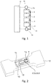
- Fig. 1 shows the main components of the micromechanical strain measuring system (10) and their arrangement comprising at least two connecting elements (1a, 1b), with one connecting element (1b) fixed to the frame and connected to the substrate of the micromechanical strain measuring system (13) and at least one further connecting element opposite the substrate of the micromechanical Strain measuring system (13) is flexibly mounted and the geometric distance between all connecting elements is known.
- the connecting elements create a mechanical coupling between the micromechanical strain measuring system (10) and the object to be measured (12).
- the micromechanical strain measuring system includes a mechanical amplifier (2) and an electro-mechanical signal converter (3).
- the expansion sensor also includes, in an expanded version, a clutch (6) and a mechanical maximum value memory (4).
- the order and arrangement of the main components can vary.
- the application and handling of the micromechanical strain measuring system is similar to that of a strain gauge.
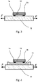
- the strain sensor (10) is, as in Fig. 2 shown, in the form of a chip to the surface to be examined of a measurement object (12) adhesively bonded / joined in a form-fitting manner.
- the chip is connected to the workpiece via at least two defined points, the connecting elements (1a, 1b).
- the distance between the connecting elements (1a, 1b) is precisely known and is determined by a geometry on the chip.
- At least one of the connecting elements is softly supported on the chip via spring elements (1a) and can be moved translationally or rotationally with little effort.
- the other connection point (1b) is rigidly connected to the substrate / frame of the chip.
- both connecting elements are mechanically connected to the measurement object (12), as in FIG Fig. 3 shown.
- the chip is not mounted directly on the measurement object (12), but rather as in FIG Fig. 4 shown indirectly via a flexible housing (11).
- a flexible printed circuit card can be used for this, on which the micromechanical strain measuring system (10) is mounted via the two connecting elements (1a, 1b).
- the flexible housing (11) is in turn attached to the measurement object (12).
- the flexible housing initially absorbs the expansion of the measurement object (12) and then transmits this to the actual expansion sensor.
- the housing is an advantageous extension to protect the mechanical strain sensor from dirt or moisture or to optimize the assembly of the "strain sensor and housing", for example by using large adhesive surfaces.
- glass, silicon, ceramic or glass ceramic substrates come into consideration as the material for the flexible housing.
- a thin, flexible substrate with a silicon-matched substrate is used for the flexible housing Thermal expansion coefficient or used with a particularly low or negligibly small thermal expansion coefficient.
- the use of a material with a coefficient of thermal expansion adapted to the measurement object (12) is also conceivable.
- the micromechanical strain measuring system (10) can preferably be hermetically sealed and connected to the flexible housing (11) via anodic, eutectic or fusion bonding. Through the choice of material for the flexible housing (11), the difference in the thermal linear expansion between the measuring object and the micromechanical strain measuring system is taken into account during the measurement and can thus be compensated in order to prevent thermally induced mechanical tension in the measuring system.
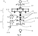
- Fig. 5 shows a possible embodiment of the strain sensor (10).
- the connecting elements (1a, 1b) are displaced relative to one another on the chip on the micromechanical expansion measuring system.
- connection points / connecting elements experience are very small, as can be seen in the above example, so that the displacement amplitude (here 10 ⁇ m) has to be amplified by a mechanical amplifier (2) in the form of a lever mechanism.
- a micromechanical amplifier (2) is used for this, which converts the slight shift at the amplifier input (2.1) into a larger shift at the amplifier output (2.2).
- the increased displacement is transmitted to a translatory runner (8) at the output.
- the mechanical amplifier (2) is also designed to implement a predefined transfer function of the gain as a function of the displacement. In addition to a constant path gain, there are also non-linear gain curves depending on the input shift. Thus, with the aid of the amplifier (2), it is possible to adapt the sensitivity curve of the strain measurement for different value ranges.
- An electromechanical signal converter (3) is implemented at the output of the mechanical amplifier (2) for the electrical detection of the displacement and thus the expansion of the test object.
- a geometric coding in the form of contact electrodes (3.1.1) can be impressed on the rotor (8) which is mounted on the amplifier output (2.2).
- the electrodes (3.1.1) mounted on the rotor and the electrodes (3.1.2) mounted on the frame are initially galvanically separated when the rotor is not deflected.
- an electrical direct or alternating voltage U 0 is introduced and applied to the rotor (8), for example via a conductive guide spring (7).
- the voltage on the contact electrodes (3.1.2) fixed to the frame is tapped and measured.
- the electrical potential at the counter-electrodes (3.1.2) is drawn to a known and fixed potential via high-resistance pull-down or pull-up resistors (3.1.5) as long as the frame-mounted counter-electrodes (3.2.1) are the movable finger electrodes on the rotor Do not touch (3.1.1). Since no current flows through the pull-down or pull-up resistors, no voltage drops across the resistors.
- the strain sensor as described so far, is able to carry out strain measurements continuously. So far, no values have been stored mechanically. As previously described, the strain measurement is therefore only active, i.e. only possible using an electrical energy source. Frequently, however, no continuous query of the measured values is necessary. It is often sufficient to provide information as to whether a certain maximum value of the elongation has been reached or exceeded.
- an expansion of the system makes it possible to store the maximum values of the elongation.
- a mechanical maximum value memory (4) is implemented on the rotor in addition to the electromechanical converter.
- the maximum value memory can optionally be designed in such a way that it can be reset to its original state via a reset mechanism (5), the stored maximum value being deleted.
- a coupling (6) can therefore be used between one of the connecting elements (1a, 1b) and the mechanical maximum value memory (4) implemented.
- the clutch (6) is designed to selectively transmit a force introduced by the connecting element to the mechanical maximum value memory (4) only in a direction intended for this purpose.
- the strain sensor as described so far, is able to detect strains of a measurement object without distinguishing between mechanically induced uniaxial strain and thermally induced isotropic strain as a result of thermal expansion.
- the device according to the invention is therefore extended by a compensation mechanism (14), which is designed to compensate for the isotropic thermal expansion of a measurement object and to decouple it from a uniaxial strain signal of the measurement object, so that purely mechanically induced, temperature-independent strain measurements are made possible.
- Figure 7A shows a possible structure of the compensation mechanism (14).
- the compensation mechanism (14) is constructed symmetrically and is installed between the amplifier input (2.1) and the flexibly mounted connecting element (1a). Any positioning within the measuring device is also possible.
- the compensation mechanism (14) comprises at least one additional flexibly mounted connecting element (1c, 1d) and at least one deflection mechanism (14.2), which is designed to transform a displacement of the connecting element (1c, 1d) in the lateral direction into a displacement in the longitudinal direction.
- the mechanism comprises a force transformer (14.1), for example in the form of a spring, which is designed to convert a displacement into a force F.
- Figure 7A also shows the function of the compensation mechanism (14): If the measured object (12) to be monitored expands isotropically, i.e. evenly in all directions, e.g.
- the distance between the connecting elements (1a, 1b) changes in the longitudinal direction ( y-direction) and on the other hand the distance between the connecting elements (1c, 1d) in the lateral direction (x-direction).
- the lateral displacement of the additional connecting elements (1c, 1d) is turned into a longitudinal displacement via the deflection mechanism (14.2) and into a force F 1 in the longitudinal direction via the power transformer (14.1) (y-direction) converted.
- the force F 1 is then applied directly or indirectly to the input of the mechanical amplifier (2.1).
- the flexibly mounted connecting element (1a) is also connected to the input of the amplifier (2.1) via a power transformer (14.1).
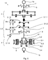
- Fig. 8 shows a simplified embodiment in which the compensation mechanism (14) is mounted on the measuring device according to the invention without a maximum value memory.
- the compensation mechanism (14) can also be operated in combination with a maximum value memory. The order and interconnection of the components can vary.
- the device according to the invention can also be used to measure further physical quantities by means of a simple modification instead of a strain measurement.
- the flexibly mounted connecting element (1a) is not connected directly to the test object (12), but to a mechanical input transducer (16). It is conceivable, for example, that only the frame-mounted connection element (1b) is mounted on the test object to measure and store the amplitude of an acceleration effect on a test object (12), while the flexible mounted connection element (1a) is connected to a seismic test mass (16.1).
- the deflection of the test mass (16.1) also causes a relative displacement between the frame-mounted and flexible connecting elements (1a, 1b) which is recorded, amplified, stored and directly digitized in accordance with the sensor and storage concept of the device according to the invention.
- the connecting elements (1) serve to connect the strain sensor (10) and the test object (12) to be examined or the housing (11) located between the test object (12) and the strain sensor (10).
- the connecting elements (1a, 1b) have fixed positions and distances on the strain sensor (10). The greater the distance between the connecting elements, the more sensitive the strain measurement, but the less precise the spatial resolution of the strain measurement.
- At least one connecting element is firmly connected to the substrate of the microsystem (1b), while at least one further element is mounted in a translational manner relative to the substrate / frame (1a), e.g. via solid joints or guide springs.
- the expansion of the test object is transmitted to the expansion sensor (10) in the form of a displacement via the connecting elements.
- the surface of the connecting elements differs from the remaining surfaces of the micromechanical measuring system in that they have a surface topology and surface morphology optimized for joining.
- an additional adhesion promoter is deposited on the connection surfaces, which allows the connection elements to be locally glued or soldered to a workpiece or test specimen, while the other surfaces of the chip are not wetted by the solder or adhesive. It is also possible to deposit solder, adhesive or reactive layers of, for example, Ni / Al on the connection surfaces in order to implement a local welding process.
- FIG. 9 A technical implementation of the mechanical amplifier is in Fig. 9 shown.
- the mechanism is symmetrical and comprises at least two parallel levers (2.3.1) on each side.
- Each lever (2.3.1) is rotatably mounted with respect to the frame / substrate (13).
- the levers (2.3.1) are coupled to one another in pairs via a lever connector (2.3.2) on one side. In this way, the lever gain of the first lever is increased again by the second, third, etc., so that the overall gain of the mechanical amplifier A total results approximately from the multiplication of the individual lever gain factors A j:
- the multiplicative link makes it possible to achieve relatively high amplification factors of preferably 1 ... 1000 and to implement the amplifier in a very small space.
- FIG. 10 Figure 3 shows another embodiment of the mechanical amplifier.
- m levers are connected to one another in series via lever connectors.
- A. total y out
- the joints of the two-dimensional reinforcement mechanism implemented using microsystem technology can be implemented in the form of solid body joints in order to avoid abrasion on the joint axes.
- there is no need for sliding joints at the entrance and exit as the restoring forces of the solid-state joints and the symmetrical structure of the mechanism compensate for any transverse forces at the entrance or exit.
- a translational shift on the input side is thus converted into a likewise pure translational shift at the output. Additional sliding joints are therefore optional when using solid body joints.
- the mechanical amplifier (2) can also be used to set the input and output stiffness of the amplifier (2).
- the rigidity of the booster is determined by the rigidity c i of the flexure joints and the reinforcement of the individual levers. The stiffer the system input, the greater the effort that has to be applied to move the input element of the amplifier.
- Fig. 11 shows an expanded version of the amplifier (2) with an implemented transfer function, in which it is possible, in addition to a constant gain factor, to apply a shift-dependent gain factor to the input-side shift.
- the gain A total ( y in ) represents a function of the input shift y in .
- At least one of the joints that connect the lever mechanism to the substrate is replaced by at least one cam (2.3.4) on the lever mechanism, the predefined transfer function being implemented on the cam (2.3.4).
- the associated lever (2.3.1) is deflected, it is not rotated about a point fixed to the substrate defined by a fixed joint, but moves along the cam (2.3.4). Since the lever slides along the cam, the pivot point also moves as a function of the displacement, whereby the associated distance a or b or c or d and thus the gain changes as a function of the displacement, as in FIG Fig. 12 will be shown.
- the task of the electromechanical converter (3) is to convert the displacement at the output of the amplifier (2.2) into an electrical signal.
- electromechanical condition detection there are various options for electromechanical condition detection.
- the shift can be controlled using a capacitive converter (3.3), as in Fig. 13 shown, capture.
- a capacitive converter 3.3
- isolated, freely movable electrodes can be implemented on the microsystem, which form a parallel plate capacitor. The electrodes can be moved relative to one another and thus allow the capacitance of the capacitor to be varied. The displacement of the rotor (8) can thus be determined by evaluating the capacitance.
- the disadvantage of this solution is that the measuring system can only be used in combination with a capacitance measuring circuit, which means that parasitic effects such as thermal noise also influence the measured value.
- a contact-based converter is therefore preferably used.
- Fig. 14 shows the general functional principle of the converter.
- the transducer comprises n W frame-fixed and flexibly mounted counter-electrodes (3.1.2) as well as finger electrode groups (3.1.3) belonging to them in pairs.
- the finger electrode groups are mounted on the runner (8) of the strain sensor and can be moved translationally along the runner direction with the runner.
- the counter-electrodes are fixed to the frame along the finger electrode groups.
- a finger electrode group (3.1.3) comprises one or more finger electrodes (3.1.1), which are characterized in that they establish electrical contact with the counter-electrodes fixed to the frame or there is a change in impedance between the counter-electrodes and finger electrodes in the event of a defined translational deflection of the rotor as soon as both electrodes are facing each other.
- the position of the rotor is clearly geometrically coded through the arrangement of the electrodes.
- an electrical voltage U 0 is applied to the rotor.
- the voltage on the frame-mounted counter-electrodes (3.1.2) is measured or tapped.
- a first defined electrical potential for example 0 V, is applied to the counter electrodes. This defined first electrical potential is ensured, for example, via pull-down or pull-up resistors on the counter-electrodes that are fixed to the frame.
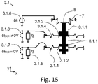
- FIG. 15 shows an example of how the state of displacement of the rotor is tapped at the pull-down resistors.
- the counter and finger electrodes of bit 1 are in contact, so that a voltage not equal to 0 V drops across the associated pull-down resistor.
- the finger and counter electrodes of bit 0 are not contacted, consequently no voltage drops at the associated pull-down resistor.
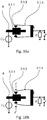
- the distance between finger electrodes and counter-electrodes can on the one hand be designed to overlap, so that when the finger electrodes are displaced, they slide along the counter-electrodes. Such a configuration is used, for example, in Figure 16a shown.
- the counter electrodes and finger electrodes can also be positioned at a short distance from one another, as in FIG Figure 16b shown. When an electrical voltage is applied between the two electrodes, an electrostatic force is created which presses the flexibly mounted counter-electrodes against the finger electrodes so that voltage is transferred.
- the advantage of the embodiment in which the electrodes are at a short distance from one another and only touch when a voltage is applied is that there is little friction between the electrodes and the electrodes only contact each other mechanically during the actual electrical readout.
- the mechanical contact time can also be kept very short by applying an alternating voltage.
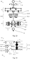
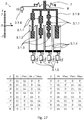
- the finger electrode groups (3.1.3) can be arranged either in series on the rotor (8) or in a comb structure, such as Fig. 17 shows.
- the finger electrode groups (3.1.3) and the frame-mounted counter-electrodes (3.1.2) are arranged parallel to the rotor axis (y-direction).
- the binary coding via the finger electrodes is in Fig. 17 realized by way of example in the form of Gray code, other forms of binary coding such as dual code or BCD code are also conceivable.
- an additional pair of finger and counter electrodes is added as an additional sign branch (3.1.9) in a further preferred embodiment.
- the finger electrodes that contribute to the binary coding are then extended by a second, mirror-symmetrical arrangement of the finger electrodes on the rotor, as in FIG Fig. 17 shown.
- Fig. 17 Using a table, shows the voltages that ideally drop across the pull-down resistors depending on the rotor position y.
- the voltages tapped in parallel form a discrete electrical parallel binary signal with Gray coding.
- the voltage U S indicates the sign of the expansion or the displacement of the rotor in the y-direction.
- a capacitive or piezoresistive converter for example, can also be used as the converter.
- thermometer code e.g. 0001111
- a decimal number instead of a binary coded signal.
- the coding unit of the electro-mechanical converter is adapted to the corresponding number or coding system.
- Fig. 18 shows an embodiment for encoding a decimal number while Fig. 19 represents an embodiment for the coding of so-called thermometer code.
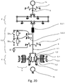
- Fig. 20 shows the implementation of a coding unit for the transmission of thermometer code in the overall system.
- Fig. 21 shows a further embodiment of a bi-directional strain sensor in which the electro-mechanical transducer has a comb structure, contains a sign branch (3.1.9) and Gray code was selected as the binary coding of the finger electrode groups (3.1.3).
- Fig. 22 shows a further preferred embodiment of the signal converter (3) in combination with a mechanical maximum value memory (4).
- a predefined discrete transfer function is implemented on the micromechanical analog-digital converter (3.1).
- the distances between the ratchet teeth on the mechanical maximum value memory can also be adapted to the distances between the finger electrodes (3.1.1).
- the implementation of a predefined transfer function is suitable e.g. B. for linearization and / or for adapting the measurement sensitivity over a defined displacement and thus measurement range.
- Fig. 22 also shows that the sequence of micromechanical amplifier and electromechanical signal converter (3) can vary in structure.
- the exemplary embodiment also makes it clear that the mechanical maximum value memory (4) can also be designed for bi-directional maximum value storage.
- a particular advantage of the electro-mechanical converter in the form of the micromechanical analog-digital converter (3.1) is the discretization and digitization of a shift in the mechanical domain. No further active electrical components are required for the binary coding of the expansion or displacement signal at the input of the converter. Due to the possibility of setting a small distance between the finger and counter electrodes, the actual strain measurement is only influenced by, for example, friction while the transducer (3.1) is reading. In addition, only a number of n finger electrode groups (3.1.3) with possibly an additional sign branch (3.1.9) are required for a signal resolution of n bits. This enables a large number of discretization steps with minimal space requirements. In addition, any binary codes and any transfer functions can be set via the arrangement and size of the finger electrodes to implement. Thus, in addition to passive digitization, an initial passive data preparation is already possible by adapting the characteristic curve via the converter.
- Fig. 23 shows a preferred embodiment of the mechanical maximum value memory (4).
- the mechanical maximum value memory (4) is based on a locking mechanism consisting of locking blades (4.2) and at least one locking element (4.1) with locking teeth (4.3) located thereon.
- the locking elements are attached to the runner (8), while the locking blades (4.2) are fixed to the frame and connected to the substrate / frame of the strain sensor.
- a reverse arrangement is also possible. If the runner (8) is moved, the locking teeth (4.3) on the runner slide over the pawl, which is fixed to the frame, but is flexibly and spring-loaded.
- the ratchet teeth are designed in such a way that the ratchets slide against each other in one direction (eg y-direction), but form a positive fit when moving in the opposite direction, so that the backward movement is blocked.
- the positive connection does not allow the rotor (8) to return to its initial position, so that the maximum value of the rotor deflection that has been reached is saved.
- the size of the ratchet teeth and their spacing are largely determined by the resolution of the lithography during production.
- the more precise the production the smaller the distance a RZ can be implemented and the smaller the step size y s between the individual discretization steps.
- the friction angle ⁇ on the ratchet teeth is limited by the coefficient of static friction between the surfaces sliding against one another.
- the minimum step size y s of the discretized position detection is determined by the distance between the individual ratchet teeth a RZ. The following applies to the minimum step size y s from detent position to detent position: y S. ⁇ a RZ
- the mechanical memory can be supplemented by pairs of locking mechanisms consisting of locking elements and Pawls are added as in Fig. 24 will be shown.
- the distance a RZ of the individual locking teeth (4.3) can be identical for each additional locking element (4.1), but can also vary.
- the size and the distance between the ratchet teeth are largely limited by the resolution of the lithography.
- a smaller step size y s can, however, be achieved in that a defined offset of the locking tooth position is implemented with each additional pairing.
- the initial distance b RZ, i between the respective first locking tooth of an i -th locking element and the associated i -th locking blade can vary in relation to a further pairing.
- a offset is a production-related offset that should be identical for all n pairs.
- y S. a RS n
- the size of the ratchet teeth and their spacing are largely determined by the resolution of the lithography. Furthermore, the friction angle on the ratchet teeth is limited by the coefficient of static friction between the surfaces sliding against one another. Since the distance between the ratchet teeth limits the step size a RZ of the discrete steps and thus the resolution of the memory, further ratchet mechanisms can be added to the system, but these are offset by a RZ / n . In this way, the ratchet teeth can also assume intermediate positions regardless of the lithographic resolution.
- Fig. 24 shows a locking mechanism in which the minimum lithography-related step size a RZ is divided into three by a second locking mechanism offset by a RZ / 3 and a second by 2 a RZ / 3.
- the latching mechanism shown can occupy as six fixed positions spaced from a RZ / 3, where a displacement of the rotor to a RZ is necessary for the first position from the initial position.
- the locking blades (4.2) must be released from the ratchet teeth (4.3).
- Various conventional microsystem technology actuators can be used for this purpose.
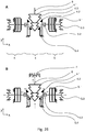
- a preferred reset mechanism (5) based on electrostatic actuators (5.1) is shown for this purpose.
- possible embodiments also include thermal actuators that can apply a particularly high force and thereby require little space on the chip.
- Figure 26B shows how the reset mechanism releases the contact between the locking blades (4.2) and the ratchet teeth (4.3).
- the reset mechanism is connected to the locking mechanism or the locking blades via a reset clutch (5.2).
- the task of the reset clutch is to unidirectionally decouple the movements of the pawl blades that occur during the storage process from the reset mechanism, but at the same time to pass on the displacement and force exerted by the actuator to the locking mechanism, in particular to the pawl blades, in order to release the pawl blades from the locking teeth.
- carriers (5.4) ensure the distribution of the force and displacement transmission from the actuator to all locking blades to be released (4.2).
- the mechanical maximum value memory can also be designed in connection with a clutch (6). If the maximum value reached is saved by the locking mechanism, the rotor (8) is permanently deflected. If, however, the component to be monitored then relaxes or is stressed in the opposite direction, a high force acts on the rotor (8) and thus also on the ratchet teeth, which could destroy the mechanism. For this reason, the maximum value memory (4) can be mechanically decoupled from the connecting element (1a, 1b) via a coupling (6).
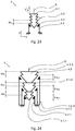
- the coupling can consist of two opposing, mechanically separated plungers, as in FIG Fig. 27 shown.
- One of the plungers (6.1) is attached directly to the connecting element, while the associated second plunger (6.2) is placed at the input of the mechanical amplifier.
- Displacements of the connecting element in the negative y-direction are transmitted to the second tappet via the first tappet.
- the connecting element is deflected in the other direction, this has no effect on the second tappet and thus on the rest of the mechanism.
- the micromechanical measuring system can alternatively or in addition to the strain measurement also be used for energy self-sufficient measurement of further physical quantities.
- the flexibly mounted connecting element (1a) is preferably not connected directly to a test object (12) to be stretched, but alternatively to a mechanical input transducer (16), which is designed to convert a physical variable to be measured into a displacement or expansion variable in turn causes a relative displacement between the frame-fixed (1b) and flexible connecting elements (1a).
- Fig. 28 shows a possible Arrangement of the individual components on the micromechanical measuring system. To restrict functions, it is possible to swap or remove individual components. This also applies to the pure strain measurement. Fig.
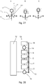
- FIG. 29 shows an example of a preferred embodiment of the micromechanical measuring system in which the flexibly mounted connecting element (1a) is connected to a seismic mass (16.1) which serves as a mechanical input transducer (16) to measure an acceleration.
- a seismic mass (16.1) which serves as a mechanical input transducer (16) to measure an acceleration.
- other embodiments of the mechanical input transducer (16) for alternative physical measured variables such as temperature, current, voltage, humidity, electrical or magnetic field strengths are also conceivable.
- the use of magnetic, dielectric materials or electret on the flexibly mounted connecting element (1a) as a mechanical input transducer (16) is conceivable in particular for the detection of field variables.
- Electrostatic or electrothermal actuators from microsystem technology known from the prior art can be used to detect current and voltage.
- Bi-Morphe or actuators made of shape memory alloy can be implemented between the flexibly mounted connecting element and the frame to record temperatures.
- strain measuring system can be implemented with various technologies, in particular with processes of microsystem technology.
- SOI substrate silicon insulator
- SOI substrate siliconon insulator
- These substrates comprise three layers: a so-called “device layer”, consisting of or containing monocrystalline silicon (15.1), a “buried oxide layer” (BOX layer) made of SiO 2 (15.2) and a further layer consisting of or containing monocrystalline silicon , the "handelayer” (15.3).
- the device layer (15.1) carries the freely movable, two-dimensional mechanical structures such as the mechanical amplifier (2) or the maximum value memory (4), while the handle layer (15.3) can be understood as a mechanical frame that is placed over the SiO 2 layer of the BOX -Layers (15.2) is connected to the mechanical structures of the device layer at firmly defined points.
- the BOX layer (15.2) forms a sacrificial layer that is partially removed below the freely movable structures.
- both the device layer (15.1) and the handle layer (15.3) are structured. All the mechanical and electromechanical components are implemented in the device layer (15.1), while the connecting elements (1a, 1b) are provided on the handle layer (15.3) and connect the sensor to a measurement object (12) or a flexible housing (11). Alternatively, the connecting elements can also be attached to the device layer. Handle and device layers are connected via the BOX layer (15.2) so that the mechanical displacement at the connection elements can be transferred to the device layer.
- Figure 30A the layer structure of the system including the electrodes (15.4) and the connecting material for the form-fitting connection (15.5) is shown.
- Figure 30B shows an alternative layer structure in which the handle layer (15.3) is not structured, but the device layer (15.1) is connected directly to the flexible housing (11) via the connecting material (15.5).
- Figure 30C shows another possible arrangement in which the device layer is connected to the flexible housing directly via the connecting elements (1a, 1b, possibly 1c, 1d).
- the flexible housing (11) has a cavity in the area of the freely movable components.
- a material connection between the connecting elements (1a, 1b) and the flexible housing is also possible without connecting material, for example via anodic, eutectic or fusion bonding, provided that a suitable material such as glass or silicon is used
- Substrate for the flexible housing (11) is used.
- a solder, an adhesive and / or a layer stack of reactive metal layers e.g.
- the use of structured reactive metal layers allows the measuring device to be firmly joined to the flexible housing on a measurement object by local and surface welding / soldering through a highly exothermic alloying of the stacked metal layers after the activation energy required for the reaction has been exceeded, for example by a laser pulse or an ignition spark.
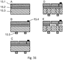
- the starting point for the production process is an SOI substrate or a substrate consisting of three levels, the middle level (15.2) representing a sacrificial layer, the device layer level (15.1) the functional layer and the handlayer level (15.3) the task of the mechanical frame (13) takes over ( Figure 31A ).
- a metal layer e.g. made of aluminum, is deposited on the device layer (15.1) of the wafer for electrical contacting ( Figure 31B ).
- a photolithography is then carried out in which the desired geometry is mapped onto the device layer.
- the previously deposited metal layer is partially removed by a further etching step and the layer is thus structured.
- the remaining photoresist on the hand layer is then removed.
- structuring of the electrodes using a lift-off method is also possible.
- connection elements (1a, 1b) are additionally modified, e.g. by depositing a composite material (15.5) ( Figure 31B ).
- a composite material 15.5 ( Figure 31B ).
- the geometry of the mechanical components of the sensor is transferred to the device layer (15.1 ) projected.
- the device layer (15.1) is then deeply etched through reactive ion deep etching ("DRIE" process) up to the next layer ( Figure 31C ).
- DRIE reactive ion deep etching
- the structures on the hand layer are etched through to the oxide layer ( Figure 31D ).
- additional metal layers can also be deposited on the deeply etched flanks of the device layer. These metal layers can still be structured by ion beam etching.
- the silicon structures are not yet freely movable up to this point.
- a hydrofluoric acid vapor or HF gas (HF vapor) process is now carried out, in which the SiO 2 layer between the handle and device layer is partially removed ( Figure 31E ).
- Hydrofluoric acid only undercuts those structures on the device layer that are sufficiently narrow and offer a large surface area to attack. Wide structures are undercut more slowly and are therefore still firmly connected to the handle layer via the SiO2.
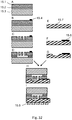
- Fig. 32 shows an alternative production sequence for the production of the micromechanical measuring system and the mounting of the measuring system on a flexible housing (11).
- Figure 32A first shows the provision of an SOI substrate (15.1, 15.2, 15.3).
- Figure 32B the deposition and structuring of a metal layer (15.4) is shown which is required for the electrical connections.
- Figure 32C After structuring the device layer (15.1) via photolithography and anisotropic etching ( Figure 32C ) the movable structures of the micromechanical measuring system are released using hydrofluoric acid ( 32D).
- Figure 32E also shows the provision of a substrate (15.7) for the flexible housing. This substrate is preferably glass, glass ceramic, ceramic or likewise silicon.
- a metal layer for leading out electrodes (15.6) is also deposited and structured on the substrate (15.7) ( Fig.
- the substrate (15.7) of the flexible housing is structured via lithography and etching in such a way that cavities are generated on the substrate.
- the SOI substrate and the flexible package substrate are in Figure 32H joined at the points of the connecting elements (1a, 1b, possibly 1c, 1d) via a bonding process. Other connections for hermetic sealing are also possible.
- connecting materials (15.5) such as reactive metal layers, solder or adhesive are deposited flat or structured on the surface of the flexible housing.
- VDI / VDE 2635 sheet 1 Experimental structural analysis of strain gauges with a metallic measuring grid, parameters and test conditions; July 2015
- VDI / VDE 2635 sheet 2 Experimental structural analysis Recommendation for performing strain measurements at high temperatures
Abstract
Die vorliegende Erfindung betrifft eine Vorrichtung und ein Verfahren zur ortsaufgelösten Dehnungsmessung an bestimmten Stellen eines mechanisch beanspruchten Bauelements. Die vorliegende Erfindung betrifft eine Vorrichtung zur mechanischen Dehnungsmessung über zwei Verbindungselemente, deren Verschiebung über einen mechanischen Verstärker verstärkt und über einen elektromechanischen Wandler in eine elektrische Größe gewandelt wird. Die Erfindung betrifft außerdem eine mechanische Maximalwertspeicherung sowie die damit verbundene Möglichkeit einer energieautarken Dehnungsmessung und -überwachung. Die Erfindung betrifft weiterhin ein Verfahren zur Bestimmung der Dehnung eines Messobjekts mit Hilfe des erfindungsgemäßen mikromechanischen Messsystems (Fig. 1).The present invention relates to a device and a method for spatially resolved strain measurement at certain points of a mechanically stressed component. The present invention relates to a device for mechanical strain measurement via two connecting elements, the displacement of which is amplified via a mechanical amplifier and converted into an electrical variable via an electromechanical converter. The invention also relates to a mechanical maximum value storage and the associated possibility of energy self-sufficient strain measurement and monitoring. The invention further relates to a method for determining the expansion of a measurement object with the aid of the micromechanical measurement system according to the invention (FIG. 1).
Description
Die vorliegende Erfindung betrifft eine Vorrichtung und ein Verfahren zur ortsaufgelösten Dehnungsmessung an bestimmten Stellen eines mechanisch beanspruchten Bauelements. Die Erfindung betrifft insbesondere eine Vorrichtung zur mechanischen Dehnungsmessung über zwei Verbindungselemente, deren Verschiebung über einen mechanischen Verstärker verstärkt und über einen elektromechanischen Wandler in eine elektrische Größe gewandelt wird. Die Erfindung betrifft außerdem eine mechanische Maximalwertspeicherung sowie die damit verbundene Möglichkeit einer energieautarken Dehnungsüberwachung.The present invention relates to a device and a method for spatially resolved strain measurement at certain points of a mechanically stressed component. The invention relates in particular to a device for mechanical strain measurement via two connecting elements, the displacement of which is amplified via a mechanical amplifier and converted into an electrical variable via an electromechanical converter. The invention also relates to a mechanical storage of maximum values and the associated possibility of energy self-sufficient expansion monitoring.
Zur Überwachung stark beanspruchter Bauelemente werden häufig Dehnungsmessstreifen (DMS) eingesetzt. Über DMS lassen sich Dehnungen und Spannungen an bestimmten Stellen eines mechanisch beanspruchten Bauelements lokal aufgelöst bestimmen. DMS sind dehnungssensitive elektrische Widerstände, deren Widerstandswert mit zunehmender Dehnung steigt bzw. bei zunehmender Stauchung sinkt. Über die Messung des Widerstandes lässt sich so die aktuell vorliegende Dehnung äußerst genau bestimmen.Strain gauges are often used to monitor heavily used components. With strain gauges, strains and stresses can be determined locally resolved at certain points of a mechanically stressed component. DMS are strain-sensitive electrical resistors whose resistance value increases with increasing elongation or decreases with increasing compression. The current strain can be determined extremely precisely by measuring the resistance.
Im Stand der Technik werden Dehnungsmessungen an makroskopischen Bauelementen mit Hilfe von resistiven Dehnungsmessstreifen (DMS) und piezoresistiven Dehnungsmesssystemen durchgeführt.In the prior art, strain measurements are carried out on macroscopic components with the aid of resistive strain gauges (DMS) and piezoresistive strain measurement systems.
Bei DMS handelt es sich um meist selbstklebende Streifen mit Halbleiter- oder Metallleiterbahnen, die einen elektrischen Widerstand bilden. Wird der DMS gedehnt oder gestaucht, so verändert sich aufgrund der geometrischen Verformung und der Änderung des spezifischen Widerstandes der Gesamtwiderstand des DMS. Es ergibt sich eine Widerstandsänderung ΔR/R, die sowohl von der Dehnung ε als auch vom materialspezifischen k-Faktor abhängig ist: ![]()
![]()
Für Metalle liegt der k-Faktor in der Größenordnung 1,5 bis 3. Halbleiter erreichen Werte zwischen 20 bis 100 (Schomburg, 2011; Gerlach und Dötzel, 2006). Die Sensitivität der Widerstandsänderung gegenüber der Dehnung ist folglich auch bei sehr hohen Dehnungen von 1% sehr klein.For metals, the k factor is in the order of 1.5 to 3. Semiconductors reach values between 20 and 100 (Schomburg, 2011; Gerlach and Dötzel, 2006). The sensitivity of the change in resistance to elongation is consequently very low even at very high elongations of 1%.
Da die Widerstandsänderung viel sensitiver auf Temperaturänderungen als auf Dehnungsänderungen reagiert, werden DMS stets in einer "Wheatstone-Messbrücke" verschaltet, um den Temperatureinfluss zu kompensieren. Wird als Messbrücke eine Viertel- oder Halbbrücke eingesetzt, so wird die Dehnungssensitivität jedoch zusätzlich auf ein Viertel bzw. auf die Hälfte reduziert. Zum Auswerten der Widerstandsänderungen bzw. der Brückenspannung ist zudem eine aufwendige analoge Schaltung notwendig. Meist werden Instrumentenverstärker genutzt, um das schwache analoge elektrische Messsignal zu verstärken (Tietze et al. 2012). Außerdem muss fast immer eine Offset-Korrektur der Brückenspannung durchgeführt werden, da die Widerstandswerte der Referenzwiderstände in der Messbrücke fertigungsbedingt nicht identisch sind und sich so in der Regel eine Offset-Spannung an der Messbrücke einstellt.Since the change in resistance reacts much more sensitively to changes in temperature than to changes in strain, strain gauges are always connected in a "Wheatstone measuring bridge" in order to compensate for the influence of temperature. If a quarter or half bridge is used as the measuring bridge, the strain sensitivity is additionally reduced to a quarter or half. A complex analog circuit is also required to evaluate the changes in resistance or the bridge voltage. Instrument amplifiers are mostly used to amplify the weak analog electrical measurement signal (Tietze et al. 2012). In addition, an offset correction of the bridge voltage must almost always be carried out, since the resistance values of the reference resistors in the measuring bridge are not identical due to manufacturing reasons and an offset voltage is usually set on the measuring bridge.
Nähere Einzelheiten zu Dehnungsmessstreifen finden sich im VDI/VDE 2635 Blatt 1 und Blatt 2.More details on strain gauges can be found in VDI / VDE 2635
Eine weitere Möglichkeit der Dehnungsmessung besteht in der Anbringung von Faser-Bragg-Gittern am zu dehnenden Bauelement. Hierzu wird ein Lichtstrahl in einen Lichtwellenleiter mit Faser-Bragg-Gitter eingeleitet und am anderen Ende des Leiters spektral analysiert. Über die spektrale Verschiebung der reflektierten Wellenlänge lässt sich Aufschluss über die Längenänderung des Leiters gewinnen (Chen et al.;
Das Funktionsprinzip von Faser-Bragg-Gittern (engl. "fiber Bragg grating", FBG) beruht auf dem Prinzip der Fresnel Reflektion. Hierzu werden in einem Lichtwellenleiter Bereiche mit unterschiedlichen Brechungsindizes erzeugt, die sich vom Brechungsindex der eigentlichen Faser unterscheiden. Diese Bereiche werden i.d.R. in einem periodischen Abstand mit der optischen Länge d = λ/2 angeordnet, wobei sich die einzelnen Bereiche aus je zwei λ/4- breiten Einzelschichten mit unterschiedlichem Brechungsindex zusammensetzen. Licht, das durch den Lichtwellenleiter geführt wird, wird abhängig von der Wellenlänge an den optischen Grenzflächen der modifizierten Bereiche reflektiert. Die Reflektion bestimmter Wellenlängen ergibt sich aus der Phasenverschiebung der reflektierten Lichtwelle um 180° bzw. 0° beim Auftreffen auf eine optische Grenzfläche. Durch die Phasenverschiebung und den λ/4 breiten optischen Schichten kommt es bei der reflektieren Welle mit der Wellenlänge λ zu konstruktiver Interferenz. Die Phasenverschiebung hängt dabei davon ab, ob das Licht zunächst aus einem Bereich mit hohem Brechungsindex kommt und auf einen Bereich mit niedrigem Brechungsindex (0°) stößt oder ob es umgekehrt von einem Bereich mit niedrigem Brechungsindex auf einen Bereich mit hohem Brechungsindex (180°) stößt.The functional principle of fiber Bragg gratings (English "fiber Bragg grating", FBG) is based on the principle of Fresnel reflection. For this purpose, areas with different refractive indices are generated in an optical waveguide, which differ from the refractive index of the actual fiber. These areas are usually arranged at a periodic distance with the optical length d = λ / 2, whereby the individual areas are made up of two λ / 4-wide individual layers with different refractive indices. Depending on the wavelength, light that is guided through the optical waveguide is reflected at the optical interfaces of the modified areas. The reflection of certain wavelengths results from the phase shift of the reflected light wave by 180 ° or 0 ° when it hits an optical interface. Due to the phase shift and the λ / 4 wide optical layers, constructive interference occurs in the reflected wave with the wavelength λ. The phase shift depends on whether the light initially comes from a region with a high refractive index and hits a region with a low refractive index (0 °) or, conversely, from a region with a low refractive index to a region with a high refractive index (180 °). bumps.
Durch eine Dehnung der Faser werden auch die einzelnen Bereiche der Bragg-Schichten gedehnt, wobei sich die optische Länge ändert. Folglich verändert sich auch die Wellenlänge, für die die Bragg-Bedingung erfüllt wird und die entsprechend reflektiert wird. Über eine Analyse der Verschiebung des Reflexions-/Transmissionsspektrums lässt sich so auf die Dehnung der Faser schließen.By stretching the fiber, the individual areas of the Bragg layers are also stretched, with the optical length changing. As a result, the wavelength for which the Bragg condition is met and which is reflected accordingly also changes. An analysis of the shift in the reflection / transmission spectrum allows conclusions to be drawn about the elongation of the fiber.
Der besondere Vorteil von FBG-Dehnungssensoren gegenüber DMS besteht in der Unempfindlichkeit gegenüber elektromagnetischen Feldern, die beim DMS eine zusätzliche Störspannung induzieren könnten. Der Nachteil dieser Lösung besteht in der teuren und aufwendigen Analyse des Spektrums. Zudem muss eine Lichtquelle zur Verfügung stehen.The particular advantage of FBG strain sensors over strain gauges is their insensitivity to electromagnetic fields that could induce additional interference voltage in the strain gage. The disadvantage of this solution is the expensive and time-consuming analysis of the spectrum. A light source must also be available.
Bei standardisierten Werkstoffprüfversuchen werden zur Bestimmung der Dehnung an Zugproben häufig Extensometer genutzt. Eine Dehnungsmessung erfolgt hier meist optisch und berührungslos und ohne Aufkleben von DMS oder FBG. Zur Bestimmung der Dehnung werden auf der Zugprobe Markierungen vorgesehen, die optisch z.B. über Videoanalyse erfasst werden. Die Verschiebung der Markierungen erlaubt es, Aufschluss über die Dehnung des Prüflings zu erhalten. Alternativ können auch interferometrische Prinzipien zur Dehnungsmessung genutzt werden. Eine Übersicht über die verschiedenen Verfahren bieten Tian et al. (2012) sowie
Weitere Sensoren zur Dehnungsbestimmung werden in
Bei der Sensoreinheit in
Die Nachteile dieser Sensoreinheit bestehen in einem hohen Schaltungsaufwand bei der Digitalisierung der Signale und in der beschränkten Präzision durch Elektrodengröße und Nonius-Struktur. Außerdem ist keine Speicherung des erreichten Maximalwerts und keine energieautarke Überwachung möglich.The disadvantages of this sensor unit are the high circuit complexity involved in digitizing the signals and the limited precision due to the size of the electrode and the vernier structure. In addition, it is not possible to save the maximum value reached and no energy self-sufficient monitoring is possible.
Die
Eine passive Vorrichtung zum Zählen von Dehnungsüberschreitungen wird in der
Die Überwachung kritischer Bauelemente mittels DMS erlaubt ein kontinuierliches Monitoring der auftretenden Beanspruchungen. Häufig sind insbesondere für Wartungszwecke allerdings nur die maximal erreichten Dehnungsspitzen von Interesse, sodass die kontinuierlich erfassten Daten meist gar nicht benötigt und damit verworfen werden. Zudem ist eine Bauteilüberwachung mittels DMS äußerst aufwendig, da die DMS zur Temperaturkompensation in einer Messbrücke verschaltet werden und die Signale an den Messbrücken aufbereitet werden müssen. So ist neben der elektrischen Verstärkung der Brückenspannung und der Offset-Korrektur auch noch die Digitalisierung und häufig auch die Speicherung der Messergebnisse erforderlich. Ferner ist für die Messung eine Spannungsversorgung notwendig, die eine Verkabelung der DMS und der Auswerteelektronik mit sich bringt.The monitoring of critical components by means of strain gauges allows continuous monitoring of the stresses that occur. Often, however, especially for maintenance purposes, only the maximum expansion peaks achieved are of interest, so that the continuously recorded data is usually not required at all and is therefore discarded. In addition, component monitoring using strain gauges is extremely complex, since the strain gauges for temperature compensation are interconnected in a measuring bridge and the signals at the measuring bridges have to be processed. In addition to the electrical amplification of the bridge voltage and the offset correction, digitization and often also the storage of the measurement results is required. Furthermore, a voltage supply is necessary for the measurement, which entails cabling of the strain gauges and the evaluation electronics.
Eine Aufgabe der vorliegenden Erfindung bestand deshalb darin, als Alternative zu klassischen widerstandsbasierten DMS ein neuartiges mikromechanisches System bereitzustellen, das vollkommen energieautark eine kontinuierliche mechanische Bauteilüberwachung zulässt.One object of the present invention was therefore to provide a novel micromechanical system as an alternative to classic resistance-based strain gauges, which allows continuous mechanical component monitoring to be completely self-sufficient in terms of energy.
Eine weitere Aufgabe der vorliegenden Erfindung bestand darin, mit einem solchen mikromechanischen System eine mechanische Maximalwertspeicherung zu gewährleisten und dadurch eine energieautarke Dehnungsüberwachung zu ermöglichen.A further object of the present invention was to ensure a mechanical maximum value storage with such a micromechanical system and thereby enable an energy-self-sufficient strain monitoring.
Ähnlich wie DMS, können die hier vorgestellten Mikrosysteme in Form eines Chips zur lokalen Dehnungsüberwachung auf einer Probe befestigt werden, um so die aktuell vorliegende Dehnung oder auch die maximal auftretende Dehnung zu messen und zu speichern. Eine Widerstandsbrücke mit entsprechender Verstärkerschaltung mit Offsetkorrektur sowie ein elektronischer A/D-Wandler ist bei diesem Prinzip nicht erforderlich. Die Messung der Dehnung erfolgt rein mechanisch, sodass elektrische parasitäre Effekte wie thermisches Rauschen im Gegensatz zum resistiven DMS nur eine geringfügige Rolle spielen.Similar to strain gauges, the microsystems presented here can be attached to a sample in the form of a chip for local strain monitoring in order to measure and store the current strain or the maximum strain that occurs. A resistor bridge with a corresponding amplifier circuit with offset correction and an electronic A / D converter are not required with this principle. The strain is measured purely mechanically, so that electrical parasitic effects such as thermal noise only play a minor role in contrast to resistive strain gauges.
Das erfindungsgemäße mikromechanische System hat den Vorteil gegenüber bestehenden Dehnungsmesssystemen, dass keine kontinuierliche Spannungsversorgung für die Dauerüberwachung mittels Maximalwertspeicher notwendig ist und das System vollkommen energieautark eingesetzt werden kann. Es ist keine aufwendige elektrische Verstärkerschaltung und keine Verschaltung in einer Messbrücke notwendig, somit auch kein Abgleichen von Widerständen. Im System erfolgt eine direkte Diskretisierung und Digitalisierung der Messwerte in der mechanischen Domäne. Da es sich bei der Dehnungserfassung um ein rein mechanisches Prinzip handelt, gibt es keine parasitären elektrischen Effekte (wie z.B. thermisches Rauschen).The micromechanical system according to the invention has the advantage over existing strain measurement systems that no continuous voltage supply is necessary for permanent monitoring by means of maximum value memory and the system can be used completely self-sufficient in terms of energy. No complex electrical amplifier circuit and no interconnection in a measuring bridge are necessary, thus no balancing of resistors. In the system there is a direct discretization and digitization of the measured values in the mechanical domain. Since strain detection is a purely mechanical principle, there are no parasitic electrical effects (such as thermal noise).
Das erfindungsgemäße System ist außerdem günstig in der Herstellung, da diese vorzugsweise auf einer standardisierten SOI-Technologie (mit vielen Chips pro Wafer) beruht. Da im Wesentlichen nur Silicium und Metalle, Gläser oder Keramiken bei der Herstellung verwendet werden, ist das System temperaturstabil und umweltschonend. Für die mechanische Verbindung des Systems mit einem Prüfobjekt bestehen viele verschiedene Möglichkeiten; z.B. durch Löten, Schweißen, Verkleben, Bonden.The system according to the invention is also inexpensive to manufacture, since it is preferably based on standardized SOI technology (with many chips per wafer). Since essentially only silicon and metals, glasses or ceramics are used in production, the system is temperature-stable and environmentally friendly. There are many different possibilities for the mechanical connection of the system to a test object; eg by soldering, welding, gluing, bonding.
Die beschriebenen technischen Aufgaben werden durch die Vorrichtungen bzw. Verfahren gemäß den unabhängigen Ansprüchen der aktuellen Erfindung gelöst. Die abhängigen Ansprüche beschreiben bevorzugte Ausführungsformen. Wertebereiche, die durch numerische Werte begrenzt sind, sollen stets die besagten Grenzwerte beinhalten.The technical tasks described are achieved by the devices and methods according to the independent claims of the current invention. The dependent claims describe preferred embodiments. Value ranges that are limited by numerical values should always contain the said limit values.
-
Fig. 1 : Komponenten des mikromechanischen Dehnungsmesssystems und Anbindung an ein MessobjektFig. 1 : Components of the micromechanical strain measuring system and connection to a measuring object -
Fig. 2 : Anbindung des mikromechanischen Dehnungsmesssystems an einem Messobjekt bzw. an einer ZugprobeFig. 2 : Connection of the micromechanical strain measuring system to a measurement object or a tensile specimen -
Fig. 3 : Darstellung der direkten Verbindung des mikromechanischen Dehnungsmesssystems mit einem MessobjektFig. 3 : Representation of the direct connection of the micromechanical strain measuring system with a measuring object -
Fig. 4 : Darstellung der indirekten Verbindung des Dehnungssensors mit einem Messobjekt über ein flexibles GehäuseFig. 4 : Representation of the indirect connection of the strain sensor with a measurement object via a flexible housing -
Fig. 5 : Technisches Prinzip des mikromechanischen DehnungsmesssystemsFig. 5 : Technical principle of the micromechanical strain measuring system -
Fig. 6 : Technisches Prinzip des mikromechanischen Dehnungsmesssystems mit MaximalwertspeicherFig. 6 : Technical principle of the micromechanical strain measuring system with maximum value memory -
Fig. 7 : Technisches Prinzip eines Kompensationsmechanismus zur Trennung sich überlagernder isotroper und axialer Dehnungen an einem Messobjekt: A) Darstellung des Wirkprinzips des Kompensationsmechanismus (14) bei einer isotrop wirkenden Ausdehnung des Messobjektes (12). B) Darstellung des Wirkprinzips des Kompensationsmechanismus bei uniaxialer Dehnung des Messobjektes.Fig. 7 : Technical principle of a compensation mechanism for the separation of overlapping isotropic and axial expansions on a measurement object: A) Illustration of the operating principle of the compensation mechanism (14) with an isotropically acting expansion of the measurement object (12). B) Representation of the operating principle of the compensation mechanism in the case of uniaxial expansion of the measurement object. -
Fig. 8 : Technisches Prinzip des mikromechanischen Dehnungsmesssystems mit KompensationsmechanismusFig. 8 : Technical principle of the micromechanical strain measuring system with compensation mechanism -
Fig. 9 : Technisches Prinzip eines einstufigen mechanischen Verstärkers bestehend aus mehreren seriell verbundenen Hebeln mit den Segmentlängen a, b, c, dFig. 9 : Technical principle of a single-stage mechanical amplifier consisting of several serially connected levers with the segment lengths a, b, c, d -
Fig. 10 : Technisches Prinzip eines mehrstufigen mechanischen Verstärkers mit der Eingangsverschiebung y in und der ausgangsseitigen Verschiebung y outFig. 10 : Technical principle of a multi-stage mechanical amplifier to the input of shift y in and out of the output-side displacement y -
Fig. 11 : Technisches Prinzip eines einstufigen mechanischen Verstärkers mit implementierter ÜbertragungsfunktionFig. 11 : Technical principle of a single-stage mechanical amplifier with an implemented transfer function -
Fig. 12 : Darstellung des ausgelenkten mechanischen Verstärkers mit implementierter ÜbertragungsfunktionFig. 12 : Representation of the deflected mechanical amplifier with implemented transfer function -
Fig. 13 : Ausführungsbeispiel eines Dehnungssensors mit einem kapazitiven elektromechanischen WandlerFig. 13 : Embodiment of a strain sensor with a capacitive electromechanical converter -
Fig. 14 : Ausführungsbeispiel eines Aufbaus für einen kontaktbasierten elektromechanischen Wandler mit binärer CodierungFig. 14 : Embodiment of a structure for a contact-based electromechanical converter with binary coding -
Fig. 15 : Darstellung eines kontaktbasierten elektromechanischen Wandlers im ausgelenkten Zustand, wobei ein binäres Signal 1-0 (dezimal 2) generiert wird.Fig. 15 : Representation of a contact-based electromechanical transducer in the deflected state, with a binary signal 1-0 (decimal 2) being generated. -
Fig. 16 : Ausführungsbeispiel für die Anordnung der Gegenelektroden bei einem kontaktbasierten elektromechanischen Wandler mit a) überlappenden Gegen- und Fingerelektroden und b) Gegenelektroden, die einen geringen Abstand zu den Fingerelektroden aufweisen, jedoch über eine elektrostatische Kraft an die Fingerelektrode hin angezogen werden und diese kontaktieren.Fig. 16 : Exemplary embodiment for the arrangement of the counter electrodes in a contact-based electromechanical converter with a) overlapping counter and finger electrodes and b) counter electrodes that are a short distance from the finger electrodes, but are attracted to and contact the finger electrode via an electrostatic force. -
Fig. 17 : Ausführungsbeispiel eines bi-direktionalen elektromechanischen Wandlers in paralleler Kammanordnung mit implementiertem Gray-Code und zusätzlichem Vorzeichenzweig sowie Darstellung der parallel codierten Ausgangssignale in einer Wertetabelle.Fig. 17 : Embodiment of a bi-directional electromechanical transducer in a parallel comb arrangement with implemented Gray code and additional sign branch as well as representation of the parallel coded output signals in a table of values. -
Fig. 18 : Ausführungsbeispiel eines kontaktbasierten elektromechanischen Wandlers mit Dezimaler Codierung.Fig. 18 : Embodiment of a contact-based electromechanical converter with decimal coding. -
Fig. 19 : Ausführungsbeispiel für einen kontaktbasierten elektromechanischen Wandler mit Unär-Codierung.Fig. 19 : Exemplary embodiment for a contact-based electromechanical converter with Unary coding. -
Fig. 20 : Ausführungsbeispiel eines mikromechanischen Dehnungsmesssystems, wobei der elektromechanische Wandler als kontaktbasierter Wandler mit Unär-Codierung ausgeführt ist.Fig. 20 : Embodiment of a micromechanical strain measuring system, the electromechanical transducer being designed as a contact-based transducer with Unary coding. -
Fig. 21 : Ausführungsbeispiel eines mikromechanischen Dehnungsmesssystems, wobei der elektromechanische Wandler in einer parallelen Kammstruktur als bi-direktionaler kontaktbasierter Wandler mit Gray-Codierung ausgeführt ist.Fig. 21 : Embodiment of a micromechanical strain measuring system, the electromechanical transducer being designed in a parallel comb structure as a bi-directional contact-based transducer with Gray coding. -
Fig. 22 : Ausführungsbeispiel eines elektromechanischen Wandlers in einer parallelen Kammstruktur als bi-direktionaler kontaktbasierter Wandler mit Gray-Codierung und implementierter Übertragungsfunktion sowie mit bi-direktionalem mechanischen Maximalwertspeicher.Fig. 22 : Embodiment of an electromechanical transducer in a parallel comb structure as a bi-directional contact-based transducer with Gray coding and implemented transfer function as well as with bi-directional mechanical maximum value memory. -
Fig. 23 : Technisches Prinzip eines mechanischen MaximalwertspeichersFig. 23 : Technical principle of a mechanical maximum value memory -
Fig. 24 : Technisches Prinzip eines kaskadierten mechanischen Maximalwertspeichers mit ZwischenpositionenFig. 24 : Technical principle of a cascaded mechanical maximum value memory with intermediate positions -
Fig. 25 : Schaltabfolge eines kaskadierten mechanischen MaximalwertspeichersFig. 25 : Switching sequence of a cascaded mechanical maximum value memory -
Fig. 26 : Kaskadierter Maximalwertspeicher mit elektrostatischem Rückstellmechanismus. A) Möglicher Aufbau des Rückstellmechanismus. B) Lösevorgang der Sperrklingen beim Zurücksetzen des MaximalwertspeichersFig. 26 : Cascaded maximum value memory with electrostatic reset mechanism. A) Possible structure of the reset mechanism. B) Release process of the locking blades when resetting the maximum value memory -
Fig. 27 : Ausführungsbeispiel einer mechanischen Kupplung (6). A) Kupplung im initialen Zustand nach der Fertigung. Das Verbindungselement (1a) befindet sich in seiner initialen Position. Weiterhin sind die Stößel (6.1, 6.2) mechanisch voneinander getrennt, sodass keine Verschiebung des Verbindungselements auf den Läufer übertragen wird. B) Verbindungselement im ausgelenkten Zustand nach unten in Wirkrichtung. Die Verschiebung wird über die Kupplung an den Läufer übertragen. Über den Maximalwertspeicher wird die Läuferposition diskret fixiert. C) Verschiebung des Verbindungselements nach oben, woraufhin die Stößel der Kupplung ihren mechanischen Kontakt verlieren und die Kraftübertragung auf den Läufer unterbrochen wird. Der Läufer verharrt so weiterhin in seiner in (B) erreichten Position.Fig. 27 : Embodiment of a mechanical coupling (6). A) Coupling in the initial state after production. The connecting element (1a) is in its initial position. Furthermore, the tappets (6.1, 6.2) are mechanically separated from one another so that no displacement of the connecting element is transmitted to the rotor. B) Connection element in the deflected state downwards in the direction of action. The displacement is transmitted to the rotor via the coupling. The rotor position is discreetly fixed via the maximum value memory. C) Shifting the connecting element upwards, whereupon the plungers of the coupling lose their mechanical contact and the power transmission to the rotor is interrupted. The runner remains in the position it has reached in (B). -
Fig. 28 : Ausführungsbeispiel des mikromechanischen Messsystems mit Anbindung eines mechanischen Eingangswandlers (16) zur Erfassung weiterer physikalischer Messgrößen.Fig. 28 : Embodiment of the micromechanical measuring system with connection of a mechanical input transducer (16) for the acquisition of further physical measured variables. -
Fig. 29 : Ausführungsbeispiel des Messsystems mit Anbindung einer seismischen Masse (16.1) als Beispiel für einen mechanischen Eingangswandler (16).Fig. 29 : Embodiment of the measuring system with connection of a seismic mass (16.1) as an example of a mechanical input transducer (16). -
Fig. 30 : Ausführungsbeispiele für einen möglichen technologisch umgesetzten Schichtaufbau des Dehnungssensors (10). A) Schichtaufbau, bei dem die mechanische direkte Verbindung zwischen Dehnungssensor und Messobjekt (12) über den Handlelayer erfolgt und dieser ebenfalls strukturiert ist. B) Schichtaufbau, bei dem der Handlelayer unstrukturiert ist und die Verbindung zwischen Dehnungssensor und Messobjekt über den Devicelayer erfolgt. Weiterhin zeigt B) eine indirekte Verbindung zwischen Dehnungssensor und Messobjekt über ein flexibles Gehäuse (11), über welches auch die elektrische Verbindung nach außen geführt wird. C) Schichtaufbau, bei dem der Handlelayer unstrukturiert ist und die Verbindung zwischen Dehnungssensor und Messobjekt über ein strukturiertes flexibles Gehäuse (11) realisiert wird, wobei das flexible Gehäuse Kavitäten aufweist und die stoffschlüssige Verbindung des Gehäuses mit den Verbindungselementen (1a, 1b) über Anodisches-, Eutektisches oder Fusionsbonden realisiert ist.Fig. 30 : Embodiments for a possible technologically implemented layer structure of the strain sensor (10). A) Layer structure in which the mechanical direct connection between the strain sensor and the measurement object (12) is made via the hand layer and this is also structured. B) Layer structure in which the handle layer is unstructured and the connection between the strain sensor and the measurement object is made via the device layer. Furthermore, B) shows an indirect connection between the strain sensor and the measurement object via a flexible housing (11), via which the electrical connection is also routed to the outside. C) Layer structure in which the handlayer is unstructured and the connection between the strain sensor and the measurement object is realized via a structured flexible housing (11), the flexible housing having cavities and the material connection of the housing to the connecting elements (1a, 1b) via anodic, Eutectic or fusion bonding is realized. -
Fig. 31 : Darstellung des Herstellungsverfahrens über ein SOI-Substrat. A) SOI-Substrat, B) Abgeschiedene und strukturierte Ebene eines Verbindungsmaterials (15.5) an Handlelayer (15.3) zur Verbindung des Dehnungssensors mit einem Messobjekt. Ferner zeigt B) eine abgeschiedene und strukturierte Elektrodenebene (15.4) auf dem Devicelayer (15.1) des SOI-Substrats. C) Anisotrop tiefgeätzte Strukturierung der mechanischen Komponenten am Devicelayer. D) Tiefgeätzte Strukturierung des Handlelayers zur Freistellung der Verbindungselemente. E) Freigestellte mechanische Strukturen am Device- und Handlelayer nach Entfernung der Opferschicht über beispielsweise Flusssäure.Fig. 31 : Representation of the manufacturing process using an SOI substrate. A) SOI substrate, B) Deposited and structured layer of a connecting material (15.5) on the hand layer (15.3) for connecting the strain sensor to a measurement object. Furthermore, B) shows a deposited and structured electrode plane (15.4) on the device layer (15.1) of the SOI substrate. C) Anisotropically deep-etched structuring of the mechanical components on the device layer. D) Deeply etched structuring of the handle layer to expose the connecting elements. E) Released mechanical structures on the device and handlayer after removal of the sacrificial layer using, for example, hydrofluoric acid. -
Fig. 32 : Darstellung des Herstellungsverfahrens über ein SOI-Substrat und ein weiteres Substrat das als flexibles Gehäuse dient. A) SOI-Substrat, B) Abgeschiedene und strukturierte Elektrodenmaterials (15.4) auf dem Devicelayer (15.1), C) Strukturierung durch Tiefätzen des Devicelayers (15.1) zur Umsetzung der mechanischen Strukturen des Dehnungssensors, D) Freigestellte mechanischer Strukturen am Devicelayer nach Entfernung der Opferschicht über beispielsweise Flusssäure, E) Substrat des flexiblen Gehäuses, F) Abscheidung und Strukturierung von vom Dehnungssensor auf das Gehäuse herausgeführte Elektroden, G) Strukturierung der Oberfläche des Substrats des flexiblen Gehäuses (15.7) beispielsweise über Ätzen, H) Verbindung des SOI-Substrats mit dem Substrat des flexiblen Gehäuses beispielsweise über Bonden, I Abscheidung und optionale Strukturierung eines Verbindungsmaterials (15.5) zur stoffschlüssigen Verbindung des Dehnungssensors mit einem Messobjekt, wobei das Verbindungsmaterial vorzugsweise ein Lot und/ oder ein Schichtstapel reaktiver Metallschichten oder einen Klebstoff beinhaltet.Fig. 32 : Representation of the manufacturing process using an SOI substrate and another substrate that serves as a flexible housing. A) SOI substrate, B) deposited and structured electrode material (15.4) on the device layer (15.1), C) structuring by deep-etching the device layer (15.1) to implement the mechanical structures of the strain sensor, D) exposed mechanical structures on the device layer after removal of the Sacrificial layer over, for example, hydrofluoric acid, E) substrate of the flexible housing, F) deposition and structuring of electrodes led out from the strain sensor onto the housing, G) structuring of the surface of the substrate of the flexible housing (15.7), for example by etching, H) connection of the SOI substrate with the substrate of the flexible housing, for example by bonding, I deposition and optional structuring of a connecting material (15.5) for the material connection of the strain sensor to a measurement object, the connecting material preferably containing a solder and / or a layer stack of reactive metal layers or an adhesive.
Bevor die Erfindung im Detail beschrieben wird, wird darauf hingewiesen, dass diese Erfindung nicht begrenzt ist auf bestimmte Bestandteile der beschriebenen Vorrichtungen, oder beschrieben Herstellungsschritte der Verfahren, da diese Verfahren bzw. Vorrichtungen variieren können. Es wird auch darauf hingewiesen, dass die Terminologie hierfür nur zum Zweck für bestimmte beschriebene Ausführungsformen benutzt wird, und nicht absichtlich begrenzt ist.Before the invention is described in detail, it is pointed out that this invention is not limited to specific components of the devices described, or described manufacturing steps of the methods, since these methods and devices can vary. It should also be noted that the terminology used herein is only used for the purpose of particular embodiments described, and is not intended to be limited.
Es soll angemerkt werden, dass in der Beschreibung und in den anhängenden Ansprüchen die einfache Form wie "ein/eine" oder "der/die/das" einen singulären und/oder pluralen Gegenstand beinhaltet, außer wenn es im Kontext klar anders formuliert ist. Für den Fall, dass ein Parameterbereich angegeben wurde, zählen die begrenzenden Zahlenwerte als Grenzwerte zum offenbarten bzw. beanspruchten Zahlenbereich dazu.It should be noted that in the description and in the appended claims the simple form such as “a” or “the” includes a singular and / or plural item, unless the context clearly states otherwise. In the event that a parameter range has been specified, the limiting numerical values count as limit values for the disclosed or claimed numerical range.
Die vorliegende Erfindung betrifft ein mikromechanisches Dehnungsmesssystem, das es ermöglicht, Dehnungen an beanspruchten Bauelementen oder Zugproben lokal aufgelöst zu bestimmen. Die Dehnungsmessungen können sowohl für eine kontinuierliche Überwachung von wartungsintensiven Bauelementen eingesetzt werden als auch für klassische Versuche der Werkstoffprüfung (Zugversuch, Schwingfestigkeitsversuch). Das erfindungsgemäße Dehnungsmesssystem erlaubt bei kontinuierlicher Energieversorgung eine kontinuierliche Messung und Abfrage der aktuell vorliegenden Dehnung an einer Probe. Dabei liefert der Sensor bereits ein diskretes oder digitales, vorzugsweise elektrisches Signal. Weiterhin kann das erfindungsgemäße Dehnungsmesssystem so ausgeführt werden, dass es auch ohne elektrische Energieversorgung kontinuierlich die Dehnung an einem Bauelement überwacht und den maximal erreichten Dehnungswert in einem mechanischen Speicher abspeichert. Elektrische Energie ist hierzu nicht erforderlich. Der gespeicherte Messwert kann später zu einem beliebigen Zeitpunkt elektronisch, z.B. über RFID ("radio-frequency identification") abgefragt werden. Weiterhin kann das erfindungsgemäße Dehnungsmesssystem so ausgeführt werden, dass es möglich ist, den mechanischen Maximalwertspeicher im Chip durch einen elektrischen Impuls zu löschen, um den Sensor so zurückzusetzen.The present invention relates to a micromechanical strain measurement system which enables strains on components or tensile specimens under stress to be determined locally resolved. The strain measurements can be used both for continuous monitoring of high-maintenance components and for classic material testing (tensile test, fatigue strength test). The strain measuring system according to the invention allows continuous measurement and interrogation of the currently existing strain on a sample with a continuous energy supply. The sensor already supplies a discrete or digital, preferably electrical signal. Furthermore, the strain measuring system according to the invention can be designed in such a way that it continuously monitors the strain on a component even without an electrical power supply and stores the maximum strain value achieved in a mechanical memory. Electrical energy is not required for this. The stored measured value can later be queried electronically at any time, for example via RFID ("radio-frequency identification"). Furthermore, the strain measuring system according to the invention can be designed in such a way that it is possible to delete the mechanical maximum value memory in the chip by means of an electrical pulse in order to reset the sensor.
Die vorliegende Erfindung betrifft insbesondere ein mikromechanisches Messsystem zur Messung von Dehnungen an makroskopischen Objekten umfassend mindestens zwei Verbindungselemente (1a, 1b) zur Fixierung des Messsystems an dem zu untersuchenden und/oder zu überwachenden Messobjekt, wobei mindestens ein Verbindungselement gestellfest mit dem Substrat des Messsystems verbunden ist und mindestens ein Verbindungselement direkt oder indirekt mit dem Eingang eines mechanischen Verstärkers verbunden ist, einen mechanischen Verstärker (2) zur Signalverstärkung der dehnungsinduzierten mechanischen Verschiebung, und einen elektromechanischen Signalwandler (3) zur Wandlung der verstärkten mechanischen Verschiebung in ein elektrisches analoges oder digitales Signal.The present invention relates in particular to a micromechanical measuring system for measuring strains on macroscopic objects, comprising at least two connecting elements (1a, 1b) for fixing the measuring system to the measuring object to be examined and / or monitored, with at least one connecting element fixedly connected to the substrate of the measuring system and at least one connecting element is connected directly or indirectly to the input of a mechanical amplifier, a mechanical amplifier (2) for signal amplification of the strain-induced mechanical displacement, and an electromechanical signal converter (3) for converting the amplified mechanical displacement into an electrical analog or digital signal .
Ein bevorzugter Gegenstand der vorliegenden Erfindung ist besagtes mikromechanisches Messsystem, welches weiterhin einen mechanischen Maximalwertspeicher (4) umfasst zur mechanischen Speicherung der maximal erreichten Dehnung des Messobjektes. Der besagte mechanische Maximalwertspeicher umfasst eine Kupplung (6). Bei einer bevorzugten Ausführungsform ist besagter mechanischer Maximalwertspeicher (4) rastzahnbasiert.A preferred subject matter of the present invention is said micromechanical measuring system, which furthermore comprises a mechanical maximum value memory (4) for the mechanical storage of the maximum elongation achieved by the measurement object. Said mechanical maximum value memory comprises a clutch (6). In a preferred embodiment, said mechanical maximum value memory (4) is based on ratchet teeth.
Ein weiterer bevorzugter Gegenstand der vorliegenden Erfindung ist besagtes mikromechanisches Messsystem mit mechanischem rastzahnbasiertem Maximalwertspeicher (4), weiterhin umfassend einen Rückstellmechanismus (5) zum Löschen des mechanischen Maximalwertspeichers.Another preferred subject matter of the present invention is said micromechanical measuring system with a mechanical ratchet-based maximum value memory (4), further comprising a reset mechanism (5) for deleting the mechanical maximum value memory.
Ein weiterer bevorzugter Gegenstand der vorliegenden Erfindung ist besagtes mikromechanisches Messsystem, welches weiterhin einen Kompensationsmechanismus (14) umfasst, der dazu ausgeführt ist eine isotrop wirkende Dehnung eines Messobjektes (12) zu kompensieren und von einem axial wirkenden Dehnungssignal zu entkoppeln.Another preferred subject matter of the present invention is said micromechanical measuring system, which further comprises a compensation mechanism (14) designed to compensate for an isotropically acting expansion of a measurement object (12) and to decouple it from an axially acting expansion signal.
Unter "Verbindungselementen" im Sinne der vorliegenden Erfindung sind Vorrichtungen und Bauelemente zu verstehen, die der Verbindung zwischen dem mikromechanischen Messsystem und dem zu untersuchenden Bauelement dienen. Die Verbindungselemente haben am Messsystem fest definierte Positionen und Abstände. Mindestens ein Verbindungselement ist fest mit dem Substrat des Mikrosystems verbunden, während mindestens ein weiteres translatorisch gegenüber dem Substrat verschiebbar ist.“Connecting elements” in the context of the present invention are to be understood as meaning devices and components which serve to connect the micromechanical measuring system and the component to be examined. The fasteners have on Measuring system firmly defined positions and distances. At least one connecting element is firmly connected to the substrate of the microsystem, while at least one further element is translationally displaceable with respect to the substrate.
Unter einem "mechanischen Verstärker" im Sinne der vorliegenden Erfindung wird ein Bauteil verstanden, dessen Aufgabe darin besteht, eine initial geringe translatorische Verschiebung in eine translatorische Verschiebung mit hoher Amplitude zu wandeln, um so eine sensitive Auflösung der Dehnung zu ermöglichen.A “mechanical amplifier” in the context of the present invention is understood to mean a component whose task is to convert an initially small translational displacement into a translational displacement with high amplitude in order to enable sensitive resolution of the expansion.
Unter einem "elektromechanischen Signalwandler" im Sinne der vorliegenden Erfindung wird ein Bauteil verstanden, dessen Aufgabe darin besteht, die Verschiebung am Ausgang des Verstärkers mechanisch zu diskretisieren und in ein diskretes, vorzugsweise binär codiertes elektrisches Signal zu wandeln.An “electromechanical signal converter” in the context of the present invention is understood to mean a component whose task is to mechanically discretize the displacement at the output of the amplifier and to convert it into a discrete, preferably binary-coded electrical signal.
Unter einem "mechanischen Maximalwertspeicher" im Sinne der vorliegenden Erfindung wird eine Vorrichtung oder ein Bauteil verstanden, dessen Aufgabe darin besteht, die maximal erreichte Dehnung in diskreten Schritten mechanisch zu speichern. Auf diese Weise lässt sich eine kontinuierliche Dehnungsüberwachung durchführen, ohne dass kontinuierlich eine Spannungsversorgung verfügbar sein muss. Der am Maximalwertspeicher gespeicherte Dehnungswert wird dabei stets überschrieben, sofern eine höhere Dehnungsamplitude registriert wird als zuvor gespeichert wurde.A “mechanical maximum value memory” in the context of the present invention is understood to mean a device or a component whose task is to mechanically store the maximum elongation achieved in discrete steps. In this way, continuous expansion monitoring can be carried out without a voltage supply having to be continuously available. The strain value stored in the maximum value memory is always overwritten if a higher strain amplitude is registered than was previously stored.
Unter einem "makroskopischen Objekt" im erfindungsgemäßen Sinne wird ein Objekt verstanden dessen kleinste geometrische Abmessungen größer als die der erfindungsgemäßen Messvorrichtung sind. Unter einem "Messobjekt" im erfindungsgemäßen Sinne versteht man jegliche Objekte, Gegenstände oder Bauteile, die einer Dehnungsmessung oder Dehnungsüberwachung unterzogen werden können oder sollen.A “macroscopic object” in the sense of the invention is understood to mean an object whose smallest geometric dimensions are larger than those of the measuring device according to the invention. A “measurement object” in the sense of the invention is understood to mean any objects, items or components that can or should be subjected to a strain measurement or strain monitoring.
Unter einem "flexiblen Gehäuse" im erfindungsgemäßen Sinne wird ein Bauteil verstanden, das im Vergleich zum Messobjekt ein geringes Elastizitätsmodul aufweist und das dazu ausgeführt ist, die Dehnung des Messobjektes mit vernachlässigbarem Widerstand an die Verbindungselemente des Dehnungssensors zu übertragen.A "flexible housing" in the sense of the invention is understood to mean a component that has a low modulus of elasticity compared to the measurement object and that is designed to transmit the expansion of the measurement object to the connecting elements of the strain sensor with negligible resistance.
Unter einem "Substrat des mikromechanischen Dehnungsmesssystems" im erfindungsgemäßen Sinne wird das mechanische Gestell des Dehnungssensors verstanden, d.h. eine Vorrichtung, die als Träger und/oder zur Befestigung dient.A "substrate of the micromechanical strain measuring system" in the sense of the invention is understood to mean the mechanical frame of the strain sensor, i.e. a device that serves as a carrier and / or for fastening.
Unter einer "Opferschicht" im erfindungsgemäßen Sinne wird eine für die Fertigung des Dehnungssensors benötigte Materialebene verstanden, welche den Devicelayer und den Handlelayer mechanisch miteinander verbindet und die zur Freistellung der beweglichen Strukturen am Devicelayer partiell entfernt wird.A "sacrificial layer" in the sense of the invention is understood to mean a material level required for manufacturing the strain sensor, which mechanically connects the device layer and the handle layer and which is partially removed to expose the movable structures on the device layer.
Unter "axialer Dehnung" oder "axial wirkender Dehnung" im erfindungsgemäßen Sinne wird die Richtung einer Dehnung entlang der sensitiven Achse des erfindungsgemäßen Dehnungssensors verstanden in deren Richtung die Dehnungswirkung erfasst werden soll.“Axial expansion” or “axially acting expansion” in the sense of the invention is understood to mean the direction of expansion along the sensitive axis of the expansion sensor according to the invention, in the direction of which the expansion effect is to be detected.
Unter einem "Kompensationsmechanismus" im erfindungsgemäßen Sinne wird ein Bauteil verstanden, das dazu ausgeführt ist bei einer Überlagerung von isotrop und axialer Dehnungen die isotrop wirkende Dehnung zu kompensieren und von der axial wirkenden Dehnung zu separieren.A “compensation mechanism” in the sense of the invention is understood to mean a component which is designed to compensate for the isotropically acting strain and to separate it from the axially acting strain when isotropic and axial strains are superimposed.
Unter einem "mechanischen Eingangswandler" im erfindungsgemäßen Sinne wird ein Bauteil verstanden, das dazu ausgeführt ist eine zu messende physikalische Größe in eine Verschiebungs- oder Dehnungsgröße zu wandeln die wiederum eine relative Verschiebung der gestellfesten (1b) und flexiblen Verbindungselemente (1a) hervorruft.A "mechanical input transducer" in the sense of the invention is understood to mean a component that is designed to convert a physical quantity to be measured into a displacement or expansion quantity which in turn causes a relative displacement of the frame-fixed (1b) and flexible connecting elements (1a).
Unter einer "passiven" Messung/ Wandlung oder einem "passiven" Bauelement im erfindungsgemäßen Sinne wird ein Verfahren oder eine Vorrichtung verstanden, bei dem keine aktive Leistungs- oder Energieverstärkung eines Ausgangssignals erfolgt.A “passive” measurement / conversion or a “passive” component in the sense of the invention is understood to mean a method or a device in which there is no active power or energy amplification of an output signal.
Unter einer "energieautarken" Messung oder einem "energieautarken" Speichern im erfindungsgemäßen Sinne wird ein Verfahren verstanden, bei dem eine Messung und/ oder Speicherung einer physikalischen Größe ohne zusätzliche externe Hilfsenergie erfolgt. Die Energie für die Messung und/ oder Speicherung wird direkt aus der Energie des Messsignals bezogen.An "energy self-sufficient" measurement or an "energy self-sufficient" storage in the sense of the invention is understood to mean a method in which a measurement and / or storage of a physical variable takes place without additional external auxiliary energy. The energy for the measurement and / or storage is drawn directly from the energy of the measurement signal.
Bei einer bevorzugten Ausführungsform der vorliegenden Erfindung sind die Verbindungselemente (1a, 1b) des mikromechanischen Messsystems in einem bekannten Abstand am Messsystem angeordnet, wobei mindestens ein Verbindungselement gestellfest mit dem Substrat des Messsystems verbunden ist und mindestens ein weiteres federgelagert translatorisch oder rotatorisch verschiebbar am Messsystem gelagert ist. Dabei kann es mechanisch direkt oder indirekt über eine Kupplung mit dem mechanischen Verstärker verbunden sein.In a preferred embodiment of the present invention, the connecting elements (1a, 1b) of the micromechanical measuring system are arranged at a known distance on the measuring system, at least one connecting element being fixedly connected to the substrate of the measuring system and at least one further spring-loaded translationally or rotationally displaceable on the measuring system is. It can be mechanically connected to the mechanical amplifier directly or indirectly via a coupling.
Bei einer bevorzugten Ausführungsform der vorliegenden Erfindung wandelt der mechanische Verstärker (2) eine eingangsseitige translatorische Bewegung ausgangsseitig in eine verstärkte ebenfalls translatorische Verschiebung um. Dabei ist der Verstärker dazu ausgeführt, eine Wegverstärkung mit entweder konstantem Verstärkungsfaktor oder eine Wegverstärkung mit einer dehnungsabhängigen Verstärkung durchzuführen. Dabei ist der mechanische Verstärker dazu ausgeführt, eine vordefinierte Übertragungsfunktion der Verstärkung in Abhängigkeit der eingangsseitigen translatorischen Verschiebung umzusetzen und auf das ausgangsseitige Verschiebungssignal anzuwenden.In a preferred embodiment of the present invention, the mechanical amplifier (2) converts a translational movement on the input side into an amplified, likewise translational displacement, on the output side. The amplifier is designed to carry out a path gain with either a constant gain factor or a path gain with a strain-dependent gain. The mechanical amplifier is designed to implement a predefined transfer function of the gain as a function of the input-side translational shift and to apply it to the output-side shift signal.
Dabei kann am Ausgang des mechanischen Verstärkers die dehnungsinduzierte verstärkte Verschiebung in eine digitale oder analoge elektrische Größe umgewandelt werden, insbesondere über einen elektromechanischen Wandler.At the output of the mechanical amplifier, the strain-induced amplified displacement can be converted into a digital or analog electrical variable, in particular via an electromechanical converter.
Bei einer bevorzugten Ausführungsform der erfindungsgemäßen Vorrichtung ist der elektromechanische Wandler in Form eines elektromechanischen Analog-Digital Wandlers (3) ausgeführt, der dazu ausgebildet ist eine Verschiebung am Ausgang des Verstärkers in ein diskretes binär codiertes paralleles elektrisches Spannungssignal zu überführten. Vorzugsweise handelt es sich bei dem ausgegebenen Binär-Code um Dual-Code, Gray-Code, BCD-Code, Unär-Code, Aiken-Code, Libaw-Craig-Code oder Summen-Code, aber auch andere binäre Codierungen sind denkbar.In a preferred embodiment of the device according to the invention, the electromechanical converter is designed in the form of an electromechanical analog-digital converter (3), which is designed to convert a shift at the output of the amplifier into a discrete, binary-coded parallel electrical voltage signal. The binary code output is preferably a dual code, Gray code, BCD code, Unary code, Aiken code, Libaw-Craig code or sum code, but other binary codes are also conceivable.
Eine weitere Ausführungsform des erfindungsgemäßen mikromechanischen Messsystems sieht vor, dass über den mikromechanischen Verstärker und/ oder über den elektromechanischen Wandler eine vordefinierte Übertragungsfunktion auf das primäre Messsignal am Eingang des Verstärkers bzw. des elektromechanischen Wandlers angewandt wird.Another embodiment of the micromechanical measurement system according to the invention provides that a predefined transfer function is applied to the primary measurement signal at the input of the amplifier or the electromechanical converter via the micromechanical amplifier and / or via the electromechanical converter.
Bei einer besonders bevorzugten Ausführungsform der vorliegenden Erfindung ist das mikromechanische Messsystem so ausgestaltet, dass die maximal erreichte Verschiebung am Ausgang des mechanischen Verstärkers durch einen mehrstufigen Rastmechanismus fixiert werden kann.In a particularly preferred embodiment of the present invention, the micromechanical measuring system is designed in such a way that the maximum displacement achieved at the output of the mechanical amplifier can be fixed by a multi-stage latching mechanism.
Das erfindungsgemäße mikromechanische Messsystem kann so ausgestaltet sein, dass es auch ohne kontinuierliche elektrische Energieversorgung eine autonome kontinuierliche Dehnungsmessung des Messobjektes durchführt und den maximal erreichten Dehnungswert in Form einer fixierten Verschiebung über einen mechanischen rastzahnbasierten Maximalwertspeicher speichert.The micromechanical measuring system according to the invention can be designed in such a way that it carries out an autonomous continuous strain measurement of the measurement object even without a continuous electrical energy supply and stores the maximum strain value achieved in the form of a fixed displacement via a mechanical ratchet-based maximum value memory.
Weiterhin kann bei einer weiteren bevorzugten Ausführungsform der vorliegenden Erfindung ein Kompensationsmechanismus (14) am Messsystem, insbesondere am flexiblen Verbindungselement (1a) implementiert werden, der dazu ausgeführt ist eine mögliche thermisch induzierte isotrope Dehnung am Messobjekt (12) zu kompensieren und von einem axial wirkenden Dehnungssignal zu entkoppeln.Furthermore, in a further preferred embodiment of the present invention, a compensation mechanism (14) can be implemented on the measuring system, in particular on the flexible connecting element (1a), which is designed to compensate for a possible thermally induced isotropic expansion on the measuring object (12) and of an axially acting one To decouple the strain signal.
Neben der energieautarken und passiven Messung, Speicherung, Diskretisierung und Digitalisierung von Dehnungen an einem Messobjekt lässt sich das mikromechanische Messsystem um einen mechanischen Eingangswandler (16) erweitern, um anstelle der Dehnung an einem Prüfobjekt weitere physikalische Messgrößen insbesondere Beschleunigung, Spannung, Strom, magnetische Feldstärke, elektrische Feldstärke oder Feuchtigkeit zu erfassen, zu speichern und/ oder zu diskretisieren und zu digitalisieren.In addition to the energy self-sufficient and passive measurement, storage, discretization and digitization of strains on a measurement object, the micromechanical measurement system can be expanded to include a mechanical input transducer (16), in order to instead of the strain on a test object, further physical measured variables, in particular acceleration, voltage, current, magnetic field strength to detect, store and / or discretize and digitize electrical field strength or moisture.
Die vorliegende Erfindung betrifft ferner ein Verfahren zur Herstellung eines mikromechanischen Messsystems gemäß der vorliegenden Erfindung, umfassend mindestens die folgenden Schritte:
- (i) Bereitstellen einer Trägerschicht, die als Gestell fungiert ("Handlelayer"), und
- (ii) Aufbringen einer weiteren Schicht ("Devicelayer"), die die mechanischen und elektromechanischen Komponenten des mikromechanischen Messsystems enthält.
- (i) providing a carrier layer that functions as a frame ("handlayer"), and
- (ii) Application of a further layer (“device layer”) which contains the mechanical and electromechanical components of the micromechanical measuring system.
Die Verbindungselemente (1a, 1b) können am "Handlelayer" und/oder am "Devicelayer" angebracht sein.The connecting elements (1a, 1b) can be attached to the "handle layer" and / or to the "device layer".
Bei einer bevorzugten Ausführungsform dieses Herstellungsverfahrens enthalten der "Handlelayer" und der "Devicelayer" Silizium und/oder eine dazwischen liegende weitere Schicht ("BOX-Layer") Siliziumdioxid, die als Opferschicht fungiert.In a preferred embodiment of this manufacturing method, the “handlayer” and the “device layer” contain silicon and / or a further layer (“BOX layer”) between them, silicon dioxide, which functions as a sacrificial layer.
Bei einer bevorzugten Ausführungsform wird die Herstellung des mikromechanischen Messsystems gemäß der vorliegenden Erfindung mittels Lithographie und/oder durch anisotropes Ätzen durchgeführt.In a preferred embodiment, the micromechanical measuring system according to the present invention is produced by means of lithography and / or by anisotropic etching.
Das mikromechanischen Messsystem kann in Form eines Silicium-Chips ausgeführt sein.The micromechanical measuring system can be implemented in the form of a silicon chip.
Bei einer bevorzugten Ausführungsform wird die Herstellung des mikromechanischen Messsystems dahingehend erweitert, dass mindestens die Verbindungselemente (1a, 1b) stoffschlüssig mit einem weiteren Substrat verbunden werden, dass als flexibles Gehäuse (11) dient.In a preferred embodiment, the production of the micromechanical measuring system is expanded to the effect that at least the connecting elements (1a, 1b) are materially connected to a further substrate that serves as a flexible housing (11).
Zur stoffschlüssigen Verbindung des besagten mikromechanischen Messsystems mit einem Messobjekt (12) kann zudem an der Oberfläche des flexiblen Gehäuses (11) oder direkt an den Verbindungselementen ein Lot und/ oder reaktive Metallschichten und/ oder ein Klebstoff abgeschieden und strukturiert werden.A solder and / or reactive metal layers and / or an adhesive can also be deposited and structured on the surface of the flexible housing (11) or directly on the connecting elements for a material connection of the said micromechanical measuring system to a measurement object (12).
Gegenstand der vorliegenden Erfindung ist weiterhin ein Verfahren zur Messung der Dehnung eines Messobjektes mit Hilfe eines mikromechanischen Messsystems gemäß der vorliegenden Erfindung, umfassend mindestens folgende Schritte:
- (i) Direktes oder indirektes Verbinden des Messsystems umfassend mindestens zwei Verbindungselemente (1a, 1b) mit bekanntem Abstand mit der Oberfläche des Messobjektes (12) oder über ein relativ zum Messobjekt weiches Gehäuse (11);
- (ii) Messung der Distanzänderung der Verbindungselemente (1a, 1b) und Verstärkung über einen mechanischen Verstärker, sodass eine verstärkte Verschiebung am Ausgang des Verstärkers zur Verfügung steht;
- (iii) Wandlung des verstärkten Signals der Distanzänderung über einen elektromechanischen Wandler in eine analoge oder digitale elektrische Größe, vorzugsweise eine digitale elektrische Größe; und
- (iv) Berechnung der Dehnung des Messobjektes aus der bekannten Distanz der Verbindungselemente und dem verstärkten Signal der Distanzänderung.
- (i) Direct or indirect connection of the measuring system comprising at least two connecting elements (1a, 1b) with a known distance to the surface of the measuring object (12) or via a housing (11) which is soft relative to the measuring object;
- (ii) Measurement of the change in distance of the connecting elements (1a, 1b) and amplification via a mechanical amplifier, so that an amplified displacement is available at the output of the amplifier;
- (iii) Conversion of the amplified signal of the change in distance via an electromechanical converter into an analog or digital electrical variable, preferably a digital electrical variable; and
- (iv) Calculation of the elongation of the measurement object from the known distance of the connecting elements and the amplified signal of the change in distance.
Die Berechnung der Dehnung des Messobjektes aus der bekannten Distanz der Verbindungselemente und dem verstärkten Signal der Distanzänderung erfolgt über das ausgegebene elektrische Signal.The calculation of the expansion of the measurement object from the known distance of the connecting elements and the amplified signal of the change in distance takes place via the output electrical signal.
Das erfindungsgemäße Verfahren kann zwischen besagten Schritten (iii) und (iv) einen weiteren Schritt umfassen, nämlich die Speicherung des erreichten Maximalwerts der Dehnung in einem mechanischen Maximalwertspeicher.The method according to the invention can comprise a further step between said steps (iii) and (iv), namely the storage of the maximum value of the elongation reached in a mechanical maximum value memory.
Das erfindungsgemäße Verfahren kann derart ausgestaltet sein, dass eine autonome kontinuierliche Dehnungsmessung des Messobjektes ohne kontinuierliche elektrische Energieversorgung durchgeführt und der maximal erreichte Dehnungswert in Form einer fixierten Verschiebung über einen mechanischen rastzahnbasierten Maximalwertspeicher gespeichert wird.The method according to the invention can be designed in such a way that an autonomous, continuous strain measurement of the measurement object is carried out without a continuous electrical energy supply and the maximum strain value achieved is stored in the form of a fixed displacement via a mechanical ratchet-based maximum value memory.
Das erfindungsgemäße Verfahren kann zwischen besagten Schritten (ii) und (iii) einen weiteren Schritt umfassen, bei dem die vorliegende Verschiebung am Eingang des elektromechanischen Wandlers über diesen durch Anlegen einer Spannung für die Dauer der Wandlung der Verschiebung in eine elektrisch Größe fixiert wird und nach Beendigung der Signalwandlung wieder freigegeben wird.The method according to the invention can comprise a further step between said steps (ii) and (iii), in which the present displacement at the input of the electromechanical transducer is fixed via this by applying a voltage for the duration of the conversion of the displacement into an electrical quantity and after Termination of the signal conversion is released again.
Das erfindungsgemäße Verfahren kann zwischen besagten Schritten (i) und (ii) einen weiteren Schritt umfassen bei dem eine uniaxiale Dehnung in Richtung der sensitiven Messachse des Dehnungssensor von einer überlagernden isotrop wirkenden Dehnung des Messobjektes über einen Kompensationsmechanismus entkoppelt wird und nur die uniaxiale Dehnung an den mikromechanischen Verstärker übertragen wird.The method according to the invention can comprise a further step between said steps (i) and (ii) in which a uniaxial expansion in the direction of the sensitive measuring axis of the expansion sensor is decoupled from an overlying isotropically acting expansion of the measurement object via a compensation mechanism and only the uniaxial expansion is decoupled from the micromechanical amplifier is transmitted.
Die Anwendung und Handhabung des mikromechanischen Dehnungsmesssystems ähnelt der eines DMS. Der Dehnungssensor (10) wird, wie in
Denkbar ist auch, dass der Chip nicht unmittelbar am Messobjekt (12) montiert wird, sondern wie in
Als Material für das flexibles Gehäuse kommen insbesondere Glas, Silicium, Keramik oder Glaskeramik-Substrate in Frage. In einer bevorzugten Ausführungsform wird für das flexible Gehäuse ein dünnes flexibles Substrat mit an Silicium angepasstem Wärmeausdehnungskoeffizient oder mit einem besonders geringem oder vernachlässigbar kleinen Wärmeausdehnungskoeffizient genutzt. Auch die Nutzung eines Materials mit an das Messobjekt (12) angepasstem Wärmeausdehnungskoeffizient ist denkbar. Das mikromechanische Dehnungsmesssystem (10) lässt sich vorzugsweise über Anodisches-, Eutektisches- oder Fusionsbonden mit dem flexiblen Gehäuses (11) hermetisch abdichten und verbinden. Durch die Materialwahl des flexiblen Gehäuses (11) wird der Unterschied der thermischen Längenausdehnung zwischen dem Messobjektes und dem mikromechanischen Dehnungsmesssystems bei der Messung berücksichtigt und kann hierdurch kompensiert werden, um eine thermisch induzierte mechanische Verspannung des Messsystems zu verhindern.In particular, glass, silicon, ceramic or glass ceramic substrates come into consideration as the material for the flexible housing. In a preferred embodiment, a thin, flexible substrate with a silicon-matched substrate is used for the flexible housing Thermal expansion coefficient or used with a particularly low or negligibly small thermal expansion coefficient. The use of a material with a coefficient of thermal expansion adapted to the measurement object (12) is also conceivable. The micromechanical strain measuring system (10) can preferably be hermetically sealed and connected to the flexible housing (11) via anodic, eutectic or fusion bonding. Through the choice of material for the flexible housing (11), the difference in the thermal linear expansion between the measuring object and the micromechanical strain measuring system is taken into account during the measurement and can thus be compensated in order to prevent thermally induced mechanical tension in the measuring system.
Erfährt das Prüfobjekt (12) eine Dehnung, so werden am mikromechanischen Dehnungsmesssystem die Verbindungselemente (1a, 1b) relativ zueinander am Chip verschoben. Über die Verschiebungsamplitude und den bekannten Abstand der Verbindungselemente lässt sich so auf die vorliegende Dehnung schließen. Beträgt beispielsweise der initiale Abstand der Verbindungselemente zueinander 1 mm und wird der Abstand der Kontaktstellen um 10 µm vergrößert, so lässt sich daraus schließen, dass das Werkstück eine Dehnung von 1% (ε= 10 µm/1mm) erfährt.If the test object (12) experiences an expansion, the connecting elements (1a, 1b) are displaced relative to one another on the chip on the micromechanical expansion measuring system. The existing strain can be inferred from the displacement amplitude and the known distance between the connecting elements. For example, if the initial distance between the connecting elements is 1 mm and the distance between the contact points is increased by 10 µm, it can be concluded that the workpiece is stretched by 1% ( ε = 10 µm / 1mm).
Die relativen Verschiebungen, die die Verbindungspunkte/Verbindungselemente erfahren, sind wie im obigen Beispiel ersichtlich sehr gering, sodass die Verschiebungsamplitude (hier 10 µm) durch einen mechanischen Verstärker (2) in Form eines Hebelmechanismus verstärkt werden muss. Hierzu wird ein mikromechanischer Verstärker (2) eingesetzt, der die geringe Verschiebung am Verstärkereingang (2.1) in eine größere Verschiebung am Verstärkerausgang (2.2) wandelt. Die verstärke Verschiebung wird am Ausgang an einen translatorisch geführten Läufer (8) übertragen. Der mechanische Verstärker (2) ist zudem dafür ausgeführt, eine vordefinierte Übertragungsfunktion der Verstärkung in Abhängigkeit der Verschiebung umzusetzen. Neben einer konstanten Weg-Verstärkung werden so auch nicht-lineare Verstärkungsverläufe in Abhängigkeit der Eingangsverschiebung ermöglicht. Somit gelingt es mit Hilfe des Verstärkers (2) den Sensitivitätsverlauf der Dehnungsmessung für verschiedene Wertebereiche anzupassen.The relative displacements that the connection points / connecting elements experience are very small, as can be seen in the above example, so that the displacement amplitude (here 10 µm) has to be amplified by a mechanical amplifier (2) in the form of a lever mechanism. A micromechanical amplifier (2) is used for this, which converts the slight shift at the amplifier input (2.1) into a larger shift at the amplifier output (2.2). The increased displacement is transmitted to a translatory runner (8) at the output. The mechanical amplifier (2) is also designed to implement a predefined transfer function of the gain as a function of the displacement. In addition to a constant path gain, there are also non-linear gain curves depending on the input shift. Thus, with the aid of the amplifier (2), it is possible to adapt the sensitivity curve of the strain measurement for different value ranges.
Zur elektrischen Erfassung der Verschiebung und damit der Dehnung des Prüfobjektes wird ein elektromechanischer Signalwandler (3) am Ausgang des mechanischen Verstärkers (2) implementiert. Hierzu kann an dem Läufer (8) der am Verstärkerausgang (2.2) montiert ist, eine geometrische Codierung in Form von Kontaktelektroden (3.1.1) eingeprägt werden. Weiterhin können sich neben dem Läufer (8) mehrere gestellfeste aber flexibel gelagerte Gegenelektroden (3.1.2) befinden, die mit den Kontaktelektroden am Läufer entweder in Kontakt kommen oder sich stark annähern, sobald der Läufer translatorisch verschoben wird.An electromechanical signal converter (3) is implemented at the output of the mechanical amplifier (2) for the electrical detection of the displacement and thus the expansion of the test object. For this purpose, a geometric coding in the form of contact electrodes (3.1.1) can be impressed on the rotor (8) which is mounted on the amplifier output (2.2). In addition to the rotor (8), there can be several frame-fixed but flexibly mounted counter-electrodes (3.1.2) which either come into contact with the contact electrodes on the rotor or come close to each other as soon as the rotor is displaced in a translatory manner.
Die am Läufer montierten Elektroden (3.1.1) und die gestellfest gelagerten Elektroden (3.1.2) sind im nicht-ausgelenkten Zustand des Läufers zunächst galvanisch getrennt. Zur elektrischen Erfassung der Verschiebung des Läufers wird eine elektrische Gleich- oder Wechselspannung U 0 am Läufer (8) beispielsweise über eine leitfähige Führungsfeder (7) eingeleitet und angelegt. Gleichzeitig wird die Spannung an den gestellfesten Kontaktelektroden (3.1.2) abgegriffen und gemessen. Über hochohmige Pull-down bzw. Pull-up Widerstände (3.1.5) wird das elektrische Potential an den Gegenelektroden (3.1.2) auf ein bekanntes und festes Potential gezogen, solange die gestellfesten Gegenelektroden (3.2.1) die beweglichen Fingerelektroden am Läufer (3.1.1) nicht berühren. Da kein Strom an den Pull-down oder Pull-up Widerständen fließt, fällt keine Spannung an den Widerständen ab. Kommt es hingegen zur Berührung oder zu einer Verringerung des Abstandes zwischen einer beweglichen Fingerelektrode (3.1.1) mit einer gestellfeste Gegenelektrode (3.1.2), so wird ein elektrischer Kontakt zwischen den beiden Elektroden hergestellt bzw. die Impedanz zwischen den beiden Kontakten wird verringert und es fällt eine Spannung am zugehörigen Pull-up oder Pull-down Widerstand (3.1.5) ab. Über die Anordnung der Elektroden am Läufer lassen sich für diskrete Positionen des Läufers ein digitaler Code an den Gegenelektroden abbilden.The electrodes (3.1.1) mounted on the rotor and the electrodes (3.1.2) mounted on the frame are initially galvanically separated when the rotor is not deflected. For the electrical detection of the displacement of the rotor, an electrical direct or alternating voltage U 0 is introduced and applied to the rotor (8), for example via a conductive guide spring (7). At the same time, the voltage on the contact electrodes (3.1.2) fixed to the frame is tapped and measured. The electrical potential at the counter-electrodes (3.1.2) is drawn to a known and fixed potential via high-resistance pull-down or pull-up resistors (3.1.5) as long as the frame-mounted counter-electrodes (3.2.1) are the movable finger electrodes on the rotor Do not touch (3.1.1). Since no current flows through the pull-down or pull-up resistors, no voltage drops across the resistors. If, on the other hand, there is contact or a reduction in the distance between a movable finger electrode (3.1.1) and a frame-mounted counter-electrode (3.1.2), electrical contact is established between the two electrodes or the impedance between the two contacts is reduced and a voltage drops across the associated pull-up or pull-down resistor (3.1.5). By arranging the electrodes on the rotor, a digital code can be mapped to the counter-electrodes for discrete positions of the rotor.
Alternativ zu dieser diskreten schalterbasierten elektrischen Positionsbestimmung besteht auch die Möglichkeit, die Position des Läufers kapazitiv oder piezoresistiv auszuwerten.As an alternative to this discrete switch-based electrical position determination, there is also the option of evaluating the position of the rotor capacitively or piezoresistively.
Der Dehnungssensor wie bisher beschrieben ist in der Lage, kontinuierlich Dehnungsmessungen durchzuführen. Es werden bisher noch keine Werte mechanisch gespeichert. Die Dehnungsmessung ist daher wie bisher beschrieben nur aktiv, also nur unter Nutzung einer elektrischen Energiequelle möglich. Häufig ist aber keine kontinuierliche Abfrage der Messwerte notwendig. Oft genügt die Information, ob ein gewisser Maximalwert der Dehnung erreicht oder überschritten wurde.The strain sensor, as described so far, is able to carry out strain measurements continuously. So far, no values have been stored mechanically. As previously described, the strain measurement is therefore only active, i.e. only possible using an electrical energy source. Frequently, however, no continuous query of the measured values is necessary. It is often sufficient to provide information as to whether a certain maximum value of the elongation has been reached or exceeded.
Gemäß einer weiteren Ausführungsform der vorliegenden Erfindung wird es mittels einer Erweiterung des Systems ermöglicht, die Maximalwerte der Dehnung zu speichern. Hierzu wird am Läufer neben dem elektromechanischen Wandler noch ein mechanischer Maximalwertspeicher (4) implementiert. Dieser umfasst, wie in
Um eine erneute Messung zu ermöglichen, kann der Maximalwertspeicher optional so ausgestaltet sein, dass er sich über einen Rückstellmechanismus (5) wieder in seinen Ursprungszustand zurücksetzen lässt, wobei der gespeicherte Maximalwert gelöscht wird.In order to enable a new measurement, the maximum value memory can optionally be designed in such a way that it can be reset to its original state via a reset mechanism (5), the stored maximum value being deleted.
Wird während einer Messung nur kurzzeitig eine besonders hohe Dehnung gemessen und über den Maximalwertspeicher gespeichert, und bewegt sich das Verbindungselement bzw. der Läufer anschließend wieder in seine Ausgangsposition oder darüber hinaus zurück, so wird das gesamte mikromechanische System in einen Zustand hoher mechanischer Belastung versetzt, da durch die Dehnung des Bauelementes an beiden Verbindungselementen des Sensors gezogen bzw. gedrückt wird und die Sperrklingen am Maximalwertspeicher eine hohe Zugbeanspruchung erfahren. Zur Entlastung des Systems kann daher eine Kupplung (6) zwischen einem der Verbindungselemente (1a, 1b) und dem mechanischem Maximalwertspeicher (4) implementiert werden. Die Kupplung (6) ist dazu ausgeführt, eine durch das Verbindungselement eingeleitete Kraft selektiv nur in eine dafür vorgesehene Richtung an den mechanischen Maximalwertspeicher (4) weiterzuleiten.If a particularly high strain is only briefly measured during a measurement and stored in the maximum value memory, and the connecting element or the runner then moves back to its starting position or beyond, the entire micromechanical system is put into a state of high mechanical load, because the expansion of the component pulls or pushes both connecting elements of the sensor and the locking blades are subjected to high tensile stress on the maximum value memory. To relieve the system, a coupling (6) can therefore be used between one of the connecting elements (1a, 1b) and the mechanical maximum value memory (4) implemented. The clutch (6) is designed to selectively transmit a force introduced by the connecting element to the mechanical maximum value memory (4) only in a direction intended for this purpose.
Der Dehnungssensor wie bisher beschrieben ist in der Lage Dehnungen eines Messobjektes zu erfassen, ohne dabei zwischen mechanisch induzierter uniaxialer Dehnung und thermisch induzierter isotroper Dehnung infolge einer Wärmeausdehnung zu unterscheiden. In einer weiteren vorteilhaften Ausführungsform wird die erfindungsgemäße Vorrichtung daher noch um einen Kompensationsmechanismus (14) erweitert, der dazu ausgeführt ist die isotrope Wärmeausdehnung eines Messobjektes zu kompensieren und von einem uniaxialen Dehnungssignal des Messobjektes zu entkoppeln, sodass rein mechanisch induzierte temperaturunabhängige Dehnungsmessungen ermöglicht werden.
Wirkt hingegen eine zusätzliche Dehnung in axialer Längsrichtung wie in
If, on the other hand, there is an additional stretching in the axial longitudinal direction as in
Die erfindungsgemäße Vorrichtung wie bisher beschrieben kann anstelle einer Dehnungsmessung durch eine einfache Modifikation auch zur Messung weiterer physikalischer Größen genutzt werden. Hierzu wird das flexibel gelagerte Verbindungselement (1a) nicht direkt mit dem Prüfobjekt (12) verbunden, sondern mit einem mechanischen Eingangswandler (16). Denkbar ist beispielsweise, dass zur Messung und Speicherung der Amplitude einer Beschleunigungseinwirkung auf ein Prüfobjekt (12) nur das gestellfeste Verbindungselement (1b) am Prüfobjekt montiert wird, während das flexible gelagerte Verbindungselement (1a) mit einer seismischen Prüfmasse (16.1) verbunden ist. Analog zur Dehnungsmessung bewirkt die Auslenkung der Prüfmasse (16.1) ebenfalls eine relative Verschiebung zwischen den gestellfesten und flexiblen Verbindungselementen (1a, 1b) die entsprechend dem Sensor- und Speicherkonzept der erfindungsgemäßen Vorrichtung erfasst, verstärkt, gespeichert und direkt digitalisiert wird.The device according to the invention, as previously described, can also be used to measure further physical quantities by means of a simple modification instead of a strain measurement. For this purpose, the flexibly mounted connecting element (1a) is not connected directly to the test object (12), but to a mechanical input transducer (16). It is conceivable, for example, that only the frame-mounted connection element (1b) is mounted on the test object to measure and store the amplitude of an acceleration effect on a test object (12), while the flexible mounted connection element (1a) is connected to a seismic test mass (16.1). Analogous to the strain measurement, the deflection of the test mass (16.1) also causes a relative displacement between the frame-mounted and flexible connecting elements (1a, 1b) which is recorded, amplified, stored and directly digitized in accordance with the sensor and storage concept of the device according to the invention.
Die vorliegende Erfindung wird durch die im Folgenden gezeigten und diskutierten Beispiele und Zeichnungen genauer erläutert. Dabei ist zu beachten, dass die Beispiele und Zeichnungen nur beschreibenden Charakter haben und nicht dazu gedacht sind, die Erfindung in irgendeiner Form einzuschränken.The present invention is explained in more detail by the examples and drawings shown and discussed below. It should be noted that the examples and drawings are only of a descriptive nature and are not intended to restrict the invention in any way.
Die Verbindungselemente (1) dienen der Verbindung zwischen Dehnungssensor (10) und dem zu untersuchenden Messobjekt (12) oder dem zwischen Messobjekt (12) und Dehnungssensor (10) befindlichem Gehäuse (11). Die Verbindungselemente (1a, 1b) haben am Dehnungssensor (10) fest definierte Positionen und Abstände. Je größer der Abstand zwischen den Verbindungselementen, desto sensitiver ist die Dehnungsmessung, jedoch desto unpräziser ist die Ortsauflösung der Dehnungsmessung. Mindestens ein Verbindungselement ist fest mit dem Substrat des Mikrosystems verbunden (1b), während mindestens ein weiteres translatorisch gegenüber dem Substrat/Gestell (1a) verschiebbar, z.B. über Festkörpergelenke oder Führungsfedern, gelagert ist. Über die Verbindungselemente wird die Dehnung des Prüfobjektes an den Dehnungssensor (10) in Form einer Verschiebung übertragen.The connecting elements (1) serve to connect the strain sensor (10) and the test object (12) to be examined or the housing (11) located between the test object (12) and the strain sensor (10). The connecting elements (1a, 1b) have fixed positions and distances on the strain sensor (10). The greater the distance between the connecting elements, the more sensitive the strain measurement, but the less precise the spatial resolution of the strain measurement. At least one connecting element is firmly connected to the substrate of the microsystem (1b), while at least one further element is mounted in a translational manner relative to the substrate / frame (1a), e.g. via solid joints or guide springs. The expansion of the test object is transmitted to the expansion sensor (10) in the form of a displacement via the connecting elements.
Bei einer bevorzugten Ausführungsform unterscheidet sich die Oberfläche der Verbindungselemente von den restlichen Oberflächen des mikromechanischen Messsystems darin, dass sie eine zum Fügen optimierte Oberflächentopologie und -morphologie aufweisen. Beispielsweise wird an den Verbindungsflächen ein zusätzlicher Haftvermittler abgeschieden, der das lokale Kleben oder Löten der Verbindungselemente an einem Werkstück oder Prüfling erlaubt, während die anderen Oberflächen des Chips nicht vom Lot oder vom Klebstoff benetzt werden. Auch das Abscheiden von Lot, Klebstoff oder von reaktiven Schichten aus z.B. Ni/Al an den Verbindungsoberflächen ist möglich, um so einen lokalen Schweißprozess zu realisieren.In a preferred embodiment, the surface of the connecting elements differs from the remaining surfaces of the micromechanical measuring system in that they have a surface topology and surface morphology optimized for joining. For example, an additional adhesion promoter is deposited on the connection surfaces, which allows the connection elements to be locally glued or soldered to a workpiece or test specimen, while the other surfaces of the chip are not wetted by the solder or adhesive. It is also possible to deposit solder, adhesive or reactive layers of, for example, Ni / Al on the connection surfaces in order to implement a local welding process.
Eine technische Umsetzung des mechanischen Verstärkers wird in
Der Mechanismus ist symmetrisch aufgebaut und umfasst mindestens zwei parallel angeordnete Hebel (2.3.1) auf jeder Seite. Jeder Hebel (2.3.1) ist rotatorisch gegenüber dem Gestell/ Substrat (13) gelagert. Die Hebel (2.3.1) sind über eine Seite jeweils über einen Hebelverbinder (2.3.2) paarweise miteinander gekoppelt. Auf diese Weise wird die Hebelverstärkung des ersten Hebels durch den zweiten, dritten, usw. noch einmal verstärkt, sodass sich die Gesamtverstärkung des mechanischen Verstärkers A total näherungsweise aus der Multiplikation der einzelnen Hebelverstärkungsfaktoren Aj ergibt: 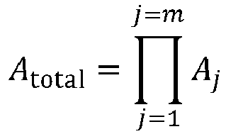
Durch die multiplikative Verknüpfung ist es möglich, relativ hohe Verstärkungsfaktoren von vorzugsweise 1...1000 zu erreichen und den Verstärker auf sehr kleinem Raum umzusetzen. Für den in ![]()
![]()

Um eine eingangsseitige translatorische Verschiebung auch ausgangsseitig wieder in eine rein translatorische Verschiebung zu wandeln, befinden sich am Ein- und Ausgang (2.1 und 2.2) des Verstärkers je ein Schubgelenk (2.3.3).In order to convert a translational shift on the input side into a purely translational shift also on the output side, there are each a sliding joint (2.3.3) at the input and output (2.1 and 2.2) of the amplifier.
Die Gelenke des mikrosystemtechnisch umgesetzten zweidimensionalen Verstärkungsmechanismus können in Form von Festkörpergelenken umgesetzt werden, um so Abrieb an der Gelenkachsen zu vermeiden. Auf Schubgelenke am Ein- und Ausgang kann in diesem Fall verzichtet werden, da durch die Rückstellkräfte der Festkörpergelenke und dem symmetrischen Aufbau des Mechanismus jegliche Querkräfte am Ein- oder Ausgang kompensiert werden. Eine eingangsseitig translatorische Verschiebung wird so in eine ebenfalls reine translatorische Verschiebung am Ausgang umgewandelt. Zusätzliche Schubgelenke sind daher optional bei der Verwendung von Festkörpergelenken.The joints of the two-dimensional reinforcement mechanism implemented using microsystem technology can be implemented in the form of solid body joints in order to avoid abrasion on the joint axes. In this case, there is no need for sliding joints at the entrance and exit, as the restoring forces of the solid-state joints and the symmetrical structure of the mechanism compensate for any transverse forces at the entrance or exit. A translational shift on the input side is thus converted into a likewise pure translational shift at the output. Additional sliding joints are therefore optional when using solid body joints.
Neben der Weg-Verstärkung lässt sich über den mechanischen Verstärker (2) auch die Eingangs- und Ausgangssteifigkeit des Verstärkers (2) einstellen. Als Eingangssteifigkeit c in wird hier das Verhältnis von Eingangskraft Fin zu Eingangsverschiebung y in am Ein- bzw. Ausgang definiert: ![]()
![]()
Und für die Ausgangssteifigkeit c out gilt entsprechend: ![]()
![]()
Die Steifigkeit am Verstärker wird durch die Steifigkeit ci der Festkörpergelenke sowie die Verstärkung der einzelnen Hebel bestimmt. Je steifer der Systemeingang, desto höher ist der Kraftaufwand, der aufgebracht werden muss, um das Eingangselement des Verstärkers zu verschieben.The rigidity of the booster is determined by the rigidity c i of the flexure joints and the reinforcement of the individual levers. The stiffer the system input, the greater the effort that has to be applied to move the input element of the amplifier.
Sollen wie in ![]()
![]()
Ist dies nicht gegeben, so ist der Kraftaufwand, der an der j-ten Hebelpaarung aufgebracht werden muss, verhältnismäßig hoch, sodass entweder das System zerstört wird oder sich die Festkörpergelenke oder die Hebel stark biegen, sodass die Genauigkeit der berechneten Ausgangsverschiebung nicht gegeben ist.If this is not the case, the force that must be applied to the j th lever pairing is relatively high, so that either the system is destroyed or the Bending solid joints or the levers sharply, so that the accuracy of the calculated output displacement is not given.
In einer bevorzugten Ausführungsform stellt die Verstärkung A total (y in) eine Funktion der Eingangsverschiebung y in dar. Die Funktion der Verstärkung A total(y in) kann dabei sowohl entsprechend ![]()
![]()
![]()
![]()
Auch eine quadratisch zunehmende Verstärkung der Form ![]()
![]()
Bei einer bevorzugten Ausführungsform werden hierzu am Hebelmechanismus mindestens eines der Gelenke, die den Hebelmechanismus mit dem Substrat verbinden, durch mindestens eine Kurvenscheibe (2.3.4) ersetzt, wobei die vordefinierte Übertragungsfunktion an der Kurvenscheibe (2.3.4) implementiert ist. Beim Auslenken des zugehörigen Hebels (2.3.1) wird dieser nicht um einen durch ein festes Gelenk definierten zum Substrat fixierten Punkt gedreht, sondern bewegt sich entlang der Kurvenscheibe (2.3.4). Da der Hebel an der Kurvenscheibe entlang gleitet, wandert auch der Drehpunkt in Abhängigkeit der Verschiebung, wodurch sich der zugehörige Abstand a oder b oder c oder d und damit die Verstärkung in Abhängigkeit der Verschiebung verändert, wie in
Die Aufgabe des elektromechanischen Wandlers (3) besteht darin, die Verschiebung am Ausgang des Verstärkers (2.2) in ein elektrisches Signal zu wandeln. Dafür gibt es verschiedene Möglichkeiten einer elektromechanischen Zustandserfassung. So lässt sich die Verschiebung beispielsweise über einen kapazitiven Wandler (3.3), wie in
Um auf eine aufwendige elektrische Schaltung zu verzichten, wird daher bevorzugt ein kontaktbasierter Wandler genutzt. In
Der Wandler umfasst n W gestellfeste und flexibel gelagerte Gegenelektroden (3.1.2) sowie dazu paarweise zugehörige Fingerelektrodengruppe (3.1.3). Die Fingerelektrodengruppen sind dabei am Läufer (8) des Dehnungssensors montiert und lassen sich translatorisch entlang der Läuferrichtung mit dem Läufer verschieben. Die Gegenelektroden sind hingegen gestellfest entlang der Fingerelektrodengruppen positioniert. Eine Fingerelektrodengruppe (3.1.3) umfasst eine oder mehrere Fingerelektroden (3.1.1), die dadurch gekennzeichnet sind, dass sie bei einer definierten translatorischen Auslenkung des Läufers einen elektrischen Kontakt mit den gestellfesten Gegenelektroden herstellen oder es zwischen Gegenelektroden und Fingerelektroden zu einer Impedanzänderung kommt, sobald sich beide Elektroden gegenüberstehen. Über die Anordnung der Elektroden wird die Position des Läufers eindeutig geometrisch codiert.The transducer comprises n W frame-fixed and flexibly mounted counter-electrodes (3.1.2) as well as finger electrode groups (3.1.3) belonging to them in pairs. The finger electrode groups are mounted on the runner (8) of the strain sensor and can be moved translationally along the runner direction with the runner. In contrast, the counter-electrodes are fixed to the frame along the finger electrode groups. A finger electrode group (3.1.3) comprises one or more finger electrodes (3.1.1), which are characterized in that they establish electrical contact with the counter-electrodes fixed to the frame or there is a change in impedance between the counter-electrodes and finger electrodes in the event of a defined translational deflection of the rotor as soon as both electrodes are facing each other. The position of the rotor is clearly geometrically coded through the arrangement of the electrodes.
Zur elektrischen Erfassung der diskreten Läuferposition wird am Läufer eine elektrische Spannung U 0 angelegt. Gleichzeitig wird die Spannung an den gestellfesten Gegenelektroden (3.1.2) gemessen bzw. abgegriffen. Solange sich die Gegenelektroden (3.1.2) und die Fingerelektroden (3.1.1) am Läufer nicht gegenüberstehen oder berühren, liegt an den Gegenelektroden ein erstes definiertes elektrisches Potential, beispielsweise 0 V an. Dieses definierte erste elektrische Potential wird z.B. über Pull-down oder Pull-up Widerstände an den gestellfesten Gegenelektroden gewährleistet. Wird nun der Läufer verschoben, sodass sich je eine Fingerelektrode und eine Gegenelektrode gegenüberstehen, so wird die am Läufer angelegte Spannung U 0 von den Fingerelektroden an die Gegenelektroden übertragen, sodass nun an der entsprechenden Gegenelektrode ein vom initialen Zustand verschiedenes zweites elektrisches Potential (idealerweise Uo) anliegt. Gleichzeitig fällt über dem zugehörigen Pull-up oder Pull-down Widerstand eine Spannung ab.
Der Abstand zwischen Fingerelektroden und Gegenelektroden kann einerseits überlappend gestaltet sein, sodass bei der Verschiebung der Fingerelektroden diese an den Gegenelektroden entlang gleiten. Eine solche Konfiguration wird beispielsweise in
In einer bevorzugten Ausführungsform können die Fingerelektrodengruppen (3.1.3) entweder seriell am Läufer (8) oder auch in einer Kammstruktur angeordnet sein, wie
Als Wandler können auch beispielsweise ein kapazitiver oder piezoresistiver Wandler genutzt werden.A capacitive or piezoresistive converter, for example, can also be used as the converter.
Neben einer direkten elektro-mechanischen Analog-Digital Wandlung ist auch eine binäre/digitale Positionserfassung mit Hilfe weiterer Übertragungsfunktionen möglich, die anstelle eines binär codierten Signals einen Thermometer-Code (z. B. 0001111) oder eine Dezimalzahl liefern. Hierzu wird die Codiereinheit des elektro-mechanischen Wandlers auf das entsprechende Zahlen- oder Codiersystem angepasst.
Ein besonderer Vorteil des elektro-mechanischen Wandlers in Form des mikromechanischen Analog-Digital Wandlers (3.1) besteht in der Diskretisierung und Digitalisierung einer Verschiebung in der mechanischen Domäne. Es werden keine weiteren aktiven elektrischen Bauelemente zur binären Codierung des Dehnungs- bzw. des Verschiebungssignals am Eingang des Wandlers benötigt. Durch die Möglichkeit einen geringen Abstand zwischen Finger- und Gegenelektroden einzustellen, wird die eigentliche Dehnungsmessung nur während der Auslesung des Wandlers (3.1) durch z.B. Reibung beeinflusst. Zudem werden für eine Signalauflösung von n Bit nur eine Anzahl von n Fingerelektrodengruppen (3.1.3) mit ggf. einem zusätzlichen Vorzeichenzweig (3.1.9) benötigt. Somit ist eine hohe Anzahl an Diskretisierungsschritten bei minimalem Platzbedarf möglich. Zudem lassen sich beliebige binäre Codes sowie beliebige Übertragungsfunktionen über die Anordnung und Größe der Fingerelektroden implementieren. Somit ist neben der passiven Digitalisierung auch bereits eine erste passive Datenaufbereitung durch Kennlinienanpassung über den Wandler möglich.A particular advantage of the electro-mechanical converter in the form of the micromechanical analog-digital converter (3.1) is the discretization and digitization of a shift in the mechanical domain. No further active electrical components are required for the binary coding of the expansion or displacement signal at the input of the converter. Due to the possibility of setting a small distance between the finger and counter electrodes, the actual strain measurement is only influenced by, for example, friction while the transducer (3.1) is reading. In addition, only a number of n finger electrode groups (3.1.3) with possibly an additional sign branch (3.1.9) are required for a signal resolution of n bits. This enables a large number of discretization steps with minimal space requirements. In addition, any binary codes and any transfer functions can be set via the arrangement and size of the finger electrodes to implement. Thus, in addition to passive digitization, an initial passive data preparation is already possible by adapting the characteristic curve via the converter.
Die Größe der Rastzähne sowie deren Abstände (a RZ) werden bei dieser Anordnung maßgeblich über die Auflösung der Lithografie während der Fertigung bestimmt. Je genauer die Fertigung, desto geringer lässt sich der Abstand a RZ umsetzen und desto geringer ist auch die Schrittweite y s zwischen den einzelnen Diskretisierungsschritten. Ferner wird der Reibwinkel γ an den Rastzähnen durch den Haftreibkoeffizienten zwischen den aneinander gleitenden Oberflächen limitiert. Durch den Abstand der einzelnen Rastzähne a RZ wird die minimale Schrittweite y s der diskretisierten Positionserfassung bestimmt. So gilt für die minimale Schrittweite y s von Rastposition zu Rastposition: ![]()
![]()
Um der Limitierung der minimalen Schrittweite y s entgegenzuwirken, kann der mechanische Speicher um zusätzliche Rastmechanismen-Paare bestehend aus Rastelementen und Sperrklingen ergänzt werden, wie in
Werden insgesamt n Paare bestehend aus je einem Rastelement und mindestens einer Sperrklinge vorgesehen, so gilt für den initialen Abstand b RZ,i zwischen Sperrklinge und erstem Rastzahn des i-ten Rastelements: ![]()
![]()
Dabei ist a offset ein fertigungsbedingter Offset, der für alle n Paare identisch sein sollte.Here, a offset is a production-related offset that should be identical for all n pairs.
Ist die Anzahl der Rastzähne k pro Rastelement für alle n Rastelemente identisch, so gilt für die Anzahl der speicherbaren Positionen z: ![]()
![]()
Inklusive der ersten initialen Position des Läufers können folglich insgesamt z Positionszustände gespeichert werden. Die minimale Schrittweite y s beträgt dann: ![]()
![]()
![]()
![]()
Die Größe der Rastzähne sowie deren Abstände werden maßgeblich über die Auflösung der Lithografie bestimmt. Ferner wird der Reibwinkel an den Rastzähnen durch den Haftreibkoeffizienten zwischen den aneinander gleitenden Oberflächen limitiert. Da der Abstand der Rastzähne die Schrittweite a RZ der diskreten Schritte und damit die Auflösung des Speichers limitiert, können weitere Rastmechanismen im System ergänzt werden, die jedoch um a RZ/n versetzt sind. Auf diese Weise können die Rastzähne auch Zwischenpositionen unabhängig von der lithografischen Auflösung einnehmen.The size of the ratchet teeth and their spacing are largely determined by the resolution of the lithography. Furthermore, the friction angle on the ratchet teeth is limited by the coefficient of static friction between the surfaces sliding against one another. Since the distance between the ratchet teeth limits the step size a RZ of the discrete steps and thus the resolution of the memory, further ratchet mechanisms can be added to the system, but these are offset by a RZ / n . In this way, the ratchet teeth can also assume intermediate positions regardless of the lithographic resolution.
Zum Zurücksetzen des mechanischen Maximalwertspeichers müssen die Sperrklingen (4.2) von den Rastzähnen (4.3) gelöst werden. Hierzu können verschiedene konventionelle Aktoren der Mikrosystemtechnik eingesetzt werden. In
Der Rückstellmechanismus ist über eine Rückstellkupplung (5.2) mit dem Rastmechanismus bzw. den Sperrklingen verbunden. Die Rückstellkupplung hat die Aufgabe, die Bewegungen der Sperrklingen, die beim Speichervorgang auftreten, von dem Rückstellmechanismus unidirektional zu entkoppeln, jedoch gleichzeitig die Verschiebungs- und Kraftaufwendungen des Aktors an den Rastmechanismus insbesondere an die Sperrklingen weiterzuleiten, um die Sperrklingen von den Rastzähnen zu lösen. Ferner sorgen Überträger (5.4) für die Verteilung der Kraft- und Verschiebungsübertragung vom Aktor auf alle zu lösenden Sperrklingen (4.2).The reset mechanism is connected to the locking mechanism or the locking blades via a reset clutch (5.2). The task of the reset clutch is to unidirectionally decouple the movements of the pawl blades that occur during the storage process from the reset mechanism, but at the same time to pass on the displacement and force exerted by the actuator to the locking mechanism, in particular to the pawl blades, in order to release the pawl blades from the locking teeth. Furthermore, carriers (5.4) ensure the distribution of the force and displacement transmission from the actuator to all locking blades to be released (4.2).
Der mechanische Maximalwertspeicher kann auch in Verbindung mit einer Kupplung (6) ausgebildet werden. Wird der erreichte Maximalwert durch den Rastmechanismus gespeichert, so ist der Läufer (8) dauerhaft ausgelenkt. Entspannt sich dann jedoch das zu überwachende Bauelement oder wird dieses in die entgegengesetzte Richtung beansprucht, so wirkt auf den Läufer (8) und damit auch an den Rastzähnen eine hohe Kraft, die den Mechanismus zerstören könnte. Aus diesem Grund kann der Maximalwertspeicher (4) mechanisch vom Verbindungselement (1a, 1b) über eine Kupplung (6) entkoppelt werden.The mechanical maximum value memory can also be designed in connection with a clutch (6). If the maximum value reached is saved by the locking mechanism, the rotor (8) is permanently deflected. If, however, the component to be monitored then relaxes or is stressed in the opposite direction, a high force acts on the rotor (8) and thus also on the ratchet teeth, which could destroy the mechanism. For this reason, the maximum value memory (4) can be mechanically decoupled from the connecting element (1a, 1b) via a coupling (6).
Im einfachsten Fall kann die Kupplung aus zwei gegenüberliegenden, mechanisch getrennten Stößeln bestehen, wie in
Das mikromechanische Messsystem kann alternativ oder in Ergänzung zur Dehnungsmessung auch zur energieautarken Messung weiterer physikalischer Größen genutzt werden. Vorzugsweise wird dazu das flexibel gelagerte Verbindungselement (1a) nicht direkt mit einem zu Dehnenden Prüfobjekt (12) verbunden, sondern alternativ mit einem mechanischen Eingangswandler (16), der dazu ausgeführt ist eine zu messende physikalische Größe in eine Verschiebungs- oder Dehnungsgröße zu wandeln die wiederum eine relative Verschiebung zwischen gestellfestem (1b) und flexiblen Verbindungselemente (1a) hervorruft.
Neben des gezeigten Beispiels für die Montage, Anordnung und Ausführung mechanischer Eingangswandler (16) am mikromechanischen Messsystem sind auch weitere Ausführungsformen des mechanischen Eingangswandlers (16) für alternative physikalische Messgrößen wie beispielsweise Temperatur, Strom, Spannung, Feuchtigkeit, elektrische oder magnetische Feldstärken denkbar. Insbesondere zur Erfassung von Feldgrößen ist die Nutzung magnetischer, dielektrische Materialien oder Elektret am flexibel gelagerten Verbindungselement (1a) als mechanischer Eingangswandler (16) denkbar. Zur Erfassung von Strom und Spannung kommen aus dem Stand der Technik bekannte elektrostatische oder elektrothermische Aktoren der Mikrosystemtechnik in Frage. Zur Erfassung von Temperaturen können Bi-Morphe oder Aktoren aus Formgedächtnislegierung zwischen flexibel gelagerten Verbindungselement und Gestell implementiert werden.The micromechanical measuring system can alternatively or in addition to the strain measurement also be used for energy self-sufficient measurement of further physical quantities. For this purpose, the flexibly mounted connecting element (1a) is preferably not connected directly to a test object (12) to be stretched, but alternatively to a mechanical input transducer (16), which is designed to convert a physical variable to be measured into a displacement or expansion variable in turn causes a relative displacement between the frame-fixed (1b) and flexible connecting elements (1a).
In addition to the example shown for the assembly, arrangement and design of mechanical input transducers (16) on the micromechanical measuring system, other embodiments of the mechanical input transducer (16) for alternative physical measured variables such as temperature, current, voltage, humidity, electrical or magnetic field strengths are also conceivable. The use of magnetic, dielectric materials or electret on the flexibly mounted connecting element (1a) as a mechanical input transducer (16) is conceivable in particular for the detection of field variables. Electrostatic or electrothermal actuators from microsystem technology known from the prior art can be used to detect current and voltage. Bi-Morphe or actuators made of shape memory alloy can be implemented between the flexibly mounted connecting element and the frame to record temperatures.
Das technische Prinzip des Dehnungsmesssystems lässt sich mit verschiedenen Technologien umsetzen, insbesondere mit Prozessen der Mikrosystemtechnik.The technical principle of the strain measuring system can be implemented with various technologies, in particular with processes of microsystem technology.
Besonders geeignet ist die technologische Umsetzung auf Basis eines SOI-Substrates ("Siliconon-Insulator"). Diese Substrate umfassen drei Schichten: einen sog. "Devicelayer", bestehend aus oder enthaltend einkristallines Silicium (15.1), einen "Buried Oxide Layer" (BOX-Layer) aus SiO2 (15.2) und eine weitere Schicht bestehend aus oder enthaltend einkristallinem Silicium, dem "Handellayer" (15.3).The technological implementation based on an SOI substrate ("siliconon insulator") is particularly suitable. These substrates comprise three layers: a so-called “device layer”, consisting of or containing monocrystalline silicon (15.1), a “buried oxide layer” (BOX layer) made of SiO 2 (15.2) and a further layer consisting of or containing monocrystalline silicon , the "handelayer" (15.3).
Der Devicelayer (15.1) trägt die frei beweglichen, zweidimensionalen mechanischen Strukturen wie beispielsweise den mechanischen Verstärker (2) oder den Maximalwertspeicher (4), während der Handlelayer (15.3) als mechanisches Gestell verstanden werden kann, der über die SiO2-Schicht des BOX-Layers (15.2) mit den mechanischen Strukturen des Devicelayers an fest definierten Stellen verbunden ist. Der BOX-Layer (15.2) bildet dabei eine Opferschicht, die unterhalb der frei beweglichen Strukturen partiell entfernt wird.The device layer (15.1) carries the freely movable, two-dimensional mechanical structures such as the mechanical amplifier (2) or the maximum value memory (4), while the handle layer (15.3) can be understood as a mechanical frame that is placed over the SiO 2 layer of the BOX -Layers (15.2) is connected to the mechanical structures of the device layer at firmly defined points. The BOX layer (15.2) forms a sacrificial layer that is partially removed below the freely movable structures.
Zur Fertigung des Dehnungsmesssystems (10) wird sowohl der Devicelayer (15.1) als auch der Handlelayer (15.3) strukturiert. Im Devicelayer (15.1) werden die gesamten mechanischen und elektromechanischen Komponenten realisiert, während am Handlelayer (15.3) die Verbindungselemente (1a, 1b) vorgesehen sind, die den Sensor mit einem Messobjekt (12) oder einem flexiblen Gehäuse (11) verbinden. Alternativ können die Verbindungselemente auch am Devicelayer angebracht sein. Handle- und Devicelayer sind über den BOX-Layer (15.2) verbunden, so dass die mechanische Verschiebung an den Verbindungselementen auf den Devicelayer übertragen werden kann. In
Der genaue Fertigungsablauf kann variieren. Ein grundsätzlicher Prozessablauf wird in
Ausgangspunkt für den Fertigungsablauf ist ein SOI Substrat bzw. ein Substrat bestehend aus drei Ebenen wobei die mittlere Ebene (15.2) eine Opferschicht darstellt, die Devicelayer Ebene (15.1) die Funktionsschicht und die Handlelayer Ebene (15.3) die Aufgabe des mechanischen Gestells (13) übernimmt (
Damit beim Fügen des Sensors mit einem Messobjekt durch z.B. Löten nur die definierten Verbindungsstellen mit Lot benetzt werden und nicht etwa der gesamte Chip, werden die Oberflächen der Verbindungselemente (1a, 1b) zusätzlich modifiziert, wie z.B. durch Abscheidung eines Verbundmaterials (15.5) (
Auf der Vorderseite des SOI-Wafers, also auf dem Devicelayer (15.1), wird über einen weiteren Lithografie-Prozess die Geometrie der mechanischen Komponenten des Sensors (Verstärker, ggfs. Maximalwertspeicher, ggfs. elektromechanischer Wandler, etc.) auf den Devicelayer (15.1) projiziert. Der Devicelayer (15.1) wird anschließend über reaktives Ionentiefätzen ("DRIE"-Prozess) durchgehend bis zur nächsten Schicht tiefgeätzt (
Alternativ zur Fertigung über ein SOI-Substrat ist auch die Fertigung mit Hilfe eines mehrschichtigen Aufbaus von Keramik- oder Metall-Schichten denkbar. Dabei werden die für die Funktion notwendigen Funktionsschichten (gestellfeste Ebene - Handlelayer, Ebene für frei bewegliche Elemente - Devicelayer) anstelle von Silicium durch eine Keramik oder Metallschicht umgesetzt. Auf diese Weise können Materialien verwendet werden, deren thermischer Längenausdehnungskoeffizient zum Ausdehnungskoeffizienten des Messobjektes passen. Alternativ können Materialien wie die Glaskeramiken (z.B. Zerodur) mit besonders niedrigen thermischen Ausdehnungskoeffizienten verwendet werden.As an alternative to production using an SOI substrate, production using a multilayer structure of ceramic or metal layers is also conceivable. The functional layers necessary for the function (frame-fixed level - handlayer, level for freely movable elements - device layer) are implemented with a ceramic or metal layer instead of silicon. In this way, materials can be used whose thermal coefficient of linear expansion matches the coefficient of expansion of the measurement object. Alternatively, materials such as glass ceramics (e.g. Zerodur) with particularly low thermal expansion coefficients can be used.
- 1a:1a:
- flexibel gelagertes Verbindungselementflexibly mounted connecting element
- 1b:1b:
- gestellfest gelagertes VerbindungselementFrame-mounted connecting element
- 1c:1c:
- Verbindungselement für KompensationsmechanismusConnection element for compensation mechanism
- 1d:1d:
- Verbindungselement für KompensationsmechanismusConnection element for compensation mechanism
- 2:2:
- mechanischer Verstärkermechanical amplifier
- 2.1:2.1:
- VerstärkereingangAmplifier input
- 2.2:2.2:
- VerstärkerausgangAmplifier output
- 2.3.1:2.3.1:
- Hebellever
- 2.3.2:2.3.2:
- HebelverbinderLever connector
- 2.3.3:2.3.3:
- SchubgelenkSliding joint
- 2.3.4:2.3.4:
- KurvenschreibeCurve chart
- 2.3.5:2.3.5:
- DrehgelenkSwivel joint
- 2.3.6:2.3.6:
- gestellfestes Drehgelenkframe-mounted swivel joint
- 2.4:2.4:
- Erste HebelpaarungFirst pair of levers
- 2.5:2.5:
- j-te Hebelpaarung j th lever pairing
- 2.6:2.6:
- m-te Hebelpaarung (hinterste Hebelpaarung in der seriellen Anordnung an Hebelpaarungen)m-th lever pairing (rearmost lever pairing in the serial arrangement of lever pairings)
- 3:3:
- elektro-mechanischer Wandlerelectro-mechanical converter
- 3.1:3.1:
- mikromechanischer Analog-Digital Wandlermicromechanical analog-digital converter
- 3.2:3.2:
- mikromechanische Positionsschaltermicromechanical position switches
- 3.3:3.3:
- kapazitiver Wandlercapacitive converter
- 3.4:3.4:
- kontaktbasierter mikromechanischer A/D Wandler mit DezimalkodierungContact-based micromechanical A / D converter with decimal coding
- 3.1.1:3.1.1:
- Fingerelektroden montiert an LäuferFinger electrodes mounted on the runner
- 3.1.2:3.1.2:
- Gegenelektroden (gestellfest)Counter electrodes (fixed to frame)
- 3.1.3:3.1.3:
- FingerelektrodengruppenFinger electrode groups
- 3.1.4:3.1.4:
- Federaufhängung GegenelektrodeSpring suspension counter electrode
- 3.1.5:3.1.5:
- Pull-down/Pull-up WiderstandPull-down / pull-up resistance
- 3.1.6:3.1.6:
- Spannungsquelle oder SpannungsanschlussVoltage source or voltage connection
- 3.1.7:3.1.7:
-
Spannungsabgriff an Bit 0Voltage tap on
bit 0 - 3.1.8:3.1.8:
-
Spannungsabgriff an Bit 1Voltage tap on
bit 1 - 3.1.9:3.1.9:
- Vorzeichenzweig zur Codierung der DehnungsrichtungSign branch for coding the stretching direction
- 3.3.1:3.3.1:
- gestellfeste Elektrodenfixed electrodes
- 3.3.2:3.3.2:
- bewegliche Elektrodenmovable electrodes
- 3.4.1:3.4.1:
-
Kodiereinheit zur Kodierung der Dezimalstellen 100 Coding unit for coding the
decimal places 10 0 - 3.4.2:3.4.2:
-
Kodiereinheit zur Kodierung der Dezimalstellen 101 Coding unit for coding the
decimal places 10 1 - 4:4:
- mechanischer Maximalwertspeichermechanical maximum value memory
- 4.1:4.1:
- RastelementeLocking elements
- 4.1.1:4.1.1:
- erste Rastelement mit k Rastzähnen (Ausführungsbeispiel)first locking element with k locking teeth (exemplary embodiment)
- 4.1.2:4.1.2:
- (n-1)-tes Rastelement mit z.B. k Rastzähnen (Ausführungsbeispiel)(n-1) -th locking element with e.g. k locking teeth (exemplary embodiment)
- 4.1.3:4.1.3:
- n-tes Rastelement mit z.B. k Rastzähnennth locking element with e.g. k locking teeth
- 4.2:4.2:
- SperrklingenPawls
- 4.2.1:4.2.1:
- erste Sperrklinge zugehörig zu erstem Rastelementfirst locking blade belonging to the first locking element
- 4.2.2:4.2.2:
- (n-1)-te Sperrklinge zugehörig zu (n-1)-tem Rastelement(n-1) -th locking blade belonging to (n-1) -th locking element
- 4.2.3:4.2.3:
- n-te Sperrklinge zugehörig zu n-tem Rastelementn-th lock blade belonging to n -th latching element
- 4.3:4.3:
- Einzelner Rastzahn an RastelementSingle locking tooth on locking element
- 5:5:
- RückstellmechanismusReset mechanism
- 5.1:5.1:
- elektrostatischer Aktorelectrostatic actuator
- 5.2:5.2:
- RückstellkupplungReset clutch
- 5.3:5.3:
- Führungsfeder RückstellmechanismusGuide spring return mechanism
- 5.4:5.4:
- Überträger (Rückstellmechanismus)Carrier (reset mechanism)
- 6:6:
- Kupplungcoupling
- 6.1:6.1:
- erster Stößelfirst ram
- 6.2:6.2:
- zweiter Stößelsecond ram
- 7:7:
- FührungsfedernGuide springs
- 8:8th:
- Läuferrunner
- 10:10:
- DehnungssensorStrain sensor
- 11:11:
- flexibles Gehäuseflexible housing
- 12:12:
- Prüfobjekt, Prüfkörper, MessobjektTest object, test body, measurement object
- 13:13:
- Substrat/ Gestell des DehnungssensorsSubstrate / frame of the strain sensor
- 14:14:
- BondelektrodenBonding electrodes
- 15.1:15.1:
- Substratebene beinhaltend den mechanischen Aufbau, Devicelayer (vorzugsweise Silicium)Substrate level including the mechanical structure, device layer (preferably silicon)
- 15.2:15.2:
- Substratebene beinhaltend eine Opferschicht, BOX-Layer (vorzugsweise SiO2)Substrate level including a sacrificial layer, BOX layer (preferably SiO 2 )
- 15.3:15.3:
- Substratebene beinhaltend das mechanische Gestell, Handlelayer (vorzugsweise Silicium)Substrate level including the mechanical frame, hand layer (preferably silicon)
- 15.4:15.4:
- Elektrodenmaterial (vorzugsweise Aluminium, Titan, Nickel, Chrom oder Gold)Electrode material (preferably aluminum, titanium, nickel, chromium or gold)
- 15.5:15.5:
- Verbindungsmaterial zum stoffschlüssigen Verbund zwischen Dehnungssensor und Messobjekt (vorzugsweise Klebstoff, Lot, reaktive Metallschichten)Connection material for a material bond between the strain sensor and the measurement object (preferably adhesive, solder, reactive metal layers)
- 15.6:15.6:
- Vom Dehnungssensor auf das Gehäuse herausgeführte ElektrodenElectrodes led out from the strain sensor onto the housing
- 15.7:15.7:
- Substrat des flexiblen Gehäuses (vorzugsweise Glas, Glaskeramik, Keramik, Silicium)Substrate of the flexible housing (preferably glass, glass ceramic, ceramic, silicon)
- 16:16:
- mechanischer Eingangswandlermechanical input transducer
- 16.1:16.1:
- seismische Prüfmasseseismic proof mass
- 17:17:
- KompensationsmechanismusCompensation mechanism
- 17.1:17.1:
- Krafttransformator, FederPower transformer, spring
- 17.2:17.2:
- UmlenkmechanismusReversing mechanism
Claims (18)
Speicherung des erreichten Maximalwerts der Dehnung in einem mechanischen Maximalwertspeicher.Method for measuring according to claim 14 or 15, comprising the following further step between said steps (iii) and (iv):
Storage of the reached maximum value of the elongation in a mechanical maximum value memory.
Trennung von sich überlagernder isotrop wirkender Dehnung von axial wirkender Dehnung über einen Kompensationsmechanismus und selektive Übertragung der axial wirkenden Dehnung an den mechanischen Verstärker.Method for measurement according to claims 14-17, comprising the following further step between said steps (i) and (ii):
Separation of overlapping isotropically acting strains from axially acting strains via a compensation mechanism and selective transmission of the axially acting strains to the mechanical amplifier.
Priority Applications (2)
| Application Number | Priority Date | Filing Date | Title |
|---|---|---|---|
| EP24153205.0A EP4336143A2 (en) | 2019-11-18 | 2020-11-17 | Micromechanical measuring system for measuring strain on a measurement object and compensating for isotropically acting strain |
| EP24153189.6A EP4354082A2 (en) | 2019-11-18 | 2020-11-17 | Micromechanical device for the self-powered measurement and storage of a mechanical displacement signal |
Applications Claiming Priority (1)
| Application Number | Priority Date | Filing Date | Title |
|---|---|---|---|
| DE102019131094 | 2019-11-18 |
Related Child Applications (2)
| Application Number | Title | Priority Date | Filing Date |
|---|---|---|---|
| EP24153205.0A Division EP4336143A2 (en) | 2019-11-18 | 2020-11-17 | Micromechanical measuring system for measuring strain on a measurement object and compensating for isotropically acting strain |
| EP24153189.6A Division EP4354082A2 (en) | 2019-11-18 | 2020-11-17 | Micromechanical device for the self-powered measurement and storage of a mechanical displacement signal |
Publications (2)
| Publication Number | Publication Date |
|---|---|
| EP3822577A1 true EP3822577A1 (en) | 2021-05-19 |
| EP3822577B1 EP3822577B1 (en) | 2024-01-24 |
Family
ID=73475883
Family Applications (3)
| Application Number | Title | Priority Date | Filing Date |
|---|---|---|---|
| EP24153189.6A Pending EP4354082A2 (en) | 2019-11-18 | 2020-11-17 | Micromechanical device for the self-powered measurement and storage of a mechanical displacement signal |
| EP24153205.0A Pending EP4336143A2 (en) | 2019-11-18 | 2020-11-17 | Micromechanical measuring system for measuring strain on a measurement object and compensating for isotropically acting strain |
| EP20208176.6A Active EP3822577B1 (en) | 2019-11-18 | 2020-11-17 | Micromechanical deformation measurement system, associated manufacturing and measurement processes |
Family Applications Before (2)
| Application Number | Title | Priority Date | Filing Date |
|---|---|---|---|
| EP24153189.6A Pending EP4354082A2 (en) | 2019-11-18 | 2020-11-17 | Micromechanical device for the self-powered measurement and storage of a mechanical displacement signal |
| EP24153205.0A Pending EP4336143A2 (en) | 2019-11-18 | 2020-11-17 | Micromechanical measuring system for measuring strain on a measurement object and compensating for isotropically acting strain |
Country Status (1)
| Country | Link |
|---|---|
| EP (3) | EP4354082A2 (en) |
Cited By (3)
| Publication number | Priority date | Publication date | Assignee | Title |
|---|---|---|---|---|
| WO2024056571A1 (en) * | 2022-09-13 | 2024-03-21 | Zf Friedrichshafen Ag | Connection of a sensor assembly, arranged on a mounting plate, to a measurement object |
| WO2024056573A1 (en) * | 2022-09-13 | 2024-03-21 | Zf Friedrichshafen Ag | Connection of a sensor assembly, arranged on a mounting plate, to a measurement object |
| WO2024056572A1 (en) * | 2022-09-13 | 2024-03-21 | Zf Friedrichshafen Ag | Connecting a sensor assembly arranged on a mounting plate to a device under test |
Citations (11)
| Publication number | Priority date | Publication date | Assignee | Title |
|---|---|---|---|---|
| DE69822097T2 (en) | 1997-11-28 | 2004-10-21 | Sarcos Inc | Strain sensor and its use |
| WO2005068960A1 (en) * | 2004-01-05 | 2005-07-28 | Case Western Reserve University | Capacitive strain sensors |
| DE10214984B4 (en) | 2002-04-04 | 2006-01-19 | Eads Deutschland Gmbh | Actuator and sensor system for composite structures |
| US20090139342A1 (en) * | 2007-11-30 | 2009-06-04 | Philippe Robert | Device with detection by suspended piezoresistive strain gauge comprising a strain amplifier cell |
| DE102010038062B9 (en) | 2010-10-08 | 2013-08-22 | Messphysik Materials Testing Gmbh | Location determination and determination of the displacement of places by non-contact distance measurement in a material test |
| DE102014004544A1 (en) | 2013-04-15 | 2014-10-16 | Tracto-Technik Gmbh & Co. Kg | "Rod magazine" |
| US20150022053A1 (en) * | 2012-01-12 | 2015-01-22 | Silmach | Passive indexing of a movable element having teeth |
| EP2294374B1 (en) | 2008-06-12 | 2015-02-18 | Hottinger Baldwin Messtechnik GmbH | Optical extension sensor |
| DE102015002452A1 (en) | 2015-02-25 | 2016-08-25 | Kiekert Aktiengesellschaft | Motor vehicle lock |
| DE102016202769A1 (en) | 2016-02-23 | 2017-08-24 | Technische Universität Dresden | Sensor for integral or spatially resolved strain measurement based on pre-damaged carbon fibers |
| EP2705330B1 (en) | 2011-04-22 | 2019-01-02 | Etat français représenté par le Délégué Général pour l'Armement | Passive, reversible deformation sensor |
-
2020
- 2020-11-17 EP EP24153189.6A patent/EP4354082A2/en active Pending
- 2020-11-17 EP EP24153205.0A patent/EP4336143A2/en active Pending
- 2020-11-17 EP EP20208176.6A patent/EP3822577B1/en active Active
Patent Citations (11)
| Publication number | Priority date | Publication date | Assignee | Title |
|---|---|---|---|---|
| DE69822097T2 (en) | 1997-11-28 | 2004-10-21 | Sarcos Inc | Strain sensor and its use |
| DE10214984B4 (en) | 2002-04-04 | 2006-01-19 | Eads Deutschland Gmbh | Actuator and sensor system for composite structures |
| WO2005068960A1 (en) * | 2004-01-05 | 2005-07-28 | Case Western Reserve University | Capacitive strain sensors |
| US20090139342A1 (en) * | 2007-11-30 | 2009-06-04 | Philippe Robert | Device with detection by suspended piezoresistive strain gauge comprising a strain amplifier cell |
| EP2294374B1 (en) | 2008-06-12 | 2015-02-18 | Hottinger Baldwin Messtechnik GmbH | Optical extension sensor |
| DE102010038062B9 (en) | 2010-10-08 | 2013-08-22 | Messphysik Materials Testing Gmbh | Location determination and determination of the displacement of places by non-contact distance measurement in a material test |
| EP2705330B1 (en) | 2011-04-22 | 2019-01-02 | Etat français représenté par le Délégué Général pour l'Armement | Passive, reversible deformation sensor |
| US20150022053A1 (en) * | 2012-01-12 | 2015-01-22 | Silmach | Passive indexing of a movable element having teeth |
| DE102014004544A1 (en) | 2013-04-15 | 2014-10-16 | Tracto-Technik Gmbh & Co. Kg | "Rod magazine" |
| DE102015002452A1 (en) | 2015-02-25 | 2016-08-25 | Kiekert Aktiengesellschaft | Motor vehicle lock |
| DE102016202769A1 (en) | 2016-02-23 | 2017-08-24 | Technische Universität Dresden | Sensor for integral or spatially resolved strain measurement based on pre-damaged carbon fibers |
Non-Patent Citations (10)
| Title |
|---|
| CHEN, C ET AL.: "Femtosecond Laser-Inscribed High-Order Bragg Gratings in Large-Diameter Sapphire Fibers for High-Temperature and Strain Sensing", JOURNAL OF LIGHTWAVE TECHNOLOGY, 2018 |
| EXPERIMENTELLE STRUKTURANALYSE DEHNUNGSMESSSTREIFEN MIT METALLISCHEM MESSGITTER KENNGRÖSSEN UND PRÜFBEDINGUNGEN, July 2015 (2015-07-01) |
| EXPERIMENTELLE STRUKTURANALYSE EMPFEHLUNG ZUR DURCHFÜHRUNG VON DEHNUNGSMESSUNGEN BEI HOHEN TEMPERATUREN, February 2015 (2015-02-01) |
| GERLACH, GW. DÖTZEL: "Einführung in die Mikrosystemtechnik ein Kursbuch für Studierende", 2006, FACHBUCHVERL. LEIPZIG IM CARL HANSER VERL, pages: 384 |
| MEHNER HANNES ET AL: "Passive microsensor for binary counting of numerous threshold events", PROCEEDINGS OF SPIE, IEEE, US, vol. 9517, 20 May 2015 (2015-05-20), pages 95170Z - 95170Z, XP060055561, ISBN: 978-1-62841-730-2, DOI: 10.1117/12.2178726 * |
| PHILIP SCHMITT ET AL: "A Micromechanical Binary Counter with MEMS-Based Digital-to-Analog Converter", PROCEEDINGS, vol. 2, no. 13, 21 November 2018 (2018-11-21), pages 807, XP055754777, DOI: 10.3390/proceedings2130807 * |
| SCHOMBURG, W.K.: "Introduction to Microsystem Design", 2011, SPRINGER |
| TIAN, Q. H.YAN, L. P.YANG, T.CHEN, B. Y.: "Applied Mechanics and Materials", vol. 117, 2012, TRANS TECH PUBLICATIONS, article "Recent Developments of Material Deformation Measurement", pages: 122 - 128 |
| TIETZE, U.C. SCHENKE. GAMM: "Halbleiter-Schaltungstechnik", 2012, SPRINGER-VERLAG |
| XINYU LIU ET AL: "A millimeter-sized nanomanipulator with sub-nanometer positioning resolution and large force output", SMART MATERIALS AND STRUCTURES, IOP PUBLISHING LTD., BRISTOL, GB, vol. 16, no. 5, 1 October 2007 (2007-10-01), pages 1742 - 1750, XP020120586, ISSN: 0964-1726, DOI: 10.1088/0964-1726/16/5/029 * |
Cited By (3)
| Publication number | Priority date | Publication date | Assignee | Title |
|---|---|---|---|---|
| WO2024056571A1 (en) * | 2022-09-13 | 2024-03-21 | Zf Friedrichshafen Ag | Connection of a sensor assembly, arranged on a mounting plate, to a measurement object |
| WO2024056573A1 (en) * | 2022-09-13 | 2024-03-21 | Zf Friedrichshafen Ag | Connection of a sensor assembly, arranged on a mounting plate, to a measurement object |
| WO2024056572A1 (en) * | 2022-09-13 | 2024-03-21 | Zf Friedrichshafen Ag | Connecting a sensor assembly arranged on a mounting plate to a device under test |
Also Published As
| Publication number | Publication date |
|---|---|
| EP3822577B1 (en) | 2024-01-24 |
| EP4336143A2 (en) | 2024-03-13 |
| EP4354082A2 (en) | 2024-04-17 |
Similar Documents
| Publication | Publication Date | Title |
|---|---|---|
| EP3822577B1 (en) | Micromechanical deformation measurement system, associated manufacturing and measurement processes | |
| EP2013598B1 (en) | Force-sensing device for measuring force on solid state actuators, method for measuring force, as well as use of force-sensing device | |
| EP1460398B1 (en) | Strain sensor with resistive and piezoelectric strain-sensitive elements | |
| EP3870930B1 (en) | Elongation measuring structure with a structured support | |
| EP2998777B1 (en) | Piezoelectric position sensor for piezoelectric driven resonant micromirror | |
| WO2006072391A1 (en) | Force measuring device, especially pressure gauge, and associated production method | |
| EP0494143B1 (en) | Device for measuring mechanical forces and dynamic effects | |
| EP1612531A2 (en) | Micro- mechanical structure | |
| DE10336232B4 (en) | Capacitive sensor for dynamic quantities | |
| DE102007032175A1 (en) | Piezoelectric actuator and scanning microscope using such | |
| CN114001639A (en) | Four-strain-gap four-resistance-gate type thin film strain sensor and preparation method thereof | |
| WO2007054374A1 (en) | Measurement of stress in coatings using a piezoelectric actuator | |
| DE60125815T2 (en) | DEVICE FOR MEASURING MICROWAVES AND METHOD FOR CONVERTING THE MOVEMENTS TO AN ELECTRICAL SIGNAL | |
| EP4302059A1 (en) | Device for measuring deformations, stresses, forces and/or torques in a plurality of axes | |
| DE4309530C2 (en) | Device for the dynamic mechanical analysis of test specimens | |
| DE102010054970B4 (en) | Device for converting an expansion and / or compression into an electrical signal, in particular a strain gauge film | |
| DE102008063797B4 (en) | gauge | |
| Norouzi et al. | Design of piezoelectric microcantilever chemical sensors in COMSOL multiphysics area | |
| EP1834162B1 (en) | Microsystem component with a device deformable under the influence of temperature changes | |
| DE19857124C2 (en) | Force sensor system | |
| DE102011006922B4 (en) | Instrument transformers for sensor technology | |
| DE102011105539B4 (en) | Device for converting a force into an electrical signal, in particular piezoresistive force sensor | |
| EP1288646B1 (en) | Method and apparatus for measuring a material property | |
| DE102017223831A1 (en) | Stretching strip comprising a flexible substrate and a resistance layer and sensor element comprising a strain gauge | |
| DE102011106894B3 (en) | Apparatus for simultaneous measurement of force and moment components, has deformable element that is provided with rod-shaped movable elements with bending joints and edges in cuboid form |
Legal Events
| Date | Code | Title | Description |
|---|---|---|---|
| PUAI | Public reference made under article 153(3) epc to a published international application that has entered the european phase |
Free format text: ORIGINAL CODE: 0009012 |
|
| STAA | Information on the status of an ep patent application or granted ep patent |
Free format text: STATUS: THE APPLICATION HAS BEEN PUBLISHED |
|
| AK | Designated contracting states |
Kind code of ref document: A1 Designated state(s): AL AT BE BG CH CY CZ DE DK EE ES FI FR GB GR HR HU IE IS IT LI LT LU LV MC MK MT NL NO PL PT RO RS SE SI SK SM TR |
|
| STAA | Information on the status of an ep patent application or granted ep patent |
Free format text: STATUS: REQUEST FOR EXAMINATION WAS MADE |
|
| 17P | Request for examination filed |
Effective date: 20211105 |
|
| RBV | Designated contracting states (corrected) |
Designated state(s): AL AT BE BG CH CY CZ DE DK EE ES FI FR GB GR HR HU IE IS IT LI LT LU LV MC MK MT NL NO PL PT RO RS SE SI SK SM TR |
|
| GRAP | Despatch of communication of intention to grant a patent |
Free format text: ORIGINAL CODE: EPIDOSNIGR1 |
|
| STAA | Information on the status of an ep patent application or granted ep patent |
Free format text: STATUS: GRANT OF PATENT IS INTENDED |
|
| INTG | Intention to grant announced |
Effective date: 20230315 |
|
| GRAJ | Information related to disapproval of communication of intention to grant by the applicant or resumption of examination proceedings by the epo deleted |
Free format text: ORIGINAL CODE: EPIDOSDIGR1 |
|
| STAA | Information on the status of an ep patent application or granted ep patent |
Free format text: STATUS: REQUEST FOR EXAMINATION WAS MADE |
|
| INTC | Intention to grant announced (deleted) | ||
| GRAP | Despatch of communication of intention to grant a patent |
Free format text: ORIGINAL CODE: EPIDOSNIGR1 |
|
| STAA | Information on the status of an ep patent application or granted ep patent |
Free format text: STATUS: GRANT OF PATENT IS INTENDED |
|
| INTG | Intention to grant announced |
Effective date: 20230912 |
|
| GRAS | Grant fee paid |
Free format text: ORIGINAL CODE: EPIDOSNIGR3 |
|
| GRAA | (expected) grant |
Free format text: ORIGINAL CODE: 0009210 |
|
| STAA | Information on the status of an ep patent application or granted ep patent |
Free format text: STATUS: THE PATENT HAS BEEN GRANTED |
|
| P01 | Opt-out of the competence of the unified patent court (upc) registered |
Effective date: 20231211 |
|
| AK | Designated contracting states |
Kind code of ref document: B1 Designated state(s): AL AT BE BG CH CY CZ DE DK EE ES FI FR GB GR HR HU IE IS IT LI LT LU LV MC MK MT NL NO PL PT RO RS SE SI SK SM TR |
|
| REG | Reference to a national code |
Ref country code: GB Ref legal event code: FG4D Free format text: NOT ENGLISH |
|
| REG | Reference to a national code |
Ref country code: CH Ref legal event code: EP |
|
| REG | Reference to a national code |
Ref country code: DE Ref legal event code: R096 Ref document number: 502020006821 Country of ref document: DE |
|
| REG | Reference to a national code |
Ref country code: IE Ref legal event code: FG4D Free format text: LANGUAGE OF EP DOCUMENT: GERMAN |