EP3822490B1 - Rotating diffuser pump - Google Patents
Rotating diffuser pump Download PDFInfo
- Publication number
- EP3822490B1 EP3822490B1 EP20211104.3A EP20211104A EP3822490B1 EP 3822490 B1 EP3822490 B1 EP 3822490B1 EP 20211104 A EP20211104 A EP 20211104A EP 3822490 B1 EP3822490 B1 EP 3822490B1
- Authority
- EP
- European Patent Office
- Prior art keywords
- pump
- diffuser
- impeller
- motor
- centrifugal pump
- Prior art date
- Legal status (The legal status is an assumption and is not a legal conclusion. Google has not performed a legal analysis and makes no representation as to the accuracy of the status listed.)
- Active
Links
- 239000012530 fluid Substances 0.000 claims description 15
- 230000005540 biological transmission Effects 0.000 claims description 9
- 230000006698 induction Effects 0.000 claims description 3
- 238000013461 design Methods 0.000 description 10
- 230000006870 function Effects 0.000 description 8
- 230000008901 benefit Effects 0.000 description 3
- 238000012360 testing method Methods 0.000 description 3
- XLYOFNOQVPJJNP-UHFFFAOYSA-N water Substances O XLYOFNOQVPJJNP-UHFFFAOYSA-N 0.000 description 3
- 238000004804 winding Methods 0.000 description 3
- XEEYBQQBJWHFJM-UHFFFAOYSA-N Iron Chemical compound [Fe] XEEYBQQBJWHFJM-UHFFFAOYSA-N 0.000 description 2
- 238000004458 analytical method Methods 0.000 description 2
- 238000013459 approach Methods 0.000 description 2
- 230000008878 coupling Effects 0.000 description 2
- 238000010168 coupling process Methods 0.000 description 2
- 238000005859 coupling reaction Methods 0.000 description 2
- 230000009977 dual effect Effects 0.000 description 2
- 238000004519 manufacturing process Methods 0.000 description 2
- 230000007246 mechanism Effects 0.000 description 2
- 238000005457 optimization Methods 0.000 description 2
- 238000012545 processing Methods 0.000 description 2
- 229910000576 Laminated steel Inorganic materials 0.000 description 1
- 241000555745 Sciuridae Species 0.000 description 1
- 230000001133 acceleration Effects 0.000 description 1
- 239000000654 additive Substances 0.000 description 1
- 230000000996 additive effect Effects 0.000 description 1
- 230000006399 behavior Effects 0.000 description 1
- 238000004422 calculation algorithm Methods 0.000 description 1
- 238000004364 calculation method Methods 0.000 description 1
- 238000012993 chemical processing Methods 0.000 description 1
- 238000012864 cross contamination Methods 0.000 description 1
- 238000013500 data storage Methods 0.000 description 1
- 230000001066 destructive effect Effects 0.000 description 1
- 230000004907 flux Effects 0.000 description 1
- 239000007789 gas Substances 0.000 description 1
- 230000005484 gravity Effects 0.000 description 1
- 239000000411 inducer Substances 0.000 description 1
- 238000002347 injection Methods 0.000 description 1
- 239000007924 injection Substances 0.000 description 1
- 229910052742 iron Inorganic materials 0.000 description 1
- 230000001050 lubricating effect Effects 0.000 description 1
- 239000000463 material Substances 0.000 description 1
- 238000000034 method Methods 0.000 description 1
- 238000005065 mining Methods 0.000 description 1
- 230000010349 pulsation Effects 0.000 description 1
- 238000005086 pumping Methods 0.000 description 1
- 238000007670 refining Methods 0.000 description 1
- 230000004044 response Effects 0.000 description 1
- 238000004088 simulation Methods 0.000 description 1
- 239000007787 solid Substances 0.000 description 1
- 238000001228 spectrum Methods 0.000 description 1
- 230000001052 transient effect Effects 0.000 description 1
- 238000011144 upstream manufacturing Methods 0.000 description 1
Images


Classifications
-
- F—MECHANICAL ENGINEERING; LIGHTING; HEATING; WEAPONS; BLASTING
- F04—POSITIVE - DISPLACEMENT MACHINES FOR LIQUIDS; PUMPS FOR LIQUIDS OR ELASTIC FLUIDS
- F04D—NON-POSITIVE-DISPLACEMENT PUMPS
- F04D29/00—Details, component parts, or accessories
- F04D29/40—Casings; Connections of working fluid
- F04D29/42—Casings; Connections of working fluid for radial or helico-centrifugal pumps
- F04D29/44—Fluid-guiding means, e.g. diffusers
- F04D29/445—Fluid-guiding means, e.g. diffusers especially adapted for liquid pumps
- F04D29/447—Fluid-guiding means, e.g. diffusers especially adapted for liquid pumps rotating diffusers
-
- F—MECHANICAL ENGINEERING; LIGHTING; HEATING; WEAPONS; BLASTING
- F04—POSITIVE - DISPLACEMENT MACHINES FOR LIQUIDS; PUMPS FOR LIQUIDS OR ELASTIC FLUIDS
- F04D—NON-POSITIVE-DISPLACEMENT PUMPS
- F04D1/00—Radial-flow pumps, e.g. centrifugal pumps; Helico-centrifugal pumps
- F04D1/003—Having contrarotating parts
-
- F—MECHANICAL ENGINEERING; LIGHTING; HEATING; WEAPONS; BLASTING
- F04—POSITIVE - DISPLACEMENT MACHINES FOR LIQUIDS; PUMPS FOR LIQUIDS OR ELASTIC FLUIDS
- F04D—NON-POSITIVE-DISPLACEMENT PUMPS
- F04D29/00—Details, component parts, or accessories
- F04D29/18—Rotors
- F04D29/22—Rotors specially for centrifugal pumps
- F04D29/2261—Rotors specially for centrifugal pumps with special measures
- F04D29/2277—Rotors specially for centrifugal pumps with special measures for increasing NPSH or dealing with liquids near boiling-point
-
- F—MECHANICAL ENGINEERING; LIGHTING; HEATING; WEAPONS; BLASTING
- F04—POSITIVE - DISPLACEMENT MACHINES FOR LIQUIDS; PUMPS FOR LIQUIDS OR ELASTIC FLUIDS
- F04D—NON-POSITIVE-DISPLACEMENT PUMPS
- F04D29/00—Details, component parts, or accessories
- F04D29/40—Casings; Connections of working fluid
- F04D29/42—Casings; Connections of working fluid for radial or helico-centrifugal pumps
- F04D29/426—Casings; Connections of working fluid for radial or helico-centrifugal pumps especially adapted for liquid pumps
-
- F—MECHANICAL ENGINEERING; LIGHTING; HEATING; WEAPONS; BLASTING
- F04—POSITIVE - DISPLACEMENT MACHINES FOR LIQUIDS; PUMPS FOR LIQUIDS OR ELASTIC FLUIDS
- F04D—NON-POSITIVE-DISPLACEMENT PUMPS
- F04D29/00—Details, component parts, or accessories
- F04D29/66—Combating cavitation, whirls, noise, vibration or the like; Balancing
- F04D29/669—Combating cavitation, whirls, noise, vibration or the like; Balancing especially adapted for liquid pumps
-
- H—ELECTRICITY
- H02—GENERATION; CONVERSION OR DISTRIBUTION OF ELECTRIC POWER
- H02K—DYNAMO-ELECTRIC MACHINES
- H02K16/00—Machines with more than one rotor or stator
- H02K16/005—Machines with only rotors, e.g. counter-rotating rotors
-
- H—ELECTRICITY
- H02—GENERATION; CONVERSION OR DISTRIBUTION OF ELECTRIC POWER
- H02K—DYNAMO-ELECTRIC MACHINES
- H02K7/00—Arrangements for handling mechanical energy structurally associated with dynamo-electric machines, e.g. structural association with mechanical driving motors or auxiliary dynamo-electric machines
- H02K7/14—Structural association with mechanical loads, e.g. with hand-held machine tools or fans
-
- F—MECHANICAL ENGINEERING; LIGHTING; HEATING; WEAPONS; BLASTING
- F04—POSITIVE - DISPLACEMENT MACHINES FOR LIQUIDS; PUMPS FOR LIQUIDS OR ELASTIC FLUIDS
- F04D—NON-POSITIVE-DISPLACEMENT PUMPS
- F04D13/00—Pumping installations or systems
- F04D13/02—Units comprising pumps and their driving means
- F04D13/06—Units comprising pumps and their driving means the pump being electrically driven
Definitions
- the present invention relates generally to pumps, and more particularly to a centrifugal pump with a rotating diffuser.
- Pump impellers and diffusers are well known components that cooperate with one another in rotating turbomachinery to impart energy to a working fluid.
- the impeller rotates to increase the kinetic energy of the axially-received fluid, while the diffuser (often in the form of an array of vanes) remains stationary and radially outward of the impeller to convert the kinetic energy into pressure energy.
- Such a pump configuration (typically referred to as a centrifugal pump) is designed to operate best at one set of conditions (called best efficiency point (BEP)) at any given speed.
- net positive suction head NPSH
- net positive suction head R net positive suction head required
- Improvements in NPSH R and related performance may be realized by allowing the diffuser to rotate.
- permitting the diffuser to rotate in response to movement in the impeller allows the shear forces inside and outside of the rotating diffuser to establish an equilibrium speed to improve the efficiency of the overall impeller/diffuser stage combination.
- the shortcoming of such a configuration is that the co-rotational movement of the impeller and diffuser limits the amount of pressure rise that can be produced in the single impeller/diffuser stage.
- the rotating diffuser may be mechanically coupled with a rotating inducer member placed axially and fluidly upstream of the impeller. These configurations tend to have complex bearing arrangements that limit the applicability to low power pump configurations.
- a geared mechanism can be used to couple both the impeller and diffuser to a fixed speed motor. Such an arrangement limits the increased pressure rise produced by the pump to a discrete range of operating conditions.
- EP2466142 A2 and WO 2015/035006 A2 disclose prior art centrifugal pumps with rotating diffusers.
- Axial turbomachinery (such as that used in aircraft and marine applications) has employed counter-rotating impellers with no diffuser or collector placed in-between as a way to increase system performance. Nevertheless, such axial flow devices are not suitable for use where mixed flow or radial flow centrifugal pumps are needed, as axial flow machines are configured for low pressure rise (i.e., low head), high flow fluids in gaseous form. As such, the axial-flow turbomachine is not suitable for pumping applications where the pressure rise is such that the specific speed (Ns) - as conventionally defined - only attains very low values.
- typical axial flow turbomachinery operates in specific speed ranges of between about 7,000 and 20,000, while centrifugal flow and mixed flow turbomachinery ranges are between about 500 and 10,000 and 2,000 and 8,000, respectively.
- the present inventors are unaware of the use of counter-rotating pump stages below specific speeds of below about 7,000. What is needed is a centrifugal pump with a diffuser that is configured to counter-rotate relative to its companion impeller as a way to improve pump operability in the specific speed ranges typically encountered by such pumps.
- a centrifugal pump according to claim 1 is provided.
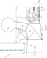
- FIG. 1 a cutaway view of a centrifugal pump 10 according to the present invention is shown.
- a fluid F to be pumped enters the stationary inlet that is formed in a housing or related enclosure 20 and then on to impeller 30 (which acts as a first rotor).
- Diffuser 40 - which is fluidly downstream of impeller 30 - rotates as well (making it act as a second rotor).
- Seals 50 are mounted to secure locations within housing 20 to help contain fluid F and reduce cross-contamination between it and a lubricating fluid (not shown).
- a radially-outward volute 60 acts as a stationary scroll-based collector of the pumped fluid F that is discharged from the impeller 30 and diffuser 40.
- a shaft 70 includes two concentrically-arranged drive shaft portions 70A (for impeller 30 ) and 70B (for the rotating diffuser 40 ) that can rotate relative to one another about bearing 80 that is disposed between the shaft portions 70A and 70B.
- the pump housing 20 may be associated predominantly with the casing formed around the inlet, outlet and fluid F flowpath, as well as defining integral or connectable footers and other structural hardware, it will be understood that additional covers, casing or related containment structure may also be included.
- inlet and outlet flanges form mounting locations to fluidly connect the respective inlet and outlet of pump housing 20 to corresponding conduit (not shown), and may include apertures formed therein to receive screws, bolts or related fasteners that can be used to facilitate such connection.
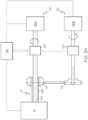
- the rotational movement imparted to the impeller 30 and diffuser 40 through shaft portions 70A and 70B is through the operation of a dual motor 90 ( FIG. 3A ) or a single concentric-shaft motor 100 ( FIG. 3B ), in combination with a variable speed drive transmission 120.
- the movement imparted to the shaft portions 70A and 70B is preferably of a counter-rotational variety, while the motors 90 , 100 are of the alternating current (AC) induction type, where a rotating armature (rotor) is surrounded by a coil-wound stationary field (stator, not shown).
- AC alternating current
- stator windings when electric current (not shown) is passed through the stator windings, a part of the stator known as the pole (which may be made up of a magnetically permeable material, such as iron) around which the windings are wrapped becomes magnetically energized, which in turn imparts an electromagnetic force to the rotor, causing it (as well as the coupled shaft 70 ) to rotate.
- Suitable gearing for example, bevel gears 110
- single motor 100 may comprise concentric rotor configurations 100A, 100B to promote the coupling to the shaft portions 70A and 70B.
- the variable speed drive transmission according to the invention has not been represented in this figure 3B :
- the drive system is configured as two separate motors 90 ( FIG. 3A ) or a single dual-rotor motor 100 ( FIG. 3B ), the rotor's laminated steel plates (not shown) carry magnetic flux that induces electrical current in a squirrel cage or related structure.
- the induced magnetic field in the rotor interacts with the offset magnetic field in the stator, and leads to rotation and the generation of torque.
- wiring is formed as part of the stator and is connected to a voltage source to produce a rotating magnetic field.
- the configuration of the rotor and stator windings may be varied such that the coupled shaft portions 70A , 70B may be independently controlled, including in which direction (i.e., clockwise or counterclockwise) they rotate, thereby providing the desired rotation of the respective impeller 30 and diffuser 40.
- centrifugal pump centrifugal compressor
- the terms “centrifugal pump”, “centrifugal compressor” or the like is meant to include pump or compressor configurations that may also embody some mixed-flow attributes, so long as they chiefly rely upon the movement of the fluid being pumped as it leaves a particular pump stage in a substantially (if not entirely) radial outward direction.
- an impeller with significant mixed-flow attributes is encompassed by the present invention in situations where the diffuser to which it is coupled provides the necessary radially outward flow component.
- the pump 10 design target has a specific speed Ns from about 200 to 6,000 US or English units (where shaft speed is in revolutions per minute (rpm), the flowrate of the pump 10 at its BEP point is in gallons per minute (gpm), and the head is measured in feet).
- Ns is the ability of the pump 10 to avoid cavitation problems associated with low NPSH R values.
- pump 10 may also include multistage variants, and may have single suction or double suction design, as well as overhung or between bearing configurations.
- Preferred uses for pump 10 include chemical processing, oil production (including water injection), oil refining, pipeline (oil, water and other fluids), power plants (fossil, nuclear, combined cycles, cogeneration or the like), water industry, mining industry and biological and pharmaceutical industry applications.
- pump 10 may be configured to accept single- and multi-phase fluids (such as those with air or other gases, as well as solids).
- control system 130 which, based on the design and test data (such as that depicted on curve 200 ) of the pump 10, would have the capability to calculate the best combination of speeds to either achieve best efficiency operation for the operating conditions or best NPSH R performance for suction conditions available.
- the controller 130 may be in the form of a programmable logic controller (PLC) and include digital processing capabilities designed (through appropriate interfaces) to receive input signals and generate output control signals through a central processing unit (CPU).
- PLC programmable logic controller
- CPU central processing unit
- Such a controller 130 may also include a computer-readable medium having stored computer-executable instructions thereon; such medium may also serve as read-only memory (ROM) for storing a program which controls the operation of the overall apparatus and a random-access memory (RAM) having a data storage area.
- the CPU may be connected to an input/output interface.
- such a controller 130 may form part of a larger computer-based control system (not shown) that can be used to communicate and control the operation of various pumps 10 or larger system components.
- the controller 130 may include one or more modules to perform the functionality indicated.
- module refers to an application specific integrated circuit (ASIC), an electronic circuit, a processor (shared, dedicated or group) and memory that executes one or more software or firmware programs, a combinational logic circuit, or other suitable components that provide the desired functionality.
- ASIC application specific integrated circuit
- controller 130 memory may store data corresponding to pump 10 operation (such as curve 200 , as well as an impeller or compressor map or the like) as a lookup table, data structure or other suitable means to allow the controller 130 to determine where the operating state of the pump 10 or motors 90 , 100 is in relation to an optimum condition.
- Such data may be pre-loaded into the controller 130 using information provided by, for example, the pump manufacturer, or built up using a diagnostic routine that varies the operation of the pump 10 and detects certain operational conditions.
- the benefits of using a variable speed mechanism to control the relative speeds of the impeller 30 and diffuser 40 according to the present invention are shown in the form of a graph or curve 200 that depicts a performance metric (in particular, a normalized head or efficiency) versus pump capacity or flow.
- a performance metric in particular, a normalized head or efficiency
- the head and flow characteristic curve 200 of the pump 10 can be made non-dimensional with respect to a reference speed and reference dimensions; in this way, the same curve 200 can be applicable to geometrically similar machines at all speeds.
- These non-dimensional characteristics represent a non-dimensional head or pressure rise along the Y-axis, while the X-axis represents the non-dimensional flow.
- the second part of Y-axis represents the non-dimensional NPSH R of the pump, while points A and B represent the BEP for the first rotor (i.e., impeller 30 ) and second rotor (i.e., diffuser 40 ) if they were a conventional turbo-machine, where the BEP is represented by a maximum of two points on the non-dimensional domain.
- the operation follows the line marked "Locus of BEP Range" between points A and B on the non-dimensional space, and therefore permits great flexibility to adapt to different operating conditions.
- the non-dimensional NPSH R characteristics are also shown to illustrate the flexibility of designing or operating the same pump 10 for a wide range of NPSH conditions.
- impellers similar to impeller 30
- the diffusers similar to diffuser 40
- a pump 10 according to the present invention can be operated such that the diffuser 40 can be made to rotate independently of impeller 30 ; this would broaden the peak of the BEP curve as compared to a conventional pump.
- the diffuser 40 can be operated under a fixed resistance (such as torque imposed by transmission 120 ); thus, it would be stationery until the pressure difference across the vanes of the diffuser 40 exceeds a prescribed limit, after which diffuser 40 starts to rotate.
- a fixed resistance such as torque imposed by transmission 120
- the impeller 30 and diffuser 40 in variable speed counter-rotation relative to one another; the benefit of high head and power density in a single pump is preserved, as well as the ability to allow wide head and flow operating ranges and corresponding NPSH R flexibility.
- the impeller 30 and diffuser 40 may be placed in fixed speed counter-rotation to one another as a way to achieve high pump power density.
- the negative pre-rotation or pre-swirl between the tangential component of the impeller 30 absolute exit velocity and the opposite tangential velocity of diffuser 40 inlet creates an additive term in the Euler's theoretical head value of the diffuser 40. Therefore, the diffuser 40 produces significantly higher head than a single impeller having same exit geometry.
- the total theoretical head of the pump 10 is the Euler's head generated by first rotor (i.e., impeller 30 ) plus the high Euler's head generated by the second rotor (i.e., diffuser 40 ).
- the present inventors modeled pump 10 as a one-dimensional design to include several loss models, deviation or slip function, blade loading, power and efficiency calculations.
- the one-dimensional model demonstrated that the power density coefficient curve has an inflection point and is a function of specific combination of relative rotor speeds.
- the design example parameters were selected based on the highest power density coefficient and efficiency for the desired rated conditions.
- the speeds of the first and second shaft portions 70A and 70B can be independently varied; in one study, the present inventors varied the speed range from slightly below 2000 RPM to slightly above 2000 RPM through two separate electric drives; one of which was a hollow shaft motor such as discussed above.
- the present inventors determined that this arrangement gives significant flexibility in the non-dimensional BEP range of the pump 10, as the BEP is no longer a 'point' in the non-dimensional space but a line (or locus) as a function of relative speed ratio; as discussed above, this is traced out between points A and B in FIG. 2 .
- Some additional extension of flexibility is also possible due to independent variable speed drives.
- optimization of the impeller 30 and diffuser 40 may be achieved using multi-streamline curvature analysis that combines fluid dynamic loss models with a slip or deviation models at the entrance of volute 60.
- the parameters are calculated in a recursive way for each stream line such that the desired pressure profile across the span of the impeller 30 and diffuser 40 is the convergence criterion.
- numerous hypotheses that are sensitive to the most significant and independent parameters may be optimized via fitness-function optimizer tool; in one non-limiting form, scripting may be achieved in Matlab-Reference-Surface-Optimizer (RSO) that is based on a surface approximation (such as with a Kriging model) to search for local minimums with a gradient method.
- RSO Matlab-Reference-Surface-Optimizer
- pump 10 is preferably configured to operate in a low specific speed Ns range (preferably around 6,000), and more particularly in very low specific speed Ns ranges (preferably between about 200 and 1,000 in one form, between about 1,000 and 2,000 in another form, and between about 2,000 and 3,000 in another form).
- a low specific speed Ns range preferably around 6,000
- very low specific speed Ns ranges (preferably between about 200 and 1,000 in one form, between about 1,000 and 2,000 in another form, and between about 2,000 and 3,000 in another form).
- the fitness function of the optimizer tool is based on numerical simulation (CFD) results.
- the fitness function is a weighted function between total head between first rotor inlet and volute inlet and the corresponding efficiency.
- the results, indicated by a maximum efficiency region on the fitness function represent a specific combination of rotors' speeds and the pressure ration between them.
- Optimum geometries were identified and one was chosen for manufacturing and testing in a test rig.
- Transient CFD analysis was also conducted to determine volute losses and incidence losses between first and second rotor and pressure pulsations generated.
- the optimization objective function could be defined in different manner, such as the search for the absolute efficiency maximum or the highest power density or the wider effective working range.
- One significant attribute of the present pump 10 is the wide flexibility over a range of working conditions. Importantly, it allows for the use of a much smaller pump than would otherwise be required, and in some circumstances would - with proper cooperation of controller 130 - relieve the need for a discharge valve (not shown).
- maps may be included as part of the controller 130 memory (for example, as a lookup table) or generated by a suitably-configured algorithm that can be acted upon by the controller 130 CPU, based on input parameters (such as the rotational speeds of the impeller 30 and diffuser 40 ).
- controller 130 may employ feedback-based approaches, such as using sensors (not shown) to observe actual values of impeller-versus-diffuser speed ratios; such knowledge represents an additional degree of freedom for the pump designer.
- feedback-based approaches such as using sensors (not shown) to observe actual values of impeller-versus-diffuser speed ratios; such knowledge represents an additional degree of freedom for the pump designer.
- a set of velocity ratio information may be used to establish pump 10 behavior at the design condition; this information may also be used to improve the performance in off-design conditions.
Description
- The present invention relates generally to pumps, and more particularly to a centrifugal pump with a rotating diffuser.
- Pump impellers and diffusers are well known components that cooperate with one another in rotating turbomachinery to impart energy to a working fluid. In one conventional pump form, the impeller rotates to increase the kinetic energy of the axially-received fluid, while the diffuser (often in the form of an array of vanes) remains stationary and radially outward of the impeller to convert the kinetic energy into pressure energy. Such a pump configuration (typically referred to as a centrifugal pump) is designed to operate best at one set of conditions (called best efficiency point (BEP)) at any given speed.
- Regardless of the configuration, one measure of a pump's capability is referred to generally as the net positive suction head (NPSH), and more particularly as net positive suction head required (NPSHR). Significantly, this is an important indicator of a pump's ability to avoid the destructive effects of cavitation, and running a pump at as low of an NPSHR as possible without running into cavitation problems is desirable in that it avoids the costs and complexities associated with an overdesigned system.
- Conventional forms of centrifugal pumps - with their fixed speed on the impeller, diffuser or both - are able to achieve higher head and power densities, improved NPSHR characteristics or the like while avoiding cavitation, but do so through significant increases in pump complexity and cost, as well as limits in operational range. All of these conditions lead to less than optimum pump operation, as the equilibrium speeds associated with the rotating diffusers are mismatched relative to the needs of the pump for efficient, cavitation-free operation.
- Improvements in NPSHR and related performance may be realized by allowing the diffuser to rotate. In one form, permitting the diffuser to rotate in response to movement in the impeller allows the shear forces inside and outside of the rotating diffuser to establish an equilibrium speed to improve the efficiency of the overall impeller/diffuser stage combination. The shortcoming of such a configuration is that the co-rotational movement of the impeller and diffuser limits the amount of pressure rise that can be produced in the single impeller/diffuser stage. In another form (known as a cascaded, or free spool configuration), the rotating diffuser may be mechanically coupled with a rotating inducer member placed axially and fluidly upstream of the impeller. These configurations tend to have complex bearing arrangements that limit the applicability to low power pump configurations. In yet another form, a geared mechanism can be used to couple both the impeller and diffuser to a fixed speed motor. Such an arrangement limits the increased pressure rise produced by the pump to a discrete range of operating conditions.
EP2466142 A2 andWO 2015/035006 A2 disclose prior art centrifugal pumps with rotating diffusers. - Axial turbomachinery (such as that used in aircraft and marine applications) has employed counter-rotating impellers with no diffuser or collector placed in-between as a way to increase system performance. Nevertheless, such axial flow devices are not suitable for use where mixed flow or radial flow centrifugal pumps are needed, as axial flow machines are configured for low pressure rise (i.e., low head), high flow fluids in gaseous form. As such, the axial-flow turbomachine is not suitable for pumping applications where the pressure rise is such that the specific speed (Ns) - as conventionally defined - only attains very low values. By way of example (using English units), typical axial flow turbomachinery operates in specific speed ranges of between about 7,000 and 20,000, while centrifugal flow and mixed flow turbomachinery ranges are between about 500 and 10,000 and 2,000 and 8,000, respectively. As such, the present inventors are unaware of the use of counter-rotating pump stages below specific speeds of below about 7,000. What is needed is a centrifugal pump with a diffuser that is configured to counter-rotate relative to its companion impeller as a way to improve pump operability in the specific speed ranges typically encountered by such pumps.
- According to the invention, a centrifugal pump according to
claim 1 is provided. - The following detailed description of the present invention can be best understood when read in conjunction with the following drawings, where like structure is indicated with like reference numerals and in which:
-
FIG. 1 is a cutaway view of a pump highlighting the location of various components therein, including rotating impeller and diffuser components according to an embodiment of the present invention; -
FIG. 2 is a graph showing head and NPSH values versus flow characteristics of the pump ofFIG. 1 ; -
FIG. 3A is a simplified cutaway view of the pump ofFIG. 1 being driven by a dual motor-clutch configuration; and -
FIG. 3B is a simplified cutaway view of the pump ofFIG. 1 being driven by a single motor with a concentric hollow shaft. The variable speed transmission of the invention is not represented in this figure. - Referring first to
FIG. 1 , a cutaway view of acentrifugal pump 10 according to the present invention is shown. In it, a fluid F to be pumped enters the stationary inlet that is formed in a housing orrelated enclosure 20 and then on to impeller 30 (which acts as a first rotor). Diffuser 40 - which is fluidly downstream of impeller 30 - rotates as well (making it act as a second rotor).Seals 50 are mounted to secure locations withinhousing 20 to help contain fluid F and reduce cross-contamination between it and a lubricating fluid (not shown). A radially-outwardvolute 60 acts as a stationary scroll-based collector of the pumped fluid F that is discharged from theimpeller 30 anddiffuser 40. Ashaft 70 includes two concentrically-arrangeddrive shaft portions 70A (for impeller 30) and 70B (for the rotating diffuser 40) that can rotate relative to one another about bearing 80 that is disposed between theshaft portions pump housing 20 may be associated predominantly with the casing formed around the inlet, outlet and fluid F flowpath, as well as defining integral or connectable footers and other structural hardware, it will be understood that additional covers, casing or related containment structure may also be included. For example, inlet and outlet flanges form mounting locations to fluidly connect the respective inlet and outlet ofpump housing 20 to corresponding conduit (not shown), and may include apertures formed therein to receive screws, bolts or related fasteners that can be used to facilitate such connection. - Referring next to
FIGS. 3A and3B , the rotational movement imparted to theimpeller 30 and diffuser 40 throughshaft portions FIG. 3A ) or a single concentric-shaft motor 100 (FIG. 3B ), in combination with a variablespeed drive transmission 120. In either case, the movement imparted to theshaft portions motors FIG. 3A as 90A and 90B) to a respective one of theimpeller 30 and diffuser 40, and moreover to permit them to counter-rotate about theshaft 70 axis. Moreover, the rotational speed with which theshaft portions shaft 70 axis may be independently varied throughtransmissions 120. Referring with particularity toFIG. 3B , in another form,single motor 100 may compriseconcentric rotor configurations shaft portions figure 3B : - Regardless the drive system is configured as two separate motors 90 (
FIG. 3A ) or a single dual-rotor motor 100 (FIG. 3B ), the rotor's laminated steel plates (not shown) carry magnetic flux that induces electrical current in a squirrel cage or related structure. The induced magnetic field in the rotor interacts with the offset magnetic field in the stator, and leads to rotation and the generation of torque. Likewise, wiring is formed as part of the stator and is connected to a voltage source to produce a rotating magnetic field. With particular regard to the concentric rotor configuration ofFIG. 3B , the configuration of the rotor and stator windings may be varied such that the coupledshaft portions respective impeller 30 anddiffuser 40. - The present inventors are aware that the nature of the flowpath in axial, mixed-flow and centrifugal machines exists along a continuum, with axial flow occupying one end of the spectrum and centrifugal flow at the opposing end. Within this understanding, in the present context, the terms "centrifugal pump", "centrifugal compressor" or the like is meant to include pump or compressor configurations that may also embody some mixed-flow attributes, so long as they chiefly rely upon the movement of the fluid being pumped as it leaves a particular pump stage in a substantially (if not entirely) radial outward direction. As such, an impeller with significant mixed-flow attributes is encompassed by the present invention in situations where the diffuser to which it is coupled provides the necessary radially outward flow component.
- In a preferred form, the
pump 10 design target has a specific speed Ns from about 200 to 6,000 US or English units (where shaft speed is in revolutions per minute (rpm), the flowrate of thepump 10 at its BEP point is in gallons per minute (gpm), and the head is measured in feet). As is understood by those skilled in the art, one measure of specific speed Ns is the ability of thepump 10 to avoid cavitation problems associated with low NPSHR values. In one form, specific speed Ns is expressed by the following formula:
pump 10 rotational speed n is in revolutions per minute, Q is the flowrate in gpm at the BEP, g is the acceleration due to gravity in feet per second squared and H is the total head at the BEP. - Although shown in single-stage form, pump 10 may also include multistage variants, and may have single suction or double suction design, as well as overhung or between bearing configurations. Preferred uses for
pump 10 include chemical processing, oil production (including water injection), oil refining, pipeline (oil, water and other fluids), power plants (fossil, nuclear, combined cycles, cogeneration or the like), water industry, mining industry and biological and pharmaceutical industry applications. Moreover, pump 10 may be configured to accept single- and multi-phase fluids (such as those with air or other gases, as well as solids). - Referring next to
FIG. 2 in conjunction withFIGS. 3A and3B , a significant part of the invention (especially for its use in variable speed applications) is thecontrol system 130 which, based on the design and test data (such as that depicted on curve 200) of thepump 10, would have the capability to calculate the best combination of speeds to either achieve best efficiency operation for the operating conditions or best NPSHR performance for suction conditions available. In one form, thecontroller 130 may be in the form of a programmable logic controller (PLC) and include digital processing capabilities designed (through appropriate interfaces) to receive input signals and generate output control signals through a central processing unit (CPU). Such acontroller 130 may also include a computer-readable medium having stored computer-executable instructions thereon; such medium may also serve as read-only memory (ROM) for storing a program which controls the operation of the overall apparatus and a random-access memory (RAM) having a data storage area. In one form, the CPU may be connected to an input/output interface. As will be further appreciated, such acontroller 130 may form part of a larger computer-based control system (not shown) that can be used to communicate and control the operation ofvarious pumps 10 or larger system components. Thus, in one form, thecontroller 130 may include one or more modules to perform the functionality indicated. As used herein, the term "module" refers to an application specific integrated circuit (ASIC), an electronic circuit, a processor (shared, dedicated or group) and memory that executes one or more software or firmware programs, a combinational logic circuit, or other suitable components that provide the desired functionality. In one non-limiting example, data corresponding to pump 10 operation (such ascurve 200, as well as an impeller or compressor map or the like) may be stored incontroller 130 memory as a lookup table, data structure or other suitable means to allow thecontroller 130 to determine where the operating state of thepump 10 ormotors controller 130 using information provided by, for example, the pump manufacturer, or built up using a diagnostic routine that varies the operation of thepump 10 and detects certain operational conditions. - The benefits of using a variable speed mechanism to control the relative speeds of the
impeller 30 anddiffuser 40 according to the present invention are shown in the form of a graph orcurve 200 that depicts a performance metric (in particular, a normalized head or efficiency) versus pump capacity or flow. As shown, the head and flowcharacteristic curve 200 of thepump 10 can be made non-dimensional with respect to a reference speed and reference dimensions; in this way, thesame curve 200 can be applicable to geometrically similar machines at all speeds. These non-dimensional characteristics represent a non-dimensional head or pressure rise along the Y-axis, while the X-axis represents the non-dimensional flow. The second part of Y-axis represents the non-dimensional NPSHR of the pump, while points A and B represent the BEP for the first rotor (i.e., impeller 30) and second rotor (i.e., diffuser 40) if they were a conventional turbo-machine, where the BEP is represented by a maximum of two points on the non-dimensional domain. For thepump 10 of the present invention, the operation follows the line marked "Locus of BEP Range" between points A and B on the non-dimensional space, and therefore permits great flexibility to adapt to different operating conditions. The non-dimensional NPSHR characteristics are also shown to illustrate the flexibility of designing or operating thesame pump 10 for a wide range of NPSH conditions. In another embodiment, it is possible to apply the present invention to multistage pumps (not shown); in such a configuration, the impellers (similar to impeller 30) may be mounted on a single shaft (similar to shaft 70) and operated at the same speed while the diffusers (similar to diffuser 40) can be rotated via separate common system in the manner discussed above. - In summary, a
pump 10 according to the present invention can be operated such that thediffuser 40 can be made to rotate independently ofimpeller 30; this would broaden the peak of the BEP curve as compared to a conventional pump. In a more particular scenario, thediffuser 40 can be operated under a fixed resistance (such as torque imposed by transmission 120); thus, it would be stationery until the pressure difference across the vanes of thediffuser 40 exceeds a prescribed limit, after which diffuser 40 starts to rotate. Such a configuration will also limit runaway situations to avoid having the rotatingdiffuser 40 go beyond its mechanical limits. In any event, by placing theimpeller 30 anddiffuser 40 in variable speed counter-rotation relative to one another; the benefit of high head and power density in a single pump is preserved, as well as the ability to allow wide head and flow operating ranges and corresponding NPSHR flexibility. In a variation, theimpeller 30 anddiffuser 40 may be placed in fixed speed counter-rotation to one another as a way to achieve high pump power density. - The negative pre-rotation or pre-swirl between the tangential component of the
impeller 30 absolute exit velocity and the opposite tangential velocity ofdiffuser 40 inlet creates an additive term in the Euler's theoretical head value of thediffuser 40. Therefore, thediffuser 40 produces significantly higher head than a single impeller having same exit geometry. The total theoretical head of thepump 10 is the Euler's head generated by first rotor (i.e., impeller 30) plus the high Euler's head generated by the second rotor (i.e., diffuser 40). - An example of the operation of the present system is described next. In the example, the present inventors modeled
pump 10 as a one-dimensional design to include several loss models, deviation or slip function, blade loading, power and efficiency calculations. The one-dimensional model demonstrated that the power density coefficient curve has an inflection point and is a function of specific combination of relative rotor speeds. The design example parameters were selected based on the highest power density coefficient and efficiency for the desired rated conditions. Unlike conventional geared systems, the speeds of the first andsecond shaft portions impeller 30 and diffuser 40) can be independently varied; in one study, the present inventors varied the speed range from slightly below 2000 RPM to slightly above 2000 RPM through two separate electric drives; one of which was a hollow shaft motor such as discussed above. The present inventors determined that this arrangement gives significant flexibility in the non-dimensional BEP range of thepump 10, as the BEP is no longer a 'point' in the non-dimensional space but a line (or locus) as a function of relative speed ratio; as discussed above, this is traced out between points A and B inFIG. 2 . Some additional extension of flexibility is also possible due to independent variable speed drives. - Optimization of the
impeller 30 anddiffuser 40 may be achieved using multi-streamline curvature analysis that combines fluid dynamic loss models with a slip or deviation models at the entrance ofvolute 60. For example, the parameters are calculated in a recursive way for each stream line such that the desired pressure profile across the span of theimpeller 30 anddiffuser 40 is the convergence criterion. Likewise, numerous hypotheses that are sensitive to the most significant and independent parameters may be optimized via fitness-function optimizer tool; in one non-limiting form, scripting may be achieved in Matlab-Reference-Surface-Optimizer (RSO) that is based on a surface approximation (such as with a Kriging model) to search for local minimums with a gradient method. Such an approach detects optimum specific speed Ns for theimpeller 30 anddiffuser 40; this in turn maximizes the benefits of the present counter-rotating design compared to a machine with the same design point that employs a conventional rotor with fixed trailing stator design. As mentioned above, pump 10 is preferably configured to operate in a low specific speed Ns range (preferably around 6,000), and more particularly in very low specific speed Ns ranges (preferably between about 200 and 1,000 in one form, between about 1,000 and 2,000 in another form, and between about 2,000 and 3,000 in another form). Assuming steady numerical approximation error, the fitness function of the optimizer tool is based on numerical simulation (CFD) results. The fitness function is a weighted function between total head between first rotor inlet and volute inlet and the corresponding efficiency. The results, indicated by a maximum efficiency region on the fitness function represent a specific combination of rotors' speeds and the pressure ration between them. Optimum geometries were identified and one was chosen for manufacturing and testing in a test rig. Transient CFD analysis was also conducted to determine volute losses and incidence losses between first and second rotor and pressure pulsations generated. - The optimization objective function could be defined in different manner, such as the search for the absolute efficiency maximum or the highest power density or the wider effective working range. One significant attribute of the
present pump 10 is the wide flexibility over a range of working conditions. Importantly, it allows for the use of a much smaller pump than would otherwise be required, and in some circumstances would - with proper cooperation of controller 130 - relieve the need for a discharge valve (not shown). As indicated above, maps may be included as part of thecontroller 130 memory (for example, as a lookup table) or generated by a suitably-configured algorithm that can be acted upon by thecontroller 130 CPU, based on input parameters (such as the rotational speeds of theimpeller 30 and diffuser 40). In one form,controller 130 may employ feedback-based approaches, such as using sensors (not shown) to observe actual values of impeller-versus-diffuser speed ratios; such knowledge represents an additional degree of freedom for the pump designer. For example, a set of velocity ratio information may be used to establishpump 10 behavior at the design condition; this information may also be used to improve the performance in off-design conditions. - While certain representative embodiments and details have been shown for purposes of illustrating the invention, it will be apparent to those skilled in the art that various changes may be made without departing from the scope of the invention, which is defined in the appended claims.
Claims (8)
- A centrifugal pump (10) comprising:a housing (20);an impeller (30) rotatably disposed in said housing (20) such that fluid (F) introduced thereto is centrifugally discharged therefrom to experience a first increase in energy;a diffuser (40) rotatably disposed in said housing (20) and placed in fluid communication with said impeller (30) such that upon passage through said diffuser (40), said discharged fluid experiences a second increase in energy;a variable speed drive transmission (120); andat least one motor (90, 100) cooperative with said variable speed drive transmission (120) to impart torque independently to each of said impeller (30) and said diffuser (40);characterised by a controller (130) cooperative with said pump (10), said variable speed drive transmission (120) and said at least one motor (90, 100) to receive data corresponding to operation of said pump (10) and to regulate operation thereof by calculating a combination of speeds to be imparted to said impeller (30) and said diffuser (40) from said variable speed drive transmission (120) based on an operating state of at least one of (a) the pump (10) and (b) the at least one motor (90, 100) in relation to an optimum condition.
- The centrifugal pump (10) of claim 1, wherein wherein the controller (130) cooperates with at least one sensor to define a feedback-based control
- The centrifugal pump of claim 1, wherein said impeller (30) and said diffuser (40) are in counterrotating relationship with one another.
- The centrifugal pump of claim 1, further comprising a concentric shaft (70), wherein said shaft (70) comprises an outer shaft portion (70B) that is rotatably coupled to said diffuser (40) and an inner shaft portion (70A) that is rotatably coupled to said impeller (30).
- The centrifugal pump of claim 1, wherein said at least one motor (90, 100) comprises a single alternating current induction motor (100) that defines a pair of counter-rotating rotors (100A, 100B).
- The centrifugal pump of claim 1, wherein said at least one motor (90, 100) defines a pair of alternating current induction motors (90A, 90B).
- The centrifugal pump of claim 1, wherein said operating state of at least one of (a) the pump (10) and (b) the at least one motor (90, 100) in relation to an optimum condition is selected from the group consisting of best efficiency point and net positive suction head of the pump (10).
- The centrifugal pump of claim 1, wherein the at least one motor (90, 100) comprises a pair of electric drives for independent control of the impeller (30) and diffuser (40), respectively.
Applications Claiming Priority (3)
| Application Number | Priority Date | Filing Date | Title |
|---|---|---|---|
| US201361911269P | 2013-12-03 | 2013-12-03 | |
| PCT/US2014/068306 WO2015084926A1 (en) | 2013-12-03 | 2014-12-03 | Rotating diffuser pump |
| EP14868207.3A EP3077681B1 (en) | 2013-12-03 | 2014-12-03 | Rotating diffuser pump |
Related Parent Applications (1)
| Application Number | Title | Priority Date | Filing Date |
|---|---|---|---|
| EP14868207.3A Division EP3077681B1 (en) | 2013-12-03 | 2014-12-03 | Rotating diffuser pump |
Publications (2)
| Publication Number | Publication Date |
|---|---|
| EP3822490A1 EP3822490A1 (en) | 2021-05-19 |
| EP3822490B1 true EP3822490B1 (en) | 2023-09-13 |
Family
ID=53274059
Family Applications (2)
| Application Number | Title | Priority Date | Filing Date |
|---|---|---|---|
| EP14868207.3A Active EP3077681B1 (en) | 2013-12-03 | 2014-12-03 | Rotating diffuser pump |
| EP20211104.3A Active EP3822490B1 (en) | 2013-12-03 | 2014-12-03 | Rotating diffuser pump |
Family Applications Before (1)
| Application Number | Title | Priority Date | Filing Date |
|---|---|---|---|
| EP14868207.3A Active EP3077681B1 (en) | 2013-12-03 | 2014-12-03 | Rotating diffuser pump |
Country Status (4)
| Country | Link |
|---|---|
| US (1) | US11396887B2 (en) |
| EP (2) | EP3077681B1 (en) |
| ES (2) | ES2856523T3 (en) |
| WO (1) | WO2015084926A1 (en) |
Families Citing this family (21)
| Publication number | Priority date | Publication date | Assignee | Title |
|---|---|---|---|---|
| US20170319085A1 (en) * | 2014-11-14 | 2017-11-09 | Physio-Control, Inc. | Multifunctional healthcare monitoring apparatus |
| DE102016115710B3 (en) * | 2016-08-24 | 2017-10-05 | Institut Für Luft- Und Kältetechnik Gemeinnützige Gmbh | Centrifugal compressor with counter-rotating compressor impellers |
| US11323003B2 (en) * | 2017-10-25 | 2022-05-03 | Flowserve Management Company | Compact, modular, pump or turbine with integral modular motor or generator and coaxial fluid flow |
| US20190120249A1 (en) * | 2017-10-25 | 2019-04-25 | Flowserve Management Company | Modular, multi-stage, integral sealed motor pump with integrally-cooled motors and independently controlled rotor speeds |
| CN107830002B (en) * | 2017-10-27 | 2023-07-04 | 江苏徐工工程机械研究院有限公司 | Electrohydraulic control system and method and aerial work platform |
| US20200056615A1 (en) | 2018-08-16 | 2020-02-20 | Saudi Arabian Oil Company | Motorized pump |
| US20200056462A1 (en) * | 2018-08-16 | 2020-02-20 | Saudi Arabian Oil Company | Motorized pump |
| WO2021026432A1 (en) | 2019-08-07 | 2021-02-11 | Saudi Arabian Oil Company | Determination of geologic permeability correlative with magnetic permeability measured in-situ |
| CN114391066A (en) | 2019-09-18 | 2022-04-22 | 麻省理工学院 | Adaptive volute for centrifugal pump |
| US11371326B2 (en) | 2020-06-01 | 2022-06-28 | Saudi Arabian Oil Company | Downhole pump with switched reluctance motor |
| IT202000017095A1 (en) | 2020-07-14 | 2022-01-14 | Flowserve Man Co | COMPENSATION GROUPS FOR FLUID HANDLING DEVICES AND RELATED DEVICES, SYSTEMS AND METHODS |
| US11499563B2 (en) | 2020-08-24 | 2022-11-15 | Saudi Arabian Oil Company | Self-balancing thrust disk |
| US11920469B2 (en) | 2020-09-08 | 2024-03-05 | Saudi Arabian Oil Company | Determining fluid parameters |
| US11644351B2 (en) | 2021-03-19 | 2023-05-09 | Saudi Arabian Oil Company | Multiphase flow and salinity meter with dual opposite handed helical resonators |
| US11591899B2 (en) | 2021-04-05 | 2023-02-28 | Saudi Arabian Oil Company | Wellbore density meter using a rotor and diffuser |
| US11913464B2 (en) | 2021-04-15 | 2024-02-27 | Saudi Arabian Oil Company | Lubricating an electric submersible pump |
| US11879328B2 (en) | 2021-08-05 | 2024-01-23 | Saudi Arabian Oil Company | Semi-permanent downhole sensor tool |
| US11860077B2 (en) | 2021-12-14 | 2024-01-02 | Saudi Arabian Oil Company | Fluid flow sensor using driver and reference electromechanical resonators |
| EP4296517A1 (en) * | 2022-06-23 | 2023-12-27 | Sulzer Management AG | A pump unit for pumping liquid or suspension and a method for controlling of a pump unit |
| US11867049B1 (en) | 2022-07-19 | 2024-01-09 | Saudi Arabian Oil Company | Downhole logging tool |
| US11913329B1 (en) | 2022-09-21 | 2024-02-27 | Saudi Arabian Oil Company | Untethered logging devices and related methods of logging a wellbore |
Family Cites Families (15)
| Publication number | Priority date | Publication date | Assignee | Title |
|---|---|---|---|---|
| DE564826C (en) * | 1932-11-23 | Siemens Schuckertwerke Akt Ges | Device for conveying gases or liquids with a helical gear in the inlet channel of a centrifugal motor and a diffuser connected between the helical and centrifugal motor and flowed through from the inside to the outside | |
| DE1110810B (en) * | 1956-01-19 | 1961-07-13 | Licentia Gmbh | Counter-rotating compressor or pump |
| GB8507010D0 (en) * | 1985-03-19 | 1985-04-24 | Framo Dev Ltd | Compressor unit |
| JPH01216095A (en) * | 1988-02-24 | 1989-08-30 | Kawanami Shunpei | Double shaft inversion centrifugal type fluid booster |
| CH678352A5 (en) * | 1988-06-23 | 1991-08-30 | Sulzer Ag | |
| GB9127474D0 (en) * | 1991-12-30 | 1992-02-19 | Framo Dev Ltd | Multiphase fluid transport |
| US6433451B1 (en) * | 1995-07-16 | 2002-08-13 | Traian Cherciu | Method and electric motor with rotational stator |
| US6589013B2 (en) | 2001-02-23 | 2003-07-08 | Macro-Micro Devices, Inc. | Fluid flow controller |
| US6776584B2 (en) * | 2002-01-09 | 2004-08-17 | Itt Manufacturing Enterprises, Inc. | Method for determining a centrifugal pump operating state without using traditional measurement sensors |
| US7030528B2 (en) * | 2003-02-06 | 2006-04-18 | General Motors Corporation | Dual concentric AC motor |
| JP5465673B2 (en) * | 2007-10-31 | 2014-04-09 | ジョンソン コントロールズ テクノロジー カンパニー | Control system |
| US9097258B2 (en) * | 2009-06-25 | 2015-08-04 | General Electric Company | Supersonic compressor comprising radial flow path |
| US20120156066A1 (en) * | 2010-12-16 | 2012-06-21 | Eaton Corporation | Concentric multi-stage centrifugal pump with start stage |
| DE102011121925A1 (en) * | 2011-12-22 | 2013-06-27 | Robert Bosch Gmbh | Compressor and method for operating a compressor |
| EP3042083A4 (en) * | 2013-09-05 | 2017-05-10 | Eaton Corporation | Variable output centrifugal pump |
-
2014
- 2014-12-03 EP EP14868207.3A patent/EP3077681B1/en active Active
- 2014-12-03 EP EP20211104.3A patent/EP3822490B1/en active Active
- 2014-12-03 WO PCT/US2014/068306 patent/WO2015084926A1/en active Application Filing
- 2014-12-03 ES ES14868207T patent/ES2856523T3/en active Active
- 2014-12-03 US US15/101,460 patent/US11396887B2/en active Active
- 2014-12-03 ES ES20211104T patent/ES2965756T3/en active Active
Also Published As
| Publication number | Publication date |
|---|---|
| EP3077681B1 (en) | 2020-12-02 |
| EP3077681A4 (en) | 2017-08-16 |
| US11396887B2 (en) | 2022-07-26 |
| US20160305447A1 (en) | 2016-10-20 |
| EP3822490A1 (en) | 2021-05-19 |
| EP3077681A1 (en) | 2016-10-12 |
| WO2015084926A1 (en) | 2015-06-11 |
| ES2965756T3 (en) | 2024-04-16 |
| ES2856523T3 (en) | 2021-09-27 |
Similar Documents
| Publication | Publication Date | Title |
|---|---|---|
| EP3822490B1 (en) | Rotating diffuser pump | |
| Tsukamoto et al. | Transient characteristics of a centrifugal pump during starting period | |
| US10294949B2 (en) | Multistage turbomachine with embedded electric motors | |
| EP2582984B1 (en) | A turbomachine | |
| RU2563406C2 (en) | Turbine plant for energy supply to multi-phase fluid (versions) and method of energy supply to multi-phase fluid | |
| Gravdahl et al. | Modeling of surge in free-spool centrifugal compressors: Experimental validation | |
| JPS6193295A (en) | Fluid machine | |
| Jenny et al. | Experimental determination of mechanical stress induced by rotating stall in unshrouded impellers of centrifugal compressors | |
| Van Esch et al. | Unstable operation of a mixed-flow pump and the influence of tip clearance | |
| US20160230591A1 (en) | Method for operating a turbo-machine having overload protection and turbo-machine comprising a device for carrying out said method | |
| CN105550394B (en) | A kind of modeling method of feed pump | |
| Berten | Hydrodynamics of high specific power pumps for off-design operating conditions | |
| Omri et al. | Numerical study on the transient behavior of a radial pump during starting time | |
| Araste et al. | Study of-electromechanical coupling in a motor-driven centrifugal pump for fault detection and diagnosis | |
| Kita et al. | Prediction of subsynchronous rotor vibration amplitude caused by rotating stall | |
| Li et al. | Blade interaction forces in a mixed-flow pump with vaned diffuser | |
| Borovkov et al. | Design and features of the ECC-55 experimental rig for gas-dynamic tests of model centrifugal compressor stages | |
| Mejri et al. | Influence of peripheral blade angle on performance and stability of axial inducers | |
| Höller et al. | Investigation of the 4-Quadrant behaviour of a mixed flow diffuser pump with CFD-methods and test rig evaluation | |
| Araste et al. | Multi-domain modeling platform for electrical-signature-based condition monitoring of motor-driven pumps | |
| Miura et al. | Numerical and Experimental Study on Rotating Stall in Industrial Centrifugal Compressor | |
| Oh et al. | Development of high-speed industrial turbo blowers with foil air bearings | |
| Rutter et al. | Numerical Simulation and Design Optimization of an Electrical Submersible Power Recovery Turbine | |
| Tosin et al. | Experimental and numerical investigation of a counter-rotating mixed-flow single stage pump | |
| RU2691706C2 (en) | Operating method of multistage axial machines |
Legal Events
| Date | Code | Title | Description |
|---|---|---|---|
| PUAI | Public reference made under article 153(3) epc to a published international application that has entered the european phase |
Free format text: ORIGINAL CODE: 0009012 |
|
| STAA | Information on the status of an ep patent application or granted ep patent |
Free format text: STATUS: THE APPLICATION HAS BEEN PUBLISHED |
|
| AC | Divisional application: reference to earlier application |
Ref document number: 3077681 Country of ref document: EP Kind code of ref document: P |
|
| AK | Designated contracting states |
Kind code of ref document: A1 Designated state(s): AL AT BE BG CH CY CZ DE DK EE ES FI FR GB GR HR HU IE IS IT LI LT LU LV MC MK MT NL NO PL PT RO RS SE SI SK SM TR |
|
| STAA | Information on the status of an ep patent application or granted ep patent |
Free format text: STATUS: REQUEST FOR EXAMINATION WAS MADE |
|
| 17P | Request for examination filed |
Effective date: 20211119 |
|
| RBV | Designated contracting states (corrected) |
Designated state(s): AL AT BE BG CH CY CZ DE DK EE ES FI FR GB GR HR HU IE IS IT LI LT LU LV MC MK MT NL NO PL PT RO RS SE SI SK SM TR |
|
| GRAP | Despatch of communication of intention to grant a patent |
Free format text: ORIGINAL CODE: EPIDOSNIGR1 |
|
| STAA | Information on the status of an ep patent application or granted ep patent |
Free format text: STATUS: GRANT OF PATENT IS INTENDED |
|
| RIC1 | Information provided on ipc code assigned before grant |
Ipc: F04D 13/06 20060101ALN20230302BHEP Ipc: H02K 16/02 20060101ALI20230302BHEP Ipc: H02K 7/14 20060101ALI20230302BHEP Ipc: F04D 1/00 20060101ALI20230302BHEP Ipc: F04D 29/44 20060101AFI20230302BHEP |
|
| INTG | Intention to grant announced |
Effective date: 20230330 |
|
| RIC1 | Information provided on ipc code assigned before grant |
Ipc: F04D 13/06 20060101ALN20230320BHEP Ipc: H02K 16/02 20060101ALI20230320BHEP Ipc: H02K 7/14 20060101ALI20230320BHEP Ipc: F04D 1/00 20060101ALI20230320BHEP Ipc: F04D 29/44 20060101AFI20230320BHEP |
|
| P01 | Opt-out of the competence of the unified patent court (upc) registered |
Effective date: 20230526 |
|
| GRAS | Grant fee paid |
Free format text: ORIGINAL CODE: EPIDOSNIGR3 |
|
| GRAA | (expected) grant |
Free format text: ORIGINAL CODE: 0009210 |
|
| STAA | Information on the status of an ep patent application or granted ep patent |
Free format text: STATUS: THE PATENT HAS BEEN GRANTED |
|
| AC | Divisional application: reference to earlier application |
Ref document number: 3077681 Country of ref document: EP Kind code of ref document: P |
|
| AK | Designated contracting states |
Kind code of ref document: B1 Designated state(s): AL AT BE BG CH CY CZ DE DK EE ES FI FR GB GR HR HU IE IS IT LI LT LU LV MC MK MT NL NO PL PT RO RS SE SI SK SM TR |
|
| REG | Reference to a national code |
Ref country code: CH Ref legal event code: EP |
|
| REG | Reference to a national code |
Ref country code: DE Ref legal event code: R096 Ref document number: 602014088345 Country of ref document: DE |
|
| REG | Reference to a national code |
Ref country code: IE Ref legal event code: FG4D |
|
| REG | Reference to a national code |
Ref country code: NL Ref legal event code: FP |
|
| REG | Reference to a national code |
Ref country code: LT Ref legal event code: MG9D |
|
| PG25 | Lapsed in a contracting state [announced via postgrant information from national office to epo] |
Ref country code: GR Free format text: LAPSE BECAUSE OF FAILURE TO SUBMIT A TRANSLATION OF THE DESCRIPTION OR TO PAY THE FEE WITHIN THE PRESCRIBED TIME-LIMIT Effective date: 20231214 |
|
| PG25 | Lapsed in a contracting state [announced via postgrant information from national office to epo] |
Ref country code: SE Free format text: LAPSE BECAUSE OF FAILURE TO SUBMIT A TRANSLATION OF THE DESCRIPTION OR TO PAY THE FEE WITHIN THE PRESCRIBED TIME-LIMIT Effective date: 20230913 Ref country code: RS Free format text: LAPSE BECAUSE OF FAILURE TO SUBMIT A TRANSLATION OF THE DESCRIPTION OR TO PAY THE FEE WITHIN THE PRESCRIBED TIME-LIMIT Effective date: 20230913 Ref country code: NO Free format text: LAPSE BECAUSE OF FAILURE TO SUBMIT A TRANSLATION OF THE DESCRIPTION OR TO PAY THE FEE WITHIN THE PRESCRIBED TIME-LIMIT Effective date: 20231213 Ref country code: LV Free format text: LAPSE BECAUSE OF FAILURE TO SUBMIT A TRANSLATION OF THE DESCRIPTION OR TO PAY THE FEE WITHIN THE PRESCRIBED TIME-LIMIT Effective date: 20230913 Ref country code: LT Free format text: LAPSE BECAUSE OF FAILURE TO SUBMIT A TRANSLATION OF THE DESCRIPTION OR TO PAY THE FEE WITHIN THE PRESCRIBED TIME-LIMIT Effective date: 20230913 Ref country code: HR Free format text: LAPSE BECAUSE OF FAILURE TO SUBMIT A TRANSLATION OF THE DESCRIPTION OR TO PAY THE FEE WITHIN THE PRESCRIBED TIME-LIMIT Effective date: 20230913 Ref country code: GR Free format text: LAPSE BECAUSE OF FAILURE TO SUBMIT A TRANSLATION OF THE DESCRIPTION OR TO PAY THE FEE WITHIN THE PRESCRIBED TIME-LIMIT Effective date: 20231214 Ref country code: FI Free format text: LAPSE BECAUSE OF FAILURE TO SUBMIT A TRANSLATION OF THE DESCRIPTION OR TO PAY THE FEE WITHIN THE PRESCRIBED TIME-LIMIT Effective date: 20230913 |
|
| REG | Reference to a national code |
Ref country code: AT Ref legal event code: MK05 Ref document number: 1611561 Country of ref document: AT Kind code of ref document: T Effective date: 20230913 |
|
| PG25 | Lapsed in a contracting state [announced via postgrant information from national office to epo] |
Ref country code: IS Free format text: LAPSE BECAUSE OF FAILURE TO SUBMIT A TRANSLATION OF THE DESCRIPTION OR TO PAY THE FEE WITHIN THE PRESCRIBED TIME-LIMIT Effective date: 20240113 |
|
| REG | Reference to a national code |
Ref country code: ES Ref legal event code: FG2A Ref document number: 2965756 Country of ref document: ES Kind code of ref document: T3 Effective date: 20240416 |