EP3822390A1 - Apparatus for depositing atomic layer - Google Patents
Apparatus for depositing atomic layer Download PDFInfo
- Publication number
- EP3822390A1 EP3822390A1 EP19861362.2A EP19861362A EP3822390A1 EP 3822390 A1 EP3822390 A1 EP 3822390A1 EP 19861362 A EP19861362 A EP 19861362A EP 3822390 A1 EP3822390 A1 EP 3822390A1
- Authority
- EP
- European Patent Office
- Prior art keywords
- precursor
- substrate
- gas
- supply
- atomic layer
- Prior art date
- Legal status (The legal status is an assumption and is not a legal conclusion. Google has not performed a legal analysis and makes no representation as to the accuracy of the status listed.)
- Pending
Links
Images

Classifications
-
- C—CHEMISTRY; METALLURGY
- C23—COATING METALLIC MATERIAL; COATING MATERIAL WITH METALLIC MATERIAL; CHEMICAL SURFACE TREATMENT; DIFFUSION TREATMENT OF METALLIC MATERIAL; COATING BY VACUUM EVAPORATION, BY SPUTTERING, BY ION IMPLANTATION OR BY CHEMICAL VAPOUR DEPOSITION, IN GENERAL; INHIBITING CORROSION OF METALLIC MATERIAL OR INCRUSTATION IN GENERAL
- C23C—COATING METALLIC MATERIAL; COATING MATERIAL WITH METALLIC MATERIAL; SURFACE TREATMENT OF METALLIC MATERIAL BY DIFFUSION INTO THE SURFACE, BY CHEMICAL CONVERSION OR SUBSTITUTION; COATING BY VACUUM EVAPORATION, BY SPUTTERING, BY ION IMPLANTATION OR BY CHEMICAL VAPOUR DEPOSITION, IN GENERAL
- C23C16/00—Chemical coating by decomposition of gaseous compounds, without leaving reaction products of surface material in the coating, i.e. chemical vapour deposition [CVD] processes
- C23C16/44—Chemical coating by decomposition of gaseous compounds, without leaving reaction products of surface material in the coating, i.e. chemical vapour deposition [CVD] processes characterised by the method of coating
- C23C16/455—Chemical coating by decomposition of gaseous compounds, without leaving reaction products of surface material in the coating, i.e. chemical vapour deposition [CVD] processes characterised by the method of coating characterised by the method used for introducing gases into reaction chamber or for modifying gas flows in reaction chamber
- C23C16/45523—Pulsed gas flow or change of composition over time
- C23C16/45525—Atomic layer deposition [ALD]
- C23C16/45544—Atomic layer deposition [ALD] characterized by the apparatus
- C23C16/45548—Atomic layer deposition [ALD] characterized by the apparatus having arrangements for gas injection at different locations of the reactor for each ALD half-reaction
- C23C16/45551—Atomic layer deposition [ALD] characterized by the apparatus having arrangements for gas injection at different locations of the reactor for each ALD half-reaction for relative movement of the substrate and the gas injectors or half-reaction reactor compartments
-
- C—CHEMISTRY; METALLURGY
- C23—COATING METALLIC MATERIAL; COATING MATERIAL WITH METALLIC MATERIAL; CHEMICAL SURFACE TREATMENT; DIFFUSION TREATMENT OF METALLIC MATERIAL; COATING BY VACUUM EVAPORATION, BY SPUTTERING, BY ION IMPLANTATION OR BY CHEMICAL VAPOUR DEPOSITION, IN GENERAL; INHIBITING CORROSION OF METALLIC MATERIAL OR INCRUSTATION IN GENERAL
- C23C—COATING METALLIC MATERIAL; COATING MATERIAL WITH METALLIC MATERIAL; SURFACE TREATMENT OF METALLIC MATERIAL BY DIFFUSION INTO THE SURFACE, BY CHEMICAL CONVERSION OR SUBSTITUTION; COATING BY VACUUM EVAPORATION, BY SPUTTERING, BY ION IMPLANTATION OR BY CHEMICAL VAPOUR DEPOSITION, IN GENERAL
- C23C16/00—Chemical coating by decomposition of gaseous compounds, without leaving reaction products of surface material in the coating, i.e. chemical vapour deposition [CVD] processes
- C23C16/04—Coating on selected surface areas, e.g. using masks
-
- C—CHEMISTRY; METALLURGY
- C23—COATING METALLIC MATERIAL; COATING MATERIAL WITH METALLIC MATERIAL; CHEMICAL SURFACE TREATMENT; DIFFUSION TREATMENT OF METALLIC MATERIAL; COATING BY VACUUM EVAPORATION, BY SPUTTERING, BY ION IMPLANTATION OR BY CHEMICAL VAPOUR DEPOSITION, IN GENERAL; INHIBITING CORROSION OF METALLIC MATERIAL OR INCRUSTATION IN GENERAL
- C23C—COATING METALLIC MATERIAL; COATING MATERIAL WITH METALLIC MATERIAL; SURFACE TREATMENT OF METALLIC MATERIAL BY DIFFUSION INTO THE SURFACE, BY CHEMICAL CONVERSION OR SUBSTITUTION; COATING BY VACUUM EVAPORATION, BY SPUTTERING, BY ION IMPLANTATION OR BY CHEMICAL VAPOUR DEPOSITION, IN GENERAL
- C23C16/00—Chemical coating by decomposition of gaseous compounds, without leaving reaction products of surface material in the coating, i.e. chemical vapour deposition [CVD] processes
- C23C16/44—Chemical coating by decomposition of gaseous compounds, without leaving reaction products of surface material in the coating, i.e. chemical vapour deposition [CVD] processes characterised by the method of coating
- C23C16/455—Chemical coating by decomposition of gaseous compounds, without leaving reaction products of surface material in the coating, i.e. chemical vapour deposition [CVD] processes characterised by the method of coating characterised by the method used for introducing gases into reaction chamber or for modifying gas flows in reaction chamber
-
- C—CHEMISTRY; METALLURGY
- C23—COATING METALLIC MATERIAL; COATING MATERIAL WITH METALLIC MATERIAL; CHEMICAL SURFACE TREATMENT; DIFFUSION TREATMENT OF METALLIC MATERIAL; COATING BY VACUUM EVAPORATION, BY SPUTTERING, BY ION IMPLANTATION OR BY CHEMICAL VAPOUR DEPOSITION, IN GENERAL; INHIBITING CORROSION OF METALLIC MATERIAL OR INCRUSTATION IN GENERAL
- C23C—COATING METALLIC MATERIAL; COATING MATERIAL WITH METALLIC MATERIAL; SURFACE TREATMENT OF METALLIC MATERIAL BY DIFFUSION INTO THE SURFACE, BY CHEMICAL CONVERSION OR SUBSTITUTION; COATING BY VACUUM EVAPORATION, BY SPUTTERING, BY ION IMPLANTATION OR BY CHEMICAL VAPOUR DEPOSITION, IN GENERAL
- C23C16/00—Chemical coating by decomposition of gaseous compounds, without leaving reaction products of surface material in the coating, i.e. chemical vapour deposition [CVD] processes
- C23C16/44—Chemical coating by decomposition of gaseous compounds, without leaving reaction products of surface material in the coating, i.e. chemical vapour deposition [CVD] processes characterised by the method of coating
- C23C16/455—Chemical coating by decomposition of gaseous compounds, without leaving reaction products of surface material in the coating, i.e. chemical vapour deposition [CVD] processes characterised by the method of coating characterised by the method used for introducing gases into reaction chamber or for modifying gas flows in reaction chamber
- C23C16/45519—Inert gas curtains
-
- C—CHEMISTRY; METALLURGY
- C23—COATING METALLIC MATERIAL; COATING MATERIAL WITH METALLIC MATERIAL; CHEMICAL SURFACE TREATMENT; DIFFUSION TREATMENT OF METALLIC MATERIAL; COATING BY VACUUM EVAPORATION, BY SPUTTERING, BY ION IMPLANTATION OR BY CHEMICAL VAPOUR DEPOSITION, IN GENERAL; INHIBITING CORROSION OF METALLIC MATERIAL OR INCRUSTATION IN GENERAL
- C23C—COATING METALLIC MATERIAL; COATING MATERIAL WITH METALLIC MATERIAL; SURFACE TREATMENT OF METALLIC MATERIAL BY DIFFUSION INTO THE SURFACE, BY CHEMICAL CONVERSION OR SUBSTITUTION; COATING BY VACUUM EVAPORATION, BY SPUTTERING, BY ION IMPLANTATION OR BY CHEMICAL VAPOUR DEPOSITION, IN GENERAL
- C23C16/00—Chemical coating by decomposition of gaseous compounds, without leaving reaction products of surface material in the coating, i.e. chemical vapour deposition [CVD] processes
- C23C16/44—Chemical coating by decomposition of gaseous compounds, without leaving reaction products of surface material in the coating, i.e. chemical vapour deposition [CVD] processes characterised by the method of coating
- C23C16/455—Chemical coating by decomposition of gaseous compounds, without leaving reaction products of surface material in the coating, i.e. chemical vapour deposition [CVD] processes characterised by the method of coating characterised by the method used for introducing gases into reaction chamber or for modifying gas flows in reaction chamber
- C23C16/45563—Gas nozzles
-
- C—CHEMISTRY; METALLURGY
- C23—COATING METALLIC MATERIAL; COATING MATERIAL WITH METALLIC MATERIAL; CHEMICAL SURFACE TREATMENT; DIFFUSION TREATMENT OF METALLIC MATERIAL; COATING BY VACUUM EVAPORATION, BY SPUTTERING, BY ION IMPLANTATION OR BY CHEMICAL VAPOUR DEPOSITION, IN GENERAL; INHIBITING CORROSION OF METALLIC MATERIAL OR INCRUSTATION IN GENERAL
- C23C—COATING METALLIC MATERIAL; COATING MATERIAL WITH METALLIC MATERIAL; SURFACE TREATMENT OF METALLIC MATERIAL BY DIFFUSION INTO THE SURFACE, BY CHEMICAL CONVERSION OR SUBSTITUTION; COATING BY VACUUM EVAPORATION, BY SPUTTERING, BY ION IMPLANTATION OR BY CHEMICAL VAPOUR DEPOSITION, IN GENERAL
- C23C16/00—Chemical coating by decomposition of gaseous compounds, without leaving reaction products of surface material in the coating, i.e. chemical vapour deposition [CVD] processes
- C23C16/44—Chemical coating by decomposition of gaseous compounds, without leaving reaction products of surface material in the coating, i.e. chemical vapour deposition [CVD] processes characterised by the method of coating
- C23C16/455—Chemical coating by decomposition of gaseous compounds, without leaving reaction products of surface material in the coating, i.e. chemical vapour deposition [CVD] processes characterised by the method of coating characterised by the method used for introducing gases into reaction chamber or for modifying gas flows in reaction chamber
- C23C16/45563—Gas nozzles
- C23C16/45574—Nozzles for more than one gas
-
- C—CHEMISTRY; METALLURGY
- C23—COATING METALLIC MATERIAL; COATING MATERIAL WITH METALLIC MATERIAL; CHEMICAL SURFACE TREATMENT; DIFFUSION TREATMENT OF METALLIC MATERIAL; COATING BY VACUUM EVAPORATION, BY SPUTTERING, BY ION IMPLANTATION OR BY CHEMICAL VAPOUR DEPOSITION, IN GENERAL; INHIBITING CORROSION OF METALLIC MATERIAL OR INCRUSTATION IN GENERAL
- C23C—COATING METALLIC MATERIAL; COATING MATERIAL WITH METALLIC MATERIAL; SURFACE TREATMENT OF METALLIC MATERIAL BY DIFFUSION INTO THE SURFACE, BY CHEMICAL CONVERSION OR SUBSTITUTION; COATING BY VACUUM EVAPORATION, BY SPUTTERING, BY ION IMPLANTATION OR BY CHEMICAL VAPOUR DEPOSITION, IN GENERAL
- C23C16/00—Chemical coating by decomposition of gaseous compounds, without leaving reaction products of surface material in the coating, i.e. chemical vapour deposition [CVD] processes
- C23C16/44—Chemical coating by decomposition of gaseous compounds, without leaving reaction products of surface material in the coating, i.e. chemical vapour deposition [CVD] processes characterised by the method of coating
- C23C16/54—Apparatus specially adapted for continuous coating
-
- C—CHEMISTRY; METALLURGY
- C23—COATING METALLIC MATERIAL; COATING MATERIAL WITH METALLIC MATERIAL; CHEMICAL SURFACE TREATMENT; DIFFUSION TREATMENT OF METALLIC MATERIAL; COATING BY VACUUM EVAPORATION, BY SPUTTERING, BY ION IMPLANTATION OR BY CHEMICAL VAPOUR DEPOSITION, IN GENERAL; INHIBITING CORROSION OF METALLIC MATERIAL OR INCRUSTATION IN GENERAL
- C23C—COATING METALLIC MATERIAL; COATING MATERIAL WITH METALLIC MATERIAL; SURFACE TREATMENT OF METALLIC MATERIAL BY DIFFUSION INTO THE SURFACE, BY CHEMICAL CONVERSION OR SUBSTITUTION; COATING BY VACUUM EVAPORATION, BY SPUTTERING, BY ION IMPLANTATION OR BY CHEMICAL VAPOUR DEPOSITION, IN GENERAL
- C23C16/00—Chemical coating by decomposition of gaseous compounds, without leaving reaction products of surface material in the coating, i.e. chemical vapour deposition [CVD] processes
- C23C16/44—Chemical coating by decomposition of gaseous compounds, without leaving reaction products of surface material in the coating, i.e. chemical vapour deposition [CVD] processes characterised by the method of coating
- C23C16/54—Apparatus specially adapted for continuous coating
- C23C16/545—Apparatus specially adapted for continuous coating for coating elongated substrates
Definitions
- the present invention relates to an atomic layer deposition apparatus.
- a method of forming a film on a substrate there is, for example, an atomic layer deposition method.
- the atomic layer deposition is typically a technique for forming a film on a substrate based on sequential supply of gas phase chemicals, which has been applied to various fields.
- the supply type of a precursor gas and a purge gas may be divided into a nozzle method and a region division method.
- the nozzle method is a type in which the precursor gas and the purge gas are supplied through nozzles which are regularly repeated and arranged in a space.
- Figure 1 is a schematic view showing a nozzle type atomic layer deposition apparatus (1).
- the atomic layer deposition apparatus (1) comprises a nozzle (10) having a plurality of supply ports (11, 12, 13) and a transfer device for transferring a substrate (20).
- the nozzle (10) has precursor gas supply ports (11, 12) for supplying one or more precursor gases (precursor A, B) and purge gas supply ports (13) for supplying a purge gas such as an inert gas.
- the nozzle method has a small gas consumption, there is a disadvantage that the gas exposure time is insufficient when the traveling speed of the substrate is increased.
- the region division method is a method of dividing the atomic layer deposition apparatus into a precursor gas space and a purge gas space, and then filling each entire space with the precursor gas and the purge gas.
- the region division method can secure a sufficient gas exposure time according to the region width, but has a disadvantage of a large gas consumption.
- an atomic layer deposition apparatus which comprises a first precursor supply region where a first gas supply nozzle having a plurality of first precursor gas supply ports arranged in sequence along the traveling direction of a substrate so as to supply a first precursor gas on the substrate when the substrate travels, is disposed, a second precursor supply region provided so as to supply a second precursor gas on the substrate when the substrate travels, a purge gas supply region positioned between the first precursor supply region and the second precursor supply region, opened to each of the first precursor supply region and the second precursor supply region, and provided so as to supply a purge gas on the substrate when the substrate travels; and a roll unit provided with a plurality of guide rolls arranged such that the substrate passes through the purge gas supply region each time to traverse multiple times between the first precursor supply region and the second precursor supply region.
- the atomic layer deposition apparatus related to at least one example of the present invention has the following effects.
- Figure 2 is a schematic view showing an atomic layer deposition apparatus (100) related to one example of the present invention
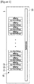
- Figure 3 is a plan view of a first gas supply nozzle
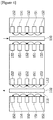
- Figure 4 is a schematic view showing a pair of gas supply nozzles
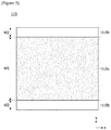
- Figure 5 is a plan view of a substrate.
- the atomic layer deposition apparatus (100) comprises a first precursor supply region (101), a second precursor supply region (102) and a purge gas supply region (103).
- the atomic layer deposition apparatus (100) related to one example of the present invention is a roll-to-roll atomic layer deposition apparatus (100). Particularly, it is an atomic layer deposition apparatus (100) that the first precursor supply region (101), the purge gas supply region (103) and the second precursor supply region (102) are divided. Specifically, the precursor supply method of at least one of the first precursor and the second precursor may be implemented by the nozzle method, and the purge gas supply method may be implemented in a state where the purge gas is filled in the purge gas supply region, as in a conventional space division atomic layer deposition apparatus.
- Each of the supply regions (101, 102, 103) provides a treatment region where the precursor gas is deposited on the substrate (300) to form a film or the purge gas is supplied.
- each of the supply regions (101, 102, 103) is provided such that the process temperature and process pressure may be adjusted.
- one of the first precursor and the second precursor may be TMA (trimethyl-aluminum), and the other may be H 2 O.
- the substrate (110) is an electrode substrate, which may be, particularly, a positive electrode or a negative electrode of a lithium ion secondary battery for automobiles, and the substrate (110) may have a first surface (111) and a second surface (112) opposite to the first surface (111), wherein an electrode layer may be formed on each of the first surface (111) and the second surface (112).
- the substrate (110) may be a substrate formed of a flexible material so that it can also cope with a direction change section as well as a straight section when traveling along the guide roll.
- the atomic layer deposition apparatus (100) of the present invention may have a structure capable of simultaneous deposition on both sides so as to form a film on each electrode layer of the first surface (111) and the second surface (112) of the substrate (110).
- the atomic layer deposition apparatus (100) comprises the first precursor supply region (101) where first supply nozzles (150) provided such that the first precursor gas is supplied on the substrate (110) when the substrate (110) travels, are disposed.
- first gas supply nozzles (150) are disposed in the first precursor supply region (101) so that the first precursor is supplied by the nozzle method.
- the first gas supply nozzles (150) may be disposed in a linear travel section of the substrate (110) in the first precursor supply region.
- a plurality of first gas supply nozzles (150) may be disposed in the first precursor supply region (101) along the traveling direction of the substrate.
- a pair of first gas supply nozzles (150) provided such that the first precursor gas is supplied toward each of the first surface (111) of the substrate (110) and the second surface (112) opposite to the first surface (111) may be disposed in the first precursor supply region (101).
- first gas supply nozzles (150) may be provided such that the interval from the substrate is adjustable.
- the atomic layer deposition apparatus (100) comprises the second precursor supply region (103) provided such that the second precursor gas is supplied on the substrate (110) when the substrate (110) travels.
- the second precursor supply region (102) may be provided such that the corresponding region is filled with the second precursor gas, as in the conventional space division method.
- second gas supply nozzles (160) provided such that the second precursor gas is supplied on the substrate (110) may be disposed in the second precursor supply region (102).
- the second gas supply nozzles (160) may be disposed in a linear travel section of the substrate (110) in the second precursor supply region.
- a plurality of second gas supply nozzles (160) may be disposed in the second precursor supply region (102) along the traveling direction of the substrate.
- a pair of second gas supply nozzles (160) provided such that the second precursor gas is supplied toward each of the first surface (111) of the substrate (110) and the second surface (112) opposite to the first surface (111) may be disposed in the second precursor supply region (102).
- the atomic layer deposition apparatus (100) comprises the purge gas supply region (103) positioned between the first precursor supply region (101) and the second precursor supply region (102), opened to each of the first precursor supply region (101) and the second precursor supply region (102), and provided so as to supply a purge gas on the substrate when the substrate (110) travels.
- the purge gas supply region (103) is provided with a plurality of slits (104), through which the substrate (110) can pass, so as to be opened to each of the first precursor supply region (101) and the second precursor supply region (102).
- the atomic layer deposition apparatus (100) comprises the roll unit (130) provided with a plurality of guide rolls (131, 132) arranged such that the substrate passes through the purge gas supply region (103) each time to traverse multiple times between the first precursor supply region (101) and the second precursor supply region (102).
- the guide roll arranged in the first precursor supply region (101) is referred to as a first guide roll (131), and the guide roll arranged in the second precursor supply region (102) is referred to as a second guide roll (132).
- the substrate (110) travels through the first precursor supply region (101), the purge gas supply region (130) and the second precursor supply region (102), and then travels through the purge gas supply region (130) and the first precursor supply region (101).
- the x-axis direction represents the traveling direction of the substrate (110), and the y-axis direction represents the width direction of the substrate (110).
- the first gas supply nozzle (150) may have a plurality of first precursor gas supply ports (154, for example, H 2 O supply ports) arranged in sequence along the traveling direction of the substrate (110) and first and second gas curtain ports (155) located on both sides based on the traveling direction of the substrate (only the first gas curtain port is shown on the left side in Figure 3 ).
- the first precursor gas supply port (154) comprises a plurality of first precursor gas supply holes (151) arranged along the width direction of the substrate.
- the first and second gas curtain ports perform a function of forming boundaries of the gas supply regions such that the first precursor gas non-deposited regions (110b) are each generated along the traveling direction on both sides based on the traveling direction of the substrate (110).
- Each gas curtain port may have a plurality of gas injection holes (153).
- the gas injection holes (153) may be arranged along the traveling direction of the substrate, where an inert gas (for example, N2) may be injected through the gas injection holes (153).
- vacuum ports (152) are provided between two adjacent first precursor gas supply ports (154).
- the first precursor gas supply ports (154) are connected to a corresponding precursor gas supply source and provided so as to inject the first precursor gas toward the substrate (110), whereby a film is formed on the substrate (110).
- a 'gas supply region the region where the first precursor gas is applied on the substrate (110) through the first precursor gas supply ports (154) may be referred herein to as a 'gas supply region.
- each gas curtain port (155) is connected to a supply source of an inert gas (for example, N 2 ), where the inert gas is injected toward the substrate (110) through the gas curtain ports (155).
- each gas curtain port (155) may have a channel shape extending along the traveling direction of the substrate.
- each gas curtain port (155) may be arranged in an orthogonal state with the precursor gas supply port (154).
- the first and second gas curtain ports (155) form boundaries of the gas supply regions such that the precursor gas non-deposited regions (110b) are each generated along the traveling direction on both sides (both edges in the width direction) based on the traveling direction of the substrate (110). That is, the first and second gas curtain ports (155) are provided so as to inject the inert gas to both edges in the width direction of the substrate (110).
- the inert gas is injected through the first and second gas curtain ports (155).
- the precursor gas injected onto the substrate (110) through the first precursor gas supply port (154) is not applied to both edges in the width direction of the substrate (110) by the inert gas injected from the first and second gas curtain ports (155). Accordingly, the substrate (110) is divided into the deposited region (110a) in the central portion and the non-deposited region (110b) at both edges in the width direction (see Figure 5 ).
- first and second gas curtain ports (155) may be provided so as to form boundaries of the gas supply regions with respect to the plurality of first precursor gas supply ports (154).
- first and second gas curtain ports (155) may also be provided so as to form boundaries of the gas supply regions with respect to some of the plurality of first precursor gas supply ports (154).
- the non-deposited region (110b) of the substrate (110) may have a width (w2) of 0.5mm to 20mm.
- the traveling speed of the substrate may be 0.5 to 50m/min, and for example, the deposition speed at a traveling speed of 12m/min may be 5.3nm/min.
- the second gas supply nozzle (160) has the same structure as that of the first gas supply nozzle. Briefly, it has a plurality of second precursor gas supply ports arranged in sequence along the traveling direction of the substrate and first and second gas curtain ports located on both sides based on the traveling direction of the substrate.
- first and second gas curtain ports form boundaries of the gas supply regions such that the second precursor gas non-deposited regions are each generated along the traveling direction on both sides based on the traveling direction of the substrate.
- vacuum ports are provided between two adjacent precursor gas supply ports.
- the atomic layer deposition apparatus related to at least one example of the present invention can reduce a gas consumption while sufficiently securing a gas exposure time upon traveling a substrate through a roll-to-roll process.
Landscapes
- Chemical & Material Sciences (AREA)
- General Chemical & Material Sciences (AREA)
- Chemical Kinetics & Catalysis (AREA)
- Engineering & Computer Science (AREA)
- Materials Engineering (AREA)
- Mechanical Engineering (AREA)
- Metallurgy (AREA)
- Organic Chemistry (AREA)
- Chemical Vapour Deposition (AREA)
Abstract
Description
- The present invention relates to an atomic layer deposition apparatus.
- This application claims the benefit of priority based on Korean Patent Application No.
10-2018-0112849 filed on September 20, 2018 - As a method of forming a film on a substrate, there is, for example, an atomic layer deposition method.
- The atomic layer deposition (ALD) is typically a technique for forming a film on a substrate based on sequential supply of gas phase chemicals, which has been applied to various fields.
- In a roll-to-roll atomic layer deposition method, the supply type of a precursor gas and a purge gas may be divided into a nozzle method and a region division method.
- The nozzle method is a type in which the precursor gas and the purge gas are supplied through nozzles which are regularly repeated and arranged in a space.
-
Figure 1 is a schematic view showing a nozzle type atomic layer deposition apparatus (1). - Referring to
Figure 1 , the atomic layer deposition apparatus (1) comprises a nozzle (10) having a plurality of supply ports (11, 12, 13) and a transfer device for transferring a substrate (20). The nozzle (10) has precursor gas supply ports (11, 12) for supplying one or more precursor gases (precursor A, B) and purge gas supply ports (13) for supplying a purge gas such as an inert gas. - Although the nozzle method has a small gas consumption, there is a disadvantage that the gas exposure time is insufficient when the traveling speed of the substrate is increased.
- Alternatively, the region division method is a method of dividing the atomic layer deposition apparatus into a precursor gas space and a purge gas space, and then filling each entire space with the precursor gas and the purge gas. The region division method can secure a sufficient gas exposure time according to the region width, but has a disadvantage of a large gas consumption.
- Therefore, there is a need to develop an atomic layer deposition apparatus capable of reducing the gas consumption while securing the sufficient gas exposure time.
- It is a problem solved by the present invention to provide an atomic layer deposition apparatus capable of reducing a gas consumption while sufficiently securing a gas exposure time.
- In order to solve the above-described problem, according to one aspect of the present invention, an atomic layer deposition apparatus is provided, which comprises a first precursor supply region where a first gas supply nozzle having a plurality of first precursor gas supply ports arranged in sequence along the traveling direction of a substrate so as to supply a first precursor gas on the substrate when the substrate travels, is disposed, a second precursor supply region provided so as to supply a second precursor gas on the substrate when the substrate travels, a purge gas supply region positioned between the first precursor supply region and the second precursor supply region, opened to each of the first precursor supply region and the second precursor supply region, and provided so as to supply a purge gas on the substrate when the substrate travels; and a roll unit provided with a plurality of guide rolls arranged such that the substrate passes through the purge gas supply region each time to traverse multiple times between the first precursor supply region and the second precursor supply region.
- As described above, the atomic layer deposition apparatus related to at least one example of the present invention has the following effects.
- Upon traveling a substrate through a roll-to-roll process, it is possible to reduce a gas consumption whiling sufficiently secure a gas exposure time.
-
-
Figure 1 is a schematic view showing a nozzle type atomic layer deposition apparatus. -
Figure 2 is a schematic view showing an atomic layer deposition apparatus related to one example of the present invention. -
Figure 3 is a plan view of a first gas supply nozzle. -
Figure 4 is a schematic view showing a pair of gas supply nozzles. -
Figure 5 is a plan view of a substrate. - Hereinafter, an atomic layer deposition apparatus according to one example of the present invention will be described in detail with reference to the accompanying drawings.
- In addition, the same or similar reference numerals are given to the same or corresponding components regardless of reference numerals, of which redundant explanations will be omitted, and for convenience of explanation, the size and shape of each constituent member as shown may be exaggerated or reduced.
-
Figure 2 is a schematic view showing an atomic layer deposition apparatus (100) related to one example of the present invention,Figure 3 is a plan view of a first gas supply nozzle,Figure 4 is a schematic view showing a pair of gas supply nozzles, andFigure 5 is a plan view of a substrate. - The atomic layer deposition apparatus (100) comprises a first precursor supply region (101), a second precursor supply region (102) and a purge gas supply region (103).
- The atomic layer deposition apparatus (100) related to one example of the present invention is a roll-to-roll atomic layer deposition apparatus (100). Particularly, it is an atomic layer deposition apparatus (100) that the first precursor supply region (101), the purge gas supply region (103) and the second precursor supply region (102) are divided. Specifically, the precursor supply method of at least one of the first precursor and the second precursor may be implemented by the nozzle method, and the purge gas supply method may be implemented in a state where the purge gas is filled in the purge gas supply region, as in a conventional space division atomic layer deposition apparatus.
- Each of the supply regions (101, 102, 103) provides a treatment region where the precursor gas is deposited on the substrate (300) to form a film or the purge gas is supplied. In addition, each of the supply regions (101, 102, 103) is provided such that the process temperature and process pressure may be adjusted.
- In the specification, one of the first precursor and the second precursor may be TMA (trimethyl-aluminum), and the other may be H2O.
- In addition, the substrate (110) is an electrode substrate, which may be, particularly, a positive electrode or a negative electrode of a lithium ion secondary battery for automobiles, and the substrate (110) may have a first surface (111) and a second surface (112) opposite to the first surface (111), wherein an electrode layer may be formed on each of the first surface (111) and the second surface (112). Furthermore, the substrate (110) may be a substrate formed of a flexible material so that it can also cope with a direction change section as well as a straight section when traveling along the guide roll.
- Also, the atomic layer deposition apparatus (100) of the present invention may have a structure capable of simultaneous deposition on both sides so as to form a film on each electrode layer of the first surface (111) and the second surface (112) of the substrate (110).
- Specifically, the atomic layer deposition apparatus (100) comprises the first precursor supply region (101) where first supply nozzles (150) provided such that the first precursor gas is supplied on the substrate (110) when the substrate (110) travels, are disposed.
- That is, one or more first gas supply nozzles (150) are disposed in the first precursor supply region (101) so that the first precursor is supplied by the nozzle method. At this time, the first gas supply nozzles (150) may be disposed in a linear travel section of the substrate (110) in the first precursor supply region. In addition, a plurality of first gas supply nozzles (150) may be disposed in the first precursor supply region (101) along the traveling direction of the substrate.
- Particularly, a pair of first gas supply nozzles (150) provided such that the first precursor gas is supplied toward each of the first surface (111) of the substrate (110) and the second surface (112) opposite to the first surface (111) may be disposed in the first precursor supply region (101). Through such a structure, it is possible to simultaneously deposit both sides (first and second surfaces) under travel of the substrate.
- In addition, the first gas supply nozzles (150) may be provided such that the interval from the substrate is adjustable.
- Also, the atomic layer deposition apparatus (100) comprises the second precursor supply region (103) provided such that the second precursor gas is supplied on the substrate (110) when the substrate (110) travels.
- The second precursor supply region (102) may be provided such that the corresponding region is filled with the second precursor gas, as in the conventional space division method. Alternatively, second gas supply nozzles (160) provided such that the second precursor gas is supplied on the substrate (110) may be disposed in the second precursor supply region (102).
- At this time, the second gas supply nozzles (160) may be disposed in a linear travel section of the substrate (110) in the second precursor supply region. In addition, a plurality of second gas supply nozzles (160) may be disposed in the second precursor supply region (102) along the traveling direction of the substrate. Particularly, a pair of second gas supply nozzles (160) provided such that the second precursor gas is supplied toward each of the first surface (111) of the substrate (110) and the second surface (112) opposite to the first surface (111) may be disposed in the second precursor supply region (102). Through such a structure, it is possible to simultaneously deposit both sides (first and second surfaces) under travel of the substrate.
- Also, the atomic layer deposition apparatus (100) comprises the purge gas supply region (103) positioned between the first precursor supply region (101) and the second precursor supply region (102), opened to each of the first precursor supply region (101) and the second precursor supply region (102), and provided so as to supply a purge gas on the substrate when the substrate (110) travels.
- The purge gas supply region (103) is provided with a plurality of slits (104), through which the substrate (110) can pass, so as to be opened to each of the first precursor supply region (101) and the second precursor supply region (102).
- In addition, the atomic layer deposition apparatus (100) comprises the roll unit (130) provided with a plurality of guide rolls (131, 132) arranged such that the substrate passes through the purge gas supply region (103) each time to traverse multiple times between the first precursor supply region (101) and the second precursor supply region (102).
- In the roll unit (130), the guide roll arranged in the first precursor supply region (101) is referred to as a first guide roll (131), and the guide roll arranged in the second precursor supply region (102) is referred to as a second guide roll (132).
- Through such a structure, the substrate (110) travels through the first precursor supply region (101), the purge gas supply region (130) and the second precursor supply region (102), and then travels through the purge gas supply region (130) and the first precursor supply region (101).
- In
Figures 3 and5 , the x-axis direction represents the traveling direction of the substrate (110), and the y-axis direction represents the width direction of the substrate (110). - Referring to
Figures 3 and4 , the first gas supply nozzle (150) may have a plurality of first precursor gas supply ports (154, for example, H2O supply ports) arranged in sequence along the traveling direction of the substrate (110) and first and second gas curtain ports (155) located on both sides based on the traveling direction of the substrate (only the first gas curtain port is shown on the left side inFigure 3 ). The first precursor gas supply port (154) comprises a plurality of first precursor gas supply holes (151) arranged along the width direction of the substrate. - The first and second gas curtain ports perform a function of forming boundaries of the gas supply regions such that the first precursor gas non-deposited regions (110b) are each generated along the traveling direction on both sides based on the traveling direction of the substrate (110). Each gas curtain port may have a plurality of gas injection holes (153). The gas injection holes (153) may be arranged along the traveling direction of the substrate, where an inert gas (for example, N2) may be injected through the gas injection holes (153).
- Furthermore, in the first gas supply nozzle, vacuum ports (152) are provided between two adjacent first precursor gas supply ports (154).
- The first precursor gas supply ports (154) are connected to a corresponding precursor gas supply source and provided so as to inject the first precursor gas toward the substrate (110), whereby a film is formed on the substrate (110). At this time, for convenience of description, the region where the first precursor gas is applied on the substrate (110) through the first precursor gas supply ports (154) may be referred herein to as a 'gas supply region.'
- Meanwhile, the first and second gas curtain ports (155) are positioned on both sides based on the traveling direction (x-axis direction) of the substrate (110), that is, at both edges in the width direction of the first gas supply nozzle (150), respectively. Each gas curtain port (155) is connected to a supply source of an inert gas (for example, N2), where the inert gas is injected toward the substrate (110) through the gas curtain ports (155). At this time, each gas curtain port (155) may have a channel shape extending along the traveling direction of the substrate. For example, each gas curtain port (155) may be arranged in an orthogonal state with the precursor gas supply port (154).
- In the present invention, the first and second gas curtain ports (155) form boundaries of the gas supply regions such that the precursor gas non-deposited regions (110b) are each generated along the traveling direction on both sides (both edges in the width direction) based on the traveling direction of the substrate (110). That is, the first and second gas curtain ports (155) are provided so as to inject the inert gas to both edges in the width direction of the substrate (110).
- Specifically, when the first precursor gas is injected through the first precursor gas supply port (154), the inert gas is injected through the first and second gas curtain ports (155). At this time, the precursor gas injected onto the substrate (110) through the first precursor gas supply port (154) is not applied to both edges in the width direction of the substrate (110) by the inert gas injected from the first and second gas curtain ports (155). Accordingly, the substrate (110) is divided into the deposited region (110a) in the central portion and the non-deposited region (110b) at both edges in the width direction (see
Figure 5 ). - In addition, the first and second gas curtain ports (155) may be provided so as to form boundaries of the gas supply regions with respect to the plurality of first precursor gas supply ports (154). Alternatively, the first and second gas curtain ports (155) may also be provided so as to form boundaries of the gas supply regions with respect to some of the plurality of first precursor gas supply ports (154).
- For example, the non-deposited region (110b) of the substrate (110) may have a width (w2) of 0.5mm to 20mm.
- Furthermore, the traveling speed of the substrate may be 0.5 to 50m/min, and for example, the deposition speed at a traveling speed of 12m/min may be 5.3nm/min.
- The second gas supply nozzle (160) has the same structure as that of the first gas supply nozzle. Briefly, it has a plurality of second precursor gas supply ports arranged in sequence along the traveling direction of the substrate and first and second gas curtain ports located on both sides based on the traveling direction of the substrate.
- In addition, the first and second gas curtain ports form boundaries of the gas supply regions such that the second precursor gas non-deposited regions are each generated along the traveling direction on both sides based on the traveling direction of the substrate.
- Furthermore, the vacuum ports are provided between two adjacent precursor gas supply ports.
- The preferred examples of the present invention as described above are disclosed for illustrative purposes, which can be modified, changed and added within thought and scope of the present invention by those skilled in the art and it will be considered that such modification, change and addition fall within the following claims.
- The atomic layer deposition apparatus related to at least one example of the present invention can reduce a gas consumption while sufficiently securing a gas exposure time upon traveling a substrate through a roll-to-roll process.
Claims (14)
- An atomic layer deposition apparatus comprising: a first precursor supply region where a first gas supply nozzle having a plurality of first precursor gas supply ports arranged in sequence along the traveling direction of a substrate so as to supply a first precursor gas on the substrate when the substrate travels, is disposed;
a second precursor supply region provided so as to supply a second precursor gas on the substrate when the substrate travels;
a purge gas supply region positioned between the first precursor supply region and the second precursor supply region, opened to each of the first precursor supply region and the second precursor supply region, and provided so as to supply a purge gas on the substrate when the substrate travels; and
a roll unit provided with a plurality of guide rolls arranged such that the substrate passes through the purge gas supply region each time to traverse multiple times between the first precursor supply region and the second precursor supply region. - The atomic layer deposition apparatus according to claim 1,
wherein a pair of first gas supply nozzles provided such that the first precursor gas is supplied toward each of the first surface of the substrate and the second surface opposite to the first surface is disposed in the first precursor supply region. - The atomic layer deposition apparatus according to claim 2,
wherein the first gas supply nozzle has first and second gas curtain ports located on both sides based on the traveling direction of the substrate. - The atomic layer deposition apparatus according to claim 3,
wherein the first and second gas curtain ports form boundaries of the gas supply regions such that precursor gas non-deposited regions are each generated along the traveling direction on both sides based on the traveling direction of the substrate. - The atomic layer deposition apparatus according to claim 1,
wherein vacuum ports are provided between two adjacent first precursor gas supply ports. - The atomic layer deposition apparatus according to claim 4,
wherein the non-deposited region has a width of 0.5mm to 20mm. - The atomic layer deposition apparatus according to claim 1,
wherein the first gas supply nozzle is disposed in a linear travel section of the substrate in the first precursor supply region. - The atomic layer deposition apparatus according to claim 1,
wherein the first gas supply nozzle is provided such that the interval from the substrate is adjustable. - The atomic layer deposition apparatus according to claim 1,
wherein the second precursor supply region is provided such that the corresponding region is filled with the second precursor gas. - The atomic layer deposition apparatus according to claim 1,
wherein a second gas supply nozzle provided so as to supply the second precursor gas on the substrate is disposed in the second precursor supply region. - The atomic layer deposition apparatus according to claim 10,
wherein a pair of second gas supply nozzles provided such that the second precursor gas is supplied toward each of the first surface of the substrate and the second surface opposite to the first surface is disposed in the second precursor supply region. - The atomic layer deposition apparatus according to claim 10,
wherein the second gas supply nozzle has a plurality of second precursor gas supply ports arranged in sequence along the traveling direction of the substrate and first and second gas curtain ports located on both sides based on the traveling direction of the substrate. - The atomic layer deposition apparatus according to claim 12,
wherein the first and second gas curtain ports form boundaries of the gas supply regions such that the second precursor gas non-deposited regions are each generated along the traveling direction on both sides based on the traveling direction of the substrate. - The atomic layer deposition apparatus according to claim 12,
wherein vacuum ports are provided between two adjacent precursor gas supply ports.
Applications Claiming Priority (2)
| Application Number | Priority Date | Filing Date | Title |
|---|---|---|---|
| KR1020180112849A KR102713152B1 (en) | 2018-09-20 | 2018-09-20 | Apparatus of Atomic Layer Deposition |
| PCT/KR2019/012055 WO2020060182A1 (en) | 2018-09-20 | 2019-09-18 | Apparatus for depositing atomic layer |
Publications (2)
| Publication Number | Publication Date |
|---|---|
| EP3822390A1 true EP3822390A1 (en) | 2021-05-19 |
| EP3822390A4 EP3822390A4 (en) | 2021-09-22 |
Family
ID=69888575
Family Applications (1)
| Application Number | Title | Priority Date | Filing Date |
|---|---|---|---|
| EP19861362.2A Pending EP3822390A4 (en) | 2018-09-20 | 2019-09-18 | Apparatus for depositing atomic layer |
Country Status (5)
| Country | Link |
|---|---|
| US (1) | US20210238747A1 (en) |
| EP (1) | EP3822390A4 (en) |
| KR (1) | KR102713152B1 (en) |
| CN (1) | CN112243465B (en) |
| WO (1) | WO2020060182A1 (en) |
Family Cites Families (19)
| Publication number | Priority date | Publication date | Assignee | Title |
|---|---|---|---|---|
| EP2000008B1 (en) * | 2006-03-26 | 2011-04-27 | Lotus Applied Technology, Llc | Atomic layer deposition system and method for coating flexible substrates |
| US20070281089A1 (en) * | 2006-06-05 | 2007-12-06 | General Electric Company | Systems and methods for roll-to-roll atomic layer deposition on continuously fed objects |
| US20110097494A1 (en) * | 2009-10-27 | 2011-04-28 | Kerr Roger S | Fluid conveyance system including flexible retaining mechanism |
| JP5621258B2 (en) * | 2009-12-28 | 2014-11-12 | ソニー株式会社 | Film forming apparatus and film forming method |
| KR101830976B1 (en) * | 2011-06-30 | 2018-02-22 | 삼성디스플레이 주식회사 | Apparatus for atomic layer deposition |
| JP5803488B2 (en) * | 2011-09-22 | 2015-11-04 | 凸版印刷株式会社 | Film forming method and film forming apparatus on flexible substrate by atomic layer deposition method |
| US20130143415A1 (en) * | 2011-12-01 | 2013-06-06 | Applied Materials, Inc. | Multi-Component Film Deposition |
| KR20130142869A (en) * | 2012-06-20 | 2013-12-30 | 주식회사 엠티에스나노테크 | Apparatus and method for atomic layer deposition |
| EP2930255B1 (en) * | 2012-11-30 | 2018-09-12 | LG Chem, Ltd. | Film formation apparatus |
| US20140326182A1 (en) * | 2013-05-03 | 2014-11-06 | Areesys Corporation | Continuous Substrate Processing Apparatus |
| NL2010893C2 (en) * | 2013-05-30 | 2014-12-02 | Solaytec B V | Injector head for atomic layer deposition. |
| JP6028711B2 (en) * | 2013-10-23 | 2016-11-16 | 住友金属鉱山株式会社 | Double-sided film forming method and method for producing resin film with metal base layer |
| KR20150118393A (en) * | 2014-04-14 | 2015-10-22 | 엘지전자 주식회사 | Device for providing deposition material and Deposition apparatus including the same |
| EP3196337B1 (en) * | 2014-09-19 | 2019-11-20 | Toppan Printing Co., Ltd. | Film-formation device and film-formation method |
| WO2017074484A1 (en) * | 2015-10-25 | 2017-05-04 | Applied Materials, Inc. | Apparatus for vacuum deposition on a substrate and method for masking the substrate during vacuum deposition |
| JP2017169424A (en) | 2016-03-18 | 2017-09-21 | 住友電装株式会社 | Grommet |
| KR101887193B1 (en) * | 2016-11-01 | 2018-09-06 | 주식회사 엔씨디 | A roll-to-roll type apparatus for depositing a atomic layer |
| US10243939B2 (en) * | 2016-12-23 | 2019-03-26 | Amazon Technologies, Inc. | Key distribution in a distributed computing environment |
| US20180265977A1 (en) * | 2017-03-14 | 2018-09-20 | Eastman Kodak Company | Deposition system with vacuum pre-loaded deposition head |
-
2018
- 2018-09-20 KR KR1020180112849A patent/KR102713152B1/en active Active
-
2019
- 2019-09-18 EP EP19861362.2A patent/EP3822390A4/en active Pending
- 2019-09-18 CN CN201980038062.2A patent/CN112243465B/en active Active
- 2019-09-18 WO PCT/KR2019/012055 patent/WO2020060182A1/en not_active Ceased
- 2019-09-18 US US16/973,238 patent/US20210238747A1/en not_active Abandoned
Also Published As
| Publication number | Publication date |
|---|---|
| KR20200033507A (en) | 2020-03-30 |
| EP3822390A4 (en) | 2021-09-22 |
| US20210238747A1 (en) | 2021-08-05 |
| WO2020060182A1 (en) | 2020-03-26 |
| KR102713152B1 (en) | 2024-10-07 |
| CN112243465A (en) | 2021-01-19 |
| CN112243465B (en) | 2023-06-06 |
Similar Documents
| Publication | Publication Date | Title |
|---|---|---|
| KR101887192B1 (en) | A roll-to-roll type apparatus for depositing a atomic layer | |
| EP2963151B1 (en) | Film-forming device and injector | |
| EP3653750A1 (en) | Device and method for coating surface of porous substrate | |
| TWI725444B (en) | Cyclic epitaxy deposition system and gas distribution module thereof | |
| KR101521813B1 (en) | Ald equipment for roll to roll type | |
| KR101471973B1 (en) | Atomic layer deposition equipment and its control method | |
| US20210238747A1 (en) | Atomic Layer Deposition Apparatus | |
| KR102830873B1 (en) | Apparatus of Atomic Layer Deposition | |
| JP6066153B2 (en) | roll | |
| KR102230936B1 (en) | Apparatus of Atomic Layer Deposition | |
| KR20200086883A (en) | Apparatus of Atomic Layer Deposition | |
| KR20200086882A (en) | Apparatus of Atomic Layer Deposition | |
| JP6122136B2 (en) | Film forming device | |
| KR102733769B1 (en) | Atomic layer deposition device including exhaust module | |
| KR101887191B1 (en) | A roll-to-roll type apparatus for depositing a atomic layer | |
| KR102880141B1 (en) | Apparatus of Atomic Layer Deposition | |
| KR102880138B1 (en) | Apparatus of Atomic Layer Deposition | |
| KR101849388B1 (en) | Gas Module for Atomic Layer Deposition Apparatus, Atomic Layer Deposition Apparatus, Deposition Method using the same | |
| KR20200012167A (en) | Head for atomic layer deposition having even spray passages and atomic layer deposition using the same | |
| KR101834200B1 (en) | Gas Module for Atomic Layer Deposition Apparatus, Atomic Layer Deposition Apparatus, Deposition Method using the same | |
| KR101510193B1 (en) | Apparatus for dealing flexible substrate | |
| KR20160001118A (en) | Apparatus for dealing flexible substrate | |
| KR20150071854A (en) | Deposition apparatus for flexible substrate | |
| KR20200012392A (en) | Head for high efficient atomic layer deposition and atomic layer deposition using the same |
Legal Events
| Date | Code | Title | Description |
|---|---|---|---|
| STAA | Information on the status of an ep patent application or granted ep patent |
Free format text: STATUS: THE INTERNATIONAL PUBLICATION HAS BEEN MADE |
|
| PUAI | Public reference made under article 153(3) epc to a published international application that has entered the european phase |
Free format text: ORIGINAL CODE: 0009012 |
|
| STAA | Information on the status of an ep patent application or granted ep patent |
Free format text: STATUS: REQUEST FOR EXAMINATION WAS MADE |
|
| 17P | Request for examination filed |
Effective date: 20210209 |
|
| AK | Designated contracting states |
Kind code of ref document: A1 Designated state(s): AL AT BE BG CH CY CZ DE DK EE ES FI FR GB GR HR HU IE IS IT LI LT LU LV MC MK MT NL NO PL PT RO RS SE SI SK SM TR |
|
| A4 | Supplementary search report drawn up and despatched |
Effective date: 20210819 |
|
| RIC1 | Information provided on ipc code assigned before grant |
Ipc: C23C 16/54 20060101ALI20210813BHEP Ipc: C23C 16/04 20060101ALI20210813BHEP Ipc: C23C 16/455 20060101AFI20210813BHEP |
|
| DAV | Request for validation of the european patent (deleted) | ||
| DAX | Request for extension of the european patent (deleted) | ||
| RAP1 | Party data changed (applicant data changed or rights of an application transferred) |
Owner name: LG ENERGY SOLUTION LTD. |
|
| RAP3 | Party data changed (applicant data changed or rights of an application transferred) |
Owner name: LG ENERGY SOLUTION, LTD. |