EP3822337A1 - Cell culture device and cell culture method - Google Patents
Cell culture device and cell culture method Download PDFInfo
- Publication number
- EP3822337A1 EP3822337A1 EP19834528.2A EP19834528A EP3822337A1 EP 3822337 A1 EP3822337 A1 EP 3822337A1 EP 19834528 A EP19834528 A EP 19834528A EP 3822337 A1 EP3822337 A1 EP 3822337A1
- Authority
- EP
- European Patent Office
- Prior art keywords
- heat transfer
- transfer medium
- culture vessel
- cell culture
- temperature
- Prior art date
- Legal status (The legal status is an assumption and is not a legal conclusion. Google has not performed a legal analysis and makes no representation as to the accuracy of the status listed.)
- Granted
Links
Images



Classifications
-
- C—CHEMISTRY; METALLURGY
- C12—BIOCHEMISTRY; BEER; SPIRITS; WINE; VINEGAR; MICROBIOLOGY; ENZYMOLOGY; MUTATION OR GENETIC ENGINEERING
- C12M—APPARATUS FOR ENZYMOLOGY OR MICROBIOLOGY; APPARATUS FOR CULTURING MICROORGANISMS FOR PRODUCING BIOMASS, FOR GROWING CELLS OR FOR OBTAINING FERMENTATION OR METABOLIC PRODUCTS, i.e. BIOREACTORS OR FERMENTERS
- C12M41/00—Means for regulation, monitoring, measurement or control, e.g. flow regulation
- C12M41/12—Means for regulation, monitoring, measurement or control, e.g. flow regulation of temperature
- C12M41/18—Heat exchange systems, e.g. heat jackets or outer envelopes
- C12M41/20—Heat exchange systems, e.g. heat jackets or outer envelopes the heat transfer medium being a gas
-
- C—CHEMISTRY; METALLURGY
- C12—BIOCHEMISTRY; BEER; SPIRITS; WINE; VINEGAR; MICROBIOLOGY; ENZYMOLOGY; MUTATION OR GENETIC ENGINEERING
- C12M—APPARATUS FOR ENZYMOLOGY OR MICROBIOLOGY; APPARATUS FOR CULTURING MICROORGANISMS FOR PRODUCING BIOMASS, FOR GROWING CELLS OR FOR OBTAINING FERMENTATION OR METABOLIC PRODUCTS, i.e. BIOREACTORS OR FERMENTERS
- C12M23/00—Constructional details, e.g. recesses, hinges
- C12M23/24—Gas permeable parts
-
- C—CHEMISTRY; METALLURGY
- C12—BIOCHEMISTRY; BEER; SPIRITS; WINE; VINEGAR; MICROBIOLOGY; ENZYMOLOGY; MUTATION OR GENETIC ENGINEERING
- C12M—APPARATUS FOR ENZYMOLOGY OR MICROBIOLOGY; APPARATUS FOR CULTURING MICROORGANISMS FOR PRODUCING BIOMASS, FOR GROWING CELLS OR FOR OBTAINING FERMENTATION OR METABOLIC PRODUCTS, i.e. BIOREACTORS OR FERMENTERS
- C12M41/00—Means for regulation, monitoring, measurement or control, e.g. flow regulation
- C12M41/12—Means for regulation, monitoring, measurement or control, e.g. flow regulation of temperature
- C12M41/18—Heat exchange systems, e.g. heat jackets or outer envelopes
- C12M41/22—Heat exchange systems, e.g. heat jackets or outer envelopes in contact with the bioreactor walls
Definitions
- the technique disclosed relates to a cell culture apparatus and a cell culture method.
- a cell suspension containing cells and a medium is stored in an incubator maintained at a predetermined temperature (for example, 37°C) suitable for cell growth, in a state of being contained in a culture vessel.
- a necessary treatment such as a medium exchange treatment and a subculture treatment on the cell suspension
- the cell suspension is transferred to an outside of the incubator and the necessary treatment is carried out in a room temperature environment.
- the temperature of the cell suspension is lowered to a temperature lower than the predetermined temperature suitable for cell growth.
- the cell suspension is contained in the incubator again. Therefore, the temperature of the cell suspension rises to the predetermined temperature suitable for cell growth.
- an atmospheric temperature inside the incubator is likely to be uneven due to the influence of a position of a heat source, a disposition of a blower fan, a direction of an air blow, a position of a heat insulating material inside the incubator, and a position of a door.
- a temperature of the cell suspension in the culture vessel becomes nonuniform.
- qualities of cells become nonuniform, and there is a concern that culture efficiency may decrease.
- a temperature of the cell suspension which is a temperature rising target is raised by heat conduction using an atmosphere inside the incubator having a large specific heat as a heat transfer medium, the temperature unevenness generated in the cell suspension is not easily eliminated.
- the disclosed technique has been made in view of the above points, and an object thereof is to improve a temperature rising rate of a temperature rising target and enhance a temperature uniformity of the temperature rising target.
- the recess part or the plurality of hole parts is disposed uniformly over an entire contact surface of the heat transfer medium.
- the heat transfer medium may include a porous material.
- the contact surface of the heat transfer medium may have an uneven structure including the recess part and a protrusion part.
- a part of the heat transfer medium in contact with the culture vessel extends uniformly on the contact surface of the heat transfer medium.
- the heat transfer medium may include a first part provided on one surface side of the culture vessel and a second part provided on the other surface side of the culture vessel opposite to the one surface.
- the cell culture apparatus may further include a heater attached to the heat transfer medium.
- a width of the recess part is at most 2.5 times a thickness of a material forming the culture vessel, and a depth of the recess part is at least 0.8 times the thickness of the material forming the culture vessel.
- a cell culture method includes: bringing a culture vessel, in which a cell suspension is contained and which is gas-permeable, into contact with a surface of a heat transfer medium which is heated and has a recess part or a plurality of hole parts on the surface; and allowing a gas to flow through a gap which is formed by the surface of the heat transfer medium being brought into contact with the culture vessel.
- the heat transfer medium may be heated by using a temperature-adjusted gas as the gas allowed to flow through a gap which is formed by the contact surface of the heat transfer medium being brought into contact with the culture vessel.
- the heat transfer medium may be heated by a heater attached to the heat transfer medium.
- the heat transfer medium may include a first part provided on one surface side of the culture vessel and a second part provided on the other surface side of the culture vessel opposite to the one surface.
- the culture vessel may be sandwiched between the first part and the second part.
- the cell culture apparatus 1 includes a heat transfer medium 10 that is in contact with a surface of the culture vessel 50.
- the heat transfer medium 10 includes a first part 11 disposed on one surface side of the culture vessel 50 and a second part 12 disposed on the other surface side of the culture vessel 50.
- the culture vessel 50 is sandwiched between the first part 11 and the second part 12 of the heat transfer medium 10.
- the heat transfer medium 10 is made of a material having a relatively high thermal conductivity, such as metal and resin.
- the part of the heat transfer medium 10 in contact with the culture vessel 50 extends uniformly over the entire contact surface S1
- occurrence of temperature unevenness of the cell suspension 60 contained in the culture vessel 50 is suppressed and it is possible to enhance the temperature uniformity of the cell suspension 60.
- the temperature-adjusted and composition-adjusted gas discharged from the plurality of hole parts 20 provided in the contact surface S1 of the heat transfer medium 10 is supplied to the surface of the culture vessel 50 which is gas-permeable, permeates into the culture vessel 50, and is taken into the cell suspension 60.
- the composition-adjusted gas is taken into the cell suspension 60 to promote the growth of the cells.
- the cell culture apparatus 1 includes the heat transfer medium 10 having the plurality of hole parts 20 on the contact surface S1 with the culture vessel 50, and allows the temperature-adjusted and composition-adjusted gas to flow through the gap which is formed by the contact surface S1 of the heat transfer medium 10 being brought into contact with the culture vessel 50.
- the heat of temperature-adjusted gas is conducted to the cell suspension 60 contained in the culture vessel 50 via the heat transfer medium 10, and the temperature of the cell suspension 60 rises to a desired temperature.
- the temperature rising rate of the cell suspension 60 can be enhanced by raising the temperature of the cell suspension 60 via the heat transfer medium 10, comparing to a case of using a general incubator. Accordingly, it possible to suppress the time during which the cells are exposed to the low temperature from being prolonged, and it is possible to improve proliferation and a survival rate of the cells.
- a part of the heat transfer medium 10 in contact with the culture vessel 50 extends uniformly over the entire contact surface S1.
- the heat transfer medium 10 is in contact with the culture vessel 50 without deviation. Accordingly, occurrence of temperature unevenness of the cell suspension 60 contained in the culture vessel 50 is suppressed and it is possible to enhance the temperature uniformity of the cell suspension 60.
- the cell culture apparatus 1 As described above, according to the cell culture apparatus 1 according to the embodiment of the disclosed technique, it is possible to improve the temperature rising rate of a temperature rising target and enhance the temperature uniformity of the temperature rising target. In addition, it is possible to carry out a temperature control of the cell suspension 60 and gas supply to the cell suspension 60 in parallel.
- the cell culture apparatus 1 according to an embodiment of the disclosed technique has a remarkable effect, particularly in a case of being applied to a large-scale culture in which a cell suspension is contained in a large-sized culture vessel to culture cells.
- the cell culture apparatus 1A as in the cell culture apparatus 1 according to the first embodiment, it is possible to improve the temperature rising rate of a temperature rising target and enhance the temperature uniformity of the temperature rising target. In addition, it is possible to carry out a temperature control of the cell suspension 60 and gas supply to the cell suspension 60 in parallel. In addition, according to the cell culture apparatus 1A according to the present embodiment, the heat transfer medium 10 is heated by the heater 40. Therefore, the temperature rising rate of the heat transfer medium 10 can be enhanced, comparing to a case where the heat transfer medium 10 is heated by only the temperature-adjusted gas.
- Fig. 4 is a cross-sectional view showing an example of a configuration of a cell culture apparatus 1B according to a third embodiment of the disclosed technique.
- Each of the first part 11 and the second part 12 of the heat transfer medium 10 has a recess part 21 and a protrusion part 22 on the contact surface S1 in contact with the culture vessel 50.
- Figs. 5A and 5B are perspective views showing an example of a structure of the contact surface S1 of the heat transfer medium 10, respectively.
- a shape of the plurality of protrusion parts 22 is not particularly limited, and may be, for example, a rectangular parallelepiped as shown in Fig. 5A or a columnar shape as shown in Fig. 5B .
- the recess part 21 is formed in the gap between the plurality of protrusion parts 22, and respective portions of the recess part 21 communicate with each other.
- Fig. 6 is an enlarged cross-sectional view showing a contact part between the heat transfer medium 10 and the culture vessel 50. It is preferable that a width w and a depth d of the recess part 21 which is formed on the contact surface S1 of the heat transfer medium 10 with the culture vessel 50 are in a size in which a film 53 forming the culture vessel 50 does not close the recess part 21. For example, in a case where a thickness of the film 53 forming the culture vessel 50 is t, it is preferable that the width w of the recess part 21 satisfies w ⁇ 2.5t. In addition, it is preferable that the depth d of the recess part 21 satisfies d ⁇ 0.8t.
- the width w of the recess part 21 corresponds to the distance of a part in which a distance between the adjacent protrusion parts 22 is the longest.
- the depth d of the recess part 21 corresponds to the distance between a top surface of the protrusion part 22 and a bottom surface of the recess part 21.
- the air supply port 31a is provided at one end part of each of the first part 11 and the second part 12 of the heat transfer medium 10.
- the air supply port 31a is connected to the recess part 21 disposed at one end side of the heat transfer medium 10, via the air supply passage 31 provided inside the heat transfer medium 10.
- an exhaust port 32a is provided at the other end part of each of the first part 11 and the second part 12 of the heat transfer medium 10.
- the exhaust port 32a is connected to the recess part 21 disposed at the other end side of the heat transfer medium 10, via the exhaust passage 32 provided inside the heat transfer medium 10.
- the respective portions of the recess part 21 are in communication with each other, and the gas introduced from the air supply port 31a flows to the respective portions of the recess part 21.
- An uneven structure including the recess part 21 and the protrusion parts 22 formed on the contact surface S1 of the heat transfer medium 10 with the culture vessel 50 may be formed by, for example, machining a base material forming the heat transfer medium 10.
- the recess part 21 and the protrusion parts 22 is uniformly and regularly disposed on the contact surface S1 of the heat transfer medium 10, and it is preferable that parts of the heat transfer medium 10 in contact with the culture vessel 50 (that is, the protrusion part 22) extend uniformly on the contact surface S1 of the heat transfer medium 10.
- the heat transfer medium 10 is configured such that a distance between the first part 11 and the second part 12 maintains a constant distance according to the thickness of the culture vessel 50.
- the culture vessel 50 is disposed between the first part 11 and the second part 12 of the heat transfer medium 10.
- the culture vessel 50 is disposed so that the gas flow port 51 is positioned vertically upward and the liquid flow port 52 is positioned vertically downward.
- the temperature-adjusted and composition-adjusted gas is introduced into the heat transfer medium 10 through the respective air supply ports 31a of the first part 11 and the second part 12 of the heat transfer medium 10.
- the temperature of the gas introduced into the heat transfer medium 10 is adjusted to a temperature (for example, 37°C) suitable for promoting the growth of cells contained in the culture vessel 50, for example.
- the gas introduced into the heat transfer medium 10 contains, for example, oxygen and carbon dioxide necessary for promoting the growth of the cells contained in the culture vessel 50, and a mixing ratio thereof is adjusted.
- the gas introduced into the heat transfer medium 10 may contain water vapor.
- the gas is introduced into the culture vessel 50 through the gas flow port 51 to pressurize the inside of the culture vessel 50, for example. Expansion of the culture vessel 50 due to the pressurization inside the culture vessel 50 is suppressed by sandwiching the culture vessel 50 between the first part 11 and the second part 12 of the heat transfer medium 10. Accordingly, it becomes easy to control the pressure inside the culture vessel 50, and it becomes easy to control the outflow amount of the cell suspension 60 from the culture vessel 50.
- the cell culture apparatus 1B includes the heat transfer medium 10 having the recess part 21 and the protrusion parts 22 on the contact surface S1 with the culture vessel 50, and allows the temperature-adjusted and composition-adjusted gas to flow through the gap which is formed by the contact surface S1 of the heat transfer medium 10 being brought into contact with the culture vessel 50.
- the heat of temperature-adjusted gas is conducted to the cell suspension 60 contained in the culture vessel 50 via the heat transfer medium 10, and the temperature of the cell suspension 60 rises to a desired temperature.
- the cell culture apparatus 1B as in the cell culture apparatus 1 according to the first embodiment, it is possible to improve the temperature rising rate of a temperature rising target and enhance the temperature uniformity of the temperature rising target. In addition, it is possible to carry out a temperature control of the cell suspension 60 and gas supply to the cell suspension 60 in parallel.
- the expansion of the culture vessel 50 due to the pressurization inside the culture vessel 50 is suppressed by sandwiching the culture vessel 50 between the first part 11 and the second part 12 of the heat transfer medium 10. Accordingly, it becomes easy to control the pressure inside the culture vessel 50, and it becomes easy to control the outflow amount of the cell suspension 60 from the culture vessel 50.
- the heater 40 is adjusted to a temperature (for example, 37°C) suitable for promoting the growth of cells contained in the culture vessel 50.
- the heat generated from the heater 40 is conducted to the cell suspension 60 contained in the culture vessel 50 via the heat transfer medium 10, and the temperature of the cell suspension 60 rises to a desired temperature.
- a temperature-adjusted gas may be introduced into the heat transfer medium 10 from the air supply port 31a.
- the cell culture apparatus 1C as in the cell culture apparatus 1 according to the first embodiment, it is possible to improve the temperature rising rate of a temperature rising target and enhance the temperature uniformity of the temperature rising target. In addition, it is possible to carry out a temperature control of the cell suspension 60 and gas supply to the cell suspension 60 in parallel. In addition, according to the cell culture apparatus 1C according to the present embodiment, the heat transfer medium 10 is heated by the heater 40. Therefore, the temperature rising rate of the heat transfer medium 10 can be enhanced, comparing to a case where the heat transfer medium 10 is heated by only the temperature-adjusted gas.
- Fig. 8 is a view showing an example of a configuration of a cell culture system 100 according to a fifth embodiment of the disclosed technique.
- the cell culture system 100 includes the cell culture apparatus 1 and a housing container 70 that houses the cell culture apparatus 1.
- the housing container 70 has a function as an incubator, and has a temperature control mechanism that keeps the temperature inside the housing container 70 constant (for example, 37°C).
- a composition-adjusted gas containing oxygen and carbon dioxide is introduced into the housing container 70.
- a plurality of the cell culture apparatuses 1 may be housed inside the housing container 70.
- the cell culture system 100 may be configured such that the cell suspension contained in the culture vessel 50 can be transferred between the plurality of cell culture apparatuses 1 housed inside the housing container 70. Accordingly, it is possible to agitate the cell suspension in the culture vessel 50, in the plurality of cell culture apparatuses 1 housed in the housing container 70.
- the case where one or more cell culture apparatuses 1 are housed in the housing container 70 is illustrated.
- the cell culture apparatus 1A Fig. 3
- the cell culture apparatus 1B Fig. 4
- the cell culture apparatus 1C Fig. 7
Landscapes
- Chemical & Material Sciences (AREA)
- Health & Medical Sciences (AREA)
- Wood Science & Technology (AREA)
- Organic Chemistry (AREA)
- Life Sciences & Earth Sciences (AREA)
- Engineering & Computer Science (AREA)
- Bioinformatics & Cheminformatics (AREA)
- Zoology (AREA)
- Biomedical Technology (AREA)
- Genetics & Genomics (AREA)
- Microbiology (AREA)
- Biotechnology (AREA)
- Biochemistry (AREA)
- General Engineering & Computer Science (AREA)
- General Health & Medical Sciences (AREA)
- Sustainable Development (AREA)
- Physics & Mathematics (AREA)
- Thermal Sciences (AREA)
- Analytical Chemistry (AREA)
- Clinical Laboratory Science (AREA)
- Apparatus Associated With Microorganisms And Enzymes (AREA)
- Micro-Organisms Or Cultivation Processes Thereof (AREA)
Abstract
Description
- The technique disclosed relates to a cell culture apparatus and a cell culture method.
- The following techniques are known as techniques relating to a cell culture apparatus. For example,
JP2015-503361A - In cell culture, a cell suspension containing cells and a medium is stored in an incubator maintained at a predetermined temperature (for example, 37°C) suitable for cell growth, in a state of being contained in a culture vessel. In a case of performing a necessary treatment such as a medium exchange treatment and a subculture treatment on the cell suspension, the cell suspension is transferred to an outside of the incubator and the necessary treatment is carried out in a room temperature environment. In this case, the temperature of the cell suspension is lowered to a temperature lower than the predetermined temperature suitable for cell growth. After the necessary treatment is completed, the cell suspension is contained in the incubator again. Therefore, the temperature of the cell suspension rises to the predetermined temperature suitable for cell growth. In a case where the temperature rising rate of the cell suspension in this case is low, the cells are exposed to a low temperature for a long time, which may adversely affect growing property and viability of the cells. This problem becomes more remarkable in a case where large-scale culture is carried out. That is, in the large-scale culture, a heat capacity of a cell suspension, which is an object of temperature rising, becomes larger, comparing to a case of small-scale culture, and the time during which the cells are exposed to the low temperature is prolonged. In the large-scale culture, one of reasons that the time during which the cells are exposed to the low temperature is prolonged is that the time required for a medium exchange treatment and a subculture treatment becomes long in the large-scale culture.
- Moreover, in a general incubator, an atmospheric temperature inside the incubator is likely to be uneven due to the influence of a position of a heat source, a disposition of a blower fan, a direction of an air blow, a position of a heat insulating material inside the incubator, and a position of a door. Particularly in the large-scale culture in which a cell suspension is contained in a large-sized culture vessel to culture cells, in a case where the atmospheric temperature inside the incubator is uneven, a temperature of the cell suspension in the culture vessel becomes nonuniform. As a result, qualities of cells become nonuniform, and there is a concern that culture efficiency may decrease. In addition, in a general incubator, since a temperature of the cell suspension which is a temperature rising target is raised by heat conduction using an atmosphere inside the incubator having a large specific heat as a heat transfer medium, the temperature unevenness generated in the cell suspension is not easily eliminated.
- The disclosed technique has been made in view of the above points, and an object thereof is to improve a temperature rising rate of a temperature rising target and enhance a temperature uniformity of the temperature rising target.
- A cell culture apparatus according to the disclosed technique includes: a heat transfer medium having a recess part or a plurality of hole parts in a contact surface with a culture vessel for containing a cell suspension; and an air supply port which communicates with the recess part or each of the plurality of hole parts and to which a gas is supplied.
- Accordingly, it is possible to improve a temperature rising rate of a cell suspension which is a temperature rising target and enhance a temperature uniformity of the cell suspension.
- It is preferable that the recess part or the plurality of hole parts is disposed uniformly over an entire contact surface of the heat transfer medium.
- Accordingly, it possible to promote an effect of increasing the temperature uniformity of the cell suspension.
- The heat transfer medium may include a porous material. In addition, the contact surface of the heat transfer medium may have an uneven structure including the recess part and a protrusion part.
- It is preferable that a part of the heat transfer medium in contact with the culture vessel extends uniformly on the contact surface of the heat transfer medium.
- Accordingly, it possible to promote an effect of increasing the temperature uniformity of the cell suspension.
- The heat transfer medium may include a first part provided on one surface side of the culture vessel and a second part provided on the other surface side of the culture vessel opposite to the one surface.
- Accordingly, expansion of the culture vessel due to pressurization inside the culture vessel is suppressed, and it becomes easy to control pressure inside the culture vessel. As a result, it becomes easy to control the outflow amount of the cell suspension from the culture vessel.
- The cell culture apparatus according to the disclosed technique may further include a heater attached to the heat transfer medium.
- As a result, it is possible to increase the temperature rising rate of the heat transfer medium, comparing to a case where the heat transfer medium is heated only by a temperature-adjusted gas.
- It is preferable that a width of the recess part is at most 2.5 times a thickness of a material forming the culture vessel, and a depth of the recess part is at least 0.8 times the thickness of the material forming the culture vessel.
- Accordingly, it is possible to prevent a material forming the culture vessel from closing the recess part.
- A cell culture method according to the disclosed technique includes: bringing a culture vessel, in which a cell suspension is contained and which is gas-permeable, into contact with a surface of a heat transfer medium which is heated and has a recess part or a plurality of hole parts on the surface; and allowing a gas to flow through a gap which is formed by the surface of the heat transfer medium being brought into contact with the culture vessel.
- Accordingly, it is possible to improve a temperature rising rate of a cell suspension which is a temperature rising target and enhance a temperature uniformity of the cell suspension.
- The heat transfer medium may be heated by using a temperature-adjusted gas as the gas allowed to flow through a gap which is formed by the contact surface of the heat transfer medium being brought into contact with the culture vessel. In addition, the heat transfer medium may be heated by a heater attached to the heat transfer medium.
- The heat transfer medium may be heated by using a composition-adjusted gas as the gas allowed to flow through a gap which is formed by the contact surface of the heat transfer medium being brought into contact with the culture vessel.
- Accordingly, it possible to promote growth of cells contained in the cell suspension contained in the culture vessel.
- The heat transfer medium may include a first part provided on one surface side of the culture vessel and a second part provided on the other surface side of the culture vessel opposite to the one surface. In this case, the culture vessel may be sandwiched between the first part and the second part.
- Accordingly, expansion of the culture vessel due to pressurization inside the culture vessel is suppressed, and it becomes easy to control pressure inside the culture vessel. As a result, it becomes easy to control the outflow amount of the cell suspension from the culture vessel.
- According to the disclosed technique, it is possible to improve a temperature rising rate of a temperature rising target and enhance a temperature uniformity of the temperature rising target.
-
-
Fig. 1 is a cross-sectional view showing an example of a configuration of a cell culture apparatus according to an embodiment of the disclosed technique. -
Fig. 2 is a plan view showing an example of a structure of a contact surface of a heat transfer medium in contact with a culture vessel according to an embodiment of the disclosed technique. -
Fig. 3 is a cross-sectional view showing an example of a configuration of a cell culture apparatus according to an embodiment of the disclosed technique. -
Fig. 4 is a cross-sectional view showing an example of a configuration of a cell culture apparatus according to an embodiment of the disclosed technique. -
Fig. 5A is a perspective view showing an example of a structure of a contact surface of a heat transfer medium according to an embodiment of the disclosed technique. -
Fig. 5B is a perspective view showing an example of a structure of a contact surface of a heat transfer medium according to an embodiment of the disclosed technique. -
Fig. 6 is an enlarged cross-sectional view showing a contact part between the heat transfer medium and the culture vessel according to an embodiment of the disclosed technique. -
Fig. 7 is a cross-sectional view showing an example of a configuration of a cell culture apparatus according to an embodiment of the disclosed technique. -
Fig. 8 is a cross-sectional view showing an example of a configuration of a cell culture system according to an embodiment of the disclosed technique. -
Fig. 9 is a cross-sectional view showing an example of a configuration of a cell culture system according to an embodiment of the disclosed technique. - Hereinafter, embodiments of the disclosed technique will be described with reference to the drawings. In the drawings, substantially the same or equivalent constituent elements or parts are designated by the same reference numerals.
-
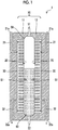
Fig. 1 is a cross-sectional view showing an example of a configuration of a cell culture apparatus 1 according to a first embodiment of the disclosed technique.Fig. 1 shows aculture vessel 50 for containing acell suspension 60 containing cells to be cultured using the cell culture apparatus 1 and a medium, together with the cell culture apparatus 1. Theculture vessel 50 has a bag shape configured to include a film which is gas-permeable. At one end part of theculture vessel 50, agas flow port 51 is provided for allowing a gas for adjusting pressure inside theculture vessel 50 to flow into theculture vessel 50 or out of theculture vessel 50. At the other end part of theculture vessel 50, aliquid flow port 52 is provided for allowing thecell suspension 60 to flow into theculture vessel 50 or out of theculture vessel 50. - The cell culture apparatus 1 includes a
heat transfer medium 10 that is in contact with a surface of theculture vessel 50. Theheat transfer medium 10 includes afirst part 11 disposed on one surface side of theculture vessel 50 and asecond part 12 disposed on the other surface side of theculture vessel 50. When using the cell culture apparatus 1, theculture vessel 50 is sandwiched between thefirst part 11 and thesecond part 12 of theheat transfer medium 10. Theheat transfer medium 10 is made of a material having a relatively high thermal conductivity, such as metal and resin. - Each of the
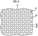
first part 11 and thesecond part 12 of theheat transfer medium 10 has a plurality ofhole parts 20 on a contact surface S1 in contact with theculture vessel 50.Fig. 2 is a plan view showing an example of a structure of the contact surface S1 of theheat transfer medium 10 in contact with theculture vessel 50. On the contact surface S1 of theheat transfer medium 10 in contact with theculture vessel 50, a plurality ofhole parts 20 is uniformly provided over the entire contact surface S1. A shape of the plurality ofhole parts 20 is not particularly limited, and may be circular, for example. It is preferable that a diameter a of thehole part 20 is in a size in which a film forming theculture vessel 50 does not sink into thehole part 20. For example, in a case where a thickness of the film forming theculture vessel 50 is t, it is preferable that the diameter a of thehole part 20 satisfies a ≤ 2.5t. As shown inFig. 1 , the plurality ofhole parts 20 communicate with each other via acommunication passage 30. - An
air supply port 31a is provided at one end part of each of thefirst part 11 and thesecond part 12 of theheat transfer medium 10. Theair supply port 31a is connected to thecommunication passage 30 via anair supply passage 31 provided inside theheat transfer medium 10. In addition, anexhaust port 32a is provided at the other end part of each of thefirst part 11 and thesecond part 12 of theheat transfer medium 10. Theexhaust port 32a is connected to thecommunication passage 30 via anexhaust passage 32 provided inside theheat transfer medium 10. That is, each of the plurality ofhole parts 20 communicates with both theair supply port 31a and theexhaust port 32a. - The plurality of
hole parts 20 may be formed, for example, by machining a base material forming theheat transfer medium 10. In this case, it is preferable that the plurality ofhole parts 20 is uniformly and regularly disposed on the contact surface S1 of theheat transfer medium 10, and it is preferable that a part of theheat transfer medium 10 in contact with the culture vessel 50 (a part other than the hole parts 20) extends uniformly on the contact surface S1 of theheat transfer medium 10. In addition, as theheat transfer medium 10, a porous material such as a metal sintered body may be used. In this case, a plurality of voids formed in the porous material function as thehole parts 20. In addition, as theheat transfer medium 10, an aggregate of a plurality of fibrous members, such as steel wool may be used. In this case, a plurality of voids formed between the fibrous members function as thehole parts 20. - The
heat transfer medium 10 is configured such that a distance between thefirst part 11 and thesecond part 12 maintains a constant distance according to the thickness of theculture vessel 50. Accordingly, a deformation of theculture vessel 50 sandwiched between thefirst part 11 and thesecond part 12 is regulated. - Hereinafter, an example of a cell culture method using the cell culture apparatus 1 will be described. First, the
culture vessel 50 is disposed between thefirst part 11 and thesecond part 12 of theheat transfer medium 10. Theculture vessel 50 is disposed so that thegas flow port 51 is positioned vertically upward and theliquid flow port 52 is positioned vertically downward. - Next, the
cell suspension 60 containing a plurality of cells to be cultured and a medium is allowed to flow into theculture vessel 50 through theliquid flow port 52. Thereafter, a gas is allowed to flow into theculture vessel 50 through thegas flow port 51. It is preferable that pressure inside theculture vessel 50 is kept at a state of the same as or higher than the pressure of an atmosphere outside theculture vessel 50. Accordingly, theculture vessel 50 is kept in close contact with the respective contact surfaces S1 of thefirst part 11 and thesecond part 12 of theheat transfer medium 10. A deformation of theculture vessel 50 due to the inflow of thecell suspension 60 into theculture vessel 50 is regulated by sandwiching theculture vessel 50 between thefirst part 11 and thesecond part 12. Thus, the thickness of theculture vessel 50 containing thecell suspension 60 is substantially uniform in the entire vertical direction. - Next, the temperature-adjusted and composition-adjusted gas is introduced into the
heat transfer medium 10 through the respectiveair supply ports 31 a of thefirst part 11 and thesecond part 12 of theheat transfer medium 10. The temperature of the gas introduced into theheat transfer medium 10 is adjusted to a temperature (for example, 37°C) suitable for promoting the growth of cells contained in theculture vessel 50, for example. Further, the gas introduced into theheat transfer medium 10 contains, for example, oxygen and carbon dioxide necessary for promoting the growth of the cells contained in theculture vessel 50, and a mixing ratio thereof is adjusted. The gas introduced into theheat transfer medium 10 may contain water vapor. - The gas introduced from the
air supply port 31a spreads throughout theheat transfer medium 10 via theair supply passage 31 and thecommunication passage 30. A part of the gas is discharged from each of thehole parts 20, and a part of the remaining gas is discharged from theexhaust port 32a via theexhaust passage 32. The temperature-adjusted gas spreads throughout theheat transfer medium 10, so that the temperature of theheat transfer medium 10 quickly rises to a desired temperature (for example, 37°C). Since the contact surfaces S1 of thefirst part 11 and thesecond part 12 of theheat transfer medium 10 are in contact with theculture vessel 50, the temperature of thecell suspension 60 contained in theculture vessel 50 quickly rises to the desired temperature (for example, 37°C). In addition, since the part of theheat transfer medium 10 in contact with the culture vessel 50 (the part other than the hole parts 20) extends uniformly over the entire contact surface S1, occurrence of temperature unevenness of thecell suspension 60 contained in theculture vessel 50 is suppressed and it is possible to enhance the temperature uniformity of thecell suspension 60. - Further, the temperature-adjusted and composition-adjusted gas discharged from the plurality of
hole parts 20 provided in the contact surface S1 of theheat transfer medium 10 is supplied to the surface of theculture vessel 50 which is gas-permeable, permeates into theculture vessel 50, and is taken into thecell suspension 60. The composition-adjusted gas is taken into thecell suspension 60 to promote the growth of the cells. - In a case where the
cell suspension 60 contained in theculture vessel 50 is allowed to flow out of theliquid flow port 52, the gas is introduced into theculture vessel 50 to pressurize the inside of theculture vessel 50, for example. Expansion of theculture vessel 50 due to the pressurization inside theculture vessel 50 is suppressed by sandwiching theculture vessel 50 between thefirst part 11 and thesecond part 12 of theheat transfer medium 10. Accordingly, it becomes easy to control the pressure inside theculture vessel 50, and it becomes easy to control the outflow amount of thecell suspension 60 from theculture vessel 50. - As described above, the cell culture apparatus 1 according to the embodiment of the disclosed technique includes the
heat transfer medium 10 having the plurality ofhole parts 20 on the contact surface S1 with theculture vessel 50, and allows the temperature-adjusted and composition-adjusted gas to flow through the gap which is formed by the contact surface S1 of theheat transfer medium 10 being brought into contact with theculture vessel 50. The heat of temperature-adjusted gas is conducted to thecell suspension 60 contained in theculture vessel 50 via theheat transfer medium 10, and the temperature of thecell suspension 60 rises to a desired temperature. - Since the
heat transfer medium 10 formed of a solid material has a smaller specific heat than that of the gas, the temperature rising rate of thecell suspension 60 can be enhanced by raising the temperature of thecell suspension 60 via theheat transfer medium 10, comparing to a case of using a general incubator. Accordingly, it possible to suppress the time during which the cells are exposed to the low temperature from being prolonged, and it is possible to improve proliferation and a survival rate of the cells. - In addition, a part of the
heat transfer medium 10 in contact with the culture vessel 50 (the part other than the hole parts 20) extends uniformly over the entire contact surface S1. In other words, theheat transfer medium 10 is in contact with theculture vessel 50 without deviation. Accordingly, occurrence of temperature unevenness of thecell suspension 60 contained in theculture vessel 50 is suppressed and it is possible to enhance the temperature uniformity of thecell suspension 60. - As described above, according to the cell culture apparatus 1 according to the embodiment of the disclosed technique, it is possible to improve the temperature rising rate of a temperature rising target and enhance the temperature uniformity of the temperature rising target. In addition, it is possible to carry out a temperature control of the
cell suspension 60 and gas supply to thecell suspension 60 in parallel. The cell culture apparatus 1 according to an embodiment of the disclosed technique has a remarkable effect, particularly in a case of being applied to a large-scale culture in which a cell suspension is contained in a large-sized culture vessel to culture cells. - In addition, the expansion of the
culture vessel 50 due to the pressurization inside theculture vessel 50 is suppressed by sandwiching theculture vessel 50 between thefirst part 11 and thesecond part 12 of theheat transfer medium 10. Accordingly, it becomes easy to control the pressure inside theculture vessel 50, and it becomes easy to control the outflow amount of thecell suspension 60 from theculture vessel 50. -
Fig. 3 is a cross-sectional view showing an example of a configuration of acell culture apparatus 1A according to a second embodiment of the disclosed technique. Thecell culture apparatus 1A includes aheater 40 attached to theheat transfer medium 10. Theheater 40 is provided on each of back surfaces S2 opposite to the contact surfaces S1 respectively of thefirst part 11 and thesecond part 12 of theheat transfer medium 10 with theculture vessel 50. - The
heater 40 is adjusted to a temperature (for example, 37°C) suitable for promoting the growth of cells contained in theculture vessel 50. The heat generated from theheater 40 is conducted to thecell suspension 60 contained in theculture vessel 50 via theheat transfer medium 10, and the temperature of thecell suspension 60 rises to a desired temperature. It is noted that, in order to heat theheat transfer medium 10, a temperature-adjusted gas may be introduced into theheat transfer medium 10 from theair supply port 31a. - According to the
cell culture apparatus 1A according to the present embodiment, as in the cell culture apparatus 1 according to the first embodiment, it is possible to improve the temperature rising rate of a temperature rising target and enhance the temperature uniformity of the temperature rising target. In addition, it is possible to carry out a temperature control of thecell suspension 60 and gas supply to thecell suspension 60 in parallel. In addition, according to thecell culture apparatus 1A according to the present embodiment, theheat transfer medium 10 is heated by theheater 40. Therefore, the temperature rising rate of theheat transfer medium 10 can be enhanced, comparing to a case where theheat transfer medium 10 is heated by only the temperature-adjusted gas. -
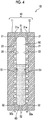
Fig. 4 is a cross-sectional view showing an example of a configuration of acell culture apparatus 1B according to a third embodiment of the disclosed technique. - Each of the
first part 11 and thesecond part 12 of theheat transfer medium 10 has arecess part 21 and aprotrusion part 22 on the contact surface S1 in contact with theculture vessel 50.Figs. 5A and 5B are perspective views showing an example of a structure of the contact surface S1 of theheat transfer medium 10, respectively. On the contact surface S1 of theheat transfer medium 10, a plurality of theprotrusion parts 22 are uniformly provided over the entire contact surface S1. A shape of the plurality ofprotrusion parts 22 is not particularly limited, and may be, for example, a rectangular parallelepiped as shown inFig. 5A or a columnar shape as shown inFig. 5B . Therecess part 21 is formed in the gap between the plurality ofprotrusion parts 22, and respective portions of therecess part 21 communicate with each other. -
Fig. 6 is an enlarged cross-sectional view showing a contact part between theheat transfer medium 10 and theculture vessel 50. It is preferable that a width w and a depth d of therecess part 21 which is formed on the contact surface S1 of theheat transfer medium 10 with theculture vessel 50 are in a size in which afilm 53 forming theculture vessel 50 does not close therecess part 21. For example, in a case where a thickness of thefilm 53 forming theculture vessel 50 is t, it is preferable that the width w of therecess part 21 satisfies w ≤ 2.5t. In addition, it is preferable that the depth d of therecess part 21 satisfies d ≥ 0.8t. The width w of therecess part 21 corresponds to the distance of a part in which a distance between theadjacent protrusion parts 22 is the longest. In addition, the depth d of therecess part 21 corresponds to the distance between a top surface of theprotrusion part 22 and a bottom surface of therecess part 21. - As shown in
Fig. 4 , theair supply port 31a is provided at one end part of each of thefirst part 11 and thesecond part 12 of theheat transfer medium 10. Theair supply port 31a is connected to therecess part 21 disposed at one end side of theheat transfer medium 10, via theair supply passage 31 provided inside theheat transfer medium 10. In addition, anexhaust port 32a is provided at the other end part of each of thefirst part 11 and thesecond part 12 of theheat transfer medium 10. Theexhaust port 32a is connected to therecess part 21 disposed at the other end side of theheat transfer medium 10, via theexhaust passage 32 provided inside theheat transfer medium 10. As described above, the respective portions of therecess part 21 are in communication with each other, and the gas introduced from theair supply port 31a flows to the respective portions of therecess part 21. - An uneven structure including the
recess part 21 and theprotrusion parts 22 formed on the contact surface S1 of theheat transfer medium 10 with theculture vessel 50 may be formed by, for example, machining a base material forming theheat transfer medium 10. In this case, it is preferable that therecess part 21 and theprotrusion parts 22 is uniformly and regularly disposed on the contact surface S1 of theheat transfer medium 10, and it is preferable that parts of theheat transfer medium 10 in contact with the culture vessel 50 (that is, the protrusion part 22) extend uniformly on the contact surface S1 of theheat transfer medium 10. Theheat transfer medium 10 is configured such that a distance between thefirst part 11 and thesecond part 12 maintains a constant distance according to the thickness of theculture vessel 50. - Hereinafter, an example of a cell culture method using the
cell culture apparatus 1B will be described. First, theculture vessel 50 is disposed between thefirst part 11 and thesecond part 12 of theheat transfer medium 10. Theculture vessel 50 is disposed so that thegas flow port 51 is positioned vertically upward and theliquid flow port 52 is positioned vertically downward. - Next, the
cell suspension 60 containing a plurality of cells to be cultured and a medium is allowed to flow into theculture vessel 50 through theliquid flow port 52. Thereafter, a gas is allowed to flow into theculture vessel 50 through thegas flow port 51. It is preferable that pressure inside theculture vessel 50 is kept at a state of the same as or higher than the pressure of an atmosphere outside theculture vessel 50. Accordingly, theculture vessel 50 is kept in close contact with the respective contact surfaces S1 of thefirst part 11 and thesecond part 12 of theheat transfer medium 10. A deformation of theculture vessel 50 due to the inflow of thecell suspension 60 into theculture vessel 50 is regulated by sandwiching theculture vessel 50 between thefirst part 11 and thesecond part 12. Thus, the thickness of theculture vessel 50 containing thecell suspension 60 is substantially uniform in the entire vertical direction. - Next, the temperature-adjusted and composition-adjusted gas is introduced into the
heat transfer medium 10 through the respectiveair supply ports 31a of thefirst part 11 and thesecond part 12 of theheat transfer medium 10. The temperature of the gas introduced into theheat transfer medium 10 is adjusted to a temperature (for example, 37°C) suitable for promoting the growth of cells contained in theculture vessel 50, for example. Further, the gas introduced into theheat transfer medium 10 contains, for example, oxygen and carbon dioxide necessary for promoting the growth of the cells contained in theculture vessel 50, and a mixing ratio thereof is adjusted. The gas introduced into theheat transfer medium 10 may contain water vapor. - The gas introduced from the
air supply port 31a is supplied to therecess part 21 formed on the contact surface S1 of theheat transfer medium 10 via theair supply passage 31, flows along therecess part 21, spreads throughout theheat transfer medium 10, and is discharged from theexhaust port 32a via theexhaust passage 32. - The temperature-adjusted gas spreads throughout the
heat transfer medium 10, so that the temperature of theheat transfer medium 10 quickly rises to a desired temperature (for example, 37°C). Since the contact surfaces S1 of thefirst part 11 and thesecond part 12 of theheat transfer medium 10 are in contact with theculture vessel 50, the temperature of thecell suspension 60 contained in theculture vessel 50 quickly rises to the desired temperature (for example, 37°C). In addition, therecess part 21 and theprotrusion parts 22 are uniformity and regularly disposed on the contact surface S1 of theheat transfer medium 10, and parts of theheat transfer medium 10 in contact with the culture vessel 50 (that is, protrusion parts 22) extend uniformly on the contact surface S1 of theheat transfer medium 10. Therefore, occurrence of temperature unevenness of thecell suspension 60 contained in theculture vessel 50 is suppressed and it is possible to enhance the temperature uniformity of thecell suspension 60. - Further, the gas flowing along the
recess part 21 provided in the contact surface S1 of theheat transfer medium 10 is supplied to the surface of theculture vessel 50 which is gas-permeable, permeates into theculture vessel 50, and is taken into thecell suspension 60. The composition-adjusted gas is taken into thecell suspension 60 to promote the growth of the cells. - In a case where the
cell suspension 60 contained in theculture vessel 50 is allowed to flow out of theliquid flow port 52, the gas is introduced into theculture vessel 50 through thegas flow port 51 to pressurize the inside of theculture vessel 50, for example. Expansion of theculture vessel 50 due to the pressurization inside theculture vessel 50 is suppressed by sandwiching theculture vessel 50 between thefirst part 11 and thesecond part 12 of theheat transfer medium 10. Accordingly, it becomes easy to control the pressure inside theculture vessel 50, and it becomes easy to control the outflow amount of thecell suspension 60 from theculture vessel 50. - As described above, the
cell culture apparatus 1B according to the present embodiment includes theheat transfer medium 10 having therecess part 21 and theprotrusion parts 22 on the contact surface S1 with theculture vessel 50, and allows the temperature-adjusted and composition-adjusted gas to flow through the gap which is formed by the contact surface S1 of theheat transfer medium 10 being brought into contact with theculture vessel 50. The heat of temperature-adjusted gas is conducted to thecell suspension 60 contained in theculture vessel 50 via theheat transfer medium 10, and the temperature of thecell suspension 60 rises to a desired temperature. - According to the
cell culture apparatus 1B according to the present embodiment, as in the cell culture apparatus 1 according to the first embodiment, it is possible to improve the temperature rising rate of a temperature rising target and enhance the temperature uniformity of the temperature rising target. In addition, it is possible to carry out a temperature control of thecell suspension 60 and gas supply to thecell suspension 60 in parallel. - In addition, the expansion of the
culture vessel 50 due to the pressurization inside theculture vessel 50 is suppressed by sandwiching theculture vessel 50 between thefirst part 11 and thesecond part 12 of theheat transfer medium 10. Accordingly, it becomes easy to control the pressure inside theculture vessel 50, and it becomes easy to control the outflow amount of thecell suspension 60 from theculture vessel 50. -
Fig. 7 is a cross-sectional view showing an example of a configuration of acell culture apparatus 1C according to a fourth embodiment of the disclosed technique. Thecell culture apparatus 1C includes theheater 40 attached to theheat transfer medium 10. Theheater 40 is provided on each of back surfaces S2 opposite to the contact surfaces S1 respectively of thefirst part 11 and thesecond part 12 of theheat transfer medium 10 with theculture vessel 50. - The
heater 40 is adjusted to a temperature (for example, 37°C) suitable for promoting the growth of cells contained in theculture vessel 50. The heat generated from theheater 40 is conducted to thecell suspension 60 contained in theculture vessel 50 via theheat transfer medium 10, and the temperature of thecell suspension 60 rises to a desired temperature. It is noted that, in order to heat theheat transfer medium 10, a temperature-adjusted gas may be introduced into theheat transfer medium 10 from theair supply port 31a. - According to the
cell culture apparatus 1C according to the present embodiment, as in the cell culture apparatus 1 according to the first embodiment, it is possible to improve the temperature rising rate of a temperature rising target and enhance the temperature uniformity of the temperature rising target. In addition, it is possible to carry out a temperature control of thecell suspension 60 and gas supply to thecell suspension 60 in parallel. In addition, according to thecell culture apparatus 1C according to the present embodiment, theheat transfer medium 10 is heated by theheater 40. Therefore, the temperature rising rate of theheat transfer medium 10 can be enhanced, comparing to a case where theheat transfer medium 10 is heated by only the temperature-adjusted gas. -
Fig. 8 is a view showing an example of a configuration of acell culture system 100 according to a fifth embodiment of the disclosed technique. Thecell culture system 100 includes the cell culture apparatus 1 and ahousing container 70 that houses the cell culture apparatus 1. Thehousing container 70 has a function as an incubator, and has a temperature control mechanism that keeps the temperature inside thehousing container 70 constant (for example, 37°C). In addition, a composition-adjusted gas containing oxygen and carbon dioxide is introduced into thehousing container 70. - According to the
culture system 100 of the present embodiment, it is possible to suppress a temperature change inside theculture vessel 50 and a composition change of the gas introduced into theculture vessel 50. - As shown in
Fig. 9 , a plurality of the cell culture apparatuses 1 may be housed inside thehousing container 70. In addition, thecell culture system 100 may be configured such that the cell suspension contained in theculture vessel 50 can be transferred between the plurality of cell culture apparatuses 1 housed inside thehousing container 70. Accordingly, it is possible to agitate the cell suspension in theculture vessel 50, in the plurality of cell culture apparatuses 1 housed in thehousing container 70. - In the present embodiment, the case where one or more cell culture apparatuses 1 are housed in the
housing container 70 is illustrated. However, it is also possible to adopt thecell culture apparatus 1A (Fig. 3 ), thecell culture apparatus 1B (Fig. 4 ), and thecell culture apparatus 1C (Fig. 7 ), instead of the cell culture apparatus 1. - The entire disclosure of Japanese Patent Application No.
2018-133203 - All documents, patent applications, and technical standards described herein are incorporated by reference herein to the same extent as in a case where each of the documents, patent applications, and technical standards are specifically and individually described to be incorporated by reference.
-
- 1, 1A, 1B, 1C: cell culture apparatus
- 10: heat transfer medium
- 11: first part
- 12: second part
- 20: hole part
- 21: recess part
- 22: protrusion part
- 30: communication passage
- 31: air supply passage
- 31a: air supply port
- 32: exhaust passage
- 32a: exhaust port
- 40: heater
- 50: culture vessel
- 51: gas flow port
- 52: liquid flow port
- 53: film
- 60: cell suspension
- 70: housing container
- 100: cell culture system
- S1: contact surface
- S2: back surface
Claims (13)
- A cell culture apparatus comprising:a heat transfer medium having a recess part or a plurality of hole parts in a contact surface with a culture vessel for containing a cell suspension; andan air supply port which communicates with the recess part or each of the plurality of hole parts and to which a gas is supplied.
- The cell culture apparatus according to claim 1,
wherein the recess part or the plurality of hole parts is disposed uniformly over an entire contact surface of the heat transfer medium. - The cell culture apparatus according to claim 1 or 2,
wherein the heat transfer medium is configured to include a porous material. - The cell culture apparatus according to claim 1 or 2,
wherein the contact surface of the heat transfer medium has an uneven structure including the recess part and a protrusion part. - The cell culture apparatus according to any one of claims 1 to 4,
wherein a part of the heat transfer medium in contact with the culture vessel extends uniformly on the contact surface of the heat transfer medium. - The cell culture apparatus according to any one of claims 1 to 5,
wherein the heat transfer medium includes a first part provided on one surface side of the culture vessel and a second part provided on the other surface side of the culture vessel opposite to the one surface. - The cell culture apparatus according to any one of claims 1 to 6, further comprising:
a heater attached to the heat transfer medium. - The cell culture apparatus according to claim 4,
wherein a width of the recess part is at most 2.5 times a thickness of a material forming the culture vessel, and a depth of the recess part is at least 0.8 times the thickness of the material forming the culture vessel. - A cell culture method comprising:bringing a culture vessel, in which a cell suspension is contained and which is gas-permeable, into contact with a surface of a heat transfer medium which is heated and has a recess part or a plurality of hole parts on the surface; andallowing a gas to flow through a gap which is formed by the surface of the heat transfer medium being brought into contact with the culture vessel.
- The cell culture method according to claim 9,
wherein the heat transfer medium is heated using a temperature-adjusted gas as the gas. - The cell culture method according to claim 9,
wherein the heat transfer medium is heated by a heater attached to the heat transfer medium. - The cell culture method according to any one of claims 9 to 11,
wherein a composition-adjusted gas is used as the gas. - The cell culture method according to any one of claims 9 to 12,wherein the heat transfer medium includes a first part provided on one surface side of the culture vessel and a second part provided on the other surface side of the culture vessel opposite to the one surface, andthe culture vessel is sandwiched between the first part and the second part.
Applications Claiming Priority (2)
| Application Number | Priority Date | Filing Date | Title |
|---|---|---|---|
| JP2018133203 | 2018-07-13 | ||
| PCT/JP2019/022762 WO2020012845A1 (en) | 2018-07-13 | 2019-06-07 | Cell culture device and cell culture method |
Publications (3)
| Publication Number | Publication Date |
|---|---|
| EP3822337A1 true EP3822337A1 (en) | 2021-05-19 |
| EP3822337A4 EP3822337A4 (en) | 2021-08-04 |
| EP3822337B1 EP3822337B1 (en) | 2022-05-04 |
Family
ID=69141506
Family Applications (1)
| Application Number | Title | Priority Date | Filing Date |
|---|---|---|---|
| EP19834528.2A Active EP3822337B1 (en) | 2018-07-13 | 2019-06-07 | Cell culture device and cell culture method |
Country Status (4)
| Country | Link |
|---|---|
| US (1) | US20210102158A1 (en) |
| EP (1) | EP3822337B1 (en) |
| JP (1) | JP7482774B2 (en) |
| WO (1) | WO2020012845A1 (en) |
Family Cites Families (15)
| Publication number | Priority date | Publication date | Assignee | Title |
|---|---|---|---|---|
| DE558064C (en) * | 1932-09-03 | Dipl Dr Ing Rudolf Horch | Apparatus for tempering fermenting liquids | |
| JPS5824175B2 (en) * | 1978-11-10 | 1983-05-19 | 日本ポリエステル株式会社 | Jacket type synthetic resin container |
| DE4108744C1 (en) * | 1991-03-18 | 1992-08-27 | Atz Energie Umwelt Stroemungstechnik | Gas heating jacketed regenerator with heat storage medium - has central chamber surrounded by layer of pebbles or granular material |
| US5763267A (en) * | 1996-04-16 | 1998-06-09 | Advanced Tissue Sciences | Apparatus for the large scale growth and packaging of cell suspensions and three-dimensional tissue cultures |
| DE10025012B4 (en) * | 2000-05-22 | 2014-02-27 | Qiagen Gmbh | Temperable reaction vessel |
| JP2002065251A (en) * | 2000-08-30 | 2002-03-05 | Sumitomo Bakelite Co Ltd | Method for thawing animal cell |
| US9109193B2 (en) * | 2007-07-30 | 2015-08-18 | Ge Healthcare Bio-Sciences Corp. | Continuous perfusion bioreactor system |
| JP5282930B2 (en) * | 2007-10-09 | 2013-09-04 | 住友電気工業株式会社 | Optical element temperature characteristic inspection system |
| JP5589589B2 (en) * | 2010-06-17 | 2014-09-17 | 富士通株式会社 | Thermoelectric element and method for manufacturing thermoelectric element |
| US8668886B2 (en) * | 2011-04-24 | 2014-03-11 | Therapeutic Proteins International, LLC | Separative bioreactor |
| JP2013085534A (en) * | 2011-10-20 | 2013-05-13 | Eco Renaissance Entec:Kk | Method for culturing microalgae |
| CA2863050C (en) | 2012-01-13 | 2022-10-04 | Ge Healthcare Bio-Sciences Corp. | Biological reactor comprising a single use flexible container and heat exchange module |
| JP6554364B2 (en) * | 2015-08-28 | 2019-07-31 | 株式会社神鋼環境ソリューション | Algal culture method and paramylon production facility |
| US20170191015A1 (en) * | 2016-01-04 | 2017-07-06 | Therapeutic Proteins International, LLC | Gas heating apparatus for disposable bioreactor |
| JP6901116B2 (en) | 2017-02-15 | 2021-07-14 | かがつう株式会社 | lighting equipment |
-
2019
- 2019-06-07 EP EP19834528.2A patent/EP3822337B1/en active Active
- 2019-06-07 WO PCT/JP2019/022762 patent/WO2020012845A1/en not_active Ceased
- 2019-06-07 JP JP2020530040A patent/JP7482774B2/en active Active
-
2020
- 2020-12-15 US US17/123,057 patent/US20210102158A1/en not_active Abandoned
Also Published As
| Publication number | Publication date |
|---|---|
| JPWO2020012845A1 (en) | 2021-06-24 |
| US20210102158A1 (en) | 2021-04-08 |
| WO2020012845A1 (en) | 2020-01-16 |
| EP3822337A4 (en) | 2021-08-04 |
| JP7482774B2 (en) | 2024-05-14 |
| EP3822337B1 (en) | 2022-05-04 |
Similar Documents
| Publication | Publication Date | Title |
|---|---|---|
| CN202063993U (en) | Large-scale MOCVD (metal organic chemical vapor deposition) system for film photovoltaic device | |
| KR101645262B1 (en) | Gas dispersion apparatus | |
| KR20190075898A (en) | A method for manufacturing a container, a manufacturing apparatus therefor, and a cell culture container, a cell culture method, a method for manufacturing a cell culture container, and a device for manufacturing a cell culture container | |
| US10363528B2 (en) | Mixing and thawing device | |
| WO1997038777A1 (en) | Apparatus for the large scale growth and packaging of cell suspensions and three-dimensional tissue cultures | |
| TW200817263A (en) | Multiple slot load lock chamber and method of operation | |
| US6727089B2 (en) | Culturing chamber on microscope stage | |
| JPWO2007122814A1 (en) | Multi-well incubation apparatus and analysis method using the same | |
| EP3822337B1 (en) | Cell culture device and cell culture method | |
| JP4787636B2 (en) | High pressure processing equipment | |
| CN104131351B (en) | A kind of industrialized unit and method for preparing nitride single crystal material | |
| CN111972398A (en) | Cooling device for bioengineering | |
| JP2007043170A5 (en) | ||
| CN222119213U (en) | A culture box and a culture system | |
| CN110669668B (en) | Carbon dioxide incubator | |
| CN115558587A (en) | An in-situ culture device and control method for microbial observation | |
| Zainal Alam et al. | Establishment of temperature control scheme for microbioreactor operation using integrated microheater | |
| JP2018019652A (en) | Manufacturing method of vessel and manufacturing apparatus | |
| CN219490033U (en) | Closed cell culture board | |
| CN217809457U (en) | Temperature control carrying platform for high-throughput single-cell sequencing | |
| US12303903B2 (en) | Temperature controlled reactor | |
| CN118067973B (en) | A thermostatic patch clamp cell observation and recording system for cell experiments | |
| EP4488358A1 (en) | Apparatus and method for controllable handling of chemical and biological material | |
| TW201117265A (en) | Apparatus for forming film | |
| KR101255328B1 (en) | Chemical temperature controlling apparatus for treating substrate |
Legal Events
| Date | Code | Title | Description |
|---|---|---|---|
| STAA | Information on the status of an ep patent application or granted ep patent |
Free format text: STATUS: THE INTERNATIONAL PUBLICATION HAS BEEN MADE |
|
| PUAI | Public reference made under article 153(3) epc to a published international application that has entered the european phase |
Free format text: ORIGINAL CODE: 0009012 |
|
| STAA | Information on the status of an ep patent application or granted ep patent |
Free format text: STATUS: REQUEST FOR EXAMINATION WAS MADE |
|
| 17P | Request for examination filed |
Effective date: 20201229 |
|
| AK | Designated contracting states |
Kind code of ref document: A1 Designated state(s): AL AT BE BG CH CY CZ DE DK EE ES FI FR GB GR HR HU IE IS IT LI LT LU LV MC MK MT NL NO PL PT RO RS SE SI SK SM TR |
|
| A4 | Supplementary search report drawn up and despatched |
Effective date: 20210707 |
|
| RIC1 | Information provided on ipc code assigned before grant |
Ipc: C12M 1/00 20060101AFI20210630BHEP Ipc: C12M 1/04 20060101ALI20210630BHEP Ipc: C12M 3/00 20060101ALI20210630BHEP |
|
| DAV | Request for validation of the european patent (deleted) | ||
| DAX | Request for extension of the european patent (deleted) | ||
| GRAP | Despatch of communication of intention to grant a patent |
Free format text: ORIGINAL CODE: EPIDOSNIGR1 |
|
| STAA | Information on the status of an ep patent application or granted ep patent |
Free format text: STATUS: GRANT OF PATENT IS INTENDED |
|
| INTG | Intention to grant announced |
Effective date: 20220107 |
|
| GRAS | Grant fee paid |
Free format text: ORIGINAL CODE: EPIDOSNIGR3 |
|
| GRAA | (expected) grant |
Free format text: ORIGINAL CODE: 0009210 |
|
| STAA | Information on the status of an ep patent application or granted ep patent |
Free format text: STATUS: THE PATENT HAS BEEN GRANTED |
|
| AK | Designated contracting states |
Kind code of ref document: B1 Designated state(s): AL AT BE BG CH CY CZ DE DK EE ES FI FR GB GR HR HU IE IS IT LI LT LU LV MC MK MT NL NO PL PT RO RS SE SI SK SM TR |
|
| REG | Reference to a national code |
Ref country code: GB Ref legal event code: FG4D |
|
| REG | Reference to a national code |
Ref country code: CH Ref legal event code: EP |
|
| REG | Reference to a national code |
Ref country code: AT Ref legal event code: REF Ref document number: 1489080 Country of ref document: AT Kind code of ref document: T Effective date: 20220515 |
|
| REG | Reference to a national code |
Ref country code: IE Ref legal event code: FG4D Ref country code: DE Ref legal event code: R096 Ref document number: 602019014658 Country of ref document: DE |
|
| REG | Reference to a national code |
Ref country code: LT Ref legal event code: MG9D |
|
| REG | Reference to a national code |
Ref country code: NL Ref legal event code: MP Effective date: 20220504 |
|
| REG | Reference to a national code |
Ref country code: AT Ref legal event code: MK05 Ref document number: 1489080 Country of ref document: AT Kind code of ref document: T Effective date: 20220504 |
|
| PG25 | Lapsed in a contracting state [announced via postgrant information from national office to epo] |
Ref country code: SE Free format text: LAPSE BECAUSE OF FAILURE TO SUBMIT A TRANSLATION OF THE DESCRIPTION OR TO PAY THE FEE WITHIN THE PRESCRIBED TIME-LIMIT Effective date: 20220504 Ref country code: PT Free format text: LAPSE BECAUSE OF FAILURE TO SUBMIT A TRANSLATION OF THE DESCRIPTION OR TO PAY THE FEE WITHIN THE PRESCRIBED TIME-LIMIT Effective date: 20220905 Ref country code: NO Free format text: LAPSE BECAUSE OF FAILURE TO SUBMIT A TRANSLATION OF THE DESCRIPTION OR TO PAY THE FEE WITHIN THE PRESCRIBED TIME-LIMIT Effective date: 20220804 Ref country code: NL Free format text: LAPSE BECAUSE OF FAILURE TO SUBMIT A TRANSLATION OF THE DESCRIPTION OR TO PAY THE FEE WITHIN THE PRESCRIBED TIME-LIMIT Effective date: 20220504 Ref country code: LT Free format text: LAPSE BECAUSE OF FAILURE TO SUBMIT A TRANSLATION OF THE DESCRIPTION OR TO PAY THE FEE WITHIN THE PRESCRIBED TIME-LIMIT Effective date: 20220504 Ref country code: HR Free format text: LAPSE BECAUSE OF FAILURE TO SUBMIT A TRANSLATION OF THE DESCRIPTION OR TO PAY THE FEE WITHIN THE PRESCRIBED TIME-LIMIT Effective date: 20220504 Ref country code: GR Free format text: LAPSE BECAUSE OF FAILURE TO SUBMIT A TRANSLATION OF THE DESCRIPTION OR TO PAY THE FEE WITHIN THE PRESCRIBED TIME-LIMIT Effective date: 20220805 Ref country code: FI Free format text: LAPSE BECAUSE OF FAILURE TO SUBMIT A TRANSLATION OF THE DESCRIPTION OR TO PAY THE FEE WITHIN THE PRESCRIBED TIME-LIMIT Effective date: 20220504 Ref country code: BG Free format text: LAPSE BECAUSE OF FAILURE TO SUBMIT A TRANSLATION OF THE DESCRIPTION OR TO PAY THE FEE WITHIN THE PRESCRIBED TIME-LIMIT Effective date: 20220804 Ref country code: AT Free format text: LAPSE BECAUSE OF FAILURE TO SUBMIT A TRANSLATION OF THE DESCRIPTION OR TO PAY THE FEE WITHIN THE PRESCRIBED TIME-LIMIT Effective date: 20220504 |
|
| PG25 | Lapsed in a contracting state [announced via postgrant information from national office to epo] |
Ref country code: RS Free format text: LAPSE BECAUSE OF FAILURE TO SUBMIT A TRANSLATION OF THE DESCRIPTION OR TO PAY THE FEE WITHIN THE PRESCRIBED TIME-LIMIT Effective date: 20220504 Ref country code: PL Free format text: LAPSE BECAUSE OF FAILURE TO SUBMIT A TRANSLATION OF THE DESCRIPTION OR TO PAY THE FEE WITHIN THE PRESCRIBED TIME-LIMIT Effective date: 20220504 Ref country code: LV Free format text: LAPSE BECAUSE OF FAILURE TO SUBMIT A TRANSLATION OF THE DESCRIPTION OR TO PAY THE FEE WITHIN THE PRESCRIBED TIME-LIMIT Effective date: 20220504 Ref country code: IS Free format text: LAPSE BECAUSE OF FAILURE TO SUBMIT A TRANSLATION OF THE DESCRIPTION OR TO PAY THE FEE WITHIN THE PRESCRIBED TIME-LIMIT Effective date: 20220904 |
|
| PG25 | Lapsed in a contracting state [announced via postgrant information from national office to epo] |
Ref country code: SM Free format text: LAPSE BECAUSE OF FAILURE TO SUBMIT A TRANSLATION OF THE DESCRIPTION OR TO PAY THE FEE WITHIN THE PRESCRIBED TIME-LIMIT Effective date: 20220504 Ref country code: SK Free format text: LAPSE BECAUSE OF FAILURE TO SUBMIT A TRANSLATION OF THE DESCRIPTION OR TO PAY THE FEE WITHIN THE PRESCRIBED TIME-LIMIT Effective date: 20220504 Ref country code: RO Free format text: LAPSE BECAUSE OF FAILURE TO SUBMIT A TRANSLATION OF THE DESCRIPTION OR TO PAY THE FEE WITHIN THE PRESCRIBED TIME-LIMIT Effective date: 20220504 Ref country code: ES Free format text: LAPSE BECAUSE OF FAILURE TO SUBMIT A TRANSLATION OF THE DESCRIPTION OR TO PAY THE FEE WITHIN THE PRESCRIBED TIME-LIMIT Effective date: 20220504 Ref country code: EE Free format text: LAPSE BECAUSE OF FAILURE TO SUBMIT A TRANSLATION OF THE DESCRIPTION OR TO PAY THE FEE WITHIN THE PRESCRIBED TIME-LIMIT Effective date: 20220504 Ref country code: DK Free format text: LAPSE BECAUSE OF FAILURE TO SUBMIT A TRANSLATION OF THE DESCRIPTION OR TO PAY THE FEE WITHIN THE PRESCRIBED TIME-LIMIT Effective date: 20220504 Ref country code: CZ Free format text: LAPSE BECAUSE OF FAILURE TO SUBMIT A TRANSLATION OF THE DESCRIPTION OR TO PAY THE FEE WITHIN THE PRESCRIBED TIME-LIMIT Effective date: 20220504 |
|
| REG | Reference to a national code |
Ref country code: CH Ref legal event code: PL |
|
| REG | Reference to a national code |
Ref country code: DE Ref legal event code: R097 Ref document number: 602019014658 Country of ref document: DE |
|
| REG | Reference to a national code |
Ref country code: BE Ref legal event code: MM Effective date: 20220630 |
|
| PG25 | Lapsed in a contracting state [announced via postgrant information from national office to epo] |
Ref country code: MC Free format text: LAPSE BECAUSE OF FAILURE TO SUBMIT A TRANSLATION OF THE DESCRIPTION OR TO PAY THE FEE WITHIN THE PRESCRIBED TIME-LIMIT Effective date: 20220504 |
|
| PLBE | No opposition filed within time limit |
Free format text: ORIGINAL CODE: 0009261 |
|
| STAA | Information on the status of an ep patent application or granted ep patent |
Free format text: STATUS: NO OPPOSITION FILED WITHIN TIME LIMIT |
|
| PG25 | Lapsed in a contracting state [announced via postgrant information from national office to epo] |
Ref country code: AL Free format text: LAPSE BECAUSE OF FAILURE TO SUBMIT A TRANSLATION OF THE DESCRIPTION OR TO PAY THE FEE WITHIN THE PRESCRIBED TIME-LIMIT Effective date: 20220504 |
|
| 26N | No opposition filed |
Effective date: 20230207 |
|
| PG25 | Lapsed in a contracting state [announced via postgrant information from national office to epo] |
Ref country code: LU Free format text: LAPSE BECAUSE OF NON-PAYMENT OF DUE FEES Effective date: 20220607 Ref country code: LI Free format text: LAPSE BECAUSE OF NON-PAYMENT OF DUE FEES Effective date: 20220630 Ref country code: IE Free format text: LAPSE BECAUSE OF NON-PAYMENT OF DUE FEES Effective date: 20220607 Ref country code: CH Free format text: LAPSE BECAUSE OF NON-PAYMENT OF DUE FEES Effective date: 20220630 |
|
| PG25 | Lapsed in a contracting state [announced via postgrant information from national office to epo] |
Ref country code: SI Free format text: LAPSE BECAUSE OF FAILURE TO SUBMIT A TRANSLATION OF THE DESCRIPTION OR TO PAY THE FEE WITHIN THE PRESCRIBED TIME-LIMIT Effective date: 20220504 Ref country code: BE Free format text: LAPSE BECAUSE OF NON-PAYMENT OF DUE FEES Effective date: 20220630 |
|
| P01 | Opt-out of the competence of the unified patent court (upc) registered |
Effective date: 20230515 |
|
| PG25 | Lapsed in a contracting state [announced via postgrant information from national office to epo] |
Ref country code: IT Free format text: LAPSE BECAUSE OF FAILURE TO SUBMIT A TRANSLATION OF THE DESCRIPTION OR TO PAY THE FEE WITHIN THE PRESCRIBED TIME-LIMIT Effective date: 20220504 |
|
| PG25 | Lapsed in a contracting state [announced via postgrant information from national office to epo] |
Ref country code: MK Free format text: LAPSE BECAUSE OF FAILURE TO SUBMIT A TRANSLATION OF THE DESCRIPTION OR TO PAY THE FEE WITHIN THE PRESCRIBED TIME-LIMIT Effective date: 20220504 Ref country code: CY Free format text: LAPSE BECAUSE OF FAILURE TO SUBMIT A TRANSLATION OF THE DESCRIPTION OR TO PAY THE FEE WITHIN THE PRESCRIBED TIME-LIMIT Effective date: 20220504 |
|
| PG25 | Lapsed in a contracting state [announced via postgrant information from national office to epo] |
Ref country code: HU Free format text: LAPSE BECAUSE OF FAILURE TO SUBMIT A TRANSLATION OF THE DESCRIPTION OR TO PAY THE FEE WITHIN THE PRESCRIBED TIME-LIMIT; INVALID AB INITIO Effective date: 20190607 |
|
| PG25 | Lapsed in a contracting state [announced via postgrant information from national office to epo] |
Ref country code: TR Free format text: LAPSE BECAUSE OF FAILURE TO SUBMIT A TRANSLATION OF THE DESCRIPTION OR TO PAY THE FEE WITHIN THE PRESCRIBED TIME-LIMIT Effective date: 20220504 |
|
| PG25 | Lapsed in a contracting state [announced via postgrant information from national office to epo] |
Ref country code: MT Free format text: LAPSE BECAUSE OF FAILURE TO SUBMIT A TRANSLATION OF THE DESCRIPTION OR TO PAY THE FEE WITHIN THE PRESCRIBED TIME-LIMIT Effective date: 20220504 |
|
| PG25 | Lapsed in a contracting state [announced via postgrant information from national office to epo] |
Ref country code: BG Free format text: LAPSE BECAUSE OF FAILURE TO SUBMIT A TRANSLATION OF THE DESCRIPTION OR TO PAY THE FEE WITHIN THE PRESCRIBED TIME-LIMIT Effective date: 20220504 |
|
| PG25 | Lapsed in a contracting state [announced via postgrant information from national office to epo] |
Ref country code: BG Free format text: LAPSE BECAUSE OF FAILURE TO SUBMIT A TRANSLATION OF THE DESCRIPTION OR TO PAY THE FEE WITHIN THE PRESCRIBED TIME-LIMIT Effective date: 20220504 |
|
| PGFP | Annual fee paid to national office [announced via postgrant information from national office to epo] |
Ref country code: DE Payment date: 20250429 Year of fee payment: 7 |
|
| PGFP | Annual fee paid to national office [announced via postgrant information from national office to epo] |
Ref country code: GB Payment date: 20250501 Year of fee payment: 7 |
|
| PGFP | Annual fee paid to national office [announced via postgrant information from national office to epo] |
Ref country code: FR Payment date: 20250508 Year of fee payment: 7 |