EP3822165A1 - Standard unit meal box compartment including air chiller - Google Patents
Standard unit meal box compartment including air chiller Download PDFInfo
- Publication number
- EP3822165A1 EP3822165A1 EP20207307.8A EP20207307A EP3822165A1 EP 3822165 A1 EP3822165 A1 EP 3822165A1 EP 20207307 A EP20207307 A EP 20207307A EP 3822165 A1 EP3822165 A1 EP 3822165A1
- Authority
- EP
- European Patent Office
- Prior art keywords
- standard unit
- meal box
- air
- unit meal
- box compartment
- Prior art date
- Legal status (The legal status is an assumption and is not a legal conclusion. Google has not performed a legal analysis and makes no representation as to the accuracy of the status listed.)
- Granted
Links
Images



Classifications
-
- B—PERFORMING OPERATIONS; TRANSPORTING
- B64—AIRCRAFT; AVIATION; COSMONAUTICS
- B64D—EQUIPMENT FOR FITTING IN OR TO AIRCRAFT; FLIGHT SUITS; PARACHUTES; ARRANGEMENT OR MOUNTING OF POWER PLANTS OR PROPULSION TRANSMISSIONS IN AIRCRAFT
- B64D11/00—Passenger or crew accommodation; Flight-deck installations not otherwise provided for
- B64D11/04—Galleys
-
- A—HUMAN NECESSITIES
- A47—FURNITURE; DOMESTIC ARTICLES OR APPLIANCES; COFFEE MILLS; SPICE MILLS; SUCTION CLEANERS IN GENERAL
- A47B—TABLES; DESKS; OFFICE FURNITURE; CABINETS; DRAWERS; GENERAL DETAILS OF FURNITURE
- A47B77/00—Kitchen cabinets
-
- A—HUMAN NECESSITIES
- A47—FURNITURE; DOMESTIC ARTICLES OR APPLIANCES; COFFEE MILLS; SPICE MILLS; SUCTION CLEANERS IN GENERAL
- A47B—TABLES; DESKS; OFFICE FURNITURE; CABINETS; DRAWERS; GENERAL DETAILS OF FURNITURE
- A47B77/00—Kitchen cabinets
- A47B77/04—Provision for particular uses of compartments or other parts ; Compartments moving up and down, revolving parts
- A47B77/08—Provision for particular uses of compartments or other parts ; Compartments moving up and down, revolving parts for incorporating apparatus operated by power, including water power; for incorporating apparatus for cooking, cooling, or laundry purposes
-
- A—HUMAN NECESSITIES
- A47—FURNITURE; DOMESTIC ARTICLES OR APPLIANCES; COFFEE MILLS; SPICE MILLS; SUCTION CLEANERS IN GENERAL
- A47B—TABLES; DESKS; OFFICE FURNITURE; CABINETS; DRAWERS; GENERAL DETAILS OF FURNITURE
- A47B97/00—Furniture or accessories for furniture, not provided for in other groups of this subclass
-
- B—PERFORMING OPERATIONS; TRANSPORTING
- B64—AIRCRAFT; AVIATION; COSMONAUTICS
- B64D—EQUIPMENT FOR FITTING IN OR TO AIRCRAFT; FLIGHT SUITS; PARACHUTES; ARRANGEMENT OR MOUNTING OF POWER PLANTS OR PROPULSION TRANSMISSIONS IN AIRCRAFT
- B64D13/00—Arrangements or adaptations of air-treatment apparatus for aircraft crew or passengers, or freight space
- B64D13/06—Arrangements or adaptations of air-treatment apparatus for aircraft crew or passengers, or freight space the air being conditioned
- B64D2013/0603—Environmental Control Systems
- B64D2013/0629—Environmental Control Systems with subsystems for cooling food, catering or special loads
Definitions
- standard unit meal boxes are used to transport perishable food and beverages.
- the compartments, where the standard unit meal boxes are stowed, are unchilled, which limits the types of fresh food that may be carried without the risk of the fresh food spoiling and posing a health risk on long haul flights.
- inventions of the inventive concepts disclosed herein are directed to a system.
- the system may include an aircraft galley, which may include a standard unit meal box compartment configured to hold a standard unit meal box.
- the standard unit meal box compartment may include a door at a front of the standard unit meal box compartment and an air chiller near a rear of the standard unit meal box compartment.
- the air chiller may be configured to provide chilled air within the standard unit meal box compartment.
- inventions of the inventive concepts disclosed herein are directed to a method.
- the method may include providing an aircraft galley comprising a standard unit meal box compartment configured to hold at least one standard unit meal box, the standard unit meal box compartment comprising a door at a front of the standard unit meal box compartment and an air chiller near a rear of the standard unit meal box compartment.
- the method may further include providing, by the air chiller, chilled air within the standard unit meal box compartment.
- inventive concepts are not limited in their application to the details of construction and the arrangement of the components or steps or methodologies set forth in the following description or illustrated in the drawings.
- inventive concepts disclosed herein may be practiced without these specific details.
- well-known features may not be described in detail to avoid unnecessarily complicating the instant disclosure.
- inventive concepts disclosed herein are capable of other embodiments or of being practiced or carried out in various ways. Also, it is to be understood that the phraseology and terminology employed herein is for the purpose of description and should not be regarded as limiting.
- a letter following a reference numeral is intended to reference an embodiment of the feature or element that may be similar, but not necessarily identical, to a previously described element or feature bearing the same reference numeral (e.g., 1, 1a, 1b).
- reference numeral e.g. 1, 1a, 1b
- Such shorthand notations are used for purposes of convenience only, and should not be construed to limit the inventive concepts disclosed herein in any way unless expressly stated to the contrary.
- any reference to "one embodiment,” or “some embodiments” means that a particular element, feature, structure, or characteristic described in connection with the embodiment is included in at least one embodiment of the inventive concepts disclosed herein.
- the appearances of the phrase “in some embodiments” in various places in the specification are not necessarily all referring to the same embodiment, and embodiments of the inventive concepts disclosed may include one or more of the features expressly described or inherently present herein, or any combination of sub-combination of two or more such features, along with any other features which may not necessarily be expressly described or inherently present in the instant disclosure.
- embodiments of the inventive concepts disclosed herein are directed to a method and a system configured to provide chilled air within a standard unit meal box compartment.
- Some embodiments may include a standard unit meal box compartment including an air chiller that would provide an environment to preserve high-risk perishable foods.
- Some embodiments may allow for a greater volume of fresh produce to be carried on an aircraft galley for a longer period of time and/or may provide a means of chilling additional beverages without adding an additional galley insert (GAIN) refrigerator.
- GAIN galley insert
- the aircraft 100 may include the galley 102.
- the galley 102 may include standard unit meal box compartments 104.
- Each of the standard unit meal box compartments 104 may include a rear wall, side walls, and a door 106 at a front of each standard unit meal box compartment 104.
- Each of the standard unit meal box compartments 104 may be configured to hold at least one standard unit meal box 108.
- the standard unit meal box compartments 104 may include at least one chilled air system, such as shown in and described with respect to FIGS. 8-11 .
- each of the standard unit meal box compartments 104 may be configured to hold at least one standard unit meal box 108.
- the standard unit meal box compartments 104 may include single width double depth standard unit meal box compartments 104A configured to hold two standard unit meal boxes 108.
- the standard unit meal box compartments 104 may include single width single depth standard unit meal box compartments 104B configured to hold one standard unit meal box 108.
- the standard unit meal box compartments 104 may include double width double depth standard unit meal box compartments 104C configured to hold four standard unit meal boxes 108.
- FIGS. 4-7 views of a standard unit meal box 108 of some embodiments according to the inventive concepts disclosed herein are depicted.
- FIG. 4 shows an isometric view of the standard unit meal box 108.
- FIG. 5 shows a side view of the standard unit meal box 108.
- FIG. 6 shows a front view of the standard unit meal box 108.
- FIG. 7 shows a top view of the standard unit meal box 108.
- the standard unit meal box 108 may have approximate (e.g., +/- 10%) dimensions of 394 millimeters (mm) by 279 mm by 288 mm.
- the standard unit meal box 108 may include handles on the top and front of the standard unit meal box 108.
- the standard unit meal box 108 may be placed within the standard unit meal box compartment 104.
- the standard unit meal box 108 may be a reinforced aluminum metal container with a door at one end for transporting food on the aircraft 100.
- the standard unit meal box 108 may be an ATLAS standard, standard unit meal box.
- the standard unit meal box 108 may be designed to fit in the standard unit meal box compartment 104 (e.g., a standard ARINC standard unit compartment) in galleys 102.
- the standard unit meal box 108 may be approximately 25 - 30 mm less in width and height than a single width standard unit meal box compartment 104.
- the space between the inner walls of the standard unit meal box compartment 104 and the outer walls of the standard unit meal box 108 may be used to circulate chilled air around the standard unit meal box 108 and within the standard unit meal box compartment 104 to chill the standard unit meal box 108.
- the standard unit meal box compartments 104 may have rub strips 154 (e.g., plastic rub strips) on four sides (e.g., top, bottom, and two side walls), such as shown in FIG. 13 .
- the rub strips 154 may be 8 - 10 mm in depth and may be installed in pairs on the top and bottom of the standard unit meal box compartments 104.
- standard unit meal box compartments 104 including a chilled air system of some embodiments according to the inventive concepts disclosed herein is depicted.
- the standard unit meal box compartments 104 may include an air chiller 110 near (e.g., at) a rear of a particular standard unit meal box compartment 104, and the air chiller 110 may be configured to provide chilled air within one, some, or all of the standard unit meal box compartments 104.
- the air chiller 110 may be positioned at a bottom rear corner of the standard unit meal box compartment 104.
- each standard unit meal box compartment 104 includes an air chiller 110.
- supply air ducting 112 and return air ducting 116 may be installed within one, some, or all of the standard unit meal box compartments 104.
- the supply air ducting 112 and the return air ducting 116 may be installed in unused space behind the standard unit meal box 108, when the standard unit meal box 108 is placed within the standard unit meal box compartment 104.
- Chilled air may be supplied to one, some, or all of the standard unit meal box compartments 104 from the air chiller 110 via the supply air ducting 112.
- Return air may be returned from one, some, or all of the standard unit meal box compartments 104 to the air chiller 110 via the return air ducting 116.
- the supply air ducting 112 and the return air ducting 116 may extend from one standard unit meal box compartment 104 to a second standard unit meal box compartment 104.
- each of the standard unit meal box compartments 104 may include a supply air outlet 114 and a return air inlet 118.
- the supply air outlet 114 may be coupled to the supply air ducting 112, and the return air inlet 118 may be coupled to the return air ducting 116.
- the supply air outlets 114 may be located at tops of the standard unit meal box compartments 104, and the return air inlets 118 may be located at bottoms of the standard unit meal box compartments 104. For example, as shown in FIG.
- each return air inlet 118 and each supply air outlet 114 may have a width greater than a height and may be positioned between a pair of rub strips 154 such that chilled air flows from the supply air outlet 114 above the standard unit meal box 108 toward the front of the standard unit meal box compartment 104 and is returned from the front of the standard unit meal box compartment 104 under the standard unit meal box 108 to the return air inlet 118.
- a single air chiller 110 may provide chilled air to two or more standard unit meal box compartments 104; however, in some embodiments, each standard unit meal box compartment 104 may include an air chiller 110.
- the air chiller 110 may be installed in unused space behind the standard unit meal box 108, when the standard unit meal box 108 is placed within the standard unit meal box compartment 104. In some embodiments, the air chiller 110 may be installed outside of the standard unit meal box compartment 104, such as on the galley roof or on the back wall behind the standard unit meal box compartments 104.
- the chilled air system may include the air chiller 110 (as shown by a side partial see-through view) and a liquid chiller 126.
- the air chiller 110 may include at least one fan (e.g., fan 120 and/or fan 124), at least one heat exchanger 122, chilled liquid lines 128 (e.g., chilled liquid supply and return lines), connectors 130 (e.g., quick disconnectors), a bypass valve 132, at least one baffle 134, and/or a condensate drain 136.
- the air chiller 110 may have dimensions of less than 8 inches (20.32 cm) by less than 6 inches (15.24 cm) by less than 5 inches (12.7 cm) (e.g., 7 inches (17.78 cm) by 5 inches (12.7 cm) by 4 inches 10.16 cm)).
- the chilled liquid supply line may provide chilled liquid to the heat exchanger 122, and the chilled liquid return line may return chilled liquid from the heat exchanger 122 to the liquid chiller 126.
- the chilled liquid may be propylene glycol water (PGW).
- PGW propylene glycol water
- the liquid chiller 126 may be coupled to the chilled liquid supply line and the chilled liquid return line.
- the liquid chiller 126 may be installed outside of the standard unit meal box compartment 104; however, in some embodiments, the liquid chiller 126 may be installed in the standard unit meal box compartment 104.
- the bypass valve 132 may be coupled to the chilled liquid supply line.
- the bypass valve 132 may be a liquid proportioning bypass valve.
- the bypass valve 132 When activated, the bypass valve 132 may be configured to direct (e.g., in part or in whole) a flow of the chilled liquid to bypass the heat exchanger 122.
- a controller e.g., 146) may be configured to control operation of the bypass valve 132 based at least on at least one detected temperature of at least one temperature sensor (e.g., 152).
- the at least one fan may be configured to pull return air from the return air ducting 116.
- the at least one fan e.g., 120 and/or 124) may be further configured to at least one of blow or pull air over the heat exchanger 122 causing the air to be chilled as chilled air.
- the at least one fan e.g., 120 and/or 124) may be further configured to blow the chilled air out of the air chiller 110 into the supply air ducting 112.
- Some embodiments may include two axial fans 120, 124.
- a controller may be configured to control operation of the at least one fan (e.g., 120 and/or 124) based at least on at least one detected temperature of at least one temperature sensor (e.g., 152).
- FIG. 10 a view of the air inlet side of the air chiller 110 of FIGS. 8-9 of some embodiments according to the inventive concepts disclosed herein is depicted.
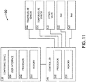
- the system may include at least one computing device 138, at least one controller 146, at least one temperature sensor 152, at least one bypass valve 132, and/or at least one fan (e.g., fan 120 and/or 124), some or all of which may be communicatively coupled at any given time.
- the at least one computing device 138 and the at least one controller 146 may be implemented as a single computing device or as any number of computing devices.
- the at least one temperature sensor 152 may be configured to detect at least one air temperature of at least one of: the standard unit meal box compartment 104, the supply air ducting 112, and/or the return air ducting 116.
- the computing device 138 may include at least one user interface 138, at least one processor 142, and/or at least one memory 144, some or all of which may be communicatively (e.g., wirelessly) coupled at any given time.
- the at least one user interface 138 may be implemented as any suitable user interface(s), such as a display(s) (e.g., a touchscreen display), button(s), a voice recognition system, an eye tracking system, a keyboard, a mouse, and/or the like.
- the at least one user-interface 138 may be configured to present information (e.g., a power status (e.g., on or off) of the air chiller 110 (or its components) and/or a temperature) of one or more of the standard unit meal box compartments 104.
- the at least one user-interface 138 may be configured to interface with a user and receive user inputs, which, for example, may include instructions to change a power status (e.g., on or off) of the air chiller 110 (or its components) and/or a temperature of one or more of the standard unit meal box compartments 104.
- the at least one user-interface 138 may be configured to output the user inputs to the processor 142.
- the processor 142 may be configured to perform any or all of the operations disclosed throughout.
- the computing device 142 may be implemented as any suitable computing device.
- the processor 142 may be configured to run various software applications or computer code stored (e.g., maintained) in a non-transitory computer-readable medium (e.g., memory 144) and configured to execute various instructions or operations.
- the processor 142 may be configured to receive user inputs from the user interface 140. Based on the user inputs, the processor 142 may be configured to determine any operational changes (e.g., to change a power status (e.g., on or off) of the air chiller 110 (or its components) and/or a temperature of one or more of the standard unit meal box compartments 104) to be made to the air chiller 110.
- the processor 142 may be configured to output instructions to the controller 146 to perform the operational changes.
- the controller 146 may include at least one processor 148 and at least one memory 150, which may be communicatively coupled.
- the processor 148 may be implemented as any suitable processor, such as a general purpose processor or a field-programmable gate array (FPGA).
- the processor 148 may be configured to run various software applications or computer code stored (e.g., maintained) in a non-transitory computer-readable medium (e.g., memory 150) and configured to execute various instructions or operations.
- the processor 148 may be implemented as a special purpose processor configured (e.g., programmed) to execute instructions for performing any or all of the operations disclosed throughout.
- the processor 148 may be configured to control operation of the air chiller 110 and/or components of the air chiller 110.
- the processor 148 may be configured to change a power status (e.g., on or off) of the air chiller 110 (or its components) and/or a change a temperature of one or more of the standard unit meal box compartments 104.
- the processor 148 may be configured to control operation of the at least one fan (e.g., 120 and/or 124) based at least on the at least one detected temperature of the at least one temperature sensor 152.
- the processor 148 may be configured to control operation of the bypass valve 132 based at least on the at least one detected temperature of the at least one temperature sensor 152.
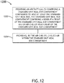
- an exemplary embodiment of a method 1200 may include one or more of the following steps. Additionally, for example, some embodiments may include performing one or more instances of the method 1200 iteratively, concurrently, non-sequentially, and/or sequentially.
- a step 1202 may include providing an aircraft galley comprising a standard unit meal box compartment configured to hold at least one standard unit meal box, the standard unit meal box compartment comprising a door at a front of the standard unit meal box compartment and an air chiller near a rear of the standard unit meal box compartment.
- a step 1204 may include providing, by the air chiller, chilled air within the standard unit meal box compartment.
- method 1200 may include any of the operations disclosed throughout.
- embodiments of the inventive concepts disclosed herein may be directed to a method and a system configured to provide chilled air within a standard unit meal box compartment.
- At least one non-transitory computer-readable medium may refer to as at least one non-transitory computer-readable medium (e.g., memory, storage, or a combination thereof; e.g., at least one computer-readable medium implemented as hardware; e.g., at least one non-transitory processor-readable medium, at least one memory (e.g., at least one nonvolatile memory, at least one volatile memory, or a combination thereof; e.g., at least one random-access memory, at least one flash memory, at least one read-only memory (ROM) (e.g., at least one electrically erasable programmable read-only memory (EEPROM)), at least one on-processor memory (e.g., at least one on-processor cache, at least one on-processor buffer, at least one on-processor flash memory, at least one on-processor EEPROM, or a combination thereof), or a combination thereof), at least one storage device
- At least one means one or a plurality of; for example, “at least one” may comprise one, two, three, ..., one hundred, or more.
- one or more means one or a plurality of; for example, “one or more” may comprise one, two, three, ..., one hundred, or more.
- zero or more means zero, one, or a plurality of; for example, “zero or more” may comprise zero, one, two, three, ..., one hundred, or more.
- the methods, operations, and/or functionality disclosed may be implemented as sets of instructions or software readable by a device. Further, it is understood that the specific order or hierarchy of steps in the methods, operations, and/or functionality disclosed are examples of exemplary approaches. Based upon design preferences, it is understood that the specific order or hierarchy of steps in the methods, operations, and/or functionality can be rearranged while remaining within the scope of the inventive concepts disclosed herein.
- the accompanying claims may present elements of the various steps in a sample order, and are not necessarily meant to be limited to the specific order or hierarchy presented.
- embodiments of the methods according to the inventive concepts disclosed herein may include one or more of the steps described herein. Further, such steps may be carried out in any desired order and two or more of the steps may be carried out simultaneously with one another. Two or more of the steps disclosed herein may be combined in a single step, and in some embodiments, one or more of the steps may be carried out as two or more sub-steps. Further, other steps or sub-steps may be carried in addition to, or as substitutes to one or more of the steps disclosed herein.
- inventive concepts disclosed herein are well adapted to carry out the objects and to attain the advantages mentioned herein as well as those inherent in the inventive concepts disclosed herein. While presently preferred embodiments of the inventive concepts disclosed herein have been described for purposes of this disclosure, it will be understood that numerous changes may be made which will readily suggest themselves to those skilled in the art and which are accomplished within the broad scope and coverage of the inventive concepts disclosed and claimed herein.
Landscapes
- Engineering & Computer Science (AREA)
- Aviation & Aerospace Engineering (AREA)
- Life Sciences & Earth Sciences (AREA)
- Sustainable Development (AREA)
- Devices That Are Associated With Refrigeration Equipment (AREA)
- Cold Air Circulating Systems And Constructional Details In Refrigerators (AREA)
Abstract
Description
- On current aircraft galleys, standard unit meal boxes are used to transport perishable food and beverages. Typically, the compartments, where the standard unit meal boxes are stowed, are unchilled, which limits the types of fresh food that may be carried without the risk of the fresh food spoiling and posing a health risk on long haul flights.
- In one aspect, embodiments of the inventive concepts disclosed herein are directed to a system. The system may include an aircraft galley, which may include a standard unit meal box compartment configured to hold a standard unit meal box. The standard unit meal box compartment may include a door at a front of the standard unit meal box compartment and an air chiller near a rear of the standard unit meal box compartment. The air chiller may be configured to provide chilled air within the standard unit meal box compartment.
- In a further aspect, embodiments of the inventive concepts disclosed herein are directed to a method. The method may include providing an aircraft galley comprising a standard unit meal box compartment configured to hold at least one standard unit meal box, the standard unit meal box compartment comprising a door at a front of the standard unit meal box compartment and an air chiller near a rear of the standard unit meal box compartment. The method may further include providing, by the air chiller, chilled air within the standard unit meal box compartment.
- Implementations of the inventive concepts disclosed herein may be better understood when consideration is given to the following detailed description thereof. Such description makes reference to the included drawings, which are not necessarily to scale, and in which some features may be exaggerated and some features may be omitted or may be represented schematically in the interest of clarity. Like reference numerals in the drawings may represent and refer to the same or similar element, feature, or function. In the drawings:
-
FIG. 1 is a view of an exemplary embodiment of a system including a galley according to the inventive concepts disclosed herein. -
FIG. 2 is a view of an exemplary embodiment of a system including a galley according to the inventive concepts disclosed herein. -
FIG. 3 is a view of an exemplary embodiment of a system including a galley according to the inventive concepts disclosed herein. -
FIGS. 4 ,5, 6, and 7 are views of an exemplary standard unit meal box according to the inventive concepts disclosed herein. -
FIG. 8 is a view of standard unit meal box compartments including a chilled air system of some embodiments according to the inventive concepts disclosed herein. -
FIG. 9 is an exemplary view of the chilled air system ofFIG. 8 of some embodiments according to the inventive concepts disclosed herein. -
FIG. 10 is an exemplary view of the air chiller ofFIGS. 8-9 of some embodiments according to the inventive concepts disclosed herein. -
FIG. 11 is an exemplary view of a system including an aircraft including a galley of some embodiments according to the inventive concepts disclosed herein. -
FIG. 12 is a diagram of an exemplary embodiment of a method according to the inventive concepts disclosed herein. -
FIG. 13 is a view of a standard unit meal box compartment including rub strips and holding a standard unit meal box of some embodiments according to the inventive concepts disclosed herein. - Before explaining at least one embodiment of the inventive concepts disclosed herein in detail, it is to be understood that the inventive concepts are not limited in their application to the details of construction and the arrangement of the components or steps or methodologies set forth in the following description or illustrated in the drawings. In the following detailed description of embodiments of the instant inventive concepts, numerous specific details are set forth in order to provide a more thorough understanding of the inventive concepts. However, it will be apparent to one of ordinary skill in the art having the benefit of the instant disclosure that the inventive concepts disclosed herein may be practiced without these specific details. In other instances, well-known features may not be described in detail to avoid unnecessarily complicating the instant disclosure. The inventive concepts disclosed herein are capable of other embodiments or of being practiced or carried out in various ways. Also, it is to be understood that the phraseology and terminology employed herein is for the purpose of description and should not be regarded as limiting.
- As used herein a letter following a reference numeral is intended to reference an embodiment of the feature or element that may be similar, but not necessarily identical, to a previously described element or feature bearing the same reference numeral (e.g., 1, 1a, 1b). Such shorthand notations are used for purposes of convenience only, and should not be construed to limit the inventive concepts disclosed herein in any way unless expressly stated to the contrary.
- Further, unless expressly stated to the contrary, "or" refers to an inclusive or and not to an exclusive or. For example, a condition A or B is satisfied by anyone of the following: A is true (or present) and B is false (or not present), A is false (or not present) and B is true (or present), and both A and B are true (or present).
- In addition, use of the "a" or "an" are employed to describe elements and components of embodiments of the instant inventive concepts. This is done merely for convenience and to give a general sense of the inventive concepts, and "a" and "an" are intended to include one or at least one and the singular also includes the plural unless it is obvious that it is meant otherwise.
- Finally, as used herein any reference to "one embodiment," or "some embodiments" means that a particular element, feature, structure, or characteristic described in connection with the embodiment is included in at least one embodiment of the inventive concepts disclosed herein. The appearances of the phrase "in some embodiments" in various places in the specification are not necessarily all referring to the same embodiment, and embodiments of the inventive concepts disclosed may include one or more of the features expressly described or inherently present herein, or any combination of sub-combination of two or more such features, along with any other features which may not necessarily be expressly described or inherently present in the instant disclosure.
- Broadly, embodiments of the inventive concepts disclosed herein are directed to a method and a system configured to provide chilled air within a standard unit meal box compartment. Some embodiments may include a standard unit meal box compartment including an air chiller that would provide an environment to preserve high-risk perishable foods. Some embodiments may allow for a greater volume of fresh produce to be carried on an aircraft galley for a longer period of time and/or may provide a means of chilling additional beverages without adding an additional galley insert (GAIN) refrigerator.
- Referring now to
FIGS. 1-3 , exemplary embodiments of a system including a vehicle (e.g., an automobile, a train, a watercraft, a submarine, an aircraft 100) including at least onegalley 102 are depicted according to the inventive concepts. For example, theaircraft 100 may include thegalley 102. Thegalley 102 may include standard unitmeal box compartments 104. Each of the standard unitmeal box compartments 104 may include a rear wall, side walls, and adoor 106 at a front of each standard unitmeal box compartment 104. Each of the standard unitmeal box compartments 104 may be configured to hold at least one standardunit meal box 108. In some embodiments, the standard unitmeal box compartments 104 may include at least one chilled air system, such as shown in and described with respect toFIGS. 8-11 . - For example, as shown in
FIG. 2 , each of the standard unitmeal box compartments 104 may be configured to hold at least one standardunit meal box 108. The standard unitmeal box compartments 104 may include single width double depth standard unitmeal box compartments 104A configured to hold two standardunit meal boxes 108. The standard unitmeal box compartments 104 may include single width single depth standard unitmeal box compartments 104B configured to hold one standardunit meal box 108. The standard unitmeal box compartments 104 may include double width double depth standard unitmeal box compartments 104C configured to hold four standardunit meal boxes 108. - Referring now to
FIGS. 4-7 , views of a standardunit meal box 108 of some embodiments according to the inventive concepts disclosed herein are depicted.FIG. 4 shows an isometric view of the standardunit meal box 108.FIG. 5 shows a side view of the standardunit meal box 108.FIG. 6 shows a front view of the standardunit meal box 108.FIG. 7 shows a top view of the standardunit meal box 108. In some embodiments, the standardunit meal box 108 may have approximate (e.g., +/- 10%) dimensions of 394 millimeters (mm) by 279 mm by 288 mm. The standardunit meal box 108 may include handles on the top and front of the standardunit meal box 108. The standardunit meal box 108 may be placed within the standard unitmeal box compartment 104. Typically, the standardunit meal box 108 may be a reinforced aluminum metal container with a door at one end for transporting food on theaircraft 100. For example, the standardunit meal box 108 may be an ATLAS standard, standard unit meal box. The standardunit meal box 108 may be designed to fit in the standard unit meal box compartment 104 (e.g., a standard ARINC standard unit compartment) ingalleys 102. For example, the standardunit meal box 108 may be approximately 25 - 30 mm less in width and height than a single width standard unitmeal box compartment 104. The space between the inner walls of the standard unitmeal box compartment 104 and the outer walls of the standardunit meal box 108 may be used to circulate chilled air around the standardunit meal box 108 and within the standard unitmeal box compartment 104 to chill the standardunit meal box 108. The standard unit meal box compartments 104 may have rub strips 154 (e.g., plastic rub strips) on four sides (e.g., top, bottom, and two side walls), such as shown inFIG. 13 . The rub strips 154 may be 8 - 10 mm in depth and may be installed in pairs on the top and bottom of the standard unit meal box compartments 104. - Referring now to
FIG. 8 , a view of standard unit meal box compartments 104 including a chilled air system of some embodiments according to the inventive concepts disclosed herein is depicted. For example, one, some, or all of the standard unit meal box compartments 104 may include anair chiller 110 near (e.g., at) a rear of a particular standard unitmeal box compartment 104, and theair chiller 110 may be configured to provide chilled air within one, some, or all of the standard unit meal box compartments 104. For example, theair chiller 110 may be positioned at a bottom rear corner of the standard unitmeal box compartment 104. In some embodiments, each standard unitmeal box compartment 104 includes anair chiller 110. - For example, as shown in
FIG. 8 ,supply air ducting 112 and returnair ducting 116 may be installed within one, some, or all of the standard unit meal box compartments 104. Thesupply air ducting 112 and thereturn air ducting 116 may be installed in unused space behind the standardunit meal box 108, when the standardunit meal box 108 is placed within the standard unitmeal box compartment 104. Chilled air may be supplied to one, some, or all of the standard unit meal box compartments 104 from theair chiller 110 via thesupply air ducting 112. Return air may be returned from one, some, or all of the standard unit meal box compartments 104 to theair chiller 110 via thereturn air ducting 116. For example, thesupply air ducting 112 and thereturn air ducting 116 may extend from one standard unitmeal box compartment 104 to a second standard unitmeal box compartment 104. For example, each of the standard unit meal box compartments 104 may include asupply air outlet 114 and areturn air inlet 118. Thesupply air outlet 114 may be coupled to thesupply air ducting 112, and thereturn air inlet 118 may be coupled to thereturn air ducting 116. In some embodiments, thesupply air outlets 114 may be located at tops of the standard unit meal box compartments 104, and thereturn air inlets 118 may be located at bottoms of the standard unit meal box compartments 104. For example, as shown inFIG. 13 , each returnair inlet 118 and eachsupply air outlet 114 may have a width greater than a height and may be positioned between a pair of rub strips 154 such that chilled air flows from thesupply air outlet 114 above the standardunit meal box 108 toward the front of the standard unitmeal box compartment 104 and is returned from the front of the standard unitmeal box compartment 104 under the standardunit meal box 108 to thereturn air inlet 118. As shown inFIG. 8 , asingle air chiller 110 may provide chilled air to two or more standard unit meal box compartments 104; however, in some embodiments, each standard unitmeal box compartment 104 may include anair chiller 110. In some embodiments, theair chiller 110 may be installed in unused space behind the standardunit meal box 108, when the standardunit meal box 108 is placed within the standard unitmeal box compartment 104. In some embodiments, theair chiller 110 may be installed outside of the standard unitmeal box compartment 104, such as on the galley roof or on the back wall behind the standard unit meal box compartments 104. - Referring now to
FIG. 9 , an exemplary view of the chilled air system ofFIG. 8 of some embodiments according to the inventive concepts disclosed herein is depicted. The chilled air system may include the air chiller 110 (as shown by a side partial see-through view) and aliquid chiller 126. - The
air chiller 110 may include at least one fan (e.g.,fan 120 and/or fan 124), at least oneheat exchanger 122, chilled liquid lines 128 (e.g., chilled liquid supply and return lines), connectors 130 (e.g., quick disconnectors), abypass valve 132, at least onebaffle 134, and/or acondensate drain 136. In some embodiments, theair chiller 110 may have dimensions of less than 8 inches (20.32 cm) by less than 6 inches (15.24 cm) by less than 5 inches (12.7 cm) (e.g., 7 inches (17.78 cm) by 5 inches (12.7 cm) by 4 inches 10.16 cm)). - The chilled liquid supply line may provide chilled liquid to the
heat exchanger 122, and the chilled liquid return line may return chilled liquid from theheat exchanger 122 to theliquid chiller 126. In some embodiments, the chilled liquid may be propylene glycol water (PGW). Theliquid chiller 126 may be coupled to the chilled liquid supply line and the chilled liquid return line. In some embodiments, theliquid chiller 126 may be installed outside of the standard unitmeal box compartment 104; however, in some embodiments, theliquid chiller 126 may be installed in the standard unitmeal box compartment 104. - The
bypass valve 132 may be coupled to the chilled liquid supply line. In some embodiments, thebypass valve 132 may be a liquid proportioning bypass valve. When activated, thebypass valve 132 may be configured to direct (e.g., in part or in whole) a flow of the chilled liquid to bypass theheat exchanger 122. In some embodiments, a controller (e.g., 146) may be configured to control operation of thebypass valve 132 based at least on at least one detected temperature of at least one temperature sensor (e.g., 152). - The at least one fan (e.g., 120 and/or 124) may be configured to pull return air from the
return air ducting 116. The at least one fan (e.g., 120 and/or 124) may be further configured to at least one of blow or pull air over theheat exchanger 122 causing the air to be chilled as chilled air. The at least one fan (e.g., 120 and/or 124) may be further configured to blow the chilled air out of theair chiller 110 into thesupply air ducting 112. Some embodiments may include twoaxial fans - Referring now to
FIG. 10 , a view of the air inlet side of theair chiller 110 ofFIGS. 8-9 of some embodiments according to the inventive concepts disclosed herein is depicted. - Referring now to
FIG. 11 , an exemplary embodiment of a system including theaircraft 100 including the at least onegalley 102 is depicted according to the inventive concepts. The system may include at least onecomputing device 138, at least onecontroller 146, at least onetemperature sensor 152, at least onebypass valve 132, and/or at least one fan (e.g.,fan 120 and/or 124), some or all of which may be communicatively coupled at any given time. In some embodiments, the at least onecomputing device 138 and the at least onecontroller 146 may be implemented as a single computing device or as any number of computing devices. - The at least one
temperature sensor 152 may be configured to detect at least one air temperature of at least one of: the standard unitmeal box compartment 104, thesupply air ducting 112, and/or thereturn air ducting 116. - The
computing device 138 may include at least oneuser interface 138, at least oneprocessor 142, and/or at least onememory 144, some or all of which may be communicatively (e.g., wirelessly) coupled at any given time. - The at least one
user interface 138 may be implemented as any suitable user interface(s), such as a display(s) (e.g., a touchscreen display), button(s), a voice recognition system, an eye tracking system, a keyboard, a mouse, and/or the like. For example, the at least one user-interface 138 may be configured to present information (e.g., a power status (e.g., on or off) of the air chiller 110 (or its components) and/or a temperature) of one or more of the standard unit meal box compartments 104. For example, the at least one user-interface 138 may be configured to interface with a user and receive user inputs, which, for example, may include instructions to change a power status (e.g., on or off) of the air chiller 110 (or its components) and/or a temperature of one or more of the standard unit meal box compartments 104. For example, the at least one user-interface 138 may be configured to output the user inputs to theprocessor 142. - The
processor 142 may be configured to perform any or all of the operations disclosed throughout. Thecomputing device 142 may be implemented as any suitable computing device. Theprocessor 142 may be configured to run various software applications or computer code stored (e.g., maintained) in a non-transitory computer-readable medium (e.g., memory 144) and configured to execute various instructions or operations. For example, theprocessor 142 may be configured to receive user inputs from theuser interface 140. Based on the user inputs, theprocessor 142 may be configured to determine any operational changes (e.g., to change a power status (e.g., on or off) of the air chiller 110 (or its components) and/or a temperature of one or more of the standard unit meal box compartments 104) to be made to theair chiller 110. Theprocessor 142 may be configured to output instructions to thecontroller 146 to perform the operational changes. - The
controller 146 may include at least oneprocessor 148 and at least onememory 150, which may be communicatively coupled. Theprocessor 148 may be implemented as any suitable processor, such as a general purpose processor or a field-programmable gate array (FPGA). Theprocessor 148 may be configured to run various software applications or computer code stored (e.g., maintained) in a non-transitory computer-readable medium (e.g., memory 150) and configured to execute various instructions or operations. Theprocessor 148 may be implemented as a special purpose processor configured (e.g., programmed) to execute instructions for performing any or all of the operations disclosed throughout. - For example, the
processor 148 may be configured to control operation of theair chiller 110 and/or components of theair chiller 110. For example, theprocessor 148 may be configured to change a power status (e.g., on or off) of the air chiller 110 (or its components) and/or a change a temperature of one or more of the standard unit meal box compartments 104. For example, theprocessor 148 may be configured to control operation of the at least one fan (e.g., 120 and/or 124) based at least on the at least one detected temperature of the at least onetemperature sensor 152. For example, theprocessor 148 may be configured to control operation of thebypass valve 132 based at least on the at least one detected temperature of the at least onetemperature sensor 152. - Referring now to
FIG. 12 , an exemplary embodiment of amethod 1200 according to the inventive concepts disclosed herein may include one or more of the following steps. Additionally, for example, some embodiments may include performing one or more instances of themethod 1200 iteratively, concurrently, non-sequentially, and/or sequentially. - A
step 1202 may include providing an aircraft galley comprising a standard unit meal box compartment configured to hold at least one standard unit meal box, the standard unit meal box compartment comprising a door at a front of the standard unit meal box compartment and an air chiller near a rear of the standard unit meal box compartment. - A
step 1204 may include providing, by the air chiller, chilled air within the standard unit meal box compartment. - Further, the
method 1200 may include any of the operations disclosed throughout. - As will be appreciated from the above, embodiments of the inventive concepts disclosed herein may be directed to a method and a system configured to provide chilled air within a standard unit meal box compartment.
- As used throughout and as would be appreciated by those skilled in the art, "at least one non-transitory computer-readable medium" may refer to as at least one non-transitory computer-readable medium (e.g., memory, storage, or a combination thereof; e.g., at least one computer-readable medium implemented as hardware; e.g., at least one non-transitory processor-readable medium, at least one memory (e.g., at least one nonvolatile memory, at least one volatile memory, or a combination thereof; e.g., at least one random-access memory, at least one flash memory, at least one read-only memory (ROM) (e.g., at least one electrically erasable programmable read-only memory (EEPROM)), at least one on-processor memory (e.g., at least one on-processor cache, at least one on-processor buffer, at least one on-processor flash memory, at least one on-processor EEPROM, or a combination thereof), or a combination thereof), at least one storage device (e.g., at least one hard-disk drive, at least one tape drive, at least one solid-state drive, at least one flash drive, at least one readable and/or writable disk of at least one optical drive configured to read from and/or write to the at least one readable and/or writable disk, or a combination thereof), or a combination thereof).
- As used throughout, "at least one" means one or a plurality of; for example, "at least one" may comprise one, two, three, ..., one hundred, or more. Similarly, as used throughout, "one or more" means one or a plurality of; for example, "one or more" may comprise one, two, three, ..., one hundred, or more. Further, as used throughout, "zero or more" means zero, one, or a plurality of; for example, "zero or more" may comprise zero, one, two, three, ..., one hundred, or more.
- In the present disclosure, the methods, operations, and/or functionality disclosed may be implemented as sets of instructions or software readable by a device. Further, it is understood that the specific order or hierarchy of steps in the methods, operations, and/or functionality disclosed are examples of exemplary approaches. Based upon design preferences, it is understood that the specific order or hierarchy of steps in the methods, operations, and/or functionality can be rearranged while remaining within the scope of the inventive concepts disclosed herein. The accompanying claims may present elements of the various steps in a sample order, and are not necessarily meant to be limited to the specific order or hierarchy presented.
- It is to be understood that embodiments of the methods according to the inventive concepts disclosed herein may include one or more of the steps described herein. Further, such steps may be carried out in any desired order and two or more of the steps may be carried out simultaneously with one another. Two or more of the steps disclosed herein may be combined in a single step, and in some embodiments, one or more of the steps may be carried out as two or more sub-steps. Further, other steps or sub-steps may be carried in addition to, or as substitutes to one or more of the steps disclosed herein.
- From the above description, it is clear that the inventive concepts disclosed herein are well adapted to carry out the objects and to attain the advantages mentioned herein as well as those inherent in the inventive concepts disclosed herein. While presently preferred embodiments of the inventive concepts disclosed herein have been described for purposes of this disclosure, it will be understood that numerous changes may be made which will readily suggest themselves to those skilled in the art and which are accomplished within the broad scope and coverage of the inventive concepts disclosed and claimed herein.
Claims (15)
- A system, comprising:
an aircraft galley (102), comprising:
a standard unit meal box compartment (104) configured to hold at least one standard unit meal box (108), the standard unit meal box compartment comprising:a door (106) at a front of the standard unit meal box compartment; andan air chiller (110) near a rear of the standard unit meal box compartment, the air chiller configured to provide chilled air within the standard unit meal box compartment. - The system of claim 1, wherein the air chiller (110) has dimensions of less than 8 inches (20.32 cm) by less than 6 inches (15.24 cm) by less than 5 inches (12.7 cm).
- The system of claim 1 or 2, wherein the standard unit meal box compartment further comprises supply air ducting (112) and return air ducting (116), wherein chilled air is supplied to the standard unit meal box compartment from the air chiller via the supply air ducting, wherein return air is returned from the standard unit meal box compartment to the air chiller via the return air ducting.
- The system of claim 3, wherein the standard unit meal box compartment further comprises a supply air outlet (114) and a return air inlet (118), the supply air outlet coupled to the supply air ducting, the return air inlet coupled to the return air ducting.
- The system of claim 4, wherein the supply air outlet is at a top of the standard unit meal box compartment, wherein the return air inlet is at a bottom of the standard unit meal box compartment wherein the supply air outlet is positioned between a first pair of rub strips, wherein the return air inlet is positioned between a second pair of rub strips.
- The system of claim 4, wherein the aircraft galley further comprises a second standard unit meal box compartment, wherein the supply air ducting and the return air ducting extends from the standard unit meal box compartment to the second standard unit meal box compartment, wherein the second standard unit meal box compartment comprises a second supply air outlet and a second return air inlet, the second supply air outlet coupled to the supply air ducting, the second return air inlet coupled to the return air ducting, wherein the air chiller is further configured to provide chilled air within the standard unit meal box compartment and the second standard unit meal box compartment.
- The system of any preceding claim, wherein the air chiller comprises at least one fan (120, 124), a heat exchanger (122), a chilled liquid supply line (128), and a chilled liquid return line, wherein the chilled liquid supply line provides chilled liquid to the heat exchanger, wherein the at least one fan is configured to at least one of blow or pull air over the heat exchanger causing the air to be chilled as the chilled air, wherein the at least one fan is further configured to blow the chilled air out of the air chiller.
- The system of claim 7, wherein the at least one fan is two fans (120, 124).
- The system of claim 7, wherein the at least one fan is at least one axial fan.
- The system of claim 7, 8 or 9, further comprising a liquid chiller (126) coupled to the chilled liquid supply line and the chilled liquid return line, the liquid chiller configured to supply the chilled liquid to the chilled liquid supply line and receive returned chilled liquid from the chilled liquid return line.
- The system of claim 7, 8, 9 or 10, further comprising a controller (146) configured to control operation of the air chiller.
- The system of claim 11, wherein the standard unit meal box compartment further comprises at least one temperature sensor (152) configured to detect at least one temperature of at least one of the standard unit meal box compartment, supply air ducting, or return air ducting.
- The system of claim 12, wherein the controller is further configured to control operation of the at least one fan based at least on the at least one detected temperature of the at least one temperature sensor.
- The system of claim 12 or 13, wherein the air chiller further comprises a bypass valve (132) coupled to the chilled liquid supply line, when activated the bypass valve being configured to direct a flow of the chilled liquid to bypass the heat exchanger, wherein the controller is further configured to control operation of the bypass valve based at least on the at least one detected temperature of the at least one temperature sensor.
- A method, comprising:providing an aircraft galley (102) comprising a standard unit meal box compartment (104) configured to hold at least one standard unit meal box (108), the standard unit meal box compartment comprising a door at a front of the standard unit meal box compartment and an air chiller (110) near a rear of the standard unit meal box compartment;providing, by the air chiller, chilled air within the standard unit meal box compartment.
Applications Claiming Priority (1)
| Application Number | Priority Date | Filing Date | Title |
|---|---|---|---|
| US16/681,179 US11286049B2 (en) | 2019-11-12 | 2019-11-12 | Standard unit meal box compartment including air chiller |
Publications (2)
| Publication Number | Publication Date |
|---|---|
| EP3822165A1 true EP3822165A1 (en) | 2021-05-19 |
| EP3822165B1 EP3822165B1 (en) | 2024-06-19 |
Family
ID=73401457
Family Applications (1)
| Application Number | Title | Priority Date | Filing Date |
|---|---|---|---|
| EP20207307.8A Active EP3822165B1 (en) | 2019-11-12 | 2020-11-12 | Standard unit meal box compartment including air chiller |
Country Status (3)
| Country | Link |
|---|---|
| US (1) | US11286049B2 (en) |
| EP (1) | EP3822165B1 (en) |
| CN (1) | CN112841929B (en) |
Families Citing this family (1)
| Publication number | Priority date | Publication date | Assignee | Title |
|---|---|---|---|---|
| US12130069B2 (en) * | 2022-08-23 | 2024-10-29 | Peter Berkeley | Vehicle refrigeration system for food carts |
Citations (3)
| Publication number | Priority date | Publication date | Assignee | Title |
|---|---|---|---|---|
| US20100224726A1 (en) * | 2009-03-04 | 2010-09-09 | B/E Aerospace, Inc. | Wall-mounted point-of-use air chiller for aircraft galley cart compartment |
| WO2013149143A1 (en) * | 2012-03-30 | 2013-10-03 | B/E Aerospace, Inc. B/E Aerospace, Inc. | Aircraft galley chiller system |
| US20170122647A1 (en) * | 2014-07-08 | 2017-05-04 | B/E Aerospace, Inc. | Compact liquid cooled, air through galley chiller |
Family Cites Families (30)
| Publication number | Priority date | Publication date | Assignee | Title |
|---|---|---|---|---|
| US4784054A (en) * | 1986-08-28 | 1988-11-15 | Restaurant Technology, Inc. | Equipment for holding or staging packaged sandwiches |
| SE0302000D0 (en) * | 2003-07-04 | 2003-07-04 | Electrolux Home Prod Corp | Cabinet refrigeration system |
| JP2005134002A (en) | 2003-10-29 | 2005-05-26 | Jamco Corp | Air chiller device |
| JP2005134001A (en) | 2003-10-29 | 2005-05-26 | Jamco Corp | Air chiller device |
| JP2005164093A (en) | 2003-12-01 | 2005-06-23 | Jamco Corp | Air chiller device |
| JP4200084B2 (en) | 2003-12-01 | 2008-12-24 | 株式会社ジャムコ | Air chiller device |
| US7231778B2 (en) | 2004-03-29 | 2007-06-19 | Be Intellectual Property, Inc. | Cooling system for a commercial aircraft galley |
| JP4291730B2 (en) | 2004-04-26 | 2009-07-08 | 株式会社ジャムコ | Air chiller device |
| DE102006005035B3 (en) | 2006-02-03 | 2007-09-27 | Airbus Deutschland Gmbh | cooling system |
| US7954761B2 (en) * | 2006-11-30 | 2011-06-07 | Be Aerospace, Inc. | Modular integrated galley |
| US8056349B2 (en) * | 2007-08-13 | 2011-11-15 | B/E Aerospace, Inc. | Method and apparatus for maintaining a uniform temperature in a refrigeration system |
| CN101469931B (en) * | 2008-06-12 | 2010-06-16 | 吴速 | Air conditioner, refrigerator and water heater integrated machine |
| GB2466990A (en) * | 2009-01-19 | 2010-07-21 | Kenneth Thomas Stewart | Refrigerated food storage unit with a baffle plate to disperse air flow evenly across a chilling unit |
| FR2964085B1 (en) * | 2010-08-24 | 2013-08-23 | Airbus Operations Sas | AUTOMATED FURNITURE STORAGE OF CARTS AND AIRCRAFT INCORPORATING SUCH A FURNITURE |
| US9188380B2 (en) * | 2011-08-23 | 2015-11-17 | B/E Aerospace, Inc. | Aircraft galley liquid cooling system |
| WO2013033439A1 (en) * | 2011-08-30 | 2013-03-07 | B/E Aerospace, Inc. | Reconfigurable chilled air outlet for an aircraft galley chiller |
| CN106949695A (en) | 2012-03-22 | 2017-07-14 | B/E航空公司 | Vehicles refrigeration plant with steam circulation |
| US9359078B2 (en) * | 2012-03-28 | 2016-06-07 | B/E Aerospace, Inc. | Aircraft galley monument structure |
| US10124894B2 (en) * | 2012-03-30 | 2018-11-13 | B/E Aerospace, Inc. | Aircraft galley chilled air distribution system |
| CN102620502A (en) * | 2012-04-17 | 2012-08-01 | 合肥美菱股份有限公司 | Refrigeration module for refrigerators |
| US20130344789A1 (en) * | 2012-05-03 | 2013-12-26 | Thomas M. Lee | Remote heated and cooled compartments for aircraft galleys |
| US9676483B2 (en) | 2013-07-03 | 2017-06-13 | B/E Aerospace, Inc. | Aircraft galley air chiller system |
| EP3097015B1 (en) * | 2014-01-20 | 2021-08-11 | Safran Cabin Catering B.V. | A galley container and a cooling element to cool the interior of the galley container |
| JP6419837B2 (en) | 2014-03-24 | 2018-11-07 | ビーイー・エアロスペース・インコーポレーテッドB/E Aerospace, Inc. | Moving body cooling apparatus having liquid heat exhaust system |
| US9957050B2 (en) * | 2015-05-19 | 2018-05-01 | The Boeing Company | Galley cart and galley system of an aircraft |
| DE102016125562A1 (en) * | 2016-12-23 | 2018-06-28 | Airbus Operations Gmbh | Aircraft galley |
| DE102017200734A1 (en) * | 2017-01-18 | 2018-07-19 | Airbus Operations Gmbh | Temperature control system for a Galleyfach a galley |
| CA2976367C (en) * | 2017-08-11 | 2020-05-12 | Paul HASTINGS | Patty vending machine |
| DE102017130722A1 (en) * | 2017-12-20 | 2019-06-27 | Airbus Operations Gmbh | Aircraft galley |
| CN108438233B (en) * | 2018-05-04 | 2023-07-11 | 南京航空航天大学 | Helicopter air conditioning system |
-
2019
- 2019-11-12 US US16/681,179 patent/US11286049B2/en active Active
-
2020
- 2020-11-12 EP EP20207307.8A patent/EP3822165B1/en active Active
- 2020-11-12 CN CN202011262970.0A patent/CN112841929B/en active Active
Patent Citations (3)
| Publication number | Priority date | Publication date | Assignee | Title |
|---|---|---|---|---|
| US20100224726A1 (en) * | 2009-03-04 | 2010-09-09 | B/E Aerospace, Inc. | Wall-mounted point-of-use air chiller for aircraft galley cart compartment |
| WO2013149143A1 (en) * | 2012-03-30 | 2013-10-03 | B/E Aerospace, Inc. B/E Aerospace, Inc. | Aircraft galley chiller system |
| US20170122647A1 (en) * | 2014-07-08 | 2017-05-04 | B/E Aerospace, Inc. | Compact liquid cooled, air through galley chiller |
Also Published As
| Publication number | Publication date |
|---|---|
| EP3822165B1 (en) | 2024-06-19 |
| CN112841929B (en) | 2024-04-19 |
| US20210139148A1 (en) | 2021-05-13 |
| US11286049B2 (en) | 2022-03-29 |
| CN112841929A (en) | 2021-05-28 |
Similar Documents
| Publication | Publication Date | Title |
|---|---|---|
| US11440662B2 (en) | Dry ice draw through galley cooling | |
| US11643213B2 (en) | Galley cart and galley system of an aircraft | |
| KR102614663B1 (en) | Galley system of an aircraft | |
| EP3038916B1 (en) | Aircraft galley with air-through carts | |
| US20160338488A1 (en) | Systems and methods of cooling a galley of an aircraft | |
| US20130269384A1 (en) | Aircraft galley chiller system | |
| EP3811008B1 (en) | Refrigerated container provided with ventilation system | |
| US20180037323A1 (en) | Galley compartment for a galley system of an aircraft | |
| EP3822165B1 (en) | Standard unit meal box compartment including air chiller | |
| CN104364593A (en) | Dynamic chilled mini-bar for aircraft passenger suite | |
| US9738389B2 (en) | Systems and methods for cooling using galley monuments | |
| BR102016007170B1 (en) | KITCHEN AND KITCHEN REFRIGERATION SYSTEMS | |
| US11198511B2 (en) | Air supply and return system of a galley of an aircraft | |
| NZ734841B2 (en) | Air supply and return system of a galley of an aircraft | |
| Kokus et al. | Long-term performance of the global air transport system in special consideration of sustainability issues | |
| JP2015155244A (en) | Box-shaped rear deck |
Legal Events
| Date | Code | Title | Description |
|---|---|---|---|
| PUAI | Public reference made under article 153(3) epc to a published international application that has entered the european phase |
Free format text: ORIGINAL CODE: 0009012 |
|
| STAA | Information on the status of an ep patent application or granted ep patent |
Free format text: STATUS: THE APPLICATION HAS BEEN PUBLISHED |
|
| AK | Designated contracting states |
Kind code of ref document: A1 Designated state(s): AL AT BE BG CH CY CZ DE DK EE ES FI FR GB GR HR HU IE IS IT LI LT LU LV MC MK MT NL NO PL PT RO RS SE SI SK SM TR |
|
| STAA | Information on the status of an ep patent application or granted ep patent |
Free format text: STATUS: REQUEST FOR EXAMINATION WAS MADE |
|
| 17P | Request for examination filed |
Effective date: 20211119 |
|
| RBV | Designated contracting states (corrected) |
Designated state(s): AL AT BE BG CH CY CZ DE DK EE ES FI FR GB GR HR HU IE IS IT LI LT LU LV MC MK MT NL NO PL PT RO RS SE SI SK SM TR |
|
| STAA | Information on the status of an ep patent application or granted ep patent |
Free format text: STATUS: EXAMINATION IS IN PROGRESS |
|
| 17Q | First examination report despatched |
Effective date: 20221207 |
|
| P01 | Opt-out of the competence of the unified patent court (upc) registered |
Effective date: 20230922 |
|
| GRAP | Despatch of communication of intention to grant a patent |
Free format text: ORIGINAL CODE: EPIDOSNIGR1 |
|
| STAA | Information on the status of an ep patent application or granted ep patent |
Free format text: STATUS: GRANT OF PATENT IS INTENDED |
|
| RIC1 | Information provided on ipc code assigned before grant |
Ipc: B64D 13/06 20060101ALN20240201BHEP Ipc: B64D 11/04 20060101AFI20240201BHEP |
|
| INTG | Intention to grant announced |
Effective date: 20240216 |
|
| RIC1 | Information provided on ipc code assigned before grant |
Ipc: B64D 13/06 20060101ALN20240202BHEP Ipc: B64D 11/04 20060101AFI20240202BHEP |
|
| GRAS | Grant fee paid |
Free format text: ORIGINAL CODE: EPIDOSNIGR3 |
|
| GRAA | (expected) grant |
Free format text: ORIGINAL CODE: 0009210 |
|
| STAA | Information on the status of an ep patent application or granted ep patent |
Free format text: STATUS: THE PATENT HAS BEEN GRANTED |
|
| AK | Designated contracting states |
Kind code of ref document: B1 Designated state(s): AL AT BE BG CH CY CZ DE DK EE ES FI FR GB GR HR HU IE IS IT LI LT LU LV MC MK MT NL NO PL PT RO RS SE SI SK SM TR |
|
| REG | Reference to a national code |
Ref country code: GB Ref legal event code: FG4D |
|
| REG | Reference to a national code |
Ref country code: CH Ref legal event code: EP |
|
| REG | Reference to a national code |
Ref country code: DE Ref legal event code: R096 Ref document number: 602020032566 Country of ref document: DE |
|
| PG25 | Lapsed in a contracting state [announced via postgrant information from national office to epo] |
Ref country code: BG Free format text: LAPSE BECAUSE OF FAILURE TO SUBMIT A TRANSLATION OF THE DESCRIPTION OR TO PAY THE FEE WITHIN THE PRESCRIBED TIME-LIMIT Effective date: 20240619 |
|
| PG25 | Lapsed in a contracting state [announced via postgrant information from national office to epo] |
Ref country code: FI Free format text: LAPSE BECAUSE OF FAILURE TO SUBMIT A TRANSLATION OF THE DESCRIPTION OR TO PAY THE FEE WITHIN THE PRESCRIBED TIME-LIMIT Effective date: 20240619 Ref country code: HR Free format text: LAPSE BECAUSE OF FAILURE TO SUBMIT A TRANSLATION OF THE DESCRIPTION OR TO PAY THE FEE WITHIN THE PRESCRIBED TIME-LIMIT Effective date: 20240619 |
|
| REG | Reference to a national code |
Ref country code: LT Ref legal event code: MG9D |
|
| PG25 | Lapsed in a contracting state [announced via postgrant information from national office to epo] |
Ref country code: GR Free format text: LAPSE BECAUSE OF FAILURE TO SUBMIT A TRANSLATION OF THE DESCRIPTION OR TO PAY THE FEE WITHIN THE PRESCRIBED TIME-LIMIT Effective date: 20240920 |
|
| REG | Reference to a national code |
Ref country code: NL Ref legal event code: MP Effective date: 20240619 |
|
| PG25 | Lapsed in a contracting state [announced via postgrant information from national office to epo] |
Ref country code: LV Free format text: LAPSE BECAUSE OF FAILURE TO SUBMIT A TRANSLATION OF THE DESCRIPTION OR TO PAY THE FEE WITHIN THE PRESCRIBED TIME-LIMIT Effective date: 20240619 |
|
| PG25 | Lapsed in a contracting state [announced via postgrant information from national office to epo] |
Ref country code: NO Free format text: LAPSE BECAUSE OF FAILURE TO SUBMIT A TRANSLATION OF THE DESCRIPTION OR TO PAY THE FEE WITHIN THE PRESCRIBED TIME-LIMIT Effective date: 20240919 Ref country code: LV Free format text: LAPSE BECAUSE OF FAILURE TO SUBMIT A TRANSLATION OF THE DESCRIPTION OR TO PAY THE FEE WITHIN THE PRESCRIBED TIME-LIMIT Effective date: 20240619 Ref country code: HR Free format text: LAPSE BECAUSE OF FAILURE TO SUBMIT A TRANSLATION OF THE DESCRIPTION OR TO PAY THE FEE WITHIN THE PRESCRIBED TIME-LIMIT Effective date: 20240619 Ref country code: GR Free format text: LAPSE BECAUSE OF FAILURE TO SUBMIT A TRANSLATION OF THE DESCRIPTION OR TO PAY THE FEE WITHIN THE PRESCRIBED TIME-LIMIT Effective date: 20240920 Ref country code: FI Free format text: LAPSE BECAUSE OF FAILURE TO SUBMIT A TRANSLATION OF THE DESCRIPTION OR TO PAY THE FEE WITHIN THE PRESCRIBED TIME-LIMIT Effective date: 20240619 Ref country code: BG Free format text: LAPSE BECAUSE OF FAILURE TO SUBMIT A TRANSLATION OF THE DESCRIPTION OR TO PAY THE FEE WITHIN THE PRESCRIBED TIME-LIMIT Effective date: 20240619 Ref country code: RS Free format text: LAPSE BECAUSE OF FAILURE TO SUBMIT A TRANSLATION OF THE DESCRIPTION OR TO PAY THE FEE WITHIN THE PRESCRIBED TIME-LIMIT Effective date: 20240919 |
|
| PG25 | Lapsed in a contracting state [announced via postgrant information from national office to epo] |
Ref country code: NL Free format text: LAPSE BECAUSE OF FAILURE TO SUBMIT A TRANSLATION OF THE DESCRIPTION OR TO PAY THE FEE WITHIN THE PRESCRIBED TIME-LIMIT Effective date: 20240619 |
|
| REG | Reference to a national code |
Ref country code: AT Ref legal event code: MK05 Ref document number: 1695783 Country of ref document: AT Kind code of ref document: T Effective date: 20240619 |
|
| PG25 | Lapsed in a contracting state [announced via postgrant information from national office to epo] |
Ref country code: NL Free format text: LAPSE BECAUSE OF FAILURE TO SUBMIT A TRANSLATION OF THE DESCRIPTION OR TO PAY THE FEE WITHIN THE PRESCRIBED TIME-LIMIT Effective date: 20240619 |
|
| PG25 | Lapsed in a contracting state [announced via postgrant information from national office to epo] |
Ref country code: PT Free format text: LAPSE BECAUSE OF FAILURE TO SUBMIT A TRANSLATION OF THE DESCRIPTION OR TO PAY THE FEE WITHIN THE PRESCRIBED TIME-LIMIT Effective date: 20241021 |
|
| PG25 | Lapsed in a contracting state [announced via postgrant information from national office to epo] |
Ref country code: PT Free format text: LAPSE BECAUSE OF FAILURE TO SUBMIT A TRANSLATION OF THE DESCRIPTION OR TO PAY THE FEE WITHIN THE PRESCRIBED TIME-LIMIT Effective date: 20241021 |
|
| PG25 | Lapsed in a contracting state [announced via postgrant information from national office to epo] |
Ref country code: PL Free format text: LAPSE BECAUSE OF FAILURE TO SUBMIT A TRANSLATION OF THE DESCRIPTION OR TO PAY THE FEE WITHIN THE PRESCRIBED TIME-LIMIT Effective date: 20240619 |
|
| PG25 | Lapsed in a contracting state [announced via postgrant information from national office to epo] |
Ref country code: EE Free format text: LAPSE BECAUSE OF FAILURE TO SUBMIT A TRANSLATION OF THE DESCRIPTION OR TO PAY THE FEE WITHIN THE PRESCRIBED TIME-LIMIT Effective date: 20240619 |
|
| PG25 | Lapsed in a contracting state [announced via postgrant information from national office to epo] |
Ref country code: IS Free format text: LAPSE BECAUSE OF FAILURE TO SUBMIT A TRANSLATION OF THE DESCRIPTION OR TO PAY THE FEE WITHIN THE PRESCRIBED TIME-LIMIT Effective date: 20241019 Ref country code: AT Free format text: LAPSE BECAUSE OF FAILURE TO SUBMIT A TRANSLATION OF THE DESCRIPTION OR TO PAY THE FEE WITHIN THE PRESCRIBED TIME-LIMIT Effective date: 20240619 |
|
| PG25 | Lapsed in a contracting state [announced via postgrant information from national office to epo] |
Ref country code: CZ Free format text: LAPSE BECAUSE OF FAILURE TO SUBMIT A TRANSLATION OF THE DESCRIPTION OR TO PAY THE FEE WITHIN THE PRESCRIBED TIME-LIMIT Effective date: 20240619 |
|
| PG25 | Lapsed in a contracting state [announced via postgrant information from national office to epo] |
Ref country code: RO Free format text: LAPSE BECAUSE OF FAILURE TO SUBMIT A TRANSLATION OF THE DESCRIPTION OR TO PAY THE FEE WITHIN THE PRESCRIBED TIME-LIMIT Effective date: 20240619 Ref country code: SK Free format text: LAPSE BECAUSE OF FAILURE TO SUBMIT A TRANSLATION OF THE DESCRIPTION OR TO PAY THE FEE WITHIN THE PRESCRIBED TIME-LIMIT Effective date: 20240619 |
|
| PG25 | Lapsed in a contracting state [announced via postgrant information from national office to epo] |
Ref country code: SM Free format text: LAPSE BECAUSE OF FAILURE TO SUBMIT A TRANSLATION OF THE DESCRIPTION OR TO PAY THE FEE WITHIN THE PRESCRIBED TIME-LIMIT Effective date: 20240619 Ref country code: ES Free format text: LAPSE BECAUSE OF FAILURE TO SUBMIT A TRANSLATION OF THE DESCRIPTION OR TO PAY THE FEE WITHIN THE PRESCRIBED TIME-LIMIT Effective date: 20240619 |
|
| PG25 | Lapsed in a contracting state [announced via postgrant information from national office to epo] |
Ref country code: SM Free format text: LAPSE BECAUSE OF FAILURE TO SUBMIT A TRANSLATION OF THE DESCRIPTION OR TO PAY THE FEE WITHIN THE PRESCRIBED TIME-LIMIT Effective date: 20240619 Ref country code: SK Free format text: LAPSE BECAUSE OF FAILURE TO SUBMIT A TRANSLATION OF THE DESCRIPTION OR TO PAY THE FEE WITHIN THE PRESCRIBED TIME-LIMIT Effective date: 20240619 Ref country code: RO Free format text: LAPSE BECAUSE OF FAILURE TO SUBMIT A TRANSLATION OF THE DESCRIPTION OR TO PAY THE FEE WITHIN THE PRESCRIBED TIME-LIMIT Effective date: 20240619 Ref country code: PL Free format text: LAPSE BECAUSE OF FAILURE TO SUBMIT A TRANSLATION OF THE DESCRIPTION OR TO PAY THE FEE WITHIN THE PRESCRIBED TIME-LIMIT Effective date: 20240619 Ref country code: IS Free format text: LAPSE BECAUSE OF FAILURE TO SUBMIT A TRANSLATION OF THE DESCRIPTION OR TO PAY THE FEE WITHIN THE PRESCRIBED TIME-LIMIT Effective date: 20241019 Ref country code: ES Free format text: LAPSE BECAUSE OF FAILURE TO SUBMIT A TRANSLATION OF THE DESCRIPTION OR TO PAY THE FEE WITHIN THE PRESCRIBED TIME-LIMIT Effective date: 20240619 Ref country code: EE Free format text: LAPSE BECAUSE OF FAILURE TO SUBMIT A TRANSLATION OF THE DESCRIPTION OR TO PAY THE FEE WITHIN THE PRESCRIBED TIME-LIMIT Effective date: 20240619 Ref country code: CZ Free format text: LAPSE BECAUSE OF FAILURE TO SUBMIT A TRANSLATION OF THE DESCRIPTION OR TO PAY THE FEE WITHIN THE PRESCRIBED TIME-LIMIT Effective date: 20240619 Ref country code: AT Free format text: LAPSE BECAUSE OF FAILURE TO SUBMIT A TRANSLATION OF THE DESCRIPTION OR TO PAY THE FEE WITHIN THE PRESCRIBED TIME-LIMIT Effective date: 20240619 |
|
| PG25 | Lapsed in a contracting state [announced via postgrant information from national office to epo] |
Ref country code: IT Free format text: LAPSE BECAUSE OF FAILURE TO SUBMIT A TRANSLATION OF THE DESCRIPTION OR TO PAY THE FEE WITHIN THE PRESCRIBED TIME-LIMIT Effective date: 20240619 |
|
| REG | Reference to a national code |
Ref country code: DE Ref legal event code: R097 Ref document number: 602020032566 Country of ref document: DE |
|
| PG25 | Lapsed in a contracting state [announced via postgrant information from national office to epo] |
Ref country code: DK Free format text: LAPSE BECAUSE OF FAILURE TO SUBMIT A TRANSLATION OF THE DESCRIPTION OR TO PAY THE FEE WITHIN THE PRESCRIBED TIME-LIMIT Effective date: 20240619 |
|
| PLBE | No opposition filed within time limit |
Free format text: ORIGINAL CODE: 0009261 |
|
| STAA | Information on the status of an ep patent application or granted ep patent |
Free format text: STATUS: NO OPPOSITION FILED WITHIN TIME LIMIT |
|
| 26N | No opposition filed |
Effective date: 20250320 |
|
| REG | Reference to a national code |
Ref country code: CH Ref legal event code: PL |
|
| PG25 | Lapsed in a contracting state [announced via postgrant information from national office to epo] |
Ref country code: MC Free format text: LAPSE BECAUSE OF FAILURE TO SUBMIT A TRANSLATION OF THE DESCRIPTION OR TO PAY THE FEE WITHIN THE PRESCRIBED TIME-LIMIT Effective date: 20240619 |
|
| PG25 | Lapsed in a contracting state [announced via postgrant information from national office to epo] |
Ref country code: LU Free format text: LAPSE BECAUSE OF NON-PAYMENT OF DUE FEES Effective date: 20241112 |
|
| REG | Reference to a national code |
Ref country code: CH Ref legal event code: PL |
|
| PG25 | Lapsed in a contracting state [announced via postgrant information from national office to epo] |
Ref country code: CH Free format text: LAPSE BECAUSE OF NON-PAYMENT OF DUE FEES Effective date: 20241130 |
|
| REG | Reference to a national code |
Ref country code: BE Ref legal event code: MM Effective date: 20241130 |
|
| PG25 | Lapsed in a contracting state [announced via postgrant information from national office to epo] |
Ref country code: SE Free format text: LAPSE BECAUSE OF FAILURE TO SUBMIT A TRANSLATION OF THE DESCRIPTION OR TO PAY THE FEE WITHIN THE PRESCRIBED TIME-LIMIT Effective date: 20240619 |
|
| PG25 | Lapsed in a contracting state [announced via postgrant information from national office to epo] |
Ref country code: BE Free format text: LAPSE BECAUSE OF NON-PAYMENT OF DUE FEES Effective date: 20241130 |
|
| PG25 | Lapsed in a contracting state [announced via postgrant information from national office to epo] |
Ref country code: IE Free format text: LAPSE BECAUSE OF NON-PAYMENT OF DUE FEES Effective date: 20241112 |
|
| PGFP | Annual fee paid to national office [announced via postgrant information from national office to epo] |
Ref country code: DE Payment date: 20251022 Year of fee payment: 6 |
|
| PGFP | Annual fee paid to national office [announced via postgrant information from national office to epo] |
Ref country code: GB Payment date: 20251022 Year of fee payment: 6 |
|
| PGFP | Annual fee paid to national office [announced via postgrant information from national office to epo] |
Ref country code: FR Payment date: 20251022 Year of fee payment: 6 |
|
| PG25 | Lapsed in a contracting state [announced via postgrant information from national office to epo] |
Ref country code: HU Free format text: LAPSE BECAUSE OF FAILURE TO SUBMIT A TRANSLATION OF THE DESCRIPTION OR TO PAY THE FEE WITHIN THE PRESCRIBED TIME-LIMIT; INVALID AB INITIO Effective date: 20201112 |
|
| PG25 | Lapsed in a contracting state [announced via postgrant information from national office to epo] |
Ref country code: CY Free format text: LAPSE BECAUSE OF FAILURE TO SUBMIT A TRANSLATION OF THE DESCRIPTION OR TO PAY THE FEE WITHIN THE PRESCRIBED TIME-LIMIT; INVALID AB INITIO Effective date: 20201112 |