JP6419837B2 - Moving body cooling apparatus having liquid heat exhaust system - Google Patents
Moving body cooling apparatus having liquid heat exhaust system Download PDFInfo
- Publication number
- JP6419837B2 JP6419837B2 JP2016556803A JP2016556803A JP6419837B2 JP 6419837 B2 JP6419837 B2 JP 6419837B2 JP 2016556803 A JP2016556803 A JP 2016556803A JP 2016556803 A JP2016556803 A JP 2016556803A JP 6419837 B2 JP6419837 B2 JP 6419837B2
- Authority
- JP
- Japan
- Prior art keywords
- air
- storage compartment
- cooling
- loading area
- air cooler
- Prior art date
- Legal status (The legal status is an assumption and is not a legal conclusion. Google has not performed a legal analysis and makes no representation as to the accuracy of the status listed.)
- Active
Links
- 238000001816 cooling Methods 0.000 title claims description 177
- 239000007788 liquid Substances 0.000 title claims description 47
- 239000003507 refrigerant Substances 0.000 claims description 84
- 239000002826 coolant Substances 0.000 claims description 35
- 239000000110 cooling liquid Substances 0.000 claims description 24
- 238000000034 method Methods 0.000 claims description 24
- 238000004891 communication Methods 0.000 claims description 18
- 239000012530 fluid Substances 0.000 claims description 15
- 235000013305 food Nutrition 0.000 description 12
- 239000012071 phase Substances 0.000 description 9
- 238000010586 diagram Methods 0.000 description 8
- 230000015654 memory Effects 0.000 description 7
- 238000012544 monitoring process Methods 0.000 description 7
- DNIAPMSPPWPWGF-UHFFFAOYSA-N Propylene glycol Chemical compound CC(O)CO DNIAPMSPPWPWGF-UHFFFAOYSA-N 0.000 description 6
- 230000006870 function Effects 0.000 description 6
- 239000007789 gas Substances 0.000 description 6
- 235000013361 beverage Nutrition 0.000 description 5
- 238000012545 processing Methods 0.000 description 4
- 230000001105 regulatory effect Effects 0.000 description 4
- 238000012546 transfer Methods 0.000 description 4
- 230000002159 abnormal effect Effects 0.000 description 3
- 230000004913 activation Effects 0.000 description 3
- 230000008569 process Effects 0.000 description 3
- 238000004781 supercooling Methods 0.000 description 3
- 238000013500 data storage Methods 0.000 description 2
- 230000014509 gene expression Effects 0.000 description 2
- 238000005057 refrigeration Methods 0.000 description 2
- 239000011555 saturated liquid Substances 0.000 description 2
- 230000006978 adaptation Effects 0.000 description 1
- 238000004378 air conditioning Methods 0.000 description 1
- 230000008859 change Effects 0.000 description 1
- 238000006243 chemical reaction Methods 0.000 description 1
- 230000000295 complement effect Effects 0.000 description 1
- 230000006835 compression Effects 0.000 description 1
- 238000007906 compression Methods 0.000 description 1
- 239000000356 contaminant Substances 0.000 description 1
- 230000001276 controlling effect Effects 0.000 description 1
- 238000007796 conventional method Methods 0.000 description 1
- 239000012809 cooling fluid Substances 0.000 description 1
- 238000001514 detection method Methods 0.000 description 1
- 230000000694 effects Effects 0.000 description 1
- 238000005516 engineering process Methods 0.000 description 1
- 238000007710 freezing Methods 0.000 description 1
- 230000008014 freezing Effects 0.000 description 1
- 231100001261 hazardous Toxicity 0.000 description 1
- 239000013529 heat transfer fluid Substances 0.000 description 1
- 238000010348 incorporation Methods 0.000 description 1
- 239000011810 insulating material Substances 0.000 description 1
- 239000007791 liquid phase Substances 0.000 description 1
- 239000010808 liquid waste Substances 0.000 description 1
- 230000007787 long-term memory Effects 0.000 description 1
- 230000007774 longterm Effects 0.000 description 1
- 238000012423 maintenance Methods 0.000 description 1
- 230000007246 mechanism Effects 0.000 description 1
- 239000000203 mixture Substances 0.000 description 1
- 238000012986 modification Methods 0.000 description 1
- 230000004048 modification Effects 0.000 description 1
- 230000003287 optical effect Effects 0.000 description 1
- 230000002093 peripheral effect Effects 0.000 description 1
- 230000002085 persistent effect Effects 0.000 description 1
- 230000003134 recirculating effect Effects 0.000 description 1
- 238000011084 recovery Methods 0.000 description 1
- 230000009467 reduction Effects 0.000 description 1
- 230000004044 response Effects 0.000 description 1
- 230000035945 sensitivity Effects 0.000 description 1
- 239000007787 solid Substances 0.000 description 1
- 239000013526 supercooled liquid Substances 0.000 description 1
- 238000010257 thawing Methods 0.000 description 1
- XLYOFNOQVPJJNP-UHFFFAOYSA-N water Substances O XLYOFNOQVPJJNP-UHFFFAOYSA-N 0.000 description 1
Images


Classifications
-
- B—PERFORMING OPERATIONS; TRANSPORTING
- B64—AIRCRAFT; AVIATION; COSMONAUTICS
- B64D—EQUIPMENT FOR FITTING IN OR TO AIRCRAFT; FLIGHT SUITS; PARACHUTES; ARRANGEMENT OR MOUNTING OF POWER PLANTS OR PROPULSION TRANSMISSIONS IN AIRCRAFT
- B64D11/00—Passenger or crew accommodation; Flight-deck installations not otherwise provided for
- B64D11/04—Galleys
-
- B—PERFORMING OPERATIONS; TRANSPORTING
- B64—AIRCRAFT; AVIATION; COSMONAUTICS
- B64D—EQUIPMENT FOR FITTING IN OR TO AIRCRAFT; FLIGHT SUITS; PARACHUTES; ARRANGEMENT OR MOUNTING OF POWER PLANTS OR PROPULSION TRANSMISSIONS IN AIRCRAFT
- B64D11/00—Passenger or crew accommodation; Flight-deck installations not otherwise provided for
- B64D11/0007—Devices specially adapted for food or beverage distribution services
-
- B—PERFORMING OPERATIONS; TRANSPORTING
- B64—AIRCRAFT; AVIATION; COSMONAUTICS
- B64D—EQUIPMENT FOR FITTING IN OR TO AIRCRAFT; FLIGHT SUITS; PARACHUTES; ARRANGEMENT OR MOUNTING OF POWER PLANTS OR PROPULSION TRANSMISSIONS IN AIRCRAFT
- B64D13/00—Arrangements or adaptations of air-treatment apparatus for aircraft crew or passengers, or freight space
- B64D13/06—Arrangements or adaptations of air-treatment apparatus for aircraft crew or passengers, or freight space the air being conditioned
- B64D13/08—Arrangements or adaptations of air-treatment apparatus for aircraft crew or passengers, or freight space the air being conditioned the air being heated or cooled
-
- B—PERFORMING OPERATIONS; TRANSPORTING
- B64—AIRCRAFT; AVIATION; COSMONAUTICS
- B64D—EQUIPMENT FOR FITTING IN OR TO AIRCRAFT; FLIGHT SUITS; PARACHUTES; ARRANGEMENT OR MOUNTING OF POWER PLANTS OR PROPULSION TRANSMISSIONS IN AIRCRAFT
- B64D13/00—Arrangements or adaptations of air-treatment apparatus for aircraft crew or passengers, or freight space
- B64D13/06—Arrangements or adaptations of air-treatment apparatus for aircraft crew or passengers, or freight space the air being conditioned
- B64D2013/0603—Environmental Control Systems
- B64D2013/0629—Environmental Control Systems with subsystems for cooling food, catering or special loads
-
- B—PERFORMING OPERATIONS; TRANSPORTING
- B64—AIRCRAFT; AVIATION; COSMONAUTICS
- B64D—EQUIPMENT FOR FITTING IN OR TO AIRCRAFT; FLIGHT SUITS; PARACHUTES; ARRANGEMENT OR MOUNTING OF POWER PLANTS OR PROPULSION TRANSMISSIONS IN AIRCRAFT
- B64D13/00—Arrangements or adaptations of air-treatment apparatus for aircraft crew or passengers, or freight space
- B64D13/06—Arrangements or adaptations of air-treatment apparatus for aircraft crew or passengers, or freight space the air being conditioned
- B64D2013/0603—Environmental Control Systems
- B64D2013/0674—Environmental Control Systems comprising liquid subsystems
Landscapes
- Engineering & Computer Science (AREA)
- Aviation & Aerospace Engineering (AREA)
- Health & Medical Sciences (AREA)
- General Health & Medical Sciences (AREA)
- Pulmonology (AREA)
- Devices That Are Associated With Refrigeration Equipment (AREA)
- Physics & Mathematics (AREA)
- Thermal Sciences (AREA)
- Mechanical Engineering (AREA)
- Cold Air Circulating Systems And Constructional Details In Refrigerators (AREA)
Description
[0001] 実施形態は、冷却装置に関する。より詳細に、実施形態は、液体排熱システムを有する移動体冷却装置に関する。 Embodiments relate to a cooling device. More specifically, the embodiment relates to a moving body cooling apparatus having a liquid exhaust heat system.
[0002] 航空機等の移動体および他のギャレーフードサービスシステムで用いられる飲食料品を冷やす従来の冷却ユニットは、流体冷媒を用いて、飲食料品を貯蔵する区画で循環させる空気を冷やす蒸気サイクルシステムを具備する。一般的に、冷却ユニットの蒸気サイクルシステムは、定常状態の熱負荷の必要に応じて設定温度を維持するように設計されている。通常、このような従来の冷却ユニットは、空冷復水器を介して、当該冷却ユニットの近くの空気へと排熱を行う。 [0002] A conventional cooling unit that cools food and drink used in a moving body such as an aircraft and other galley food service systems uses a fluid refrigerant to cool the air that is circulated in a compartment that stores the food and drink. System. In general, the steam cycle system of a cooling unit is designed to maintain a set temperature as needed for steady state heat loads. Usually, such a conventional cooling unit exhausts heat to the air near the cooling unit via an air-cooled condenser.
[0003] 一実施形態によれば、移動体ギャレーにおける取り外し可能な貯蔵区画を冷却する冷却システムは、空気冷却器と、当該空気冷却器を移動体の中央冷却液冷却システムと結合する冷却液ラインと、貯蔵区画載貨領域と、空気冷却器から貯蔵区画載貨領域を通して冷却空気を循環させるダクトシステムとを備える。空気冷却器は、圧縮器と、液冷復水器と、蒸発器と、当該空気冷却器を通して、圧縮器から液冷復水器、蒸発器に至り、圧縮器に戻すように冷媒を循環させる配管と、を備える。冷却液ラインは、冷却液を冷却する移動体の中央冷却液冷却システムと配管を循環する冷媒から冷却液に熱を伝える液冷復水器との間で冷却液を循環させる。貯蔵区画載貨領域は、複数の取り外し可能な貯蔵区画を載貨する内部を有する。ダクトシステムは、貯蔵区画載貨領域と空気冷却器との間に流体連通している。空気冷却器は、取り外し可能な貯蔵区画の取り外しおよび取り替え方向に垂直な平面に沿って、貯蔵区画載貨領域に平行に位置付けられている。ダクトシステムは、蒸発器から貯蔵区画載貨領域の内部を通して冷却空気を循環させるとともに、貯蔵区画載貨領域の内部から蒸発器に還気を返す。ダクトシステムは、取り外し可能な貯蔵区画の背後にダクトを含まない。 [0003] According to one embodiment, a cooling system for cooling a removable storage compartment in a mobile galley includes an air cooler and a coolant line that couples the air cooler to a mobile central coolant cooling system. And a storage compartment loading area, and a duct system for circulating cooling air from the air cooler through the storage compartment loading area. The air cooler passes through the compressor, the liquid-cooled condenser, the evaporator, and the air cooler to reach the liquid-cooled condenser and the evaporator from the compressor, and circulates the refrigerant so as to return to the compressor. And piping. The cooling liquid line circulates the cooling liquid between the central cooling liquid cooling system of the moving body that cools the cooling liquid and the liquid cooling condenser that transfers heat from the refrigerant circulating through the piping to the cooling liquid. The storage compartment loading area has an interior for loading a plurality of removable storage compartments. The duct system is in fluid communication between the storage compartment loading area and the air cooler. The air cooler is positioned parallel to the storage compartment loading area along a plane perpendicular to the removal and replacement direction of the removable storage compartment. The duct system circulates cooling air from the evaporator through the inside of the storage compartment loading area and returns the return air from the inside of the storage compartment loading area to the evaporator. The duct system does not include a duct behind the removable storage compartment.
[0004] 空気冷却器は、貯蔵区画載貨領域の一面に位置付けられていてもよい。 [0004] The air cooler may be positioned on one surface of the storage compartment loading area.
[0005] 空気冷却器は当該空気冷却器の下部において冷却空気を出力してもよく、冷却空気は貯蔵区画載貨領域の下側領域において当該貯蔵区画載貨領域に進入してもよく、還気は貯蔵区画載貨領域の上側領域において当該貯蔵区画載貨領域から退出してもよく、還気は空気冷却器の上部において当該空気冷却器に進入してもよい。 [0005] The air cooler may output cooling air at a lower portion of the air cooler, the cooling air may enter the storage compartment loading area in a lower area of the storage compartment loading area, The upper compartment of the storage compartment loading area may exit the storage compartment loading area, and the return air may enter the air cooler at the top of the air cooler.
[0006] 空気冷却器は、3相交流電力を用いて動作してもよい。 [0006] The air cooler may operate using three-phase AC power.
[0007] 空気ダクトシステムは、貯蔵区画の下方を流れるように冷却空気を導くとともに、貯蔵区画載貨領域における貯蔵区画の上方から還気を引き込むようにしてもよい。 [0007] The air duct system may guide the cooling air so as to flow below the storage compartment, and draw the return air from above the storage compartment in the storage compartment loading area.
[0008] 空気ダクトシステムは、貯蔵区画に流入するように冷却空気を導くとともに、貯蔵区画載貨領域における貯蔵区画内から還気を引き込むようにしてもよい。 [0008] The air duct system may guide the cooling air so as to flow into the storage compartment, and may draw the return air from the storage compartment in the storage compartment loading area.
[0009] 空気冷却器は、当該空気冷却器の上部に配設された蒸発器から下方に冷却空気を引き込むとともに、当該空気冷却器の下部の冷却器空気出口を通して下方に冷却空気を出力するファンをさらに備えていてもよい。 [0009] The air cooler draws cooling air downward from an evaporator disposed in the upper part of the air cooler and outputs cooling air downward through a cooler air outlet at the lower part of the air cooler. May be further provided.
[0010] 別の実施形態によれば、移動体ギャレーにおける取り外し可能な貯蔵区画を冷却する方法は、空気冷却器の圧縮器、液冷復水器、および蒸発器の間の配管を通して冷媒を循環させることと、冷却液を冷却する移動体の中央冷却液冷却システムと液冷復水器との間の冷却液ラインを通して冷却液を循環させることと、配管を循環する冷媒から冷却液ラインを循環する冷却液に熱を伝えることと、空気冷却器の蒸発器と複数の取り外し可能な貯蔵区画を載貨する内部を有する貯蔵区画載貨領域との間のダクトシステムを通して空気を循環させることと、空気冷却器の蒸発器によって空気を冷却することと、を含む。空気冷却器は、取り外し可能な貯蔵区画の取り外しおよび取り替え方向に垂直な平面に沿って、貯蔵区画載貨領域に平行に位置付けられている。空気は、取り外し可能な貯蔵区画の取り外しおよび取り替えが行われる貯蔵区画載貨領域の前面に対して、取り外し可能な貯蔵区画の背後のダクトを循環しない。 [0010] According to another embodiment, a method for cooling a removable storage compartment in a mobile galley circulates refrigerant through piping between an air cooler compressor, a liquid cooled condenser, and an evaporator. Circulating the cooling liquid through the cooling liquid line between the central cooling liquid cooling system of the moving body that cools the cooling liquid and the liquid cooling condenser, and circulating the cooling liquid line from the refrigerant circulating in the pipe Transferring heat to the cooling fluid, circulating air through a duct system between the evaporator of the air cooler and a storage compartment loading area having an interior for loading a plurality of removable storage compartments, and air cooling Cooling the air with an evaporator of the vessel. The air cooler is positioned parallel to the storage compartment loading area along a plane perpendicular to the removal and replacement direction of the removable storage compartment. The air does not circulate in the duct behind the removable storage compartment to the front of the storage compartment loading area where the removable storage compartment is removed and replaced.
[0011] ダクトシステムを通して空気を循環させることは、貯蔵区画載貨領域と空気冷却器の蒸発器との間で空気を循環させることを含み、空気冷却器が、貯蔵区画載貨領域の一面に位置付けられてもよい。 [0011] Circulating air through the duct system includes circulating air between the storage compartment loading area and the evaporator of the air cooler, the air cooler being positioned on one side of the storage compartment loading area. May be.
[0012] この方法は、空気冷却器が当該空気冷却器の下部において冷却空気を出力し、冷却空気が貯蔵区画載貨領域の下側領域において当該貯蔵区画載貨領域に進入し、還気が貯蔵区画載貨領域の上側領域において当該貯蔵区画載貨領域から退出し、還気が空気冷却器の上部において当該空気冷却器に進入することをさらに含んでもよい。 In this method, the air cooler outputs cooling air at the lower part of the air cooler, the cooling air enters the storage compartment loading area in the lower area of the storage compartment loading area, and the return air is stored in the storage compartment. It may further include exiting from the storage compartment loading area in the upper area of the loading area, and returning air entering the air cooler at the upper part of the air cooler.
[0013] この方法は、3相交流電力を用いて空気冷却器を動作させることをさらに含んでもよい。 [0013] The method may further include operating the air cooler using three-phase AC power.
[0014] この方法は、貯蔵区画の下方を流れるようにダクトシステムによって冷却空気を導くとともに、ダクトシステムによって、貯蔵区画載貨領域における貯蔵区画の上方から還気を引き込むことをさらに含んでもよい。 [0014] The method may further include directing cooling air through the duct system to flow below the storage compartment and drawing in return air from above the storage compartment in the storage compartment loading area by the duct system.
[0015] この方法は、ダクトシステムによって、貯蔵区画に流入するように冷却空気を導くとともに、ダクトシステムによって、貯蔵区画載貨領域における貯蔵区画内から還気を引き込むことをさらに含んでもよい。 [0015] The method may further include directing cooling air to flow into the storage compartment by the duct system and drawing in return air from within the storage compartment in the storage compartment loading area by the duct system.
[0016] この方法は、ファンによって、空気冷却器の上部に配設された蒸発器から下方に冷却空気を引き込むとともに、ファンによって、空気冷却器の下部の冷却器の空気出口を通して下方に冷却空気を出力することをさらに含んでもよい。 [0016] In this method, the cooling air is drawn downward from the evaporator disposed in the upper part of the air cooler by the fan, and the cooling air is lowered by the fan through the air outlet of the cooler at the lower part of the air cooler. May be further included.
[0017] 以下に簡潔に説明する添付の図面において、例示的な実施形態を示す。 [0017] Illustrative embodiments are illustrated in the accompanying drawings, briefly described below.
[0028] 以下の実施形態は、航空機ギャレーの区画を冷却する冷却装置を参照して説明するが、これを限定的には解釈しないものとする。実施形態は、船舶、バス、トラック、自動車、列車、RV車、および宇宙船等の他の移動体またはオフィス、店舗、住居、小屋等の地上設備の区画の冷却にも使用可能である。また、実施形態は、冷却機器区画を含んでもよい。 [0028] The following embodiments will be described with reference to a cooling device for cooling a section of an aircraft galley, but this should not be construed as limiting. Embodiments can also be used to cool other mobile objects such as ships, buses, trucks, cars, trains, RV cars, and spacecraft or sections of ground equipment such as offices, stores, residences, huts. Embodiments may also include cooling equipment sections.
[0029] 図1は、一実施形態に係る、ギャレーカート150を具備した航空機ギャレー110における空気冷却器130の相対位置を示した概略図である。空気冷却器130は、ギャレーカート載貨領域140に隣接する空気冷却器搭載箇所120において、ギャレーカート載貨領域140の左に位置決めされている。これは、限定的に解釈しないものとし、代替の実施形態において、空気冷却器搭載箇所120は、ギャレーカート載貨領域140の右、上、または下であってもよい。空気冷却器搭載箇所120は、ギャレーカート載貨領域140に対するギャレーカート150の取り外しおよび取り替え方向に垂直な平面に沿って、ギャレーカート載貨領域140に平行に空気冷却器130が位置付けられるように構成されていてもよい。
[0029] FIG. 1 is a schematic diagram illustrating the relative position of an
[0030] ギャレーカート150は、車輪155上に配設されていてもよく、ギャレーカート載貨領域140に対する搬入および搬出によって、ギャレーカート載貨領域140の前面からのギャレーカート載貨領域140に対する取り外しおよび取り替えを行うようにしてもよい。ギャレーカート150はそれぞれ、貯蔵区画を具備していてもよい。したがって、ギャレーカート載貨領域140は、貯蔵区画載貨領域と称する場合もある。貯蔵区画は、たとえば高温または低温等、周囲温度以外の温度で食料品および/または飲料品を貯蔵するように構成されていてもよい。貯蔵区画は、内部の温度をより良く維持するように断熱されていてもよい。貯蔵区画は、ギャレーカート150の前部および後部の少なくとも一方からアクセス可能であってもよい。
[0030] The
[0031] 空気冷却器130は、空気ダクトと結合されて、ギャレーカート載貨領域140のギャレーカート150の内部および/または周囲に冷却空気を循環させるようにしてもよい。空気ダクトは、空気冷却器搭載箇所120およびギャレーカート載貨領域140の中および/または間に配設されていてもよい。空気ダクトは、ギャレーカート載貨領域140の側部、上部、または底部のうちの1つまたは複数に沿って配設されていてもよく、ギャレーカート載貨領域140の背面に沿って配設されていなくてもよい。このように、空気ダクトの構成は、ギャレーカート150の背後の空間を節約することにより、ギャレーカート150の奥行きを深くしてそれぞれの貯蔵区画内の貯蔵容量を大きくしてもよいし、ギャレーカート載貨領域140の奥行きを抑えて航空機内の空間を節約してもよい。
[0031] The
[0032] 空気冷却器130は、蒸気サイクルシステムの循環冷媒を用いて、ギャレーカート載貨領域140のギャレーカート150の内部または周囲を循環する空気から熱を除去する空気−流体熱交換器すなわち蒸発器を具備していてもよい。また、空気冷却器130は、空気−流体熱交換器によってギャレーカート載貨領域140およびギャレーカート150から循環冷媒に伝達された熱を液冷復水器から航空機搭載の冷却液システムを循環する冷却液に放出する液体排熱システムを具備していてもよい。循環冷却液は、蒸気サイクルシステムの一部として圧縮器により圧縮されなくてもよく、航空機内の循環の間、液相のままであってもよい。
[0032] The
[0033] 図示のように、空気冷却器130は、ギャレーカート載貨領域140および/またはギャレーカート150からの暖かい還気を空気冷却器130の上部または上側領域あるいは部分から入力し、蒸発器を用いて空気を冷却し、空気冷却器130の底部または下側領域あるいは部分を通して冷却空気を出力してギャレーカート載貨領域140および/またはギャレーカート150に循環させる蒸発器を具備していてもよい。空気冷却器130の下側領域または部分は、垂直方向の中点よりも低い空気冷却器130の領域または部分と考えてもよく、一方、空気冷却器130の上側領域または部分は、垂直方向の中点を上回る空気冷却器130の領域または部分と考えてもよい。図示のように構成された実施形態では、航空機ギャレー110の後部の背後またはギャレーカート載貨領域140もしくはギャレーカート150の背後の空気導管を必要としない場合がある。したがって、図示の実施形態では、航空機ギャレー110の空間を節約可能であり、旅客機内の客室座席領域に対する空間のより有効な利用を促進可能である。加えて、空気冷却器130から排出される空気を介してではなく冷却液システムによって排熱が行われるため、航空機ギャレー110の環境は、空気冷却器から排出される暖かい空気によって過剰に加熱されることがなく、通常の航空機ギャレーのように空気冷却器から暖かい空気が排出される場合よりも静穏となり得る。
[0033] As shown, the
[0034] 一実施形態において、液体排熱システムを具備した空気冷却器130は、およそ4000BTU/時の冷却容量を有していてもよい。還気温度は、およそ4℃であってもよい。空気冷却器130は、公称115ボルトACの3相400Hz電源を用いて動作してもよい。これらの性能値および電源特性は、限定的に解釈しないものとし、種々実施形態において、空気冷却器130は、異なる性能値を示していてもよく、異なる電源特性を用いて動作してもよい。
[0034] In one embodiment, the
[0035] 図2は、一実施形態に係る、ギャレーカート150を具備した航空機ギャレー110における空気冷却器130の相対位置を示した模式図である。図示のように、空気冷却器130は、ギャレーカート載貨領域140および/またはギャレーカート150から還気導管160を介して暖められた還気180を受容する。還気導管160は、ギャレーカート載貨領域140の上側領域142と結合し流体連通していてもよい。給気導管170は、ギャレーカート載貨領域140の下側領域144と結合し流体連通していてもよい。下側領域144は、ギャレーカート載貨領域140の垂直方向の中点よりも低いギャレーカート載貨領域140の領域と考えてもよく、一方、ギャレーカート載貨領域140の上側領域142は、ギャレーカート載貨領域140の垂直方向の中点よりも高いギャレーカート載貨領域140の領域と考えてもよい。上側領域142には、ギャレーカート150の上部を上回る領域を含んでもよく、下側領域144には、ギャレーカート150の底部を下回る領域を含んでもよい。還気導管160および給気導管170は、空気冷却器130の筐体および任意選択としての付加的なダクトと結合されて、ギャレーカート載貨領域140および/またはギャレーカート150から還気導管160を通して空気冷却器130の蒸発器に空気を流し、空気冷却器130の蒸発器によって冷却した後、空気冷却器130から給気導管170を通してギャレーカート載貨領域140および/またはギャレーカート150に流すようにしてもよい。
FIG. 2 is a schematic diagram showing the relative position of the
[0036] ギャレーカート150は、食料品貯蔵区画を具備していてもよく、空気外部流構成または空気内部流構成にて冷却されてもよい。食料品貯蔵区画に貯蔵された食料品および/または飲料品は、空気冷却器130からの冷却空気により冷却されてもよい。空気外部流構成においては、空気冷却器130からの冷却空気185が給気導管170によって空気冷却器搭載箇所120とギャレーカート載貨領域140との間に送られ、食料品貯蔵区画および/またはギャレーカート150の外部上または周囲を通過する。空気内部流構成においては、給気導管170ならびに/または給気導管170および還気導管160と流体連通したダクトを介して食料品貯蔵区画の内部を通過するように、空気冷却器130からの冷却空気185が送られる。還気導管160は、当該還気導管160と流体連通したダクトを介して、ギャレーカート載貨領域140の上側領域142またはギャレーカート150それぞれの内部およびその貯蔵区画内から還気180を引き込むようにしてもよい。
[0036] The
[0037] 種々の実施形態においては、ギャレーカート150の底部または下側領域あるいは部分の通気孔を介してギャレーカート150それぞれの内部に直接、ダクトが冷却空気185を送るようにしてもよく、ギャレーカート150の上部または上側領域あるいは部分の通気孔を介してギャレーカート150それぞれの内部から直接、ダクトが還気180を送るようにしてもよい。ギャレーカート150の下側領域または部分は、垂直方向の中点よりも低いギャレーカート150の領域または部分と考えてもよく、一方、ギャレーカート150の上側領域または部分は、垂直方向の中点を上回るギャレーカート150の領域または部分と考えてもよい。他の実施形態においては、ギャレーカート150の底部または下側領域または部分の通気孔を介してギャレーカート載貨領域140の内部およびギャレーカート150それぞれの内部に間接的に、ダクトが冷却空気185を送るようにしてもよく、ギャレーカート150の上部または上側領域あるいは部分の通気孔を介してギャレーカート載貨領域140の内部およびギャレーカート150それぞれの内部から間接的に、ダクトが還気180を送るようにしてもよい。さらに他の実施形態においては、ギャレーカート載貨領域140の内部にダクトが冷却空気185を送って、ギャレーカート150および/またはギャレーカート150内の貯蔵区画の外側周囲を流れるようにしてもよく、ギャレーカート150それぞれおよび/またはギャレーカート150内の貯蔵区画の外側周囲を流れた後、ギャレーカート載貨領域140の内部からダクトが還気180を送るようにしてもよい。ギャレーカート150および/またはギャレーカート150内の貯蔵区画は、熱伝導性表面を含むことにより、貯蔵区画内からの熱をギャレーカート150および/またはギャレーカート150内の貯蔵区画周りを流れる空気に伝えるようにしてもよい。
[0037] In various embodiments, a duct may direct cooling
[0038] 空気冷却器130は、液冷復水器を含む蒸気サイクルシステムを具備する。復水器は、空気冷却器130の蒸気サイクルシステムにおいて、流体冷媒を蒸気状態から液体状態に凝縮するように動作可能である。液冷復水器は、復水器液入口195を通して冷却液を受容し、蒸気サイクルシステムの冷媒から冷却液に熱を放出した後、復水器液出口190を通して暖められた冷却液を出力する。復水器液出口190および復水器液入口195は、1/2インチ接続部を含んでもよく、航空機内で冷却液を循環させて複数の異なるギャレーおよび/または他の箇所のさまざまな装置を冷却する航空機の液体冷却システムにつながっていてもよい。液体冷却システムの冷却液は、たとえば中央に位置付けられた蒸気サイクルシステムによって、中央箇所で冷却されてもよい。冷却液としては、プロピレングリコール(PGW)、GALDEN(登録商標)熱伝導流体、または当技術分野において知られている熱の伝達に有用な他の流体が挙げられる。
[0038] The
[0039] 図3は、一実施形態に係る、蒸気サイクル冷却システム300の模式図である。蒸気サイクル冷却システム300は、冷却器130に含まれる蒸気サイクルシステムの一実施形態であってもよい。蒸気サイクル冷却システム300の蒸気サイクルシステムは、圧縮器302、液冷復水器306、膨張弁(TXV)330、蒸発器336、および冷媒熱交換器328を備えた冷媒循環ループを具備する。加えて、蒸気サイクル冷却システム300は、液冷復水器306と膨張弁330との間の冷媒循環ループに、覗き窓324および冷媒フィルタ326を具備する。
[0039] FIG. 3 is a schematic diagram of a steam cycle cooling system 300, according to one embodiment. Steam cycle cooling system 300 may be an embodiment of a steam cycle system included in cooler 130. The steam cycle system of the steam cycle cooling system 300 includes a refrigerant circulation loop including a
[0040] 圧縮器302、復水器306、覗き窓324、フィルタ326、膨張弁330、蒸発器336、および冷媒熱交換器328は、冷媒を含むとともに冷却サイクルにわたって蒸気サイクルシステム構成要素間の冷媒移動を促進する冷媒配管により接続されている。冷媒は、R−134a、R404A、R236fa、およびR1234yfのうちの1つであるのが好ましいが、当技術分野において知られている、または開発される蒸気サイクルシステム用の任意の好適な冷媒であってもよい。
[0040]
[0041] 蒸気サイクル冷却システム300においては、圧縮器302により冷媒が圧縮されている。圧縮器302は、低温低圧の蒸気状態から高温高圧の蒸気となるように冷媒を圧縮してもよい。蒸気の形態の冷媒が圧縮器302で圧縮されると、冷媒は、温度および圧力が大幅に上昇して、周囲温度で凝縮可能となる。圧縮器302からの退出に際して、冷媒は、過熱状態の蒸気の形態であるが、冷媒配管303を通って液冷復水器306側に移動する。復水器306においては、冷媒からの熱が冷却液(たとえば、プロピレングリコール/水(PGW))中に放出され、冷媒が凝縮されて高圧の飽和液体となった後、さらに冷却されて過冷却液体となる。
In the vapor cycle cooling system 300, the refrigerant is compressed by the
[0042] 液冷復水器306は、液入口308を介して冷却液を受容するが、これは、図2の復水器液入口195の一実施形態であってもよい。液冷復水器306は、液出口310を介して暖められた冷却液を出力するが、これは、図2の復水器液出口190の一実施形態であってもよい。そして、冷却液は、予備の冷却液を保持する液体容器312を通過してもよい。ポンプ314は、液体容器312から、ファン318からの空気流を用いて冷却液を冷却するCAX熱交換器316へと冷却液を圧送する。冷却液は、冷却後、CAX熱交換器316から、当該冷却液の流量を測定する流量計320を通過した後、液入口308を介して液冷復水器306に戻る。
[0042] The liquid cooled
[0043] いくつかの実施形態において、航空機の中央空調システムからの空気は、ファン318を介してCAX熱交換器316を用いることにより、冷却液を冷却する。他の実施形態において、航空機の外部からの空気は、ファン318を介してCAX熱交換器316を用いることにより、冷却液を冷却する。冷却液は、たとえば種々実施形態における蒸気サイクルシステム等、当技術分野において知られているような他の冷却システムを用いて冷却されてもよい。
[0043] In some embodiments, air from the central air conditioning system of the aircraft cools the coolant by using a
[0044] 復水器306は、高圧の過冷却液体冷媒を冷媒配管322に出力し、これがその後、覗き窓324およびフィルタ326を通過する。フィルタ326は、任意の水分および固体汚染物質を冷媒から除去してもよい。そして、フィルタリングした高圧の飽和液体冷媒は、配管327を介して熱交換器328に至る。熱交換器328は、冷媒の過冷却を行うが、この場合は、復水器306から膨張弁330に至る冷媒液体と蒸発器336から圧縮器302に至る冷媒蒸気との間で熱が交換される。特に、熱交換器328は、冷媒液体過冷却および冷媒蒸気過熱プロセスを行うが、これにより、フィルタ326から熱交換器328を介して膨張弁330に至る冷媒は、蒸発器336から熱交換器328を介して圧縮器302に至る冷媒に熱を伝達する。圧縮器302に入る前に冷媒を過熱状態とすることにより、圧縮器302への液滴の進入を防止可能である。蒸発器336からの冷媒蒸気は、配管342を介して熱交換器に入り、配管344を介して圧縮器302まで移動する。復水器306からの冷媒液体は、配管327を介して熱交換器328に入った後、配管329を介して膨張弁330に入る。
The
[0045] 熱交換器328による過冷却の後、復水器306に由来する冷媒は、膨張弁330を通過する。膨張弁330は、蒸気サイクル冷却システム300のユーザ選択動作状態および温度設定点に対応する圧力まで冷媒の圧力を低下させる。また、膨張弁330は、液体冷媒の圧力を急激に低下させることにより、液体冷媒の一部をフラッシュ蒸発させる。膨張弁330には、たとえば内部検知バルブを備えたブロック型膨張弁を含んでもよい。また、膨張弁330は、熱膨張遠隔バルブ332と結合されていてもよい。遠隔バルブ332は、膨張弁330と遠隔バルブ332との間で作動ガスを連通させることにより蒸発器336を離れる冷媒の温度を検知する毛細管346によって、膨張弁330と結合されていてもよい。このように、膨張弁330は、温度調節膨張弁として機能するとともに、蒸発器336を離れる冷媒の温度に従って蒸発器336への冷媒の流れを制御するように動作可能である。冷たい液体/蒸気混合物が膨張弁330から退出した後、冷媒は、冷媒配管334を移動して蒸発器336に入る。
After supercooling by the
[0046] 低温かつ低圧の冷媒は、蒸発器336を移動した場合、蒸発器からの熱を吸収して、蒸発器336の蒸発器フィンの温度を低下させ、これがその後、蒸発器ファンの動作によってフィンを通るように循環する空気を冷却する。蒸発器ファンにより循環された冷却空気は、蒸気サイクル冷却システム300(たとえば、図1および図2の空気冷却器130)が結合されたギャレーカート載貨領域140および/またはギャレーカート150を冷やす供給冷却空気304となる。供給冷却空気304は、図2の冷却空気185の一実施形態であってもよい。暖められた空気は、還気305として、ギャレーカート載貨領域140および/またはギャレーカート150の内部から退出可能であり、その後、蒸発器ファンは、蒸発器336の蒸発器フィンを通るように還気305を循環させることにより、これを冷却して再度、供給冷却空気304とする。還気305は、図2の還気180の一実施形態であってもよい。図1および図2に示すように、蒸発器336は、給気導管170および還気導管160が供給冷却空気304をその送り先に効率的に送るとともに、送り先から還気305を戻すことができるように、当該蒸発器336から退出する供給冷却空気304の送り先に隣接して位置付けられているのが好ましい。
[0046] When the low-temperature and low-pressure refrigerant moves through the
[0047] 蒸発器フィンを通って循環する還気305と蒸発器336内を流れる冷媒との間の熱エネルギーの伝達によって、液体冷媒が蒸気に変換され、これがその後、蒸気サイクルシステムの動作継続時に、圧縮器302によって圧縮される。
[0047] The transfer of thermal energy between the
[0048] 暖かい還気305が蒸発器336の冷たい表面上を通過する際、空気中の水分は、凝縮物の形態で蒸発器フィン上に凝縮する。この凝縮物は、凝縮物排管により蒸気サイクル冷却システム300から排出されて廃棄されてもよい。
[0048] As the
[0049] 蒸気サイクル冷却システム300が除霜モードである場合は、冷媒配管334において、高温の蒸気冷媒の少なくとも一部を直接、圧縮器302の出力から蒸発器336の入口へと選択的に送ることによって、蒸発器336の蒸発器フィンの除霜を行うように高温ガス除霜弁325が制御されてもよい。高温ガス除霜弁325としては、ソレノイド制御弁が挙げられる。
[0049] When the vapor cycle cooling system 300 is in the defrost mode, at least a part of the high-temperature vapor refrigerant is selectively sent directly from the output of the
[0050] 蒸気サイクル冷却システム300は、制御装置と通信する複数のモータ、センサ、および弁アクチュエータを具備する。モータおよび関連する電流センサとしては、蒸発器ファンを回転させるファンモータ、蒸発器ファンのファンモータの電流を測定するファン電流センサ、圧縮器302を駆動する圧縮器モータ、圧縮器302を駆動する圧縮器モータの電流を測定する圧縮器電流センサ、ポンプ314を動作させるポンプモータ、ファン318を回転させるファンモータ、ファン318のファンモータの電流を測定するファン電流センサ、流量計320、膨張弁330、および高温ガス除霜弁325が挙げられる。
[0050] Steam cycle cooling system 300 includes a plurality of motors, sensors, and valve actuators in communication with the controller. The motor and associated current sensor include a fan motor that rotates the evaporator fan, a fan current sensor that measures the current of the fan motor of the evaporator fan, a compressor motor that drives the
[0051] 温度センサには、さまざまな箇所において蒸気サイクル冷却システム300を通る空気流の温度を監視するセンサを含んでもよい。温度センサとしては、サーミスタ、熱電対、または温度を測定して報告する当技術分野において既知の任意の好適なデバイスが挙げられる。蒸気サイクル冷却システム300の温度センサには、供給冷却空気304の温度を測定する給気温度センサおよび還気305の温度を測定する還気温度センサを含んでもよいが、これらに限定されない。
[0051] The temperature sensors may include sensors that monitor the temperature of the airflow through the steam cycle cooling system 300 at various locations. Temperature sensors include thermistors, thermocouples, or any suitable device known in the art that measures and reports temperature. The temperature sensor of the steam cycle cooling system 300 may include, but is not limited to, a supply air temperature sensor that measures the temperature of the
[0052] 別のセンサ集合は、蒸気サイクル冷却システム300を循環する冷媒の温度および/または圧力を監視してもよい。圧力センサとしては、圧力トランスデューサ、圧力スイッチ、または流体圧力を検知する当技術分野において既知の任意の適当なデバイスが挙げられる。蒸気サイクル冷却システム300の圧力センサには、圧縮器302の入力において冷媒の圧力を検知する下側圧力スイッチおよび下側圧力トランスデューサ、圧縮器302の出力において冷媒の圧力を検知する上側圧力トランスデューサ、ならびに復水器306の出力において冷媒の圧力を検知する上側圧力スイッチを含んでもよい。一実施形態において、下側圧力スイッチは、下側冷媒圧力が10psigを下回る場合に、蒸気サイクル冷却システム300をオフしてもよく、上側圧力スイッチは、上側冷媒圧力が325psigを上回る場合に、蒸気サイクル冷却システム300をオフしてもよい。
[0052] Another sensor set may monitor the temperature and / or pressure of the refrigerant circulating in the vapor cycle cooling system 300. The pressure sensor includes a pressure transducer, a pressure switch, or any suitable device known in the art for sensing fluid pressure. The pressure sensor of the vapor cycle cooling system 300 includes a lower pressure switch and a lower pressure transducer that detect refrigerant pressure at the input of the
[0053] 復水器ファンおよび復水器ファンモータと併せて空冷復水器を用いる代わりに、液冷復水器306を用いることによって、いくつかの利点がもたらされる。まず、循環して復水器を冷却する空気の吸気および排気用の導管を備える必要がない。これにより、航空機ギャレーの空間制約環境での空間が節約される。加えて、これにより、復水器からの望ましくない熱がギャレーの環境に送られることがなくなる。さらに、特に高周囲温度条件における蒸気サイクル冷却システム300の起動に際しては、蒸発器336が暖かくなる。したがって、復水器306に冷却液を循環させるためのポンプ314の起動に対する蒸発器ファンモータの起動は、遅延によって、暖かい空気のギャレーカート載貨領域140および/またはギャレーカート150への再循環を防止可能である。その一方で、ポンプ314およびファン318は、作動して復水器306を冷却することになる。圧縮器302が動作していない場合は、蒸発器ファンモータがオフされてもよく、一方、ポンプ314およびファン318が動作を継続し、高温の蒸気および暖かい液体冷媒は、復水器306と蒸発器336との間の圧力差に起因して、蒸発器336に戻る。このように、蒸発器から冷却対象の領域に暖かい空気が吹き込まれることはない。したがって、蒸気サイクル冷却システム300の性能は、液体冷却システム350によって復水器が別個に冷却されている間に蒸発器336を流通する空気を独立して調整および制御することにより最適化可能である。
[0053] Instead of using an air-cooled condenser in conjunction with a condenser fan and condenser fan motor, the use of a liquid-cooled
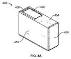
[0054] 図4A、図4B、図4C、図4D、および図4Eは、一実施形態に係る、空気冷却器の斜視図であって、その構成要素の相対位置および相互接続を示している。空気冷却器400は、空気冷却器130の一実施形態であってもよく、蒸気サイクル冷却システム300の一実施形態を含んでもよい。
[0054] FIGS. 4A, 4B, 4C, 4D, and 4E are perspective views of an air cooler according to one embodiment, showing the relative positions and interconnections of its components.
[0055] 空気冷却器400は、筐体上面404に冷却器空気入口402を具備する。他の実施形態において、冷却器空気入口402は、空気冷却器400の底面よりも上面404に相当近い空気冷却器400の上側領域または部分に存在していてもよい。冷却器空気入口402は、空気フィルタおよび付属装置(図示せず)を具備していてもよい。空気冷却器400の筐体は、ファラデーシールドを与えるように接地されて、内部生成高周波エネルギーを含みつつ、外部電磁干渉(EMI)の影響から空気冷却器400を遮蔽するのに役立ち得る。また、空気冷却器400の種々実施形態においては、EMIフィルタを具備することにより、伝導EMIおよび放射EMIに対する感受性を抑えるようにしてもよい。
The
[0056] 側方筐体パネル408は、冷却器空気入口402に隣接する側で空気冷却器400を囲んでいる。一方、側方筐体パネル406は、反対側で空気冷却器400を囲んでいる。前方筐体パネル410は、図面に見られるように、前側で空気冷却器400を囲んでいる。蒸発器ハウジング412は、冷却器空気入口402を通して、(たとえば、図3の還気305としての)還気を受容する。蒸発器ファン418は、冷却器空気入口402から蒸発器ハウジング412中の蒸発器434を通して循環させ、空気冷却器400の底面上の底部筐体パネル430にある冷却器空気出口428および冷却器空気出口開口432から(たとえば、図3の供給冷却空気304として)空気を排出する。蒸発器434は、図3の蒸発器336の一実施形態であってもよい。蒸発器ファン418は、蒸発器ファンモータによって駆動される。
The
[0057] 冷却ユニットハウジング414は、蒸発器ファンシュラウド416と蒸発器ハウジング412との間に位置付けられている。冷却ユニットハウジング414は、温度調節膨張弁436と、複数の冷却配管断片と、冷媒を圧縮器422に戻す冷媒戻し接続部438、冷媒を蒸発器434に供給する冷媒供給接続部440、および高温ガスを供給して蒸発器434の除霜を行う、冷媒高温ガス接続部442に対する接続部と、を収容している。圧縮器422は、図3の圧縮器302の一実施形態であってもよい。温度調節膨張弁436は、図3の膨張弁330の一実施形態であってもよい。蒸発器434は、液冷復水器426から流体冷媒を受容し、この流体冷媒を用いることにより、ファンブレード444を具備した蒸発器ファン418により蒸発器434から引き出され、蒸発器ファンシュラウド416を介して冷却器空気出口428から排出される空気を冷却する。液冷復水器426は、図3の液冷復水器306の一実施形態であってもよく、図3の液入口308および液出口310の実施形態である液入口450および液出口452を有していてもよい。流体冷媒は、蒸発器434から退出すると、圧縮器422に戻って再度圧縮され、蒸気サイクルシステムを流れ続ける。蒸発器434と圧縮器422との間において、冷媒は、図3に示すとともに図3を参照して説明したのと同様に、蒸発器434、圧縮器422、温度調節膨張弁436、およびフィルタ−乾燥機510(図5A)の間に結合された熱交換器328の一実施形態を通過してもよい。圧縮冷媒は、冷媒配管420を圧縮器422から液冷復水器426まで通過する。冷媒配管420は、図3の冷媒配管303の一実施形態であってもよい。
The cooling
[0058] 図4Bおよび図4Dにおいては、側方筐体パネル408と平行な配向かつ隣接して冷却器空気出口428および出口開口432を示しているが、代替としては、前方筐体パネル410の反対の後方筐体パネルと平行な配向かつ隣接している。空気冷却器400の底部または下側領域あるいは部分に冷却器空気出口428を位置決めすることによって、ギャレーカート載貨領域140および/またはギャレーカート150に空気を循環させる航空機ギャレー空気再循環システムの圧力低下を抑えることができる。
[0058] In FIGS. 4B and 4D, a
[0059] 図5A、図5B、図5C、図5D、図5E、図5F、および図5Gは、別の実施形態に係る、空気冷却器500の斜視図であって、その構成要素の相対位置および相互接続を示している。空気冷却器500は、空気冷却器400および空気冷却器130の一実施形態であってもよく、蒸気サイクル冷却システム300の一実施形態を含んでもよい。空気冷却器400を参照して上記説明した要素と実質的に同じ空気冷却器500の要素は、同じ参照番号を用いて識別される。図5Aに示すように、蒸発器ハウジング412には、断熱材530が巻かれている。また、液冷復水器426と膨張弁330との間では、冷媒フィルタ−乾燥機510が冷媒配管と結合されている。フィルタ−乾燥機510は、蒸気サイクル冷却システム300のフィルタ326の一実施形態であってもよい。フィルタ−乾燥機510は、一方側が冷媒供給接続部440に結合されていてもよい。また、蒸発器ファン418のファンモータの電気配線520を制御装置424と電気的に結合された状態で示している。また、図5Aおよび図5Bは、圧縮器422を液冷復水器426と結合する冷媒配管540を示している。
[0059] FIGS. 5A, 5B, 5C, 5D, 5E, 5F, and 5G are perspective views of an
[0060] 空気冷却器500は、図1の空気冷却器搭載箇所120に嵌合した小型ケース中に構成されていてもよい。たとえば、空気冷却器400および500の外側筐体は、幅が約8.6インチ、長さが24インチ、高さが15.75インチであってもよい。冷却器空気入口402は、約5.5インチ×10.6インチであってもよく、前方筐体パネルおよび後方筐体パネルから約1.6インチ、側方筐体パネル408から約1.5インチに配設されていてもよい。冷却器空気出口開口432は、約7.1インチ×2.2インチであってもよく、後方筐体パネルと平行な配向の場合に、後方筐体パネルから約0.6インチ、側方筐体パネル408から1.5インチに配設されていてもよい。
The
[0061] 空気冷却器500は、一実施形態に係る115/200VACの3相400Hz電源の相A(1)、相B(2)、および相C(3)のピンを含む制御装置424への電気的接続部を備えていてもよい。これらは、たとえば10ピンコネクタのピン1〜3として設けられていてもよい。他の実施形態においては、電気的接続部が異なる電圧および周波数値に対応していてもよい。また、電気的接続部には、障害信号のための電気的接続部(たとえば、ピン4)を含んでもよく、これは、障害接続ピンの信号がLowの場合にアクティブとなるものであってもよい。障害信号は、たとえばグランド接続時にLowであってもよい。通常の無障害動作において、障害信号電気的接続部は、別の電気的接続ピン(たとえば、ピン10)と電気的に接続されて、閉ループを形成していてもよい。別の電気的接続ピン(たとえば、ピン5)は、+28VDCを与えていてもよい。一方、別の電気的接続ピン(たとえば、ピン6)は、28VDCリターンを与えていてもよい。これらの28VCD電気的接続部(たとえば、ピン5および6)は、冷却器オン/オフ制御を提供していてもよい。別の電気的接続部(たとえば、ピン9)は、シャーシグランドを与えていてもよい。電気コネクタ(たとえば、10ピン電気コネクタ)の他の電気的接続部(たとえば、ピン7および8)は、不使用であってもよいし、本明細書に記載しない他の将来的な使用のために確保されていてもよい。
[0061] The
[0062] 以下の表1は、一実施形態に係る、蒸気サイクル冷却システム300を含む空気冷却器130の性能パラメータを示している。表中、CAX空気流の範囲は、110〜150l/sである。
[0062] Table 1 below shows performance parameters of an

[0063] 図6は、一実施形態に係る、空気冷却器の冷却容量対冷却剤流を示したグラフである。図7は、一実施形態に係る、空気冷却器の消費電力対冷却剤流を示したグラフである。図8は、一実施形態に係る、空気冷却器の冷却容量対CAX空気流および温度を示したグラフである。これらのグラフは、空気冷却器130、400、および500の実施形態の性能特性を示している。
[0063] FIG. 6 is a graph illustrating cooling capacity versus coolant flow of an air cooler, according to one embodiment. FIG. 7 is a graph illustrating air cooler power consumption versus coolant flow, according to one embodiment. FIG. 8 is a graph illustrating cooling capacity of an air cooler versus CAX airflow and temperature, according to one embodiment. These graphs show the performance characteristics of the embodiments of the
[0064] 図9は、一実施形態に係る、空気冷却器130、400、500または蒸気サイクル冷却システム300の制御装置900のブロック図である。制御装置900は、制御装置424の一実施形態であってもよいし、蒸気サイクル冷却システム300と結合されていてもよい。制御装置900は、I/Oインターフェース930を介して制御パネル940と結合されていてもよい。制御装置900は、冷却システムのオンまたはオフ、動作モードの選択、および所望温度の設定等、入力装置を介して、ユーザからの入力コマンドを受け取るようにしてもよい。制御装置900は、表示パネルを用いて、冷却システムの動作状態(たとえば、動作モード、除霜サイクルの有効化、蒸気サイクル冷却システム300の冷却区画および/または構成要素の温度過上昇状態に起因する遮断等)に関する情報をユーザに出力してもよい。制御装置900は、シールド付きツイストケーブルを用いて入力装置および表示パネルと結合されていてもよく、その電気的に堅牢な特性によりRS−232通信プロトコルを用いて入力装置および/または表示パネルと通信してもよい。制御装置900が結合可能な冷却装置、空気冷却器、および冷却機器の実施形態には、類似の表示パネルおよび入力装置が存在していてもよい。あるいは、制御装置900が結合可能な冷却装置、空気冷却器、および冷却機器の実施形態から遠隔に、類似の表示パネルおよび入力装置が設置されていてもよい。
[0064] FIG. 9 is a block diagram of the
[0065] 制御装置900は、プログラム命令に係る演算を実行するプロセッサ910と、プロセッサ910により使用または生成される演算命令および他のデータを記憶したメモリ920と、イーサネット、ギャレーデータバス(GAN)、またはコントローラエリアネットワーク(CAN)等のデータ通信ネットワーク990とインターフェースするためのデータ通信回路を含むネットワークインターフェース950とを具備していてもよい。プロセッサ910は、マイクロプロセッサ、フィールドプログラマブルゲートアレイ、特定用途向け集積回路、もしくはカスタム超大規模集積回路チップ、または制御機能を実行する他の電子回路を具備していてもよい。また、プロセッサ910は、状態機械を具備していてもよい。また、制御装置900は、1つまたは複数の電子回路およびプリント配線板を具備していてもよい。プロセッサ910、メモリ920、およびネットワークインターフェース950は、1つまたは複数のデータバス980を用いて互いに結合されていてもよい。制御装置900は、制御インターフェース960を介して、蒸気サイクル冷却システム300のさまざまなセンサおよびアクチュエータ970と通信し制御してもよい。
The
[0066] 制御装置900は、航空機内にあるような集中コンピュータシステムによる制御または通信が可能である。制御装置900は、適合ARINC810物理インターフェース上に適合ARINC812論理通信インターフェースを実装していてもよい。制御装置900は、ギャレーデータバス(たとえば、ギャレーネットワーク化GANバス)を介して通信を行うとともに、ギャレーネットワークコントローラ(たとえば、ARINC812仕様に記載されているマスターゲイン制御ユニット)とデータを交換してもよい。ARINC812仕様によれば、制御装置900は、ネットワーク監視、電力制御、遠隔操作、故障監視、およびデータ転送機能を提供してもよい。制御装置900は、GNCタッチパネル表示装置上での表示用にギャレーネットワーク制御装置(GNC)から受信したメニュー定義要求を実装するとともに、関連するボタン押下イベントを処理して適切に応答してもよい。制御装置900は、パーソナルコンピュータ(PC)または個人用デジタル補助装置(PDA)との通信等、RS−232通信インターフェースおよび/または赤外線データポートを用いて付加的な通信を提供してもよい。このような付加的な通信には、蒸気サイクル冷却システム300の動作の実時間監視、長期データ回復、および制御システムソフトウェアのアップグレードを含んでもよい。加えて、制御インターフェース960には、制御装置900と蒸気サイクル冷却システム300内のモータ制御装置との間の通信に使用可能なシリアルペリフェラルインターフェース(SPI)バスを含んでもよい。
[0066] The
[0067] 蒸気サイクル冷却システム300は、当該蒸気サイクル冷却システム300に動作可能に取り付けられる冷却または冷蔵区画に配置された飲料品および/または食料品を冷却するように構成されていてもよい。蒸気サイクル冷却システム300は、冷蔵、飲料冷却、および冷凍等の複数のモードのうちの1つまたは複数で動作してもよい。ユーザは、制御パネル940を用いて、冷却区画の所望の温度を選択してもよい。蒸気サイクル冷却システム300とともに備えられた制御装置900は、所望の温度に従って、高い精度で冷却区画内の温度を制御してもよい。これにより、冷却区画に貯蔵された食料品の品質は、蒸気サイクル冷却システム300のユーザ選択動作モードに従って維持されてもよい。
[0067] The steam cycle cooling system 300 may be configured to cool beverage and / or food items disposed in a cooling or refrigeration compartment operably attached to the steam cycle cooling system 300. The steam cycle cooling system 300 may operate in one or more of a plurality of modes such as refrigeration, beverage cooling, and freezing. The user may use the
[0068] 種々実施形態において、蒸気サイクル冷却システム300は、いくつかの予めプログラムされた温度のうちのユーザ選択可能なオプションまたは具体的なユーザ入力温度に従って、冷却区画内の温度を維持してもよい。たとえば、飲料冷却モードでは、冷却区画内の温度を約9℃、12℃、または16℃のユーザ選択可能な温度に維持してもよい。冷蔵器モードでは、冷却区画内の温度が約4℃または7℃のユーザ選択可能な温度に維持されてもよい。冷凍器モードでは、冷却区画内の温度が約−18℃〜0℃のユーザ選択可能な温度に維持されてもよい。 [0068] In various embodiments, the steam cycle cooling system 300 may maintain the temperature in the cooling compartment according to a user-selectable option or a specific user input temperature of several pre-programmed temperatures. Good. For example, in the beverage cooling mode, the temperature in the cooling compartment may be maintained at a user selectable temperature of about 9 ° C, 12 ° C, or 16 ° C. In the refrigerator mode, the temperature in the cooling compartment may be maintained at a user selectable temperature of about 4 ° C or 7 ° C. In the freezer mode, the temperature in the cooling compartment may be maintained at a user-selectable temperature of about −18 ° C. to 0 ° C.
[0069] 制御装置900は、蒸気サイクル冷却システム300内の1つまたは複数の冷却システムの実時間動作のための時間で、蒸気サイクル冷却システム300の性能の制御に必要なすべてのデータを時間内に取得できるように、一定の最小レートでセンサのポーリングを行うようにしてもよい。ポーリングされた値は、RS−232または赤外線インターフェースを介して、制御装置900によりパーソナルコンピュータまたはPDAに報告されてもよく、コントローラエリアネットワーク(CAN)バス上で報告されてもよい。また、ポーリング値は、制御装置900によって制御アルゴリズムに用いられてもよく、また、長期メモリまたはデータ記憶媒体に記憶され、後で読み出しおよび解析が行われてもよい。
[0069] The
[0070] 制御装置900は、温度過上昇状態、圧力過上昇状態、電流過上昇状態等の異常な外部および/または内部イベントに起因する蒸気サイクル冷却システム300およびその構成要素の損傷を防止する自己保護方式を提供するとともに、異常なイベントに応じて、蒸気サイクル冷却システム300ならびに/またはその構成要素のうちの1つもしくは複数を停止してもよい。自己保護方式には、重要なシステムセンサの監視およびセンサからの監視データが自己保護動作の有効化を要する問題を示している場合の然るべき自己保護動作の実行を含んでもよい。このような自己保護動作によって、蒸気サイクル冷却システム300および/またはその構成要素は、損傷を受けたり危険な状況を生じたりすることを防止可能である。また、自己保護動作により、表示パネルを介して、監視問題、自己保護動作、および/または任意の関連する所要保守に関する適当な通知を与えるようにしてもよい。制御装置の自己保護方式は、蒸気サイクル冷却システム300内に展開し得る機械的な保護装置の置き換えではなく、これを補完するものであってもよい。制御装置900は、自己保護停止をもたらした異常なイベントの終了または程度の軽減後、センサからの監視データを用いて、蒸気サイクル冷却システム300を知的に再起動するとともに、所望の動作モードを再開させるようにしてもよい。
[0070] The
[0071] 蒸気サイクル冷却システム300は、制御装置900と関連付けられた電子制御システムにより制御されてもよい。制御装置900のメモリ920は、プロセッサ910により実行可能な蒸気サイクル冷却システム300の制御方法を実行するプログラムを記憶していてもよい。電子制御システムが実行する蒸気サイクル冷却システム300の制御方法には、蒸気サイクル冷却システム300が結合される飲食料品貯蔵区画の所定温度を蒸気サイクル冷却システム300が自動的に維持できるように、フィードバック制御システムを含んでもよい。
[0071] Steam cycle cooling system 300 may be controlled by an electronic control system associated with
[0072] 航空機ギャレー空気冷却器130は、列線交換ユニット(LRU)であってもよく、航空機が地上にある場合および飛行中の両者において、冷却機能を提供してもよい。冷却は、本明細書のような冷却システムを用いて与えられてもよい。空気冷却器130は、ARINC810規格に従って設計されていてもよい。空気冷却器130は、3相115〜200ボルト周波数交流(AC)等の電源を用いて、360〜900Hzの周波数で動作するように構成されていてもよい。蒸気サイクル冷却システム300は、AC/DC電力変換を採用することにより、予測可能かつ一貫した電源をモータおよび/または弁アクチュエータに提供してもよい。また、空気冷却器130は、多相変成器(たとえば、15パルス変成器)を具備することにより、当該空気冷却器130が結合可能な機体配電システムに反射して戻る電流高調波を抑えるようにしてもよい。
[0072] Aircraft
[0073] 図10は、一実施形態に係る、液体排熱システムを有する移動体冷却装置の稼働方法のフローチャートである。工程1010において、空気冷却器は、圧縮器、液冷復水器、および蒸発器の間の配管を通して冷媒を循環させるようにしてもよい。工程1020において、冷却システムは、移動体の中央冷却液冷却システムと空気冷却器の液冷復水器との間の冷却液ラインを通して冷却液を循環させるようにしてもよい。移動体の中央冷却液冷却システムが冷却液を冷却してもよい。たとえば、中央冷却液冷却システムは、蒸気サイクルシステムまたは移動体外部の空気による冷たい空気流を用いて、冷却液を冷却してもよい。工程1030においては、空気冷却器の配管を循環する冷媒から冷却液ラインを循環する冷却液に熱が伝達されてもよい。工程1040においては、空気冷却器の蒸発器と複数の取り外し可能な貯蔵区画を載荷する内部を有する貯蔵区画載貨領域との間のダクトシステムを通して空気が循環してもよい。空気冷却器は、取り外し可能な貯蔵区画の取り外しおよび取り替え方向に垂直な平面に沿って、貯蔵区画載貨領域に平行に位置付けられていてもよい。空気は、取り外し可能な貯蔵区画の取り外しおよび取り替えが行われる貯蔵区画載貨領域の前面に対して、取り外し可能な貯蔵区画の背後のダクトを循環しなくてもよい。工程1050において、空気冷却器は、蒸発器によって空気を冷やすようにしてもよい。
FIG. 10 is a flowchart of a method for operating a moving body cooling apparatus having a liquid exhaust heat system according to an embodiment. In step 1010, the air cooler may cause the refrigerant to circulate through piping between the compressor, the liquid-cooled condenser, and the evaporator. In
[0074] 本明細書に引用の刊行物、特許出願、および特許を含むすべての参考文献は、それぞれが援用を個別かつ具体的に指示され、そのすべてが本明細書に記載されるのと同じ程度まで本明細書に援用する。 [0074] All references, including publications, patent applications, and patents cited herein are each individually and specifically indicated for incorporation, all as described herein. To the extent incorporated herein.
[0075] 本発明の原理の理解を促進するため、図面に示す実施形態を参照するとともに、特定の表現を用いてこれら実施形態を説明した。ただし、本発明の範囲は、この特定の表現によって限定されるものではなく、本発明は、当業者が通常想到し得るあらゆる実施形態を含むものと解釈すべきである。本明細書で使用する専門用語は、特定の実施形態を説明することを目的としており、本発明の例示的な実施形態を限定するものではない。 [0075] To facilitate an understanding of the principles of the invention, reference has been made to the embodiments illustrated in the drawings and specific embodiments have been used to describe the embodiments. However, the scope of the present invention is not limited by this specific expression, and the present invention should be construed to include any embodiment that would normally occur to one skilled in the art. The terminology used herein is for the purpose of describing particular embodiments and is not intended to limit the exemplary embodiments of the invention.
[0076] 本明細書に記載の装置は、プロセッサと、当該プロセッサが実行するプログラムデータを記憶するメモリと、ディスクドライブ等の永続ストレージと、外部装置との通信を担う通信ポートと、ディスプレイ、キー等のユーザインターフェース装置とを備えていてもよい。ソフトウェアモジュールが関与する場合、これらのソフトウェアモジュールは、プロセッサにより実行可能なプログラム命令またはコンピュータ可読コードとして、読出し専用メモリ(ROM)、ランダムアクセスメモリ(RAM)、CD−ROM、DVD、磁気テープ、ハードディスク、フロッピーディスク、および光学データ記憶装置等の持続性コンピュータ可読媒体に記憶されていてもよい。また、コンピュータ可読記録媒体は、コンピュータ可読コードが分散して記憶および実行されるように、ネットワーク結合されたコンピュータシステム上で分散されてもよい。この媒体は、コンピュータによって読み取られ、メモリへ記憶され、およびプロセッサによって実行されてもよい。 [0076] An apparatus described in this specification includes a processor, a memory for storing program data executed by the processor, a permanent storage such as a disk drive, a communication port for communication with an external device, a display, a key Or a user interface device such as When software modules are involved, these software modules can be read-only memory (ROM), random access memory (RAM), CD-ROM, DVD, magnetic tape, hard disk as program instructions or computer readable code executable by a processor. , Floppy disks, and optical data storage such as persistent computer readable media. The computer readable recording medium may also be distributed over a network coupled computer system so that the computer readable code is stored and executed in a distributed fashion. This medium may be read by a computer, stored in memory, and executed by a processor.
[0077] また、本明細書の開示内容を用いることにより、本発明が関係する技術分野において通常の技量を有するプログラマであれば、本発明を作製および使用するための機能プログラム、コード、およびコードセグメントを容易に実装可能である。 [0077] Further, by using the disclosed contents of the present specification, a functional program, code, and code for making and using the present invention can be used by a programmer having ordinary skill in the technical field to which the present invention relates. Segments can be easily implemented.
[0078] 本発明は、機能ブロック構成要素およびさまざまな処理工程の観点で説明し得る。このような機能ブロックは、特定の機能を実行するように構成された任意数のハードウェアおよび/またはソフトウェアコンポーネントにより実現されていてもよい。たとえば、本発明は、1つまたは複数のマイクロプロセッサ等の制御デバイスの制御下で多様な機能を実行し得る、たとえばメモリ要素、処理要素、論理要素、ルックアップテーブル等のさまざまな集積回路構成要素を採用していてもよい。同様に、本発明の要素がソフトウェアプログラミングまたはソフトウェア要素を用いて実装される場合、本発明は、C、C++、Java、アセンブラ等の任意のプログラミングまたはスクリプト言語により実装されていてもよく、データ構造、オブジェクト、プロセス、ルーチン等のプログラミング要素の任意の組み合わせによって、さまざまなアルゴリズムが実装され得る。機能的態様は、1つまたは複数のプロセッサ上で実行するアルゴリズムにおいて実装されていてもよい。さらに、本発明は、電子機器構成、信号処理および/または制御、データ処理等に関する任意数の従来技法を採用していてもよい。最後に、本明細書に記載のすべての方法の各工程は、本明細書における特段の指示または文脈上の明確な矛盾がない限り、任意の好適な順序で実行されてもよい。 [0078] The present invention may be described in terms of functional block components and various processing steps. Such functional blocks may be implemented by any number of hardware and / or software components configured to perform specific functions. For example, the present invention provides various integrated circuit components such as memory elements, processing elements, logic elements, look-up tables, etc. that can perform various functions under the control of a control device such as one or more microprocessors. May be adopted. Similarly, if the elements of the present invention are implemented using software programming or software elements, the present invention may be implemented in any programming or scripting language such as C, C ++, Java, assembler, etc. Various algorithms may be implemented by any combination of programming elements such as objects, processes, routines, etc. Functional aspects may be implemented in algorithms that execute on one or more processors. Further, the present invention may employ any number of conventional techniques relating to electronic equipment configuration, signal processing and / or control, data processing, and the like. Finally, the steps of all methods described herein may be performed in any suitable order unless otherwise indicated herein or otherwise clearly contradicted by context.
[0079] 簡略化のため、従来の電子機器、制御システム、ソフトウェア開発、およびシステムの他の機能的態様(および、システムの個々の動作構成要素の構成要素)は、詳しく説明していない場合がある。さらに、提示したさまざまな図面に示す連結線または連結部は、さまざまな要素間の例示的な機能的関係ならびに/または物理的もしくは論理的結合を表すものである。実際の装置においては、多くの代替的または付加的な機能的関係、物理的連結、または論理的連結が存在し得ることに留意するものとする。単語「機構」および「要素」は、広く使用しており、機械的または物理的な実施形態に限定されず、プロセッサ等とともにソフトウェアルーチンを含んでもよい。 [0079] For simplicity, conventional electronics, control systems, software development, and other functional aspects of the system (and components of the individual operating components of the system) may not be described in detail. is there. Further, the connecting lines or connections shown in the various presented drawings represent exemplary functional relationships and / or physical or logical connections between the various elements. It should be noted that in an actual device, there can be many alternative or additional functional relationships, physical connections, or logical connections. The words “mechanism” and “element” are widely used and are not limited to mechanical or physical embodiments, but may include software routines along with a processor or the like.
[0080] 本明細書に提示のありとあらゆる例または例示的な表現(たとえば、「〜等」)の使用は、本発明をより明確化することのみを意図しており、特段の要求のない限り、本発明の範囲に何ら制約を課すものではない。当業者には、以下の特許請求の範囲により規定される本発明の主旨および範囲から逸脱することなく、多くの改良および適応が容易に明らかとなるであろう。したがって、本発明の範囲は、本発明の詳細な説明ではなく、以下の特許請求の範囲によって規定され、この範囲内のあらゆる相違は、本発明に含まれるものと解釈される。 [0080] The use of any and all examples or exemplary expressions (e.g., "... etc.") Presented herein is intended only to clarify the present invention and, unless otherwise required, There are no restrictions on the scope of the present invention. Many modifications and adaptations will be readily apparent to those skilled in the art without departing from the spirit and scope of the invention as defined by the following claims. Accordingly, the scope of the invention is defined by the following claims rather than the detailed description of the invention, and any differences within this scope are to be construed as being included in the invention.
[0081] 物品または構成要素は、当該要素が「必須」または「重要」と具体的に記載されていない限り、本発明の実施に必須ではない。また、本明細書において使用される場合、用語「備える」、「備えている」、「具備する」、「具備している、「有する」、および「有している」は、オープンエンドな技術用語として解釈されることを具体的に意図したものであることが認識されよう。本発明の説明の文脈(特に、以下の特許請求の範囲の文脈)における用語「a」、「an」、および「the」、ならびに類似の指示対象の使用は、文脈上の明確な別段の指示がない限り、単数形および複数形の両者を含むものと解釈されるものとする。加えて、本明細書においては、用語「第1」、「第2」等を用いてさまざまな要素を説明する場合があるが、これらの要素は、これらの用語によって限定されるものではなく、ある要素を別の要素と区別するために使用しているに過ぎないことが了解されるものとする。さらに、本明細書における値の範囲の記述は、本明細書における特段の指示がない限り、当該範囲内の各別個の値を個々に参照する簡潔な方法として機能することを意図したに過ぎず、各別個の値は、本明細書において個々に列挙されるかの如く、本明細書に援用する。 [0081] Articles or components are not essential to the practice of the invention unless the element is specifically described as "essential" or "important". Also, as used herein, the terms “comprising”, “comprising”, “comprising”, “comprising”, “having”, and “having” are open-ended technologies. It will be appreciated that it is specifically intended to be interpreted as a term. The use of the terms “a”, “an”, and “the”, and similar referents, in the context of the description of the present invention, and in particular the context of the following claims, is intended to be clearly distinctive in the context. Unless otherwise, it shall be construed as including both the singular and plural forms. In addition, in the present specification, various elements may be described using the terms “first”, “second”, etc., but these elements are not limited by these terms, It is understood that an element is only used to distinguish one element from another. Further, the description of a range of values herein is intended only to serve as a concise way to individually reference each distinct value within the range, unless otherwise indicated herein. Each distinct value is incorporated herein as if it were individually listed herein.
Claims (14)
空気冷却器であって、
圧縮器と、
液冷復水器と、
蒸発器と、
前記空気冷却器を通して、前記圧縮器から前記液冷復水器、前記蒸発器に至り、前記圧縮器に戻すように冷媒を循環させる配管と、
を備えた、空気冷却器と、
冷却液ラインであって、冷却液を冷却する移動体の中央冷却液冷却システムと、前記配管を循環する前記冷媒から前記冷却液ラインを循環する前記冷却液に熱を伝える前記液冷復水器との間で前記冷却液を循環させる、冷却液ラインと、
複数の取り外し可能な貯蔵区画を載貨する内部を有する貯蔵区画載貨領域と、
前記貯蔵区画載貨領域と前記空気冷却器との間に流体連通したダクトシステムであって、前記空気冷却器が、前記取り外し可能な貯蔵区画の取り外しおよび取り替え方向に垂直な平面に沿って、前記貯蔵区画載貨領域に平行に位置付けられ、前記ダクトシステムが、前記蒸発器から前記貯蔵区画載貨領域の内部を通して冷却空気を循環させるとともに、前記貯蔵区画載貨領域の内部から前記蒸発器に還気を返し、前記取り外し可能な貯蔵区画の背後にダクトを含まない、ダクトシステムと、
を備えた、冷却システム。 A cooling system for cooling a removable storage compartment in a mobile galley,
An air cooler,
A compressor;
A liquid-cooled condenser,
An evaporator,
Through the air cooler, from the compressor to the liquid-cooled condenser, the evaporator, and a pipe for circulating a refrigerant so as to return to the compressor;
An air cooler with
A cooling liquid line, a central cooling liquid cooling system for a moving body for cooling the cooling liquid, and the liquid cooling condenser for transferring heat from the refrigerant circulating in the piping to the cooling liquid circulating in the cooling liquid line A coolant line for circulating the coolant between
A storage compartment loading area having an interior for loading a plurality of removable storage compartments;
A duct system in fluid communication between the storage compartment loading area and the air cooler, wherein the air cooler is located along a plane perpendicular to the removal and replacement direction of the removable storage compartment. Positioned parallel to the compartment loading area, the duct system circulates cooling air from the evaporator through the interior of the storage compartment loading area, and returns return air from the inside of the storage compartment loading area to the evaporator, A duct system that does not include a duct behind the removable storage compartment; and
With cooling system.
空気冷却器の圧縮器、液冷復水器、および蒸発器の間の配管を通して冷媒を循環させる工程と、
冷却液を冷却する移動体の中央冷却液冷却システムと前記液冷復水器との間の冷却液ラインを通して前記冷却液を循環させる工程と、
前記配管を循環する前記冷媒から前記冷却液ラインを循環する前記冷却液に熱を伝える工程と、
前記空気冷却器の蒸発器と複数の取り外し可能な貯蔵区画を載貨する内部を有する貯蔵区画載貨領域との間のダクトシステムを通して空気を循環させる工程であって、前記空気冷却器が、前記取り外し可能な貯蔵区画の取り外しおよび取り替え方向に垂直な平面に沿って、前記貯蔵区画載貨領域に平行に位置付けられ、前記ダクトシステムが、前記蒸発器から前記貯蔵区画載貨領域の内部を通して冷却空気を循環させるとともに、前記貯蔵区画載貨領域の内部から前記蒸発器に還気を返し、前記取り外し可能な貯蔵区画の背後にダクトを含まない、工程と、
前記空気冷却器の前記蒸発器によって前記空気を冷却する工程と、
を含む、方法。 A method for cooling a removable storage compartment in a mobile galley, comprising:
Circulating the refrigerant through the piping between the compressor of the air cooler, the liquid-cooled condenser, and the evaporator;
Circulating the coolant through a coolant line between a central coolant cooling system of a mobile that cools the coolant and the liquid-cooled condenser;
Transferring heat from the refrigerant circulating in the piping to the cooling liquid circulating in the cooling liquid line;
Circulating air through a duct system between an evaporator of the air cooler and a storage compartment loading area having an interior for loading a plurality of removable storage compartments, wherein the air cooler is removable Positioned parallel to the storage compartment loading area along a plane perpendicular to the direction of removal and replacement of the storage compartment, and the duct system circulates cooling air from the evaporator through the interior of the storage compartment loading area Returning the return air from the interior of the storage compartment loading area to the evaporator and not including a duct behind the removable storage compartment ; and
Cooling the air by the evaporator of the air cooler;
Including a method.
Applications Claiming Priority (3)
| Application Number | Priority Date | Filing Date | Title |
|---|---|---|---|
| US201461969770P | 2014-03-24 | 2014-03-24 | |
| US61/969,770 | 2014-03-24 | ||
| PCT/US2015/022219 WO2015148486A1 (en) | 2014-03-24 | 2015-03-24 | Vehicle refrigeration equipment having a liquid heat rejection system |
Publications (2)
| Publication Number | Publication Date |
|---|---|
| JP2017517709A JP2017517709A (en) | 2017-06-29 |
| JP6419837B2 true JP6419837B2 (en) | 2018-11-07 |
Family
ID=54141297
Family Applications (1)
| Application Number | Title | Priority Date | Filing Date |
|---|---|---|---|
| JP2016556803A Active JP6419837B2 (en) | 2014-03-24 | 2015-03-24 | Moving body cooling apparatus having liquid heat exhaust system |
Country Status (6)
| Country | Link |
|---|---|
| US (1) | US10450069B2 (en) |
| EP (1) | EP3123085B1 (en) |
| JP (1) | JP6419837B2 (en) |
| CN (1) | CN106133465A (en) |
| CA (1) | CA2941752C (en) |
| WO (1) | WO2015148486A1 (en) |
Families Citing this family (19)
| Publication number | Priority date | Publication date | Assignee | Title |
|---|---|---|---|---|
| CN104380014A (en) | 2012-03-22 | 2015-02-25 | B/E航空公司 | Vehicle refrigeration equipment having a vapor cycle system |
| EP2933190B1 (en) * | 2014-04-14 | 2021-09-15 | Airbus Operations GmbH | Galley cooling system and method of operating a galley cooling system |
| US11072426B2 (en) * | 2015-11-23 | 2021-07-27 | The Boeing Company | Galley system of an aircraft |
| US10207807B2 (en) * | 2016-04-13 | 2019-02-19 | The Boeing Company | Condensate removal system of an aircraft cooling system |
| US10488100B2 (en) * | 2016-11-09 | 2019-11-26 | Honeywell International Inc. | Supplemental cooling system load control using random start of first defrost cycle |
| CN107356035B (en) * | 2017-08-22 | 2023-08-04 | 合肥天鹅制冷科技有限公司 | Large-scale movable liquid cooling equipment |
| US10337776B2 (en) * | 2017-09-19 | 2019-07-02 | The Boeing Company | Refrigeration system having valves and valve control actuators |
| DE102017126693A1 (en) * | 2017-11-14 | 2019-05-16 | Airbus Operations Gmbh | Cooling arrangement for a galley and galley |
| CN109831891B (en) * | 2017-11-23 | 2024-05-10 | 维谛技术有限公司 | Heat dissipation system, heat dissipation control method and heat dissipation control device of liquid cooling server |
| US11661199B2 (en) * | 2019-10-21 | 2023-05-30 | Peter Schiff | Removable auxiliary air conditioning system for a confined area |
| US11286049B2 (en) | 2019-11-12 | 2022-03-29 | B/E Aerospace, Inc. | Standard unit meal box compartment including air chiller |
| US11591093B2 (en) * | 2020-04-29 | 2023-02-28 | The Boeing Company | Variable chiller exhaust with crown ventilation |
| JP7518525B2 (en) | 2020-05-12 | 2024-07-18 | 森岡エステート株式会社 | Wine bottle storage locker, method for cooling and storing wine bottles |
| US11796223B2 (en) * | 2020-09-15 | 2023-10-24 | B/E Aerospace, Inc. | System for preventing overheating in aircraft galley inserts |
| US11560042B2 (en) * | 2021-06-24 | 2023-01-24 | Ford Global Technologies, Llc | Heat pump refrigerant loop arrangements |
| US20230400241A1 (en) * | 2022-06-08 | 2023-12-14 | B/E Aerospace, Inc. | Method for packaging and ducting a micro-chiller-style heat sink into a cart bay or other enclosure for optimal air circulation |
| US20230400231A1 (en) * | 2022-06-08 | 2023-12-14 | B/E Aerospace, Inc. | High efficiency micro-chiller unit |
| US12130069B2 (en) | 2022-08-23 | 2024-10-29 | Peter Berkeley | Vehicle refrigeration system for food carts |
| EP4400422A1 (en) * | 2023-01-13 | 2024-07-17 | B/E Aerospace (UK) Limited | Aircraft chilling system architecture |
Family Cites Families (19)
| Publication number | Priority date | Publication date | Assignee | Title |
|---|---|---|---|---|
| US3199579A (en) | 1960-02-11 | 1965-08-10 | Foster Refrigerator Corp | Heating and cooling food storage cabinet |
| US4361014A (en) * | 1981-03-19 | 1982-11-30 | Sundstrand Corporation | Panel air chiller |
| JPH0532985U (en) * | 1991-10-01 | 1993-04-30 | 昭和飛行機工業株式会社 | Refrigeration container |
| JP2500344Y2 (en) * | 1993-01-08 | 1996-06-05 | サンヨー調理機株式会社 | Greenhouse structure in catering car |
| DE19839050C1 (en) * | 1998-08-28 | 2000-02-17 | Frigoblock Groskopf Gmbh | Coolable body for a truck, trailer or semi-trailer |
| US7024874B2 (en) * | 2003-09-22 | 2006-04-11 | Hamilton Sundstrand | Aircraft galley chiller system |
| JP2005134002A (en) | 2003-10-29 | 2005-05-26 | Jamco Corp | Air chiller device |
| US7231778B2 (en) * | 2004-03-29 | 2007-06-19 | Be Intellectual Property, Inc. | Cooling system for a commercial aircraft galley |
| US8721409B1 (en) * | 2007-07-31 | 2014-05-13 | Amazon Technologies, Inc. | Airflow control system with external air control |
| US20100050665A1 (en) * | 2007-08-13 | 2010-03-04 | B/E Aerospace, Inc. | Method and apparatus for maintaining a uniform temperature in a refrigeration system |
| WO2009149320A1 (en) | 2008-06-05 | 2009-12-10 | B/E Aerospace, Inc. | Aircraft galley refrigeration system including a reduced weight and depth storage compartment cooling apparatus |
| US9238398B2 (en) * | 2008-09-25 | 2016-01-19 | B/E Aerospace, Inc. | Refrigeration systems and methods for connection with a vehicle's liquid cooling system |
| WO2010101972A1 (en) * | 2009-03-04 | 2010-09-10 | B/E Aerospace, Inc. | Wall-mounted point-of-use air chiller for aircraft galley cart compartment |
| US8308101B2 (en) | 2009-03-09 | 2012-11-13 | The Boeing Company | Simplified fiber tensioning for automated fiber placement machines |
| US20120291459A1 (en) * | 2011-05-17 | 2012-11-22 | The Boeing Company | Method and apparatus for aircraft galley cooling |
| CA2846057C (en) * | 2011-08-30 | 2015-04-21 | B/E Aerospace, Inc. | Reconfigurable chilled air outlet for an aircraft galley chiller |
| CN104380014A (en) | 2012-03-22 | 2015-02-25 | B/E航空公司 | Vehicle refrigeration equipment having a vapor cycle system |
| US9862496B2 (en) * | 2012-03-30 | 2018-01-09 | B/E Aerospace, Inc. | Aircraft galley chiller system |
| US9676483B2 (en) * | 2013-07-03 | 2017-06-13 | B/E Aerospace, Inc. | Aircraft galley air chiller system |
-
2015
- 2015-03-24 US US14/666,921 patent/US10450069B2/en active Active
- 2015-03-24 CN CN201580015768.9A patent/CN106133465A/en active Pending
- 2015-03-24 EP EP15769982.8A patent/EP3123085B1/en active Active
- 2015-03-24 JP JP2016556803A patent/JP6419837B2/en active Active
- 2015-03-24 WO PCT/US2015/022219 patent/WO2015148486A1/en active Application Filing
- 2015-03-24 CA CA2941752A patent/CA2941752C/en active Active
Also Published As
| Publication number | Publication date |
|---|---|
| US20150266353A1 (en) | 2015-09-24 |
| CN106133465A (en) | 2016-11-16 |
| CA2941752C (en) | 2018-04-10 |
| JP2017517709A (en) | 2017-06-29 |
| US10450069B2 (en) | 2019-10-22 |
| WO2015148486A1 (en) | 2015-10-01 |
| EP3123085A1 (en) | 2017-02-01 |
| EP3123085A4 (en) | 2017-11-08 |
| EP3123085B1 (en) | 2020-06-17 |
| CA2941752A1 (en) | 2015-10-01 |
Similar Documents
| Publication | Publication Date | Title |
|---|---|---|
| JP6419837B2 (en) | Moving body cooling apparatus having liquid heat exhaust system | |
| JP5774630B2 (en) | Cooling system and method for coupling a cooling system to a liquid cooling system of a vehicle | |
| EP2748541B1 (en) | Vehicle refrigerator having a liquid line subcooled vapor cycle system | |
| US10488084B2 (en) | Vehicle refrigeration equipment having a vapor cycle system | |
| US9188380B2 (en) | Aircraft galley liquid cooling system | |
| US20170038122A1 (en) | Vehicle Refrigeration System Utilizing Individually Controllable Galley Cart Fans | |
| EP2801526A1 (en) | Galley cooling heat exchanger defrost mechanism |
Legal Events
| Date | Code | Title | Description |
|---|---|---|---|
| A977 | Report on retrieval |
Free format text: JAPANESE INTERMEDIATE CODE: A971007 Effective date: 20171031 |
|
| A131 | Notification of reasons for refusal |
Free format text: JAPANESE INTERMEDIATE CODE: A131 Effective date: 20171106 |
|
| A601 | Written request for extension of time |
Free format text: JAPANESE INTERMEDIATE CODE: A601 Effective date: 20180206 |
|
| A601 | Written request for extension of time |
Free format text: JAPANESE INTERMEDIATE CODE: A601 Effective date: 20180403 |
|
| A521 | Request for written amendment filed |
Free format text: JAPANESE INTERMEDIATE CODE: A523 Effective date: 20180502 |
|
| TRDD | Decision of grant or rejection written | ||
| A01 | Written decision to grant a patent or to grant a registration (utility model) |
Free format text: JAPANESE INTERMEDIATE CODE: A01 Effective date: 20181003 |
|
| A61 | First payment of annual fees (during grant procedure) |
Free format text: JAPANESE INTERMEDIATE CODE: A61 Effective date: 20181010 |
|
| R150 | Certificate of patent or registration of utility model |
Ref document number: 6419837 Country of ref document: JP Free format text: JAPANESE INTERMEDIATE CODE: R150 |
|
| R250 | Receipt of annual fees |
Free format text: JAPANESE INTERMEDIATE CODE: R250 |
|
| R250 | Receipt of annual fees |
Free format text: JAPANESE INTERMEDIATE CODE: R250 |
|
| R250 | Receipt of annual fees |
Free format text: JAPANESE INTERMEDIATE CODE: R250 |
|
| R250 | Receipt of annual fees |
Free format text: JAPANESE INTERMEDIATE CODE: R250 |