EP3822161B1 - Outflow valve assembly including sound absorption and aircraft including the same - Google Patents
Outflow valve assembly including sound absorption and aircraft including the same Download PDFInfo
- Publication number
- EP3822161B1 EP3822161B1 EP20202237.2A EP20202237A EP3822161B1 EP 3822161 B1 EP3822161 B1 EP 3822161B1 EP 20202237 A EP20202237 A EP 20202237A EP 3822161 B1 EP3822161 B1 EP 3822161B1
- Authority
- EP
- European Patent Office
- Prior art keywords
- louver
- outflow valve
- aircraft
- valve assembly
- opening
- Prior art date
- Legal status (The legal status is an assumption and is not a legal conclusion. Google has not performed a legal analysis and makes no representation as to the accuracy of the status listed.)
- Active
Links
Images



Classifications
-
- B—PERFORMING OPERATIONS; TRANSPORTING
- B64—AIRCRAFT; AVIATION; COSMONAUTICS
- B64D—EQUIPMENT FOR FITTING IN OR TO AIRCRAFT; FLIGHT SUITS; PARACHUTES; ARRANGEMENT OR MOUNTING OF POWER PLANTS OR PROPULSION TRANSMISSIONS IN AIRCRAFT
- B64D13/00—Arrangements or adaptations of air-treatment apparatus for aircraft crew or passengers, or freight space
- B64D13/02—Arrangements or adaptations of air-treatment apparatus for aircraft crew or passengers, or freight space the air being pressurised
-
- B—PERFORMING OPERATIONS; TRANSPORTING
- B64—AIRCRAFT; AVIATION; COSMONAUTICS
- B64D—EQUIPMENT FOR FITTING IN OR TO AIRCRAFT; FLIGHT SUITS; PARACHUTES; ARRANGEMENT OR MOUNTING OF POWER PLANTS OR PROPULSION TRANSMISSIONS IN AIRCRAFT
- B64D13/00—Arrangements or adaptations of air-treatment apparatus for aircraft crew or passengers, or freight space
- B64D13/06—Arrangements or adaptations of air-treatment apparatus for aircraft crew or passengers, or freight space the air being conditioned
-
- B—PERFORMING OPERATIONS; TRANSPORTING
- B64—AIRCRAFT; AVIATION; COSMONAUTICS
- B64C—AEROPLANES; HELICOPTERS
- B64C1/00—Fuselages; Constructional features common to fuselages, wings, stabilising surfaces or the like
- B64C1/40—Sound or heat insulation, e.g. using insulation blankets
-
- B—PERFORMING OPERATIONS; TRANSPORTING
- B64—AIRCRAFT; AVIATION; COSMONAUTICS
- B64D—EQUIPMENT FOR FITTING IN OR TO AIRCRAFT; FLIGHT SUITS; PARACHUTES; ARRANGEMENT OR MOUNTING OF POWER PLANTS OR PROPULSION TRANSMISSIONS IN AIRCRAFT
- B64D41/00—Power installations for auxiliary purposes
-
- B—PERFORMING OPERATIONS; TRANSPORTING
- B64—AIRCRAFT; AVIATION; COSMONAUTICS
- B64F—GROUND OR AIRCRAFT-CARRIER-DECK INSTALLATIONS SPECIALLY ADAPTED FOR USE IN CONNECTION WITH AIRCRAFT; DESIGNING, MANUFACTURING, ASSEMBLING, CLEANING, MAINTAINING OR REPAIRING AIRCRAFT, NOT OTHERWISE PROVIDED FOR; HANDLING, TRANSPORTING, TESTING OR INSPECTING AIRCRAFT COMPONENTS, NOT OTHERWISE PROVIDED FOR
- B64F5/00—Designing, manufacturing, assembling, cleaning, maintaining or repairing aircraft, not otherwise provided for; Handling, transporting, testing or inspecting aircraft components, not otherwise provided for
- B64F5/10—Manufacturing or assembling aircraft, e.g. jigs therefor
-
- G—PHYSICS
- G10—MUSICAL INSTRUMENTS; ACOUSTICS
- G10K—SOUND-PRODUCING DEVICES; METHODS OR DEVICES FOR PROTECTING AGAINST, OR FOR DAMPING, NOISE OR OTHER ACOUSTIC WAVES IN GENERAL; ACOUSTICS NOT OTHERWISE PROVIDED FOR
- G10K11/00—Methods or devices for transmitting, conducting or directing sound in general; Methods or devices for protecting against, or for damping, noise or other acoustic waves in general
- G10K11/16—Methods or devices for protecting against, or for damping, noise or other acoustic waves in general
- G10K11/161—Methods or devices for protecting against, or for damping, noise or other acoustic waves in general in systems with fluid flow
-
- G—PHYSICS
- G10—MUSICAL INSTRUMENTS; ACOUSTICS
- G10K—SOUND-PRODUCING DEVICES; METHODS OR DEVICES FOR PROTECTING AGAINST, OR FOR DAMPING, NOISE OR OTHER ACOUSTIC WAVES IN GENERAL; ACOUSTICS NOT OTHERWISE PROVIDED FOR
- G10K11/00—Methods or devices for transmitting, conducting or directing sound in general; Methods or devices for protecting against, or for damping, noise or other acoustic waves in general
- G10K11/16—Methods or devices for protecting against, or for damping, noise or other acoustic waves in general
- G10K11/162—Selection of materials
- G10K11/168—Plural layers of different materials, e.g. sandwiches
Definitions
- the technical field relates generally to an outflow valve for an aircraft, and more particularly, relates to an outflow valve assembly for an aircraft including noise attenuation, an aircraft including such an outflow valve assembly, and a method for assembling such an outflow valve assembly to an aircraft.
- Outflow valves are commonly used in aircraft to vent the interior of the aircraft including the cockpit and cabin areas and to adjust cabin pressure.
- the outflow valve includes one or more flaps or louvers that are placed in an opening that is formed through the fuselage of the aircraft.
- the louver(s) of the outflow valve can be adjustably opened to define a flow cross-section that regulates the amount of air allowed to escape through the opening to adjust and/or maintain the desired level of cabin pressure.
- High speed air flows (e.g., at approximately the speed of the aircraft) through the outflow valve, particularly across the louver(s), generate broadband noise.
- This noise is transmitted through the interior of the aircraft including into the cockpit area and/or cabin area and can be disturbing.
- various approaches for blocking the noise along its transmission path to the cockpit and/or cabin area(s) have been inefficient, costly, and/or have added significant weight to the aircraft.
- US3740006 relates to outflow valves of a cabin pressurization system and to means for suppressing the noise propagated by the flow passing therethrough and reducing torque necessary to actuate the valve.
- US2019061903 relates to a system for use in an aircraft or other system in an ambient airflow includes a body defining a cavity having an opening exposed to ambient airflow, with a cavity interface defined by body structure surrounding the opening.
- WO2007050536 relates to a panel structure that incorporates one or more panels and a material for providing reinforcement, baffling,, sealing, edging, sound absorption, damping or attenuation, thermal insulation, combinations thereof or the like.
- US5834711 relates to the control of acoustic (airborne) resonance buildup in enclosed cavities.
- an outflow valve assembly for an aircraft having a fuselage that at least partially surrounds an interior
- an aircraft including an outflow valve assembly and a method for assembling an outflow valve assembly to an aircraft, are provided herein.
- the outflow valve assembly includes a louver that is configured to be movably disposed to at least partially cover an opening formed through the fuselage.
- the outflow valve assembly further includes a motor that is coupled to the louver and that is configured to move the louver between a closed position to obstruct fluid communication through the opening and an open position to allow fluid communication through the opening between the interior and outside of the aircraft.
- the outflow valve further includes sound absorptive panels that are configured to be disposed adjacent to the opening to attenuate noise that is generated when the louver is in the open position, wherein the sound absorptive panels are coupled together to form a sound absorptive wall that encloses at least a lower subassembly portion of the outflow valve assembly that includes the louver.
- the aircraft in another non-limiting embodiment, includes, but is not limited to, a fuselage that at least partially surrounds an interior and that has an opening formed therethrough to provide fluid communication between the interior and outside of the aircraft.
- the aircraft further includes an outflow valve assembly.
- the outflow valve assembly includes a louver that is movably disposed to at least partially cover the opening.
- the outflow valve assembly further includes a motor that is operatively coupled to the louver to move the louver between a closed position to obstruct fluid communication through the opening and an open position to allow fluid communication through the opening between the interior and the outside of the aircraft.
- the outflow valve assembly further includes sound absorptive panels that are disposed adjacent to the opening to attenuate noise that is generated when the louver is in the open position, wherein the sound absorptive panels are coupled together to form a sound absorptive wall that encloses at least a lower subassembly portion of the outflow valve assembly that includes the louver.
- the method includes, but is not limited to, movably disposing a louver to at least partially cover an opening formed through the fuselage.
- the method further includes, but is not limited to, coupling a motor to the louver.
- the motor is configured to move the louver between a closed position to obstruct fluid communication through the opening and an open position to allow fluid communication through the opening between the interior and outside of the aircraft.
- the method further includes, but is not limited to, disposing sound absorptive panels adjacent to the opening to attenuate noise that is generated when the louver is in the open position, wherein the sound absorptive panels are coupled together to form a sound absorptive wall that encloses at least a lower subassembly portion of the outflow valve assembly that includes the louver.
- an outflow valve assembly for an aircraft, an aircraft including an outflow valve assembly, and a method for assembling an outflow valve assembly to an aircraft.
- the aircraft includes a fuselage that at least partially surrounds an interior and has an opening formed therethrough to provide fluid communication between the interior and outside of the aircraft.
- the outflow valve assembly is disposed in the interior about the opening and includes an outflow valve subassembly and at least one sound absorptive panel.
- the outflow valve subassembly includes a louver(s) that is movably disposed to at least partially cover the opening.
- a motor is operatively coupled to the louver to move the louver between a closed position to obstruct fluid communication through the opening and an open position to allow fluid communication through the opening between the interior and outside of the aircraft.
- the sound absorptive panel(s) is disposed adjacent to the opening to attenuate noise that is generated when the louver is in the open position, for example as air rapidly advances over the louver between the interior and outside of the aircraft.
- the noise can be efficiently and effectively attenuated to prevent or substantially prevent the noise from being transmitted into other areas of the aircraft, such as, for example, the cockpit and/or cabin area(s).
- FIGS. 1-4 illustrate various views of an outflow valve assembly 10 arranged in an interior 12 of an aircraft 14 in accordance with an exemplary embodiment.
- the aircraft 14 includes a fuselage 16 that at least partially surrounds the interior 12 of the aircraft 14.
- the fuselage 16 has an opening 18 formed therethrough for providing fluid communication between the interior 12 and outside 20 of the aircraft 14.
- the outflow valve assembly 10 is disposed in the interior 12 about the opening 18.
- the outflow valve assembly 10 includes an outflow valve subassembly 22 and sound absorptive panels 24, 26, 28, and 30.
- the outflow valve subassembly 22 includes louvers 32 and 34, arms 36 and 38, and a motor 40.
- the louvers 32 and 34 are movably disposed in the opening 18 in which each of the louvers can be moved to cover a corresponding portion of the opening 18.
- the louver 34 is in a closed position 42 to obstruct a corresponding portion of the opening 18 while louver 32 is in an open position 44 to allow fluid communication through a corresponding portion of the opening 18 between the interior 12 and outside 20 of the aircraft 14.
- the louver 32 is shown in the open position 44 and the louver 34 is shown in the closed position 42, it is to be understood that the louvers 32 and 34 can be moved independently between the closed and open positions 42 and 44.
- louvers 32 and 34 When all of the louvers 32 and 34 are in the closed positions 42, the openings 18 are completely or substantially covered and therefore, obstructed to substantially prevent any fluid communication through the opening 18 between the interior 12 and outside 20 of the aircraft 14. Likewise, when one or more of the louvers 32 and 34 is in the open position(s) 44, fluid communication through the opening 18 between the interior 12 and outside 20 of the aircraft 14 occurs with high speed air (e.g., traveling at about the speed of the aircraft 14 in flight) rushing over the louver(s) 32 and/or 34, thereby generating noise.
- high speed air e.g., traveling at about the speed of the aircraft 14 in flight
- the arm 36 operatively couples the motor 40 to the louver 32 while the arm 38 operatively couples the louver 32 to the louver 34 to correspondingly move the louvers 32 and 34 between the closed and open positions 42 and 44.
- the arm 36 has a proximal end 46 that is coupled to the motor 40 and a distal end 48 that is pivotably coupled to a louver weldment 50 that extends upwardly from the interior facing side 52 of the louver 32.
- the motor 40 responds by driving the arm 36 to move the louver 32, which drives the arm 38 to move the louver 34 from the closed position(s) 42 to the open position(s) 44 or vice versa.
- the sound absorptive panels 24, 26, 28, and 30 are arranged adjacent to the opening 18 to attenuate noise that is generated when one or more of the louvers 32 and/or 34 are in the open position 44. As illustrated, the sound absorptive panels 24, 26, 28, and 30 are coupled together (e.g., via metal brackets, fasteners, and/or the like) to form a sound absorptive wall 54 that encloses (e.g., substantially or fully surrounds) at least a lower subassembly portion 56 that includes the louvers 32 and 34 and optionally at least the lower portions of the arm 36.
- the sound absorptive wall 54 substantially or fully surrounds the opening 18 and the louvers 32 and 34 to efficiently and effectively attenuate the noise proximate to its source of generation to prevent or substantially prevent the noise from being transmitted into other areas of the aircraft 14 (e.g., cockpit and/or cabin areas).
- the sound absorptive panels 24, 26, 28 and 30 may be installed adjacent to the opening 18 and the sound absorptive wall 54 may or may not fully enclose the lower assembly portion 56.
- each of the sound absorptive panels 24, 26, 28, and/or 30 include a porous layer 58 that has an outer porous surface 60 that is disposed adjacent to and faces towards the louvers 32 and 34.
- the porous layer 58 has pores 62 formed therethrough that permit molecular oscillation through the porous layer 58.
- noise is transmitted by wavelike movement of air molecules and that by permitting the oscillation of these air molecules in the porous layer 58, the noise is converted to heat energy thereby attenuating the noise.
- the porous layer 58 is made of a structural material that is suitable for maintaining its integrity and enactment in this relatively harsh environment caused by the rapid flow of air over the louvers 32 and 34 through the opening 18.
- the porous layer 58 includes or is formed of a porous metal material, such as metal felt, a perforated or micro-perforated metal layer(s), or the like.
- the porous layer 58 includes or is formed of metal felt.
- the porous layer 58 has an acoustic flow resistivity of from about 5 to about 50 rayls CGS.
- the sound absorptive panels 24, 26, 28, and/or 30 each further includes a second or intermediate layer 64 that is disposed adjacent to the porous layer 58 opposite the outer porous surface and a third solid layer 66 that is disposed adjacent to the intermediate layer 64 opposite the porous layer 58.
- the intermediate layer 64 has openings 68 that are in fluid communication with the pores 62. Without being limited by theory, in an exemplary embodiment, it is believed that noise which passes through the pores 62 travels through the openings 68 to the solid layer 66 where the noise is reflected, traveling back again through the openings 68 to the porous layer 58 for further attenuation.
- the intermediate layer 64 is or includes a honeycomb structure 70 in which each of the openings 68 in the honeycomb structure 70 has a diameter or maximum cross-sectional dimension of from about 0.32 to about 3.81 cm (about 0.125 to about 1.5 inches).
- the honeycomb structure 70 is formed of a structural material such as a metal material, e.g., metal honeycomb structure, a composite material such as a Nomex honeycomb product, or the like.
- the intermediate layer 64 is fully or partially filled with porous fibrous or foam material.
- the solid layer 66 is formed of a nonporous solid structural material, such as a fiber reinforced composite material, a metal material, or the like.
- the sound absorptive panels 24, 26, 28, and/or 30 each have a total thickness (indicated by double headed arrow 72) from about 0.63 to about 25.4 cm (about 0.25 to about 10 inches), for example a total thickness 72 from about 1.27 to about 15.24 cm (about 0.5 to about 6 inches).
- one or more of the sound absorptive panels 24, 26, 28, and/or 30 slant inwardly towards the outflow valve subassembly 22 in a direction (upwardly) from the lower subassembly portion 56 towards the motor 40.
- one or more of the sound absorptive panels 24, 26, 28, and/or 30 slant inwardly at an angle 74 from about 45° to about 85°.
- FIG. 6 illustrates a method 100 for assembling an outflow valve assembly to an aircraft in accordance with an exemplary embodiment.
- the method 100 includes movably disposing (STEP 102) a louver to at least partially cover an opening formed through the fuselage.
- a motor is coupled (STEP 104) to the louver.
- the motor is configured to move the louver between a closed position to obstruct fluid communication through the opening and an open position to allow fluid communication through the opening between the interior and outside of the aircraft.
- a sound absorptive panel is disposed (STEP 106) adjacent to the opening to attenuate noise that is generated when the louver is in the open position.
Landscapes
- Engineering & Computer Science (AREA)
- Aviation & Aerospace Engineering (AREA)
- Manufacturing & Machinery (AREA)
- Physics & Mathematics (AREA)
- General Health & Medical Sciences (AREA)
- Pulmonology (AREA)
- Health & Medical Sciences (AREA)
- Multimedia (AREA)
- Acoustics & Sound (AREA)
- Transportation (AREA)
- Chemical & Material Sciences (AREA)
- Combustion & Propulsion (AREA)
- Fluid Mechanics (AREA)
- Mechanical Engineering (AREA)
- Details Of Valves (AREA)
- Soundproofing, Sound Blocking, And Sound Damping (AREA)
Description
- The technical field relates generally to an outflow valve for an aircraft, and more particularly, relates to an outflow valve assembly for an aircraft including noise attenuation, an aircraft including such an outflow valve assembly, and a method for assembling such an outflow valve assembly to an aircraft.
- Outflow valves are commonly used in aircraft to vent the interior of the aircraft including the cockpit and cabin areas and to adjust cabin pressure. During flight, when air flows into the interior of the aircraft, for example from an on-board pressurizing system, a positive pressure relative to the outside of the aircraft is created within the aircraft interior. The outflow valve includes one or more flaps or louvers that are placed in an opening that is formed through the fuselage of the aircraft. The louver(s) of the outflow valve can be adjustably opened to define a flow cross-section that regulates the amount of air allowed to escape through the opening to adjust and/or maintain the desired level of cabin pressure.
- High speed air flows (e.g., at approximately the speed of the aircraft) through the outflow valve, particularly across the louver(s), generate broadband noise. This noise is transmitted through the interior of the aircraft including into the cockpit area and/or cabin area and can be disturbing. Unfortunately, various approaches for blocking the noise along its transmission path to the cockpit and/or cabin area(s) have been inefficient, costly, and/or have added significant weight to the aircraft.
- Accordingly, it is desirable to provide an outflow valve assembly that addresses one or more of the foregoing issues, an aircraft including such an outflow valve assembly, and a method for assembling such an outflow valve assembly to an aircraft. Furthermore, other desirable features and characteristics of the various embodiments described herein will become apparent from the subsequent detailed description and the appended claims, taken in conjunction with the accompanying drawings and this background.
US2011177770 relates to an outflow valve having a flexible bellmouth well-suited for deployment within a cabin pressure control system.
WO9938773
US2016229540 relates to cabin pressure outflow valves for aircraft utilizing fixed and/or moveable aerodynamic elements for the reduction, or elimination, of tonal and/or broadband noise.
US3740006 relates to outflow valves of a cabin pressurization system and to means for suppressing the noise propagated by the flow passing therethrough and reducing torque necessary to actuate the valve.
US2019061903 relates to a system for use in an aircraft or other system in an ambient airflow includes a body defining a cavity having an opening exposed to ambient airflow, with a cavity interface defined by body structure surrounding the opening.WO2007050536 relates to a panel structure that incorporates one or more panels and a material for providing reinforcement, baffling,, sealing, edging, sound absorption, damping or attenuation, thermal insulation, combinations thereof or the like.
US5834711 relates to the control of acoustic (airborne) resonance buildup in enclosed cavities. - Various non-limiting embodiments of an outflow valve assembly for an aircraft having a fuselage that at least partially surrounds an interior, an aircraft including an outflow valve assembly, and a method for assembling an outflow valve assembly to an aircraft, are provided herein.
- In a first non-limiting embodiment, the outflow valve assembly includes a louver that is configured to be movably disposed to at least partially cover an opening formed through the fuselage. The outflow valve assembly further includes a motor that is coupled to the louver and that is configured to move the louver between a closed position to obstruct fluid communication through the opening and an open position to allow fluid communication through the opening between the interior and outside of the aircraft. The outflow valve further includes sound absorptive panels that are configured to be disposed adjacent to the opening to attenuate noise that is generated when the louver is in the open position, wherein the sound absorptive panels are coupled together to form a sound absorptive wall that encloses at least a lower subassembly portion of the outflow valve assembly that includes the louver.
- In another non-limiting embodiment, the aircraft includes, but is not limited to, a fuselage that at least partially surrounds an interior and that has an opening formed therethrough to provide fluid communication between the interior and outside of the aircraft. The aircraft further includes an outflow valve assembly. The outflow valve assembly includes a louver that is movably disposed to at least partially cover the opening. The outflow valve assembly further includes a motor that is operatively coupled to the louver to move the louver between a closed position to obstruct fluid communication through the opening and an open position to allow fluid communication through the opening between the interior and the outside of the aircraft. The outflow valve assembly further includes sound absorptive panels that are disposed adjacent to the opening to attenuate noise that is generated when the louver is in the open position, wherein the sound absorptive panels are coupled together to form a sound absorptive wall that encloses at least a lower subassembly portion of the outflow valve assembly that includes the louver.
- In another non-limiting embodiment, the method includes, but is not limited to, movably disposing a louver to at least partially cover an opening formed through the fuselage. The method further includes, but is not limited to, coupling a motor to the louver. The motor is configured to move the louver between a closed position to obstruct fluid communication through the opening and an open position to allow fluid communication through the opening between the interior and outside of the aircraft. The method further includes, but is not limited to, disposing sound absorptive panels adjacent to the opening to attenuate noise that is generated when the louver is in the open position, wherein the sound absorptive panels are coupled together to form a sound absorptive wall that encloses at least a lower subassembly portion of the outflow valve assembly that includes the louver.
- The various embodiments will hereinafter be described in conjunction with the following drawing figures, wherein like numerals denote like elements, and wherein:
-
FIG. 1 illustrates a perspective view of an outflow valve assembly disposed in an interior of an aircraft in accordance with an exemplary embodiment; -
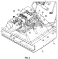
FIG. 2 illustrates a perspective view of an outflow valve assembly disposed in an interior of an aircraft in accordance with an exemplary embodiment; -
FIG. 3 illustrates a perspective view of an outflow valve assembly disposed in an interior of an aircraft in accordance with an exemplary embodiment; -
FIG. 4 illustrates a sectional side view of an outflow valve assembly disposed in an interior of an aircraft in accordance with an exemplary embodiment; -
FIG. 5 illustrates cross-sectional view a portion of an outflow valve assembly disposed in an interior of an aircraft in accordance with an exemplary embodiment; and -
FIG. 6 illustrates a method for assembling an outflow valve assembly to an aircraft in accordance with an exemplary embodiment. - The following Detailed Description is merely exemplary in nature and is not intended to limit the various embodiments or the application and uses thereof. Furthermore, there is no intention to be bound by any theory presented in the preceding background or the following detailed description.
- Various embodiments contemplated herein relate to an outflow valve assembly for an aircraft, an aircraft including an outflow valve assembly, and a method for assembling an outflow valve assembly to an aircraft. The aircraft includes a fuselage that at least partially surrounds an interior and has an opening formed therethrough to provide fluid communication between the interior and outside of the aircraft.
- In an exemplary embodiment, the outflow valve assembly is disposed in the interior about the opening and includes an outflow valve subassembly and at least one sound absorptive panel. The outflow valve subassembly includes a louver(s) that is movably disposed to at least partially cover the opening. A motor is operatively coupled to the louver to move the louver between a closed position to obstruct fluid communication through the opening and an open position to allow fluid communication through the opening between the interior and outside of the aircraft.
- The sound absorptive panel(s) is disposed adjacent to the opening to attenuate noise that is generated when the louver is in the open position, for example as air rapidly advances over the louver between the interior and outside of the aircraft. In an exemplary embodiment, advantageously by attenuating the noise proximate to its source of generation, the noise can be efficiently and effectively attenuated to prevent or substantially prevent the noise from being transmitted into other areas of the aircraft, such as, for example, the cockpit and/or cabin area(s).
-
FIGS. 1-4 illustrate various views of anoutflow valve assembly 10 arranged in aninterior 12 of anaircraft 14 in accordance with an exemplary embodiment. Theaircraft 14 includes afuselage 16 that at least partially surrounds theinterior 12 of theaircraft 14. Thefuselage 16 has an opening 18 formed therethrough for providing fluid communication between theinterior 12 and outside 20 of theaircraft 14. - As illustrated, the
outflow valve assembly 10 is disposed in theinterior 12 about theopening 18. In an exemplary embodiment, theoutflow valve assembly 10 includes an outflow valve subassembly 22 and soundabsorptive panels - In an exemplary embodiment, the outflow valve subassembly 22 includes
louvers arms motor 40. Thelouvers opening 18. As illustrated, thelouver 34 is in a closedposition 42 to obstruct a corresponding portion of theopening 18 whilelouver 32 is in anopen position 44 to allow fluid communication through a corresponding portion of the opening 18 between theinterior 12 and outside 20 of theaircraft 14. Although thelouver 32 is shown in theopen position 44 and thelouver 34 is shown in the closedposition 42, it is to be understood that thelouvers open positions louvers positions 42, theopenings 18 are completely or substantially covered and therefore, obstructed to substantially prevent any fluid communication through the opening 18 between theinterior 12 and outside 20 of theaircraft 14. Likewise, when one or more of thelouvers interior 12 and outside 20 of theaircraft 14 occurs with high speed air (e.g., traveling at about the speed of theaircraft 14 in flight) rushing over the louver(s) 32 and/or 34, thereby generating noise. - In an exemplary embodiment, the
arm 36 operatively couples themotor 40 to thelouver 32 while thearm 38 operatively couples thelouver 32 to thelouver 34 to correspondingly move thelouvers open positions arm 36 has aproximal end 46 that is coupled to themotor 40 and adistal end 48 that is pivotably coupled to alouver weldment 50 that extends upwardly from theinterior facing side 52 of thelouver 32. In response to a command signal to adjust the cabin pressure via opening one or more of thelouvers 32 and/or 34, themotor 40 responds by driving thearm 36 to move thelouver 32, which drives thearm 38 to move thelouver 34 from the closed position(s) 42 to the open position(s) 44 or vice versa. - The sound
absorptive panels opening 18 to attenuate noise that is generated when one or more of thelouvers 32 and/or 34 are in theopen position 44. As illustrated, the soundabsorptive panels absorptive wall 54 that encloses (e.g., substantially or fully surrounds) at least alower subassembly portion 56 that includes thelouvers arm 36. As such, the soundabsorptive wall 54 substantially or fully surrounds theopening 18 and thelouvers absorptive panels opening 18 and the soundabsorptive wall 54 may or may not fully enclose thelower assembly portion 56. - Referring to
FIG. 5 , in an exemplary embodiment, each of the soundabsorptive panels porous layer 58 that has an outerporous surface 60 that is disposed adjacent to and faces towards thelouvers porous layer 58 haspores 62 formed therethrough that permit molecular oscillation through theporous layer 58. Not to be limited by theory, in an exemplary embodiment, it is believed that noise is transmitted by wavelike movement of air molecules and that by permitting the oscillation of these air molecules in theporous layer 58, the noise is converted to heat energy thereby attenuating the noise. - In an exemplary embodiment, the
porous layer 58 is made of a structural material that is suitable for maintaining its integrity and enactment in this relatively harsh environment caused by the rapid flow of air over thelouvers opening 18. For example, theporous layer 58 includes or is formed of a porous metal material, such as metal felt, a perforated or micro-perforated metal layer(s), or the like. In an exemplary embodiment, theporous layer 58 includes or is formed of metal felt. - In an exemplary embodiment, the
porous layer 58 has an acoustic flow resistivity of from about 5 to about 50 rayls CGS. - As illustrated, the sound
absorptive panels intermediate layer 64 that is disposed adjacent to theporous layer 58 opposite the outer porous surface and a thirdsolid layer 66 that is disposed adjacent to theintermediate layer 64 opposite theporous layer 58. As illustrated, theintermediate layer 64 hasopenings 68 that are in fluid communication with thepores 62. Without being limited by theory, in an exemplary embodiment, it is believed that noise which passes through thepores 62 travels through theopenings 68 to thesolid layer 66 where the noise is reflected, traveling back again through theopenings 68 to theporous layer 58 for further attenuation. - In an exemplary embodiment, the
intermediate layer 64 is or includes ahoneycomb structure 70 in which each of theopenings 68 in thehoneycomb structure 70 has a diameter or maximum cross-sectional dimension of from about 0.32 to about 3.81 cm (about 0.125 to about 1.5 inches). In an exemplary embodiment, thehoneycomb structure 70 is formed of a structural material such as a metal material, e.g., metal honeycomb structure, a composite material such as a Nomex honeycomb product, or the like. In another exemplary embodiment, theintermediate layer 64 is fully or partially filled with porous fibrous or foam material. - In an exemplary embodiment, the
solid layer 66 is formed of a nonporous solid structural material, such as a fiber reinforced composite material, a metal material, or the like. In an exemplary embodiment, the soundabsorptive panels total thickness 72 from about 1.27 to about 15.24 cm (about 0.5 to about 6 inches). - Referring to
FIGS. 1-2 and5 , in an exemplary embodiment, one or more of the soundabsorptive panels outflow valve subassembly 22 in a direction (upwardly) from thelower subassembly portion 56 towards themotor 40. In an exemplary embodiment, one or more of the soundabsorptive panels angle 74 from about 45° to about 85°. -
FIG. 6 illustrates amethod 100 for assembling an outflow valve assembly to an aircraft in accordance with an exemplary embodiment. Themethod 100 includes movably disposing (STEP 102) a louver to at least partially cover an opening formed through the fuselage. - A motor is coupled (STEP 104) to the louver. The motor is configured to move the louver between a closed position to obstruct fluid communication through the opening and an open position to allow fluid communication through the opening between the interior and outside of the aircraft. A sound absorptive panel is disposed (STEP 106) adjacent to the opening to attenuate noise that is generated when the louver is in the open position.
- While at least one exemplary embodiment has been presented in the foregoing detailed description of the disclosure, it should be appreciated that a vast number of variations exist. It should also be appreciated that the exemplary embodiment or exemplary embodiments are only examples, and are not intended to limit the scope, applicability, or configuration of the disclosure in any way. Rather, the foregoing detailed description will provide those skilled in the art with a convenient road map for implementing an exemplary embodiment of the disclosure. It being understood that various changes may be made in the function and arrangement of elements described in an exemplary embodiment without departing from the scope of the disclosure as set forth in the appended claims.
Claims (14)
- An outflow valve assembly (10) for an aircraft (14) having a fuselage (16) that at least partially surrounds an interior (12), the outflow valve assembly comprising:a louver (32, 34) configured to be movably disposed to at least partially cover an opening (18) formed through the fuselage;a motor (40) coupled to the louver and configured to move the louver between a closed position (42) to obstruct fluid communication through the opening and an open position (44) to allow fluid communication through the opening between the interior and outside of the aircraft; andcharacterized by:
sound absorptive panels (24, 26, 28, 30) configured to be disposed adjacent to the opening to attenuate noise that is generated when the louver is in the open position, wherein the sound absorptive panels (24, 26, 28, 30) are coupled together to form a sound absorptive wall (54) that encloses at least a lower subassembly portion (56) of the outflow valve assembly that includes the louver (32, 34). - The outflow valve assembly of claim 1, wherein the sound absorptive panel comprises a first porous layer (58) that has an outer porous surface (60) configured to be disposed adjacent to the louver and that has pores (62) formed therethrough that permit molecular oscillation through the first porous layer.
- The outflow valve assembly of claim 2, wherein the first porous layer comprises one of metal felt and a perforated or micro-perforated metal layer.
- The outflow valve assembly of claim 2 or 3, wherein the first porous layer has an acoustic flow resistivity of from about 5 to about 50 rayls CGS.
- The outflow valve assembly of any one of claims 2-4, wherein the sound absorptive panel comprises a second layer (64) that is disposed adjacent to the first porous layer opposite the outer porous surface and that has openings (68) in fluid communication with the pores.
- The outflow valve assembly of claim 5, wherein the second layer is fully or partially filled with porous fibrous or foam materials.
- The outflow valve assembly of claim 5 or 6, wherein the second layer comprises a honeycomb structure.
- The outflow valve assembly of any one of claims 5-7, wherein the sound absorptive panel comprises a third solid layer (66) that is disposed adjacent to the second layer opposite the first porous layer.
- An aircraft comprising:a fuselage at least partially surrounding an interior and having an opening formed therethrough to provide fluid communication between the interior and outside of the aircraft; andan outflow valve assembly according to any one of claims 1-8.
- The aircraft of claim 9, further comprising an arm (36, 38) that has a first end portion (48) that is coupled to the louver and a second end portion (46) that is coupled to the motor, wherein the motor is configured to drive the arm to move the louver between the closed position and the open position.
- The aircraft of claim 10, wherein the sound absorptive panel and/or the at least one additional sound absorptive panel slant inwardly towards the outflow valve subassembly in a direction from the lower subassembly portion to the upper subassembly portion.
- The aircraft of claim 11, wherein the outflow valve subassembly further includes at least one additional louver that is movably disposed to at least partially cover the opening and at least one additional arm that directly or indirectly couples the at least one additional louver to the motor to move the at least one additional louver between the closed and open positions.
- The aircraft of claims 11 or 12, wherein the sound absorptive panel and the at least one additional sound absorptive panel of the sound absorptive wall each comprises a first porous layer that has an outer porous surface that faces towards at least the lower subassembly portion of the outflow valve subassembly and that has pores formed therethrough that permit molecular oscillation through the first porous layer.
- A method for assembling an outflow valve assembly to an aircraft having a fuselage that at least partially surrounds an interior, the method comprising the steps of:movably disposing a louver to at least partially cover an opening formed through the fuselage;coupling a motor to the louver, wherein the motor is configured to move the louver between a closed position to obstruct fluid communication through the opening and an open position to allow fluid communication through the opening between the interior and outside of the aircraft; anddisposing sound absorptive panels adjacent to the opening to attenuate noise that is generated when the louver is in the open position, wherein the sound absorptive panels are coupled together to form a sound absorptive wall that encloses at least a lower subassembly portion of the outflow valve assembly that includes the louver.
Applications Claiming Priority (1)
| Application Number | Priority Date | Filing Date | Title |
|---|---|---|---|
| US16/681,625 US11724811B2 (en) | 2019-11-12 | 2019-11-12 | Outflow valve assembly including sound absorption and aircraft including the same |
Publications (2)
| Publication Number | Publication Date |
|---|---|
| EP3822161A1 EP3822161A1 (en) | 2021-05-19 |
| EP3822161B1 true EP3822161B1 (en) | 2024-03-27 |
Family
ID=73172445
Family Applications (1)
| Application Number | Title | Priority Date | Filing Date |
|---|---|---|---|
| EP20202237.2A Active EP3822161B1 (en) | 2019-11-12 | 2020-10-16 | Outflow valve assembly including sound absorption and aircraft including the same |
Country Status (3)
| Country | Link |
|---|---|
| US (1) | US11724811B2 (en) |
| EP (1) | EP3822161B1 (en) |
| CN (1) | CN112849415B (en) |
Families Citing this family (1)
| Publication number | Priority date | Publication date | Assignee | Title |
|---|---|---|---|---|
| DE102021132863A1 (en) | 2021-12-13 | 2023-06-15 | Bachata Stiftung | Biodegradable and compostable soundproofing panel |
Family Cites Families (20)
| Publication number | Priority date | Publication date | Assignee | Title |
|---|---|---|---|---|
| US3740006A (en) * | 1971-07-29 | 1973-06-19 | Aircraft Corp | Aircraft cabin outflow valve with torque reduction and noise abatement means |
| US5834711A (en) | 1997-07-09 | 1998-11-10 | Johns Manville International, Inc. | Sound control through resonance damping |
| US6116541A (en) | 1998-02-03 | 2000-09-12 | Alliedsignal Inc. | Aircraft cabin outflow valve including aft door modified for noise suppression |
| US6668970B1 (en) * | 2001-06-06 | 2003-12-30 | Acoustic Horizons, Inc. | Acoustic attenuator |
| CN101304900A (en) * | 2005-10-25 | 2008-11-12 | 泽菲罗斯公司 | Lath structure |
| US20070101679A1 (en) | 2005-10-25 | 2007-05-10 | L&L Products, Inc. | Panel structure |
| DE102007036999A1 (en) * | 2007-08-06 | 2009-02-19 | Nord-Micro Ag & Co. Ohg | Outflow valve for an aircraft |
| DE102009051362A1 (en) * | 2009-10-30 | 2011-05-05 | Airbus Operations Gmbh | Storage compartment module with integral supply channel for optimized installation |
| US9266615B2 (en) * | 2010-01-18 | 2016-02-23 | Honeywell International Inc. | Outflow valve having flexible bellmouth and cabin pressure control system employing the same |
| US8342420B2 (en) * | 2010-10-27 | 2013-01-01 | Roberts Jr Richard W | Recyclable plastic structural articles and method of manufacture |
| US8840451B2 (en) * | 2012-01-24 | 2014-09-23 | Honeywell International Inc. | Cabin pressure outflow valve with simplified whistle eliminator |
| US20130255176A1 (en) * | 2012-03-28 | 2013-10-03 | Richard W. Roberts | In-situ foam core panel systems and method of manufacture |
| US10435159B2 (en) * | 2014-09-30 | 2019-10-08 | The Boeing Company | Cabin pressure outflow valve noise suppression devices and methods |
| US10071815B2 (en) * | 2016-03-28 | 2018-09-11 | The Boeing Company | Thrust recovery outflow valves for use with aircraft |
| US10720135B2 (en) * | 2016-07-18 | 2020-07-21 | The Boeing Company | Acoustic panels that include multi-layer facesheets |
| DE102016121366B4 (en) * | 2016-11-08 | 2021-08-12 | Airbus Operations Gmbh | CLADDING PANEL AND METHOD OF MANUFACTURING A CLADDING PANEL |
| US10752329B2 (en) * | 2017-06-26 | 2020-08-25 | The Boeing Company | Aircraft fuselage frame equipped with airbag and riser duct closure cover |
| US11485471B2 (en) | 2017-08-25 | 2022-11-01 | United States Of America As Represented By The Administrator Of Nasa | Application of leading edge serration and trailing edge foam for undercarriage wheel cavity noise reduction |
| DE102019110494A1 (en) * | 2019-04-23 | 2020-10-29 | Adler Pelzer Holding Gmbh | Absorptive needled layer composite |
| US20210086888A1 (en) * | 2019-09-24 | 2021-03-25 | Gulfstream Aerospace Corporation | Acoustic barrier assembly for use in a vehicle |
-
2019
- 2019-11-12 US US16/681,625 patent/US11724811B2/en active Active
-
2020
- 2020-10-16 EP EP20202237.2A patent/EP3822161B1/en active Active
- 2020-11-10 CN CN202011246629.6A patent/CN112849415B/en active Active
Also Published As
| Publication number | Publication date |
|---|---|
| EP3822161A1 (en) | 2021-05-19 |
| CN112849415A (en) | 2021-05-28 |
| US20210139150A1 (en) | 2021-05-13 |
| US11724811B2 (en) | 2023-08-15 |
| CN112849415B (en) | 2025-11-28 |
Similar Documents
| Publication | Publication Date | Title |
|---|---|---|
| US6267838B1 (en) | Sandwich panel made of a composite material and production method | |
| Gardonio | Review of active techniques for aerospace vibro-acoustic control | |
| CN101675226B (en) | Acoustic panels with variable acoustic characteristics | |
| EP0931309B1 (en) | Device for absorbing and/or damping sound waves | |
| EP2711922B1 (en) | Acoustic damping device for noise reduction | |
| CN102256870B (en) | Aircraft cabin panel for sound reduction | |
| US6182787B1 (en) | Rigid sandwich panel acoustic treatment | |
| RU2198798C2 (en) | Superlight multipurpose noise isolating set | |
| US7578468B2 (en) | Acoustic absorption system for an aircraft airframe | |
| EP2512925B1 (en) | Acoustically optimized air conditioning components | |
| US5861585A (en) | Aeracoustic wind tunnel turning vanes | |
| CN110997486A (en) | shield | |
| WO2007037911A1 (en) | Laminated passenger window for reduced noise transmission | |
| US5520358A (en) | Door assembly with shear layer control aperture | |
| JP7544398B2 (en) | Pressure Fluctuation Absorption Structure | |
| US11724811B2 (en) | Outflow valve assembly including sound absorption and aircraft including the same | |
| US6766985B2 (en) | Structural assembly of part of an aircraft and aircraft, particularly rotary-wing aircraft, comprising such a structural assembly | |
| US12358627B2 (en) | Acoustic air duct for environmental control system in vehicle | |
| JP2008532826A (en) | Adjustable sound absorption system for aircraft cabin | |
| US7946525B2 (en) | Material for absorbing noise in aircraft | |
| JP2020091324A (en) | Pressure fluctuation absorbing structure and thin film for suppressing pressure fluctuation | |
| Lepage et al. | Active structural acoustic control of a helicopter trim panel | |
| CN220447604U (en) | vehicle | |
| RU7391U1 (en) | CAR BODY HOOD | |
| CN220447980U (en) | Dash panel assembly and vehicle |
Legal Events
| Date | Code | Title | Description |
|---|---|---|---|
| PUAI | Public reference made under article 153(3) epc to a published international application that has entered the european phase |
Free format text: ORIGINAL CODE: 0009012 |
|
| STAA | Information on the status of an ep patent application or granted ep patent |
Free format text: STATUS: REQUEST FOR EXAMINATION WAS MADE |
|
| 17P | Request for examination filed |
Effective date: 20201016 |
|
| AK | Designated contracting states |
Kind code of ref document: A1 Designated state(s): AL AT BE BG CH CY CZ DE DK EE ES FI FR GB GR HR HU IE IS IT LI LT LU LV MC MK MT NL NO PL PT RO RS SE SI SK SM TR |
|
| STAA | Information on the status of an ep patent application or granted ep patent |
Free format text: STATUS: EXAMINATION IS IN PROGRESS |
|
| 17Q | First examination report despatched |
Effective date: 20220729 |
|
| P01 | Opt-out of the competence of the unified patent court (upc) registered |
Effective date: 20230519 |
|
| GRAP | Despatch of communication of intention to grant a patent |
Free format text: ORIGINAL CODE: EPIDOSNIGR1 |
|
| STAA | Information on the status of an ep patent application or granted ep patent |
Free format text: STATUS: GRANT OF PATENT IS INTENDED |
|
| GRAJ | Information related to disapproval of communication of intention to grant by the applicant or resumption of examination proceedings by the epo deleted |
Free format text: ORIGINAL CODE: EPIDOSDIGR1 |
|
| STAA | Information on the status of an ep patent application or granted ep patent |
Free format text: STATUS: EXAMINATION IS IN PROGRESS |
|
| GRAP | Despatch of communication of intention to grant a patent |
Free format text: ORIGINAL CODE: EPIDOSNIGR1 |
|
| INTG | Intention to grant announced |
Effective date: 20231120 |
|
| STAA | Information on the status of an ep patent application or granted ep patent |
Free format text: STATUS: GRANT OF PATENT IS INTENDED |
|
| INTC | Intention to grant announced (deleted) | ||
| INTG | Intention to grant announced |
Effective date: 20231221 |
|
| GRAS | Grant fee paid |
Free format text: ORIGINAL CODE: EPIDOSNIGR3 |
|
| GRAA | (expected) grant |
Free format text: ORIGINAL CODE: 0009210 |
|
| STAA | Information on the status of an ep patent application or granted ep patent |
Free format text: STATUS: THE PATENT HAS BEEN GRANTED |
|
| AK | Designated contracting states |
Kind code of ref document: B1 Designated state(s): AL AT BE BG CH CY CZ DE DK EE ES FI FR GB GR HR HU IE IS IT LI LT LU LV MC MK MT NL NO PL PT RO RS SE SI SK SM TR |
|
| REG | Reference to a national code |
Ref country code: GB Ref legal event code: FG4D |
|
| REG | Reference to a national code |
Ref country code: CH Ref legal event code: EP |
|
| REG | Reference to a national code |
Ref country code: DE Ref legal event code: R096 Ref document number: 602020027834 Country of ref document: DE |
|
| REG | Reference to a national code |
Ref country code: IE Ref legal event code: FG4D |
|
| PG25 | Lapsed in a contracting state [announced via postgrant information from national office to epo] |
Ref country code: LT Free format text: LAPSE BECAUSE OF FAILURE TO SUBMIT A TRANSLATION OF THE DESCRIPTION OR TO PAY THE FEE WITHIN THE PRESCRIBED TIME-LIMIT Effective date: 20240327 |
|
| REG | Reference to a national code |
Ref country code: LT Ref legal event code: MG9D |
|
| PG25 | Lapsed in a contracting state [announced via postgrant information from national office to epo] |
Ref country code: GR Free format text: LAPSE BECAUSE OF FAILURE TO SUBMIT A TRANSLATION OF THE DESCRIPTION OR TO PAY THE FEE WITHIN THE PRESCRIBED TIME-LIMIT Effective date: 20240628 |
|
| PG25 | Lapsed in a contracting state [announced via postgrant information from national office to epo] |
Ref country code: HR Free format text: LAPSE BECAUSE OF FAILURE TO SUBMIT A TRANSLATION OF THE DESCRIPTION OR TO PAY THE FEE WITHIN THE PRESCRIBED TIME-LIMIT Effective date: 20240327 Ref country code: RS Free format text: LAPSE BECAUSE OF FAILURE TO SUBMIT A TRANSLATION OF THE DESCRIPTION OR TO PAY THE FEE WITHIN THE PRESCRIBED TIME-LIMIT Effective date: 20240627 |
|
| PG25 | Lapsed in a contracting state [announced via postgrant information from national office to epo] |
Ref country code: RS Free format text: LAPSE BECAUSE OF FAILURE TO SUBMIT A TRANSLATION OF THE DESCRIPTION OR TO PAY THE FEE WITHIN THE PRESCRIBED TIME-LIMIT Effective date: 20240627 Ref country code: NO Free format text: LAPSE BECAUSE OF FAILURE TO SUBMIT A TRANSLATION OF THE DESCRIPTION OR TO PAY THE FEE WITHIN THE PRESCRIBED TIME-LIMIT Effective date: 20240627 Ref country code: LT Free format text: LAPSE BECAUSE OF FAILURE TO SUBMIT A TRANSLATION OF THE DESCRIPTION OR TO PAY THE FEE WITHIN THE PRESCRIBED TIME-LIMIT Effective date: 20240327 Ref country code: HR Free format text: LAPSE BECAUSE OF FAILURE TO SUBMIT A TRANSLATION OF THE DESCRIPTION OR TO PAY THE FEE WITHIN THE PRESCRIBED TIME-LIMIT Effective date: 20240327 Ref country code: GR Free format text: LAPSE BECAUSE OF FAILURE TO SUBMIT A TRANSLATION OF THE DESCRIPTION OR TO PAY THE FEE WITHIN THE PRESCRIBED TIME-LIMIT Effective date: 20240628 Ref country code: FI Free format text: LAPSE BECAUSE OF FAILURE TO SUBMIT A TRANSLATION OF THE DESCRIPTION OR TO PAY THE FEE WITHIN THE PRESCRIBED TIME-LIMIT Effective date: 20240327 Ref country code: BG Free format text: LAPSE BECAUSE OF FAILURE TO SUBMIT A TRANSLATION OF THE DESCRIPTION OR TO PAY THE FEE WITHIN THE PRESCRIBED TIME-LIMIT Effective date: 20240327 |
|
| REG | Reference to a national code |
Ref country code: NL Ref legal event code: MP Effective date: 20240327 |
|
| PG25 | Lapsed in a contracting state [announced via postgrant information from national office to epo] |
Ref country code: SE Free format text: LAPSE BECAUSE OF FAILURE TO SUBMIT A TRANSLATION OF THE DESCRIPTION OR TO PAY THE FEE WITHIN THE PRESCRIBED TIME-LIMIT Effective date: 20240327 Ref country code: LV Free format text: LAPSE BECAUSE OF FAILURE TO SUBMIT A TRANSLATION OF THE DESCRIPTION OR TO PAY THE FEE WITHIN THE PRESCRIBED TIME-LIMIT Effective date: 20240327 |
|
| PG25 | Lapsed in a contracting state [announced via postgrant information from national office to epo] |
Ref country code: NL Free format text: LAPSE BECAUSE OF FAILURE TO SUBMIT A TRANSLATION OF THE DESCRIPTION OR TO PAY THE FEE WITHIN THE PRESCRIBED TIME-LIMIT Effective date: 20240327 |
|
| REG | Reference to a national code |
Ref country code: AT Ref legal event code: MK05 Ref document number: 1669687 Country of ref document: AT Kind code of ref document: T Effective date: 20240327 |
|
| PG25 | Lapsed in a contracting state [announced via postgrant information from national office to epo] |
Ref country code: NL Free format text: LAPSE BECAUSE OF FAILURE TO SUBMIT A TRANSLATION OF THE DESCRIPTION OR TO PAY THE FEE WITHIN THE PRESCRIBED TIME-LIMIT Effective date: 20240327 |
|
| PG25 | Lapsed in a contracting state [announced via postgrant information from national office to epo] |
Ref country code: IS Free format text: LAPSE BECAUSE OF FAILURE TO SUBMIT A TRANSLATION OF THE DESCRIPTION OR TO PAY THE FEE WITHIN THE PRESCRIBED TIME-LIMIT Effective date: 20240727 |
|
| PG25 | Lapsed in a contracting state [announced via postgrant information from national office to epo] |
Ref country code: SM Free format text: LAPSE BECAUSE OF FAILURE TO SUBMIT A TRANSLATION OF THE DESCRIPTION OR TO PAY THE FEE WITHIN THE PRESCRIBED TIME-LIMIT Effective date: 20240327 Ref country code: PT Free format text: LAPSE BECAUSE OF FAILURE TO SUBMIT A TRANSLATION OF THE DESCRIPTION OR TO PAY THE FEE WITHIN THE PRESCRIBED TIME-LIMIT Effective date: 20240729 |
|
| PG25 | Lapsed in a contracting state [announced via postgrant information from national office to epo] |
Ref country code: ES Free format text: LAPSE BECAUSE OF FAILURE TO SUBMIT A TRANSLATION OF THE DESCRIPTION OR TO PAY THE FEE WITHIN THE PRESCRIBED TIME-LIMIT Effective date: 20240327 |
|
| PG25 | Lapsed in a contracting state [announced via postgrant information from national office to epo] |
Ref country code: EE Free format text: LAPSE BECAUSE OF FAILURE TO SUBMIT A TRANSLATION OF THE DESCRIPTION OR TO PAY THE FEE WITHIN THE PRESCRIBED TIME-LIMIT Effective date: 20240327 Ref country code: CZ Free format text: LAPSE BECAUSE OF FAILURE TO SUBMIT A TRANSLATION OF THE DESCRIPTION OR TO PAY THE FEE WITHIN THE PRESCRIBED TIME-LIMIT Effective date: 20240327 |
|
| PG25 | Lapsed in a contracting state [announced via postgrant information from national office to epo] |
Ref country code: AT Free format text: LAPSE BECAUSE OF FAILURE TO SUBMIT A TRANSLATION OF THE DESCRIPTION OR TO PAY THE FEE WITHIN THE PRESCRIBED TIME-LIMIT Effective date: 20240327 |
|
| PG25 | Lapsed in a contracting state [announced via postgrant information from national office to epo] |
Ref country code: PL Free format text: LAPSE BECAUSE OF FAILURE TO SUBMIT A TRANSLATION OF THE DESCRIPTION OR TO PAY THE FEE WITHIN THE PRESCRIBED TIME-LIMIT Effective date: 20240327 |
|
| PG25 | Lapsed in a contracting state [announced via postgrant information from national office to epo] |
Ref country code: SK Free format text: LAPSE BECAUSE OF FAILURE TO SUBMIT A TRANSLATION OF THE DESCRIPTION OR TO PAY THE FEE WITHIN THE PRESCRIBED TIME-LIMIT Effective date: 20240327 |
|
| PG25 | Lapsed in a contracting state [announced via postgrant information from national office to epo] |
Ref country code: SM Free format text: LAPSE BECAUSE OF FAILURE TO SUBMIT A TRANSLATION OF THE DESCRIPTION OR TO PAY THE FEE WITHIN THE PRESCRIBED TIME-LIMIT Effective date: 20240327 Ref country code: SK Free format text: LAPSE BECAUSE OF FAILURE TO SUBMIT A TRANSLATION OF THE DESCRIPTION OR TO PAY THE FEE WITHIN THE PRESCRIBED TIME-LIMIT Effective date: 20240327 Ref country code: RO Free format text: LAPSE BECAUSE OF FAILURE TO SUBMIT A TRANSLATION OF THE DESCRIPTION OR TO PAY THE FEE WITHIN THE PRESCRIBED TIME-LIMIT Effective date: 20240327 Ref country code: PT Free format text: LAPSE BECAUSE OF FAILURE TO SUBMIT A TRANSLATION OF THE DESCRIPTION OR TO PAY THE FEE WITHIN THE PRESCRIBED TIME-LIMIT Effective date: 20240729 Ref country code: PL Free format text: LAPSE BECAUSE OF FAILURE TO SUBMIT A TRANSLATION OF THE DESCRIPTION OR TO PAY THE FEE WITHIN THE PRESCRIBED TIME-LIMIT Effective date: 20240327 Ref country code: IS Free format text: LAPSE BECAUSE OF FAILURE TO SUBMIT A TRANSLATION OF THE DESCRIPTION OR TO PAY THE FEE WITHIN THE PRESCRIBED TIME-LIMIT Effective date: 20240727 Ref country code: ES Free format text: LAPSE BECAUSE OF FAILURE TO SUBMIT A TRANSLATION OF THE DESCRIPTION OR TO PAY THE FEE WITHIN THE PRESCRIBED TIME-LIMIT Effective date: 20240327 Ref country code: EE Free format text: LAPSE BECAUSE OF FAILURE TO SUBMIT A TRANSLATION OF THE DESCRIPTION OR TO PAY THE FEE WITHIN THE PRESCRIBED TIME-LIMIT Effective date: 20240327 Ref country code: CZ Free format text: LAPSE BECAUSE OF FAILURE TO SUBMIT A TRANSLATION OF THE DESCRIPTION OR TO PAY THE FEE WITHIN THE PRESCRIBED TIME-LIMIT Effective date: 20240327 Ref country code: AT Free format text: LAPSE BECAUSE OF FAILURE TO SUBMIT A TRANSLATION OF THE DESCRIPTION OR TO PAY THE FEE WITHIN THE PRESCRIBED TIME-LIMIT Effective date: 20240327 |
|
| PG25 | Lapsed in a contracting state [announced via postgrant information from national office to epo] |
Ref country code: IT Free format text: LAPSE BECAUSE OF FAILURE TO SUBMIT A TRANSLATION OF THE DESCRIPTION OR TO PAY THE FEE WITHIN THE PRESCRIBED TIME-LIMIT Effective date: 20240327 |
|
| PG25 | Lapsed in a contracting state [announced via postgrant information from national office to epo] |
Ref country code: IT Free format text: LAPSE BECAUSE OF FAILURE TO SUBMIT A TRANSLATION OF THE DESCRIPTION OR TO PAY THE FEE WITHIN THE PRESCRIBED TIME-LIMIT Effective date: 20240327 |
|
| REG | Reference to a national code |
Ref country code: DE Ref legal event code: R097 Ref document number: 602020027834 Country of ref document: DE |
|
| PG25 | Lapsed in a contracting state [announced via postgrant information from national office to epo] |
Ref country code: DK Free format text: LAPSE BECAUSE OF FAILURE TO SUBMIT A TRANSLATION OF THE DESCRIPTION OR TO PAY THE FEE WITHIN THE PRESCRIBED TIME-LIMIT Effective date: 20240327 |
|
| PG25 | Lapsed in a contracting state [announced via postgrant information from national office to epo] |
Ref country code: DK Free format text: LAPSE BECAUSE OF FAILURE TO SUBMIT A TRANSLATION OF THE DESCRIPTION OR TO PAY THE FEE WITHIN THE PRESCRIBED TIME-LIMIT Effective date: 20240327 |
|
| PLBE | No opposition filed within time limit |
Free format text: ORIGINAL CODE: 0009261 |
|
| STAA | Information on the status of an ep patent application or granted ep patent |
Free format text: STATUS: NO OPPOSITION FILED WITHIN TIME LIMIT |
|
| 26N | No opposition filed |
Effective date: 20250103 |
|
| PG25 | Lapsed in a contracting state [announced via postgrant information from national office to epo] |
Ref country code: SI Free format text: LAPSE BECAUSE OF FAILURE TO SUBMIT A TRANSLATION OF THE DESCRIPTION OR TO PAY THE FEE WITHIN THE PRESCRIBED TIME-LIMIT Effective date: 20240327 |
|
| REG | Reference to a national code |
Ref country code: CH Ref legal event code: PL |
|
| GBPC | Gb: european patent ceased through non-payment of renewal fee |
Effective date: 20241016 |
|
| PG25 | Lapsed in a contracting state [announced via postgrant information from national office to epo] |
Ref country code: MC Free format text: LAPSE BECAUSE OF FAILURE TO SUBMIT A TRANSLATION OF THE DESCRIPTION OR TO PAY THE FEE WITHIN THE PRESCRIBED TIME-LIMIT Effective date: 20240327 |
|
| PG25 | Lapsed in a contracting state [announced via postgrant information from national office to epo] |
Ref country code: GB Free format text: LAPSE BECAUSE OF NON-PAYMENT OF DUE FEES Effective date: 20241016 |
|
| PG25 | Lapsed in a contracting state [announced via postgrant information from national office to epo] |
Ref country code: BE Free format text: LAPSE BECAUSE OF NON-PAYMENT OF DUE FEES Effective date: 20241031 Ref country code: LU Free format text: LAPSE BECAUSE OF NON-PAYMENT OF DUE FEES Effective date: 20241016 |
|
| PG25 | Lapsed in a contracting state [announced via postgrant information from national office to epo] |
Ref country code: FR Free format text: LAPSE BECAUSE OF NON-PAYMENT OF DUE FEES Effective date: 20241031 |
|
| PG25 | Lapsed in a contracting state [announced via postgrant information from national office to epo] |
Ref country code: CH Free format text: LAPSE BECAUSE OF NON-PAYMENT OF DUE FEES Effective date: 20241031 |
|
| REG | Reference to a national code |
Ref country code: BE Ref legal event code: MM Effective date: 20241031 |
|
| PG25 | Lapsed in a contracting state [announced via postgrant information from national office to epo] |
Ref country code: IE Free format text: LAPSE BECAUSE OF NON-PAYMENT OF DUE FEES Effective date: 20241016 |
|
| PGFP | Annual fee paid to national office [announced via postgrant information from national office to epo] |
Ref country code: DE Payment date: 20251029 Year of fee payment: 6 |
|
| PG25 | Lapsed in a contracting state [announced via postgrant information from national office to epo] |
Ref country code: CY Free format text: LAPSE BECAUSE OF FAILURE TO SUBMIT A TRANSLATION OF THE DESCRIPTION OR TO PAY THE FEE WITHIN THE PRESCRIBED TIME-LIMIT; INVALID AB INITIO Effective date: 20201016 |
|
| PG25 | Lapsed in a contracting state [announced via postgrant information from national office to epo] |
Ref country code: HU Free format text: LAPSE BECAUSE OF FAILURE TO SUBMIT A TRANSLATION OF THE DESCRIPTION OR TO PAY THE FEE WITHIN THE PRESCRIBED TIME-LIMIT; INVALID AB INITIO Effective date: 20201016 |