EP3822134A1 - Brake system for a motor vehicle and trailer control module - Google Patents
Brake system for a motor vehicle and trailer control module Download PDFInfo
- Publication number
- EP3822134A1 EP3822134A1 EP19209865.5A EP19209865A EP3822134A1 EP 3822134 A1 EP3822134 A1 EP 3822134A1 EP 19209865 A EP19209865 A EP 19209865A EP 3822134 A1 EP3822134 A1 EP 3822134A1
- Authority
- EP
- European Patent Office
- Prior art keywords
- trailer
- control
- brake
- control module
- pressure
- Prior art date
- Legal status (The legal status is an assumption and is not a legal conclusion. Google has not performed a legal analysis and makes no representation as to the accuracy of the status listed.)
- Granted
Links
- 238000004891 communication Methods 0.000 claims description 4
- 230000009977 dual effect Effects 0.000 description 6
- 241000711508 Turkey coronavirus Species 0.000 description 2
- 230000005662 electromechanics Effects 0.000 description 2
- 238000000034 method Methods 0.000 description 2
- 230000008878 coupling Effects 0.000 description 1
- 238000010168 coupling process Methods 0.000 description 1
- 238000005859 coupling reaction Methods 0.000 description 1
- 230000001419 dependent effect Effects 0.000 description 1
- 238000013461 design Methods 0.000 description 1
- 238000011161 development Methods 0.000 description 1
- 230000018109 developmental process Effects 0.000 description 1
- 230000000694 effects Effects 0.000 description 1
- 238000005265 energy consumption Methods 0.000 description 1
- 238000012423 maintenance Methods 0.000 description 1
Images
Classifications
-
- B—PERFORMING OPERATIONS; TRANSPORTING
- B60—VEHICLES IN GENERAL
- B60T—VEHICLE BRAKE CONTROL SYSTEMS OR PARTS THEREOF; BRAKE CONTROL SYSTEMS OR PARTS THEREOF, IN GENERAL; ARRANGEMENT OF BRAKING ELEMENTS ON VEHICLES IN GENERAL; PORTABLE DEVICES FOR PREVENTING UNWANTED MOVEMENT OF VEHICLES; VEHICLE MODIFICATIONS TO FACILITATE COOLING OF BRAKES
- B60T13/00—Transmitting braking action from initiating means to ultimate brake actuator with power assistance or drive; Brake systems incorporating such transmitting means, e.g. air-pressure brake systems
- B60T13/10—Transmitting braking action from initiating means to ultimate brake actuator with power assistance or drive; Brake systems incorporating such transmitting means, e.g. air-pressure brake systems with fluid assistance, drive, or release
- B60T13/24—Transmitting braking action from initiating means to ultimate brake actuator with power assistance or drive; Brake systems incorporating such transmitting means, e.g. air-pressure brake systems with fluid assistance, drive, or release the fluid being gaseous
- B60T13/26—Compressed-air systems
- B60T13/261—Compressed-air systems systems with both indirect application and application by springs or weights and released by compressed air
- B60T13/263—Compressed-air systems systems with both indirect application and application by springs or weights and released by compressed air specially adapted for coupling with dependent systems, e.g. tractor-trailer systems
-
- B—PERFORMING OPERATIONS; TRANSPORTING
- B60—VEHICLES IN GENERAL
- B60T—VEHICLE BRAKE CONTROL SYSTEMS OR PARTS THEREOF; BRAKE CONTROL SYSTEMS OR PARTS THEREOF, IN GENERAL; ARRANGEMENT OF BRAKING ELEMENTS ON VEHICLES IN GENERAL; PORTABLE DEVICES FOR PREVENTING UNWANTED MOVEMENT OF VEHICLES; VEHICLE MODIFICATIONS TO FACILITATE COOLING OF BRAKES
- B60T13/00—Transmitting braking action from initiating means to ultimate brake actuator with power assistance or drive; Brake systems incorporating such transmitting means, e.g. air-pressure brake systems
- B60T13/10—Transmitting braking action from initiating means to ultimate brake actuator with power assistance or drive; Brake systems incorporating such transmitting means, e.g. air-pressure brake systems with fluid assistance, drive, or release
- B60T13/66—Electrical control in fluid-pressure brake systems
- B60T13/68—Electrical control in fluid-pressure brake systems by electrically-controlled valves
- B60T13/683—Electrical control in fluid-pressure brake systems by electrically-controlled valves in pneumatic systems or parts thereof
-
- B—PERFORMING OPERATIONS; TRANSPORTING
- B60—VEHICLES IN GENERAL
- B60T—VEHICLE BRAKE CONTROL SYSTEMS OR PARTS THEREOF; BRAKE CONTROL SYSTEMS OR PARTS THEREOF, IN GENERAL; ARRANGEMENT OF BRAKING ELEMENTS ON VEHICLES IN GENERAL; PORTABLE DEVICES FOR PREVENTING UNWANTED MOVEMENT OF VEHICLES; VEHICLE MODIFICATIONS TO FACILITATE COOLING OF BRAKES
- B60T13/00—Transmitting braking action from initiating means to ultimate brake actuator with power assistance or drive; Brake systems incorporating such transmitting means, e.g. air-pressure brake systems
- B60T13/10—Transmitting braking action from initiating means to ultimate brake actuator with power assistance or drive; Brake systems incorporating such transmitting means, e.g. air-pressure brake systems with fluid assistance, drive, or release
- B60T13/24—Transmitting braking action from initiating means to ultimate brake actuator with power assistance or drive; Brake systems incorporating such transmitting means, e.g. air-pressure brake systems with fluid assistance, drive, or release the fluid being gaseous
- B60T13/26—Compressed-air systems
- B60T13/36—Compressed-air systems direct, i.e. brakes applied directly by compressed air
-
- B—PERFORMING OPERATIONS; TRANSPORTING
- B60—VEHICLES IN GENERAL
- B60T—VEHICLE BRAKE CONTROL SYSTEMS OR PARTS THEREOF; BRAKE CONTROL SYSTEMS OR PARTS THEREOF, IN GENERAL; ARRANGEMENT OF BRAKING ELEMENTS ON VEHICLES IN GENERAL; PORTABLE DEVICES FOR PREVENTING UNWANTED MOVEMENT OF VEHICLES; VEHICLE MODIFICATIONS TO FACILITATE COOLING OF BRAKES
- B60T17/00—Component parts, details, or accessories of power brake systems not covered by groups B60T8/00, B60T13/00 or B60T15/00, or presenting other characteristic features
- B60T17/18—Safety devices; Monitoring
- B60T17/22—Devices for monitoring or checking brake systems; Signal devices
- B60T17/221—Procedure or apparatus for checking or keeping in a correct functioning condition of brake systems
-
- B—PERFORMING OPERATIONS; TRANSPORTING
- B60—VEHICLES IN GENERAL
- B60T—VEHICLE BRAKE CONTROL SYSTEMS OR PARTS THEREOF; BRAKE CONTROL SYSTEMS OR PARTS THEREOF, IN GENERAL; ARRANGEMENT OF BRAKING ELEMENTS ON VEHICLES IN GENERAL; PORTABLE DEVICES FOR PREVENTING UNWANTED MOVEMENT OF VEHICLES; VEHICLE MODIFICATIONS TO FACILITATE COOLING OF BRAKES
- B60T2270/00—Further aspects of brake control systems not otherwise provided for
- B60T2270/40—Failsafe aspects of brake control systems
- B60T2270/402—Back-up
-
- B—PERFORMING OPERATIONS; TRANSPORTING
- B60—VEHICLES IN GENERAL
- B60T—VEHICLE BRAKE CONTROL SYSTEMS OR PARTS THEREOF; BRAKE CONTROL SYSTEMS OR PARTS THEREOF, IN GENERAL; ARRANGEMENT OF BRAKING ELEMENTS ON VEHICLES IN GENERAL; PORTABLE DEVICES FOR PREVENTING UNWANTED MOVEMENT OF VEHICLES; VEHICLE MODIFICATIONS TO FACILITATE COOLING OF BRAKES
- B60T2270/00—Further aspects of brake control systems not otherwise provided for
- B60T2270/40—Failsafe aspects of brake control systems
- B60T2270/413—Plausibility monitoring, cross check, redundancy
-
- B—PERFORMING OPERATIONS; TRANSPORTING
- B60—VEHICLES IN GENERAL
- B60T—VEHICLE BRAKE CONTROL SYSTEMS OR PARTS THEREOF; BRAKE CONTROL SYSTEMS OR PARTS THEREOF, IN GENERAL; ARRANGEMENT OF BRAKING ELEMENTS ON VEHICLES IN GENERAL; PORTABLE DEVICES FOR PREVENTING UNWANTED MOVEMENT OF VEHICLES; VEHICLE MODIFICATIONS TO FACILITATE COOLING OF BRAKES
- B60T2270/00—Further aspects of brake control systems not otherwise provided for
- B60T2270/84—Driver circuits for actuating motor, valve and the like
-
- B—PERFORMING OPERATIONS; TRANSPORTING
- B60—VEHICLES IN GENERAL
- B60Y—INDEXING SCHEME RELATING TO ASPECTS CROSS-CUTTING VEHICLE TECHNOLOGY
- B60Y2200/00—Type of vehicle
- B60Y2200/10—Road Vehicles
- B60Y2200/14—Trucks; Load vehicles, Busses
- B60Y2200/147—Trailers, e.g. full trailers or caravans
-
- B—PERFORMING OPERATIONS; TRANSPORTING
- B60—VEHICLES IN GENERAL
- B60Y—INDEXING SCHEME RELATING TO ASPECTS CROSS-CUTTING VEHICLE TECHNOLOGY
- B60Y2400/00—Special features of vehicle units
- B60Y2400/81—Braking systems
Definitions
- the invention relates to a brake system for a motor vehicle to be equipped with a trailer, comprising a trailer control module, and to a trailer control module for such a brake system.
- brake systems of commercial vehicles are operated with compressed air, in both, motor vehicles and their trailers.
- the interface between motor vehicle and trailer is standardized with appropriate compressed air connections.
- the brakes of the trailer are controlled by trailer control valves (TCV) or a so-called trailer control module (TCM), which is/are positioned in the motor vehicle and therefore forms/form part of its brake system.
- TCV trailer control valves
- TCM trailer control module
- the TCVs/TCM comprise at least two independent control input terminals that are able to receive inputs from an electronic control unit (ECU) that processes the signals of a service brake, which is operated by the operator of the vehicle, if there is a need to slow the vehicle down.
- ECU electronice control unit
- TCMs comprise an inverted pneumatic control input coming from the parking brake, a compressed air supply inlet and two coupling head outputs (pneumatic outlets), one for the air supply of the trailer and one for the pneumatic control line for the trailer brakes.
- a digital communication line between the motor vehicle and the trailer in the form of a 24V CAN bus, standardized according to ISO 11992.
- the description of an internal design of a state-of-the-art TCM is provided for example in the document EP1127764 .
- a TCM according to the state of the art disclosed in the document is provided with three different solenoid valves, with which in combination of a relay valve allows to adjust the brake pressure for the braking units of a trailer.
- a trailer control module for a brake system of a motor vehicle is configured to provide a preset brake control outlet pressure to a pneumatic trailer brake system and comprises at least two electrical terminals, which are configured to receive two independent but redundant electrical control input signals, which comprise the signal for the preset brake control outlet pressure. It further comprises at least one pneumatic inlet terminal, which is configured to receive constant pressure from an air pressure source, at least one valve, configured to adjust the constant air pressure from the air pressure source to the preset break outlet pressure, at least one brake supply pressure terminal, configured to provide the brake supply outlet pressure to the pneumatic brake system of the trailer and at least one brake control pressure terminal, configured to provide the preset brake control outlet pressure to the pneumatic brake system of the trailer.
- the trailer control module comprises at least two control solenoid groups, each including a load- and an exhaust valve and each group allowing to control the brake control outlet pressure by itself and independently from one another via its own control channel.
- Each solenoid group is provided with its own independent but redundant signal from the two different brake ECUs.
- the control channel is formed by the technical elements like valves (relay valve) that define the brake control outlet pressure.
- a further advantageous embodiment of the TCM according to the invention comprises a normally opened exhaust valve (for example as a solenoid) for normally not parked trailer control for each control channel of its relay valve.
- a normally not parked trailer is a trailer, whose parking brakes are inactive, while the vehicle it is attached to, has its parking brakes active as the brakes of the vehicle alone should be able to hold both the vehicle and the trailer in parking position when they are active.
- This has the advantage that a combination parking stability is not depending on the trailer parking brakes (which are not always spring brake based) but the tractor parking brakes only (which are always spring brake based).
- a normally parked trailer is a trailer, whose parking brakes are active, while the vehicle it is attached to, has its parking brakes also active.
- the TCM comprises a normally closed exhaust valve (for example as a solenoid) and a feedback orifice to achieve a bistable parking brake operation for normally parked trailer control for each control channel of its relay valve.
- the TCM comprises a normally closed exhaust valve and a feedback orifice for normally parked trailer control for one control channel and a normally opened exhaust valve for normally not parked trailer control for another control channel of its relay valve.
- the TCM comprises normally closed exhaust valves and a feedback orifice for normally parked trailer control for both control channels.
- the trailer control module comprises normally opened exhaust valves for normally not parked trailer control for the control channel.
- the TCM comprises at least two independent pressure sensors, configured to measure the brake control outlet pressure of the trailer. In this way the correct functionality of the brake system and the TCM can easily be controlled and adjusted by the ECUs of the motor vehicle brake system if necessary.
- the trailer control module comprises a hold back valve to trigger the automatic trailer emergency braking at an unexpected disconnection between the vehicle and the trailer. If an unexpected disconnection during operation (driving) occurs, the legislation requires an emergency braking function of the trailer. This can be realized by a hold back valve, which provides the supplied pressure directly to a brake supply terminal.
- a motor vehicle brake system comprises, at least two independent brake control units (ECUs) which are configured to provide the TCM with at least two independent but redundant electronic signals comprising the signal for the preset brake control outlet pressure. It further comprises a trailer control module according to the invention and an air pressure source, configured to supply a constant pneumatic pressure to the brakes of the trailer.
- ECUs independent brake control units
- an air pressure source configured to supply a constant pneumatic pressure to the brakes of the trailer.
- the motor vehicle brake system further comprises a communication line between the trailer and the brake control units, wherein a multiplexer is configured to connect the trailer to either one or the other brake control unit, so that only one brake control unit is connected with the trailer at a time.
- Fig. 1 shows a schematic layout of the motor vehicle brake system according to the invention.
- the brake system according to the invention is powered by at least two independent electric energy sources 40a, 40b and controlled by at least two independent electronic control units 10a, 10b (ECU).
- the foot brake sensor 30 is operated by the operator of the motor vehicle in case that braking is necessary.
- the signal is provided at both, the first ECU 10a and the second ECU 10b.
- a parking brake control 31 is connected to both ECUs 10a, 10b. Embodiments, where the parking brake control is only connected to one ECU are also possible.
- Both, the parking brake control 31 and the foot brake sensor 30 are connected with the ECUs 10a, 10b via analogous electrical lines 90, which could also be digital in other embodiments of the invention.
- the first ECU 10a is further connected with the second ECU 10b via a digital electric signal line 80.
- Both ECUs 10a, 10b are capable of controlling four wheel brake units 50a, 50b, 50c, 50d (which could be more or less in other embodiments of the invention) via a digital electrical line 80, so that both ECUs 10a, 10b are capable of commanding the wheel brake units 50a-50d through at least two independent communication lines.
- the wheel brake units 50a, 50b as well as the first ECU 10a are powered by the first electric energy source 40a, while the wheel brake units 50c, 50d and the second ECU 10b are powered by the second electric energy source 40b.
- both ECUs 10a, 10b send redundant electric signals via analogous electric lines 90, which could also be digital in other embodiments, to a trailer control module (TCM) 20, which provides a braking outlet pressure to the trailer brake system.
- TCM 20 is further connected to an air pressure source 60, which provides the TCM 20 with a constant pneumatic pressure.
- the TCM 60 is only provided with electric signals to adjust the brake pressure for the trailer.
- a multiplexer 70 is connected with the trailer via a standardized CAN-bus according to ISO 11992 known from the state of the art and either passes the signals from the first ECU 10a or of the second ECU 10b to the trailer. It can be either physical (by an active switch) or functional (by e.g. an interconnected bus to both brake control units and a master is commanding and a slave is listening).
- the operator (driver) of the motor vehicle operates the foot brake sensor 30 for normal service brake needs and the parking brake control 31, if a movement of the vehicle in standstill is to be prevented.
- the electric signal is passed to both ECUs 10a, 10b, where a necessary braking force is calculated, according to which the ECUs 10a, 10b control the wheel brake units 50a, 50b, 50c, 50d of the motor vehicle via the corresponding digital electric signal lines 80.
- the information of a brake pressure, which needs to be applied to the pneumatic brake system of the trailer is passed via electric signals to the TCM 20 via the analogous electric line 90.
- the TCM adjusts the demanded brake pressure and provides it to the brake system of the trailer. Further, information of either one of the ECUs 10a, 10b is provided to the trailer according to the position of the multiplexer 70 via the CAN-bus.
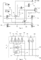
- Fig. 2 shows a schematic layout of the architecture of a TCM according to an embodiment of the invention.
- the pneumatic pressure of the air pressure source 60 is provided at an air pressure source inlet A.
- the air pressure source inlet A is connected via an air pressure source pressure line 23 with a hold back valve 25 and two solenoid valves 21b and 21c. Both of them are in the following also referred to as load valves 21b, 21c and are in a normally closed state.
- load valves 21b, 21c At each side of the load valves 21b, 21c, two further solenoid valves 21a, 21d are positioned, which are also referred to as exhaust valves 21a, 21d, the exhaust valve 21a being in a normally opened state and the exhaust valve 21d being in a normally closed state.
- All of the four solenoid valves 21a-21d are controlled by the electric signals of the two ECUs 10a, 10b of the brake system of the motor vehicle.
- the solenoid valves 21a, 21b form one group controlled by the first ECU 10a and the solenoid valves 21c, 21d form a second group controlled by the second ECU 10b.
- a control pressure line 24 to the hold back valve 25 and to the corresponding exhaust valve 21a, 21d of each group is formed. Further the control pressure lines 24 from the load valves 21b, 21c also connect a dual channel relay valve 26 and an orifice 27. A further pressure line, referred to as exhaust pressure line 22, leads from the outlets of the exhaust valves 21a, 21d and the dual channel relay valve 26 to an exhaust outlet terminal B, where pressure, which is not needed anymore in the system, can be released to the atmosphere.
- one outlet of the hold back valve 25 is connected to one inlet of the dual channel relay valve 26 via a brake supply pressure outlet 29a, which also leads to a brake supply pressure terminal C, which is a pneumatic outlet and connected to the air pressure tanks of the trailer.
- a brake supply pressure terminal C which is a pneumatic outlet and connected to the air pressure tanks of the trailer.
- one outlet of the dual channel relay valve 26 is connected to the exhaust outlet terminal B.
- Another outlet of the dual channel relay valve 26 is connected to a brake control pressure terminal D by a brake control pressure outlet 29b.
- the brake control pressure terminal D is a second pneumatic outlet and provides a trailer brake control pressure signal to the trailer.
- the pressure in the brake control pressure outlet 29b is measured by two pressure sensors 28a, 28b, which are permanently connected via an analogue or digital line with both ECUs 10a, 10b.
- the pressure provided by the air pressure source 60 at the air pressure source inlet A is provided directly at the brake supply pressure terminal C under normal operation and switches to its orifice position in case of an unexpected trailer disconnection to introduce an emergency braking to the trailer.
Abstract
Description
- The invention relates to a brake system for a motor vehicle to be equipped with a trailer, comprising a trailer control module, and to a trailer control module for such a brake system.
- Nowadays, brake systems of commercial vehicles are operated with compressed air, in both, motor vehicles and their trailers. In the brake system, the interface between motor vehicle and trailer is standardized with appropriate compressed air connections.
- However, the electrification of brake systems in modern vehicles is an attractive way to reduce auxiliary energy consumption, space need and noise emissions. As trailers usually have a longer life cycle, and hence could have many different owners throughout their life cycles, a solution for the electrification of brake systems of motor vehicles should be compatible with existing brake systems of trailers, which usually still work with pneumatic brakes, in order to be able to continue using existing trailers with pneumatic brakes. Therefore, a solution for the electro-mechanic brake system that is used preferably in modern motor vehicles is required, which is able to control the pneumatic brake system of a trailer.
- In state of the art brake systems for motor vehicles and trailers, for example described in document
DE10310235A1 , the brakes of the trailer are controlled by trailer control valves (TCV) or a so-called trailer control module (TCM), which is/are positioned in the motor vehicle and therefore forms/form part of its brake system. In order to be able to provide brake pressure even if one brake circuit signal does not work, a redundant independent signal is necessary. Hence, the TCVs/TCM comprise at least two independent control input terminals that are able to receive inputs from an electronic control unit (ECU) that processes the signals of a service brake, which is operated by the operator of the vehicle, if there is a need to slow the vehicle down. Those inputs from the ECU to the TCV/TCMs are either both pneumatic in case of the use of TCVs or one is pneumatic and one is electric from an electric control line in case of the use of a TCM. Moreover, TCMs comprise an inverted pneumatic control input coming from the parking brake, a compressed air supply inlet and two coupling head outputs (pneumatic outlets), one for the air supply of the trailer and one for the pneumatic control line for the trailer brakes. Furthermore, there is optionally a digital communication line between the motor vehicle and the trailer in the form of a 24V CAN bus, standardized according to ISO 11992. The description of an internal design of a state-of-the-art TCM is provided for example in the documentEP1127764 . A TCM according to the state of the art disclosed in the document is provided with three different solenoid valves, with which in combination of a relay valve allows to adjust the brake pressure for the braking units of a trailer. - With modern electro-mechanic brake systems of motor vehicles being able to provide only electrical outputs instead of at least one pneumatic output, the need for new TCMs arises. Therefore, it is the objective of the present invention to provide a TCM and a brake system in a motor vehicle with a TCM that are compatible with the pneumatic state-of-the-art trailer brake systems described above.
- Such a TCM and a brake system for a motor vehicle with the TCM is provided by the subject-matters of the independent claims. Further developments of the invention with advantageous effects are provided by the dependent claims.
- A trailer control module for a brake system of a motor vehicle according to the present invention is configured to provide a preset brake control outlet pressure to a pneumatic trailer brake system and comprises at least two electrical terminals, which are configured to receive two independent but redundant electrical control input signals, which comprise the signal for the preset brake control outlet pressure. It further comprises at least one pneumatic inlet terminal, which is configured to receive constant pressure from an air pressure source, at least one valve, configured to adjust the constant air pressure from the air pressure source to the preset break outlet pressure, at least one brake supply pressure terminal, configured to provide the brake supply outlet pressure to the pneumatic brake system of the trailer and at least one brake control pressure terminal, configured to provide the preset brake control outlet pressure to the pneumatic brake system of the trailer.
- In an advantageous embodiment of the invention the trailer control module comprises at least two control solenoid groups, each including a load- and an exhaust valve and each group allowing to control the brake control outlet pressure by itself and independently from one another via its own control channel. Each solenoid group is provided with its own independent but redundant signal from the two different brake ECUs. Hence, in order for the TCM to be able to process both different but redundant electric signals independently from each other and to satisfy the existing safety requirements, it also needs internally two separate pressure control channels in which the pneumatic signals can be processed to the brake control outlet pressure. Thus, the control channel is formed by the technical elements like valves (relay valve) that define the brake control outlet pressure. An advantage of the use of solenoids in the TCM is that solenoids are well known in the state of the art, easy to handle also in terms of maintenance and don't need a lot of energy to be operated.
- A further advantageous embodiment of the TCM according to the invention comprises a normally opened exhaust valve (for example as a solenoid) for normally not parked trailer control for each control channel of its relay valve. In the context of this application, a normally not parked trailer is a trailer, whose parking brakes are inactive, while the vehicle it is attached to, has its parking brakes active as the brakes of the vehicle alone should be able to hold both the vehicle and the trailer in parking position when they are active. This has the advantage that a combination parking stability is not depending on the trailer parking brakes (which are not always spring brake based) but the tractor parking brakes only (which are always spring brake based). According to this definition, a normally parked trailer is a trailer, whose parking brakes are active, while the vehicle it is attached to, has its parking brakes also active.
- In a further advantageous embodiment of the invention, the TCM comprises a normally closed exhaust valve (for example as a solenoid) and a feedback orifice to achieve a bistable parking brake operation for normally parked trailer control for each control channel of its relay valve.
- In another advantageous embodiment of the invention the TCM comprises a normally closed exhaust valve and a feedback orifice for normally parked trailer control for one control channel and a normally opened exhaust valve for normally not parked trailer control for another control channel of its relay valve.
- In another advantageous embodiment of the invention the TCM comprises normally closed exhaust valves and a feedback orifice for normally parked trailer control for both control channels.
- In another advantageous embodiment of the invention the trailer control module comprises normally opened exhaust valves for normally not parked trailer control for the control channel.
- In yet another advantageous embodiment of the invention the TCM comprises at least two independent pressure sensors, configured to measure the brake control outlet pressure of the trailer. In this way the correct functionality of the brake system and the TCM can easily be controlled and adjusted by the ECUs of the motor vehicle brake system if necessary.
- In a further advantageous embodiment of the invention, the trailer control module comprises a hold back valve to trigger the automatic trailer emergency braking at an unexpected disconnection between the vehicle and the trailer. If an unexpected disconnection during operation (driving) occurs, the legislation requires an emergency braking function of the trailer. This can be realized by a hold back valve, which provides the supplied pressure directly to a brake supply terminal.
- A motor vehicle brake system according to the invention comprises, at least two independent brake control units (ECUs) which are configured to provide the TCM with at least two independent but redundant electronic signals comprising the signal for the preset brake control outlet pressure. It further comprises a trailer control module according to the invention and an air pressure source, configured to supply a constant pneumatic pressure to the brakes of the trailer.
- In an advantageous embodiment of the motor vehicle brake system according to the invention, it further comprises a communication line between the trailer and the brake control units, wherein a multiplexer is configured to connect the trailer to either one or the other brake control unit, so that only one brake control unit is connected with the trailer at a time.
- In the following, an embodiment of the invention is explained more in detail with respect to the corresponding figures. The latter show:
- Fig. 1
- a schematic layout of the motor vehicle brake system according to the invention.
- Fig. 2
- a schematic layout of the architecture of a TCM according to the invention.
-
Fig. 1 shows a schematic layout of the motor vehicle brake system according to the invention. The brake system according to the invention is powered by at least two independentelectric energy sources electronic control units foot brake sensor 30 is operated by the operator of the motor vehicle in case that braking is necessary. The signal is provided at both, thefirst ECU 10a and thesecond ECU 10b. Further, aparking brake control 31 is connected to bothECUs parking brake control 31 and thefoot brake sensor 30 are connected with theECUs electrical lines 90, which could also be digital in other embodiments of the invention. The first ECU 10a is further connected with thesecond ECU 10b via a digitalelectric signal line 80. BothECUs wheel brake units electrical line 80, so that bothECUs wheel brake units 50a-50d through at least two independent communication lines. - The
wheel brake units electric energy source 40a, while thewheel brake units electric energy source 40b. - In order to achieve braking performance of the trailer, both
ECUs electric lines 90, which could also be digital in other embodiments, to a trailer control module (TCM) 20, which provides a braking outlet pressure to the trailer brake system. The TCM 20 is further connected to anair pressure source 60, which provides theTCM 20 with a constant pneumatic pressure. Thus, apart from theair pressure source 60, theTCM 60 is only provided with electric signals to adjust the brake pressure for the trailer. - A
multiplexer 70 is connected with the trailer via a standardized CAN-bus according to ISO 11992 known from the state of the art and either passes the signals from thefirst ECU 10a or of thesecond ECU 10b to the trailer. It can be either physical (by an active switch) or functional (by e.g. an interconnected bus to both brake control units and a master is commanding and a slave is listening). - In operation, the operator (driver) of the motor vehicle operates the
foot brake sensor 30 for normal service brake needs and theparking brake control 31, if a movement of the vehicle in standstill is to be prevented. The electric signal is passed to bothECUs ECUs wheel brake units electric signal lines 80. Further, the information of a brake pressure, which needs to be applied to the pneumatic brake system of the trailer is passed via electric signals to theTCM 20 via the analogouselectric line 90. With the given signals by theECUs air pressure source 60, the TCM adjusts the demanded brake pressure and provides it to the brake system of the trailer. Further, information of either one of theECUs multiplexer 70 via the CAN-bus. -
Fig. 2 shows a schematic layout of the architecture of a TCM according to an embodiment of the invention. The pneumatic pressure of theair pressure source 60 is provided at an air pressure source inlet A. The air pressure source inlet A is connected via an air pressuresource pressure line 23 with a hold backvalve 25 and twosolenoid valves load valves load valves further solenoid valves exhaust valves exhaust valve 21a being in a normally opened state and theexhaust valve 21d being in a normally closed state. All of the foursolenoid valves 21a-21d are controlled by the electric signals of the twoECUs solenoid valves first ECU 10a and thesolenoid valves second ECU 10b. - From both of the
load valves control pressure line 24 to the hold backvalve 25 and to thecorresponding exhaust valve control pressure lines 24 from theload valves channel relay valve 26 and anorifice 27. A further pressure line, referred to asexhaust pressure line 22, leads from the outlets of theexhaust valves channel relay valve 26 to an exhaust outlet terminal B, where pressure, which is not needed anymore in the system, can be released to the atmosphere. - Moreover, one outlet of the hold back
valve 25 is connected to one inlet of the dualchannel relay valve 26 via a brakesupply pressure outlet 29a, which also leads to a brake supply pressure terminal C, which is a pneumatic outlet and connected to the air pressure tanks of the trailer. As mentioned above, one outlet of the dualchannel relay valve 26 is connected to the exhaust outlet terminal B. Another outlet of the dualchannel relay valve 26 is connected to a brake control pressure terminal D by a brakecontrol pressure outlet 29b. The brake control pressure terminal D is a second pneumatic outlet and provides a trailer brake control pressure signal to the trailer. The pressure in the brakecontrol pressure outlet 29b is measured by twopressure sensors ECUs - In the embodiment of the invention shown in
Fig. 2 , the pressure provided by theair pressure source 60 at the air pressure source inlet A is provided directly at the brake supply pressure terminal C under normal operation and switches to its orifice position in case of an unexpected trailer disconnection to introduce an emergency braking to the trailer. -
- 10a first electronic control unit
- 10b second electronic control unit
- 20 Trailer control module
- 201a, 201b
electrical terminal - 21a, 21d
solenoid valve: exhaust valve - 21b, 21c
solenoid valve: load valve - 22 exhaust pressure line
- 23 air pressure source pressure line
- 24 control pressure line
- 25 hold back valve
- 26 dual channel relay valve
- 27 orifice
- 28a, 28b
pressure sensors - 29a brake supply pressure outlet
- 29b brake control pressure outlet
- 30 foot brake sensor
- 31 parking brake control
- 40a first electric energy source
- 40b second electric energy source
- 50a, 50b, 50c, 50d
wheel brake unit - 60 air pressure source
- 70 multiplexer
- 80 digital electric signal line
- 90 analogous electric line
- A air pressure source inlet
- B exhaust outlet terminal
- C brake supply pressure terminal to trailer air tanks
- D brake control pressure terminal providing trailer brake control pressure signal to the trailer
Claims (11)
- Trailer control module (20) for a brake system of a motor vehicle with a trailer comprising a pneumatic brake system, configured to provide a preset brake control outlet pressure to said pneumatic brake system of the trailer, the trailer control module (20) comprising:at least two electrical terminals (201a, 201b), configured to receive two independent but redundant electrical control input signals, which comprise the signal for a preset brake control outlet pressure,at least one air pressure source inlet (A), configured to receive compressed air from an air pressure source (60),at least one valve, configured to adjust the constant air pressure from the air pressure source to the preset break outlet pressure,at least one brake supply pressure terminal (C), configured to provide the brake supply outlet pressure to the pneumatic brake system of the trailer.at least one brake control pressure terminal (D), configured to provide the preset brake control outlet pressure to the pneumatic brake system of the trailer.
- Trailer control module (20) according to claim 1, wherein the trailer control module comprises at least two control solenoid groups (21a, 21b, 21c, 21d), each of which including at least one load valve (21b, 21c) and at least one exhaust valve (21a, 21d) and forming part of one control channel.
- Trailer control module (20) according to claim 2, wherein the trailer control module (20) comprises a normally opened exhaust valve (21a) for normally not parked trailer control for each control channel.
- Trailer control module (20) according to claim 2, wherein the trailer control module (20) comprises a normally closed exhaust valve (21d) and a feedback orifice (27) for normally parked trailer control for each control channel.
- Trailer control module (20) according to claim 2, wherein the trailer control module (20) comprises a normally closed exhaust valve (21d) and a feedback orifice (27) for normally parked trailer control for one control channel and a normally opened exhaust valve (21a) for normally not parked trailer control for the other control channel.
- Trailer control module (20) according to claim 2, wherein the trailer control module (20) comprises normally closed exhaust valves (21a, 21d) and a feedback orifice (27) for normally parked trailer control for both control channels.
- Trailer control module (20) according to claim 2, wherein the trailer control module (20) comprises normally opened exhaust valves (21a, 21 d) for normally not parked trailer control for the control channel.
- Trailer control module (20) according to one of the preceding claims, wherein the trailer control module (20) comprises at least two independent pressure sensors (28a, 28b), configured to measure the brake control outlet pressure of the trailer.
- Trailer control module (20) according to one of the preceding claims, wherein the trailer control module (20) comprises a hold back valve (25) to trigger the automatic trailer emergency braking at disconnection.
- A motor vehicle brake system comprising:at least two independent brake control units (10a, 10b),a trailer control module (20) according to any one of the preceding claims andan air pressure source (60), configured to supply a constant pneumatic pressure to the brakes of a trailer,wherein each brake control unit (10a, 10b) provides an independent but redundant electric control signal to the trailer control module (20).
- Motor vehicle brake system according to the preceding claim, wherein the motor vehicle brake system further comprises a communication line between the trailer and the brake control units (10a, 10b) and wherein a multiplexer (70) is configured to connect the trailer to either one or the other brake control unit (10a, 10b), so that only one brake control unit (10a, 10b) is connected with the trailer at the time.
Priority Applications (6)
| Application Number | Priority Date | Filing Date | Title |
|---|---|---|---|
| EP19209865.5A EP3822134B1 (en) | 2019-11-18 | 2019-11-18 | Brake system for a motor vehicle and trailer control module |
| KR1020227020571A KR20220100696A (en) | 2019-11-18 | 2020-11-10 | Automotive brake systems and trailer control modules |
| PCT/EP2020/081597 WO2021099179A1 (en) | 2019-11-18 | 2020-11-10 | Brake system for a motor vehicle and trailer control module |
| US17/777,771 US20230001904A1 (en) | 2019-11-18 | 2020-11-10 | Brake System for a Motor Vehicle and Trailer Control Module |
| JP2022528648A JP7401672B2 (en) | 2019-11-18 | 2020-11-10 | Automotive brake system and trailer control module |
| CN202080080375.7A CN114728644B (en) | 2019-11-18 | 2020-11-10 | Brake system for a motor vehicle and trailer control module |
Applications Claiming Priority (1)
| Application Number | Priority Date | Filing Date | Title |
|---|---|---|---|
| EP19209865.5A EP3822134B1 (en) | 2019-11-18 | 2019-11-18 | Brake system for a motor vehicle and trailer control module |
Publications (2)
| Publication Number | Publication Date |
|---|---|
| EP3822134A1 true EP3822134A1 (en) | 2021-05-19 |
| EP3822134B1 EP3822134B1 (en) | 2021-12-29 |
Family
ID=68610076
Family Applications (1)
| Application Number | Title | Priority Date | Filing Date |
|---|---|---|---|
| EP19209865.5A Active EP3822134B1 (en) | 2019-11-18 | 2019-11-18 | Brake system for a motor vehicle and trailer control module |
Country Status (6)
| Country | Link |
|---|---|
| US (1) | US20230001904A1 (en) |
| EP (1) | EP3822134B1 (en) |
| JP (1) | JP7401672B2 (en) |
| KR (1) | KR20220100696A (en) |
| CN (1) | CN114728644B (en) |
| WO (1) | WO2021099179A1 (en) |
Families Citing this family (2)
| Publication number | Priority date | Publication date | Assignee | Title |
|---|---|---|---|---|
| WO2024027924A1 (en) | 2022-08-05 | 2024-02-08 | Zf Cv Systems Global Gmbh | Electromechanical brake system with pneumatic actuation of the trailer |
| WO2024027925A1 (en) | 2022-08-05 | 2024-02-08 | Zf Cv Systems Global Gmbh | Electromechanical brake system with redundant pneumatic control of the trailer |
Citations (6)
| Publication number | Priority date | Publication date | Assignee | Title |
|---|---|---|---|---|
| EP1127764A2 (en) | 2000-02-26 | 2001-08-29 | WABCO GmbH & CO. OHG | Construction of a brake pressure modulator for a trailer with electronic braking system |
| DE10310235A1 (en) | 2003-03-08 | 2004-09-16 | Wabco Gmbh & Co. Ohg | Control circuit for commercial vehicle trailer brakes has control valve connected to pump with distributor valve and pneumatic connection |
| DE102006041011A1 (en) * | 2006-08-31 | 2008-03-06 | Wabco Gmbh | Valve unit for an electropneumatic brake control device |
| EP2913236A2 (en) * | 2014-02-27 | 2015-09-02 | WABCO GmbH | Brake module for a hydraulically braked towing vehicle which can be coupled together with a pneumatically braked trailer vehicle |
| EP3536570A1 (en) * | 2018-02-23 | 2019-09-11 | WABCO GmbH | Braking assembly for a vehicle train and machine equipped with same |
| DE102018108825A1 (en) * | 2018-04-13 | 2019-10-17 | Wabco Gmbh | Valve arrangement with emergency brake valve |
Family Cites Families (3)
| Publication number | Priority date | Publication date | Assignee | Title |
|---|---|---|---|---|
| DE10320608B4 (en) * | 2003-05-08 | 2005-08-11 | Knorr-Bremse Systeme für Nutzfahrzeuge GmbH | Brake system for vehicles, in particular commercial vehicles with at least two separate electronic brake control circuits |
| DE102008014547A1 (en) * | 2008-03-15 | 2009-09-17 | Wabco Gmbh | Brake system for a vehicle |
| DE102014006013A1 (en) * | 2014-04-28 | 2015-10-29 | Man Truck & Bus Ag | Electric parking brake for a vehicle |
-
2019
- 2019-11-18 EP EP19209865.5A patent/EP3822134B1/en active Active
-
2020
- 2020-11-10 WO PCT/EP2020/081597 patent/WO2021099179A1/en active Application Filing
- 2020-11-10 CN CN202080080375.7A patent/CN114728644B/en active Active
- 2020-11-10 JP JP2022528648A patent/JP7401672B2/en active Active
- 2020-11-10 KR KR1020227020571A patent/KR20220100696A/en not_active Application Discontinuation
- 2020-11-10 US US17/777,771 patent/US20230001904A1/en active Pending
Patent Citations (6)
| Publication number | Priority date | Publication date | Assignee | Title |
|---|---|---|---|---|
| EP1127764A2 (en) | 2000-02-26 | 2001-08-29 | WABCO GmbH & CO. OHG | Construction of a brake pressure modulator for a trailer with electronic braking system |
| DE10310235A1 (en) | 2003-03-08 | 2004-09-16 | Wabco Gmbh & Co. Ohg | Control circuit for commercial vehicle trailer brakes has control valve connected to pump with distributor valve and pneumatic connection |
| DE102006041011A1 (en) * | 2006-08-31 | 2008-03-06 | Wabco Gmbh | Valve unit for an electropneumatic brake control device |
| EP2913236A2 (en) * | 2014-02-27 | 2015-09-02 | WABCO GmbH | Brake module for a hydraulically braked towing vehicle which can be coupled together with a pneumatically braked trailer vehicle |
| EP3536570A1 (en) * | 2018-02-23 | 2019-09-11 | WABCO GmbH | Braking assembly for a vehicle train and machine equipped with same |
| DE102018108825A1 (en) * | 2018-04-13 | 2019-10-17 | Wabco Gmbh | Valve arrangement with emergency brake valve |
Also Published As
| Publication number | Publication date |
|---|---|
| WO2021099179A1 (en) | 2021-05-27 |
| US20230001904A1 (en) | 2023-01-05 |
| EP3822134B1 (en) | 2021-12-29 |
| CN114728644A (en) | 2022-07-08 |
| KR20220100696A (en) | 2022-07-15 |
| JP2023502657A (en) | 2023-01-25 |
| CN114728644B (en) | 2024-02-23 |
| JP7401672B2 (en) | 2023-12-19 |
Similar Documents
| Publication | Publication Date | Title |
|---|---|---|
| US11590951B2 (en) | Electropneumatic handbrake (EPH) with integrated TCV (scandinavian actuation) | |
| US11691607B2 (en) | Electropneumatic hand brake (EPH) having integrated TCV (European and Scandinavian control) | |
| EP2794368B2 (en) | Electronically controlled pneumatic brake system for an automotive vehicle and automotive vehicle equipped with such a system | |
| US11807208B2 (en) | Integrated trailer control module with external electro-pneumatic parking brake unit | |
| US11926294B2 (en) | Relay valve module for use as an axle modulator and trailer control module | |
| EP3626557B1 (en) | Brake system for a vehicle | |
| CN114728643B (en) | Brake system for a motor vehicle and trailer air supply and control module | |
| EP3626562B1 (en) | Brake system for a vehicle, vehicle and method of controlling a brake system for a vehicle | |
| US20220266807A1 (en) | Brake system with safer emergency stop function and method for same | |
| US20220258712A1 (en) | Parking Brake Device for a Utility Vehicle | |
| EP3626560A1 (en) | Brake system for a vehicle, vehicle and method of controlling a brake system for a vehicle | |
| US20230001904A1 (en) | Brake System for a Motor Vehicle and Trailer Control Module | |
| US20220297655A1 (en) | Monostable and fault-tolerant parking brake valve assembly | |
| KR20200016366A (en) | Vehicle brake system | |
| CN112703138B (en) | Brake system for vehicle | |
| US11155253B2 (en) | Electropneumatic parking brake unit having a pneumatically switchable piston valve | |
| CN113891821A (en) | Trailer brake system | |
| KR102654030B1 (en) | Automotive brake system and trailer air supply and control module | |
| EP3626558B1 (en) | Brake system for a vehicle | |
| CN116940488A (en) | Method for operating an electro-pneumatic parking brake system and electro-pneumatic parking brake system |
Legal Events
| Date | Code | Title | Description |
|---|---|---|---|
| STAA | Information on the status of an ep patent application or granted ep patent |
Free format text: STATUS: EXAMINATION IS IN PROGRESS |
|
| PUAI | Public reference made under article 153(3) epc to a published international application that has entered the european phase |
Free format text: ORIGINAL CODE: 0009012 |
|
| 17P | Request for examination filed |
Effective date: 20200916 |
|
| AK | Designated contracting states |
Kind code of ref document: A1 Designated state(s): AL AT BE BG CH CY CZ DE DK EE ES FI FR GB GR HR HU IE IS IT LI LT LU LV MC MK MT NL NO PL PT RO RS SE SI SK SM TR |
|
| GRAP | Despatch of communication of intention to grant a patent |
Free format text: ORIGINAL CODE: EPIDOSNIGR1 |
|
| STAA | Information on the status of an ep patent application or granted ep patent |
Free format text: STATUS: GRANT OF PATENT IS INTENDED |
|
| INTG | Intention to grant announced |
Effective date: 20210630 |
|
| GRAS | Grant fee paid |
Free format text: ORIGINAL CODE: EPIDOSNIGR3 |
|
| GRAA | (expected) grant |
Free format text: ORIGINAL CODE: 0009210 |
|
| STAA | Information on the status of an ep patent application or granted ep patent |
Free format text: STATUS: THE PATENT HAS BEEN GRANTED |
|
| AK | Designated contracting states |
Kind code of ref document: B1 Designated state(s): AL AT BE BG CH CY CZ DE DK EE ES FI FR GB GR HR HU IE IS IT LI LT LU LV MC MK MT NL NO PL PT RO RS SE SI SK SM TR |
|
| REG | Reference to a national code |
Ref country code: GB Ref legal event code: FG4D |
|
| REG | Reference to a national code |
Ref country code: CH Ref legal event code: EP |
|
| REG | Reference to a national code |
Ref country code: AT Ref legal event code: REF Ref document number: 1458473 Country of ref document: AT Kind code of ref document: T Effective date: 20220115 |
|
| REG | Reference to a national code |
Ref country code: IE Ref legal event code: FG4D |
|
| REG | Reference to a national code |
Ref country code: DE Ref legal event code: R096 Ref document number: 602019010446 Country of ref document: DE |
|
| REG | Reference to a national code |
Ref country code: LT Ref legal event code: MG9D |
|
| PG25 | Lapsed in a contracting state [announced via postgrant information from national office to epo] |
Ref country code: RS Free format text: LAPSE BECAUSE OF FAILURE TO SUBMIT A TRANSLATION OF THE DESCRIPTION OR TO PAY THE FEE WITHIN THE PRESCRIBED TIME-LIMIT Effective date: 20211229 Ref country code: LT Free format text: LAPSE BECAUSE OF FAILURE TO SUBMIT A TRANSLATION OF THE DESCRIPTION OR TO PAY THE FEE WITHIN THE PRESCRIBED TIME-LIMIT Effective date: 20211229 Ref country code: FI Free format text: LAPSE BECAUSE OF FAILURE TO SUBMIT A TRANSLATION OF THE DESCRIPTION OR TO PAY THE FEE WITHIN THE PRESCRIBED TIME-LIMIT Effective date: 20211229 Ref country code: BG Free format text: LAPSE BECAUSE OF FAILURE TO SUBMIT A TRANSLATION OF THE DESCRIPTION OR TO PAY THE FEE WITHIN THE PRESCRIBED TIME-LIMIT Effective date: 20220329 |
|
| REG | Reference to a national code |
Ref country code: NL Ref legal event code: MP Effective date: 20211229 |
|
| REG | Reference to a national code |
Ref country code: AT Ref legal event code: MK05 Ref document number: 1458473 Country of ref document: AT Kind code of ref document: T Effective date: 20211229 |
|
| PG25 | Lapsed in a contracting state [announced via postgrant information from national office to epo] |
Ref country code: SE Free format text: LAPSE BECAUSE OF FAILURE TO SUBMIT A TRANSLATION OF THE DESCRIPTION OR TO PAY THE FEE WITHIN THE PRESCRIBED TIME-LIMIT Effective date: 20211229 Ref country code: NO Free format text: LAPSE BECAUSE OF FAILURE TO SUBMIT A TRANSLATION OF THE DESCRIPTION OR TO PAY THE FEE WITHIN THE PRESCRIBED TIME-LIMIT Effective date: 20220329 Ref country code: LV Free format text: LAPSE BECAUSE OF FAILURE TO SUBMIT A TRANSLATION OF THE DESCRIPTION OR TO PAY THE FEE WITHIN THE PRESCRIBED TIME-LIMIT Effective date: 20211229 Ref country code: HR Free format text: LAPSE BECAUSE OF FAILURE TO SUBMIT A TRANSLATION OF THE DESCRIPTION OR TO PAY THE FEE WITHIN THE PRESCRIBED TIME-LIMIT Effective date: 20211229 Ref country code: GR Free format text: LAPSE BECAUSE OF FAILURE TO SUBMIT A TRANSLATION OF THE DESCRIPTION OR TO PAY THE FEE WITHIN THE PRESCRIBED TIME-LIMIT Effective date: 20220330 |
|
| PG25 | Lapsed in a contracting state [announced via postgrant information from national office to epo] |
Ref country code: NL Free format text: LAPSE BECAUSE OF FAILURE TO SUBMIT A TRANSLATION OF THE DESCRIPTION OR TO PAY THE FEE WITHIN THE PRESCRIBED TIME-LIMIT Effective date: 20211229 |
|
| PG25 | Lapsed in a contracting state [announced via postgrant information from national office to epo] |
Ref country code: SM Free format text: LAPSE BECAUSE OF FAILURE TO SUBMIT A TRANSLATION OF THE DESCRIPTION OR TO PAY THE FEE WITHIN THE PRESCRIBED TIME-LIMIT Effective date: 20211229 Ref country code: SK Free format text: LAPSE BECAUSE OF FAILURE TO SUBMIT A TRANSLATION OF THE DESCRIPTION OR TO PAY THE FEE WITHIN THE PRESCRIBED TIME-LIMIT Effective date: 20211229 Ref country code: RO Free format text: LAPSE BECAUSE OF FAILURE TO SUBMIT A TRANSLATION OF THE DESCRIPTION OR TO PAY THE FEE WITHIN THE PRESCRIBED TIME-LIMIT Effective date: 20211229 Ref country code: PT Free format text: LAPSE BECAUSE OF FAILURE TO SUBMIT A TRANSLATION OF THE DESCRIPTION OR TO PAY THE FEE WITHIN THE PRESCRIBED TIME-LIMIT Effective date: 20220429 Ref country code: ES Free format text: LAPSE BECAUSE OF FAILURE TO SUBMIT A TRANSLATION OF THE DESCRIPTION OR TO PAY THE FEE WITHIN THE PRESCRIBED TIME-LIMIT Effective date: 20211229 Ref country code: EE Free format text: LAPSE BECAUSE OF FAILURE TO SUBMIT A TRANSLATION OF THE DESCRIPTION OR TO PAY THE FEE WITHIN THE PRESCRIBED TIME-LIMIT Effective date: 20211229 Ref country code: CZ Free format text: LAPSE BECAUSE OF FAILURE TO SUBMIT A TRANSLATION OF THE DESCRIPTION OR TO PAY THE FEE WITHIN THE PRESCRIBED TIME-LIMIT Effective date: 20211229 |
|
| PG25 | Lapsed in a contracting state [announced via postgrant information from national office to epo] |
Ref country code: PL Free format text: LAPSE BECAUSE OF FAILURE TO SUBMIT A TRANSLATION OF THE DESCRIPTION OR TO PAY THE FEE WITHIN THE PRESCRIBED TIME-LIMIT Effective date: 20211229 Ref country code: AT Free format text: LAPSE BECAUSE OF FAILURE TO SUBMIT A TRANSLATION OF THE DESCRIPTION OR TO PAY THE FEE WITHIN THE PRESCRIBED TIME-LIMIT Effective date: 20211229 |
|
| PG25 | Lapsed in a contracting state [announced via postgrant information from national office to epo] |
Ref country code: IS Free format text: LAPSE BECAUSE OF FAILURE TO SUBMIT A TRANSLATION OF THE DESCRIPTION OR TO PAY THE FEE WITHIN THE PRESCRIBED TIME-LIMIT Effective date: 20220429 |
|
| REG | Reference to a national code |
Ref country code: DE Ref legal event code: R097 Ref document number: 602019010446 Country of ref document: DE |
|
| PG25 | Lapsed in a contracting state [announced via postgrant information from national office to epo] |
Ref country code: DK Free format text: LAPSE BECAUSE OF FAILURE TO SUBMIT A TRANSLATION OF THE DESCRIPTION OR TO PAY THE FEE WITHIN THE PRESCRIBED TIME-LIMIT Effective date: 20211229 Ref country code: AL Free format text: LAPSE BECAUSE OF FAILURE TO SUBMIT A TRANSLATION OF THE DESCRIPTION OR TO PAY THE FEE WITHIN THE PRESCRIBED TIME-LIMIT Effective date: 20211229 |
|
| PLBE | No opposition filed within time limit |
Free format text: ORIGINAL CODE: 0009261 |
|
| STAA | Information on the status of an ep patent application or granted ep patent |
Free format text: STATUS: NO OPPOSITION FILED WITHIN TIME LIMIT |
|
| 26N | No opposition filed |
Effective date: 20220930 |
|
| PG25 | Lapsed in a contracting state [announced via postgrant information from national office to epo] |
Ref country code: IT Free format text: LAPSE BECAUSE OF FAILURE TO SUBMIT A TRANSLATION OF THE DESCRIPTION OR TO PAY THE FEE WITHIN THE PRESCRIBED TIME-LIMIT Effective date: 20211229 |
|
| P01 | Opt-out of the competence of the unified patent court (upc) registered |
Effective date: 20230523 |
|
| PG25 | Lapsed in a contracting state [announced via postgrant information from national office to epo] |
Ref country code: MC Free format text: LAPSE BECAUSE OF FAILURE TO SUBMIT A TRANSLATION OF THE DESCRIPTION OR TO PAY THE FEE WITHIN THE PRESCRIBED TIME-LIMIT Effective date: 20211229 |
|
| REG | Reference to a national code |
Ref country code: CH Ref legal event code: PL |
|
| REG | Reference to a national code |
Ref country code: BE Ref legal event code: MM Effective date: 20221130 |
|
| PG25 | Lapsed in a contracting state [announced via postgrant information from national office to epo] |
Ref country code: LI Free format text: LAPSE BECAUSE OF NON-PAYMENT OF DUE FEES Effective date: 20221130 Ref country code: CH Free format text: LAPSE BECAUSE OF NON-PAYMENT OF DUE FEES Effective date: 20221130 |
|
| PG25 | Lapsed in a contracting state [announced via postgrant information from national office to epo] |
Ref country code: LU Free format text: LAPSE BECAUSE OF NON-PAYMENT OF DUE FEES Effective date: 20221118 |
|
| PG25 | Lapsed in a contracting state [announced via postgrant information from national office to epo] |
Ref country code: IE Free format text: LAPSE BECAUSE OF NON-PAYMENT OF DUE FEES Effective date: 20221118 |
|
| PG25 | Lapsed in a contracting state [announced via postgrant information from national office to epo] |
Ref country code: FR Free format text: LAPSE BECAUSE OF NON-PAYMENT OF DUE FEES Effective date: 20221130 Ref country code: BE Free format text: LAPSE BECAUSE OF NON-PAYMENT OF DUE FEES Effective date: 20221130 |
|
| PGFP | Annual fee paid to national office [announced via postgrant information from national office to epo] |
Ref country code: DE Payment date: 20231120 Year of fee payment: 5 |