EP3822013A2 - System for creating a braze joint, and method of brazing a recess defined within a base - Google Patents
System for creating a braze joint, and method of brazing a recess defined within a base Download PDFInfo
- Publication number
- EP3822013A2 EP3822013A2 EP20206552.0A EP20206552A EP3822013A2 EP 3822013 A2 EP3822013 A2 EP 3822013A2 EP 20206552 A EP20206552 A EP 20206552A EP 3822013 A2 EP3822013 A2 EP 3822013A2
- Authority
- EP
- European Patent Office
- Prior art keywords
- braze
- recess
- cap
- base
- braze material
- Prior art date
- Legal status (The legal status is an assumption and is not a legal conclusion. Google has not performed a legal analysis and makes no representation as to the accuracy of the status listed.)
- Granted
Links
Images



Classifications
-
- B—PERFORMING OPERATIONS; TRANSPORTING
- B23—MACHINE TOOLS; METAL-WORKING NOT OTHERWISE PROVIDED FOR
- B23K—SOLDERING OR UNSOLDERING; WELDING; CLADDING OR PLATING BY SOLDERING OR WELDING; CUTTING BY APPLYING HEAT LOCALLY, e.g. FLAME CUTTING; WORKING BY LASER BEAM
- B23K1/00—Soldering, e.g. brazing, or unsoldering
- B23K1/0008—Soldering, e.g. brazing, or unsoldering specially adapted for particular articles or work
- B23K1/0018—Brazing of turbine parts
-
- B—PERFORMING OPERATIONS; TRANSPORTING
- B23—MACHINE TOOLS; METAL-WORKING NOT OTHERWISE PROVIDED FOR
- B23K—SOLDERING OR UNSOLDERING; WELDING; CLADDING OR PLATING BY SOLDERING OR WELDING; CUTTING BY APPLYING HEAT LOCALLY, e.g. FLAME CUTTING; WORKING BY LASER BEAM
- B23K3/00—Tools, devices or special appurtenances for soldering, e.g. brazing, or unsoldering, not specially adapted for particular methods
- B23K3/08—Auxiliary devices therefor
-
- B—PERFORMING OPERATIONS; TRANSPORTING
- B23—MACHINE TOOLS; METAL-WORKING NOT OTHERWISE PROVIDED FOR
- B23K—SOLDERING OR UNSOLDERING; WELDING; CLADDING OR PLATING BY SOLDERING OR WELDING; CUTTING BY APPLYING HEAT LOCALLY, e.g. FLAME CUTTING; WORKING BY LASER BEAM
- B23K1/00—Soldering, e.g. brazing, or unsoldering
- B23K1/14—Soldering, e.g. brazing, or unsoldering specially adapted for soldering seams
-
- B—PERFORMING OPERATIONS; TRANSPORTING
- B23—MACHINE TOOLS; METAL-WORKING NOT OTHERWISE PROVIDED FOR
- B23K—SOLDERING OR UNSOLDERING; WELDING; CLADDING OR PLATING BY SOLDERING OR WELDING; CUTTING BY APPLYING HEAT LOCALLY, e.g. FLAME CUTTING; WORKING BY LASER BEAM
- B23K1/00—Soldering, e.g. brazing, or unsoldering
- B23K1/19—Soldering, e.g. brazing, or unsoldering taking account of the properties of the materials to be soldered
-
- B—PERFORMING OPERATIONS; TRANSPORTING
- B23—MACHINE TOOLS; METAL-WORKING NOT OTHERWISE PROVIDED FOR
- B23K—SOLDERING OR UNSOLDERING; WELDING; CLADDING OR PLATING BY SOLDERING OR WELDING; CUTTING BY APPLYING HEAT LOCALLY, e.g. FLAME CUTTING; WORKING BY LASER BEAM
- B23K1/00—Soldering, e.g. brazing, or unsoldering
- B23K1/20—Preliminary treatment of work or areas to be soldered, e.g. in respect of a galvanic coating
-
- B—PERFORMING OPERATIONS; TRANSPORTING
- B23—MACHINE TOOLS; METAL-WORKING NOT OTHERWISE PROVIDED FOR
- B23K—SOLDERING OR UNSOLDERING; WELDING; CLADDING OR PLATING BY SOLDERING OR WELDING; CUTTING BY APPLYING HEAT LOCALLY, e.g. FLAME CUTTING; WORKING BY LASER BEAM
- B23K3/00—Tools, devices or special appurtenances for soldering, e.g. brazing, or unsoldering, not specially adapted for particular methods
- B23K3/04—Heating appliances
-
- B—PERFORMING OPERATIONS; TRANSPORTING
- B23—MACHINE TOOLS; METAL-WORKING NOT OTHERWISE PROVIDED FOR
- B23K—SOLDERING OR UNSOLDERING; WELDING; CLADDING OR PLATING BY SOLDERING OR WELDING; CUTTING BY APPLYING HEAT LOCALLY, e.g. FLAME CUTTING; WORKING BY LASER BEAM
- B23K3/00—Tools, devices or special appurtenances for soldering, e.g. brazing, or unsoldering, not specially adapted for particular methods
- B23K3/08—Auxiliary devices therefor
- B23K3/085—Cooling, heat sink or heat shielding means
-
- B—PERFORMING OPERATIONS; TRANSPORTING
- B23—MACHINE TOOLS; METAL-WORKING NOT OTHERWISE PROVIDED FOR
- B23K—SOLDERING OR UNSOLDERING; WELDING; CLADDING OR PLATING BY SOLDERING OR WELDING; CUTTING BY APPLYING HEAT LOCALLY, e.g. FLAME CUTTING; WORKING BY LASER BEAM
- B23K31/00—Processes relevant to this subclass, specially adapted for particular articles or purposes, but not covered by any single one of main groups B23K1/00 - B23K28/00
- B23K31/02—Processes relevant to this subclass, specially adapted for particular articles or purposes, but not covered by any single one of main groups B23K1/00 - B23K28/00 relating to soldering or welding
-
- B—PERFORMING OPERATIONS; TRANSPORTING
- B23—MACHINE TOOLS; METAL-WORKING NOT OTHERWISE PROVIDED FOR
- B23K—SOLDERING OR UNSOLDERING; WELDING; CLADDING OR PLATING BY SOLDERING OR WELDING; CUTTING BY APPLYING HEAT LOCALLY, e.g. FLAME CUTTING; WORKING BY LASER BEAM
- B23K35/00—Rods, electrodes, materials, or media, for use in soldering, welding, or cutting
- B23K35/02—Rods, electrodes, materials, or media, for use in soldering, welding, or cutting characterised by mechanical features, e.g. shape
- B23K35/0222—Rods, electrodes, materials, or media, for use in soldering, welding, or cutting characterised by mechanical features, e.g. shape for use in soldering or brazing
- B23K35/0244—Powders, particles or spheres; Preforms made therefrom
-
- B—PERFORMING OPERATIONS; TRANSPORTING
- B23—MACHINE TOOLS; METAL-WORKING NOT OTHERWISE PROVIDED FOR
- B23K—SOLDERING OR UNSOLDERING; WELDING; CLADDING OR PLATING BY SOLDERING OR WELDING; CUTTING BY APPLYING HEAT LOCALLY, e.g. FLAME CUTTING; WORKING BY LASER BEAM
- B23K37/00—Auxiliary devices or processes, not specially adapted for a procedure covered by only one of the other main groups of this subclass
- B23K37/06—Auxiliary devices or processes, not specially adapted for a procedure covered by only one of the other main groups of this subclass for positioning the molten material, e.g. confining it to a desired area
-
- B—PERFORMING OPERATIONS; TRANSPORTING
- B23—MACHINE TOOLS; METAL-WORKING NOT OTHERWISE PROVIDED FOR
- B23K—SOLDERING OR UNSOLDERING; WELDING; CLADDING OR PLATING BY SOLDERING OR WELDING; CUTTING BY APPLYING HEAT LOCALLY, e.g. FLAME CUTTING; WORKING BY LASER BEAM
- B23K2101/00—Articles made by soldering, welding or cutting
- B23K2101/001—Turbines
-
- B—PERFORMING OPERATIONS; TRANSPORTING
- B23—MACHINE TOOLS; METAL-WORKING NOT OTHERWISE PROVIDED FOR
- B23K—SOLDERING OR UNSOLDERING; WELDING; CLADDING OR PLATING BY SOLDERING OR WELDING; CUTTING BY APPLYING HEAT LOCALLY, e.g. FLAME CUTTING; WORKING BY LASER BEAM
- B23K35/00—Rods, electrodes, materials, or media, for use in soldering, welding, or cutting
- B23K35/22—Rods, electrodes, materials, or media, for use in soldering, welding, or cutting characterised by the composition or nature of the material
- B23K35/24—Selection of soldering or welding materials proper
- B23K35/30—Selection of soldering or welding materials proper with the principal constituent melting at less than 1550°C
- B23K35/3033—Ni as the principal constituent
-
- B—PERFORMING OPERATIONS; TRANSPORTING
- B23—MACHINE TOOLS; METAL-WORKING NOT OTHERWISE PROVIDED FOR
- B23K—SOLDERING OR UNSOLDERING; WELDING; CLADDING OR PLATING BY SOLDERING OR WELDING; CUTTING BY APPLYING HEAT LOCALLY, e.g. FLAME CUTTING; WORKING BY LASER BEAM
- B23K35/00—Rods, electrodes, materials, or media, for use in soldering, welding, or cutting
- B23K35/22—Rods, electrodes, materials, or media, for use in soldering, welding, or cutting characterised by the composition or nature of the material
- B23K35/24—Selection of soldering or welding materials proper
- B23K35/30—Selection of soldering or welding materials proper with the principal constituent melting at less than 1550°C
- B23K35/3046—Co as the principal constituent
Definitions
- the field of the disclosure relates generally to braze joints for metal alloys, and more specifically, to thermal control of a braze process.
- cracks or defects in the alloy may occur during normal use of the component.
- at least some known rotary machines use stainless steels and nickel-base, cobalt-base, and iron-base superalloys in components used in the hot flow path of the rotary machine during operation.
- the hot flow path subjects the components to thermal and/or mechanical stresses and strains. Accordingly, when a crack or defect occurs in the alloys of these components, the repaired crack or defect must be able to similarly withstand the high temperatures, stresses, and strains of the hot flow path.
- One known method of repairing a crack or defect in an alloy is to create a braze joint using a braze process.
- a braze process For some known nickel-based superalloys, such as Rene' N5, Rene' 108, CMSX-4®, and CMSX-6® (registered trademarks of Cannon Muskegon Corporation), use of a braze is the typical technique to salvage a damaged part.
- a braze material is used to repair a defect in an existing component by filling the gap with the liquid or partially liquid braze material, then allowing the braze material to solidify.
- At least one known brazing method includes cleaning the defect surfaces to be joined, placing the component with the defect in a vacuum braze furnace, and heating the furnace to a target temperature so that the braze material becomes molten or partially molten, allowing the braze material to flow into the spaces that form the defect.
- the braze process may be used to fill a gap between two components to join them together or the braze material may be used to form a new component.
- porosities are likely to form when the gap filled with braze material is greater than 0.1 mm and the braze material is a blend of a superalloy powder and a braze filler of a much lower melting point.
- hot cracking is likely to occur when the gap filled with braze material is less than 0.1 mm and the braze material is pure braze filler.
- a system for creating a braze joint includes an environment operable to reach a braze temperature sufficient to melt at least a portion of a braze material.
- the system also includes a component within the environment, the component including a base having a base surface, a recess depending from the base surface into the base to an inner edge, and a braze material within the recess and forming a cap above the base surface.
- the braze material fills the recess from the cap to the inner edge.
- the cap has an exposed braze surface.
- the system also includes an insulation layer that at least partially covers the exposed braze surface.
- a method for brazing a recess defined within a base includes creating a cap of braze material above the recess.
- the cap has an exposed braze surface.
- the method further includes positioning a thermal insulation layer over the exposed braze surface.
- the method also includes heating the braze material within an environment to create at least partially molten braze material.
- the method further includes cooling the at least partially molten braze material to form a solid braze joint within the recess.
- a method for brazing a recess defined within a base is provided.
- the recess depends from a base surface of the base into the base to an inner edge.
- the method includes supplying at least partially molten braze material from a cap into the recess to the inner edge.
- the method also includes extracting heat from a location on the base, the location being closer to the inner edge of the recess than to the cap.
- approximating language such as “generally,” “substantially,” and “about,” as used herein indicates that the term so modified may apply to only an approximate degree, as would be recognized by one of ordinary skill in the art, rather than to an absolute or perfect degree. Accordingly, a value modified by a term or terms such as “about,” “approximately,” and “substantially” is not to be limited to the precise value specified. In at least some instances, the approximating language may correspond to the precision of an instrument for measuring the value.
- range limitations may be identified. Such ranges may be combined and/or interchanged, and include all the sub-ranges contained therein unless context or language indicates otherwise.
- first ⁇ ⁇ ⁇ ⁇ ⁇ ⁇ ⁇ ⁇ ⁇ ⁇ ⁇ ⁇ ⁇ ⁇ ⁇ ⁇ ⁇ ⁇ ⁇ ⁇ ⁇ ⁇ ⁇ ⁇ ⁇ ⁇ ⁇ ⁇ ⁇ ⁇ ⁇ ⁇ ⁇ ⁇ ⁇ ⁇ ⁇ ⁇ ⁇ ⁇ ⁇ ⁇ ⁇ ⁇ ⁇ ⁇ ⁇ ⁇ ⁇ ⁇ ⁇ ⁇ ⁇ ⁇ ⁇ ⁇ ⁇ ⁇ ⁇ ⁇ ⁇ ⁇ ⁇ ⁇ ⁇ ⁇ ⁇ ⁇ ⁇ ⁇ ⁇ ⁇ ⁇ ⁇ ⁇ ⁇ ⁇ ⁇ ⁇ ⁇ ⁇ ⁇ ⁇ ⁇ ⁇ ⁇ ⁇ ⁇ ⁇ ⁇ ⁇ ⁇ ⁇ ⁇ ⁇ ⁇ ⁇ ⁇ ⁇ ⁇ ⁇ ⁇ ⁇ ⁇ ⁇ ⁇ ⁇ ⁇ ⁇ ⁇ ⁇ ⁇ ⁇ ⁇ ⁇ ⁇ ⁇ ⁇ ⁇ ⁇ ⁇ ⁇ ⁇ ⁇ ⁇ ⁇
- the system includes an environment operable to reach a braze temperature sufficient to melt at least a portion of a braze material.
- the system also includes a component within the environment, the component including a base having a base surface, a recess depending from the base surface into the base to an inner edge, and a braze material within the recess and forming a cap above the base surface.
- the braze material fills the recess from the cap to the inner edge.
- the cap has an exposed braze surface.
- the system also includes an insulation layer that at least partially covers the exposed braze surface of the cap.
- the system facilitates less rapid heat dissipation from the exposed braze surface of the cap, as compared to a system without the insulation layer.
- the system includes a cooling system operable to extract heat from the base at a location closer to the inner edge of the recess than to the cap, which facilitates more rapid cooling of the braze joint compared to the exposed braze surface of the cap. Accordingly, the system facilitates creating the braze joint having fewer or no solidification defects within the recess, relative to the cap extending above the base surface, during the braze process.
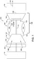
- FIG. 1 is a schematic view of an exemplary rotary machine 100, i.e., a turbomachine, and more specifically a turbine engine.
- rotary machine 100 is a gas turbine engine.
- rotary machine may be any other turbine engine and/or rotary machine, including, without limitation, a steam turbine engine, a gas turbofan aircraft engine, other aircraft engine, a wind turbine, a compressor, and a pump.
- turbine engine 100 includes an intake section 102, a compressor section 104 that is coupled downstream from intake section 102, a combustor section 106 that is coupled downstream from compressor section 104, a turbine section 108 that is coupled downstream from combustor section 106, and an exhaust section 110 that is coupled downstream from turbine section 108.
- Turbine section 108 is coupled to compressor section 104 via a rotor shaft 112. It should be noted that, as used herein, the term "couple” is not limited to a direct mechanical, thermal, electrical, and/or flow communication connection between components, but may also include an indirect mechanical, thermal, electrical, and/or flow communication connection between multiple components.
- combustor section 106 includes a plurality of combustors 114.
- Combustor section 106 is coupled to compressor section 104 such that each combustor 114 is in flow communication with the compressor section 104.
- Rotor shaft 112 is further coupled to a load 116 such as, but not limited to, an electrical generator and/or a mechanical drive application.
- each of compressor section 104 and turbine section 108 includes at least one rotor assembly 118 that is coupled to rotor shaft 112.
- Each rotor assembly 118 of turbine section 108 includes a plurality of circumferentially arranged, radially extending turbine blades 119.
- intake section 102 channels air 120 towards compressor section 104.
- Compressor section 104 compresses inlet air 120 to higher pressures prior to discharging compressed air 122 towards combustor section 106.
- Compressed air 122 is channeled to combustor section 106 where it is mixed with fuel (not shown) and burned to generate high temperature combustion gases 124.
- Combustion gases 124 are channeled downstream towards turbine section 108 and impinge upon turbine blades 119, converting thermal energy to mechanical rotational energy that is used to drive rotor assembly 118 about a longitudinal axis 126.
- combustor section 106 and turbine section 108 are referred to as a hot gas section 109 of turbine engine 100.
- Exhaust gases 128 then discharge through exhaust section 110 to ambient atmosphere.
- components 204 of hot gas section 109 can be exposed to temperatures as high as, for example, 1250 degrees Celsius, creating heat stresses.
- components 204 are also subjected to mechanical stresses during operation, such as stresses from high speed rotation and the push of high-speed hot gases from combustor 106.
- Such extreme operating conditions can cause cracks due to creep and/or fatigue and other defects to form within components 204 of hot gas section 109, requiring repair.
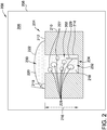
- FIG. 2 is a cross-sectional view of a system 200 for creating a braze joint 202 within one or more of components 204.
- component 204 is described as a component of rotary machine 100 for purposes of illustration, it should be understood that system 200 is also contemplated for creating a braze joint in any suitable component 204 in a wide variety of applications, and is not limited to use with components of rotary machine 100 described herein.
- component 204 is formed from a metal alloy used within the hot gas section 109 or the combustor 106 of turbine engine 100.
- component 204 is fabricated from a cobalt-base or a nickel-base superalloy.
- component 204 may be fabricated from a single crystalline nickel-based superalloy, such as CMSX-4®.
- component 204 is formed from any alloy that can be brazed using the systems and methods described herein.
- System 200 includes an environment 206 for creating braze joint 202.
- environment 206 is a cavity defined within a heating compartment 208.
- heating compartment 208 is a vacuum furnace configured to supply both heat and vacuum to the cavity during the brazing process.
- heating compartment 208 is configured to supply uniform temperatures across environment 206, and to pull sufficient vacuum within environment 206 to remove at least some gases present in environment 206.
- gases include oxygen, nitrogen, carbon dioxide, water vapor, and methane.
- environment 206 is any suitable environment that allows the braze joint to be formed within component 204 as described herein.
- Component 204 includes a base 210 having a base surface 212 and a recess 214 depending inwardly a recess depth 216 from base surface 212 to an inner edge 224.
- recess 214 represents a defect, such as a crack, in base 210 that may occur during normal use of component 204.
- Inner edge 224 represents the innermost or deepest extent of the crack from base surface 212.
- recess 214 may be formed due to the combination of rotational stress, force from rapidly flowing hot gas stream and/or cyclic thermomechanical strain on component 204.
- recess 214 may have been formed by another process, such as, intentionally or unintentionally during a casting or machining process for component 204 or a joint bonding two separately-formed components 204 together.
- Braze joint 202 is formed from a braze material 218.
- braze material 218 includes a pure braze filler alloy, such as DF-4B diffusion braze alloy.
- the braze filler alloy may include one or more of aluminum, silicon, copper, silver, germanium, gold, nickel, cobalt and boron.
- the braze alloy is a multi-component eutectic with relatively low melting point compared to the component 204.
- braze alloys used for components 204 formed from cobalt-base and nickel-base superalloys typically have a melting temperature less than 1120 degrees Celsius, and, more specifically, between 900 and 1100 degrees Celsius.
- braze material 218 includes a blend of a braze powder and a braze filler alloy.
- the braze powder is typically a superalloy for component 204 and has a higher strength and a higher melting point compared to the braze filler alloy. As such, at certain temperatures, the braze alloy is molten while the braze powder is solid, creating a partially molten braze material 218.
- the braze material 218 may consist entirely or substantially of a braze filler alloy, or may comprise other material that allows the brazing joint 202 to form as described herein.
- braze material 218 comprises a braze filler alloy and a braze powder that are mixed with a binder to create a braze paste.
- the braze filler alloy and the braze powder are mixed with eight percent binder.
- the braze paste is semi-solid, which, in some embodiments, allows braze material 218 to be poured or injected into recess 214.
- Such filling techniques are particularly suited for recesses 214 wider than 0.1 millimeter.
- braze paste or pure braze filler alloy may be placed above recess 214 to create a cap 220 and braze material 218 is allowed to flow into recess by capillary effect.
- Such a filling technique is particularly suited for recesses 214 equal to or narrower than 0.1 millimeter.
- environment 206 is heated to a brazing temperature.
- the environment 206 is held at the brazing temperature for 10 minutes to 120 minutes.
- environment 206 is held at the brazing temperature for 20 minutes to 40 minutes, and in some such embodiments, for 30 minutes.
- environment 206 is kept at brazing temperature for any suitable length of time.
- the brazing temperature is lower than the melting temperature of component 204 and high enough to cause braze material 218 to become molten, or partially molten, as described above.
- braze material 218 comprises a braze paste
- the braze alloy melts while the braze powder remains solid, creating a partially-molten braze material 218.
- braze material 218 is placed into recess 214 to fill recess from inner edge 224 to base surface 212.
- additional braze material 218 is placed above base surface 212 to create cap 220.
- Cap 220 is in fluid communication with braze material 218 in recess 214.
- Braze material 218 is then heated to the brazing temperature, burning off most or all of any binder present and causing braze material 218 to become at least partially molten.
- braze paste or pure braze alloy may be placed above recess 214 to create a cap 220 and braze material 218 is allowed to flow into recess 214 by capillary effect.
- the loading of recess 214 may occur at room temperature or may occur by heating environment 206 to a brazing temperature.
- braze material 218 is heated to the brazing temperature, creating an exposed braze surface 222 on at least partially-molten cap 220 and a contact angle 219 between the partially-molten braze material 218 and recess 214.
- pure braze filler wets base surface 212, inner edge 224 and the other surfaces of recess 214 and creates contact angle 219 of less than 90 degrees.
- contact angle 219 is less than or equal to 30 degrees, allowing the braze material to spread over the inner edge 224 and other surfaces of recess 214 and drawing braze material 218 into recess 214 by capillary effect.
- braze material 218 is completely melted at the braze temperature.
- braze material 218 is placed on base surface 212 over recess 214 in its partially-molten state, and is allowed to feed the recess 214 by capillary effect.
- the braze material 218 may fill only a portion of recess 214 such that cap 220 is drawn into recess 214 once the braze material is heated to braze temperature in environment 206.
- braze material 218 after braze material 218 reaches the brazing temperature, becomes at least partially molten, and fully fills the recess, the temperature in environment 206 is lowered and braze material 218 is allowed to cool to solidify braze material 218, creating braze joint 202 within recess 214.
- solidification of braze material 218 causes braze material 218 to shrink, which can lead to solidification defects 228 in braze joint 202.
- Some such solidification defects 228 include a high porosity (both in quantity and size) in the solid braze joint 202, as illustrated by pores 227 in FIG. 2 .
- Other solidification defects 228 include linear indications, or cracks, as illustrated by linear indication 229.
- a first portion 230 of braze material 218 located at or near exposed braze surface 222 decreases in temperature more rapidly than a second portion 232 of braze material 218 located at or near inner edge 224.
- the solidification shrinkage can cause defects 228 to form.
- first portion 230 cooling faster than second portion 232 solidification defects 228 form within solidified braze material 218 near second portion 232.
- component 204 including braze joint 202 is returned to service, at least some such known solidification defects 228 result in reduced tensile strength and a shorter creep life and fatigue life of the braze joint 202.
- the size of cap 220 compared to the size of braze joint 202 can affect an ability of cap 220 to feed shrinkage of braze material 218 within recess 214 during cooling.
- a ratio of modulus of cap 220 to the modulus of braze joint 202 can be used to characterize how effectively cap 220 feeds braze joint 202, where modulus is defined as volume of a geometrical body divided by the heat dissipation area of the geometrical body. For example, if the modulus ratio is less than 1.0, braze material 218 in cap 220 starts and completes solidification earlier than braze material 218 in recess 214 while cooling in environment 206.
- a ratio of the modulus of cap 220 to the modulus of braze joint 202 greater than 1.0 effectively feeds braze material 218 into recess 214 to at least partially compensate for shrinkage during cooling.
- a ratio of the modulus of cap 220 to the modulus of braze joint 202 greater than 1.1 effectively feeds braze material 218 into recess 214 during cooling to at least partially compensate for shrinkage and decrease solidification defects 228.
- a ratio of the modulus of cap 220 to the modulus of braze joint 202 greater than 1.5 particularly effectively feeds braze material 218 into recess 214 during cooling to at least partially compensate for shrinkage and decrease solidification defects 228.
- a ratio of the modulus of cap 220 to the modulus of braze joint 202 greater than 1.5 feeds braze material 218 into recess 214 during cooling to completely compensate for shrinkage and eliminate solidification defects 228 in braze joint 202.
- increasing contact angle 219 at base surface 212 effectively increases the modulus of cap 220, increasing feeding of braze material 218 from cap 220 to recess 214 during cooling to at least partially compensate for shrinkage.
- the size of cap 220 and contact angle 219 are varied to increase feeding capability of cap 220 into recess 214 during cooling.
- FIG. 3 is a cross-sectional view of another exemplary embodiment of a system for creating braze joint 202 within component 204, designated system 300.
- System 300 is similar to system 200, and, accordingly, like components are labeled the same as for system 200.
- System 300 differs from system 200 in that system 300 includes a thermal insulation layer 302 that at least partially covers exposed braze surface 222 of cap 220 of braze material 218.
- thermal insulation layer 302 completely covers cap 220 and a portion of base surface 212.
- braze joint 202 is created by heating braze material 218 to a brazing temperature, causing braze material 218 to become at least partially molten and allowing braze material 218 to enter recess 214.
- thermal insulation layer 302 is placed over exposed braze surface 222 such that thermal insulation layer 302 at least partially covers exposed braze surface 222.
- Thermal insulation layer 302 may include any material that allows the thermal insulation layer 302 to function as described herein.
- the thermal insulation layer 302 is formed from one or more of ceramic material, ceramic fiber, mineral wool, polycrystalline fiber, silica cloth, and any combinations thereof.
- thermal insulation layer 302 causes first portion 230, located near cap 220 and braze surface 222, to cool more slowly than second portion 232, located near inner edge 224. Because of the temperature differential between first portion 230 and second portion 232, solidification of braze material 218 starts and completes earlier near second portion 232 than first portion 230.
- thermal insulation layer 302 causes solidification defects 228 to primarily form in cap 220 near exposed braze surface 222.
- cap 220 is removed or is otherwise not designed to contribute to a strength of braze joint 202. Accordingly, in some embodiments, solidification defects 228 in first portion 230 of braze material 218 do not significantly affect a performance of braze joint 202.
- varying the size of cap 220 compared to the size of braze joint 202 can affect the ability of cap 220 to feed braze material 218 into recess 214 to at least partially compensate for shrinkage during cooling.
- the ratio of modulus of cap 220 to the modulus of braze joint 202 can be used to characterize how effectively cap 220 feeds braze joint 202.
- thermal insulation layer 302 increases the modulus of cap 220, and thus its ratio to the modulus of braze joint 202, when compared to the corresponding ratio for caps 220 without an insulation layer, such as the cap 220 illustrated in system 200.
- thermal insulation layer 302 allows for cap 220 having a smaller width to provide the same amount of feeding of braze joint 202 as cap 220 having a larger width but without an insulation layer.
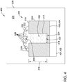
- FIG. 4 is a cross-sectional view of another exemplary embodiment of a system for creating braze joint 202 within component 204, designated system 400.
- System 400 is similar to system 200, and accordingly, like components are labeled the same as system 200.
- System 400 differs from system 200 in that system 400 includes a cooling device 401 operable to extract heat from a location 403 on base 210. More specifically, location 403 is closer to inner edge 224 of recess 214 than to cap 220.
- cooling device 401 includes a thermal conduction element 402 in contact with location 403. Also in the exemplary embodiment, location 403 is a second base surface 404 of base 210 located opposite base surface 212. However, it will be appreciated that location 403 may be any location that is closer to inner edge 224 of recess 214 than to cap 220. In other words, location 403 is selected such that cooling device 401 enhances the heat extraction of second portion 232 of braze material 218 while having less effect on first portion 230 of braze material 218.
- thermal conduction element 402 is configured to extract heat from location 403 of base 210 while environment 206 is cooling. In alternative embodiments, thermal conduction element 402 is configured to extract heat from location 403 of base 210 while environment 206 is actively heating environment 206 and then while environment 206 is cooling. Because thermal conduction element 402 is located closer to second portion 232 than to first portion 230, braze material 218 reduces in temperature faster near second portion 232 than first portion 230.
- Thermal conduction element 402 includes any thermal conductive material and/or system that allows thermal conduction element to function as described herein.
- thermal conduction element 402 includes a heat exchanger.
- Thermal conduction element 402 may be, for example, a plate-fin heat exchanger, a plate heat exchanger, or a tube heat exchanger.
- thermal conductive element 402 includes a graphite plate with embedded cooling channels connected to a cooling media.
- cooling device 401 includes any suitable structure that enables system 400 to function as described herein.
- FIG. 5 is a cross-sectional view of another exemplary system for creating braze joint 202 within component 204, designated system 500.
- System 500 is similar to system 400, and accordingly, like components are labeled the same as system 400.
- System 500 differs from system 400 in that cooling device 401 is implemented as an impingement manifold 502 configured to direct a fluid 504 into impingement with base 210 at location 403.
- location 403 is selected such that fluid 504 impinges a portion of base 210 closer to inner edge 224 of recess 214, and second portion 232, than to cap 220, exposed braze surface 222, and first portion 230.
- location 403 is again second base surface 404 of base 210 located opposite base surface 212.
- location 403 may be any location that is closer to inner edge 224 of recess 214 than to cap 220.
- Impingement manifold 502 is configured to direct fluid 504 to extract heat from location 403 of base 210 while environment 206 is cooling. Because fluid 504 impinges on base 210 at location 403 closer to second portion 232 than to first portion 230, braze material 218 reduces in temperature faster near second portion 232 than first portion 230. Because of the temperature differential between first portion 230 and second portion 232, solidification of braze material 218 occurs more rapidly near second portion 232 than first portion 230.
- solidification defects 228 that form in braze material 218 occur closer to first portion 230 than to second portion 232.
- solidification defects 228 primarily form in cap 220 near exposed braze surface 222.
- cap 220 is removed or is otherwise not designed to contribute to a strength of braze joint 202. Accordingly, solidification defects 228 in first portion 230 of braze material 218 do not significantly affect a performance of braze joint 202.
- Impingement manifold 502 and fluid 504 directed thereby, includes any thermal convective system and/or process that allows the cooling device 401 to function as described herein.
- impingement manifold502 comprises jet nozzles connected to a source of fluid 504 such as a pressurized gas.
- fluid 504 includes one or more of argon, helium, hydrogen, and/or nitrogen.
- insulation layer 302 (shown in FIG. 3 ) and cooling device 401 (shown in FIGs. 4 and 5 ) are illustrated above as being implemented separately, in some embodiments additional advantages in reducing or eliminating solidification defects 228 from braze joint 202 are obtained by implementing insulation layer 302 and cooling device 401 concurrently.
- insulation layer 302 at least partially covers exposed braze surface 222 of cap 220 concurrently with cooling device 401 (e.g., thermal conduction element 402 or impingement manifold 502) operating to extract heat from location 403 of base 210, further facilitating more rapid solidification of braze material 218 near second portion 232 than first portion 230.
- cooling device 401 e.g., thermal conduction element 402 or impingement manifold 502
- FIG. 6 is a flow diagram of an exemplary method 600 of brazing a recess defined within a base, such as brazing recess 214 defined within base 210 (shown in FIGs. 2-5 ).
- the recess depends from a base surface, such as base surface 212, into the base to an inner edge, such as inner edge 224.
- Method 600 includes creating 602 a cap, such as cap 220, of braze material, such as braze material 218, above the recess.
- the cap has an exposed braze surface, such as exposed braze surface 222.
- Method 600 further includes positioning 604 a thermal insulation layer, such as thermal insulation layer 302, over the exposed braze surface.
- Method 600 further includes heating 606 the braze material within an environment, such as environment 206, to create at least partially molten braze material.
- Method 600 further includes cooling 608 the at least partially molten braze material to form a solid braze joint, such as braze joint 202.
- creating 602 a cap of braze material above the recess further includes filling the recess from the surface to the inner edge with the braze paste such that the cap and braze paste in the recess are in fluid communication.
- heating 606 the braze material within an environment to create at least partially molten braze material further includes filling the recess to the inner edge with at least partially molten braze material from the cap via capillary effect.
- cooling 608 the at least partially molten braze material to form the braze joint further comprises passively allowing the environment to cool.
- cooling 608 the at least partially molten braze material includes cooling a location on the base closer to the inner edge than to the cap.
- cooling 608 the at least partially molten braze material further includes solidifying the cap.
- the solid cap has greater porosity than the solid braze joint.
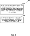
- FIG. 7 is a flow diagram of another exemplary method 700 of brazing a recess defined within a base, such as brazing recess 214 within base 210 (shown in FIGs. 2-5 ).
- the recess depends from a base surface, such as base surface 212, into the base to an inner edge, such as inner edge 224.
- Method 700 includes supplying 702 at least partially molten braze material, such as braze material 218, from a cap, such as cap 220, into the recess to the inner edge.
- Method 700 also includes extracting heat 704 from the base at a location on the base, the location situated closer to the inner edge of the base than to the base surface.
- extracting heat 704 from the base includes conductive cooling at the location using a heat exchanger. In other embodiments, extracting heat 704 from the base includes convective cooling at the location using impingement cooling.
- method 700 further includes positioning at least partially solid braze material above the recess within a environment, such as environment 206.
- supplying 602 the at least partially molten braze material from the cap to the recess further includes heating the environment to a brazing temperature to create the at least partially molten braze material.
- method 700 further includes positioning a thermal insulation layer, such as thermal insulation layer 302, over an exposed braze surface, such as exposed braze surface 222, on the cap before supplying the at least partially molten braze material and extracting heat from the base.
- a thermal insulation layer such as thermal insulation layer 302
- exposed braze surface such as exposed braze surface 222
- the above systems and methods for creating a braze joint within a component facilitates creating braze joints within a component having less or no defects formed within the joint during the braze process, thus decreasing the need to replace the braze joint and increasing the longevity of a component with the braze joint.
- the systems and methods produce a high degree of metallurgical integrity, which imparts superior and reliable mechanical capabilities to the braze joint.
- the systems and methods may be particularly advantageous for components used in extreme heat and high-mechanical stress environments, such as components subjected to the high temperatures and rotational stress in the hot gas section of gas turbines.
- an exemplary technical effect of the systems and methods described herein includes at least one of: (a) reducing defects within a braze joint due to solidification shrinkage; (b) reducing the amount of braze material needed to feed a recess when forming a braze joint in a component; and (c) increase the life of the braze joint.
- Exemplary embodiments of systems and methods for brazing a joint within a component are described above in detail.
- the methods and systems are not limited to the specific embodiments described herein, but rather, components of systems and/or steps of the methods may be utilized independently and separately from other components and/or steps described herein.
- the systems and methods may also be used in combination with many types of components, and are not limited to practice only with the gas turbine engine as described herein. Rather, the exemplary embodiment can be implemented and utilized in connection with many other joint-brazing applications.
Landscapes
- Engineering & Computer Science (AREA)
- Mechanical Engineering (AREA)
- Chemical & Material Sciences (AREA)
- Materials Engineering (AREA)
- Physics & Mathematics (AREA)
- Optics & Photonics (AREA)
- Turbine Rotor Nozzle Sealing (AREA)
- Standing Axle, Rod, Or Tube Structures Coupled By Welding, Adhesion, Or Deposition (AREA)
Abstract
Description
- The field of the disclosure relates generally to braze joints for metal alloys, and more specifically, to thermal control of a braze process.
- For at least some known components fabricated in whole or in part from metal alloys, cracks or defects in the alloy may occur during normal use of the component. For example, at least some known rotary machines use stainless steels and nickel-base, cobalt-base, and iron-base superalloys in components used in the hot flow path of the rotary machine during operation. The hot flow path subjects the components to thermal and/or mechanical stresses and strains. Accordingly, when a crack or defect occurs in the alloys of these components, the repaired crack or defect must be able to similarly withstand the high temperatures, stresses, and strains of the hot flow path.
- One known method of repairing a crack or defect in an alloy is to create a braze joint using a braze process. For some known nickel-based superalloys, such as Rene' N5, Rene' 108, CMSX-4®, and CMSX-6® (registered trademarks of Cannon Muskegon Corporation), use of a braze is the typical technique to salvage a damaged part. In a conventional braze process, a braze material is used to repair a defect in an existing component by filling the gap with the liquid or partially liquid braze material, then allowing the braze material to solidify. At least one known brazing method includes cleaning the defect surfaces to be joined, placing the component with the defect in a vacuum braze furnace, and heating the furnace to a target temperature so that the braze material becomes molten or partially molten, allowing the braze material to flow into the spaces that form the defect. The braze process may be used to fill a gap between two components to join them together or the braze material may be used to form a new component.
- In at least some of the known braze processes for forming braze joints described above, as the braze material begins to cool after the braze material has filled the defect in the component, solidification shrinkage occurs within the joint. Additionally, in at least some known braze joints, as the braze material cools, the braze material closer to the surface of the metal alloy cools faster than the braze material deeper into the defect. This differential cooling, when combined with the solidification shrinkage, can induce solidification defects, such as braze joints with a high degree of porosity and/or hot cracking. In at least some known braze processes, porosities are likely to form when the gap filled with braze material is greater than 0.1 mm and the braze material is a blend of a superalloy powder and a braze filler of a much lower melting point. In at least some known braze processes, hot cracking is likely to occur when the gap filled with braze material is less than 0.1 mm and the braze material is pure braze filler. These defects in the braze joint can reduce tensile strength and shorten creep life and fatigue life of the braze joint, leading to increased wear on the alloy-containing component, which can cause a forced outage of a turbine or additional wear on other internal components. These issues associated with defects in the braze joint can be especially problematic for components designed to be used in high stress areas, such as within the hot flow path of a rotary engine.
- In one aspect, a system for creating a braze joint is provided. The system includes an environment operable to reach a braze temperature sufficient to melt at least a portion of a braze material. The system also includes a component within the environment, the component including a base having a base surface, a recess depending from the base surface into the base to an inner edge, and a braze material within the recess and forming a cap above the base surface. The braze material fills the recess from the cap to the inner edge. The cap has an exposed braze surface. The system also includes an insulation layer that at least partially covers the exposed braze surface.
- In another aspect, a method for brazing a recess defined within a base is provided. The recess depends from a surface of the base into the base to an inner edge. The method includes creating a cap of braze material above the recess. The cap has an exposed braze surface. The method further includes positioning a thermal insulation layer over the exposed braze surface. The method also includes heating the braze material within an environment to create at least partially molten braze material. The method further includes cooling the at least partially molten braze material to form a solid braze joint within the recess.
- In another aspect, a method for brazing a recess defined within a base is provided. The recess depends from a base surface of the base into the base to an inner edge. The method includes supplying at least partially molten braze material from a cap into the recess to the inner edge. The method also includes extracting heat from a location on the base, the location being closer to the inner edge of the recess than to the cap.
- These and other features, aspects, and advantages of the present disclosure will become better understood when the following detailed description is read with reference to the accompanying drawings in which like characters represent like parts throughout the drawings, wherein:
-
FIG. 1 is a schematic view of an exemplary rotary machine; -
FIG. 2 is a cross-sectional view of an exemplary system for creating a braze joint within a component; -
FIG. 3 is a cross-sectional view of another exemplary system for creating a braze joint within a component; -
FIG. 4 is a cross-sectional view of another exemplary system for creating a braze joint within a component; -
FIG. 5 is a cross-sectional view of another exemplary system for creating a braze joint within a component; -
FIG. 6 is a flow diagram of an exemplary method of creating a braze joint; and -
FIG. 7 is a flow diagram of another exemplary method of creating a braze joint. - Unless otherwise indicated, the drawings provided herein are meant to illustrate features of embodiments of the disclosure. These features are believed to be applicable in a wide variety of systems comprising one or more embodiments of the disclosure. As such, the drawings are not meant to include all conventional features known by those of ordinary skill in the art to be required for the practice of the embodiments disclosed herein.
- In the following specification and the claims, reference will be made to a number of terms, which shall be defined to have the following meanings.
- The singular forms "a", "an", and "the" include plural references unless the context clearly dictates otherwise.
- Unless otherwise indicated, approximating language, such as "generally," "substantially," and "about," as used herein indicates that the term so modified may apply to only an approximate degree, as would be recognized by one of ordinary skill in the art, rather than to an absolute or perfect degree. Accordingly, a value modified by a term or terms such as "about," "approximately," and "substantially" is not to be limited to the precise value specified. In at least some instances, the approximating language may correspond to the precision of an instrument for measuring the value. Here and throughout the specification and claims, range limitations may be identified. Such ranges may be combined and/or interchanged, and include all the sub-ranges contained therein unless context or language indicates otherwise. Additionally, unless otherwise indicated, the terms "first," "second," etc. are used herein merely as labels, and are not intended to impose ordinal, positional, or hierarchical requirements on the items to which these terms refer. Moreover, reference to, for example, a "second" item does not require or preclude the existence of, for example, a "first" or lower-numbered item or a "third" or higher-numbered item.
- The systems and methods described herein relate to creating a braze joint within a component. Specifically, in an exemplary embodiment, the system includes an environment operable to reach a braze temperature sufficient to melt at least a portion of a braze material. The system also includes a component within the environment, the component including a base having a base surface, a recess depending from the base surface into the base to an inner edge, and a braze material within the recess and forming a cap above the base surface. The braze material fills the recess from the cap to the inner edge. The cap has an exposed braze surface. In some embodiments, the system also includes an insulation layer that at least partially covers the exposed braze surface of the cap. After the environment is heated to the brazing temperature, the system facilitates less rapid heat dissipation from the exposed braze surface of the cap, as compared to a system without the insulation layer. Additionally or alternatively, the system includes a cooling system operable to extract heat from the base at a location closer to the inner edge of the recess than to the cap, which facilitates more rapid cooling of the braze joint compared to the exposed braze surface of the cap. Accordingly, the system facilitates creating the braze joint having fewer or no solidification defects within the recess, relative to the cap extending above the base surface, during the braze process.
-
FIG. 1 is a schematic view of an exemplaryrotary machine 100, i.e., a turbomachine, and more specifically a turbine engine. In the exemplary embodiment,rotary machine 100 is a gas turbine engine. Alternatively, rotary machine may be any other turbine engine and/or rotary machine, including, without limitation, a steam turbine engine, a gas turbofan aircraft engine, other aircraft engine, a wind turbine, a compressor, and a pump. In the exemplary embodiment,turbine engine 100 includes anintake section 102, acompressor section 104 that is coupled downstream fromintake section 102, acombustor section 106 that is coupled downstream fromcompressor section 104, aturbine section 108 that is coupled downstream fromcombustor section 106, and anexhaust section 110 that is coupled downstream fromturbine section 108.Turbine section 108 is coupled tocompressor section 104 via arotor shaft 112. It should be noted that, as used herein, the term "couple" is not limited to a direct mechanical, thermal, electrical, and/or flow communication connection between components, but may also include an indirect mechanical, thermal, electrical, and/or flow communication connection between multiple components. In the exemplary embodiment,combustor section 106 includes a plurality ofcombustors 114.Combustor section 106 is coupled tocompressor section 104 such that each combustor 114 is in flow communication with thecompressor section 104.Rotor shaft 112 is further coupled to aload 116 such as, but not limited to, an electrical generator and/or a mechanical drive application. In the exemplary embodiment, each ofcompressor section 104 andturbine section 108 includes at least onerotor assembly 118 that is coupled torotor shaft 112. Eachrotor assembly 118 ofturbine section 108 includes a plurality of circumferentially arranged, radially extending turbine blades 119. - In operation,
intake section 102channels air 120 towardscompressor section 104.Compressor section 104 compressesinlet air 120 to higher pressures prior to dischargingcompressed air 122 towardscombustor section 106.Compressed air 122 is channeled tocombustor section 106 where it is mixed with fuel (not shown) and burned to generate hightemperature combustion gases 124.Combustion gases 124 are channeled downstream towardsturbine section 108 and impinge upon turbine blades 119, converting thermal energy to mechanical rotational energy that is used to driverotor assembly 118 about alongitudinal axis 126. Often,combustor section 106 andturbine section 108 are referred to as ahot gas section 109 ofturbine engine 100.Exhaust gases 128 then discharge throughexhaust section 110 to ambient atmosphere. - In some embodiments, during operation of
turbine engine 100,components 204 ofhot gas section 109, such as but not limited to turbine blades 119, which may include stator vanes (not shown) and shrouds (not shown), can be exposed to temperatures as high as, for example, 1250 degrees Celsius, creating heat stresses. Inturbine section 108,components 204 are also subjected to mechanical stresses during operation, such as stresses from high speed rotation and the push of high-speed hot gases fromcombustor 106. Such extreme operating conditions can cause cracks due to creep and/or fatigue and other defects to form withincomponents 204 ofhot gas section 109, requiring repair. -
FIG. 2 is a cross-sectional view of asystem 200 for creating a braze joint 202 within one or more ofcomponents 204. Althoughcomponent 204 is described as a component ofrotary machine 100 for purposes of illustration, it should be understood thatsystem 200 is also contemplated for creating a braze joint in anysuitable component 204 in a wide variety of applications, and is not limited to use with components ofrotary machine 100 described herein. - In some embodiments,
component 204 is formed from a metal alloy used within thehot gas section 109 or thecombustor 106 ofturbine engine 100. In some such embodiments,component 204 is fabricated from a cobalt-base or a nickel-base superalloy. For example,component 204 may be fabricated from a single crystalline nickel-based superalloy, such as CMSX-4®. In alternative embodiments,component 204 is formed from any alloy that can be brazed using the systems and methods described herein. -
System 200 includes anenvironment 206 for creating braze joint 202. In some embodiments,environment 206 is a cavity defined within aheating compartment 208. In the exemplary embodiment,heating compartment 208 is a vacuum furnace configured to supply both heat and vacuum to the cavity during the brazing process. For example,heating compartment 208 is configured to supply uniform temperatures acrossenvironment 206, and to pull sufficient vacuum withinenvironment 206 to remove at least some gases present inenvironment 206. In an embodiment, such gases include oxygen, nitrogen, carbon dioxide, water vapor, and methane. In alternative embodiments,environment 206 is any suitable environment that allows the braze joint to be formed withincomponent 204 as described herein. -
Component 204 includes a base 210 having abase surface 212 and arecess 214 depending inwardly arecess depth 216 frombase surface 212 to aninner edge 224. In the exemplary embodiment,recess 214 represents a defect, such as a crack, inbase 210 that may occur during normal use ofcomponent 204.Inner edge 224 represents the innermost or deepest extent of the crack frombase surface 212. For example, in embodiments wherecomponent 204 is formed from a metal alloy used within thehot gas section 109 ofturbine engine 100,recess 214 may be formed due to the combination of rotational stress, force from rapidly flowing hot gas stream and/or cyclic thermomechanical strain oncomponent 204. In alternative embodiments,recess 214 may have been formed by another process, such as, intentionally or unintentionally during a casting or machining process forcomponent 204 or a joint bonding two separately-formedcomponents 204 together. - Braze joint 202 is formed from a
braze material 218. In one embodiment,braze material 218 includes a pure braze filler alloy, such as DF-4B diffusion braze alloy. The braze filler alloy may include one or more of aluminum, silicon, copper, silver, germanium, gold, nickel, cobalt and boron. In the exemplary embodiment, the braze alloy is a multi-component eutectic with relatively low melting point compared to thecomponent 204. For example, braze alloys used forcomponents 204 formed from cobalt-base and nickel-base superalloys typically have a melting temperature less than 1120 degrees Celsius, and, more specifically, between 900 and 1100 degrees Celsius. In another embodiment,braze material 218 includes a blend of a braze powder and a braze filler alloy. The braze powder is typically a superalloy forcomponent 204 and has a higher strength and a higher melting point compared to the braze filler alloy. As such, at certain temperatures, the braze alloy is molten while the braze powder is solid, creating a partiallymolten braze material 218. In alternative embodiments, thebraze material 218 may consist entirely or substantially of a braze filler alloy, or may comprise other material that allows the brazing joint 202 to form as described herein. - In an embodiment,
braze material 218 comprises a braze filler alloy and a braze powder that are mixed with a binder to create a braze paste. For example, but not by way of limitation, the braze filler alloy and the braze powder are mixed with eight percent binder. The braze paste is semi-solid, which, in some embodiments, allowsbraze material 218 to be poured or injected intorecess 214. Such filling techniques are particularly suited forrecesses 214 wider than 0.1 millimeter. In alternative embodiments, braze paste or pure braze filler alloy may be placed aboverecess 214 to create acap 220 andbraze material 218 is allowed to flow into recess by capillary effect. Such a filling technique is particularly suited forrecesses 214 equal to or narrower than 0.1 millimeter. - In some embodiments, during the brazing process,
environment 206 is heated to a brazing temperature. In some embodiments, theenvironment 206 is held at the brazing temperature for 10 minutes to 120 minutes. In some such embodiments,environment 206 is held at the brazing temperature for 20 minutes to 40 minutes, and in some such embodiments, for 30 minutes. Alternatively,environment 206 is kept at brazing temperature for any suitable length of time. The brazing temperature is lower than the melting temperature ofcomponent 204 and high enough to causebraze material 218 to become molten, or partially molten, as described above. In the exemplary embodiment, in which brazematerial 218 comprises a braze paste, at the brazing temperature, the braze alloy melts while the braze powder remains solid, creating a partially-molten braze material 218. In some such embodiments, beforeenvironment 206 is heated to the brazing temperature, solid orpaste braze material 218 is placed intorecess 214 to fill recess frominner edge 224 tobase surface 212. In some such embodiments,additional braze material 218 is placed abovebase surface 212 to createcap 220.Cap 220 is in fluid communication withbraze material 218 inrecess 214.Braze material 218 is then heated to the brazing temperature, burning off most or all of any binder present and causingbraze material 218 to become at least partially molten. - As described above, in alternative embodiments, braze paste or pure braze alloy may be placed above
recess 214 to create acap 220 andbraze material 218 is allowed to flow intorecess 214 by capillary effect. The loading ofrecess 214 may occur at room temperature or may occur byheating environment 206 to a brazing temperature. In an exemplary embodiment,braze material 218 is heated to the brazing temperature, creating an exposedbraze surface 222 on at least partially-molten cap 220 and acontact angle 219 between the partially-molten braze material 218 andrecess 214. In some such embodiments, pure braze filler wetsbase surface 212,inner edge 224 and the other surfaces ofrecess 214 and createscontact angle 219 of less than 90 degrees. In further embodiments,contact angle 219 is less than or equal to 30 degrees, allowing the braze material to spread over theinner edge 224 and other surfaces ofrecess 214 and drawingbraze material 218 intorecess 214 by capillary effect. In alternative embodiments,braze material 218 is completely melted at the braze temperature. In alternative or additional embodiments,braze material 218 is placed onbase surface 212 overrecess 214 in its partially-molten state, and is allowed to feed therecess 214 by capillary effect. In further embodiments, thebraze material 218 may fill only a portion ofrecess 214 such thatcap 220 is drawn intorecess 214 once the braze material is heated to braze temperature inenvironment 206. - In some embodiments, after
braze material 218 reaches the brazing temperature, becomes at least partially molten, and fully fills the recess, the temperature inenvironment 206 is lowered andbraze material 218 is allowed to cool to solidifybraze material 218, creating braze joint 202 withinrecess 214. In some embodiments, solidification ofbraze material 218 causes brazematerial 218 to shrink, which can lead tosolidification defects 228 in braze joint 202. Somesuch solidification defects 228 include a high porosity (both in quantity and size) in the solid braze joint 202, as illustrated bypores 227 inFIG. 2 .Other solidification defects 228 include linear indications, or cracks, as illustrated bylinear indication 229. In some embodiments, asbase 210 andbraze material 218 begin cool, afirst portion 230 ofbraze material 218 located at or near exposedbraze surface 222 decreases in temperature more rapidly than asecond portion 232 ofbraze material 218 located at or nearinner edge 224. When one portion ofbraze material 218 cools faster than another portion, such asfirst portion 230 cooling faster inenvironment 206 thansecond portion 232, the solidification shrinkage can causedefects 228 to form. In this exemplary embodiment, byfirst portion 230 cooling faster thansecond portion 232,solidification defects 228 form within solidifiedbraze material 218 nearsecond portion 232. Whencomponent 204 including braze joint 202 is returned to service, at least some such knownsolidification defects 228 result in reduced tensile strength and a shorter creep life and fatigue life of the braze joint 202. - In some embodiments, the size of
cap 220 compared to the size of braze joint 202 can affect an ability ofcap 220 to feed shrinkage ofbraze material 218 withinrecess 214 during cooling. In some such embodiments, a ratio of modulus ofcap 220 to the modulus of braze joint 202 can be used to characterize how effectively cap 220 feeds braze joint 202, where modulus is defined as volume of a geometrical body divided by the heat dissipation area of the geometrical body. For example, if the modulus ratio is less than 1.0,braze material 218 incap 220 starts and completes solidification earlier thanbraze material 218 inrecess 214 while cooling inenvironment 206. In one embodiment, a ratio of the modulus ofcap 220 to the modulus of braze joint 202 greater than 1.0 effectively feedsbraze material 218 intorecess 214 to at least partially compensate for shrinkage during cooling. In some embodiments, a ratio of the modulus ofcap 220 to the modulus of braze joint 202 greater than 1.1 effectively feedsbraze material 218 intorecess 214 during cooling to at least partially compensate for shrinkage and decreasesolidification defects 228. In further embodiments, a ratio of the modulus ofcap 220 to the modulus of braze joint 202 greater than 1.5 particularly effectively feedsbraze material 218 intorecess 214 during cooling to at least partially compensate for shrinkage and decreasesolidification defects 228. In alternative embodiments, a ratio of the modulus ofcap 220 to the modulus of braze joint 202 greater than 1.5 feeds brazematerial 218 intorecess 214 during cooling to completely compensate for shrinkage and eliminatesolidification defects 228 in braze joint 202. Additionally or alternatively, increasingcontact angle 219 atbase surface 212 effectively increases the modulus ofcap 220, increasing feeding ofbraze material 218 fromcap 220 to recess 214 during cooling to at least partially compensate for shrinkage. In various embodiments, the size ofcap 220 andcontact angle 219 are varied to increase feeding capability ofcap 220 intorecess 214 during cooling. -
FIG. 3 is a cross-sectional view of another exemplary embodiment of a system for creating braze joint 202 withincomponent 204, designatedsystem 300.System 300 is similar tosystem 200, and, accordingly, like components are labeled the same as forsystem 200.System 300 differs fromsystem 200 in thatsystem 300 includes athermal insulation layer 302 that at least partially covers exposedbraze surface 222 ofcap 220 ofbraze material 218. In the exemplary embodiment,thermal insulation layer 302 completely coverscap 220 and a portion ofbase surface 212. Likesystem 200, insystem 300 braze joint 202 is created byheating braze material 218 to a brazing temperature, causingbraze material 218 to become at least partially molten and allowingbraze material 218 to enterrecess 214. In some embodiments ofsystem 300, beforeheating braze material 218 to the brazing temperature, or afterbraze material 218 is made at least partially molten,thermal insulation layer 302 is placed over exposedbraze surface 222 such thatthermal insulation layer 302 at least partially covers exposedbraze surface 222. -
Thermal insulation layer 302 may include any material that allows thethermal insulation layer 302 to function as described herein. In some embodiments, thethermal insulation layer 302 is formed from one or more of ceramic material, ceramic fiber, mineral wool, polycrystalline fiber, silica cloth, and any combinations thereof. - Similar to
system 200, in the exemplary embodiment ofsystem 300, oncecomponent 204 has been heated inenvironment 206 for sufficient time to create at least partiallymolten braze material 218,environment 206 is allowed to cool from the brazing temperature. Asenvironment 206 cools,base 210 andbraze material 218 also begin to cool, allowingbraze material 218 to solidify forming braze joint 202. Unlikesystem 200, in some embodiments,thermal insulation layer 302 causesfirst portion 230, located nearcap 220 and brazesurface 222, to cool more slowly thansecond portion 232, located nearinner edge 224. Because of the temperature differential betweenfirst portion 230 andsecond portion 232, solidification ofbraze material 218 starts and completes earlier nearsecond portion 232 thanfirst portion 230. Accordingly, as shrinkage occurs inbraze material 218 during solidification, anysolidification defects 228 that form inbraze material 218 occur closer tofirst portion 230 than tosecond portion 232. More specifically, in the exemplary embodiment,thermal insulation layer 302 causessolidification defects 228 to primarily form incap 220 near exposedbraze surface 222. Beforecomponent 204 is returned to service,cap 220 is removed or is otherwise not designed to contribute to a strength of braze joint 202. Accordingly, in some embodiments,solidification defects 228 infirst portion 230 ofbraze material 218 do not significantly affect a performance of braze joint 202. - Like with
system 200, insystem 300, varying the size ofcap 220 compared to the size of braze joint 202, in combination with applyingthermal insulation layer 302, can affect the ability ofcap 220 to feedbraze material 218 intorecess 214 to at least partially compensate for shrinkage during cooling. In some such embodiments, the ratio of modulus ofcap 220 to the modulus of braze joint 202 can be used to characterize how effectively cap 220 feeds braze joint 202. In some further embodiments,thermal insulation layer 302 increases the modulus ofcap 220, and thus its ratio to the modulus of braze joint 202, when compared to the corresponding ratio forcaps 220 without an insulation layer, such as thecap 220 illustrated insystem 200. In some such embodiments,thermal insulation layer 302 allows forcap 220 having a smaller width to provide the same amount of feeding of braze joint 202 ascap 220 having a larger width but without an insulation layer. -
FIG. 4 is a cross-sectional view of another exemplary embodiment of a system for creating braze joint 202 withincomponent 204, designatedsystem 400.System 400 is similar tosystem 200, and accordingly, like components are labeled the same assystem 200.System 400 differs fromsystem 200 in thatsystem 400 includes a cooling device 401 operable to extract heat from a location 403 onbase 210. More specifically, location 403 is closer toinner edge 224 ofrecess 214 than to cap 220. - In the exemplary embodiment, cooling device 401 includes a thermal conduction element 402 in contact with location 403. Also in the exemplary embodiment, location 403 is a second base surface 404 of
base 210 locatedopposite base surface 212. However, it will be appreciated that location 403 may be any location that is closer toinner edge 224 ofrecess 214 than to cap 220. In other words, location 403 is selected such that cooling device 401 enhances the heat extraction ofsecond portion 232 ofbraze material 218 while having less effect onfirst portion 230 ofbraze material 218. - Similar to
system 200, in the exemplary embodiment ofsystem 400, aftercomponent 204 has been heated inenvironment 206 for sufficient time to create at least partiallymolten braze material 218,environment 206 is allowed to cool from the brazing temperature. In the exemplary embodiment, thermal conduction element 402 is configured to extract heat from location 403 ofbase 210 whileenvironment 206 is cooling. In alternative embodiments, thermal conduction element 402 is configured to extract heat from location 403 ofbase 210 whileenvironment 206 is actively heatingenvironment 206 and then whileenvironment 206 is cooling. Because thermal conduction element 402 is located closer tosecond portion 232 than tofirst portion 230,braze material 218 reduces in temperature faster nearsecond portion 232 thanfirst portion 230. Because of the temperature differential betweenfirst portion 230 andsecond portion 232, solidification ofbraze material 218 occurs more rapidly nearsecond portion 232 thanfirst portion 230. Accordingly, as shrinkage occurs inbraze material 218 during solidification,solidification defects 228 that form inbraze material 218 occur closer tofirst portion 230 than tosecond portion 232. In the exemplary embodiment,solidification defects 228 primarily form incap 220 near exposedbraze surface 222. Beforecomponent 204 is returned to service,cap 220 is removed or is otherwise not designed to contribute to a strength of braze joint 202. Accordingly,solidification defects 228 infirst portion 230 ofbraze material 218 do not significantly affect a performance of braze joint 202. - Thermal conduction element 402 includes any thermal conductive material and/or system that allows thermal conduction element to function as described herein. In some embodiments, thermal conduction element 402 includes a heat exchanger. Thermal conduction element 402 may be, for example, a plate-fin heat exchanger, a plate heat exchanger, or a tube heat exchanger. In still further embodiments, thermal conductive element 402 includes a graphite plate with embedded cooling channels connected to a cooling media. In alternative embodiments, cooling device 401 includes any suitable structure that enables
system 400 to function as described herein. -
FIG. 5 is a cross-sectional view of another exemplary system for creating braze joint 202 withincomponent 204, designatedsystem 500.System 500 is similar tosystem 400, and accordingly, like components are labeled the same assystem 400.System 500 differs fromsystem 400 in that cooling device 401 is implemented as an impingement manifold 502 configured to direct a fluid 504 into impingement withbase 210 at location 403. As above, location 403 is selected such thatfluid 504 impinges a portion ofbase 210 closer toinner edge 224 ofrecess 214, andsecond portion 232, than to cap 220, exposedbraze surface 222, andfirst portion 230. In the illustrated embodiment, location 403 is again second base surface 404 ofbase 210 locatedopposite base surface 212. Alternatively, location 403 may be any location that is closer toinner edge 224 ofrecess 214 than to cap 220. - Similar to
system 200, in the exemplary embodiment ofsystem 500, aftercomponent 204 has been heated inenvironment 206 for sufficient time to create at least partiallymolten braze material 218,environment 206 is allowed to cool from the brazing temperature. Impingement manifold 502 is configured to direct fluid 504 to extract heat from location 403 ofbase 210 whileenvironment 206 is cooling. Becausefluid 504 impinges onbase 210 at location 403 closer tosecond portion 232 than tofirst portion 230,braze material 218 reduces in temperature faster nearsecond portion 232 thanfirst portion 230. Because of the temperature differential betweenfirst portion 230 andsecond portion 232, solidification ofbraze material 218 occurs more rapidly nearsecond portion 232 thanfirst portion 230. Accordingly, as shrinkage occurs inbraze material 218 during solidification,solidification defects 228 that form inbraze material 218 occur closer tofirst portion 230 than tosecond portion 232. In the exemplary embodiment,solidification defects 228 primarily form incap 220 near exposedbraze surface 222. Beforecomponent 204 is returned to service,cap 220 is removed or is otherwise not designed to contribute to a strength of braze joint 202. Accordingly,solidification defects 228 infirst portion 230 ofbraze material 218 do not significantly affect a performance of braze joint 202. - Impingement manifold 502, and
fluid 504 directed thereby, includes any thermal convective system and/or process that allows the cooling device 401 to function as described herein. In some embodiments, impingement manifold502 comprises jet nozzles connected to a source offluid 504 such as a pressurized gas. In some such embodiments,fluid 504 includes one or more of argon, helium, hydrogen, and/or nitrogen. - Although insulation layer 302 (shown in
FIG. 3 ) and cooling device 401 (shown inFIGs. 4 and5 ) are illustrated above as being implemented separately, in some embodiments additional advantages in reducing or eliminatingsolidification defects 228 from braze joint 202 are obtained by implementinginsulation layer 302 and cooling device 401 concurrently. In other words, during the cool-down phase afterenvironment 206 is heated to the brazing temperature,insulation layer 302 at least partially covers exposedbraze surface 222 ofcap 220 concurrently with cooling device 401 (e.g., thermal conduction element 402 or impingement manifold 502) operating to extract heat from location 403 ofbase 210, further facilitating more rapid solidification ofbraze material 218 nearsecond portion 232 thanfirst portion 230. -
FIG. 6 is a flow diagram of anexemplary method 600 of brazing a recess defined within a base, such asbrazing recess 214 defined within base 210 (shown inFIGs. 2-5 ). The recess depends from a base surface, such asbase surface 212, into the base to an inner edge, such asinner edge 224.Method 600 includes creating 602 a cap, such ascap 220, of braze material, such asbraze material 218, above the recess. The cap has an exposed braze surface, such as exposedbraze surface 222.Method 600 further includes positioning 604 a thermal insulation layer, such asthermal insulation layer 302, over the exposed braze surface.Method 600 further includesheating 606 the braze material within an environment, such asenvironment 206, to create at least partially molten braze material.Method 600 further includes cooling 608 the at least partially molten braze material to form a solid braze joint, such as braze joint 202. - In some embodiments in which the braze material is a braze paste comprising a braze filler alloy, a braze powder, and a binder, creating 602 a cap of braze material above the recess further includes filling the recess from the surface to the inner edge with the braze paste such that the cap and braze paste in the recess are in fluid communication. In further embodiments,
heating 606 the braze material within an environment to create at least partially molten braze material further includes filling the recess to the inner edge with at least partially molten braze material from the cap via capillary effect. In certain embodiments, cooling 608 the at least partially molten braze material to form the braze joint further comprises passively allowing the environment to cool. - In some embodiments, cooling 608 the at least partially molten braze material includes cooling a location on the base closer to the inner edge than to the cap. In particular embodiments, cooling 608 the at least partially molten braze material further includes solidifying the cap. In some such embodiments, the solid cap has greater porosity than the solid braze joint.
-
FIG. 7 is a flow diagram of anotherexemplary method 700 of brazing a recess defined within a base, such asbrazing recess 214 within base 210 (shown inFIGs. 2-5 ). The recess depends from a base surface, such asbase surface 212, into the base to an inner edge, such asinner edge 224.Method 700 includes supplying 702 at least partially molten braze material, such asbraze material 218, from a cap, such ascap 220, into the recess to the inner edge.Method 700 also includes extractingheat 704 from the base at a location on the base, the location situated closer to the inner edge of the base than to the base surface. - In some embodiments, extracting
heat 704 from the base includes conductive cooling at the location using a heat exchanger. In other embodiments, extractingheat 704 from the base includes convective cooling at the location using impingement cooling. - In some embodiments,
method 700 further includes positioning at least partially solid braze material above the recess within a environment, such asenvironment 206. In some such embodiments, supplying 602 the at least partially molten braze material from the cap to the recess further includes heating the environment to a brazing temperature to create the at least partially molten braze material. - In particular embodiments,
method 700 further includes positioning a thermal insulation layer, such asthermal insulation layer 302, over an exposed braze surface, such as exposedbraze surface 222, on the cap before supplying the at least partially molten braze material and extracting heat from the base. - The above systems and methods for creating a braze joint within a component facilitates creating braze joints within a component having less or no defects formed within the joint during the braze process, thus decreasing the need to replace the braze joint and increasing the longevity of a component with the braze joint. The systems and methods produce a high degree of metallurgical integrity, which imparts superior and reliable mechanical capabilities to the braze joint. The systems and methods may be particularly advantageous for components used in extreme heat and high-mechanical stress environments, such as components subjected to the high temperatures and rotational stress in the hot gas section of gas turbines.
- Additionally, an exemplary technical effect of the systems and methods described herein includes at least one of: (a) reducing defects within a braze joint due to solidification shrinkage; (b) reducing the amount of braze material needed to feed a recess when forming a braze joint in a component; and (c) increase the life of the braze joint.
- Exemplary embodiments of systems and methods for brazing a joint within a component are described above in detail. The methods and systems are not limited to the specific embodiments described herein, but rather, components of systems and/or steps of the methods may be utilized independently and separately from other components and/or steps described herein. For example, the systems and methods may also be used in combination with many types of components, and are not limited to practice only with the gas turbine engine as described herein. Rather, the exemplary embodiment can be implemented and utilized in connection with many other joint-brazing applications.
- Although specific features of various embodiments of the present disclosure may be shown in some drawings and not in others, this is for convenience only. In accordance with the principles of embodiments of the present disclosure, any feature of a drawing may be referenced and/or claimed in combination with any feature of any other drawing.
- This written description uses examples to disclose the embodiments of the present disclosure, including the best mode, and also to enable any person skilled in the art to practice embodiments of the present disclosure, including making and using any devices or systems and performing any incorporated methods. The patentable scope of the embodiments described herein is defined by the claims, and may include other examples that occur to those skilled in the art. Such other examples are intended to be within the scope of the claims if they have structural elements that do not differ from the literal language of the claims, or if they include equivalent structural elements with insubstantial differences from the literal languages of the claims.
Claims (15)
- A system (200, 300, 400, 500) for creating a braze joint (202), the system (200, 300, 400, 500) comprising:an environment (206) operable to reach a braze temperature sufficient to melt at least a portion of a braze material (218);a component (204) within said environment (206), said component (204) comprising:a base (210) comprising a base surface (212);a recess (214) depending from said base surface (212) into said base (210) to an inner edge (224); andsaid braze material (218) within said recess (214) and forming a cap (220) above said base surface (212), said braze material (218) filling said recess (214) from said cap (220) to said inner edge (224), said cap (220) having an exposed braze surface (222); andan insulation layer (302) at least partially covering said exposed braze surface (222).
- The system (200, 300, 400, 500) in accordance with Claim 1, wherein said braze material (218) comprises a braze filler alloy.
- The system (200, 300, 400, 500) in accordance with Claim 2, wherein said braze material (218) comprises a braze paste including said braze alloy and a braze powder, said braze powder having a higher melting point than said braze filler alloy.
- The system (200, 300, 400, 500) in accordance with Claim 1, wherein said insulation layer (302) comprises at least one of ceramic, ceramic fiber, mineral wool, polycrystalline fiber, and silica cloth, and wherein said insulation layer (302) completely covers said cap (220) and at least partially covers said base surface (212).
- The system (200, 300, 400, 500) in accordance with Claim 1, further comprising a cooling device (401) operable to extract heat from a location (403) on said base (210), said location (403) being closer to said inner edge (224) of said recess (214) than to said cap (220).
- The system (200, 300, 400, 500) in accordance with Claim 1, wherein said insulation layer (302) causes a ratio of modulus of said cap (220) to modulus of said braze joint (202) to be greater than or equal to 1.1, where modulus is defined as a volume of a geometrical body divided by a heat dissipation area of the geometrical body.
- A method (600) of brazing a recess (214) defined within a base (210), the recess (214) depending from a base surface (212) of the base (210) into the base (210) to an inner edge (224), the method comprising:creating (602) a cap (220) of braze material (218) above the recess (214), the cap (220) having an exposed braze surface (222);positioning (604) a thermal insulation layer (302) over the exposed braze surface (222);heating (606) the braze material (218) within an environment (206) to create at least partially molten braze material (218); andcooling (608) the at least partially molten braze material (218) to form a solid braze joint (202) within the recess (214).
- The method in accordance with Claim 7, wherein the braze material (218) is a braze paste comprising a braze filler alloy, a braze powder, and a binder, and wherein creating (602) a cap (220) of braze material (218) above the recess (214) further comprises filling the recess (214) from the surface to the inner edge (224) with the braze paste such that the cap (220) and braze paste in the recess (214) are in fluid communication.
- The method in accordance with Claim 7, wherein heating (606) the braze material (218) within an environment (206) to create at least partially molten braze material (218) further comprises filling the recess (214) to the inner edge (224) with at least partially molten braze material (218) from the cap (220) via capillary effect.
- The method in accordance with Claim 7, wherein cooling (608) the at least partially molten braze material (218) comprises cooling a location (403) on the base (210) closer to the inner edge (224) than to the cap (220).
- The method in accordance with Claim 7, wherein cooling (608) the at least partially molten braze material (218) further comprises solidifying the cap (220), wherein the solid cap (220) has greater porosity than the solid braze joint (202).
- A method (700) of brazing a recess (214) defined within a base (210), the recess (214) depending from a base surface (212) of the base (210) into the base (210) to an inner edge (224), the method comprising:supplying (702) at least partially molten braze material (218) from a cap (220) into the recess (214) to the inner edge (224); andextracting (704) heat from a location (403) on the base (210), the location (403) being closer to the inner edge (224) of the recess (214) than to the cap (220).
- The method in accordance with Claim 12, wherein extracting heat (704) further comprises conductively cooling at the location (403) using a heat exchanger (402).
- The method in accordance with Claim 12, wherein extracting heat (704) further comprises impingement cooling at the location (403).
- The method in accordance with Claim 12, further comprising positioning at least partially solid braze material (218) above the recess (214) within an environment (206), wherein supplying the at least partially molten braze material (218) from the cap (220) to the recess (214) further comprises heating the environment (206) to a brazing temperature to create the at least partially molten braze material (218).
Applications Claiming Priority (1)
| Application Number | Priority Date | Filing Date | Title |
|---|---|---|---|
| US16/685,548 US11633797B2 (en) | 2019-11-15 | 2019-11-15 | Braze joints for a component and methods of forming the same |
Publications (3)
| Publication Number | Publication Date |
|---|---|
| EP3822013A2 true EP3822013A2 (en) | 2021-05-19 |
| EP3822013A3 EP3822013A3 (en) | 2021-06-02 |
| EP3822013B1 EP3822013B1 (en) | 2022-08-17 |
Family
ID=73288375
Family Applications (1)
| Application Number | Title | Priority Date | Filing Date |
|---|---|---|---|
| EP20206552.0A Active EP3822013B1 (en) | 2019-11-15 | 2020-11-09 | System for creating a braze joint, and methods of brazing a recess defined within a base |
Country Status (4)
| Country | Link |
|---|---|
| US (2) | US11633797B2 (en) |
| EP (1) | EP3822013B1 (en) |
| JP (1) | JP7703311B2 (en) |
| CN (1) | CN112809121B (en) |
Families Citing this family (1)
| Publication number | Priority date | Publication date | Assignee | Title |
|---|---|---|---|---|
| CN119658045A (en) * | 2023-09-12 | 2025-03-21 | 通用电气技术有限公司 | Braze repair method for reducing eutectic phases |
Family Cites Families (66)
| Publication number | Priority date | Publication date | Assignee | Title |
|---|---|---|---|---|
| US2714760A (en) * | 1951-07-02 | 1955-08-09 | Curtiss Wright Corp | Method of brazing and joint produced thereby |
| US2908072A (en) * | 1956-06-25 | 1959-10-13 | Glidden Co | Brazing paste and process of brazing |
| US3061912A (en) * | 1957-04-04 | 1962-11-06 | Curtiss Wright Corp | Fabrication of porous sheet material by brazing |
| US3130293A (en) * | 1959-07-31 | 1964-04-21 | Bukata Stephen | Brazing furnace |
| US3476862A (en) * | 1968-05-16 | 1969-11-04 | Abar Corp | Electric resistance heating elements |
| GB1328041A (en) * | 1971-03-01 | 1973-08-22 | Ipsen Ind Int Gmbh | Vacuum furnaces |
| GB1450912A (en) * | 1973-07-31 | 1976-09-29 | Welding Inst | Arc welding process |
| US3860222A (en) * | 1973-11-02 | 1975-01-14 | Wall Colmonoy Corp | Cooling system for vacuum furnaces |
| US4886449A (en) * | 1982-12-04 | 1989-12-12 | General Motors Corporation | Vacuum brazing of aluminum alloy workpieces |
| US4701127A (en) * | 1982-12-10 | 1987-10-20 | Borg-Warner Corporation | Controlled atmosphere capsule for fluxless brazing |
| US4906182A (en) * | 1988-08-25 | 1990-03-06 | Abar Ipsen Industries, Inc. | Gas cooling system for processing furnace |
| JPH0248132Y2 (en) * | 1988-09-16 | 1990-12-18 | ||
| US5016707A (en) * | 1989-12-28 | 1991-05-21 | Sundstrand Corporation | Multi-pass crossflow jet impingement heat exchanger |
| US5020331A (en) * | 1990-02-09 | 1991-06-04 | National Refrigeration Products, Inc. | Refrigerant reclamation system |
| JPH0739483Y2 (en) * | 1990-11-15 | 1995-09-13 | 千住金属工業株式会社 | Reflow furnace |
| US5267257A (en) * | 1991-08-14 | 1993-11-30 | Grier-Jhawar-Mercer, Inc. | Vacuum furnace with convection heating and cooling |
| US5172847A (en) * | 1991-09-25 | 1992-12-22 | General Motors Corporation | Method and apparatus for convection brazing of aluminum heat exchangers |
| US5261976A (en) * | 1991-12-31 | 1993-11-16 | Gas Research Institute | Control system for a soft vacuum furnace |
| US5341978A (en) * | 1993-08-16 | 1994-08-30 | General Motors Corporation | Braze furnace with improved inert gas system |
| US5542596A (en) * | 1994-12-20 | 1996-08-06 | United Technologies Corp. | Vapor phase soldering machine having a tertiary cooling vapor |
| US5535812A (en) | 1995-01-06 | 1996-07-16 | Singleton Technology, Inc. | Method of and apparatus for continuous casting of metal |
| US5860583A (en) * | 1996-07-01 | 1999-01-19 | Motorola, Inc. | Evaporative cooling vessel for controlling the temperature of a portion of an electronic part during solder reflow |
| JP3495207B2 (en) * | 1996-11-01 | 2004-02-09 | 日本電熱計器株式会社 | Reflow soldering equipment |
| JPH1154903A (en) * | 1997-07-31 | 1999-02-26 | Fujitsu Ltd | Reflow soldering method and reflow furnace |
| JP3644354B2 (en) * | 2000-05-09 | 2005-04-27 | トヨタ自動車株式会社 | Temperature estimation method and apparatus |
| FR2818088B1 (en) * | 2000-12-11 | 2003-02-28 | Air Liquide | METHOD FOR PRODUCING A BRAZING BETWEEN METAL BALLS OF AN ELECTRONIC COMPONENT AND HOST RANGES OF A CIRCUIT AND BRAZING OVEN FOR CARRYING OUT THIS PROCESS |
| US6349108B1 (en) * | 2001-03-08 | 2002-02-19 | Pv/T, Inc. | High temperature vacuum furnace |
| US6593549B2 (en) * | 2001-11-30 | 2003-07-15 | Intel Corporation | Cooling device/heater assembly including a supporting bracket for a reflow oven |
| RU2301727C2 (en) * | 2002-02-05 | 2007-06-27 | Ипсен Интернешнл, Инк. | Vacuum furnace for pressure soldering and method for using it |
| JP2003290973A (en) * | 2002-04-08 | 2003-10-14 | Matsushita Electric Ind Co Ltd | Soldering equipment |
| US6936793B1 (en) * | 2002-04-17 | 2005-08-30 | Novastar Technologiesm Inc. | Oven apparatus and method of use thereof |
| DE602004027043D1 (en) * | 2003-06-27 | 2010-06-17 | Ihi Corp | VACUUM HEAT TREATMENT OVEN OF GAS COOLING TYPE AND REFRIGERATOR SENSOR |
| CN1303647C (en) * | 2003-09-30 | 2007-03-07 | 佳能株式会社 | Heating method, heating apparatus, and production method of image display apparatus |
| US7259350B2 (en) | 2004-08-26 | 2007-08-21 | United Technologies Corporation | Turbine component crack repair using cathodic arc and/or low pressure plasma spraying and HIP |
| DE602004025991D1 (en) * | 2004-09-16 | 2010-04-22 | Ihi Corp | COOLING GAS CONTINUITY SHIFTING DEVICE FOR UNDERPRESSURE TREATMENT OVEN |
| JP4448749B2 (en) * | 2004-09-16 | 2010-04-14 | 神港精機株式会社 | Heating and cooling device |
| US20080006294A1 (en) * | 2006-06-27 | 2008-01-10 | Neeraj Saxena | Solder cooling system |
| DE102006034600B4 (en) * | 2006-07-26 | 2010-01-14 | Infineon Technologies Ag | Method for producing a solder joint |
| JP5078537B2 (en) * | 2007-10-15 | 2012-11-21 | 三菱重工業株式会社 | Repair method |
| JP5424201B2 (en) * | 2009-08-27 | 2014-02-26 | アユミ工業株式会社 | Heat-melt treatment apparatus and heat-melt treatment method |
| US9777971B2 (en) * | 2009-10-06 | 2017-10-03 | Lockheed Martin Corporation | Modular heat exchanger |
| JP5561356B2 (en) * | 2010-02-24 | 2014-07-30 | トヨタ自動車株式会社 | Semiconductor module manufacturing method, semiconductor module and manufacturing apparatus |
| JP5726545B2 (en) * | 2011-01-24 | 2015-06-03 | 株式会社東芝 | Transition piece damage repair method and transition piece |
| CN102240860B (en) * | 2011-04-26 | 2014-04-02 | 罗键 | Method and equipment for manufacturing gradient material mould |
| US9337067B2 (en) * | 2011-05-13 | 2016-05-10 | Novellus Systems, Inc. | High temperature electrostatic chuck with radial thermal chokes |
| WO2013161875A1 (en) * | 2012-04-25 | 2013-10-31 | オリジン電気株式会社 | Soldering apparatus and method for manufacturing soldered product |
| JP2014157858A (en) * | 2013-02-14 | 2014-08-28 | Fuji Electric Co Ltd | Semiconductor device manufacturing method |
| US9668373B2 (en) * | 2013-03-15 | 2017-05-30 | Applied Materials, Inc. | Substrate support chuck cooling for deposition chamber |
| DE102013008396B4 (en) * | 2013-05-17 | 2015-04-02 | G. Rau Gmbh & Co. Kg | Method and device for remelting and / or remelting of metallic materials, in particular nitinol |
| US9597744B2 (en) * | 2013-11-11 | 2017-03-21 | Siemens Energy, Inc. | Method for utilizing a braze material with carbon structures |
| EP2881205A1 (en) * | 2013-12-04 | 2015-06-10 | Alstom Technology Ltd | Method for manufacturing a braze joint gap and method for brazing or soldering |
| US11072044B2 (en) | 2014-04-14 | 2021-07-27 | Siemens Energy, Inc. | Superalloy component braze repair with isostatic solution treatment |
| US10325800B2 (en) * | 2014-08-26 | 2019-06-18 | Applied Materials, Inc. | High temperature electrostatic chucking with dielectric constant engineered in-situ charge trap materials |
| TR201818837T4 (en) * | 2014-12-09 | 2019-01-21 | Pink Gmbh Thermosysteme | Heat Transfer Device for Manufacturing Electronic Components Via Solder Connection |
| US20160238323A1 (en) * | 2015-02-12 | 2016-08-18 | Energyor Technologies Inc | Plate fin heat exchangers and methods for manufacturing same |
| CN105364269B (en) * | 2015-12-08 | 2017-08-04 | 辽宁石油化工大学 | A kind of fusion welding method of copper plate and its alloy |
| CN206028955U (en) * | 2016-08-30 | 2017-03-22 | 中国西电电气股份有限公司 | A equipment for gas brazing |
| US20180200817A1 (en) | 2017-01-19 | 2018-07-19 | General Electric Company | Method of brazing and brazed article |
| SG11201909928PA (en) * | 2017-05-05 | 2019-11-28 | Pink Gmbh Thermosysteme | Soldering device and a method for producing a solder connection of components using adhesive material for temporary connection of the components |
| JP6739417B2 (en) * | 2017-10-31 | 2020-08-12 | Dowaサーモテック株式会社 | Heat treatment equipment |
| WO2019164485A1 (en) | 2018-02-22 | 2019-08-29 | Siemens Energy, Inc. | Sintered weld rod for laser braze repair of nickel base components |
| WO2019168517A1 (en) | 2018-02-28 | 2019-09-06 | Siemens Energy, Inc. | Brazing of superalloy components with hydrogen addition for boron capture |
| CN109848638B (en) * | 2019-01-25 | 2021-02-05 | 哈尔滨工业大学 | High-temperature alloy composite repair method and repair material |
| US11443981B2 (en) * | 2019-08-16 | 2022-09-13 | Taiwan Semiconductor Manufacturing Company, Ltd. | Bonding method of package components and bonding apparatus |
| KR102860020B1 (en) * | 2019-09-06 | 2025-09-12 | 삼성전자주식회사 | Solder bump forming apparatus and forming method for solder bumps |
| WO2021229073A1 (en) * | 2020-05-15 | 2021-11-18 | Pink Gmbh Thermosysteme | System for connecting electronic assemblies |
-
2019
- 2019-11-15 US US16/685,548 patent/US11633797B2/en active Active
-
2020
- 2020-10-20 CN CN202011122413.9A patent/CN112809121B/en active Active
- 2020-10-28 JP JP2020180585A patent/JP7703311B2/en active Active
- 2020-11-09 EP EP20206552.0A patent/EP3822013B1/en active Active
-
2023
- 2023-03-21 US US18/187,319 patent/US20230219156A1/en active Pending
Also Published As
| Publication number | Publication date |
|---|---|
| CN112809121A (en) | 2021-05-18 |
| JP2021079445A (en) | 2021-05-27 |
| CN112809121B (en) | 2025-06-17 |
| EP3822013B1 (en) | 2022-08-17 |
| US20230219156A1 (en) | 2023-07-13 |
| US11633797B2 (en) | 2023-04-25 |
| US20210146460A1 (en) | 2021-05-20 |
| JP7703311B2 (en) | 2025-07-07 |
| EP3822013A3 (en) | 2021-06-02 |
Similar Documents
| Publication | Publication Date | Title |
|---|---|---|
| US6464128B1 (en) | Braze repair of a gas turbine engine stationary shroud | |
| US6454156B1 (en) | Method for closing core printout holes in superalloy gas turbine blades | |
| US7882639B2 (en) | Braze repair of shroud block seal teeth in a gas turbine engine | |
| EP3080401B1 (en) | Bonded multi-piece gas turbine engine component | |
| US20150041590A1 (en) | Airfoil with a trailing edge supplement structure | |
| EP2058474A2 (en) | Turbine engine component and method for the manufacture thereof | |
| US20140318729A1 (en) | Bi-cast turbine rotor disks and methods of forming same | |
| EP3306038B1 (en) | Aftframe for a combustor | |
| JP2018062005A (en) | System and method for sealing an internal channel defined in a component | |
| EP2497906B1 (en) | Method for manufacturing a hot gas path component. | |
| US8177502B2 (en) | Vane with reduced stress | |
| EP3951136B1 (en) | Method for repairing composite turbomachine components using filler material | |
| US20230219156A1 (en) | Braze joints for a component and methods of forming the same | |
| JP2021079445A5 (en) | ||
| EP2189662A2 (en) | Vane with reduced stress | |
| KR102775187B1 (en) | Tip repair of turbine components using composite tip boron-based pre-sintered preforms | |
| CN114251127A (en) | Method for repairing composite components and associated infiltration system and method | |
| US12546230B1 (en) | Internally cooled brush seal backing plate and method |
Legal Events
| Date | Code | Title | Description |
|---|---|---|---|
| PUAI | Public reference made under article 153(3) epc to a published international application that has entered the european phase |
Free format text: ORIGINAL CODE: 0009012 |
|
| STAA | Information on the status of an ep patent application or granted ep patent |
Free format text: STATUS: THE APPLICATION HAS BEEN PUBLISHED |
|
| PUAL | Search report despatched |
Free format text: ORIGINAL CODE: 0009013 |
|
| AK | Designated contracting states |
Kind code of ref document: A2 Designated state(s): AL AT BE BG CH CY CZ DE DK EE ES FI FR GB GR HR HU IE IS IT LI LT LU LV MC MK MT NL NO PL PT RO RS SE SI SK SM TR |
|
| AK | Designated contracting states |
Kind code of ref document: A3 Designated state(s): AL AT BE BG CH CY CZ DE DK EE ES FI FR GB GR HR HU IE IS IT LI LT LU LV MC MK MT NL NO PL PT RO RS SE SI SK SM TR |
|
| RIC1 | Information provided on ipc code assigned before grant |
Ipc: B23K 1/00 20060101AFI20210429BHEP Ipc: B23K 1/19 20060101ALI20210429BHEP Ipc: B23K 1/20 20060101ALI20210429BHEP Ipc: B23K 101/00 20060101ALN20210429BHEP |
|
| STAA | Information on the status of an ep patent application or granted ep patent |
Free format text: STATUS: REQUEST FOR EXAMINATION WAS MADE |
|
| 17P | Request for examination filed |
Effective date: 20210930 |
|
| RBV | Designated contracting states (corrected) |
Designated state(s): AL AT BE BG CH CY CZ DE DK EE ES FI FR GB GR HR HU IE IS IT LI LT LU LV MC MK MT NL NO PL PT RO RS SE SI SK SM TR |
|
| RIC1 | Information provided on ipc code assigned before grant |
Ipc: B23K 101/00 20060101ALN20220214BHEP Ipc: B23K 1/20 20060101ALI20220214BHEP Ipc: B23K 1/19 20060101ALI20220214BHEP Ipc: B23K 1/00 20060101AFI20220214BHEP |
|
| RIC1 | Information provided on ipc code assigned before grant |
Ipc: B23K 101/00 20060101ALN20220222BHEP Ipc: B23K 1/20 20060101ALI20220222BHEP Ipc: B23K 1/19 20060101ALI20220222BHEP Ipc: B23K 1/00 20060101AFI20220222BHEP |
|
| INTG | Intention to grant announced |
Effective date: 20220318 |
|
| STAA | Information on the status of an ep patent application or granted ep patent |
Free format text: STATUS: GRANT OF PATENT IS INTENDED |
|
| GRAS | Grant fee paid |
Free format text: ORIGINAL CODE: EPIDOSNIGR3 |
|
| GRAA | (expected) grant |
Free format text: ORIGINAL CODE: 0009210 |
|
| STAA | Information on the status of an ep patent application or granted ep patent |
Free format text: STATUS: THE PATENT HAS BEEN GRANTED |
|
| AK | Designated contracting states |
Kind code of ref document: B1 Designated state(s): AL AT BE BG CH CY CZ DE DK EE ES FI FR GB GR HR HU IE IS IT LI LT LU LV MC MK MT NL NO PL PT RO RS SE SI SK SM TR |
|
| REG | Reference to a national code |
Ref country code: CH Ref legal event code: EP |
|
| REG | Reference to a national code |
Ref country code: DE Ref legal event code: R096 Ref document number: 602020004573 Country of ref document: DE |
|
| REG | Reference to a national code |
Ref country code: IE Ref legal event code: FG4D |
|
| REG | Reference to a national code |
Ref country code: AT Ref legal event code: REF Ref document number: 1511845 Country of ref document: AT Kind code of ref document: T Effective date: 20220915 |
|
| REG | Reference to a national code |
Ref country code: NL Ref legal event code: MP Effective date: 20220817 |
|
| REG | Reference to a national code |
Ref country code: LT Ref legal event code: MG9D |
|
| PG25 | Lapsed in a contracting state [announced via postgrant information from national office to epo] |
Ref country code: SE Free format text: LAPSE BECAUSE OF FAILURE TO SUBMIT A TRANSLATION OF THE DESCRIPTION OR TO PAY THE FEE WITHIN THE PRESCRIBED TIME-LIMIT Effective date: 20220817 Ref country code: RS Free format text: LAPSE BECAUSE OF FAILURE TO SUBMIT A TRANSLATION OF THE DESCRIPTION OR TO PAY THE FEE WITHIN THE PRESCRIBED TIME-LIMIT Effective date: 20220817 Ref country code: PT Free format text: LAPSE BECAUSE OF FAILURE TO SUBMIT A TRANSLATION OF THE DESCRIPTION OR TO PAY THE FEE WITHIN THE PRESCRIBED TIME-LIMIT Effective date: 20221219 Ref country code: NO Free format text: LAPSE BECAUSE OF FAILURE TO SUBMIT A TRANSLATION OF THE DESCRIPTION OR TO PAY THE FEE WITHIN THE PRESCRIBED TIME-LIMIT Effective date: 20221117 Ref country code: NL Free format text: LAPSE BECAUSE OF FAILURE TO SUBMIT A TRANSLATION OF THE DESCRIPTION OR TO PAY THE FEE WITHIN THE PRESCRIBED TIME-LIMIT Effective date: 20220817 Ref country code: LV Free format text: LAPSE BECAUSE OF FAILURE TO SUBMIT A TRANSLATION OF THE DESCRIPTION OR TO PAY THE FEE WITHIN THE PRESCRIBED TIME-LIMIT Effective date: 20220817 Ref country code: LT Free format text: LAPSE BECAUSE OF FAILURE TO SUBMIT A TRANSLATION OF THE DESCRIPTION OR TO PAY THE FEE WITHIN THE PRESCRIBED TIME-LIMIT Effective date: 20220817 Ref country code: FI Free format text: LAPSE BECAUSE OF FAILURE TO SUBMIT A TRANSLATION OF THE DESCRIPTION OR TO PAY THE FEE WITHIN THE PRESCRIBED TIME-LIMIT Effective date: 20220817 |
|
| REG | Reference to a national code |
Ref country code: AT Ref legal event code: MK05 Ref document number: 1511845 Country of ref document: AT Kind code of ref document: T Effective date: 20220817 |
|
| PG25 | Lapsed in a contracting state [announced via postgrant information from national office to epo] |
Ref country code: PL Free format text: LAPSE BECAUSE OF FAILURE TO SUBMIT A TRANSLATION OF THE DESCRIPTION OR TO PAY THE FEE WITHIN THE PRESCRIBED TIME-LIMIT Effective date: 20220817 Ref country code: IS Free format text: LAPSE BECAUSE OF FAILURE TO SUBMIT A TRANSLATION OF THE DESCRIPTION OR TO PAY THE FEE WITHIN THE PRESCRIBED TIME-LIMIT Effective date: 20221217 Ref country code: HR Free format text: LAPSE BECAUSE OF FAILURE TO SUBMIT A TRANSLATION OF THE DESCRIPTION OR TO PAY THE FEE WITHIN THE PRESCRIBED TIME-LIMIT Effective date: 20220817 Ref country code: GR Free format text: LAPSE BECAUSE OF FAILURE TO SUBMIT A TRANSLATION OF THE DESCRIPTION OR TO PAY THE FEE WITHIN THE PRESCRIBED TIME-LIMIT Effective date: 20221118 |
|
| PG25 | Lapsed in a contracting state [announced via postgrant information from national office to epo] |
Ref country code: SM Free format text: LAPSE BECAUSE OF FAILURE TO SUBMIT A TRANSLATION OF THE DESCRIPTION OR TO PAY THE FEE WITHIN THE PRESCRIBED TIME-LIMIT Effective date: 20220817 Ref country code: RO Free format text: LAPSE BECAUSE OF FAILURE TO SUBMIT A TRANSLATION OF THE DESCRIPTION OR TO PAY THE FEE WITHIN THE PRESCRIBED TIME-LIMIT Effective date: 20220817 Ref country code: ES Free format text: LAPSE BECAUSE OF FAILURE TO SUBMIT A TRANSLATION OF THE DESCRIPTION OR TO PAY THE FEE WITHIN THE PRESCRIBED TIME-LIMIT Effective date: 20220817 Ref country code: DK Free format text: LAPSE BECAUSE OF FAILURE TO SUBMIT A TRANSLATION OF THE DESCRIPTION OR TO PAY THE FEE WITHIN THE PRESCRIBED TIME-LIMIT Effective date: 20220817 Ref country code: CZ Free format text: LAPSE BECAUSE OF FAILURE TO SUBMIT A TRANSLATION OF THE DESCRIPTION OR TO PAY THE FEE WITHIN THE PRESCRIBED TIME-LIMIT Effective date: 20220817 Ref country code: AT Free format text: LAPSE BECAUSE OF FAILURE TO SUBMIT A TRANSLATION OF THE DESCRIPTION OR TO PAY THE FEE WITHIN THE PRESCRIBED TIME-LIMIT Effective date: 20220817 |
|
| REG | Reference to a national code |
Ref country code: DE Ref legal event code: R097 Ref document number: 602020004573 Country of ref document: DE |
|
| PG25 | Lapsed in a contracting state [announced via postgrant information from national office to epo] |
Ref country code: SK Free format text: LAPSE BECAUSE OF FAILURE TO SUBMIT A TRANSLATION OF THE DESCRIPTION OR TO PAY THE FEE WITHIN THE PRESCRIBED TIME-LIMIT Effective date: 20220817 Ref country code: EE Free format text: LAPSE BECAUSE OF FAILURE TO SUBMIT A TRANSLATION OF THE DESCRIPTION OR TO PAY THE FEE WITHIN THE PRESCRIBED TIME-LIMIT Effective date: 20220817 |
|
| PLBE | No opposition filed within time limit |
Free format text: ORIGINAL CODE: 0009261 |
|
| STAA | Information on the status of an ep patent application or granted ep patent |
Free format text: STATUS: NO OPPOSITION FILED WITHIN TIME LIMIT |
|
| P01 | Opt-out of the competence of the unified patent court (upc) registered |
Effective date: 20230522 |
|
| PG25 | Lapsed in a contracting state [announced via postgrant information from national office to epo] |
Ref country code: MC Free format text: LAPSE BECAUSE OF FAILURE TO SUBMIT A TRANSLATION OF THE DESCRIPTION OR TO PAY THE FEE WITHIN THE PRESCRIBED TIME-LIMIT Effective date: 20220817 Ref country code: AL Free format text: LAPSE BECAUSE OF FAILURE TO SUBMIT A TRANSLATION OF THE DESCRIPTION OR TO PAY THE FEE WITHIN THE PRESCRIBED TIME-LIMIT Effective date: 20220817 |
|
| 26N | No opposition filed |
Effective date: 20230519 |
|
| REG | Reference to a national code |
Ref country code: BE Ref legal event code: MM Effective date: 20221130 |
|
| PG25 | Lapsed in a contracting state [announced via postgrant information from national office to epo] |
Ref country code: SI Free format text: LAPSE BECAUSE OF FAILURE TO SUBMIT A TRANSLATION OF THE DESCRIPTION OR TO PAY THE FEE WITHIN THE PRESCRIBED TIME-LIMIT Effective date: 20220817 Ref country code: LU Free format text: LAPSE BECAUSE OF NON-PAYMENT OF DUE FEES Effective date: 20221109 |
|
| PG25 | Lapsed in a contracting state [announced via postgrant information from national office to epo] |
Ref country code: IE Free format text: LAPSE BECAUSE OF NON-PAYMENT OF DUE FEES Effective date: 20221109 |
|
| REG | Reference to a national code |
Ref country code: DE Ref legal event code: R081 Ref document number: 602020004573 Country of ref document: DE Owner name: GENERAL ELECTRIC TECHNOLOGY GMBH, CH Free format text: FORMER OWNER: GENERAL ELECTRIC COMPANY, SCHENECTADY, NY, US |
|
| PG25 | Lapsed in a contracting state [announced via postgrant information from national office to epo] |
Ref country code: BE Free format text: LAPSE BECAUSE OF NON-PAYMENT OF DUE FEES Effective date: 20221130 |
|
| REG | Reference to a national code |
Ref country code: GB Ref legal event code: 732E Free format text: REGISTERED BETWEEN 20240222 AND 20240228 |
|
| PG25 | Lapsed in a contracting state [announced via postgrant information from national office to epo] |
Ref country code: CY Free format text: LAPSE BECAUSE OF FAILURE TO SUBMIT A TRANSLATION OF THE DESCRIPTION OR TO PAY THE FEE WITHIN THE PRESCRIBED TIME-LIMIT Effective date: 20220817 |
|
| PG25 | Lapsed in a contracting state [announced via postgrant information from national office to epo] |
Ref country code: MK Free format text: LAPSE BECAUSE OF FAILURE TO SUBMIT A TRANSLATION OF THE DESCRIPTION OR TO PAY THE FEE WITHIN THE PRESCRIBED TIME-LIMIT Effective date: 20220817 |
|
| REG | Reference to a national code |
Ref country code: CH Ref legal event code: PL |
|
| PG25 | Lapsed in a contracting state [announced via postgrant information from national office to epo] |
Ref country code: CH Free format text: LAPSE BECAUSE OF NON-PAYMENT OF DUE FEES Effective date: 20231130 |
|
| PG25 | Lapsed in a contracting state [announced via postgrant information from national office to epo] |
Ref country code: HU Free format text: LAPSE BECAUSE OF FAILURE TO SUBMIT A TRANSLATION OF THE DESCRIPTION OR TO PAY THE FEE WITHIN THE PRESCRIBED TIME-LIMIT; INVALID AB INITIO Effective date: 20201109 Ref country code: CH Free format text: LAPSE BECAUSE OF NON-PAYMENT OF DUE FEES Effective date: 20231130 Ref country code: BG Free format text: LAPSE BECAUSE OF FAILURE TO SUBMIT A TRANSLATION OF THE DESCRIPTION OR TO PAY THE FEE WITHIN THE PRESCRIBED TIME-LIMIT Effective date: 20220817 |
|
| PG25 | Lapsed in a contracting state [announced via postgrant information from national office to epo] |
Ref country code: MT Free format text: LAPSE BECAUSE OF FAILURE TO SUBMIT A TRANSLATION OF THE DESCRIPTION OR TO PAY THE FEE WITHIN THE PRESCRIBED TIME-LIMIT Effective date: 20220817 |
|
| PG25 | Lapsed in a contracting state [announced via postgrant information from national office to epo] |
Ref country code: TR Free format text: LAPSE BECAUSE OF FAILURE TO SUBMIT A TRANSLATION OF THE DESCRIPTION OR TO PAY THE FEE WITHIN THE PRESCRIBED TIME-LIMIT Effective date: 20220817 |
|
| PGFP | Annual fee paid to national office [announced via postgrant information from national office to epo] |
Ref country code: DE Payment date: 20251022 Year of fee payment: 6 |
|
| PGFP | Annual fee paid to national office [announced via postgrant information from national office to epo] |
Ref country code: GB Payment date: 20251023 Year of fee payment: 6 |
|
| PGFP | Annual fee paid to national office [announced via postgrant information from national office to epo] |
Ref country code: IT Payment date: 20251022 Year of fee payment: 6 |
|
| PGFP | Annual fee paid to national office [announced via postgrant information from national office to epo] |
Ref country code: FR Payment date: 20251022 Year of fee payment: 6 |