EP2497906B1 - Method for manufacturing a hot gas path component. - Google Patents
Method for manufacturing a hot gas path component. Download PDFInfo
- Publication number
- EP2497906B1 EP2497906B1 EP12158311.6A EP12158311A EP2497906B1 EP 2497906 B1 EP2497906 B1 EP 2497906B1 EP 12158311 A EP12158311 A EP 12158311A EP 2497906 B1 EP2497906 B1 EP 2497906B1
- Authority
- EP
- European Patent Office
- Prior art keywords
- layer
- hot gas
- gas path
- channels
- turbine
- Prior art date
- Legal status (The legal status is an assumption and is not a legal conclusion. Google has not performed a legal analysis and makes no representation as to the accuracy of the status listed.)
- Active
Links
Images


Classifications
-
- F—MECHANICAL ENGINEERING; LIGHTING; HEATING; WEAPONS; BLASTING
- F01—MACHINES OR ENGINES IN GENERAL; ENGINE PLANTS IN GENERAL; STEAM ENGINES
- F01D—NON-POSITIVE DISPLACEMENT MACHINES OR ENGINES, e.g. STEAM TURBINES
- F01D25/00—Component parts, details, or accessories, not provided for in, or of interest apart from, other groups
- F01D25/08—Cooling; Heating; Heat-insulation
- F01D25/12—Cooling
-
- F—MECHANICAL ENGINEERING; LIGHTING; HEATING; WEAPONS; BLASTING
- F02—COMBUSTION ENGINES; HOT-GAS OR COMBUSTION-PRODUCT ENGINE PLANTS
- F02C—GAS-TURBINE PLANTS; AIR INTAKES FOR JET-PROPULSION PLANTS; CONTROLLING FUEL SUPPLY IN AIR-BREATHING JET-PROPULSION PLANTS
- F02C7/00—Features, components parts, details or accessories, not provided for in, or of interest apart form groups F02C1/00 - F02C6/00; Air intakes for jet-propulsion plants
-
- F—MECHANICAL ENGINEERING; LIGHTING; HEATING; WEAPONS; BLASTING
- F01—MACHINES OR ENGINES IN GENERAL; ENGINE PLANTS IN GENERAL; STEAM ENGINES
- F01D—NON-POSITIVE DISPLACEMENT MACHINES OR ENGINES, e.g. STEAM TURBINES
- F01D9/00—Stators
- F01D9/02—Nozzles; Nozzle boxes; Stator blades; Guide conduits, e.g. individual nozzles
- F01D9/04—Nozzles; Nozzle boxes; Stator blades; Guide conduits, e.g. individual nozzles forming ring or sector
-
- B—PERFORMING OPERATIONS; TRANSPORTING
- B23—MACHINE TOOLS; METAL-WORKING NOT OTHERWISE PROVIDED FOR
- B23K—SOLDERING OR UNSOLDERING; WELDING; CLADDING OR PLATING BY SOLDERING OR WELDING; CUTTING BY APPLYING HEAT LOCALLY, e.g. FLAME CUTTING; WORKING BY LASER BEAM
- B23K31/00—Processes relevant to this subclass, specially adapted for particular articles or purposes, but not covered by any single one of main groups B23K1/00 - B23K28/00
- B23K31/02—Processes relevant to this subclass, specially adapted for particular articles or purposes, but not covered by any single one of main groups B23K1/00 - B23K28/00 relating to soldering or welding
-
- F—MECHANICAL ENGINEERING; LIGHTING; HEATING; WEAPONS; BLASTING
- F01—MACHINES OR ENGINES IN GENERAL; ENGINE PLANTS IN GENERAL; STEAM ENGINES
- F01D—NON-POSITIVE DISPLACEMENT MACHINES OR ENGINES, e.g. STEAM TURBINES
- F01D25/00—Component parts, details, or accessories, not provided for in, or of interest apart from, other groups
- F01D25/08—Cooling; Heating; Heat-insulation
- F01D25/14—Casings modified therefor
-
- F—MECHANICAL ENGINEERING; LIGHTING; HEATING; WEAPONS; BLASTING
- F01—MACHINES OR ENGINES IN GENERAL; ENGINE PLANTS IN GENERAL; STEAM ENGINES
- F01D—NON-POSITIVE DISPLACEMENT MACHINES OR ENGINES, e.g. STEAM TURBINES
- F01D5/00—Blades; Blade-carrying members; Heating, heat-insulating, cooling or antivibration means on the blades or the members
- F01D5/12—Blades
- F01D5/14—Form or construction
- F01D5/18—Hollow blades, i.e. blades with cooling or heating channels or cavities; Heating, heat-insulating or cooling means on blades
-
- F—MECHANICAL ENGINEERING; LIGHTING; HEATING; WEAPONS; BLASTING
- F05—INDEXING SCHEMES RELATING TO ENGINES OR PUMPS IN VARIOUS SUBCLASSES OF CLASSES F01-F04
- F05D—INDEXING SCHEME FOR ASPECTS RELATING TO NON-POSITIVE-DISPLACEMENT MACHINES OR ENGINES, GAS-TURBINES OR JET-PROPULSION PLANTS
- F05D2230/00—Manufacture
- F05D2230/20—Manufacture essentially without removing material
- F05D2230/23—Manufacture essentially without removing material by permanently joining parts together
- F05D2230/232—Manufacture essentially without removing material by permanently joining parts together by welding
- F05D2230/237—Brazing
-
- F—MECHANICAL ENGINEERING; LIGHTING; HEATING; WEAPONS; BLASTING
- F05—INDEXING SCHEMES RELATING TO ENGINES OR PUMPS IN VARIOUS SUBCLASSES OF CLASSES F01-F04
- F05D—INDEXING SCHEME FOR ASPECTS RELATING TO NON-POSITIVE-DISPLACEMENT MACHINES OR ENGINES, GAS-TURBINES OR JET-PROPULSION PLANTS
- F05D2240/00—Components
- F05D2240/10—Stators
- F05D2240/11—Shroud seal segments
-
- F—MECHANICAL ENGINEERING; LIGHTING; HEATING; WEAPONS; BLASTING
- F05—INDEXING SCHEMES RELATING TO ENGINES OR PUMPS IN VARIOUS SUBCLASSES OF CLASSES F01-F04
- F05D—INDEXING SCHEME FOR ASPECTS RELATING TO NON-POSITIVE-DISPLACEMENT MACHINES OR ENGINES, GAS-TURBINES OR JET-PROPULSION PLANTS
- F05D2260/00—Function
- F05D2260/20—Heat transfer, e.g. cooling
-
- Y—GENERAL TAGGING OF NEW TECHNOLOGICAL DEVELOPMENTS; GENERAL TAGGING OF CROSS-SECTIONAL TECHNOLOGIES SPANNING OVER SEVERAL SECTIONS OF THE IPC; TECHNICAL SUBJECTS COVERED BY FORMER USPC CROSS-REFERENCE ART COLLECTIONS [XRACs] AND DIGESTS
- Y10—TECHNICAL SUBJECTS COVERED BY FORMER USPC
- Y10T—TECHNICAL SUBJECTS COVERED BY FORMER US CLASSIFICATION
- Y10T29/00—Metal working
- Y10T29/49—Method of mechanical manufacture
- Y10T29/49316—Impeller making
- Y10T29/4932—Turbomachine making
- Y10T29/49323—Assembling fluid flow directing devices, e.g., stators, diaphragms, nozzles
Definitions
- the subject matter disclosed herein relates to turbomachinery. More particularly, the subject matter relates to cooling passages in hot gas path components of turbines.
- channels 308 By using a material removal process, complex and intricate patterns may be used to form the channels 308 based on component geometry and other application specific factors, thereby improving cooling abilities for the hot gas path component.
- any number of channels 308 may be formed in the member 302, depending on desired cooling performances and other system constraints.
- the cooling fluid is any suitable fluid that cools the turbine components and selected regions of gas flow, such as high temperature and pressure regions of the shroud 300.
- the cooling fluid supply 312 is a supply of compressed air from the compressor 102, wherein the compressed air is diverted from the air supply routed to the combustor.
- the supply of compressed air bypasses the combustor 104 and is used to cool the shroud 300.
- the improved arrangement of channels 308 reduces the amount of compressed air used for cooling by improving cooling of the turbine components and regions near the components.
- an increased amount of compressed air is directed to the combustor 106 for conversion to mechanical output to improve overall performance and efficiency of the turbine 100 while extending turbine component life by reducing thermal fatigue.
- turbine components or parts including the shroud 300, are formed of stainless steel or an alloy, where the parts may experience creep, oxidation and thermal fatigue if not properly cooled during engine operation.
Landscapes
- Engineering & Computer Science (AREA)
- Mechanical Engineering (AREA)
- General Engineering & Computer Science (AREA)
- Chemical & Material Sciences (AREA)
- Combustion & Propulsion (AREA)
- Turbine Rotor Nozzle Sealing (AREA)
- Other Surface Treatments For Metallic Materials (AREA)
Description
- The subject matter disclosed herein relates to turbomachinery. More particularly, the subject matter relates to cooling passages in hot gas path components of turbines.
- In a turbine, a combustor converts the chemical energy of a fuel or an air-fuel mixture into thermal energy. The thermal energy is conveyed by a fluid, often compressed air from a compressor, to a turbine where the thermal energy is converted to mechanical energy. As part of the conversion process, hot gas is flowed over and through portions of the turbine. High temperatures along the hot gas path can heat turbine components, causing degradation of components. Forming cooling channels in the components by casting may limit the proximity of the channels to the surface of the component to be cooled. Accordingly, the effectiveness of cooling channels is limited, thereby increasing thermal stress experienced by turbine components along the hot gas path.
-
US 2008/298975 A1 discloses a method of manufacturing a hot gas path component of a turbine which includes the provision of cooling channels and auxiliary cooling passages. - According to the invention, the method for manufacturing a hot gas path component of a turbine according to claim 1 is provided.
- These and other advantages and features will become more apparent from the following description taken in conjunction with the drawings.
- The foregoing and other features, and advantages of the invention are apparent from the following detailed description taken in conjunction with the accompanying drawings in which:
-
FIG. 1 is a schematic diagram of an embodiment of a turbomachine system; -
FIG. 2 is a schematic side view of an exemplary hot gas path component to be placed in a gas turbine; -
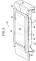
FIG. 3 is a perspective view of an embodiment of a hot gas path component to be placed in a gas turbine; -
FIG. 4 is another perspective view of the hot gas path component to be placed in a gas turbine; and -
FIG. 5 is yet another schematic side view of an exemplary hot gas path component to be placed in a gas turbine. - The detailed description explains embodiments of the invention, together with advantages and features, by way of example with reference to the drawings.
-
FIG. 1 is a schematic diagram of an embodiment of a turbomachine system, such as agas turbine system 100. Thesystem 100 includes acompressor 102, acombustor 104, aturbine 106, ashaft 108 and afuel nozzle 110. In an embodiment, thesystem 100 may include a plurality ofcompressors 102,combustors 104,turbines 106,shafts 108 andfuel nozzles 110. Thecompressor 102 andturbine 106 are coupled by theshaft 108. Theshaft 108 may be a single shaft or a plurality of shaft segments coupled together to formshaft 108. - In an aspect, the
combustor 104 uses liquid and/or gas fuel, such as natural gas or a hydrogen rich synthetic gas, to run the engine. For example,fuel nozzles 110 are in fluid communication with an air supply and afuel supply 112. Thefuel nozzles 110 create an air-fuel mixture, and discharge the air-fuel mixture into thecombustor 104, thereby causing a combustion that creates a hot pressurized exhaust gas. Thecombustor 100 directs the hot pressurized gas through a transition piece into a turbine nozzle (or "stage one nozzle"), and other stages of buckets andnozzles causing turbine 106 rotation. The rotation ofturbine 106 causes theshaft 108 to rotate, thereby compressing the air as it flows into thecompressor 102. In an embodiment, hot gas path components, including, but not limited to, shrouds, diaphragms, nozzles, buckets and transition pieces are located in theturbine 106, where hot gas flow across the components causes creep, oxidation, wear and thermal fatigue of turbine parts. Controlling the temperature of the hot gas path components can reduce distress modes in the components. The efficiency of the gas turbine increases with an increase in firing temperature in theturbine system 100. As the firing temperature increases, the hot gas path components need to be properly cooled to meet service life. Components with improved arrangements for cooling of regions proximate to the hot gas path and methods for making such components are discussed in detail below with reference toFIGS. 2-5 . Although the following discussion primarily focuses on gas turbines, the concepts discussed are not limited to gas turbines. -
FIG. 2 is a schematic side view of an exemplary hotgas path component 200. The hotgas path component 200 has an arrangement that improves cooling along the hot gas path, wherein a brazing or other suitable process is used to form the hotgas path component 200. The hotgas path component 200 includes amember 202 with asurface 204, wherein one ormore channels 206 are formed in thesurface 204. The hotgas path component 200 also includes alayer 208 with afiller material 210 disposed between thelayer 208 and themember 202. During an assembly process, the parts of the hotgas path component 200 are held together by aclamping device 212. An exemplary manufacturing process for the hotgas path component 200 includes the following steps.Channels 206 are formed in themember 202 by a suitable method, such as milling. Thefiller material 210 is then placed on thesurface 204 of themember 202. Thelayer 208 is placed on thefiller material 210 and thesurface 204, thereby enclosingchannels 206. In one embodiment, theclamping devices 212 are configured to compress and hold thelayer 208 andmember 202 together during a heating cycle, such as those used in a brazing process. - Thus, when assembled, a brazing process heats the
member 202,filler material 210 andlayer 208 to a selected temperature for a selected amount of time, wherein the selected temperature is above a melting point of thefiller material 210 and below a melting point of themember 202 and thelayer 208. Exemplary heating cycles for brazing include heating the hot gas path component to a temperature between about 1255 and about 1464 K (1800 and about 2175 degrees Fahrenheit) for about 10 minutes. In some embodiments, the heating cycle is to greater than about 1436 K (2125 degrees Fahrenheit). The heating process melts theexemplary filler material 404, which may include a compound comprising boron, silicon and nickel (e.g., BNi-2, BNi-3, BNi-5). Exemplary materials for themember 202 and thelayer 208 include alloys, such as nickel and cobalt base superalloys. After the heating cycle, the hotgas path component 200 is then cooled, thereby forming a bond between themember 202 and thelayer 208 via the hardenedfiller material 210. Theclamping devices 212 are optionally used to prevent decoupling (or "potato chipping") of portions of the hotgas path component 200 during the heating and cooling cycles. - After assembly and the brazing process, the hot
gas path component 200 is configured to direct a cooling fluid throughchannels 206 to cool the hotgas path component 200 as hot gas passes alongregion 214 during turbine operation. By brazing thelayer 208, a relativelysmall distance 216 is provided between thecooling channel 206 and theregion 214 to be cooled. In an embodiment, thefiller material 210 is a foil layer or a paste applied to thesurface 210, wherein thefiller material 210 provides a bond as it is heated and cooled. In embodiments, themember 202, thesurface 204 and thelayer 208 are curved, thereby enabling a cooling of a curved surface of the exemplary hotgas path component 200. Other shapes or surfaces are also contemplated, such as twisted or wavy surfaces. Exemplary curved hotgas path components 200 include a bucket, a nozzle or other curved member along a hot gas path of a turbine. The depicted arrangement and method for making the hotgas path component 200 provides improved cooling for the component, thereby reducing creep, oxidation and thermal fatigue while improving performance of the turbine. -
FIG. 3 is a perspective view of an embodiment of a hot gas path component to be placed in thegas turbine 100. As depicted, the exemplary hot gas path component is an embodiment of a stage oneshroud 300. Theshroud 300 includes amember 302 with asurface 304 proximate to a hot gas path in theturbine 100. Theshroud 300 also includes asurface 306 proximate to cool fluid and/or air in theturbine 100. To improve cooling of themember 302, one ormore channels 308 are formed in thesurface 304, wherein thechannels 308 are configured to cool thesurface 304 by flowing a cooling fluid. The cooling fluid flows throughholes 310 tochannels 308. Afluid supply 312, such as a chamber and/or a pump, provides the cooling fluid, which may include air, a water solution and/or a gas. Theshroud 300 is configured to interface with a similar adjacent shroud via a seal to be placed in aseal slot 314 ininterface surface 316. In an embodiment, the seal and joinedinterface surface 316 reduces leakage of cool air from thesurface 306 into the hot gas path, thereby providing high temperature hot gas to convert from thermal energy to mechanical energy inside theturbine 100. As will be described in detail with reference toFIG. 4 , thechannels 308 are covered by a layer to form a substantiallyflush surface 304 and enclose thechannels 308. - As depicted, the
channels 308 are configured to control a temperature ofsurface 304. The cooling fluid flows fromfluid supply 312 throughholes 310 intochannels 308, wherein the proximity and configuration ofchannels 308 in relation tosurface 304 provides improved cooling of theshroud 300. In embodiments, the coolingchannels 308 are formed in turbine components proximate a hot gas flow path. Exemplary turbine components along the hot gas path include, but are not limited to, shrouds, nozzles, buckets and diaphragms. For example, thechannels 308 are formed in a surface of sidewall of a nozzle assembly, wherein the channels are configured to cool the sidewall to reduce thermal fatigue for the nozzle assembly. Thechannels 308 may be formed in themember 302 by any suitable method, such as by investment casting during formation of themember 302. Another exemplary technique to form thechannels 308 includes removing material from themember 302 after it has been formed. Removal of material to formchannels 308 may include any suitable method, such as by using a water jet, a mill, a laser, electric discharge machining, any combination thereof or other suitable machining or etching process. As depicted, the coolingchannels 308 are in a U configuration (when line of sight is perpendicular to the surface 304), however, thechannels 308 may be formed in any suitable configuration for cooling including an S, O, Z or other suitable configuration. By using a material removal process, complex and intricate patterns may be used to form thechannels 308 based on component geometry and other application specific factors, thereby improving cooling abilities for the hot gas path component. In addition, any number ofchannels 308 may be formed in themember 302, depending on desired cooling performances and other system constraints. - In embodiments, the cooling fluid is any suitable fluid that cools the turbine components and selected regions of gas flow, such as high temperature and pressure regions of the
shroud 300. For example, the coolingfluid supply 312 is a supply of compressed air from thecompressor 102, wherein the compressed air is diverted from the air supply routed to the combustor. Thus, the supply of compressed air bypasses thecombustor 104 and is used to cool theshroud 300. Accordingly, the improved arrangement ofchannels 308 reduces the amount of compressed air used for cooling by improving cooling of the turbine components and regions near the components. As a result, an increased amount of compressed air is directed to thecombustor 106 for conversion to mechanical output to improve overall performance and efficiency of theturbine 100 while extending turbine component life by reducing thermal fatigue. Further, the disclosed arrangement of theshroud 300 andchannels 308 provides a more uniform temperature distribution alongsurface 304. In aspects, turbine components or parts, including theshroud 300, are formed of stainless steel or an alloy, where the parts may experience creep, oxidation and thermal fatigue if not properly cooled during engine operation. -
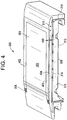
FIG. 4 is another perspective view of theshroud 300. As depicted, theshroud 300 includes a layer 402 (also referred to as "skin layer" "cover member" or "cover piece") disposed on thechannels 308 insurface 304, thereby enclosing thechannels 308. In an embodiment, thelayer 402 is coupled to thesurface 304 afterchannels 308 are formed in themember 302. Thus, theenclosed channels 308 provide improved cooling and reduced thermal fatigue for theshroud 300. In the depicted embodiment, thelayer 402 is a suitable configuration, such as the exemplary U shaped member. Thelayer 402 may be formed from the same or different material as theshroud 300. Exemplary materials for thelayer 402 include alloys, such as nickel or cobalt base superalloys. Further, thelayer 402 may be any suitable geometry or configuration to cover and enclose thechannels 308. Thelayer 402 may also comprise one or more members configured to enclose and/or cover thechannels 308. Thelayer 402 is coupled to thesurface 304 andmember 302 via a suitable bonding method, such as brazing, linear friction welding and diffusion bonding. For example, thelayer 402 is brazed to surface 304 by disposing a brazefoil filler material 404 between the layer andsurface 304. Thefiller material 404,member 302 andlayer 402 are then heated to a selected temperature, wherein thefiller material 404 is melted. Thefiller material 404,member 302 andlayer 300 are then cooled to bond thelayer 402 andmember 302. The heating and cooling processes may be repeated to provide a heating cycle at selected temperatures to bond the parts. The brazing process heats the parts to a melting temperature for thefiller material 404, wherein the temperature is below a melting point of thelayer 402 andmember 302. - With continued reference to
FIG. 4 , the illustratedlayer 300 has athickness 400 of less than about 1.5mm to providecooling channels 308 that are less than about 1.5mm from thesurface 304. In embodiments, thethickness 400 is less than about 1.2mm. In other embodiments, thethickness 400 is less than about 2.5mm. In embodiments, thethickness 400 is less than about .8mm. In yet other embodiments, thethickness 400 ranges from about .4mm to about .6mm. By providing the relativelythin layer 300 to cover and encapsulate thechannels 308, the improved cooling of theshroud 300 extends the life of the hot gas path component. In one embodiment, thelayer 402 is formed to fit the opening forchannels 308 inmember 302, wherein thelayer 402 does not have to have a protruding portion removed. Thus, thelayer 402 is disposed on and coupled to thesurface 304 via brazing or another suitable method, as described above, and provides a substantially uniform profile withsurface 304. -
FIG. 5 is a schematic side view of another exemplary hotgas path component 500. The hotgas path component 500 includes alayer 502 with asurface 504, wherein afiller material 510 is placed between thesurface 504 and amember 508.Channels 506 are formed in a surface 507 of themember 508. In an embodiment, themember 508 is less than about 2.5mm thick. During an assembly process, the parts of the hotgas path component 500 are held together by aclamping device 512. An exemplary brazing process for the hotgas path component 500 includes the following steps.Channels 506 are formed in themember 508 by a suitable method, such as milling. Further, cooling holes 518 are formed by a suitable method, such as drilling. Thefiller material 510 is then placed on the surface 507 of themember 508. Thefiller material 510 is placed on thesurface 504 and themember 508 is then placed on thelayer 502, thereby enclosingchannels 506. Thelayer 502,filler material 510 andmember 508 are heated to a selected temperature for a selected amount of time, wherein the selected temperature is above a melting point of thefiller material 510 and below a melting point of thelayer 502 and themember 508. After the heating cycle, the hotgas path component 500 is then cooled, thereby forming a bond between thelayer 502 and themember 508 via thehardened filler material 510. In an embodiment, thechannels 506 have a relativelysmall distance 516 to a hotgas path region 514 in the turbine system, thereby improving cooling and reducing creep, oxidation and thermal fatigue for the hotgas path component 500 through improved cooling efficiency. - After completion of the brazing process, the component surfaces can be drilled for cooling holes and also coated using a thermal spray process or other coating processes. Hot gas path components in gas turbines are sometimes coated with McrAlY (metallic) bond coats and/or thermal barrier coating (ceramic) top coats. Cooling holes are also drilled in the hot gas path components to provide film cooling fluid/air to cool the part and the coating. In embodiments, after service of the turbine system, the parts are inspected, repaired if necessary and put back in service. Repair typically involves stripping the coating, inspection, welding or brazing to repair the defects such as cracks or loss of material. The parts are then coated and heat treated. Reopening and/or machining of cooling holes on repaired components can be a difficult and tedious process. In the embodiment shown in
FIG. 5 , themember 508 has the cooling holes 518 and coating, themember 508 can be drilled and/or coated prior to brazing it to thecomponent 500, thereby simplifying the repair process. In an embodiment, a service run component can be modified to remove local thermally damaged regions or "hot spots." Cooling channels can be machined while the component is not assembled and themember 508 can be brazed/bonded to form theshroud 500 or other hot gas path component. Themember 508 can be drilled for cooling holes and also coated with metallic and ceramic coatings prior to brazing/bonding to the component. It should be noted that this arrangement and method may be used during a manufacturing or repair process for thecomponent 500. - While the invention has been described in detail in connection with only a limited number of embodiments, it should be readily understood that the invention is not limited to such disclosed embodiments. Accordingly, the invention is not to be seen as limited by the foregoing description, but is only limited by the scope of the appended claims.
Claims (7)
- A method for manufacturing a hot gas path component (200, 300) of a turbine (100), the method comprising the following steps:forming cooling channels (206, 308, 506) in a surface of a member (202, 302, 508) of said hot gas path component (200, 300, 500);further drilling cooling holes (518) in the member; then disposing a layer (208, 402, 502) on the surface (204, 304) of the member (202, 302) to enclose the cooling channels (206, 308), the layer (208, 402) being disposed on a portion of the member (202, 302) to be cooled; andbonding the layer (208, 402) to the surface (204, 304), wherein bonding comprises disposing a braze filler metal between the layer (208, 402) and the surface (204, 304) and heating the layer (208, 402), the member (202, 302) and the braze filler metal to a selected temperature.
- The method of claim 1, wherein the selected temperature comprises a temperature greater than about 1255 K (1800° F).
- The method of claim 1 or 2, wherein the braze filler material comprises a metallic foil.
- The method of any preceding claim, wherein forming cooling channels (206, 308) comprises machining or investment casting the cooling channels (206, 308) in the member (202, 302).
- The method of any preceding claim, wherein forming cooling channels comprises forming the channels using at least one of a water jet, a mill, a laser, and electric discharge machining.
- The method of claim 1, wherein disposing the layer (208, 402) comprises disposing the layer (208, 402) with a thickness (216) less than about 0.8mm.
- The method of claim 1, wherein bonding the layer comprises diffusion bonding the layer and member at a selected temperature.
Applications Claiming Priority (1)
| Application Number | Priority Date | Filing Date | Title |
|---|---|---|---|
| US13/042,167 US8870523B2 (en) | 2011-03-07 | 2011-03-07 | Method for manufacturing a hot gas path component and hot gas path turbine component |
Publications (3)
| Publication Number | Publication Date |
|---|---|
| EP2497906A2 EP2497906A2 (en) | 2012-09-12 |
| EP2497906A3 EP2497906A3 (en) | 2017-08-23 |
| EP2497906B1 true EP2497906B1 (en) | 2021-05-05 |
Family
ID=45808283
Family Applications (1)
| Application Number | Title | Priority Date | Filing Date |
|---|---|---|---|
| EP12158311.6A Active EP2497906B1 (en) | 2011-03-07 | 2012-03-06 | Method for manufacturing a hot gas path component. |
Country Status (4)
| Country | Link |
|---|---|
| US (1) | US8870523B2 (en) |
| EP (1) | EP2497906B1 (en) |
| JP (1) | JP2012184763A (en) |
| CN (2) | CN102678198B (en) |
Families Citing this family (10)
| Publication number | Priority date | Publication date | Assignee | Title |
|---|---|---|---|---|
| US20140170433A1 (en) * | 2012-12-19 | 2014-06-19 | General Electric Company | Components with near-surface cooling microchannels and methods for providing the same |
| US9828872B2 (en) * | 2013-02-07 | 2017-11-28 | General Electric Company | Cooling structure for turbomachine |
| US9713838B2 (en) * | 2013-05-14 | 2017-07-25 | General Electric Company | Static core tie rods |
| CN103700775B (en) | 2013-12-31 | 2017-08-25 | 北京维信诺科技有限公司 | A kind of organic electroluminescence device and preparation method thereof |
| US9757936B2 (en) * | 2014-12-29 | 2017-09-12 | General Electric Company | Hot gas path component |
| US10309252B2 (en) | 2015-12-16 | 2019-06-04 | General Electric Company | System and method for cooling turbine shroud trailing edge |
| US10378380B2 (en) | 2015-12-16 | 2019-08-13 | General Electric Company | Segmented micro-channel for improved flow |
| US10767501B2 (en) * | 2016-04-21 | 2020-09-08 | General Electric Company | Article, component, and method of making a component |
| US10519861B2 (en) | 2016-11-04 | 2019-12-31 | General Electric Company | Transition manifolds for cooling channel connections in cooled structures |
| CN113931702B (en) * | 2020-06-29 | 2024-09-06 | 中国航发商用航空发动机有限责任公司 | Gas turbine, guide blade and guide blade edge plate thereof |
Citations (1)
| Publication number | Priority date | Publication date | Assignee | Title |
|---|---|---|---|---|
| US20100300115A1 (en) * | 2009-06-02 | 2010-12-02 | Mitsubishi Heavy Industries, Ltd. | Process for producing combustor structural member, and combustor structural member, combustor for gas turbine and gas turbine |
Family Cites Families (39)
| Publication number | Priority date | Publication date | Assignee | Title |
|---|---|---|---|---|
| US3644060A (en) * | 1970-06-05 | 1972-02-22 | John K Bryan | Cooled airfoil |
| CA1110173A (en) * | 1978-03-10 | 1981-10-06 | Rodger O. Anderson | Liquid cooled gas turbine buckets |
| JPH0667551B2 (en) * | 1987-05-13 | 1994-08-31 | 三菱重工業株式会社 | Manufacturing method of laminated heat-resistant alloy sheet |
| JP2548733B2 (en) * | 1987-07-07 | 1996-10-30 | 三菱重工業株式会社 | Gas turbine combustion method for diffusion heat treatment |
| JPH0639885B2 (en) | 1988-03-14 | 1994-05-25 | 株式会社日立製作所 | Gas turbine shroud and gas turbine |
| US5169287A (en) | 1991-05-20 | 1992-12-08 | General Electric Company | Shroud cooling assembly for gas turbine engine |
| JPH0727335A (en) * | 1993-07-09 | 1995-01-27 | Hitachi Ltd | Method of manufacturing combustion chamber liner for gas turbine |
| US5516260A (en) * | 1994-10-07 | 1996-05-14 | General Electric Company | Bonded turbine airfuel with floating wall cooling insert |
| US5957657A (en) | 1996-02-26 | 1999-09-28 | Mitisubishi Heavy Industries, Ltd. | Method of forming a cooling air passage in a gas turbine stationary blade shroud |
| JP3202636B2 (en) * | 1997-02-12 | 2001-08-27 | 東北電力株式会社 | Cooling wall structure of steam-cooled combustor |
| US6223524B1 (en) | 1998-01-23 | 2001-05-01 | Diversitech, Inc. | Shrouds for gas turbine engines and methods for making the same |
| JP3702171B2 (en) * | 2000-11-27 | 2005-10-05 | 三菱重工業株式会社 | Manufacturing method of laminated heat-resistant alloy sheet |
| US6528118B2 (en) | 2001-02-06 | 2003-03-04 | General Electric Company | Process for creating structured porosity in thermal barrier coating |
| US6461108B1 (en) | 2001-03-27 | 2002-10-08 | General Electric Company | Cooled thermal barrier coating on a turbine blade tip |
| US6551061B2 (en) * | 2001-03-27 | 2003-04-22 | General Electric Company | Process for forming micro cooling channels inside a thermal barrier coating system without masking material |
| US6565990B2 (en) * | 2001-05-30 | 2003-05-20 | General Electric Company | Bonded niobium silicide and molybdenum silicide composite articles and method of manufacture |
| US6726444B2 (en) * | 2002-03-18 | 2004-04-27 | General Electric Company | Hybrid high temperature articles and method of making |
| US6679680B2 (en) | 2002-03-25 | 2004-01-20 | General Electric Company | Built-up gas turbine component and its fabrication |
| US20040086635A1 (en) | 2002-10-30 | 2004-05-06 | Grossklaus Warren Davis | Method of repairing a stationary shroud of a gas turbine engine using laser cladding |
| US6899518B2 (en) | 2002-12-23 | 2005-05-31 | Pratt & Whitney Canada Corp. | Turbine shroud segment apparatus for reusing cooling air |
| FR2850742B1 (en) * | 2003-01-30 | 2005-09-23 | Snecma Propulsion Solide | ACTIVE COOLING PANEL OF THERMOSTRUCTURAL COMPOSITE MATERIAL AND PROCESS FOR PRODUCING THE SAME |
| US20050044857A1 (en) * | 2003-08-26 | 2005-03-03 | Boris Glezer | Combustor of a gas turbine engine |
| US7487641B2 (en) | 2003-11-14 | 2009-02-10 | The Trustees Of Columbia University In The City Of New York | Microfabricated rankine cycle steam turbine for power generation and methods of making the same |
| US7063503B2 (en) | 2004-04-15 | 2006-06-20 | Pratt & Whitney Canada Corp. | Turbine shroud cooling system |
| US7010921B2 (en) * | 2004-06-01 | 2006-03-14 | General Electric Company | Method and apparatus for cooling combustor liner and transition piece of a gas turbine |
| US7284954B2 (en) | 2005-02-17 | 2007-10-23 | Parker David G | Shroud block with enhanced cooling |
| US7600967B2 (en) | 2005-07-30 | 2009-10-13 | United Technologies Corporation | Stator assembly, module and method for forming a rotary machine |
| DE102005055984A1 (en) | 2005-11-24 | 2007-05-31 | Mtu Aero Engines Gmbh | Process to repair gas turbine jet engine shroud by abrasion of defective material and replacement by cast metal powder |
| US7653994B2 (en) | 2006-03-22 | 2010-02-02 | General Electric Company | Repair of HPT shrouds with sintered preforms |
| US7740442B2 (en) | 2006-11-30 | 2010-06-22 | General Electric Company | Methods and system for cooling integral turbine nozzle and shroud assemblies |
| US7900458B2 (en) | 2007-05-29 | 2011-03-08 | Siemens Energy, Inc. | Turbine airfoils with near surface cooling passages and method of making same |
| US20090053045A1 (en) | 2007-08-22 | 2009-02-26 | General Electric Company | Turbine Shroud for Gas Turbine Assemblies and Processes for Forming the Shroud |
| ATE502720T1 (en) | 2008-04-09 | 2011-04-15 | Alstom Technology Ltd | METHOD FOR REPAIRING THE HOT GAS COMPONENT OF A GAS TURBINE |
| US20100186415A1 (en) * | 2009-01-23 | 2010-07-29 | General Electric Company | Turbulated aft-end liner assembly and related cooling method |
| JP5535495B2 (en) * | 2009-02-25 | 2014-07-02 | 三菱重工業株式会社 | Manufacturing method of laminated heat-resistant alloy sheet |
| US8499566B2 (en) * | 2010-08-12 | 2013-08-06 | General Electric Company | Combustor liner cooling system |
| US8684662B2 (en) | 2010-09-03 | 2014-04-01 | Siemens Energy, Inc. | Ring segment with impingement and convective cooling |
| JP5356345B2 (en) | 2010-09-28 | 2013-12-04 | 株式会社日立製作所 | Gas turbine shroud structure |
| US8673397B2 (en) | 2010-11-10 | 2014-03-18 | General Electric Company | Methods of fabricating and coating a component |
-
2011
- 2011-03-07 US US13/042,167 patent/US8870523B2/en active Active
-
2012
- 2012-03-01 JP JP2012044910A patent/JP2012184763A/en active Pending
- 2012-03-06 EP EP12158311.6A patent/EP2497906B1/en active Active
- 2012-03-07 CN CN201210071591.2A patent/CN102678198B/en active Active
- 2012-03-07 CN CN201610036381.8A patent/CN105649688A/en active Pending
Patent Citations (1)
| Publication number | Priority date | Publication date | Assignee | Title |
|---|---|---|---|---|
| US20100300115A1 (en) * | 2009-06-02 | 2010-12-02 | Mitsubishi Heavy Industries, Ltd. | Process for producing combustor structural member, and combustor structural member, combustor for gas turbine and gas turbine |
Also Published As
| Publication number | Publication date |
|---|---|
| EP2497906A2 (en) | 2012-09-12 |
| CN105649688A (en) | 2016-06-08 |
| US8870523B2 (en) | 2014-10-28 |
| CN102678198A (en) | 2012-09-19 |
| EP2497906A3 (en) | 2017-08-23 |
| CN102678198B (en) | 2016-02-24 |
| US20130139510A1 (en) | 2013-06-06 |
| JP2012184763A (en) | 2012-09-27 |
Similar Documents
| Publication | Publication Date | Title |
|---|---|---|
| EP2497906B1 (en) | Method for manufacturing a hot gas path component. | |
| US10005160B2 (en) | Repair methods for cooled components | |
| EP2876257B1 (en) | Modified turbine component and fabrication method | |
| CA2647767C (en) | Method for repairing a turbine nozzle segment | |
| US8969760B2 (en) | System and method for manufacturing an airfoil | |
| EP2657451B1 (en) | Turbine shroud cooling assembly for a gas turbine system | |
| US8993923B2 (en) | System and method for manufacturing an airfoil | |
| EP1422381B1 (en) | Method of repairing a turbine nozzle segment, and turbine nozzle segment | |
| EP2935951B1 (en) | Closure of cooling holes with a filling agent | |
| JP6400697B2 (en) | Gas turbine engine with liquid metal cooling | |
| US20100325887A1 (en) | Repair method for gas turbine engine components | |
| US20090119919A1 (en) | Components for gas turbine engines and methods for manufacturing components for gas turbine engines | |
| CN106246237A (en) | There are the hot gas path parts of nearly wall air-circulation features | |
| US8632297B2 (en) | Turbine airfoil and method for cooling a turbine airfoil | |
| JP2006170204A (en) | Turbine nozzle segment and repair method thereof | |
| US10252380B2 (en) | Repair or remanufacture of blade platform for a gas turbine engine | |
| EP2412930B1 (en) | Turbine nozzle segment and method of repairing same |
Legal Events
| Date | Code | Title | Description |
|---|---|---|---|
| PUAI | Public reference made under article 153(3) epc to a published international application that has entered the european phase |
Free format text: ORIGINAL CODE: 0009012 |
|
| AK | Designated contracting states |
Kind code of ref document: A2 Designated state(s): AL AT BE BG CH CY CZ DE DK EE ES FI FR GB GR HR HU IE IS IT LI LT LU LV MC MK MT NL NO PL PT RO RS SE SI SK SM TR |
|
| AX | Request for extension of the european patent |
Extension state: BA ME |
|
| PUAL | Search report despatched |
Free format text: ORIGINAL CODE: 0009013 |
|
| AK | Designated contracting states |
Kind code of ref document: A3 Designated state(s): AL AT BE BG CH CY CZ DE DK EE ES FI FR GB GR HR HU IE IS IT LI LT LU LV MC MK MT NL NO PL PT RO RS SE SI SK SM TR |
|
| AX | Request for extension of the european patent |
Extension state: BA ME |
|
| RIC1 | Information provided on ipc code assigned before grant |
Ipc: F01D 9/04 20060101AFI20170717BHEP Ipc: B23K 31/02 20060101ALI20170717BHEP Ipc: F02C 7/00 20060101ALI20170717BHEP |
|
| STAA | Information on the status of an ep patent application or granted ep patent |
Free format text: STATUS: REQUEST FOR EXAMINATION WAS MADE |
|
| 17P | Request for examination filed |
Effective date: 20180223 |
|
| RBV | Designated contracting states (corrected) |
Designated state(s): AL AT BE BG CH CY CZ DE DK EE ES FI FR GB GR HR HU IE IS IT LI LT LU LV MC MK MT NL NO PL PT RO RS SE SI SK SM TR |
|
| STAA | Information on the status of an ep patent application or granted ep patent |
Free format text: STATUS: EXAMINATION IS IN PROGRESS |
|
| 17Q | First examination report despatched |
Effective date: 20190906 |
|
| GRAP | Despatch of communication of intention to grant a patent |
Free format text: ORIGINAL CODE: EPIDOSNIGR1 |
|
| STAA | Information on the status of an ep patent application or granted ep patent |
Free format text: STATUS: GRANT OF PATENT IS INTENDED |
|
| INTG | Intention to grant announced |
Effective date: 20200526 |
|
| GRAJ | Information related to disapproval of communication of intention to grant by the applicant or resumption of examination proceedings by the epo deleted |
Free format text: ORIGINAL CODE: EPIDOSDIGR1 |
|
| STAA | Information on the status of an ep patent application or granted ep patent |
Free format text: STATUS: EXAMINATION IS IN PROGRESS |
|
| GRAP | Despatch of communication of intention to grant a patent |
Free format text: ORIGINAL CODE: EPIDOSNIGR1 |
|
| STAA | Information on the status of an ep patent application or granted ep patent |
Free format text: STATUS: GRANT OF PATENT IS INTENDED |
|
| INTC | Intention to grant announced (deleted) | ||
| INTG | Intention to grant announced |
Effective date: 20201020 |
|
| GRAS | Grant fee paid |
Free format text: ORIGINAL CODE: EPIDOSNIGR3 |
|
| GRAA | (expected) grant |
Free format text: ORIGINAL CODE: 0009210 |
|
| STAA | Information on the status of an ep patent application or granted ep patent |
Free format text: STATUS: THE PATENT HAS BEEN GRANTED |
|
| AK | Designated contracting states |
Kind code of ref document: B1 Designated state(s): AL AT BE BG CH CY CZ DE DK EE ES FI FR GB GR HR HU IE IS IT LI LT LU LV MC MK MT NL NO PL PT RO RS SE SI SK SM TR |
|
| REG | Reference to a national code |
Ref country code: GB Ref legal event code: FG4D |
|
| REG | Reference to a national code |
Ref country code: CH Ref legal event code: EP |
|
| REG | Reference to a national code |
Ref country code: AT Ref legal event code: REF Ref document number: 1390046 Country of ref document: AT Kind code of ref document: T Effective date: 20210515 |
|
| REG | Reference to a national code |
Ref country code: DE Ref legal event code: R096 Ref document number: 602012075450 Country of ref document: DE |
|
| REG | Reference to a national code |
Ref country code: IE Ref legal event code: FG4D |
|
| REG | Reference to a national code |
Ref country code: LT Ref legal event code: MG9D |
|
| REG | Reference to a national code |
Ref country code: AT Ref legal event code: MK05 Ref document number: 1390046 Country of ref document: AT Kind code of ref document: T Effective date: 20210505 |
|
| PG25 | Lapsed in a contracting state [announced via postgrant information from national office to epo] |
Ref country code: FI Free format text: LAPSE BECAUSE OF FAILURE TO SUBMIT A TRANSLATION OF THE DESCRIPTION OR TO PAY THE FEE WITHIN THE PRESCRIBED TIME-LIMIT Effective date: 20210505 Ref country code: LT Free format text: LAPSE BECAUSE OF FAILURE TO SUBMIT A TRANSLATION OF THE DESCRIPTION OR TO PAY THE FEE WITHIN THE PRESCRIBED TIME-LIMIT Effective date: 20210505 Ref country code: AT Free format text: LAPSE BECAUSE OF FAILURE TO SUBMIT A TRANSLATION OF THE DESCRIPTION OR TO PAY THE FEE WITHIN THE PRESCRIBED TIME-LIMIT Effective date: 20210505 Ref country code: BG Free format text: LAPSE BECAUSE OF FAILURE TO SUBMIT A TRANSLATION OF THE DESCRIPTION OR TO PAY THE FEE WITHIN THE PRESCRIBED TIME-LIMIT Effective date: 20210805 Ref country code: HR Free format text: LAPSE BECAUSE OF FAILURE TO SUBMIT A TRANSLATION OF THE DESCRIPTION OR TO PAY THE FEE WITHIN THE PRESCRIBED TIME-LIMIT Effective date: 20210505 |
|
| PG25 | Lapsed in a contracting state [announced via postgrant information from national office to epo] |
Ref country code: IS Free format text: LAPSE BECAUSE OF FAILURE TO SUBMIT A TRANSLATION OF THE DESCRIPTION OR TO PAY THE FEE WITHIN THE PRESCRIBED TIME-LIMIT Effective date: 20210905 Ref country code: LV Free format text: LAPSE BECAUSE OF FAILURE TO SUBMIT A TRANSLATION OF THE DESCRIPTION OR TO PAY THE FEE WITHIN THE PRESCRIBED TIME-LIMIT Effective date: 20210505 Ref country code: GR Free format text: LAPSE BECAUSE OF FAILURE TO SUBMIT A TRANSLATION OF THE DESCRIPTION OR TO PAY THE FEE WITHIN THE PRESCRIBED TIME-LIMIT Effective date: 20210806 Ref country code: SE Free format text: LAPSE BECAUSE OF FAILURE TO SUBMIT A TRANSLATION OF THE DESCRIPTION OR TO PAY THE FEE WITHIN THE PRESCRIBED TIME-LIMIT Effective date: 20210505 Ref country code: RS Free format text: LAPSE BECAUSE OF FAILURE TO SUBMIT A TRANSLATION OF THE DESCRIPTION OR TO PAY THE FEE WITHIN THE PRESCRIBED TIME-LIMIT Effective date: 20210505 Ref country code: PT Free format text: LAPSE BECAUSE OF FAILURE TO SUBMIT A TRANSLATION OF THE DESCRIPTION OR TO PAY THE FEE WITHIN THE PRESCRIBED TIME-LIMIT Effective date: 20210906 Ref country code: NO Free format text: LAPSE BECAUSE OF FAILURE TO SUBMIT A TRANSLATION OF THE DESCRIPTION OR TO PAY THE FEE WITHIN THE PRESCRIBED TIME-LIMIT Effective date: 20210805 Ref country code: PL Free format text: LAPSE BECAUSE OF FAILURE TO SUBMIT A TRANSLATION OF THE DESCRIPTION OR TO PAY THE FEE WITHIN THE PRESCRIBED TIME-LIMIT Effective date: 20210505 Ref country code: ES Free format text: LAPSE BECAUSE OF FAILURE TO SUBMIT A TRANSLATION OF THE DESCRIPTION OR TO PAY THE FEE WITHIN THE PRESCRIBED TIME-LIMIT Effective date: 20210505 |
|
| REG | Reference to a national code |
Ref country code: NL Ref legal event code: MP Effective date: 20210505 |
|
| PG25 | Lapsed in a contracting state [announced via postgrant information from national office to epo] |
Ref country code: NL Free format text: LAPSE BECAUSE OF FAILURE TO SUBMIT A TRANSLATION OF THE DESCRIPTION OR TO PAY THE FEE WITHIN THE PRESCRIBED TIME-LIMIT Effective date: 20210505 |
|
| PG25 | Lapsed in a contracting state [announced via postgrant information from national office to epo] |
Ref country code: SM Free format text: LAPSE BECAUSE OF FAILURE TO SUBMIT A TRANSLATION OF THE DESCRIPTION OR TO PAY THE FEE WITHIN THE PRESCRIBED TIME-LIMIT Effective date: 20210505 Ref country code: SK Free format text: LAPSE BECAUSE OF FAILURE TO SUBMIT A TRANSLATION OF THE DESCRIPTION OR TO PAY THE FEE WITHIN THE PRESCRIBED TIME-LIMIT Effective date: 20210505 Ref country code: EE Free format text: LAPSE BECAUSE OF FAILURE TO SUBMIT A TRANSLATION OF THE DESCRIPTION OR TO PAY THE FEE WITHIN THE PRESCRIBED TIME-LIMIT Effective date: 20210505 Ref country code: CZ Free format text: LAPSE BECAUSE OF FAILURE TO SUBMIT A TRANSLATION OF THE DESCRIPTION OR TO PAY THE FEE WITHIN THE PRESCRIBED TIME-LIMIT Effective date: 20210505 Ref country code: DK Free format text: LAPSE BECAUSE OF FAILURE TO SUBMIT A TRANSLATION OF THE DESCRIPTION OR TO PAY THE FEE WITHIN THE PRESCRIBED TIME-LIMIT Effective date: 20210505 Ref country code: RO Free format text: LAPSE BECAUSE OF FAILURE TO SUBMIT A TRANSLATION OF THE DESCRIPTION OR TO PAY THE FEE WITHIN THE PRESCRIBED TIME-LIMIT Effective date: 20210505 |
|
| REG | Reference to a national code |
Ref country code: DE Ref legal event code: R097 Ref document number: 602012075450 Country of ref document: DE |
|
| PLBE | No opposition filed within time limit |
Free format text: ORIGINAL CODE: 0009261 |
|
| STAA | Information on the status of an ep patent application or granted ep patent |
Free format text: STATUS: NO OPPOSITION FILED WITHIN TIME LIMIT |
|
| 26N | No opposition filed |
Effective date: 20220208 |
|
| PG25 | Lapsed in a contracting state [announced via postgrant information from national office to epo] |
Ref country code: IS Free format text: LAPSE BECAUSE OF FAILURE TO SUBMIT A TRANSLATION OF THE DESCRIPTION OR TO PAY THE FEE WITHIN THE PRESCRIBED TIME-LIMIT Effective date: 20210905 Ref country code: AL Free format text: LAPSE BECAUSE OF FAILURE TO SUBMIT A TRANSLATION OF THE DESCRIPTION OR TO PAY THE FEE WITHIN THE PRESCRIBED TIME-LIMIT Effective date: 20210505 |
|
| PG25 | Lapsed in a contracting state [announced via postgrant information from national office to epo] |
Ref country code: IT Free format text: LAPSE BECAUSE OF FAILURE TO SUBMIT A TRANSLATION OF THE DESCRIPTION OR TO PAY THE FEE WITHIN THE PRESCRIBED TIME-LIMIT Effective date: 20210505 |
|
| PG25 | Lapsed in a contracting state [announced via postgrant information from national office to epo] |
Ref country code: MC Free format text: LAPSE BECAUSE OF FAILURE TO SUBMIT A TRANSLATION OF THE DESCRIPTION OR TO PAY THE FEE WITHIN THE PRESCRIBED TIME-LIMIT Effective date: 20210505 |
|
| REG | Reference to a national code |
Ref country code: CH Ref legal event code: PL |
|
| REG | Reference to a national code |
Ref country code: BE Ref legal event code: MM Effective date: 20220331 |
|
| PG25 | Lapsed in a contracting state [announced via postgrant information from national office to epo] |
Ref country code: LU Free format text: LAPSE BECAUSE OF NON-PAYMENT OF DUE FEES Effective date: 20220306 Ref country code: LI Free format text: LAPSE BECAUSE OF NON-PAYMENT OF DUE FEES Effective date: 20220331 Ref country code: IE Free format text: LAPSE BECAUSE OF NON-PAYMENT OF DUE FEES Effective date: 20220306 Ref country code: CH Free format text: LAPSE BECAUSE OF NON-PAYMENT OF DUE FEES Effective date: 20220331 |
|
| PG25 | Lapsed in a contracting state [announced via postgrant information from national office to epo] |
Ref country code: BE Free format text: LAPSE BECAUSE OF NON-PAYMENT OF DUE FEES Effective date: 20220331 |
|
| P01 | Opt-out of the competence of the unified patent court (upc) registered |
Effective date: 20230522 |
|
| REG | Reference to a national code |
Ref country code: DE Ref legal event code: R081 Ref document number: 602012075450 Country of ref document: DE Owner name: GENERAL ELECTRIC TECHNOLOGY GMBH, CH Free format text: FORMER OWNER: GENERAL ELECTRIC COMPANY, SCHENECTADY, NY, US |
|
| REG | Reference to a national code |
Ref country code: GB Ref legal event code: 732E Free format text: REGISTERED BETWEEN 20240222 AND 20240228 |
|
| PG25 | Lapsed in a contracting state [announced via postgrant information from national office to epo] |
Ref country code: HU Free format text: LAPSE BECAUSE OF FAILURE TO SUBMIT A TRANSLATION OF THE DESCRIPTION OR TO PAY THE FEE WITHIN THE PRESCRIBED TIME-LIMIT; INVALID AB INITIO Effective date: 20120306 |
|
| PG25 | Lapsed in a contracting state [announced via postgrant information from national office to epo] |
Ref country code: MK Free format text: LAPSE BECAUSE OF FAILURE TO SUBMIT A TRANSLATION OF THE DESCRIPTION OR TO PAY THE FEE WITHIN THE PRESCRIBED TIME-LIMIT Effective date: 20210505 Ref country code: CY Free format text: LAPSE BECAUSE OF FAILURE TO SUBMIT A TRANSLATION OF THE DESCRIPTION OR TO PAY THE FEE WITHIN THE PRESCRIBED TIME-LIMIT Effective date: 20210505 |
|
| PG25 | Lapsed in a contracting state [announced via postgrant information from national office to epo] |
Ref country code: TR Free format text: LAPSE BECAUSE OF FAILURE TO SUBMIT A TRANSLATION OF THE DESCRIPTION OR TO PAY THE FEE WITHIN THE PRESCRIBED TIME-LIMIT Effective date: 20210505 |
|
| PG25 | Lapsed in a contracting state [announced via postgrant information from national office to epo] |
Ref country code: MT Free format text: LAPSE BECAUSE OF FAILURE TO SUBMIT A TRANSLATION OF THE DESCRIPTION OR TO PAY THE FEE WITHIN THE PRESCRIBED TIME-LIMIT Effective date: 20210505 |
|
| PGFP | Annual fee paid to national office [announced via postgrant information from national office to epo] |
Ref country code: DE Payment date: 20250211 Year of fee payment: 14 |
|
| PGFP | Annual fee paid to national office [announced via postgrant information from national office to epo] |
Ref country code: FR Payment date: 20250219 Year of fee payment: 14 |
|
| PGFP | Annual fee paid to national office [announced via postgrant information from national office to epo] |
Ref country code: GB Payment date: 20250221 Year of fee payment: 14 |