EP2657451B1 - Turbine shroud cooling assembly for a gas turbine system - Google Patents
Turbine shroud cooling assembly for a gas turbine system Download PDFInfo
- Publication number
- EP2657451B1 EP2657451B1 EP13165262.0A EP13165262A EP2657451B1 EP 2657451 B1 EP2657451 B1 EP 2657451B1 EP 13165262 A EP13165262 A EP 13165262A EP 2657451 B1 EP2657451 B1 EP 2657451B1
- Authority
- EP
- European Patent Office
- Prior art keywords
- turbine
- shroud component
- microchannels
- component
- cooling assembly
- Prior art date
- Legal status (The legal status is an assumption and is not a legal conclusion. Google has not performed a legal analysis and makes no representation as to the accuracy of the status listed.)
- Active
Links
- 238000001816 cooling Methods 0.000 title claims description 55
- 239000000463 material Substances 0.000 claims description 15
- 239000012720 thermal barrier coating Substances 0.000 claims description 6
- 238000007789 sealing Methods 0.000 claims 2
- 239000007787 solid Substances 0.000 claims 1
- 239000007789 gas Substances 0.000 description 36
- 238000000034 method Methods 0.000 description 13
- 239000012809 cooling fluid Substances 0.000 description 11
- 239000000446 fuel Substances 0.000 description 10
- 239000012530 fluid Substances 0.000 description 9
- 230000008569 process Effects 0.000 description 8
- 230000008901 benefit Effects 0.000 description 4
- 239000000203 mixture Substances 0.000 description 3
- MCMNRKCIXSYSNV-UHFFFAOYSA-N Zirconium dioxide Chemical compound O=[Zr]=O MCMNRKCIXSYSNV-UHFFFAOYSA-N 0.000 description 2
- 238000006243 chemical reaction Methods 0.000 description 2
- 238000005530 etching Methods 0.000 description 2
- 238000010304 firing Methods 0.000 description 2
- 238000003754 machining Methods 0.000 description 2
- VNWKTOKETHGBQD-UHFFFAOYSA-N methane Chemical compound C VNWKTOKETHGBQD-UHFFFAOYSA-N 0.000 description 2
- XLYOFNOQVPJJNP-UHFFFAOYSA-N water Substances O XLYOFNOQVPJJNP-UHFFFAOYSA-N 0.000 description 2
- 229910052688 Gadolinium Inorganic materials 0.000 description 1
- UFHFLCQGNIYNRP-UHFFFAOYSA-N Hydrogen Chemical compound [H][H] UFHFLCQGNIYNRP-UHFFFAOYSA-N 0.000 description 1
- 229910052779 Neodymium Inorganic materials 0.000 description 1
- 229910052769 Ytterbium Inorganic materials 0.000 description 1
- 230000004075 alteration Effects 0.000 description 1
- 238000000429 assembly Methods 0.000 description 1
- 230000000712 assembly Effects 0.000 description 1
- 230000004888 barrier function Effects 0.000 description 1
- 230000015572 biosynthetic process Effects 0.000 description 1
- 238000005219 brazing Methods 0.000 description 1
- 230000015556 catabolic process Effects 0.000 description 1
- 239000000919 ceramic Substances 0.000 description 1
- 238000002485 combustion reaction Methods 0.000 description 1
- 238000004891 communication Methods 0.000 description 1
- 238000006731 degradation reaction Methods 0.000 description 1
- 230000009429 distress Effects 0.000 description 1
- 230000000694 effects Effects 0.000 description 1
- 239000001257 hydrogen Substances 0.000 description 1
- 229910052739 hydrogen Inorganic materials 0.000 description 1
- 238000005495 investment casting Methods 0.000 description 1
- 229910052747 lanthanoid Inorganic materials 0.000 description 1
- 150000002602 lanthanoids Chemical class 0.000 description 1
- 229910052746 lanthanum Inorganic materials 0.000 description 1
- 239000007788 liquid Substances 0.000 description 1
- 229910052751 metal Inorganic materials 0.000 description 1
- 239000002184 metal Substances 0.000 description 1
- 239000003345 natural gas Substances 0.000 description 1
- 230000003647 oxidation Effects 0.000 description 1
- 238000007254 oxidation reaction Methods 0.000 description 1
- 238000005240 physical vapour deposition Methods 0.000 description 1
- 230000009467 reduction Effects 0.000 description 1
- 239000007921 spray Substances 0.000 description 1
- 239000000126 substance Substances 0.000 description 1
- 238000006467 substitution reaction Methods 0.000 description 1
- 230000007704 transition Effects 0.000 description 1
- 238000003466 welding Methods 0.000 description 1
- 229910001233 yttria-stabilized zirconia Inorganic materials 0.000 description 1
Images

Classifications
-
- F—MECHANICAL ENGINEERING; LIGHTING; HEATING; WEAPONS; BLASTING
- F01—MACHINES OR ENGINES IN GENERAL; ENGINE PLANTS IN GENERAL; STEAM ENGINES
- F01D—NON-POSITIVE DISPLACEMENT MACHINES OR ENGINES, e.g. STEAM TURBINES
- F01D5/00—Blades; Blade-carrying members; Heating, heat-insulating, cooling or antivibration means on the blades or the members
-
- F—MECHANICAL ENGINEERING; LIGHTING; HEATING; WEAPONS; BLASTING
- F01—MACHINES OR ENGINES IN GENERAL; ENGINE PLANTS IN GENERAL; STEAM ENGINES
- F01D—NON-POSITIVE DISPLACEMENT MACHINES OR ENGINES, e.g. STEAM TURBINES
- F01D25/00—Component parts, details, or accessories, not provided for in, or of interest apart from, other groups
- F01D25/08—Cooling; Heating; Heat-insulation
- F01D25/14—Casings modified therefor
-
- F—MECHANICAL ENGINEERING; LIGHTING; HEATING; WEAPONS; BLASTING
- F01—MACHINES OR ENGINES IN GENERAL; ENGINE PLANTS IN GENERAL; STEAM ENGINES
- F01D—NON-POSITIVE DISPLACEMENT MACHINES OR ENGINES, e.g. STEAM TURBINES
- F01D25/00—Component parts, details, or accessories, not provided for in, or of interest apart from, other groups
- F01D25/24—Casings; Casing parts, e.g. diaphragms, casing fastenings
- F01D25/26—Double casings; Measures against temperature strain in casings
-
- F—MECHANICAL ENGINEERING; LIGHTING; HEATING; WEAPONS; BLASTING
- F01—MACHINES OR ENGINES IN GENERAL; ENGINE PLANTS IN GENERAL; STEAM ENGINES
- F01D—NON-POSITIVE DISPLACEMENT MACHINES OR ENGINES, e.g. STEAM TURBINES
- F01D5/00—Blades; Blade-carrying members; Heating, heat-insulating, cooling or antivibration means on the blades or the members
- F01D5/02—Blade-carrying members, e.g. rotors
- F01D5/08—Heating, heat-insulating or cooling means
- F01D5/081—Cooling fluid being directed on the side of the rotor disc or at the roots of the blades
- F01D5/084—Cooling fluid being directed on the side of the rotor disc or at the roots of the blades the fluid circulating at the periphery of a multistage rotor, e.g. of drum type
-
- F—MECHANICAL ENGINEERING; LIGHTING; HEATING; WEAPONS; BLASTING
- F01—MACHINES OR ENGINES IN GENERAL; ENGINE PLANTS IN GENERAL; STEAM ENGINES
- F01D—NON-POSITIVE DISPLACEMENT MACHINES OR ENGINES, e.g. STEAM TURBINES
- F01D5/00—Blades; Blade-carrying members; Heating, heat-insulating, cooling or antivibration means on the blades or the members
- F01D5/12—Blades
- F01D5/22—Blade-to-blade connections, e.g. for damping vibrations
- F01D5/225—Blade-to-blade connections, e.g. for damping vibrations by shrouding
-
- F—MECHANICAL ENGINEERING; LIGHTING; HEATING; WEAPONS; BLASTING
- F01—MACHINES OR ENGINES IN GENERAL; ENGINE PLANTS IN GENERAL; STEAM ENGINES
- F01D—NON-POSITIVE DISPLACEMENT MACHINES OR ENGINES, e.g. STEAM TURBINES
- F01D11/00—Preventing or minimising internal leakage of working-fluid, e.g. between stages
- F01D11/08—Preventing or minimising internal leakage of working-fluid, e.g. between stages for sealing space between rotor blade tips and stator
-
- F—MECHANICAL ENGINEERING; LIGHTING; HEATING; WEAPONS; BLASTING
- F01—MACHINES OR ENGINES IN GENERAL; ENGINE PLANTS IN GENERAL; STEAM ENGINES
- F01D—NON-POSITIVE DISPLACEMENT MACHINES OR ENGINES, e.g. STEAM TURBINES
- F01D25/00—Component parts, details, or accessories, not provided for in, or of interest apart from, other groups
- F01D25/08—Cooling; Heating; Heat-insulation
- F01D25/12—Cooling
-
- F—MECHANICAL ENGINEERING; LIGHTING; HEATING; WEAPONS; BLASTING
- F01—MACHINES OR ENGINES IN GENERAL; ENGINE PLANTS IN GENERAL; STEAM ENGINES
- F01D—NON-POSITIVE DISPLACEMENT MACHINES OR ENGINES, e.g. STEAM TURBINES
- F01D5/00—Blades; Blade-carrying members; Heating, heat-insulating, cooling or antivibration means on the blades or the members
- F01D5/12—Blades
- F01D5/14—Form or construction
- F01D5/18—Hollow blades, i.e. blades with cooling or heating channels or cavities; Heating, heat-insulating or cooling means on blades
-
- F—MECHANICAL ENGINEERING; LIGHTING; HEATING; WEAPONS; BLASTING
- F05—INDEXING SCHEMES RELATING TO ENGINES OR PUMPS IN VARIOUS SUBCLASSES OF CLASSES F01-F04
- F05D—INDEXING SCHEME FOR ASPECTS RELATING TO NON-POSITIVE-DISPLACEMENT MACHINES OR ENGINES, GAS-TURBINES OR JET-PROPULSION PLANTS
- F05D2260/00—Function
- F05D2260/20—Heat transfer, e.g. cooling
- F05D2260/201—Heat transfer, e.g. cooling by impingement of a fluid
-
- F—MECHANICAL ENGINEERING; LIGHTING; HEATING; WEAPONS; BLASTING
- F05—INDEXING SCHEMES RELATING TO ENGINES OR PUMPS IN VARIOUS SUBCLASSES OF CLASSES F01-F04
- F05D—INDEXING SCHEME FOR ASPECTS RELATING TO NON-POSITIVE-DISPLACEMENT MACHINES OR ENGINES, GAS-TURBINES OR JET-PROPULSION PLANTS
- F05D2260/00—Function
- F05D2260/20—Heat transfer, e.g. cooling
- F05D2260/204—Heat transfer, e.g. cooling by the use of microcircuits
Definitions
- the subject matter disclosed herein relates to gas turbine systems, and more particularly to turbine shroud cooling assemblies for such gas turbine systems.
- Such a turbine shroud cooling assembly having microchannels is for example disclosed in US2011/0044805 A1 .
- a combustor converts the chemical energy of a fuel or an air-fuel mixture into thermal energy.
- the thermal energy is conveyed by a fluid, often compressed air from a compressor, to a turbine where the thermal energy is converted to mechanical energy.
- hot gas is flowed over and through portions of the turbine as a hot gas path. High temperatures along the hot gas path can heat turbine components, causing degradation of components.
- Turbine shrouds are an example of a component that is subjected to the hot gas path and often comprises two separate pieces, such as an inner shroud and an outer shroud.
- the inner shroud and the outer shroud are typically made of two distinct materials that are loosely connected together. The loose connection may be accomplished by sliding the inner shroud onto a rail of the outer shroud or by clipping the inner shroud onto a rail of the outer shroud.
- Such an arrangement allows the outer shroud, which remains cooler during operation, to be of a less expensive material, but results in turbine shroud cooling flow leakage, based on allowance for significantly different growth rates between the hotter, inner shroud and the cooler, outer shroud.
- a turbine shroud cooling assembly for a gas turbine system is provided as set forth in claim 1.
- a turbine shroud cooling assembly for a gas turbine system is provided as set forth in claim 7.
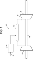
- the gas turbine system 10 includes a compressor 12, a combustor 14, a turbine 16, a shaft 18 and a fuel nozzle 20. It is to be appreciated that one embodiment of the gas turbine system 10 may include a plurality of compressors 12, combustors 14, turbines 16, shafts 18 and fuel nozzles 20. The compressor 12 and the turbine 16 are coupled by the shaft 18.
- the shaft 18 may be a single shaft or a plurality of shaft segments coupled together to form the shaft 18.
- the combustor 14 uses a combustible liquid and/or gas fuel, such as natural gas or a hydrogen rich synthetic gas, to run the gas turbine system 10.
- fuel nozzles 20 are in fluid communication with an air supply and a fuel supply 22.
- the fuel nozzles 20 create an air-fuel mixture, and discharge the air-fuel mixture into the combustor 14, thereby causing a combustion that creates a hot pressurized exhaust gas.
- the combustor 14 directs the hot pressurized gas through a transition piece into a turbine nozzle (or "stage one nozzle"), and other stages of buckets and nozzles causing rotation of the turbine 16 within a turbine casing 24.
- hot gas path components are located in the turbine 16, where hot gas flow across the components causes creep, oxidation, wear and thermal fatigue of turbine components. Controlling the temperature of the hot gas path components can reduce distress modes in the components and the efficiency of the gas turbine system 10 increases with an increase in firing temperature. As the firing temperature increases, the hot gas path components need to be properly cooled to meet service life and to effectively perform intended functionality.
- a shroud assembly is an example of a component disposed in the turbine 16 proximate the turbine casing 24 and subjected to the hot gas path described in detail above.
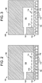
- the turbine shroud cooling assembly 100 includes an inner shroud component 102 with an inner surface 104 proximate to the hot gas path within the turbine 16.
- the turbine shroud cooling assembly 100 also includes an outer shroud component 106 that is generally proximate to a relatively cool fluid and/or air in the turbine 16.
- At least one airway 105 is formed within the outer shroud component 106 for directing the cool fluid and/or air into the turbine shroud cooling assembly 100.
- a plenum 108 within the outer shroud component 106 may be present to ingest and direct the cool fluid and/or air toward a plurality of microchannels 110 disposed within the inner shroud component 102.
- the inner surface 104 comprises a layer disposed proximate the plurality of microchannels 110, thereby enclosing the plurality of microchannels 110 to shield them from direct exposure to the hot gas path.
- the cover layer closest to the channel may comprise a sprayed on bond coat bridging the channel opening, a thin metal layer brazed or welded over one or more of the openings, or any other appropriate method to seal the microchannel(s).
- the layer also comprises a thermal barrier coating ("TBC") and may be any appropriate thermal barrier material.
- TBC may be yttria-stabilized zirconia, and may be applied through a physical vapor deposition process or thermal spray process.
- the TBC may be a ceramic, such as, for example, a thin layer or zirconia modified by other refractory oxides such as oxides formed from Group IV, V and VI elements or oxides modified by Lanthanide series elements such as La, Nd, Gd, Yb and the like.
- the layer may range in thickness from about 0.4 mm to about 1.5 mm.
- the inner shroud component 102 is fixedly connected to the outer shroud component 106, such that a direct, tight engagement is achieved.
- the connection may be made with a variety of available mechanical fasteners or processes, such as bolting, bonding, welding or brazing, for example.
- the fasteners and processes are merely for illustrative purposes and it is to be appreciated that any fastener or process may be employed that provides a direct, tight engagement between the inner shroud component 102 and the outer shroud component 106.
- Reduced leakage of cooling fluid and/or air from the turbine shroud cooling assembly 100 to the hot gas path improves cooling of the turbine shroud cooling assembly 100 and provides a higher temperature gas to convert from thermal energy to mechanical energy in the turbine 16.
- the inner shroud component 102 and the outer shroud component 106 may be formed of two distinct materials ( FIG. 2 ) or a single, uniform material ( FIG. 3 ).
- a single, uniform material is enabled by adequate cooling of the turbine shroud cooling assembly 100, and more particularly adequate cooling of the inner shroud component 102.
- Cooling of the outer shroud component 106 and the inner shroud component 102 is achieved by ingesting an airstream of the cooling fluid and/or air from a fluid supply (not illustrated), such as a chamber and/or a pump.
- the fluid supply provides the cooling fluid, which may include air, a water solution and/or a gas.
- the cooling fluid is any suitable fluid that cools the turbine components and selected regions of gas flow, such as high temperature and pressure regions of the turbine shroud cooling assembly 100.
- the cooling fluid supply is a supply of compressed air from the compressor 12, where the compressed air is diverted from the air supply that is routed to the combustor 14.
- the supply of compressed air bypasses the combustor 14 and is used to cool the turbine shroud cooling assembly 100.
- the cooling fluid flows from the fluid supply through the at least one airway 105 into the plenum 108 of the outer shroud component 106. Subsequently, the cooling fluid, or airstream, is directed into a plurality of microchannel feed holes 112 that lead to the plurality of microchannels 110.
- An impingement plate 114 disposed within the turbine shroud cooling assembly 100 includes a plurality of perforations 116 that provide an impingement cooling jet effect and impinges the cooling fluid toward the microchannel feed holes 112.
- the microchannel feed holes 112 extend in a substantially radial direction from the outer shroud component 106, and more specifically the plenum 108, toward the inner shroud component 102, and more specifically the plurality of microchannels 110.
- the microchannel feed holes 112 may extend in alternative directions and may be aligned at angles, for example, in various configurations. Irrespective of the precise alignment of the plurality of microchannel feed holes 112, the cooling fluid or airstream is directed to the plurality of microchannels 110 formed in the inner shroud component 102 for cooling purposes.
- the plurality of microchannels 110 extend along at least a portion of the inner shroud component 102, and typically along the inner surface 104. Alignment of the plurality of microchannels 110 may be in various directions, including axially and circumferentially, or combinations thereof, with respect to the gas turbine system 10, for example.
- the plurality of microchannels 110 are disposed along the inner surface 104 based on the proximity to the hot gas path, which is particularly susceptible to the issues discussed above associated with relatively hot material temperature. Although described in relation to a turbine shroud, it is to be understood that various other turbine components in close proximity to the hot gas path may benefit from such microchannels. Such components may include, but is not limited to, nozzles, buckets and diaphragms, in addition to the turbine shrouds discussed herein.
- the plurality of microchannels 110 reduces the amount of compressed air used for cooling by improving cooling of the turbine shroud cooling assembly 100, particularly within the inner shroud component 102.
- an increased amount of compressed air is directed to the combustor 14 for conversion to mechanical output to improve overall performance and efficiency of the gas turbine system 10, while extending turbine component life by reducing thermal fatigue.
- the direct, tight alignment of the inner shroud component 102 with the outer shroud component 106 reduces shifting and thermal growth at different rates of the inner shroud component 102 and the outer shroud component 106, which reduces leakage of the cooling fluid to the hot gas path.
- FIG. 4 a second embodiment of the turbine shroud cooling assembly 200 is shown.
- the illustrated embodiment includes similar features as that of the first embodiment described in detail above and will not be repeated in detail, except where necessary. Furthermore, as is the case with additional embodiments described below, similar reference numerals will be employed.
- the plurality of microchannel feed holes 112 are formed in both the outer shroud component 106 and the inner shroud component 102, such that holes line up correspondingly to form the plurality of microchannel feed holes 112, which lead to the plurality of microchannels 110.
- impingement of the cooling fluid, or airstream is imparted onto the outer shroud component 106, in conjunction with impingement toward the plurality of microchannel feed holes 112.
- impingement plate 114 impingement of the cooling fluid, or airstream, is imparted onto the outer shroud component 106, in conjunction with impingement toward the plurality of microchannel feed holes 112.
- the third embodiment focuses zones of impingement on areas that lack the plurality of microchannel feed holes 112. This is accomplished by misaligning the plurality of perforations 116 of the impingement plate 114 with the plurality of microchannel feed holes 112.
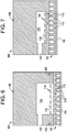
- the fourth embodiment includes at least one secondary attachment fastener 402 that functions as an additional attachment feature for securing the inner shroud component 102 to the outer shroud component 106.
- the secondary attachment fastener 402 is disposed on the inner shroud component 102 and comprises hooks, clips, or the like to engage the outer shroud component 106.
- the second attachment fastener 402 maintains the operable connection.
- FIG. 7 a fifth embodiment of the turbine shroud cooling assembly 500 is shown.
- the plurality of microchannel feed holes 112 are included along a radially outer side of the inner shroud component 102 and brazed material between the inner shroud component 102 and the outer shroud component 106 forms a seal to close the plurality of microchannels 110.
- the plurality of microchannels 110 may be formed by any suitable method, such as by investment casting during formation of the inner shroud component 102.
- Another exemplary technique to form the plurality of microchannels 110 includes removing material from the inner shroud component 102 after it has been formed. Removal of material to form the plurality of microchannels 110 may include any suitable method, such as by using a water jet, a mill, a laser, electric discharge machining, any combination thereof or other suitable machining or etching process. By employing the removal process, complex and intricate patterns may be used to form the plurality of microchannels 110 based on component geometry and other application specific factors, thereby improving cooling abilities for the hot gas path component, such as the turbine shroud cooling assembly 100. In addition, any number of the plurality of microchannels may be formed in the inner shroud component 102, and conceivably the outer shroud component 106, depending on desired cooling performances and other application constraints.
- the plurality of microchannels 110 may be the same or different in size or shape from each other.
- the plurality of microchannels 110 may have widths between approximately 100 microns ( ⁇ m) and 3 millimeters (mm) and depths between approximately 100 ⁇ m and 3 mm, as will be discussed below.
- the plurality of microchannels 110 may have widths and/or depths between approximately 150 ⁇ m and 1.5 mm, between approximately 250 ⁇ m and 1.25 mm, or between approximately 300 ⁇ m and 1 mm.
- the microchannels may have widths and/or depths less than approximately 50, 100, 150, 200, 250, 300, 350, 400, 450, 500, 600, 700, or 750 ⁇ m.
- the plurality of microchannels 110 may be any shape that may be formed using grooving, etching, or similar techniques. Indeed, the plurality of microchannels 110 may have circular, semi-circular, curved, or triangular, rhomboidal cross-sections in addition to or in lieu of the square or rectangular cross-sections as illustrated. The width and depth could vary throughout its length. Therefore, the disclosed flats, slots, grooves, or recesses may have straight or curved geometries consistent with such cross-sections. Moreover, in certain embodiments, the microchannels may have varying cross-sectional areas. Heat transfer enhancements such as turbulators or dimples may be installed in the microchannels as well.
Description
- The subject matter disclosed herein relates to gas turbine systems, and more particularly to turbine shroud cooling assemblies for such gas turbine systems. Such a turbine shroud cooling assembly having microchannels is for example disclosed in
US2011/0044805 A1 . - In gas turbine systems, a combustor converts the chemical energy of a fuel or an air-fuel mixture into thermal energy. The thermal energy is conveyed by a fluid, often compressed air from a compressor, to a turbine where the thermal energy is converted to mechanical energy. As part of the conversion process, hot gas is flowed over and through portions of the turbine as a hot gas path. High temperatures along the hot gas path can heat turbine components, causing degradation of components.
- Turbine shrouds are an example of a component that is subjected to the hot gas path and often comprises two separate pieces, such as an inner shroud and an outer shroud. The inner shroud and the outer shroud are typically made of two distinct materials that are loosely connected together. The loose connection may be accomplished by sliding the inner shroud onto a rail of the outer shroud or by clipping the inner shroud onto a rail of the outer shroud. Such an arrangement allows the outer shroud, which remains cooler during operation, to be of a less expensive material, but results in turbine shroud cooling flow leakage, based on allowance for significantly different growth rates between the hotter, inner shroud and the cooler, outer shroud.
- According to one aspect of the invention, a turbine shroud cooling assembly for a gas turbine system is provided as set forth in claim 1.
- According to another aspect of the invention, a turbine shroud cooling assembly for a gas turbine system is provided as set forth in claim 7.
- These and other advantages and features will become more apparent from the following description taken in conjunction with the drawings.
- The subject matter, which is regarded as the invention, is particularly pointed out and distinctly claimed in the claims at the conclusion of the specification. The foregoing and other features and advantages of the invention are apparent from the following detailed description taken in conjunction with the accompanying drawings in which:
-
FIG. 1 is a schematic illustration of a gas turbine system; -
FIG. 2 is a turbine shroud cooling assembly of a first embodiment having an inner shroud component and an outer shroud component; -
FIG. 3 is a turbine shroud cooling assembly of the first embodiment ofFIG. 2 , wherein the inner shroud component and the outer shroud component are made of a single material; -
FIG. 4 is a turbine shroud cooling assembly of a second embodiment; -
FIG. 5 is a turbine shroud cooling assembly of a third embodiment; -
FIG. 6 is a turbine shroud cooling assembly of a fourth embodiment; and -
FIG. 7 is a turbine shroud cooling assembly of a fifth embodiment. - The detailed description explains embodiments of the invention, together with advantages and features, by way of example with reference to the drawings.
- Referring to
FIG. 1 , a gas turbine system is schematically illustrated withreference numeral 10. Thegas turbine system 10 includes acompressor 12, acombustor 14, aturbine 16, ashaft 18 and afuel nozzle 20. It is to be appreciated that one embodiment of thegas turbine system 10 may include a plurality ofcompressors 12,combustors 14,turbines 16,shafts 18 andfuel nozzles 20. Thecompressor 12 and theturbine 16 are coupled by theshaft 18. Theshaft 18 may be a single shaft or a plurality of shaft segments coupled together to form theshaft 18. - The
combustor 14 uses a combustible liquid and/or gas fuel, such as natural gas or a hydrogen rich synthetic gas, to run thegas turbine system 10. For example,fuel nozzles 20 are in fluid communication with an air supply and afuel supply 22. Thefuel nozzles 20 create an air-fuel mixture, and discharge the air-fuel mixture into thecombustor 14, thereby causing a combustion that creates a hot pressurized exhaust gas. Thecombustor 14 directs the hot pressurized gas through a transition piece into a turbine nozzle (or "stage one nozzle"), and other stages of buckets and nozzles causing rotation of theturbine 16 within aturbine casing 24. Rotation of theturbine 16 causes theshaft 18 to rotate, thereby compressing the air as it flows into thecompressor 12. In an embodiment, hot gas path components are located in theturbine 16, where hot gas flow across the components causes creep, oxidation, wear and thermal fatigue of turbine components. Controlling the temperature of the hot gas path components can reduce distress modes in the components and the efficiency of thegas turbine system 10 increases with an increase in firing temperature. As the firing temperature increases, the hot gas path components need to be properly cooled to meet service life and to effectively perform intended functionality. - Referring to
FIGS. 2 and 3 , a cross-sectional view of a first embodiment of a turbineshroud cooling assembly 100 is shown. A shroud assembly is an example of a component disposed in theturbine 16 proximate theturbine casing 24 and subjected to the hot gas path described in detail above. The turbineshroud cooling assembly 100 includes aninner shroud component 102 with aninner surface 104 proximate to the hot gas path within theturbine 16. The turbineshroud cooling assembly 100 also includes anouter shroud component 106 that is generally proximate to a relatively cool fluid and/or air in theturbine 16. To improve cooling of the overall turbineshroud cooling assembly 100, at least oneairway 105 is formed within theouter shroud component 106 for directing the cool fluid and/or air into the turbineshroud cooling assembly 100. Specifically, aplenum 108 within theouter shroud component 106 may be present to ingest and direct the cool fluid and/or air toward a plurality ofmicrochannels 110 disposed within theinner shroud component 102. Theinner surface 104 comprises a layer disposed proximate the plurality ofmicrochannels 110, thereby enclosing the plurality ofmicrochannels 110 to shield them from direct exposure to the hot gas path. The cover layer closest to the channel may comprise a sprayed on bond coat bridging the channel opening, a thin metal layer brazed or welded over one or more of the openings, or any other appropriate method to seal the microchannel(s). The layer also comprises a thermal barrier coating ("TBC") and may be any appropriate thermal barrier material. For example, the TBC may be yttria-stabilized zirconia, and may be applied through a physical vapor deposition process or thermal spray process. Alternatively, the TBC may be a ceramic, such as, for example, a thin layer or zirconia modified by other refractory oxides such as oxides formed from Group IV, V and VI elements or oxides modified by Lanthanide series elements such as La, Nd, Gd, Yb and the like. The layer may range in thickness from about 0.4 mm to about 1.5 mm. - The
inner shroud component 102 is fixedly connected to theouter shroud component 106, such that a direct, tight engagement is achieved. The connection may be made with a variety of available mechanical fasteners or processes, such as bolting, bonding, welding or brazing, for example. The fasteners and processes are merely for illustrative purposes and it is to be appreciated that any fastener or process may be employed that provides a direct, tight engagement between theinner shroud component 102 and theouter shroud component 106. Reduced leakage of cooling fluid and/or air from the turbineshroud cooling assembly 100 to the hot gas path improves cooling of the turbineshroud cooling assembly 100 and provides a higher temperature gas to convert from thermal energy to mechanical energy in theturbine 16. Such a reduction in leakage is accomplished with a flush connection between theinner shroud component 102 and theouter shroud component 106. Theinner shroud component 102 and theouter shroud component 106 may be formed of two distinct materials (FIG. 2 ) or a single, uniform material (FIG. 3 ). A single, uniform material is enabled by adequate cooling of the turbineshroud cooling assembly 100, and more particularly adequate cooling of theinner shroud component 102. - Cooling of the
outer shroud component 106 and theinner shroud component 102 is achieved by ingesting an airstream of the cooling fluid and/or air from a fluid supply (not illustrated), such as a chamber and/or a pump. The fluid supply provides the cooling fluid, which may include air, a water solution and/or a gas. The cooling fluid is any suitable fluid that cools the turbine components and selected regions of gas flow, such as high temperature and pressure regions of the turbineshroud cooling assembly 100. For example, the cooling fluid supply is a supply of compressed air from thecompressor 12, where the compressed air is diverted from the air supply that is routed to thecombustor 14. Thus, the supply of compressed air bypasses thecombustor 14 and is used to cool the turbineshroud cooling assembly 100. - The cooling fluid flows from the fluid supply through the at least one
airway 105 into theplenum 108 of theouter shroud component 106. Subsequently, the cooling fluid, or airstream, is directed into a plurality ofmicrochannel feed holes 112 that lead to the plurality ofmicrochannels 110. Animpingement plate 114 disposed within the turbineshroud cooling assembly 100 includes a plurality ofperforations 116 that provide an impingement cooling jet effect and impinges the cooling fluid toward themicrochannel feed holes 112. In the illustrated embodiment, themicrochannel feed holes 112 extend in a substantially radial direction from theouter shroud component 106, and more specifically theplenum 108, toward theinner shroud component 102, and more specifically the plurality ofmicrochannels 110. It is to be appreciated that themicrochannel feed holes 112 may extend in alternative directions and may be aligned at angles, for example, in various configurations. Irrespective of the precise alignment of the plurality of microchannel feed holes 112, the cooling fluid or airstream is directed to the plurality ofmicrochannels 110 formed in theinner shroud component 102 for cooling purposes. The plurality ofmicrochannels 110 extend along at least a portion of theinner shroud component 102, and typically along theinner surface 104. Alignment of the plurality ofmicrochannels 110 may be in various directions, including axially and circumferentially, or combinations thereof, with respect to thegas turbine system 10, for example. The plurality ofmicrochannels 110 are disposed along theinner surface 104 based on the proximity to the hot gas path, which is particularly susceptible to the issues discussed above associated with relatively hot material temperature. Although described in relation to a turbine shroud, it is to be understood that various other turbine components in close proximity to the hot gas path may benefit from such microchannels. Such components may include, but is not limited to, nozzles, buckets and diaphragms, in addition to the turbine shrouds discussed herein. - Accordingly, the plurality of
microchannels 110 reduces the amount of compressed air used for cooling by improving cooling of the turbineshroud cooling assembly 100, particularly within theinner shroud component 102. As a result, an increased amount of compressed air is directed to thecombustor 14 for conversion to mechanical output to improve overall performance and efficiency of thegas turbine system 10, while extending turbine component life by reducing thermal fatigue. Additionally, the direct, tight alignment of theinner shroud component 102 with theouter shroud component 106 reduces shifting and thermal growth at different rates of theinner shroud component 102 and theouter shroud component 106, which reduces leakage of the cooling fluid to the hot gas path. - Referring now to
FIG. 4 , a second embodiment of the turbineshroud cooling assembly 200 is shown. The illustrated embodiment, as well as additional embodiments described below, includes similar features as that of the first embodiment described in detail above and will not be repeated in detail, except where necessary. Furthermore, as is the case with additional embodiments described below, similar reference numerals will be employed. The plurality of microchannel feed holes 112 are formed in both theouter shroud component 106 and theinner shroud component 102, such that holes line up correspondingly to form the plurality of microchannel feed holes 112, which lead to the plurality ofmicrochannels 110. In an embodiment employing theimpingement plate 114, impingement of the cooling fluid, or airstream, is imparted onto theouter shroud component 106, in conjunction with impingement toward the plurality of microchannel feed holes 112. Such a configuration enhances cooling of theouter shroud component 106, while also effectively cooling theinner shroud component 102. - Referring now to
FIG. 5 , a third embodiment of the turbineshroud cooling assembly 300 is shown. The third embodiment focuses zones of impingement on areas that lack the plurality of microchannel feed holes 112. This is accomplished by misaligning the plurality ofperforations 116 of theimpingement plate 114 with the plurality of microchannel feed holes 112. - Referring now to
FIG. 6 , a fourth embodiment of the turbineshroud cooling assembly 400 is shown. The fourth embodiment includes at least onesecondary attachment fastener 402 that functions as an additional attachment feature for securing theinner shroud component 102 to theouter shroud component 106. Thesecondary attachment fastener 402 is disposed on theinner shroud component 102 and comprises hooks, clips, or the like to engage theouter shroud component 106. In the event that primary attachments employed to fixedly connect theinner shroud component 102 to theouter shroud component 106 fail, thesecond attachment fastener 402 maintains the operable connection. - Referring now to
FIG. 7 , a fifth embodiment of the turbineshroud cooling assembly 500 is shown. The plurality of microchannel feed holes 112 are included along a radially outer side of theinner shroud component 102 and brazed material between theinner shroud component 102 and theouter shroud component 106 forms a seal to close the plurality ofmicrochannels 110. - With respect to all of the embodiments described above, the plurality of
microchannels 110 may be formed by any suitable method, such as by investment casting during formation of theinner shroud component 102. Another exemplary technique to form the plurality ofmicrochannels 110 includes removing material from theinner shroud component 102 after it has been formed. Removal of material to form the plurality ofmicrochannels 110 may include any suitable method, such as by using a water jet, a mill, a laser, electric discharge machining, any combination thereof or other suitable machining or etching process. By employing the removal process, complex and intricate patterns may be used to form the plurality ofmicrochannels 110 based on component geometry and other application specific factors, thereby improving cooling abilities for the hot gas path component, such as the turbineshroud cooling assembly 100. In addition, any number of the plurality of microchannels may be formed in theinner shroud component 102, and conceivably theouter shroud component 106, depending on desired cooling performances and other application constraints. - The plurality of
microchannels 110 may be the same or different in size or shape from each other. In accordance with certain embodiments, the plurality ofmicrochannels 110 may have widths between approximately 100 microns (µm) and 3 millimeters (mm) and depths between approximately 100 µm and 3 mm, as will be discussed below. For example, the plurality ofmicrochannels 110 may have widths and/or depths between approximately 150 µm and 1.5 mm, between approximately 250 µm and 1.25 mm, or between approximately 300 µm and 1 mm. In certain embodiments, the microchannels may have widths and/or depths less than approximately 50, 100, 150, 200, 250, 300, 350, 400, 450, 500, 600, 700, or 750 µm. While illustrated as square or rectangular in cross-section, the plurality ofmicrochannels 110 may be any shape that may be formed using grooving, etching, or similar techniques. Indeed, the plurality ofmicrochannels 110 may have circular, semi-circular, curved, or triangular, rhomboidal cross-sections in addition to or in lieu of the square or rectangular cross-sections as illustrated. The width and depth could vary throughout its length. Therefore, the disclosed flats, slots, grooves, or recesses may have straight or curved geometries consistent with such cross-sections. Moreover, in certain embodiments, the microchannels may have varying cross-sectional areas. Heat transfer enhancements such as turbulators or dimples may be installed in the microchannels as well. - While the invention has been described in detail in connection with only a limited number of embodiments, it should be readily understood that the invention is not limited to such disclosed embodiments. Rather, the invention can be modified to incorporate any number of variations, alterations, substitutions or equivalent arrangements not heretofore described, but which are commensurate with the scope of the invention. Additionally, while various embodiments of the invention have been described, it is to be understood that aspects of the invention may include only some of the described embodiments. Accordingly, the invention is not to be seen as limited by the foregoing description, but is only limited by the scope of the appended claims.
Claims (12)
- A turbine shroud cooling assembly (100,200,300,400,500) for a gas turbine system (10) comprising:an outer shroud component (106) disposed within a turbine section (16) of the gas turbine system and proximate a turbine section casing (24), wherein the outer shroud component includes at least one airway (105) for ingesting an airstream; andan inner shroud component (102) disposed radially inward of, and directly bonded to, the outer shroud component, wherein the inner shroud component includes a plurality of microchannels (110) extending in at least one of a circumferential direction and an axial direction for cooling the inner shroud component with the airstream from the at least one airway; anda cover disposed proximate an inner surface of the inner shroud component 102;the cover enclosing and sealing the plurality of microchannels from a hot gas path of the gas turbine system, the cover directly defining a radially inner end of the plurality of microchannels, wherein the cover includes a layer proximate the plurality of microchannels comprising a thermal barrier coating having a thickness ranging from 0.4mm to 1.5mm.
- The turbine shroud cooling assembly (100) of claim 1, wherein the outer shroud component comprises a first material and the inner shroud component comprises a second material.
- The turbine shroud cooling assembly (100) of claim 1, wherein the outer shroud component (106) and the inner shroud component (102) are formed of a single material.
- The turbine shroud cooling assembly of any of the preceding claims, further comprising a plurality of microchannel feed holes (112) formed within at least one of the outer shroud component (106) and the inner shroud component (102), wherein the plurality of microchannel feed holes route the airstream to the plurality of microchannels (110).
- The turbine shroud cooling assembly of any of the preceding claims, further comprising an impingement plate (114) having a plurality of perforations (116) for directing the airstream toward the plurality of microchannels (110).
- The turbine shroud cooling assembly (400) of any of the preceding claims, further comprising a secondary attachment feature (402) for operably connecting the inner shroud component (102) to the outer shroud component (106).
- A turbine shroud cooling assembly for a gas turbine system (10) comprising:an outer shroud component (106) disposed within a turbine section (16) of the gas turbine system and proximate a turbine section casing (24);an inner shroud component (102) disposed radially inward of and directly bonded to the outer shroud component (106), wherein the inner shroud component includes a plurality of microchannels (110), wherein the outer shroud component and the inner shroud component are formed of a single material;an impingement plate (114) having a plurality of perforations (116) for directing air toward the plurality of microchannels; anda cover disposed proximate an inner surface of the inner shroud component (120);the cover enclosing and sealing the plurality of microchannels from a hot gas path of the gas turbine system, the cover directly defining a radially inner end of the plurality of microchannels, wherein the cover includes a layer proximate the plurality of microchannels comprising a thermal barrier coating having a thickness ranging from 0.4mm to 1.5mm
- The turbine shroud cooling assembly of claim 7, wherein the outer shroud component (106) and the inner shroud component (102) are integrally formed as a unitary, solid component.
- The turbine shroud cooling assembly of claim 7 or 8, wherein the plurality of microchannels (110) extend in at least one of a circumferential direction and an axial direction.
- The turbine shroud cooling assembly of any of claims 7 to 9, further comprising a plurality of microchannel feed holes (112) formed the inner shroud component (102), wherein the plurality of microchannel feed holes are aligned with the plurality of microchannels (110).
- The turbine shroud cooling assembly of any of claims 7 to 10, wherein the plurality of perforations (116) are aligned with the plurality of microchannel feed holes.
- The turbine shroud cooling assembly of any of claims 7 to 11, wherein the outer shroud component (106) includes at least one airway (105) for ingesting an airstream.
Applications Claiming Priority (1)
| Application Number | Priority Date | Filing Date | Title |
|---|---|---|---|
| US13/456,407 US9127549B2 (en) | 2012-04-26 | 2012-04-26 | Turbine shroud cooling assembly for a gas turbine system |
Publications (3)
| Publication Number | Publication Date |
|---|---|
| EP2657451A2 EP2657451A2 (en) | 2013-10-30 |
| EP2657451A3 EP2657451A3 (en) | 2014-01-01 |
| EP2657451B1 true EP2657451B1 (en) | 2019-06-12 |
Family
ID=48182814
Family Applications (1)
| Application Number | Title | Priority Date | Filing Date |
|---|---|---|---|
| EP13165262.0A Active EP2657451B1 (en) | 2012-04-26 | 2013-04-25 | Turbine shroud cooling assembly for a gas turbine system |
Country Status (5)
| Country | Link |
|---|---|
| US (1) | US9127549B2 (en) |
| EP (1) | EP2657451B1 (en) |
| JP (1) | JP6216146B2 (en) |
| CN (1) | CN103375202B (en) |
| RU (1) | RU2638099C2 (en) |
Families Citing this family (11)
| Publication number | Priority date | Publication date | Assignee | Title |
|---|---|---|---|---|
| US20150198063A1 (en) * | 2014-01-14 | 2015-07-16 | Alstom Technology Ltd | Cooled stator heat shield |
| US9757936B2 (en) | 2014-12-29 | 2017-09-12 | General Electric Company | Hot gas path component |
| US10378380B2 (en) | 2015-12-16 | 2019-08-13 | General Electric Company | Segmented micro-channel for improved flow |
| US10309252B2 (en) | 2015-12-16 | 2019-06-04 | General Electric Company | System and method for cooling turbine shroud trailing edge |
| US10221719B2 (en) | 2015-12-16 | 2019-03-05 | General Electric Company | System and method for cooling turbine shroud |
| US10519861B2 (en) * | 2016-11-04 | 2019-12-31 | General Electric Company | Transition manifolds for cooling channel connections in cooled structures |
| US10634353B2 (en) | 2017-01-12 | 2020-04-28 | General Electric Company | Fuel nozzle assembly with micro channel cooling |
| US10876407B2 (en) * | 2017-02-16 | 2020-12-29 | General Electric Company | Thermal structure for outer diameter mounted turbine blades |
| US10436041B2 (en) | 2017-04-07 | 2019-10-08 | General Electric Company | Shroud assembly for turbine systems |
| US11428160B2 (en) | 2020-12-31 | 2022-08-30 | General Electric Company | Gas turbine engine with interdigitated turbine and gear assembly |
| EP4105449A1 (en) * | 2021-06-18 | 2022-12-21 | Raytheon Technologies Corporation | Hybrid bonded configuration for blade outer airseal (boas) |
Citations (2)
| Publication number | Priority date | Publication date | Assignee | Title |
|---|---|---|---|---|
| US5538393A (en) * | 1995-01-31 | 1996-07-23 | United Technologies Corporation | Turbine shroud segment with serpentine cooling channels having a bend passage |
| US20110044805A1 (en) * | 2009-08-24 | 2011-02-24 | Mitsubishi Heavy Industries, Ltd. | Cooling system of ring segment and gas turbine |
Family Cites Families (35)
| Publication number | Priority date | Publication date | Assignee | Title |
|---|---|---|---|---|
| JPH0639885B2 (en) | 1988-03-14 | 1994-05-25 | 株式会社日立製作所 | Gas turbine shroud and gas turbine |
| US5169287A (en) * | 1991-05-20 | 1992-12-08 | General Electric Company | Shroud cooling assembly for gas turbine engine |
| US5957657A (en) | 1996-02-26 | 1999-09-28 | Mitisubishi Heavy Industries, Ltd. | Method of forming a cooling air passage in a gas turbine stationary blade shroud |
| US5738490A (en) * | 1996-05-20 | 1998-04-14 | Pratt & Whitney Canada, Inc. | Gas turbine engine shroud seals |
| FR2766517B1 (en) * | 1997-07-24 | 1999-09-03 | Snecma | DEVICE FOR VENTILATION OF A TURBOMACHINE RING |
| US6223524B1 (en) | 1998-01-23 | 2001-05-01 | Diversitech, Inc. | Shrouds for gas turbine engines and methods for making the same |
| US6528118B2 (en) | 2001-02-06 | 2003-03-04 | General Electric Company | Process for creating structured porosity in thermal barrier coating |
| US6461108B1 (en) | 2001-03-27 | 2002-10-08 | General Electric Company | Cooled thermal barrier coating on a turbine blade tip |
| US6679680B2 (en) | 2002-03-25 | 2004-01-20 | General Electric Company | Built-up gas turbine component and its fabrication |
| US20040086635A1 (en) | 2002-10-30 | 2004-05-06 | Grossklaus Warren Davis | Method of repairing a stationary shroud of a gas turbine engine using laser cladding |
| US6899518B2 (en) | 2002-12-23 | 2005-05-31 | Pratt & Whitney Canada Corp. | Turbine shroud segment apparatus for reusing cooling air |
| FR2857406B1 (en) * | 2003-07-10 | 2005-09-30 | Snecma Moteurs | COOLING THE TURBINE RINGS |
| US7487641B2 (en) | 2003-11-14 | 2009-02-10 | The Trustees Of Columbia University In The City Of New York | Microfabricated rankine cycle steam turbine for power generation and methods of making the same |
| US7063503B2 (en) | 2004-04-15 | 2006-06-20 | Pratt & Whitney Canada Corp. | Turbine shroud cooling system |
| US7306424B2 (en) * | 2004-12-29 | 2007-12-11 | United Technologies Corporation | Blade outer seal with micro axial flow cooling system |
| US7217089B2 (en) * | 2005-01-14 | 2007-05-15 | Pratt & Whitney Canada Corp. | Gas turbine engine shroud sealing arrangement |
| US7510370B2 (en) * | 2005-02-01 | 2009-03-31 | Honeywell International Inc. | Turbine blade tip and shroud clearance control coating system |
| US7284954B2 (en) | 2005-02-17 | 2007-10-23 | Parker David G | Shroud block with enhanced cooling |
| US7600967B2 (en) | 2005-07-30 | 2009-10-13 | United Technologies Corporation | Stator assembly, module and method for forming a rotary machine |
| US7387488B2 (en) * | 2005-08-05 | 2008-06-17 | General Electric Company | Cooled turbine shroud |
| DE102005055984A1 (en) | 2005-11-24 | 2007-05-31 | Mtu Aero Engines Gmbh | Process to repair gas turbine jet engine shroud by abrasion of defective material and replacement by cast metal powder |
| US7653994B2 (en) | 2006-03-22 | 2010-02-02 | General Electric Company | Repair of HPT shrouds with sintered preforms |
| US7740442B2 (en) * | 2006-11-30 | 2010-06-22 | General Electric Company | Methods and system for cooling integral turbine nozzle and shroud assemblies |
| US7597533B1 (en) * | 2007-01-26 | 2009-10-06 | Florida Turbine Technologies, Inc. | BOAS with multi-metering diffusion cooling |
| FR2914017B1 (en) * | 2007-03-20 | 2011-07-08 | Snecma | SEALING DEVICE FOR A COOLING CIRCUIT, INTER-TURBINE HOUSING BEING EQUIPPED AND TURBOREACTOR COMPRISING THE SAME |
| US7900458B2 (en) | 2007-05-29 | 2011-03-08 | Siemens Energy, Inc. | Turbine airfoils with near surface cooling passages and method of making same |
| US20090053045A1 (en) | 2007-08-22 | 2009-02-26 | General Electric Company | Turbine Shroud for Gas Turbine Assemblies and Processes for Forming the Shroud |
| EP2108477B1 (en) | 2008-04-09 | 2011-03-23 | Alstom Technology Ltd | Gas turbine hot gas component repair method |
| US8556575B2 (en) * | 2010-03-26 | 2013-10-15 | United Technologies Corporation | Blade outer seal for a gas turbine engine |
| US8651805B2 (en) * | 2010-04-22 | 2014-02-18 | General Electric Company | Hot gas path component cooling system |
| US8647053B2 (en) * | 2010-08-09 | 2014-02-11 | Siemens Energy, Inc. | Cooling arrangement for a turbine component |
| US8499566B2 (en) | 2010-08-12 | 2013-08-06 | General Electric Company | Combustor liner cooling system |
| US8684662B2 (en) | 2010-09-03 | 2014-04-01 | Siemens Energy, Inc. | Ring segment with impingement and convective cooling |
| JP5356345B2 (en) | 2010-09-28 | 2013-12-04 | 株式会社日立製作所 | Gas turbine shroud structure |
| US8673397B2 (en) | 2010-11-10 | 2014-03-18 | General Electric Company | Methods of fabricating and coating a component |
-
2012
- 2012-04-26 US US13/456,407 patent/US9127549B2/en active Active
-
2013
- 2013-04-24 JP JP2013090841A patent/JP6216146B2/en active Active
- 2013-04-25 RU RU2013119150A patent/RU2638099C2/en active
- 2013-04-25 EP EP13165262.0A patent/EP2657451B1/en active Active
- 2013-04-26 CN CN201310149413.1A patent/CN103375202B/en active Active
Patent Citations (2)
| Publication number | Priority date | Publication date | Assignee | Title |
|---|---|---|---|---|
| US5538393A (en) * | 1995-01-31 | 1996-07-23 | United Technologies Corporation | Turbine shroud segment with serpentine cooling channels having a bend passage |
| US20110044805A1 (en) * | 2009-08-24 | 2011-02-24 | Mitsubishi Heavy Industries, Ltd. | Cooling system of ring segment and gas turbine |
Also Published As
| Publication number | Publication date |
|---|---|
| JP6216146B2 (en) | 2017-10-18 |
| EP2657451A2 (en) | 2013-10-30 |
| US20130287546A1 (en) | 2013-10-31 |
| RU2013119150A (en) | 2014-10-27 |
| CN103375202A (en) | 2013-10-30 |
| EP2657451A3 (en) | 2014-01-01 |
| RU2638099C2 (en) | 2017-12-11 |
| JP2013227979A (en) | 2013-11-07 |
| CN103375202B (en) | 2017-04-26 |
| US9127549B2 (en) | 2015-09-08 |
Similar Documents
| Publication | Publication Date | Title |
|---|---|---|
| EP2657451B1 (en) | Turbine shroud cooling assembly for a gas turbine system | |
| EP3736409B1 (en) | Turbine shroud assembly with a plurality of shroud segments having internal cooling passages | |
| JP5639852B2 (en) | Heat shield device and replacement method thereof | |
| CN108019239B (en) | Interwoven near-surface cooled channels for a cooled structure | |
| US9708915B2 (en) | Hot gas components with compound angled cooling features and methods of manufacture | |
| EP2615254B1 (en) | Gas turbine stator assembly having abuting components with slots for receiving a sealing member | |
| JP2011163344A (en) | Heat shield | |
| EP2615255B1 (en) | Turbine assembly and method for controlling a temperature of an assembly | |
| CN106907194B (en) | Segmented microchannels for improved flow | |
| US20090285671A1 (en) | Vortex cooled turbine blade outer air seal for a turbine engine | |
| CN102434224B (en) | Turbine airfoil and method for cooling a turbine airfoil | |
| US11927110B2 (en) | Component for a turbine engine with a cooling hole | |
| EP3470628B1 (en) | Aft frame assembly for gas turbine transition piece | |
| US9464536B2 (en) | Sealing arrangement for a turbine system and method of sealing between two turbine components | |
| JP6873670B2 (en) | System and gas turbine engine for cooling turbine shrouds | |
| EP3228821A1 (en) | System and method for cooling trailing edge and/or leading edge of hot gas flow path component | |
| EP2669476A2 (en) | Cooling assembly for a bucket of a turbine system and corresponding method of cooling | |
| US10760431B2 (en) | Component for a turbine engine with a cooling hole | |
| US20200103114A1 (en) | Combustor cap assembly with cooling microchannels | |
| US20160265364A1 (en) | Turbine blade |
Legal Events
| Date | Code | Title | Description |
|---|---|---|---|
| PUAI | Public reference made under article 153(3) epc to a published international application that has entered the european phase |
Free format text: ORIGINAL CODE: 0009012 |
|
| AK | Designated contracting states |
Kind code of ref document: A2 Designated state(s): AL AT BE BG CH CY CZ DE DK EE ES FI FR GB GR HR HU IE IS IT LI LT LU LV MC MK MT NL NO PL PT RO RS SE SI SK SM TR |
|
| AX | Request for extension of the european patent |
Extension state: BA ME |
|
| PUAL | Search report despatched |
Free format text: ORIGINAL CODE: 0009013 |
|
| AK | Designated contracting states |
Kind code of ref document: A3 Designated state(s): AL AT BE BG CH CY CZ DE DK EE ES FI FR GB GR HR HU IE IS IT LI LT LU LV MC MK MT NL NO PL PT RO RS SE SI SK SM TR |
|
| AX | Request for extension of the european patent |
Extension state: BA ME |
|
| RIC1 | Information provided on ipc code assigned before grant |
Ipc: F01D 25/14 20060101ALI20131128BHEP Ipc: F01D 5/08 20060101ALI20131128BHEP Ipc: F01D 5/00 20060101AFI20131128BHEP Ipc: F01D 25/12 20060101ALI20131128BHEP Ipc: F01D 25/26 20060101ALI20131128BHEP Ipc: F01D 5/22 20060101ALI20131128BHEP |
|
| 17P | Request for examination filed |
Effective date: 20140701 |
|
| RBV | Designated contracting states (corrected) |
Designated state(s): AL AT BE BG CH CY CZ DE DK EE ES FI FR GB GR HR HU IE IS IT LI LT LU LV MC MK MT NL NO PL PT RO RS SE SI SK SM TR |
|
| STAA | Information on the status of an ep patent application or granted ep patent |
Free format text: STATUS: EXAMINATION IS IN PROGRESS |
|
| 17Q | First examination report despatched |
Effective date: 20180523 |
|
| GRAP | Despatch of communication of intention to grant a patent |
Free format text: ORIGINAL CODE: EPIDOSNIGR1 |
|
| STAA | Information on the status of an ep patent application or granted ep patent |
Free format text: STATUS: GRANT OF PATENT IS INTENDED |
|
| INTG | Intention to grant announced |
Effective date: 20190227 |
|
| RIN1 | Information on inventor provided before grant (corrected) |
Inventor name: SCHICK, DAVID EDWARD Inventor name: WEBER, DAVID WAYNE Inventor name: LACY, BENJAMIN PAUL |
|
| GRAS | Grant fee paid |
Free format text: ORIGINAL CODE: EPIDOSNIGR3 |
|
| GRAA | (expected) grant |
Free format text: ORIGINAL CODE: 0009210 |
|
| STAA | Information on the status of an ep patent application or granted ep patent |
Free format text: STATUS: THE PATENT HAS BEEN GRANTED |
|
| AK | Designated contracting states |
Kind code of ref document: B1 Designated state(s): AL AT BE BG CH CY CZ DE DK EE ES FI FR GB GR HR HU IE IS IT LI LT LU LV MC MK MT NL NO PL PT RO RS SE SI SK SM TR |
|
| REG | Reference to a national code |
Ref country code: GB Ref legal event code: FG4D |
|
| REG | Reference to a national code |
Ref country code: CH Ref legal event code: EP |
|
| REG | Reference to a national code |
Ref country code: AT Ref legal event code: REF Ref document number: 1142772 Country of ref document: AT Kind code of ref document: T Effective date: 20190615 |
|
| REG | Reference to a national code |
Ref country code: IE Ref legal event code: FG4D |
|
| REG | Reference to a national code |
Ref country code: DE Ref legal event code: R096 Ref document number: 602013056422 Country of ref document: DE |
|
| REG | Reference to a national code |
Ref country code: NL Ref legal event code: MP Effective date: 20190612 |
|
| REG | Reference to a national code |
Ref country code: LT Ref legal event code: MG4D |
|
| PG25 | Lapsed in a contracting state [announced via postgrant information from national office to epo] |
Ref country code: SE Free format text: LAPSE BECAUSE OF FAILURE TO SUBMIT A TRANSLATION OF THE DESCRIPTION OR TO PAY THE FEE WITHIN THE PRESCRIBED TIME-LIMIT Effective date: 20190612 Ref country code: LT Free format text: LAPSE BECAUSE OF FAILURE TO SUBMIT A TRANSLATION OF THE DESCRIPTION OR TO PAY THE FEE WITHIN THE PRESCRIBED TIME-LIMIT Effective date: 20190612 Ref country code: ES Free format text: LAPSE BECAUSE OF FAILURE TO SUBMIT A TRANSLATION OF THE DESCRIPTION OR TO PAY THE FEE WITHIN THE PRESCRIBED TIME-LIMIT Effective date: 20190612 Ref country code: AL Free format text: LAPSE BECAUSE OF FAILURE TO SUBMIT A TRANSLATION OF THE DESCRIPTION OR TO PAY THE FEE WITHIN THE PRESCRIBED TIME-LIMIT Effective date: 20190612 Ref country code: HR Free format text: LAPSE BECAUSE OF FAILURE TO SUBMIT A TRANSLATION OF THE DESCRIPTION OR TO PAY THE FEE WITHIN THE PRESCRIBED TIME-LIMIT Effective date: 20190612 Ref country code: NO Free format text: LAPSE BECAUSE OF FAILURE TO SUBMIT A TRANSLATION OF THE DESCRIPTION OR TO PAY THE FEE WITHIN THE PRESCRIBED TIME-LIMIT Effective date: 20190912 Ref country code: FI Free format text: LAPSE BECAUSE OF FAILURE TO SUBMIT A TRANSLATION OF THE DESCRIPTION OR TO PAY THE FEE WITHIN THE PRESCRIBED TIME-LIMIT Effective date: 20190612 |
|
| PG25 | Lapsed in a contracting state [announced via postgrant information from national office to epo] |
Ref country code: GR Free format text: LAPSE BECAUSE OF FAILURE TO SUBMIT A TRANSLATION OF THE DESCRIPTION OR TO PAY THE FEE WITHIN THE PRESCRIBED TIME-LIMIT Effective date: 20190913 Ref country code: RS Free format text: LAPSE BECAUSE OF FAILURE TO SUBMIT A TRANSLATION OF THE DESCRIPTION OR TO PAY THE FEE WITHIN THE PRESCRIBED TIME-LIMIT Effective date: 20190612 Ref country code: BG Free format text: LAPSE BECAUSE OF FAILURE TO SUBMIT A TRANSLATION OF THE DESCRIPTION OR TO PAY THE FEE WITHIN THE PRESCRIBED TIME-LIMIT Effective date: 20190912 Ref country code: LV Free format text: LAPSE BECAUSE OF FAILURE TO SUBMIT A TRANSLATION OF THE DESCRIPTION OR TO PAY THE FEE WITHIN THE PRESCRIBED TIME-LIMIT Effective date: 20190612 |
|
| REG | Reference to a national code |
Ref country code: AT Ref legal event code: MK05 Ref document number: 1142772 Country of ref document: AT Kind code of ref document: T Effective date: 20190612 |
|
| PG25 | Lapsed in a contracting state [announced via postgrant information from national office to epo] |
Ref country code: NL Free format text: LAPSE BECAUSE OF FAILURE TO SUBMIT A TRANSLATION OF THE DESCRIPTION OR TO PAY THE FEE WITHIN THE PRESCRIBED TIME-LIMIT Effective date: 20190612 Ref country code: EE Free format text: LAPSE BECAUSE OF FAILURE TO SUBMIT A TRANSLATION OF THE DESCRIPTION OR TO PAY THE FEE WITHIN THE PRESCRIBED TIME-LIMIT Effective date: 20190612 Ref country code: AT Free format text: LAPSE BECAUSE OF FAILURE TO SUBMIT A TRANSLATION OF THE DESCRIPTION OR TO PAY THE FEE WITHIN THE PRESCRIBED TIME-LIMIT Effective date: 20190612 Ref country code: SK Free format text: LAPSE BECAUSE OF FAILURE TO SUBMIT A TRANSLATION OF THE DESCRIPTION OR TO PAY THE FEE WITHIN THE PRESCRIBED TIME-LIMIT Effective date: 20190612 Ref country code: CZ Free format text: LAPSE BECAUSE OF FAILURE TO SUBMIT A TRANSLATION OF THE DESCRIPTION OR TO PAY THE FEE WITHIN THE PRESCRIBED TIME-LIMIT Effective date: 20190612 Ref country code: PT Free format text: LAPSE BECAUSE OF FAILURE TO SUBMIT A TRANSLATION OF THE DESCRIPTION OR TO PAY THE FEE WITHIN THE PRESCRIBED TIME-LIMIT Effective date: 20191014 Ref country code: RO Free format text: LAPSE BECAUSE OF FAILURE TO SUBMIT A TRANSLATION OF THE DESCRIPTION OR TO PAY THE FEE WITHIN THE PRESCRIBED TIME-LIMIT Effective date: 20190612 |
|
| PG25 | Lapsed in a contracting state [announced via postgrant information from national office to epo] |
Ref country code: IS Free format text: LAPSE BECAUSE OF FAILURE TO SUBMIT A TRANSLATION OF THE DESCRIPTION OR TO PAY THE FEE WITHIN THE PRESCRIBED TIME-LIMIT Effective date: 20191012 Ref country code: SM Free format text: LAPSE BECAUSE OF FAILURE TO SUBMIT A TRANSLATION OF THE DESCRIPTION OR TO PAY THE FEE WITHIN THE PRESCRIBED TIME-LIMIT Effective date: 20190612 |
|
| REG | Reference to a national code |
Ref country code: DE Ref legal event code: R097 Ref document number: 602013056422 Country of ref document: DE |
|
| PG25 | Lapsed in a contracting state [announced via postgrant information from national office to epo] |
Ref country code: TR Free format text: LAPSE BECAUSE OF FAILURE TO SUBMIT A TRANSLATION OF THE DESCRIPTION OR TO PAY THE FEE WITHIN THE PRESCRIBED TIME-LIMIT Effective date: 20190612 |
|
| PLBE | No opposition filed within time limit |
Free format text: ORIGINAL CODE: 0009261 |
|
| STAA | Information on the status of an ep patent application or granted ep patent |
Free format text: STATUS: NO OPPOSITION FILED WITHIN TIME LIMIT |
|
| PG25 | Lapsed in a contracting state [announced via postgrant information from national office to epo] |
Ref country code: PL Free format text: LAPSE BECAUSE OF FAILURE TO SUBMIT A TRANSLATION OF THE DESCRIPTION OR TO PAY THE FEE WITHIN THE PRESCRIBED TIME-LIMIT Effective date: 20190612 Ref country code: DK Free format text: LAPSE BECAUSE OF FAILURE TO SUBMIT A TRANSLATION OF THE DESCRIPTION OR TO PAY THE FEE WITHIN THE PRESCRIBED TIME-LIMIT Effective date: 20190612 |
|
| 26N | No opposition filed |
Effective date: 20200313 |
|
| PG25 | Lapsed in a contracting state [announced via postgrant information from national office to epo] |
Ref country code: IS Free format text: LAPSE BECAUSE OF FAILURE TO SUBMIT A TRANSLATION OF THE DESCRIPTION OR TO PAY THE FEE WITHIN THE PRESCRIBED TIME-LIMIT Effective date: 20200224 Ref country code: SI Free format text: LAPSE BECAUSE OF FAILURE TO SUBMIT A TRANSLATION OF THE DESCRIPTION OR TO PAY THE FEE WITHIN THE PRESCRIBED TIME-LIMIT Effective date: 20190612 |
|
| PG2D | Information on lapse in contracting state deleted |
Ref country code: IS |
|
| PG25 | Lapsed in a contracting state [announced via postgrant information from national office to epo] |
Ref country code: MC Free format text: LAPSE BECAUSE OF FAILURE TO SUBMIT A TRANSLATION OF THE DESCRIPTION OR TO PAY THE FEE WITHIN THE PRESCRIBED TIME-LIMIT Effective date: 20190612 |
|
| REG | Reference to a national code |
Ref country code: CH Ref legal event code: PL |
|
| PG25 | Lapsed in a contracting state [announced via postgrant information from national office to epo] |
Ref country code: LU Free format text: LAPSE BECAUSE OF NON-PAYMENT OF DUE FEES Effective date: 20200425 Ref country code: FR Free format text: LAPSE BECAUSE OF NON-PAYMENT OF DUE FEES Effective date: 20200430 Ref country code: LI Free format text: LAPSE BECAUSE OF NON-PAYMENT OF DUE FEES Effective date: 20200430 Ref country code: CH Free format text: LAPSE BECAUSE OF NON-PAYMENT OF DUE FEES Effective date: 20200430 |
|
| REG | Reference to a national code |
Ref country code: BE Ref legal event code: MM Effective date: 20200430 |
|
| PG25 | Lapsed in a contracting state [announced via postgrant information from national office to epo] |
Ref country code: BE Free format text: LAPSE BECAUSE OF NON-PAYMENT OF DUE FEES Effective date: 20200430 |
|
| GBPC | Gb: european patent ceased through non-payment of renewal fee |
Effective date: 20200425 |
|
| PG25 | Lapsed in a contracting state [announced via postgrant information from national office to epo] |
Ref country code: GB Free format text: LAPSE BECAUSE OF NON-PAYMENT OF DUE FEES Effective date: 20200425 Ref country code: IE Free format text: LAPSE BECAUSE OF NON-PAYMENT OF DUE FEES Effective date: 20200425 |
|
| PG25 | Lapsed in a contracting state [announced via postgrant information from national office to epo] |
Ref country code: MT Free format text: LAPSE BECAUSE OF FAILURE TO SUBMIT A TRANSLATION OF THE DESCRIPTION OR TO PAY THE FEE WITHIN THE PRESCRIBED TIME-LIMIT Effective date: 20190612 Ref country code: CY Free format text: LAPSE BECAUSE OF FAILURE TO SUBMIT A TRANSLATION OF THE DESCRIPTION OR TO PAY THE FEE WITHIN THE PRESCRIBED TIME-LIMIT Effective date: 20190612 |
|
| PG25 | Lapsed in a contracting state [announced via postgrant information from national office to epo] |
Ref country code: MK Free format text: LAPSE BECAUSE OF FAILURE TO SUBMIT A TRANSLATION OF THE DESCRIPTION OR TO PAY THE FEE WITHIN THE PRESCRIBED TIME-LIMIT Effective date: 20190612 |
|
| PGFP | Annual fee paid to national office [announced via postgrant information from national office to epo] |
Ref country code: IT Payment date: 20230322 Year of fee payment: 11 |
|
| PGFP | Annual fee paid to national office [announced via postgrant information from national office to epo] |
Ref country code: DE Payment date: 20230321 Year of fee payment: 11 |
|
| REG | Reference to a national code |
Ref country code: DE Ref legal event code: R082 Ref document number: 602013056422 Country of ref document: DE Ref country code: DE Ref legal event code: R081 Ref document number: 602013056422 Country of ref document: DE Owner name: GENERAL ELECTRIC TECHNOLOGY GMBH, CH Free format text: FORMER OWNER: GENERAL ELECTRIC COMPANY, SCHENECTADY, NY, US |