EP3821721A1 - Method and machine for making pieces of a multilayer, cylindrical tubular rod used to make substantially cylindrical smokers articles - Google Patents
Method and machine for making pieces of a multilayer, cylindrical tubular rod used to make substantially cylindrical smokers articles Download PDFInfo
- Publication number
- EP3821721A1 EP3821721A1 EP20207451.4A EP20207451A EP3821721A1 EP 3821721 A1 EP3821721 A1 EP 3821721A1 EP 20207451 A EP20207451 A EP 20207451A EP 3821721 A1 EP3821721 A1 EP 3821721A1
- Authority
- EP
- European Patent Office
- Prior art keywords
- layer
- multilayer
- continuous
- web
- making
- Prior art date
- Legal status (The legal status is an assumption and is not a legal conclusion. Google has not performed a legal analysis and makes no representation as to the accuracy of the status listed.)
- Pending
Links
Images





Classifications
-
- A—HUMAN NECESSITIES
- A24—TOBACCO; CIGARS; CIGARETTES; SIMULATED SMOKING DEVICES; SMOKERS' REQUISITES
- A24C—MACHINES FOR MAKING CIGARS OR CIGARETTES
- A24C5/00—Making cigarettes; Making tipping materials for, or attaching filters or mouthpieces to, cigars or cigarettes
- A24C5/46—Making paper tubes for cigarettes
-
- A—HUMAN NECESSITIES
- A24—TOBACCO; CIGARS; CIGARETTES; SIMULATED SMOKING DEVICES; SMOKERS' REQUISITES
- A24D—CIGARS; CIGARETTES; TOBACCO SMOKE FILTERS; MOUTHPIECES OF CIGARS OR CIGARETTES; MANUFACTURE OF TOBACCO SMOKE FILTERS OR MOUTHPIECES
- A24D3/00—Tobacco smoke filters, e.g. filter tips or filtering inserts; Filters specially adapted for simulated smoking devices; Mouthpieces of cigars or cigarettes
- A24D3/02—Manufacture of tobacco smoke filters
Definitions
- This invention relates to a method and a machine for making pieces of a multilayer, cylindrical tubular rod suitable for making substantially cylindrical smokers' articles.
- WO2014/188318 machines are known in the prior art which are used to make smokers' articles where cylindrical components of smokers' products of any kind are wrapped in a multilayer web comprising strips suitable for imparting desired properties.
- the strips are made, for example, of a metallic material or a plastic material.
- the machine described in WO2014/188318 is suitable for directly making the pieces of smokers' articles by wrapping the multilayer web around the cylindrical components.
- prior art machines and methods are not capable of complying with specified tolerances because they are subject to errors in the positioning and/or alignment of individual layers of the multilayer web and to phase displacements between the process stations due, for example, to tension variations in the feeding of the continuous webs.
- This invention therefore has for an aim to provide a method and a machine for making pieces of a multilayer, cylindrical tubular rod to overcome the disadvantages described above with reference to the prior art.
- the aim of this invention is to provide a method and a machine for making pieces of a multilayer, cylindrical tubular rod and capable of providing pieces of rod which comply with stringent dimensional and shape tolerances, with reference in particular to the internal diameter.
- Another aim of this invention is to provide a method and a machine for making pieces of a multilayer, cylindrical tubular rod and capable of adapting to different types of products to be made and of making a reliable product which, in particular, guarantees complete closure along the circumferential direction and correct circumferential and longitudinal positioning of the different layers.
- carrying out a preforming of the multilayer web by a preforming device allows for a better shaping of the rod with increase of the quality of the cut rod segments.
- the numeral 1 denotes a multilayer, cylindrical tubular rod from which pieces suitable for making substantially cylindrical smokers' articles are obtained.
- the rod 1, and thus a piece of it not illustrated, comprises a first layer 2 of a first material.
- the first layer 2 is spliced longitudinally to form a first splice 3 of respective lateral edges 4 of the first layer 2.
- the rod 1, and thus a piece of it not illustrated, comprises a second layer 5 of a second material.
- the second layer 5 is spliced longitudinally to form a second splice 6 of respective lateral edges 7 of the second layer 5.
- the first layer 2 occupies a radially inner position relative to the second layer 5 in both the piece and the rod 1.
- the second layer 5 is continuous along a main direction of extension "X" of the rod 1, coinciding with the feed direction of the rod during production of the pieces.
- At least one between the first splice 3 and the second splice 6 is made as an end-to-end splice, that is, a splice made without overlapping the two respective lateral edges.
- the first material and the second material are different.
- the first material may be a metallic material and the second material may be a paper material.
- Figures 1a and 1c illustrate a rod 1 where the first layer 2 is also continuous along the main direction of extension "X" of the rod 1. Further, both the first splice 3 and the second splice 6 are end-to-end splices and are offset from each other, that is, they are disposed at different angular positions around the direction "X”.
- Figure 1b illustrates a step in the production of the rod 1 from a continuous multilayer web "M" comprising the first layer 2 and the second layer 5, both laid out flat. Also illustrated is an intermediate layer 8 of adhesive material interposed between the first layer 2 and the second layer 5.
- Figures 2a and 2c illustrate a rod 1 comprising a third layer 9 occupying a radially outer position relative to the first layer 2 and second layer 5.
- the third layer 9 is spliced longitudinally to form a third splice 10 of respective lateral edges 4 of the third layer 9.
- Both the first splice 3 and the second splice 6 are end-to-end splices and preferably are disposed at the same angular position around the direction "X”.
- the third splice 10 is an end-to-end splice and is offset relative to the first and second splices, that is, disposed at a different angular position around the direction "X".
- the first layer 2 is discontinuous and comprises, along the feed direction, a sequence of strips 14 alternated with empty spaces 15. In this case, complete closure of the rod 1 is guaranteed by the third layer 9 and the third splice 10 offset from the other splices.
- Figure 2b illustrates a step in the production of the rod 1 from a continuous multilayer web "M" comprising the first layer 2, the second layer 5 and the third layer 9, all laid out flat. Also illustrated is the intermediate layer 8 of adhesive material interposed between the first layer 2 and the second layer 5 and a further intermediate adhesive layer 12 interposed between the second layer 5 and the third layer 9.
- the third layer is offset along a direction perpendicular to the direction "X" relative to the first and second layers, so as to offset the respective third splice 10 relative to the first splice 3 and second splice 6.
- the second layer 5 and the third layer 9 have the same thickness and are preferably obtained by dividing a single continuous web longitudinally, as described hereinafter.
- Figures 3a and 3c illustrate a rod 1 comprising the third layer 9 occupying a radially outer position relative to the first layer 2 and second layer 5.
- the third layer 9 is spliced longitudinally to form the third splice 10 of respective lateral edges 4 of the third layer 9.
- the second layer 5 and the third layer 9 have different thicknesses: in particular, the second layer 5 is smaller in thickness than the third layer 9.
- the function of the second layer 5 is that of transporting the first layer 2. Thanks to the reduced thickness, it is easier to wrap it around itself and it may be made in such a way as to better absorb the adhesive material of the intermediate layer 8.
- the third layer 9 acts mainly as a supporting layer and gives the rod 1 and the related pieces the stiffness necessary to keep their shape.
- the first layer 2 is discontinuous and comprises, along the feed direction, the sequence of strips 14 alternated with empty spaces 15. In this case, complete closure of the rod 1 is guaranteed by the third layer 9 and the third splice 10 offset from the other splices.
- Figure 3b is similar to Figure 2b .
- Figures 4a and 4c illustrate a rod 1 comprising the third layer 9 occupying a radially outer position relative to the first layer 2 and second layer 5.
- the third layer 9 is spliced longitudinally to form the third splice 10 of respective lateral edges 4 of the third layer 9.
- the second layer 5 and the third layer 9 have different thicknesses: in particular, the second layer 5 is larger in thickness than the third layer 9.
- the second layer 5 acts both as a layer for transporting the first layer 2 and as a supporting layer giving the rod 1 and the related pieces the stiffness necessary to keep their shape.
- the functions of the third layer 9 are mainly to improve aesthetic appearance and to help keep the second layer 5 closed.
- the first layer 2 is discontinuous and comprises, along the feed direction, the sequence of strips 14 alternated with empty spaces 15. In this case, complete closure of the rod 1 is guaranteed by the third layer 9 and the third splice 10 offset from the other splices.
- Figure 4b is similar to Figure 2b .
- Figures 5a and 5c illustrate a rod 1 comprising the third layer 9 occupying a radially outer position relative to the first and second layers.
- the third layer 9 is spliced longitudinally to form the third splice 10 of respective lateral edges 4 of the third layer 9.
- the third splice 10 is an overlapping splice and is preferably offset from the first splice 3 or the second splice 6, that is, is disposed at a different angular position around the direction "X".
- the first layer 2 is discontinuous and comprises, along the feed direction, a sequence of strips 14 alternated with empty spaces 15.
- the complete closure of the rod 1 is guaranteed by the third layer 9 and the third splice 10 which is offset from the other splices and is an overlapping splice.
- Figure 5b illustrates a step in the production of the rod 1 from a continuous multilayer web "M" comprising the first layer 2, the second layer 5 and the third layer 9, all laid out flat. Also illustrated is the intermediate layer 8 of adhesive material interposed between the first layer 2 and the second layer 5 and the further intermediate adhesive layer 12 interposed between the second layer 5 and the third layer 9. The third layer 9 is aligned at least at one of the lateral edges of the first layer 2 and second layer 5.
- Figures 6a and 6c illustrate a rod 1 comprising the third layer 9 occupying a radially outer position relative to the first and second layers.
- the third layer 9 is spliced longitudinally to form the third splice 10 of respective lateral edges 4 of the third layer 9.
- the first splice 3 is an overlapping splice
- the second splice 6 is an end-to-end splice
- the third splice 10 is an overlapping splice and is preferably offset from the first splice 3 or the second splice 6.
- the second layer 5 and the third layer 9 have different thicknesses: in particular, the second layer 5 is larger in thickness than the third layer 9.
- the first layer 2 is discontinuous and comprises, along the feed direction, a sequence of strips 14 alternated with empty spaces 15.
- complete closure of the rod 1 is guaranteed by the third layer 9 and the third splice 10 offset from the other splices.
- the continuity of the first layer 2 along a circumferential direction is guaranteed by the first splice 3, which is an overlapping splice.
- Figure 6b illustrates a step in the production of the rod 1 from a continuous multilayer web "M" comprising the first layer 2 and the second layer 5, which are laid out flat and which, when subsequently wrapped on themselves, form an intermediate rod 13. Also illustrated is the intermediate layer 8 of adhesive material interposed between the first layer 2 and the second layer 5.
- Figure 6d illustrates a further step in the production of the rod 1 from the intermediate rod 13 and the third layer 9.
- the third layer 9 will be wrapped around the intermediate rod 13 to form the rod 1.
- the further intermediate adhesive layer 12 interposed between the second layer 5 and the third layer 9.
- the first material may comprise one or more of the following: a metallic material, a plastic material, a paper material.
- Figures 7 and 8 illustrate two possible embodiments of a machine 100 for making pieces of a multilayer, cylindrical tubular rod 1 suitable for making substantially cylindrical smokers' articles. More specifically, the machine 100 is adapted to make a piece of a rod 1 according to one or more of the examples illustrated and/or described above.
- the machine 100 comprises first means 101 for feeding at least a first continuous web 102 of a first material suitable for making the first layer 2 of a continuous, multilayer web "M" and of the rod 1.
- the machine 100 comprises second means 103 for feeding a second continuous web 104 of the second material suitable for making a second continuous layer 5 of the continuous, multilayer web "M" and of the rod 1.
- the first continuous web 102 and/or the second continuous web 104 are preferably provided on rolls "B" unwound by respective means 102, 103 for feeding the continuous webs.
- a gluing device 105 configured to apply a layer of adhesive material on the second continuous web 104 to define the intermediate layer 8 of adhesive material of the rod 1.
- the intermediate layer 8 is preferably continuous.
- the gluing device 105 may be embodied, for example by rollers, sprayers or in other ways.
- a cutting device 106 configured to cut the first continuous web 102 into strips 14.
- the cutting device 106 is provided when the first layer 2 is discontinuous, that is to say, when it comprises a sequence of strips 14 alternated with empty spaces 15.
- the cutting device 106 may be a cutter of the impact or scissor type or it may be embodied in other ways.
- the numeral 107 denotes means for forming the continuous, multilayer web "M” by superposing at least the first layer 2 and the second layer 5.
- These means may, for example, comprise a bed 107a embodied by a conveyor 108 adapted to receive the second continuous web 104 defining the second layer 5 and the strips 14 of the first continuous web 102 defining the first, discontinuous layer 2 (alternatively, the conveyor receives the first continuous web 102 defining the first continuous layer 2).
- the conveyor 108 is also adapted to feed the continuous, multilayer web "M” along the feed direction "X” and thus also embodies means for feeding the continuous, multilayer web "M” along the feed direction "X".
- the conveyor 108 receives the second continuous web 104 with the intermediate layer 8 which is applied thereon and on which the strips 14 of the first continuous web 102 are placed by a drum 109 associated with the cutting device 106.
- the continuous, multilayer web "M" obtained is such that the first layer 2 in the rod 1 occupies a radially inner position relative to the second layer 5.
- means 110 Downstream of the conveyor 108, means 110 are provided for forming the rod 1 around the feed direction "X" making the splices of the layers making up the rod itself;
- the means 110 may comprise a forming beam 110a having a groove whose cross section is variable along the feed direction "X” in such a way as to wrap the continuous, multilayer web "M" around the feed direction "X” to make the rod 1.
- the machine 100 is configured to dispose the lateral edges of at least one between the first layer 2 and the second layer 5 in such a way as to make at least one between the first splice 3 and the second splice 6 as an end-to-end splice.
- third means 112 may be provided for feeding a third continuous web 113 of a third material suitable for making the third layer 9 of the rod 1.
- the third continuous web 113 hence the third layer 9, is disposed in such a way as to occupy, in the rod 1, a radially outer position relative to the first layer 2 and second layer 5.
- a gluing device 105a configured to apply the further intermediate adhesive layer 12 interposed between the second layer 5 and the third layer 9.
- the gluing device 105 may be embodied, for example by rollers, sprayers or in other ways.
- the third means 112 feed the third web 113 downstream of the conveyor 108 and upstream of the means 110 to form the third layer 9.
- the first layer 2, the second layer 5 and the third layer 9 form the continuous, multilayer web "M" and are wrapped together on themselves along the forming beam 110a.
- the machine 100 may comprise two blades 114 located on opposite sides of the continuous, multilayer web "M” and configured to trim the edges thereof.
- the blades 114 are circular blades which use as their anvil element a flat surface 115 on which at least one active portion of the conveyor 108 slides.
- the blades are located downstream of the drum 109 and thus trim the continuous, multilayer web "M" comprising the first layer 2 and the second layer 5.
- the machine 100 comprises a forming device 116 configured to preform the continuous, multilayer web "M” before it is wrapped on itself to form the rod 1.
- Figures 11 and 12 illustrate a possible example of the forming device 116, which can be used in any machine for forming a rod 1 and which comprises a moulded groove 117, adapted to receive the continuous, multilayer web "M", and a forming element - for example a wheel 118 preferably rotating about a horizontal axis perpendicular to the feed direction "X" - which fits at least partly in the moulded groove 117 to make in the continuous, multilayer web a grooved shape extending along the middle of it in the feed direction "X".
- the forming device 116 may act on a continuous, multilayer web "M" comprising only the first layer 2 and the second layer 5 or, as illustrated in Figure 7 , on a continuous, multilayer web "M" comprising the first layer 2, the second layer 5 and the third layer 9.
- the wheel 118 has a central disc-shaped portion having a tapered periphery ending in a rounded rim which, in transverse section, has the shape of an arc of circumference, in particular about half of a circumference.
- annular portion is provided, with has parallel flanks perpendicular to the axis of rotation of the wheel 118.
- the moulded groove 117 and the wheel 118 have a transversal outline that causes the wheel 118 to enter in contact with the continuous, multilayer web "M" only at the rounded rim of the wheel 118.
- the forming element (wheel 118) is located at the infeed portion of the moulded groove 117 along the feed direction "X".
- the machine 100 illustrated in Figure 8 differs from the machine illustrated in Figure 7 in that it comprises two forming beams.
- the first forming beam 110a is similar to the one illustrated in Figure 7 and is configured to make the rod 1.
- a further forming beam 119 is located at the conveyor 108 to wrap the continuous, multilayer web "M", comprising the first layer 2 and the second layer 5, on itself to form the intermediate rod 13.
- the third continuous web 113 is fed between the further forming beam 119 and the forming beam 110a to wrap the third continuous web 113 around the intermediate rod 13 to form the rod 1.
- the machine 100 is adapted to function according to a method for making pieces of a multilayer, cylindrical tubular rod suitable for making substantially cylindrical smokers' articles.
- the above mentioned method comprises a step a) of feeding at least a first continuous web 102 of a first material suitable for making a first layer 2 of a continuous, multilayer web "M". This step is carried out, for example, by the first feed means 101.
- the above mentioned method comprises a step b) of feeding a second continuous web 104 of a second material suitable for making a second continuous layer 5 of the continuous, multilayer web "M". This step is carried out, for example, by the second feed means 103.
- the third layer 9 is disposed in such a way as to occupy, in the rod 1, a radially outer position relative to the first layer 2 and second layer 5.
- the above mentioned method comprises a step c) of forming the continuous, multilayer web "M” by superposing at least the first layer 2 and the second layer 5, where the first layer 2 is positioned in such a way as to occupy, in the rod 1, a radially inner position relative to the second layer 5, and feeding the continuous, multilayer web "M” along a feed direction "X".
- This step is carried out, for example, at the means 107 and at the conveyor 108.
- the above mentioned method comprises a step d) of wrapping the continuous, multilayer web "M" around the feed direction "X", making at least a first splice 3 of the lateral edges of the first layer 2 and a second splice 6 of the lateral edges of the second layer 5, to form the rod 1.
- This step may be carried out in the forming beam 110a to form a continuous, multilayer web "M” comprising the first layer 2, the second layer 5 and possibly also the third layer 9, or in the forming beam 119 to form a continuous, multilayer web "M” comprising the first layer 2 and the second layer 5.
- the forming of the rod 1 may, if necessary, be completed by wrapping the third layer 9 around the intermediate rod 13.
- the above mentioned method comprises a step e) of cutting the rod 1 into pieces.
- Steps a) to e) are carried out in a single machine 100 to make a multilayer, cylindrical tubular rod 1. Also, step d) is carried out by disposing the lateral edges of at least one between the first layer 2 and the second layer 5 in such a way as to make at least one between the first splice 3 and the second splice 6 as an end-to-end splice.
- the cutting device 106 there is a step of making strips 14 of the first continuous web 102 and making a first, discontinuous layer 2 along the feed direction "X" where the first, layer 2 comprises, along the feed direction, a sequence of strips 14 alternated with empty spaces 15.
- This step is carried out, for example, by the cutting device 106.
- the second continuous web 104 and the third continuous web 113 may have the same thickness.
- the second continuous web 104 and the third continuous web 113 have different thicknesses.
- step c) comprises first forming the continuous, multilayer web "M” by superposing the first layer 2 and the second layer 5 and then adding the third layer 9.
- the continuous, multilayer web "M” thus obtained (that is to say, comprising the first layer 2, the second layer 5 and the third layer 9) is wrapped on itself around the feed direction "X" to form the rod 1.
- step d) may be carried out by disposing the lateral edges of the first layer 2 in such a way as to make a first end-to-end splice 3 and disposing the lateral edges of the second layer 5 in such a way as to make a second end-to-end splice 6.
- step c) might comprise the step of offsetting the third layer 9 relative to at least one between the first and the second layer along a direction perpendicular to the feed direction "X" and step d) might be carried out by disposing the lateral edges of the third layer in such a way as to make a third end-to-end splice 10 ( Figures 2a-4a ).
- step d) might be carried out by disposing the lateral edges of the third layer 9 in such a way as to make the third splice an overlapping splice ( Figure 5a ).
- step c) comprises forming the continuous, multilayer web "M" by superposing the first layer 2 and the second layer 5.
- step d) may be carried out by disposing the lateral edges 4 of the first layer 2 in such a way as to make at least a first, overlapping splice 3 and disposing the lateral edges 7 of the second layer 5 in such a way as to make a second, end-to-end splice 6.
- step g) is carried out by disposing the lateral edges 11 of the third layer 9 in such a way as to make a third, overlapping splice 10 ( Figure 6a ).
- edges of the continuous, multilayer web "M” might be trimmed before the web is wrapped on itself to form a multilayer, cylindrical tubular rod. More specifically, the edges of the continuous, multilayer web "M” formed by the first layer 2 and second layer 5 might be trimmed in an embodiment where there is a third layer 9.
- the continuous, multilayer web "M” is wrapped on itself to form the rod 1, it is preformed by making in the continuous, multilayer web "M” a grooved shaping extending along the feed direction "X".
- the machine 100 is adapted to make rods 1 which comprise only the first layer 2 and the second layer 5 with a first and a second end-to-end splice.
- the first layer 2 is continuous along the feed direction "X" and the first layer 2 and second layer 5 are offset in a direction perpendicular to the feed direction "X".
- the method according to this invention may involve a second layer 2 and a third layer 9 having the same thickness or different thicknesses.
- there may be a step of feeding a single continuous web suitable for making the second and third layers and a step of dividing the single continuous web longitudinally into two continuous web portions respectively defining the second continuous web 104 and the third continuous web 113.
Landscapes
- Cigarettes, Filters, And Manufacturing Of Filters (AREA)
- Manufacturing Of Cigar And Cigarette Tobacco (AREA)
- Materials For Medical Uses (AREA)
Abstract
Description
- This invention relates to a method and a machine for making pieces of a multilayer, cylindrical tubular rod suitable for making substantially cylindrical smokers' articles.
- As described in patent application
WO2014/188318 machines are known in the prior art which are used to make smokers' articles where cylindrical components of smokers' products of any kind are wrapped in a multilayer web comprising strips suitable for imparting desired properties. The strips are made, for example, of a metallic material or a plastic material. Thus, the machine described inWO2014/188318 is suitable for directly making the pieces of smokers' articles by wrapping the multilayer web around the cylindrical components. - At present, therefore, no machine or method is available to provide pieces of a multilayer, cylindrical tubular rod suitable to be subsequently filled axially with the cylindrical components necessary to make the smokers' article. In effect, in this case, it would be necessary to have pieces of a multilayer, cylindrical tubular rod which comply with stringent dimensional and shape tolerances, with reference in particular to the internal diameter which has to receive the aforementioned components.
- At present, prior art machines and methods are not capable of complying with specified tolerances because they are subject to errors in the positioning and/or alignment of individual layers of the multilayer web and to phase displacements between the process stations due, for example, to tension variations in the feeding of the continuous webs.
- This invention therefore has for an aim to provide a method and a machine for making pieces of a multilayer, cylindrical tubular rod to overcome the disadvantages described above with reference to the prior art.
- More specifically, the aim of this invention is to provide a method and a machine for making pieces of a multilayer, cylindrical tubular rod and capable of providing pieces of rod which comply with stringent dimensional and shape tolerances, with reference in particular to the internal diameter. Another aim of this invention is to provide a method and a machine for making pieces of a multilayer, cylindrical tubular rod and capable of adapting to different types of products to be made and of making a reliable product which, in particular, guarantees complete closure along the circumferential direction and correct circumferential and longitudinal positioning of the different layers.
- These aims are achieved by a method and a machine for making pieces of a multilayer, cylindrical tubular rod having the features set out in one or more of the appended claims.
- Advantageously, carrying out a preforming of the multilayer web by a preforming device allows for a better shaping of the rod with increase of the quality of the cut rod segments.
- Further features and advantages of the invention are more apparent from the following exemplary and therefore non-limiting description of a preferred and hence non-exclusive embodiment of a piece of a multilayer, cylindrical tubular rod suitable for making substantially cylindrical smokers' articles, and a method and machine for making pieces of a multilayer, cylindrical tubular rod suitable for making substantially cylindrical smokers' articles.
- The invention is described below with reference to the accompanying drawings, which illustrate a non-limiting embodiment of it and in which:
-
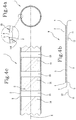
Figures 1a, 1b and 1c show, respectively, a transverse cross section, a product schematic and a longitudinal cross section of a first embodiment of a multilayer, cylindrical tubular rod; -
Figures 2a-2c ,3a-3c ,4a-4c and5a-5c show respective variants ofFigures 1a, 1b and 1c ; -
Figures 6a-6c show a further variant ofFigures 1a, 1b and 1c andFigure 6d shows a further product schematic; -
Figure 7 is a schematic front view of a machine for making pieces of a multilayer, cylindrical tubular rod a filter rod, according to a first embodiment; -
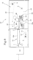
Figure 8 is a schematic front view of a machine for making pieces of a multilayer, cylindrical tubular rod according to a second embodiment; -
Figure 9 shows an enlarged detail fromFigure 7 ; -
Figure 10 is a side view of the detail ofFigure 9 ; -
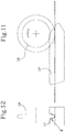
Figure 11 shows an enlarged detail fromFigure 7 representing the current invention; -
Figure 12 is a side view of the detail ofFigure 11 . - With reference to the accompanying drawings, the
numeral 1 denotes a multilayer, cylindrical tubular rod from which pieces suitable for making substantially cylindrical smokers' articles are obtained. - The
rod 1, and thus a piece of it not illustrated, comprises afirst layer 2 of a first material. Thefirst layer 2 is spliced longitudinally to form afirst splice 3 of respectivelateral edges 4 of thefirst layer 2. - The
rod 1, and thus a piece of it not illustrated, comprises asecond layer 5 of a second material. Thesecond layer 5 is spliced longitudinally to form asecond splice 6 of respectivelateral edges 7 of thesecond layer 5. - The
first layer 2 occupies a radially inner position relative to thesecond layer 5 in both the piece and therod 1. - The
second layer 5 is continuous along a main direction of extension "X" of therod 1, coinciding with the feed direction of the rod during production of the pieces. - At least one between the
first splice 3 and thesecond splice 6 is made as an end-to-end splice, that is, a splice made without overlapping the two respective lateral edges. - The first material and the second material are different. For example, the first material may be a metallic material and the second material may be a paper material.
-
Figures 1a and 1c illustrate arod 1 where thefirst layer 2 is also continuous along the main direction of extension "X" of therod 1. Further, both thefirst splice 3 and thesecond splice 6 are end-to-end splices and are offset from each other, that is, they are disposed at different angular positions around the direction "X".Figure 1b illustrates a step in the production of therod 1 from a continuous multilayer web "M" comprising thefirst layer 2 and thesecond layer 5, both laid out flat. Also illustrated is anintermediate layer 8 of adhesive material interposed between thefirst layer 2 and thesecond layer 5. -
Figures 2a and 2c illustrate arod 1 comprising athird layer 9 occupying a radially outer position relative to thefirst layer 2 andsecond layer 5. Thethird layer 9 is spliced longitudinally to form athird splice 10 of respectivelateral edges 4 of thethird layer 9. Both thefirst splice 3 and thesecond splice 6 are end-to-end splices and preferably are disposed at the same angular position around the direction "X". Thethird splice 10 is an end-to-end splice and is offset relative to the first and second splices, that is, disposed at a different angular position around the direction "X". - Again with reference to
Figures 2a and 2c , thefirst layer 2 is discontinuous and comprises, along the feed direction, a sequence ofstrips 14 alternated withempty spaces 15. In this case, complete closure of therod 1 is guaranteed by thethird layer 9 and thethird splice 10 offset from the other splices. -
Figure 2b illustrates a step in the production of therod 1 from a continuous multilayer web "M" comprising thefirst layer 2, thesecond layer 5 and thethird layer 9, all laid out flat. Also illustrated is theintermediate layer 8 of adhesive material interposed between thefirst layer 2 and thesecond layer 5 and a further intermediateadhesive layer 12 interposed between thesecond layer 5 and thethird layer 9. The third layer is offset along a direction perpendicular to the direction "X" relative to the first and second layers, so as to offset the respectivethird splice 10 relative to thefirst splice 3 andsecond splice 6. - The
second layer 5 and thethird layer 9 have the same thickness and are preferably obtained by dividing a single continuous web longitudinally, as described hereinafter. -
Figures 3a and 3c illustrate arod 1 comprising thethird layer 9 occupying a radially outer position relative to thefirst layer 2 andsecond layer 5. Thethird layer 9 is spliced longitudinally to form thethird splice 10 of respectivelateral edges 4 of thethird layer 9. Unlike the rod ofFigures 2a and 2c , thesecond layer 5 and thethird layer 9 have different thicknesses: in particular, thesecond layer 5 is smaller in thickness than thethird layer 9. In this case, the function of thesecond layer 5 is that of transporting thefirst layer 2. Thanks to the reduced thickness, it is easier to wrap it around itself and it may be made in such a way as to better absorb the adhesive material of theintermediate layer 8. Thethird layer 9 acts mainly as a supporting layer and gives therod 1 and the related pieces the stiffness necessary to keep their shape. - Again with reference to
Figures 3a and 3c , thefirst layer 2 is discontinuous and comprises, along the feed direction, the sequence ofstrips 14 alternated withempty spaces 15. In this case, complete closure of therod 1 is guaranteed by thethird layer 9 and thethird splice 10 offset from the other splices.Figure 3b is similar toFigure 2b . -
Figures 4a and 4c illustrate arod 1 comprising thethird layer 9 occupying a radially outer position relative to thefirst layer 2 andsecond layer 5. Thethird layer 9 is spliced longitudinally to form thethird splice 10 of respectivelateral edges 4 of thethird layer 9. Unlike the rod ofFigures 2a and 2c , thesecond layer 5 and thethird layer 9 have different thicknesses: in particular, thesecond layer 5 is larger in thickness than thethird layer 9. In this case, thesecond layer 5 acts both as a layer for transporting thefirst layer 2 and as a supporting layer giving therod 1 and the related pieces the stiffness necessary to keep their shape. The functions of thethird layer 9 are mainly to improve aesthetic appearance and to help keep thesecond layer 5 closed. - Again with reference to
Figures 4a and 4c , thefirst layer 2 is discontinuous and comprises, along the feed direction, the sequence ofstrips 14 alternated withempty spaces 15. In this case, complete closure of therod 1 is guaranteed by thethird layer 9 and thethird splice 10 offset from the other splices.Figure 4b is similar toFigure 2b . -
Figures 5a and 5c illustrate arod 1 comprising thethird layer 9 occupying a radially outer position relative to the first and second layers. Thethird layer 9 is spliced longitudinally to form thethird splice 10 of respectivelateral edges 4 of thethird layer 9. Unlike the rod ofFigures 2a and 2c , thethird splice 10 is an overlapping splice and is preferably offset from thefirst splice 3 or thesecond splice 6, that is, is disposed at a different angular position around the direction "X". - Again with reference to
Figures 5a and 5c , thefirst layer 2 is discontinuous and comprises, along the feed direction, a sequence ofstrips 14 alternated withempty spaces 15. In this case, the complete closure of therod 1 is guaranteed by thethird layer 9 and thethird splice 10 which is offset from the other splices and is an overlapping splice. -
Figure 5b illustrates a step in the production of therod 1 from a continuous multilayer web "M" comprising thefirst layer 2, thesecond layer 5 and thethird layer 9, all laid out flat. Also illustrated is theintermediate layer 8 of adhesive material interposed between thefirst layer 2 and thesecond layer 5 and the further intermediateadhesive layer 12 interposed between thesecond layer 5 and thethird layer 9. Thethird layer 9 is aligned at least at one of the lateral edges of thefirst layer 2 andsecond layer 5. -
Figures 6a and 6c illustrate arod 1 comprising thethird layer 9 occupying a radially outer position relative to the first and second layers. Thethird layer 9 is spliced longitudinally to form thethird splice 10 of respectivelateral edges 4 of thethird layer 9. Unlike the rod ofFigures 2a and 2c , thefirst splice 3 is an overlapping splice, thesecond splice 6 is an end-to-end splice and thethird splice 10 is an overlapping splice and is preferably offset from thefirst splice 3 or thesecond splice 6. Thesecond layer 5 and thethird layer 9 have different thicknesses: in particular, thesecond layer 5 is larger in thickness than thethird layer 9. - Again with reference to
Figures 6a and 6c , thefirst layer 2 is discontinuous and comprises, along the feed direction, a sequence ofstrips 14 alternated withempty spaces 15. In this case, complete closure of therod 1 is guaranteed by thethird layer 9 and thethird splice 10 offset from the other splices. The continuity of thefirst layer 2 along a circumferential direction is guaranteed by thefirst splice 3, which is an overlapping splice.Figure 6b illustrates a step in the production of therod 1 from a continuous multilayer web "M" comprising thefirst layer 2 and thesecond layer 5, which are laid out flat and which, when subsequently wrapped on themselves, form anintermediate rod 13. Also illustrated is theintermediate layer 8 of adhesive material interposed between thefirst layer 2 and thesecond layer 5.Figure 6d illustrates a further step in the production of therod 1 from theintermediate rod 13 and thethird layer 9. Thethird layer 9 will be wrapped around theintermediate rod 13 to form therod 1. Also shown is the further intermediateadhesive layer 12 interposed between thesecond layer 5 and thethird layer 9. - In all the examples illustrated and/or described above, the first material may comprise one or more of the following: a metallic material, a plastic material, a paper material.
-
Figures 7 and8 illustrate two possible embodiments of amachine 100 for making pieces of a multilayer, cylindricaltubular rod 1 suitable for making substantially cylindrical smokers' articles. More specifically, themachine 100 is adapted to make a piece of arod 1 according to one or more of the examples illustrated and/or described above. - The
machine 100 comprises first means 101 for feeding at least a firstcontinuous web 102 of a first material suitable for making thefirst layer 2 of a continuous, multilayer web "M" and of therod 1. - The
machine 100 comprises second means 103 for feeding a secondcontinuous web 104 of the second material suitable for making a secondcontinuous layer 5 of the continuous, multilayer web "M" and of therod 1. - The first
continuous web 102 and/or the secondcontinuous web 104 are preferably provided on rolls "B" unwound byrespective means - Located along the feed path of the second
continuous web 104 there is agluing device 105 configured to apply a layer of adhesive material on the secondcontinuous web 104 to define theintermediate layer 8 of adhesive material of therod 1. Theintermediate layer 8 is preferably continuous. Thegluing device 105 may be embodied, for example by rollers, sprayers or in other ways. - Located along the feed path of the first
continuous web 102 there may be acutting device 106 configured to cut the firstcontinuous web 102 intostrips 14. Thecutting device 106 is provided when thefirst layer 2 is discontinuous, that is to say, when it comprises a sequence ofstrips 14 alternated withempty spaces 15. Thecutting device 106 may be a cutter of the impact or scissor type or it may be embodied in other ways. - The numeral 107 denotes means for forming the continuous, multilayer web "M" by superposing at least the
first layer 2 and thesecond layer 5. These means may, for example, comprise abed 107a embodied by aconveyor 108 adapted to receive the secondcontinuous web 104 defining thesecond layer 5 and thestrips 14 of the firstcontinuous web 102 defining the first, discontinuous layer 2 (alternatively, the conveyor receives the firstcontinuous web 102 defining the first continuous layer 2). Theconveyor 108 is also adapted to feed the continuous, multilayer web "M" along the feed direction "X" and thus also embodies means for feeding the continuous, multilayer web "M" along the feed direction "X". Preferably, theconveyor 108 receives the secondcontinuous web 104 with theintermediate layer 8 which is applied thereon and on which thestrips 14 of the firstcontinuous web 102 are placed by adrum 109 associated with thecutting device 106. - Downstream of the
drum 109, therefore, the continuous, multilayer web "M" obtained is such that thefirst layer 2 in therod 1 occupies a radially inner position relative to thesecond layer 5. - Downstream of the
conveyor 108, means 110 are provided for forming therod 1 around the feed direction "X" making the splices of the layers making up the rod itself;
The means 110 may comprise a formingbeam 110a having a groove whose cross section is variable along the feed direction "X" in such a way as to wrap the continuous, multilayer web "M" around the feed direction "X" to make therod 1. - Downstream of the
means 110 for forming therod 1 there aremeans 111 for cutting therod 1 into pieces. - Advantageously, the
machine 100 is configured to dispose the lateral edges of at least one between thefirst layer 2 and thesecond layer 5 in such a way as to make at least one between thefirst splice 3 and thesecond splice 6 as an end-to-end splice. - As illustrated in
Figures 7 and8 , third means 112 may be provided for feeding a thirdcontinuous web 113 of a third material suitable for making thethird layer 9 of therod 1. The thirdcontinuous web 113, hence thethird layer 9, is disposed in such a way as to occupy, in therod 1, a radially outer position relative to thefirst layer 2 andsecond layer 5. Along the feed path of the thirdcontinuous web 113 there is agluing device 105a configured to apply the further intermediateadhesive layer 12 interposed between thesecond layer 5 and thethird layer 9. Thegluing device 105 may be embodied, for example by rollers, sprayers or in other ways. - In the example shown in
Figure 7 , the third means 112 feed thethird web 113 downstream of theconveyor 108 and upstream of themeans 110 to form thethird layer 9. Thus, thefirst layer 2, thesecond layer 5 and thethird layer 9 form the continuous, multilayer web "M" and are wrapped together on themselves along the formingbeam 110a. - If necessary, the
machine 100 may comprise twoblades 114 located on opposite sides of the continuous, multilayer web "M" and configured to trim the edges thereof. In the case ofFigure 7 , theblades 114 are circular blades which use as their anvil element aflat surface 115 on which at least one active portion of theconveyor 108 slides. The blades are located downstream of thedrum 109 and thus trim the continuous, multilayer web "M" comprising thefirst layer 2 and thesecond layer 5. - According with the invention, the
machine 100 comprises a formingdevice 116 configured to preform the continuous, multilayer web "M" before it is wrapped on itself to form therod 1.Figures 11 and 12 illustrate a possible example of the formingdevice 116, which can be used in any machine for forming arod 1 and which comprises a mouldedgroove 117, adapted to receive the continuous, multilayer web "M", and a forming element - for example awheel 118 preferably rotating about a horizontal axis perpendicular to the feed direction "X" - which fits at least partly in the mouldedgroove 117 to make in the continuous, multilayer web a grooved shape extending along the middle of it in the feed direction "X". The formingdevice 116 may act on a continuous, multilayer web "M" comprising only thefirst layer 2 and thesecond layer 5 or, as illustrated inFigure 7 , on a continuous, multilayer web "M" comprising thefirst layer 2, thesecond layer 5 and thethird layer 9. - As can be seen in
figure 12 , thewheel 118 has a central disc-shaped portion having a tapered periphery ending in a rounded rim which, in transverse section, has the shape of an arc of circumference, in particular about half of a circumference. - Preferably, between the tapered periphery and the rounded rim of the
wheel 118 an annular portion is provided, with has parallel flanks perpendicular to the axis of rotation of thewheel 118. - Moreover, as can be seen in
figure 12 , the mouldedgroove 117 and thewheel 118 have a transversal outline that causes thewheel 118 to enter in contact with the continuous, multilayer web "M" only at the rounded rim of thewheel 118. - As can be seen in
figure 11 , the forming element (wheel 118) is located at the infeed portion of the mouldedgroove 117 along the feed direction "X". - The
machine 100 illustrated inFigure 8 differs from the machine illustrated inFigure 7 in that it comprises two forming beams. The first formingbeam 110a is similar to the one illustrated inFigure 7 and is configured to make therod 1. A further formingbeam 119 is located at theconveyor 108 to wrap the continuous, multilayer web "M", comprising thefirst layer 2 and thesecond layer 5, on itself to form theintermediate rod 13. The thirdcontinuous web 113 is fed between the further formingbeam 119 and the formingbeam 110a to wrap the thirdcontinuous web 113 around theintermediate rod 13 to form therod 1. - In use, the
machine 100 is adapted to function according to a method for making pieces of a multilayer, cylindrical tubular rod suitable for making substantially cylindrical smokers' articles. - The above mentioned method comprises a step a) of feeding at least a first
continuous web 102 of a first material suitable for making afirst layer 2 of a continuous, multilayer web "M". This step is carried out, for example, by the first feed means 101. - The above mentioned method comprises a step b) of feeding a second
continuous web 104 of a second material suitable for making a secondcontinuous layer 5 of the continuous, multilayer web "M". This step is carried out, for example, by the second feed means 103. - Preferably, there is a step f) of feeding a third
continuous web 113 of a third material suitable for making athird layer 9 of therod 1. Thethird layer 9 is disposed in such a way as to occupy, in therod 1, a radially outer position relative to thefirst layer 2 andsecond layer 5. - The above mentioned method comprises a step c) of forming the continuous, multilayer web "M" by superposing at least the
first layer 2 and thesecond layer 5, where thefirst layer 2 is positioned in such a way as to occupy, in therod 1, a radially inner position relative to thesecond layer 5, and feeding the continuous, multilayer web "M" along a feed direction "X". This step is carried out, for example, at themeans 107 and at theconveyor 108. - The above mentioned method comprises a step d) of wrapping the continuous, multilayer web "M" around the feed direction "X", making at least a
first splice 3 of the lateral edges of thefirst layer 2 and asecond splice 6 of the lateral edges of thesecond layer 5, to form therod 1. This step may be carried out in the formingbeam 110a to form a continuous, multilayer web "M" comprising thefirst layer 2, thesecond layer 5 and possibly also thethird layer 9, or in the formingbeam 119 to form a continuous, multilayer web "M" comprising thefirst layer 2 and thesecond layer 5. In the latter case, the forming of therod 1 may, if necessary, be completed by wrapping thethird layer 9 around theintermediate rod 13. The above mentioned method comprises a step e) of cutting therod 1 into pieces. - Steps a) to e) are carried out in a
single machine 100 to make a multilayer, cylindricaltubular rod 1. Also, step d) is carried out by disposing the lateral edges of at least one between thefirst layer 2 and thesecond layer 5 in such a way as to make at least one between thefirst splice 3 and thesecond splice 6 as an end-to-end splice. - Preferably, there is a step of making
strips 14 of the firstcontinuous web 102 and making a first,discontinuous layer 2 along the feed direction "X" where the first,layer 2 comprises, along the feed direction, a sequence ofstrips 14 alternated withempty spaces 15. This step is carried out, for example, by thecutting device 106. - If necessary, there may be a step of feeding a single continuous web suitable for making the
second layer 5 and thethird layer 9 and a step of dividing the single continuous web longitudinally into two continuous web portions respectively defining the secondcontinuous web 104 and the thirdcontinuous web 113. In this case, the secondcontinuous web 104 and the thirdcontinuous web 113 have the same thickness. Alternatively, the secondcontinuous web 104 and the thirdcontinuous web 113 have different thicknesses. - As illustrated in
Figure 7 , step c) comprises first forming the continuous, multilayer web "M" by superposing thefirst layer 2 and thesecond layer 5 and then adding thethird layer 9. The continuous, multilayer web "M" thus obtained (that is to say, comprising thefirst layer 2, thesecond layer 5 and the third layer 9) is wrapped on itself around the feed direction "X" to form therod 1. - In a possible embodiment, step d) may be carried out by disposing the lateral edges of the
first layer 2 in such a way as to make a first end-to-end splice 3 and disposing the lateral edges of thesecond layer 5 in such a way as to make a second end-to-end splice 6. - In this case, step c) might comprise the step of offsetting the
third layer 9 relative to at least one between the first and the second layer along a direction perpendicular to the feed direction "X" and step d) might be carried out by disposing the lateral edges of the third layer in such a way as to make a third end-to-end splice 10 (Figures 2a-4a ). Alternatively, step d) might be carried out by disposing the lateral edges of thethird layer 9 in such a way as to make the third splice an overlapping splice (Figure 5a ). As illustrated inFigure 8 , step c) comprises forming the continuous, multilayer web "M" by superposing thefirst layer 2 and thesecond layer 5. Next, the continuous, multilayer web "M" is wrapped on itself to form anintermediate rod 13 and juxtaposed with the thirdcontinuous web 113, that is, with thethird layer 9, to wrap the thirdcontinuous web 113 around theintermediate rod 13 to form therod 1. In other words., there is a step g) of wrapping thethird layer 9 around theintermediate rod 13 already formed by wrapping the first and second layers around themselves. Preferably, step d) may be carried out by disposing thelateral edges 4 of thefirst layer 2 in such a way as to make at least a first, overlappingsplice 3 and disposing thelateral edges 7 of thesecond layer 5 in such a way as to make a second, end-to-end splice 6. Preferably, step g) is carried out by disposing the lateral edges 11 of thethird layer 9 in such a way as to make a third, overlapping splice 10 (Figure 6a ). - If necessary, the edges of the continuous, multilayer web "M" might be trimmed before the web is wrapped on itself to form a multilayer, cylindrical tubular rod. More specifically, the edges of the continuous, multilayer web "M" formed by the
first layer 2 andsecond layer 5 might be trimmed in an embodiment where there is athird layer 9. - Advantageously, before the continuous, multilayer web "M" is wrapped on itself to form the
rod 1, it is preformed by making in the continuous, multilayer web "M" a grooved shaping extending along the feed direction "X". - In an alternative not illustrated, the
machine 100 is adapted to makerods 1 which comprise only thefirst layer 2 and thesecond layer 5 with a first and a second end-to-end splice. In this case, thefirst layer 2 is continuous along the feed direction "X" and thefirst layer 2 andsecond layer 5 are offset in a direction perpendicular to the feed direction "X". - Even independently of what is described in the foregoing, the method according to this invention may involve a
second layer 2 and athird layer 9 having the same thickness or different thicknesses. In the first case, there may be a step of feeding a single continuous web suitable for making the second and third layers and a step of dividing the single continuous web longitudinally into two continuous web portions respectively defining the secondcontinuous web 104 and the thirdcontinuous web 113.
Claims (16)
- A method for making pieces of a multilayer, cylindrical tubular rod (1) suitable for making substantially cylindrical smokers' articles, comprising the steps of:a) feeding at least a first continuous web (102) of a first material suitable for making a first layer (2) of a continuous, multilayer web (M);b) feeding a second continuous web (104) of a second material suitable for making a second continuous layer (5) of the continuous, multilayer web (M);c) forming the continuous, multilayer web (M) by superposing at least the first layer (2) and the second layer (5) with an intermediate layer (8) of adhesive material interposed between the first layer (2) and the second layer (5), wherein the first layer (2) is positioned in such a way as to occupy, in the rod (1), a radially inner position relative to the second layer (5), and feeding the continuous, multilayer web (M) along a feed direction (X);d) wrapping the continuous, multilayer web (M) around the feed direction (X), making at least a first splice (3) of the lateral edges (4) of the first layer (2) and a second splice (6) of the lateral edges (7) of the second layer (5), to obtain a rod (1);e) cutting the rod (1) into pieces;
characterized in that it comprises preforming the continuous, multilayer web (M), before wrapping it and forming a multilayer, cylindrical tubular rod (1), preferably producing a central shaping extending along the middle of the continuous, multilayer web in the feed direction (X). - The method for making pieces of a multilayer, cylindrical tubular rod according to claim 1, wherein the step of preforming the continuous, multilayer web (M), is performed by a moulded groove (117) into which the continuous, multilayer web (M) is received and by a forming element which fits at least partly in the moulded groove (117) to make said grooved shaping in the continuous, multilayer web (M).
- The method for making pieces of a multilayer, cylindrical tubular rod according to claim 2, wherein the forming element is a wheel (118) in particular rotating about a horizontal axis perpendicular to the feed direction (X).
- The method for making pieces of a multilayer, cylindrical tubular rod according to claim 3, wherein the wheel (118) has a central disc-shaped portion having a tapered periphery ending in a rounded rim which, in transverse section, has the shape of an arc of circumference, in particular about half of a circumference; preferably, between the tapered periphery and the rounded rim being provided an annular portion with parallel flanks perpendicular to the axis of rotation of the wheel (118).
- The method for making pieces of a multilayer, cylindrical tubular rod according to claim 4, wherein the moulded groove (117) and the wheel (118) have a transversal outline that causes the wheel (118) to enter in contact with the continuous, multilayer web (M) only at the rounded rim of the wheel (118).
- The method for making pieces of a multilayer, cylindrical tubular rod according to any of the preceding claims from 2 to 5, wherein the forming element is located at an infeed portion of the moulded groove (117) along the feed direction (X).
- The method for making pieces of a multilayer, cylindrical tubular rod according to any of the preceding claims, wherein it comprises a step f) of feeding a third continuous web (113) of a third material suitable for making a third layer (9) of the rod (1), wherein the third layer (9) is added on the superposed first and second layers (2, 5) by interposing a further intermediate adhesive layer (12) between the second layer and the third layer (5, 9), and wherein the third layer (9) is positioned in such a way as to occupy, in the rod (1), a radially outer position relative to the first and second layers (2, 5).
- The method for making pieces of a multilayer, cylindrical tubular rod according to any of the preceding claims, wherein steps a)-e) are performed on a single machine (100) for making a multilayer, cylindrical tubular rod (1) wherein the step d) is accomplished by disposing the lateral edges (4, 7) of at least one between the first and the second layer (2, 5) in such a way as to make at least one between the first and the second splice (3, 6) as an end-to-end splice.
- A machine (100) for making pieces of a multilayer, cylindrical tubular rod suitable for making substantially cylindrical smokers' articles, characterized in that it comprises:first means (101) for feeding at least a first continuous web (102) of a first material suitable for making a first layer (2) of a continuous, multilayer web (M);second means (103) for feeding a second continuous web (104) of a second material suitable for making a second continuous layer (5) of the continuous, multilayer web (M);means (107) for forming the continuous, multilayer web (M) by superposing at least the first layer (2) and the second layer (5), wherein the first layer (2) is positioned in such a way as to occupy, in the rod (1), a radially inner position relative to the second layer (5), and means (108) for feeding the continuous, multilayer web along a feed direction (X);a gluing device (105) configured to release an intermediate layer (8) of adhesive material between the first and second layer (2, 5), in particular configured to apply a layer of adhesive material on the second continuous web (104); means (110) for forming the rod (1) around the feed direction (X) making the splices (3, 6, 10) of the layers making up the rod itself;means (111) for cutting the rod (1) into pieces;a forming device (116) configured to preform the continuous, multilayer web (M) before it is wrapped to form the rod (1), preferably producing a central shaping extending along the middle of the continuous, multilayer web in the feed direction (X).
- The machine for making pieces of a multilayer, cylindrical tubular rod according to claim 9, wherein the forming device (116) comprises a moulded groove (117) into which the continuous, multilayer web (M) is received and a forming element which fits at least partly in the moulded groove (117) to make said grooved shaping in the continuous, multilayer web (M).
- The machine for making pieces of a multilayer, cylindrical tubular rod according to claim 10, wherein the forming element is a wheel (118) in particular rotating about a horizontal axis perpendicular to the feed direction (X).
- The machine for making pieces of a multilayer, cylindrical tubular rod according to claim 11, wherein the wheel (118) has a central disc-shaped portion having a tapered periphery ending in a rounded rim which, in transverse section, has the shape of an arc of circumference, in particular about half of a circumference; preferably, between the tapered periphery and the rounded rim being provided an annular portion with parallel flanks perpendicular to the axis of rotation of the wheel (118).
- The machine for making pieces of a multilayer, cylindrical tubular rod according to claim 12, wherein the moulded groove (117) and the wheel (118) have a transversal outline that causes the wheel to enter in contact with the continuous, multilayer web (M) only at the rounded rim of the wheel.
- The machine for making pieces of a multilayer, cylindrical tubular rod according to any of the preceding claims from 10 to 13, wherein the forming element is located at an infeed portion of the moulded groove (117) along the feed direction (X).
- The machine (100) for making pieces of a multilayer, cylindrical tubular rod according to any of preceding claims 9 to 14, further comprising third means (112) for feeding a third continuous web (113) of a third material suitable for making a third layer (9) of the rod (1) and a further gluing device (105a) configured to apply a further intermediate adhesive layer (12) interposed between the second layer (5) and the third layer (9), in particular located along a feed path of the third continuous web (113), wherein the third layer (9) is positioned in such a way as to occupy, in the rod (1), a radially outer position relative to the first and second layers (2, 5).
- The machine (100) for making pieces of a multilayer, cylindrical tubular rod according to any of preceding claims 9 to 15, wherein the machine (100) is configured to dispose the lateral edges (4, 7) of at least one between the first and the second layer (2, 5) in such a way as to make at least one between the first and the second splice (3, 6) as an end-to-end splice.
Applications Claiming Priority (3)
| Application Number | Priority Date | Filing Date | Title |
|---|---|---|---|
| ITUB2016A000048A ITUB20160048A1 (en) | 2016-01-26 | 2016-01-26 | Method and machine for the production of sections of a multilayer tubular cylindrical silkworm suitable for the production of substantially cylindrical smoking articles and relative lengths. |
| EP17706305.4A EP3407742B1 (en) | 2016-01-26 | 2017-01-24 | Method and machine for making pieces of a multilayer, cylindrical tubular rod used to make substantially cylindrical smokers' articles, and the pieces made by the method and machine |
| PCT/IB2017/050354 WO2017130098A1 (en) | 2016-01-26 | 2017-01-24 | Method and machine for making pieces of a multilayer, cylindrical tubular rod used to make substantially cylindrical smokers' articles, and the pieces made by the method and machine |
Related Parent Applications (2)
| Application Number | Title | Priority Date | Filing Date |
|---|---|---|---|
| EP17706305.4A Division EP3407742B1 (en) | 2016-01-26 | 2017-01-24 | Method and machine for making pieces of a multilayer, cylindrical tubular rod used to make substantially cylindrical smokers' articles, and the pieces made by the method and machine |
| EP17706305.4A Division-Into EP3407742B1 (en) | 2016-01-26 | 2017-01-24 | Method and machine for making pieces of a multilayer, cylindrical tubular rod used to make substantially cylindrical smokers' articles, and the pieces made by the method and machine |
Publications (1)
| Publication Number | Publication Date |
|---|---|
| EP3821721A1 true EP3821721A1 (en) | 2021-05-19 |
Family
ID=55860912
Family Applications (2)
| Application Number | Title | Priority Date | Filing Date |
|---|---|---|---|
| EP17706305.4A Active EP3407742B1 (en) | 2016-01-26 | 2017-01-24 | Method and machine for making pieces of a multilayer, cylindrical tubular rod used to make substantially cylindrical smokers' articles, and the pieces made by the method and machine |
| EP20207451.4A Pending EP3821721A1 (en) | 2016-01-26 | 2017-01-24 | Method and machine for making pieces of a multilayer, cylindrical tubular rod used to make substantially cylindrical smokers articles |
Family Applications Before (1)
| Application Number | Title | Priority Date | Filing Date |
|---|---|---|---|
| EP17706305.4A Active EP3407742B1 (en) | 2016-01-26 | 2017-01-24 | Method and machine for making pieces of a multilayer, cylindrical tubular rod used to make substantially cylindrical smokers' articles, and the pieces made by the method and machine |
Country Status (8)
| Country | Link |
|---|---|
| EP (2) | EP3407742B1 (en) |
| JP (2) | JP7118897B2 (en) |
| KR (1) | KR102760022B1 (en) |
| CN (1) | CN108601391B (en) |
| IT (1) | ITUB20160048A1 (en) |
| PL (1) | PL3407742T3 (en) |
| RU (1) | RU2736437C2 (en) |
| WO (1) | WO2017130098A1 (en) |
Families Citing this family (6)
| Publication number | Priority date | Publication date | Assignee | Title |
|---|---|---|---|---|
| DE102017114910A1 (en) * | 2017-07-04 | 2019-01-10 | Hauni Maschinenbau Gmbh | Method for producing hollow tubes of the tobacco processing industry and format device |
| DE102018121548A1 (en) * | 2018-09-04 | 2020-03-05 | Hauni Maschinenbau Gmbh | Hollow tube production in the tobacco processing industry |
| IT201800009354A1 (en) * | 2018-10-11 | 2020-04-11 | Gd Spa | PROCEDURE AND MACHINE FOR MAKING MULTILAYER TUBULARS FOR THE TOBACCO INDUSTRY |
| DE102020107088A1 (en) | 2020-03-16 | 2021-09-16 | Hauni Maschinenbau Gmbh | Device for the production of hollow pipes, in particular drinking straws, and method therefor |
| IT202100013010A1 (en) | 2021-05-20 | 2022-11-20 | Gd Spa | Machine and method for making tubular pieces, in particular from the tobacco industry or the straw industry |
| WO2023188223A1 (en) * | 2022-03-31 | 2023-10-05 | 日本たばこ産業株式会社 | Cylindrical body |
Citations (5)
| Publication number | Priority date | Publication date | Assignee | Title |
|---|---|---|---|---|
| DE1657260A1 (en) * | 1967-02-21 | 1971-02-11 | Molins Machine Co Ltd | Method and device for manufacturing a tube from strip material, e.g. a mouthpiece tube for cigarettes |
| GB2014427A (en) * | 1978-02-10 | 1979-08-30 | Burrus & Cie | Cigarette sleeve with filter |
| GB2171168A (en) * | 1985-02-16 | 1986-08-20 | Molins Plc | Fluid mandrel |
| WO2014068703A1 (en) * | 2012-10-31 | 2014-05-08 | 日本たばこ産業株式会社 | Paper tube manufacturing machine, manufacturing method for same, and paper tube manufactured by said manufacturing method |
| WO2014188318A1 (en) | 2013-05-22 | 2014-11-27 | G. D S.P.A. | Apparatus for making smokers' articles |
Family Cites Families (15)
| Publication number | Priority date | Publication date | Assignee | Title |
|---|---|---|---|---|
| GB453172A (en) * | 1935-04-05 | 1936-09-07 | Walter Everett Molins | Improvements in or relating to the manufacture of paper and like tubes |
| GB661626A (en) * | 1949-06-22 | 1951-11-21 | Hugo Bunzl | Improvements in and relating to filter plugs for cigarettes |
| DE1105328B (en) * | 1958-07-04 | 1961-04-20 | Hauni Werke Koerber & Co Kg | Method and device for the production of recess filters, -filterstaeben or the like. |
| BE756514A (en) * | 1969-10-06 | 1971-03-01 | Kastner Arnold | MACHINE FOR MANUFACTURING TUBES FOR CIGARETTES |
| GB1311437A (en) * | 1971-03-10 | 1973-03-28 | British American Tobacco Co | Production of tubes |
| GB1400421A (en) * | 1971-08-13 | 1975-07-16 | Hauni Werke Koerber & Co Kg | Mouthpiece tubes or sleeves for cigarettes or the like |
| GB8504021D0 (en) * | 1985-02-16 | 1985-03-20 | Molins Plc | Tube manufacture |
| FR2898122B1 (en) * | 2006-03-06 | 2008-12-05 | Saint Gobain | SUBSTRATE PROVIDED WITH A STACK WITH THERMAL PROPERTIES |
| US8142598B2 (en) * | 2007-12-28 | 2012-03-27 | Philip Morris Usa Inc. | Filter tube making |
| GB0809135D0 (en) * | 2008-05-20 | 2008-06-25 | British American Tobacco Co | Apparatus and method for making a smoking article |
| JP5894563B2 (en) | 2013-07-26 | 2016-03-30 | 株式会社ブリヂストン | Roller for applying rubber adhesive |
| DE102014213858B3 (en) * | 2014-07-16 | 2015-11-12 | Hauni Maschinenbau Ag | Apparatus for applying a glue trace to a wrapping strip of a rod-shaped product of the tobacco processing industry |
| GB2537349A (en) | 2015-03-31 | 2016-10-19 | British American Tobacco Investments Ltd | Apparatus and method for applying adhesive to a wrapper for a smoking article |
| KR102014427B1 (en) * | 2015-07-07 | 2019-08-26 | 엘에스산전 주식회사 | Power network mom|nitering system and method thereof |
| KR102171168B1 (en) * | 2018-09-11 | 2020-10-28 | 주식회사 포스코 | Level measuring apparatus and method for cokes oven |
-
2016
- 2016-01-26 IT ITUB2016A000048A patent/ITUB20160048A1/en unknown
-
2017
- 2017-01-24 JP JP2018557227A patent/JP7118897B2/en active Active
- 2017-01-24 EP EP17706305.4A patent/EP3407742B1/en active Active
- 2017-01-24 CN CN201780007711.3A patent/CN108601391B/en active Active
- 2017-01-24 WO PCT/IB2017/050354 patent/WO2017130098A1/en not_active Ceased
- 2017-01-24 KR KR1020187021662A patent/KR102760022B1/en active Active
- 2017-01-24 RU RU2018125652A patent/RU2736437C2/en active
- 2017-01-24 PL PL17706305.4T patent/PL3407742T3/en unknown
- 2017-01-24 EP EP20207451.4A patent/EP3821721A1/en active Pending
-
2022
- 2022-05-25 JP JP2022084983A patent/JP2022116159A/en active Pending
Patent Citations (5)
| Publication number | Priority date | Publication date | Assignee | Title |
|---|---|---|---|---|
| DE1657260A1 (en) * | 1967-02-21 | 1971-02-11 | Molins Machine Co Ltd | Method and device for manufacturing a tube from strip material, e.g. a mouthpiece tube for cigarettes |
| GB2014427A (en) * | 1978-02-10 | 1979-08-30 | Burrus & Cie | Cigarette sleeve with filter |
| GB2171168A (en) * | 1985-02-16 | 1986-08-20 | Molins Plc | Fluid mandrel |
| WO2014068703A1 (en) * | 2012-10-31 | 2014-05-08 | 日本たばこ産業株式会社 | Paper tube manufacturing machine, manufacturing method for same, and paper tube manufactured by said manufacturing method |
| WO2014188318A1 (en) | 2013-05-22 | 2014-11-27 | G. D S.P.A. | Apparatus for making smokers' articles |
Also Published As
| Publication number | Publication date |
|---|---|
| ITUB20160048A1 (en) | 2017-07-26 |
| KR102760022B1 (en) | 2025-01-24 |
| RU2018125652A (en) | 2020-02-28 |
| WO2017130098A1 (en) | 2017-08-03 |
| JP7118897B2 (en) | 2022-08-16 |
| CN108601391B (en) | 2021-11-12 |
| RU2736437C2 (en) | 2020-11-17 |
| KR20180108624A (en) | 2018-10-04 |
| EP3407742B1 (en) | 2025-06-04 |
| CN108601391A (en) | 2018-09-28 |
| PL3407742T3 (en) | 2025-09-08 |
| EP3407742A1 (en) | 2018-12-05 |
| JP2019509056A (en) | 2019-04-04 |
| JP2022116159A (en) | 2022-08-09 |
| RU2018125652A3 (en) | 2020-04-30 |
Similar Documents
| Publication | Publication Date | Title |
|---|---|---|
| EP3407742B1 (en) | Method and machine for making pieces of a multilayer, cylindrical tubular rod used to make substantially cylindrical smokers' articles, and the pieces made by the method and machine | |
| KR102569141B1 (en) | Double-layered tube of the tobacco processing industry and method for producing such a tube | |
| US10111459B2 (en) | Assembly machine for producing cigarettes, and relative assembly method | |
| CA2057392C (en) | Paint roller and method and apparatus of manufacturing a paint roller | |
| RU2560834C2 (en) | Smoking product wrapper | |
| CA2921194A1 (en) | Method and apparatus for manufacturing variable crimped web material | |
| JP7136574B2 (en) | Method for producing an at least two-layer tube-shaped continuous body for the tobacco processing industry and apparatus for producing an at least two-layer tube-shaped continuous body for the tobacco processing industry | |
| KR20220146435A (en) | Method and machine for manufacturing continuous tubular elements with fillers having spacer and/or filter functions | |
| ITBO20110331A1 (en) | METHOD AND FILTER MACHINE TO MAKE CIGARETTES WITH FILTER. | |
| EP2999360B1 (en) | Apparatus for making smokers' articles | |
| EP3784066B1 (en) | Multilayer tube of the tobacco industry and method for making the multilayer tube | |
| US20090208745A1 (en) | Composite material placement | |
| EP3636082A2 (en) | Multilayer tube and related machine and method for making it | |
| EP2999362B1 (en) | Apparatus for making smokers' articles | |
| KR101448196B1 (en) | Tubular shape felt filter manufacturing equipment | |
| EP3429379B1 (en) | Device for making smokers' articles | |
| WO2015001316A1 (en) | Curling machine | |
| JP2011245874A (en) | Apparatus and method for manufacturing of object closed onto itself |
Legal Events
| Date | Code | Title | Description |
|---|---|---|---|
| PUAI | Public reference made under article 153(3) epc to a published international application that has entered the european phase |
Free format text: ORIGINAL CODE: 0009012 |
|
| STAA | Information on the status of an ep patent application or granted ep patent |
Free format text: STATUS: THE APPLICATION HAS BEEN PUBLISHED |
|
| AC | Divisional application: reference to earlier application |
Ref document number: 3407742 Country of ref document: EP Kind code of ref document: P |
|
| AK | Designated contracting states |
Kind code of ref document: A1 Designated state(s): AL AT BE BG CH CY CZ DE DK EE ES FI FR GB GR HR HU IE IS IT LI LT LU LV MC MK MT NL NO PL PT RO RS SE SI SK SM TR |
|
| STAA | Information on the status of an ep patent application or granted ep patent |
Free format text: STATUS: REQUEST FOR EXAMINATION WAS MADE |
|
| 17P | Request for examination filed |
Effective date: 20211118 |
|
| RBV | Designated contracting states (corrected) |
Designated state(s): AL AT BE BG CH CY CZ DE DK EE ES FI FR GB GR HR HU IE IS IT LI LT LU LV MC MK MT NL NO PL PT RO RS SE SI SK SM TR |
|
| P01 | Opt-out of the competence of the unified patent court (upc) registered |
Effective date: 20230526 |
|
| STAA | Information on the status of an ep patent application or granted ep patent |
Free format text: STATUS: EXAMINATION IS IN PROGRESS |
|
| 17Q | First examination report despatched |
Effective date: 20231208 |
|
| GRAP | Despatch of communication of intention to grant a patent |
Free format text: ORIGINAL CODE: EPIDOSNIGR1 |
|
| STAA | Information on the status of an ep patent application or granted ep patent |
Free format text: STATUS: GRANT OF PATENT IS INTENDED |
|
| INTG | Intention to grant announced |
Effective date: 20260703 |