EP3821615B1 - Identification of cushioning members in personal audio devices - Google Patents
Identification of cushioning members in personal audio devices Download PDFInfo
- Publication number
- EP3821615B1 EP3821615B1 EP20771960.0A EP20771960A EP3821615B1 EP 3821615 B1 EP3821615 B1 EP 3821615B1 EP 20771960 A EP20771960 A EP 20771960A EP 3821615 B1 EP3821615 B1 EP 3821615B1
- Authority
- EP
- European Patent Office
- Prior art keywords
- earpiece
- cushioning member
- tag
- identification data
- identification
- Prior art date
- Legal status (The legal status is an assumption and is not a legal conclusion. Google has not performed a legal analysis and makes no representation as to the accuracy of the status listed.)
- Active
Links
Images












Classifications
-
- H—ELECTRICITY
- H04—ELECTRIC COMMUNICATION TECHNIQUE
- H04R—LOUDSPEAKERS, MICROPHONES, GRAMOPHONE PICK-UPS OR LIKE ACOUSTIC ELECTROMECHANICAL TRANSDUCERS; ELECTRIC HEARING AIDS; PUBLIC ADDRESS SYSTEMS
- H04R1/00—Details of transducers, loudspeakers or microphones
- H04R1/10—Earpieces; Attachments therefor ; Earphones; Monophonic headphones
- H04R1/1041—Mechanical or electronic switches, or control elements
-
- H—ELECTRICITY
- H04—ELECTRIC COMMUNICATION TECHNIQUE
- H04B—TRANSMISSION
- H04B5/00—Near-field transmission systems, e.g. inductive or capacitive transmission systems
- H04B5/70—Near-field transmission systems, e.g. inductive or capacitive transmission systems specially adapted for specific purposes
- H04B5/77—Near-field transmission systems, e.g. inductive or capacitive transmission systems specially adapted for specific purposes for interrogation
-
- H—ELECTRICITY
- H04—ELECTRIC COMMUNICATION TECHNIQUE
- H04R—LOUDSPEAKERS, MICROPHONES, GRAMOPHONE PICK-UPS OR LIKE ACOUSTIC ELECTROMECHANICAL TRANSDUCERS; ELECTRIC HEARING AIDS; PUBLIC ADDRESS SYSTEMS
- H04R1/00—Details of transducers, loudspeakers or microphones
- H04R1/10—Earpieces; Attachments therefor ; Earphones; Monophonic headphones
- H04R1/1016—Earpieces of the intra-aural type
-
- H—ELECTRICITY
- H04—ELECTRIC COMMUNICATION TECHNIQUE
- H04R—LOUDSPEAKERS, MICROPHONES, GRAMOPHONE PICK-UPS OR LIKE ACOUSTIC ELECTROMECHANICAL TRANSDUCERS; ELECTRIC HEARING AIDS; PUBLIC ADDRESS SYSTEMS
- H04R25/00—Electric hearing aids
- H04R25/65—Housing parts, e.g. shells, tips or moulds, or their manufacture
- H04R25/652—Ear tips; Ear moulds
-
- H—ELECTRICITY
- H04—ELECTRIC COMMUNICATION TECHNIQUE
- H04B—TRANSMISSION
- H04B5/00—Near-field transmission systems, e.g. inductive or capacitive transmission systems
- H04B5/20—Near-field transmission systems, e.g. inductive or capacitive transmission systems characterised by the transmission technique; characterised by the transmission medium
- H04B5/24—Inductive coupling
- H04B5/26—Inductive coupling using coils
- H04B5/266—One coil at each side, e.g. with primary and secondary coils
-
- H—ELECTRICITY
- H04—ELECTRIC COMMUNICATION TECHNIQUE
- H04R—LOUDSPEAKERS, MICROPHONES, GRAMOPHONE PICK-UPS OR LIKE ACOUSTIC ELECTROMECHANICAL TRANSDUCERS; ELECTRIC HEARING AIDS; PUBLIC ADDRESS SYSTEMS
- H04R1/00—Details of transducers, loudspeakers or microphones
- H04R1/10—Earpieces; Attachments therefor ; Earphones; Monophonic headphones
- H04R1/1008—Earpieces of the supra-aural or circum-aural type
-
- H—ELECTRICITY
- H04—ELECTRIC COMMUNICATION TECHNIQUE
- H04R—LOUDSPEAKERS, MICROPHONES, GRAMOPHONE PICK-UPS OR LIKE ACOUSTIC ELECTROMECHANICAL TRANSDUCERS; ELECTRIC HEARING AIDS; PUBLIC ADDRESS SYSTEMS
- H04R2420/00—Details of connection covered by H04R, not provided for in its groups
- H04R2420/07—Applications of wireless loudspeakers or wireless microphones
-
- H—ELECTRICITY
- H04—ELECTRIC COMMUNICATION TECHNIQUE
- H04R—LOUDSPEAKERS, MICROPHONES, GRAMOPHONE PICK-UPS OR LIKE ACOUSTIC ELECTROMECHANICAL TRANSDUCERS; ELECTRIC HEARING AIDS; PUBLIC ADDRESS SYSTEMS
- H04R2460/00—Details of hearing devices, i.e. of ear- or headphones covered by H04R1/10 or H04R5/033 but not provided for in any of their subgroups, or of hearing aids covered by H04R25/00 but not provided for in any of its subgroups
- H04R2460/01—Hearing devices using active noise cancellation
-
- H—ELECTRICITY
- H04—ELECTRIC COMMUNICATION TECHNIQUE
- H04R—LOUDSPEAKERS, MICROPHONES, GRAMOPHONE PICK-UPS OR LIKE ACOUSTIC ELECTROMECHANICAL TRANSDUCERS; ELECTRIC HEARING AIDS; PUBLIC ADDRESS SYSTEMS
- H04R2460/00—Details of hearing devices, i.e. of ear- or headphones covered by H04R1/10 or H04R5/033 but not provided for in any of their subgroups, or of hearing aids covered by H04R25/00 but not provided for in any of its subgroups
- H04R2460/15—Determination of the acoustic seal of ear moulds or ear tips of hearing devices
Definitions
- This disclosure relates generally to personal audio devices such as earbuds and headphones and in particular to identification of removable cushioning members such as ear tips and cushions by a personal audio device that can support adaptive behavior based on the presence of a particular cushioning member.
- a "personal audio device” refers to a device that produces sound to be heard by an individual user while limiting the audibility of that sound in an environment around the user.
- Examples of personal audio devices include headphones and earphones.
- Headphones generally include one or two audio-producing earpieces (also referred to as "ear cups") that are designed to be worn over the ear or on the ear.
- the ear cups are typically connected to a headband, which can help to hold the ear cups in place and can also provide an electrical connection between the ear cups.
- the ear cups are designed to be worn such that an audio-generating speaker contained in each ear cup directs sound toward an ear of the wearer.
- a cushion made of compliant material is typically provided around a peripheral portion of the ear cup in order to provide spacing between the speaker and the user's ear and to provide user comfort while wearing the headphones.
- the cushion may also provide sound insulation, preventing sound generated by the ear cups from leaking into the environment and/or preventing external sound from reaching the user's ears.
- Earphones generally include one or two audio-producing earpieces (also referred to as "earbuds”) that are designed to be inserted into the user's ears (either into the ear canal or resting against the concha cavum) such that an audio-generating speaker contained in the earpiece (or earbud) is oriented toward the ear canal.
- An ear tip (also sometimes referred to herein as a "tip”) made of soft material may be provided to cover at least the portion of the earbud that rests against the user's skin. Similarly to cushions of ear cups, an ear tip of an earbud may increase user comfort and provide at least some degree of sound insulation.
- US 2018/376232 is directed to an audio headset capable of identifying the type of ear cushion coupled to the headphones. Electric identification contacts are included in the ear cushion which facilitate the identification when attached to headphones.
- US 2015/146880 describes enhanced safety headphones for listening to audio and music, wherein the wearer decides the degree of sound isolation desired.
- JP 2009212772 is directed to a headphone device with detachable ear cushions.
- a microcomputer detects a structure pattern and obtains an electrical signal which can be used to obtain the ID of the ear cushion.
- US 2017/251313 is directed to a percutaneous bone conduction hearing device which uses a multipole magnetic coupling system to determine which side of the head the device is placed on.
- the invention is set out in the appended set of claims.
- various embodiments related to personal audio devices e.g., headphones, earphones
- an earpiece e.g., an ear cup or earbud
- a removable cushioning member e.g., headphone cushions or earphone tips
- the cushioning member can include an identification tag that encodes identification data indicative of one or more properties or characteristics of the cushioning member (e.g., size, material, color, manufacturer, etc.).
- the earpiece reads the identification data from the identification tag.
- the earpiece includes a tag sensor that generates a signal responsive to an electrical, magnetic, electromagnetic, optical, geometrical, or mechanical characteristic of the identification tag and an identification (ID) logic circuit that decodes the signal from the tag sensor to extract the identification data.
- ID identification
- a controller of the personal audio device can modify the behavior of the earpiece.
- the earpiece can communicate the identification data to a host device with which the personal audio device is communicably coupled (e.g., a phone, computer, media player, gaming device, or other device that can provide audio output to the personal audio device), and the host device can modify its behavior and/or a behavior of the earpiece based on the identification data.
- a cushioning member for an earpiece of a personal audio device includes a body having a first surface to be placed in contact with a user's ear area and a second surface, at least the first surface being made of a compliant material; an attachment structure disposed on the second surface and configured to attach the cushioning member to an earpiece of a personal audio device; and may include an identification tag disposed at or near the second surface such that when the cushioning member is attached to the earpiece, the identification tag is in proximity to a tag sensor disposed in the earpiece.
- the identification tag can encode identification data for the cushioning member.
- the body can be shaped, e.g., as an ear cushion for a headphone or as an ear tip for an earphone.
- Identification tags can be implemented using a number of different structures and techniques.
- the identification tag can include any or all of: an arrangement of one or more magnets that encodes the identification data; a magnetic shunt having a shape that encodes the identification data.
- the identification tag can include any or all of an inductive coil tuned to a resonant frequency, wherein the resonant frequency maps to the identification data; a surface optically encoded with the identification data; a passive near-field communication (NFC) or radio-frequency identification (RFID) tag encoded with the identification data; a pattern of metal and/or non-metal regions where presence or absence of metal in each region encodes the identification data; a feature affecting an acoustic property of the cushioning member; one or more electrical contacts coupled to an identification circuit element (e.g., a resistor or a coupling or absence of coupling to ground).
- an identification tag is disposed within or on the attachment structure of the cushioning member.
- an earpiece for a personal audio device includes: a housing having a proximal surface; a speaker disposed in the housing; an attachment structure disposed on the proximal surface and configured to attach to a cushioning member; a tag sensor disposed at or near the proximal surface and configured to generate a signal responsive to an identification tag of the cushioning member; identification logic coupled to the tag sensor and configured to determine identification data for the cushioning member based on the signal from the tag sensor; and a controller coupled to the identification logic which may be configured to modify a device behavior of the earpiece in response to the identification data.
- the earpiece can also include a communication interface configured to communicate the identification data to a host device.
- the housing can be shaped, e.g., as an ear cup or earbud or the like.
- the tag sensor can be disposed within or on the attachment structure.
- a tag sensor can be implemented using a number of different sensors and technique.
- a tag sensor can include a magnetic sensor configured to determine a magnetic orientation for each of one or more magnets of the identification tag.
- the attachment structure can include one or more magnets and the tag sensor can include a magnetic sensor (e.g., a Hall sensor) configured to determine a geometric characteristic of a shunt element attached to the one or more magnets, where the geometric characteristic of the shunt element can encode identification information and thus serve as an identification tag.
- a cushioning member for an earpiece of a personal audio device comprises: a body having a first surface to be placed in contact with a user's ear area and a second surface, at least the first surface being made of a compliant material; and a first magnetic attachment structure disposed on the second surface and configured to attach the cushioning member to an earpiece of a personal audio device.
- a geometric property e.g., shape and/or size
- the first magnetic attachment structure encodes identification data for the cushioning member.
- the first magnetic attachment structure can include a metallic plate that shunts magnetic fields, and the geometric property includes a size of the first magnetic attachment structure and/or a presence or absence of a gap or split in the first magnetic attachment structure.
- multiple magnetic attachment structures, including the first magnetic attachment structure can be disposed on the second surface of the cushioning member, and a respective geometric structure of each of the plurality of magnetic attachment structures can encode at least one bit of identification data.
- the magnetic attachment structures can be positioned as desired.
- the body of the cushioning member can have corner regions, with one of the magnetic attachment structures positioned in each of the corner regions.
- an earpiece for a personal audio device can comprise: a housing having a proximal surface; a speaker disposed in the housing; a first magnetic attachment structure disposed on the proximal surface and configured to attach to a cushioning member; a first tag sensor disposed at or near the proximal surface and configured to generate a signal responsive to a magnetic flux affected by attachment of the cushioning member; identification logic coupled to the first tag sensor and configured to determine identification data for the cushioning member based at least in part on the signal from the first tag sensor; and a controller coupled to the identification logic and configured to receive the identification data from the identification logic.
- the first magnetic attachment structure can include an array of magnets configured to form a magnetic flux loop when a magnetic shunt element of the cushioning member is in proximity to the array of magnets.
- the array of magnets can be configured such that the magnetic flux loop is directed either through or away from the first tag sensor, depending on a geometric property of the magnetic shunt element.
- the first tag sensor can include a Hall effect sensor placed adjacent to the array of magnets and/or a Hall effect sensor placed between two magnets in the array of magnets.
- multiple magnetic attachment structures, including the first magnetic attachment structure can be disposed on the proximal surface and each of the magnetic attachment structures can have an associated tag sensor; each of the tag sensors can provide at least one bit of identification data to the identification logic.
- an earpiece system for a personal audio device can comprise a cushioning member and an earpiece.
- the cushioning member has: a body having a first surface to be placed in contact with a user's ear area and a second surface, at least the first surface being made of a compliant material; and a first cushion-side magnetic attachment structure disposed on the second surface and configured to attach the cushioning member to an earpiece of a personal audio device, where a geometric property (e.g., size and/or shape) of the first cushion-side magnetic attachment structure encodes identification data for the cushioning member.
- a geometric property e.g., size and/or shape
- the earpiece has: a housing having a proximal surface; a speaker disposed in the housing; a first earpiece-side magnetic attachment structure disposed on the proximal surface and configured to attach to the first cushion-side magnetic attachment structure; a first tag sensor disposed at or near the proximal surface and configured to generate a signal responsive to a magnetic flux affected by attachment of the cushioning member; identification logic coupled to the first tag sensor and configured to determine identification data for the cushioning member based at least in part on the signal from the first tag sensor; and a controller coupled to the identification logic and configured to receive the identification data from the identification logic.
- the first cushion-side magnetic attachment structure comprises a metallic plate that shunts magnetic fields.
- the geometric property includes a size of the first cushion-side magnetic attachment structure and/or a presence or absence of a gap or split in the first cushion-side magnetic attachment structure.
- the first earpiece-side magnetic attachment structure can include an array of magnets configured to form a magnetic flux loop when the first cushion-side magnetic attachment structure of the cushioning member is in proximity to the array of magnets, and the first tag sensor can include a Hall effect sensor placed adjacent to one or more of the magnets in the array of magnets.
- the geometric property of the cushion-side magnetic attachment structure can shape the magnetic flux loop to shunt the magnetic flux either toward or away from the tag sensor.
- multiple cushion-side magnetic attachment structures including the first cushion-side magnetic attachment structure, can disposed on the second surface of the cushioning member, and a respective geometric structure of each of the plurality of cushion-side magnetic attachment structures can encode at least one bit of identification data; likewise, multiple earpiece-side magnetic attachment structures, including the first earpiece-side magnetic attachment structure, can be disposed on the proximal surface, and each of the plurality of earpiece-side magnetic attachment structures can have an associated tag sensor, where each tag sensor can provide at least one bit of identification data to the identification logic.
- identification data can be encoded in an identification tag in a cushioning member and read by a tag sensor and identification logic in an earpiece.
- identification data can indicate one or more of: a size of the cushioning member; a color of the cushioning member; a device class of the cushioning member; a manufacturer of the cushioning member; a model identifier of the cushioning member; a unique identifier of the cushioning member; and/or an active capability supported by the cushioning member.
- the identification data can be a parameter value that can be mapped to indicia of one or more attributes of the cushioning member (e.g., size, color, device class, manufacturer, model, unique identifier, etc.).
- a method of identifying a cushioning member for a personal audio device can include detecting, by an earpiece of a personal audio device, presence of a cushioning member; operating, by the earpiece of the personal audio device, reader circuitry to read identification data from an identification tag located on the cushioning member; and modifying a device behavior based at least in part on the identification data.
- the earpiece of the personal device can modify its own behavior in response to the identification data.
- the earpiece of the personal device can transmit the identification data to a host device with which the personal audio device interoperates, and the host device can modify its own behavior and/or the behavior of the personal audio device in response to the identification data.
- modifying the device behavior can include modifying an audio characteristic including any or all of: modifying an equalizer setting for the personal audio device; modifying an active noise cancellation profile of the personal audio device; applying a sound filtering algorithm for the personal audio device; modifying a volume limit for the personal audio device; and/or applying a saved user preference associated with the identification data.
- the host device can modify an image of the personal audio device in a graphical user interface of the host device based at least in part on the identification data.
- modifying the device behavior includes enabling or disabling the advanced capability based on the identification data. In some embodiments where the identification data includes data indicating a size of the cushioning member, modifying the device behavior includes using the size of the cushioning member in a cushioning-member fitting process.
- the cushioning member can include an identification tag that encodes identification data indicative of one or more properties or characteristics of the cushioning member (e.g., size, material, color, manufacturer, etc.).
- the earpiece can read the identification data from the identification tag.
- the earpiece can include a tag sensor that generates a signal responsive to an electrical, magnetic, electromagnetic, optical, geometrical, or mechanical characteristic of the identification tag and an identification (ID) logic circuit that decodes the signal from the tag sensor to extract the identification data.
- ID identification
- a controller of the personal audio device can modify the behavior of the earpiece.
- the earpiece can communicate the identification data to a host device with which the personal audio device is communicably coupled (e.g., a phone, computer, media player, gaming device, or other device that can provide audio output to the personal audio device), and the host device can modify its behavior and/or a behavior of the earpiece based on the identification data.
- the identification tag in a cushioning member can be a "passive" tag that does not require a power source in order to be read by an earpiece.
- the identification tag can be implemented using a piece of magnetic material or a magnetic shunt whose presence and/or geometry can be detected using a magnetic sensor (e.g., Hall effect sensor) located in the earpiece.
- a magnetic sensor e.g., Hall effect sensor
- the identification data obtained from an identification tag can include or represent any information that distinguishes one cushioning member from another.
- the identification data can represent any or all of: a manufacturer identifier; a model identifier; a size identifier; a color identifier; a device-class identifier (e.g., indicating presence or absence of various capabilities or characteristics); a unique serial number; and/or other information as desired.
- an identification tag can encode a numerical value that can be mapped by ID logic in the earpiece (or in a connected host device) to a particular set of characteristics of the cushioning member.
- the earpiece and/or a host device can change different aspects of their behavior based on the identification data. For example, an equalizer setting can be selected or modified based on the identification data. Hearing-protection settings can be modified, including, e.g., limiting the speaker volume of the earpiece, modifying an active noise cancellation profile for the earpiece, and so on.
- User interface behavior can also be modified. For instance, if a host device has a display that shows an image of the personal audio device, the displayed image can be modified to match the currently-attached cushioning member.
- the earpiece and/or a host device can use the identification data in connection with monitoring the condition of the cushioning member. For example, a host device can track the age or total lifetime usage of a particular cushioning member and suggest replacement at an appropriate interval.
- the earpiece and/or a host device can use the identification data to assist with sizing of a cushioning member.
- ear tips which fit into a user's ear, may come in several sizes to accommodate variations in the size of human ears.
- an audio leakage test can be performed to assess the fit of a particular tip. Based on the results of the leakage test and identification data indicating a size of the tested tip, the earpiece (or a host device) can suggest a specific tip size to try next.
- the earpiece and/or a host device can use the identification data to activate or deactivate advanced capabilities that may be supported by certain cushioning members.
- an advanced cushion or ear tip may include one or more biometric monitoring devices such as a pulse sensor, temperature sensor, or moisture (e.g., perspiration) sensor that can provide sensor data to the earpiece, which in turn can communicate the sensor data to a host device or use the data internally (e.g., to generate an audible indication related to the sensor data).
- biometric monitoring devices such as a pulse sensor, temperature sensor, or moisture (e.g., perspiration) sensor that can provide sensor data to the earpiece, which in turn can communicate the sensor data to a host device or use the data internally (e.g., to generate an audible indication related to the sensor data).
- the earpiece can automatically enable or disable its receiver(s) for the monitoring data.
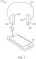
- FIG. 1 shows a first example of a personal audio device according to some embodiments, in the form of headphones 100.
- Headphones 100 include a pair of earpieces 102 and a band 104 that mechanically connects earpieces 102.
- band 104 may also provide electrical connections between earpieces 102.
- Earpieces 102 (also referred to as ear cups) can be made of rigid materials such as rigid plastic and/or metal. Earpieces 102 can be designed and shaped to fit on top of or around the pinnae of the user's ears, covering the concha cavum.
- Earpieces 102 can incorporate one or more speakers to produce sound directed toward the user's ears, control electronics to operate the speakers, a signal interface to receive audio signals in digital or analog format, one or more user input controls (e.g., one or more touch sensitive areas on a surface of one or both of earpieces 102), and other components that can be of generally conventional design.
- cushions 106 can be detachably attached to earpieces 102.
- cushions 106 can have one or more protruding attachment structures (e.g., on the side facing earpieces 102) that snap into complementary slots, holes, clips, or other attachment structures in earpieces 102, or earpieces 102 can have one or more protruding attachment structures that snap into complementary slots, holes, or other attachment structures in cushions 106.
- magnetic attachment structures can be provided in addition to or instead of mechanical attachment structures.
- earpieces 102 can have magnets disposed at various locations on an interface surface that faces cushions 106. Such magnets can be disposed, e.g., near the periphery of earpieces 102.
- Cushions 106 can include metal shunts, magnets, or the like at corresponding locations on the interface surface; any structure that is attracted to the magnets in earpieces 102 can be used. These examples are illustrative, and a particular attachment structure or combination of attachment structures is not critical to understanding the present disclosure.
- Cushions 106 can be formed with a core of foam or other compressible material surrounded by a compliant structural layer that helps to define a shape of a periphery of cushions 106 without imparting rigidity.
- One or more additional textile layers can be applied if desired, e.g., for user comfort, durability, and/or esthetic appearance.
- cushions 106 can incorporate rigid structural elements in areas that do not contact the user's skin during use.
- cushions 106 can include a rigid frame that can be made of plastic or the like, and a rigid frame can facilitate attachment and replacement of cushions 106.
- a frame can incorporate mechanical and/or magnetic attachment structures.
- each cushion 106 can include an identification tag 108 that encodes identification data indicating the type of cushion. Identification tag 108 can be read by earpiece 102, allowing the behavior of headphones 100 to automatically adapt based on the particular type of cushion 106 that is attached at any given time. Specific examples are described below.
- headphones 100 can operate as an accessory to a host device 120.
- Host device 120 can be, for example, a smart phone, a tablet computer, a laptop computer, a desktop computer, a wearable device (e.g., a smart watch), a game console or portable gaming device, or any other electronic device that provides audio output.
- Headphones 100 can connect to host device 120 via a wired or wireless communication channel that supports transfer of audio data (in digital and/or analog formats) from the host device to the personal audio device.
- the communication channel can be bidirectional, allowing headphones 100 to communicate information to host device 120.
- headphones 100 can communicate cushion identification data read from identification tag 108 to host device 120, and host device 120 can modify its behavior based on the cushion identification data received from headphones 100. Specific examples are described below. It should be understood that information other than audio signals and cushion identification data can also be communicated between headphones 100 and host device 120.
- headphones 100 can provide a user input interface that includes, e.g., tactile controls (buttons, touch-sensitive surfaces, or the like) and/or a microphone for voice input, and headphones 100 can communicate user input to host device 120. Such interaction is not relevant to understanding the present disclosure.
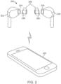
- FIG. 2 shows a second example of a personal audio device according to some embodiments, in the form of earphones 200.
- Earphones 200 include a pair of earpieces 202.
- Earpieces 202 (also referred to as earbuds) can be made of a rigid material such as plastic and/or metal and can incorporate one or more speakers to produce sound, control electronics to operate the speakers, one or more user input controls (e.g., one or more touch sensitive areas on a surface of one or both of earpieces 202), and so on.
- earpieces 202 each have an end portion 204 designed to rest within an outer portion of a user's ear canal, and in some embodiments, the speaker(s) can be located in or adjacent to end portion 204.
- ear tips (also referred to herein as "tips") 206 can be detachably attached to end portion 204.
- tips 206 can include a base portion that can slide over and tightly fit to end portion 204.
- a variety of mechanical and/or magnetic attachment structures may be used, and a particular attachment mechanism is not critical to understanding the present disclosure.
- ear tips 206 can be formed from silicone rubber or other compressible elastic material.
- the body of ear tips 206 can be shaped according to the general dimensions of an ear canal or other portion of an ear, and the body can include an attachment portion that is compatible with the form factor of end portion 204 so that ear tips 206 can be attached to (and removed from) earbuds 202 at end portion 204.
- the body of ear tips 206 can also include a compliant outer lobe or cup that extends outward from the attachment portion, providing a pliable surface to contact the user's ear canal.
- each ear tip 206 can include an identification tag 208 that encodes information data indicating the type of ear tip. Identification tag 208 can be read by earpiece 202, allowing the behavior of earphones 200 to automatically adapt based on the particular type of ear tip 206 that is attached at any given time. Specific examples are described below.
- earbud set 200 can operate as an accessory to a host device 220.
- Host device 220 can be, for example, a smart phone, a tablet computer, a laptop computer, a desktop computer, a wearable device (e.g., a smart watch), a game console or portable gaming device, or any other electronic device that provides audio output.
- Earbuds 202 can connect to host device 220 via a wired or wireless communication channel that supports transfer of audio data (in digital and/or analog formats) from the host device to the personal audio device.
- the communication channel can be bidirectional, allowing earbuds 202 to communicate information to host device 220.
- earbuds 202 can communicate tip identification data read from identification tag 208 to host device 220, and host device 220 can modify its behavior based on the tip identification data received from earbuds 202. Specific examples are described below. It should be understood that information other than audio signals and tip identification data can also be communicated between earbuds 202 and host device 220.
- earbuds 202 can provide a user input interface that includes, e.g., tactile controls (buttons, touch-sensitive surfaces, or the like) and/or a microphone for voice input, and earbuds 200 can communicate user input to host device 120. Such interaction is not relevant to understanding the present disclosure.
- headphones 100 and earbud set 200 are illustrative of personal audio devices having earpieces and cushioning member suitable for use in embodiments of the claimed invention.
- Identification tags as described herein can be incorporated into any cushion, ear tip, or other replaceable user-contacting component (referred to as a "cushioning member") of a personal audio device and can be read by any compatible earpiece to which the cushioning member is attached.
- Earpieces and compatible cushioning members can have a variety of form factors and attachment structures.
- cushion-member identification data can be used locally within the personal audio device to modify one or more of its behaviors. Additionally or instead, the personal audio device can transmit cushion-member identification data to a host device with which the personal audio device is communicably coupled, and the host device can modify one or more of its behaviors in response to the cushion-member identification data.
- identification of cushioning members can be based on an identification tag disposed in or on the cushioning member that can be read using reader circuitry (or a tag sensor) in the earpiece. Examples will now be described. In the following description, some examples are described with reference to ear cups and cushions (e.g., ear cups 102 and cushions 106 of headphones 100 of FIG. 1 ), and some examples are described with reference to earbuds and ear tips (e.g., earbuds 202 and ear tips 206 of FIG. 2 ). It will be appreciated that examples described with reference to ear cups and cushions can be applied to earbuds and ear tips and vice versa.
- FIG. 3 is a simplified block diagram of an earpiece system 300 according to the claimed invention.
- Earpiece system 300 includes an earpiece 302 and a removable cushioning member 306.
- Earpiece 302 (which can be, e.g., ear cup 102 of FIG. 1 or earbud 202 of FIG. 2 ) includes a controller 310, a speaker 312, a tag sensor 314, and may include a communication interface 316.
- Controller 310 can be implemented, e.g., using one or more microprocessors, microcontrollers, field-programmable gate arrays (FPGAs), or other logic circuits of generally conventional design.
- controller 310 can be housed entirely within earpiece 302 (e.g., within ear cup 102 of FIG. 1 or earbud 202 of FIG. 2 ).
- Removable cushioning member 306 (which can be, e.g., cushion 106 of FIG. 1 or ear tip 206 of FIG. 2 ) can include an identification (ID) tag 308.
- ID tag 308 can include any storage medium or structure capable of encoding cushion-member identification data in a physical form that can affect a signal generated by tag sensor 314 of earpiece 302.
- ID tag 308 can be passive or active and can operate with or without an electrical connection. Example implementations of ID tag 308 and corresponding tag sensors 314 are described below.
- Speaker 312 can be an audio speaker of generally conventional design located within earpiece 302 and can include, e.g., an amplifier and a transducer to convert electrical signals to motion of a vibrational element (e.g., a diaphragm).
- Tag sensor 314 can be disposed within earpiece 302 and configured to generate a signal responsive to identification data encoded in identification tag 308 of cushioning member 306; examples are described below.
- Communication interface 316 can include hardware and/or firmware components to enable communication with a host device 350 (e.g., host device 120 of FIG. 1 or host device 220 of FIG. 2 ).
- communication interface 316 can implement standard wireless communication protocols such as Bluetooth, Wi-Fi, or the like.
- a wired communication interface supporting a standard or custom communication protocol or other communication interface can be supported.
- Controller 310 can incorporate a number of logic modules implemented using any appropriate combination of hardware and/or software components.
- audio input module 322 can receive audio data (in digital or analog format) from an audio source.
- the audio source can be, for example, an internet connection, a radio receiver, a microphone positioned to detect ambient sounds in the environment, an analog audio input jack, host device 350 communicating with earpiece 302 via communication interface 316, or any other audio source.
- Signal processing module 324 can perform signal-processing operations on the audio data, including decoding, digital-to-analog conversion, equalization (e.g., selectively adjusting amplitudes associated with different frequency bands), volume control (e.g., adjusting analog signal amplitude), generating audio data associated with an active noise-cancellation operation, mixing of audio data from multiple audio sources (e.g., mixing noise-cancellation audio with audio input such as music or voice data), and/or any other type of audio signal processing that may be desired.
- Audio driver 326 can drive speaker 312 based on an audio signal output from signal processing module 324.
- User input module 328 can support user interaction.
- user input module 328 can be configured to receive and interpret voice commands from the user and/or to detect operation of a user control located on the personal audio device or elsewhere. Based on received user input, user input module 328 can provide instructions to other modules of controller 310, e.g., to select an audio source, control volume, or adjust other settings, or send instructions or data to a host device via communication interface 316. In some embodiments, controller 310 can also include a user output module 330 to provide information or prompts to the user, e.g., using audible, visual, or tactile indicators. Configuration module 332 can store configuration settings (e.g., one or more equalizer profiles, volume limits, noise-cancellation profiles, etc.).
- configuration settings e.g., one or more equalizer profiles, volume limits, noise-cancellation profiles, etc.
- configuration module 332 can modify the behavior of signal processing module 324 and/or other components of controller 310 based on identification data obtained from ID tag 308 of cushioning member 306.
- ID logic module 334 can obtain signals from tag sensor 314 responsive to ID tag 308 and can interpret the signals to "read" the identification data encoded in ID tag 308.
- ID logic module 304 can provide the identification data read from ID tag 308 to configuration module 332, to other modules or components of controller 310, and/or to host device 350 via communication interface 316.
- earpiece system 300 is illustrative and that variations and modifications are possible.
- An earpiece system may include other components not shown in FIG. 3 , such as microphones or touch-sensors to receive user input.
- controller 310 some or all of the signal processing, user input, user output, and configuration operations described above as being performed by controller 310 can instead be performed by appropriate components (including one or more suitably programmed processors) of the host device.
- a personal audio device can include a pair of earpiece systems 300 (e.g., as shown in FIGs. 1 and 2 ).
- one instance of earpiece system 300 may act as a primary earpiece that communicates with the host device and relays signals and/or other information to and from the other (secondary) earpiece; in other embodiments, each instance of earpiece system 300 can communicate directly with the host device, and the pair of earpiece systems might or might not also communicate directly with each other.
- earpiece system 300 is described with reference to particular blocks, it is to be understood that these blocks are defined for convenience of description and are not intended to imply a particular physical arrangement of component parts. Further, the blocks need not correspond to physically distinct components. Blocks can be configured to perform various operations, e.g., by programming a processor or providing appropriate control circuitry, and various blocks might or might not be reconfigurable depending on how the initial configuration is obtained.
- earpiece 302 can read ID tag 308 when tag sensor 314 is brought into proximity with ID tag 308.
- the term "reading" of an identification tag is used herein to refer to the process of obtaining signals from tag sensor 302 responsive to physical characteristics of a particular ID tag 308 and interpreting the signals (e.g., using ID logic 334) to extract identification data.
- the extracted identification data can be, e.g., a numerical value (or bit string) that represents identifying information such as a cushion size, color, material composition, manufacturer, and/or other characteristic(s).
- ID tag 308 and tag sensor 314 can be disposed on or within cushioning member 306 and earpiece 302 in respective locations such that attaching cushioning member 304 to earpiece 302 results in bringing ID tag 308 and tag sensor 314 into proximity to tag sensor 314 such that signals generated by tag sensor 314 are affected by specific properties of ID tag 308 that are different for different cushion types.
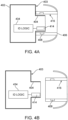
- FIGs. 4A and 4B show simplified cross-section views of an earpiece 402 and an ear tip 406 according to some embodiments.
- Earpiece 402 and ear tip 406 can correspond to earbud 202 and ear tip 206 of FIG. 2 and can implement earpiece system 300 of FIG. 3 .
- ear tip 406 is shown attached to earpiece 402
- ear tip 406 is shown detached from earpiece 402.
- Earpiece 402 can have a proximal surface 403 oriented toward ear tip 406.
- a central portion of proximal surface 403 can project forward to form an end portion 404, which can be shaped as a circular or elliptical cylinder extending from proximal surface 430.
- end portion 404 can be tapered along its length; other shapes may also be used.
- end portion 404 (or other portions of proximal surface 403) can include mechanical retention features (not shown) to hold ear tip 406 in place when ear tip 406 is attached to end portion 404; examples include an elastic ring or spring, a lip, a protrusion or notch, or the like.
- a magnetic retention feature can be provided.
- ear tip 406 can be made of an elastic material, and the elasticity of ear tip 406 can hold ear tip 406 in place over end portion 404.
- End portion 404 can include a tag sensor 414 disposed near a sidewall surface of end portion 404.
- Tag sensor 414 can include various electrical, magnetic, electromagnetic, optical, mechanical, acoustic, or other components; examples are descried below. Depending on implementation, tag sensor 414 can extend around part or all of the circumference of end portion 404.
- Tag sensor 414 can be coupled to an ID logic circuit 434, which need not be in proximity to the surface of end portion 404 and can be disposed anywhere within earpiece 402. ID logic circuit 434 can be configured to interpret signals from tag sensor 414 and to output cushion-member identification data.
- Ear tip 402 can include a sidewall 416, which can define a central opening 407 complementary to end portion 404 of earbud 402.
- the inner surface of sidewall 416 can be shaped as a circular or elliptic cylinder.
- a flexible lobe or cap 420 can extend outward from a front end of sidewall 416. Flexible lobe 420 can be designed to fit into a user's ear canal and to be pliant to conform to the shape of the ear canal.
- Sidewall 416 can be more rigid than flexible lobe 420 and can include retention features such as an elastic ring or spring, a lip, a protrusion or notch, a magnetic retention feature, or the like, and the retention features of sidewall 416 can be complementary to corresponding retention features of end portion 404 of ear tip 402. In some embodiments, the elasticity and static friction of sidewall 416 may serve as retention features.
- Sidewall 416 can include ID tag 408, which can be embedded within sidewall 416 or disposed on the inner surface of sidewall 416.
- ID tag 408 can be or include one or more physical features that are distinct for different cushion types. These physical features can encode identification information specific to a particular type of ear tip 406; examples are described below.
- ID tag 408 can have a cylindrical or curved shape that extends around part or all of the circumference of sidewall 416. This can facilitate reading of ID tag 408 in cases where sidewall 416 is circularly symmetric or does not have a preferred attachment orientation.
- tag sensor 414 when ear tip 406 is attached to earpiece 402, tag sensor 414 is in close enough proximity to ID tag 408 of ear tip 406 to allow tag sensor 414 to generate a signal responsive to the distinctive physical features of identification tag 408; in other words, tag sensor 414 can generate different signals in response to ID tags 408 that have different physical features.
- the arrangement of identification tag 408 and tag sensor 414 is also implementation-dependent. For instance, if ear tip 406 has a preferred rotational orientation, identification tag 408 can be positioned such that it is in proximity to tag sensor 414 when ear tip 406 is in the preferred rotational orientation.
- identification tag 408 and tag sensor 414 can be arranged to allow tag sensor 414 to read identification tag 408 regardless of rotational orientation.
- identification tag 408 can extend around the circumference of sidewall 416, or multiple copies of identification tag 408 can be disposed around the circumference of sidewall 416 such that one copy can be within proximity for reading by tag sensor 414 regardless of rotational orientation.
- tag sensor 414 can extend around the periphery of end portion 404, or multiple copies of tag sensor 414 can be disposed around the periphery of end portion 404 such that one copy can be within proximity of ID tag 408 regardless of rotational orientation.
- Other arrangements that provide proximity between ID tag 408 and tag sensor 414 can also be used.
- tag sensor 414 can be disposed at or near a peripheral portion of proximal surface 403, and identification tag 408 can be disposed at or near a corresponding location on the rear surface of sidewall 416.
- FIG. 5 shows a simplified cross-section view through an earpiece 502 and cushion 506 according to some embodiments.
- Earpiece 502 and cushion 506 can correspond to ear cup 102 and cushion 106 of FIG. 1 .
- earpiece 502 includes magnets 510 disposed at various locations around the periphery of earpiece 502, close to interface surface 503.
- Magnets 510 can be, e.g., rare earth magnets such as NdFeB magnets and can be polarized in a desired orientation.
- Tag sensor 514 can be disposed in a region between magnets 510, near or on interface surface 507.
- Tag sensor 514 can be coupled to an ID logic circuit 534, which need not be in proximity to interface surface 503 and can be disposed anywhere within earpiece 502.
- ID logic circuit 534 can be configured to interpret signals from tag sensor 514 and to output cushion-member identification data.
- Cushion 506 can include attachment structures 512 that align with magnets 510.
- Attachment structures 512 can be magnets polarized to be attracted to magnets 510, or attachment structures 512 can be shunts made of a material that is attracted to magnets 510.
- ID tag 508 can be disposed in a region between attachment structures 512, near or on interface surface 507, in a location such that when attachment structures 512 become magnetically attached to magnets 510, ID tag 508 is in proximity to tag sensor 514, allowing tag sensor 514 to read ID tag 508.
- ID tag 508 and tag sensor 514 can be any distance from attachment structures 512 and magnets 510.
- the shape of attachment structures 512 can be used to represent cushion identification data, and a physically distinct ID tag 508 is not required. (An example of encoding identification data in a magnetic attachment structure is described below.)
- FIGs. 6A and 6B show simplified cross-section views through an earpiece 602 and cushion 606 according to some embodiments.
- Earpiece 602 and cushion 606 can correspond to ear cup 102 and cushion 106 of FIG. 1 .
- cushion 606 is shown detached from earpiece 602
- cushion 606 is shown attached to earpiece 602.
- Earpiece 602 has a proximal surface 603 oriented toward cushion 606.
- Proximal surface 603 can include a recess 605, and a tag sensor 614 can be disposed adjacent to (or on a surface of) recess 605.
- Cushion 606 has a protruding structure 616 that extends outward from a rear surface 617 of cushion 606.
- An ID tag 608 can be positioned within or on a surface of protruding structure 616.
- protruding structure 616 and/or recess 605 can include additional mechanical retention features (not shown) to hold cushion 606 in place when cushion 606 is attached to earpiece 602.
- tag sensor 614 is in proximity to ID tag 608.
- the arrangement is complementary to that shown in FIGs. 4A and 4B , in that in FIGs. 4A and 4B , the protruding part is on the earpiece and holds the tag sensor while the recess is in the cushioning member and holds the ID tag.
- a reverse arrangement can also be provided, in which a recess is formed in cushion 606 and a peg or other protruding part extends from proximal surface 603 of earpiece 602 into the recess.
- Interface surfaces can be curved or flat as desired.
- Mechanical or magnetic retention features for attaching a cushioning member to an earpiece can be located in various positions on the earpiece or cushioning member, and the ID tag and tag sensor can be located within or adjacent to or spaced apart from retention features as desired.
- the ID tag and/or tag sensor can be visible on the interface surface, or they can be covered by surface material.
- An identification tag can be or include any physical structure that encodes identification data.
- an ID tag can be or include any physical structure that can be constructed or formed in multiple versions such that the version of the structure present in each type of cushioning member that is to be distinguished differs from the version present in other types in a way that can be detected by a sensor (i.e., that results in the sensor generating a distinctive signals for each version of the structure).
- Sections 2.2-2.9 describe examples of physical structures that can be used to encode identification data and corresponding tag sensors and ID logic that can read the identification data.
- a cushion can attach to an earpiece magnetically.
- magnetic-attachment components in a cushion can be leveraged to provide an identification tag. An example will now be described.
- FIG. 7A shows a partial exploded view of an earpiece system 700 according to some embodiments.
- Earpiece system 700 incorporates an earpiece 702 (e.g., an implementation of ear cup 102 of FIG. 1 ) and a cushioning member 706 (e.g., an implementation of cushion 106 of FIG. 1 ).
- Earpiece 702 has a housing 710 and a cover 712 that attaches to housing 710.
- Cover 712 can have a peripheral annular shelf 716 and sidewall 718 surrounding a central recessed surface 713.
- Cover 712 can be made of plastic and/or other rigid materials.
- Cushioning member 706 includes an annular cushion element 720 and an annular frame 722 attached to cushion 720.
- Frame 722 can have a peripheral annular shelf 726 and a sidewall 727 shaped and sized such that frame 722 can nest in cover 712 with sidewall 727 of frame 722 abutting sidewall 718 of cover 712 and the underside of annular shelf 726 of frame 722 abutting the upper surface of annular shelf 716 of cover 712.
- One or more magnetic attachment structures can be used to detachably couple (e.g., magnetically couple) cover 712 and frame 722 when the frame 722 is nested within cover 712.
- the securing mechanisms can prevent frame 722 from being removed until a certain force threshold has been reached.
- the magnetic attachment structures can be or include multiple components that engage with one another to attach frame 722 to cover 712.
- a "shunt" element 708, such as metallic plate, may be positioned in one or more corner regions of frame 722, and a magnet array 728 may be positioned in each corresponding region of cover 712.
- Shunt element 708 can be or include a magnet and/or a metallic plate that can be made of steel, iron, nickel, cobalt, stainless steel, aluminum, gold, and/or any other material that can magnetically couple with magnet array 728.
- Magnet array 728 can include one or more magnets, which can be permanent magnets made of ferromagnetic materials such as rare earth magnets (e.g., NdFeB magnets or the like). The magnets of magnet array 728 can have magnetic polarities oriented in specific directions.
- the magnets can be arranged in a Halbach array (e.g., a rotating pattern of magnetic orientations), an alternating array (e.g., adjacent magnets have opposite magnetic orientations), and/or a single pole orientation (e.g., all magnets have the same magnetic orientation).
- Magnet array 728 can generate magnetic flux that can act on shunt element 708 to hold frame 722 in place when frame 722 is nested in cover 712.
- a magnet array 728 can be positioned at each of four (rounded) corner regions of annular shelf 716.
- magnet arrays 728 and/or shunt elements 708 can be arranged such that magnet arrays 728 exert sufficient force to hold frame 722 in place only when cushion 706 is inserted in a "correct" orientation. In embodiments where cushion 706 should be attached in a particular orientation, such an arrangement can aid the user in properly orienting the cushion.
- FIG. 7B shows a partially transparent view of a portion of earpiece system 700 with frame 722 nested in cover 712, illustrating operation of the attachment mechanism.
- Shunt element 708 on annular shelf 726 of cushion 706 is proximate to magnet array 728 on annular shelf 716 of earpiece 702.
- an additional metal shunt 730 can be positioned on cover 712 (e.g., between magnet array 728 and electronic components positioned within earpiece housing 710).
- Metal shunt 730 can prevent or reduce magnetic flux from magnet array 728 from interfering with electronic components contained in earpiece 702.
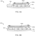
- FIGs. 8A and 8B are simplified perspective views showing an example of magnetic cushion identification according to some embodiments.
- An identification system 800 includes magnet array 728 disposed on a portion of annular shelf 716 of cover 712 (as shown in FIG. 7A ).
- a tag sensor 834 is disposed on annular shelf 716 adjacent to magnet array 728.
- Tag sensor 834 can be, for example, a Hall effect sensor or other sensor capable of detecting magnetic flux from magnet array 728.
- FIG. 8A shows a first shunt element 808a that can be used to indicate a first cushion type
- FIG. 8B shows a second shunt element 808b that can be used to indicate a second cushion type.
- FIG. 8A when a cushion having first shunt element 808a becomes attached to magnet array 728, magnetic flux (indicated by looping arrows 805a) is shunted away from tag sensor 834.
- FIG. 8A shows a geometric property (size and/or shape) of shunt element 708 to encode information data.
- FIG. 8A shows a first shunt element 808a that can be used to indicate a first cushion type
- FIG. 8B shows a second shunt element 808b that can be used to indicate a second cushion type.
- shunt elements 808a, 808b which have different lengths, provide an identification data encoding scheme that distinguishes two cushion types.
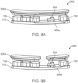
- FIGs. 9A and 9B are simplified perspective views showing another example of magnetic cushion identification according to some embodiments.
- An identification system 900 includes magnet array 728 disposed on a portion of annular shelf 716 of cover 712 (as shown in FIG. 7 ).
- a tag sensor 934 is disposed on annular shelf 716 between magnets of magnet array 728.
- Tag sensor 934 can be, for example, a Hall effect sensor or other sensor capable of detecting magnetic flux from magnet array 728.
- FIG. 9A shows a first shunt element 908a that can be used to indicate a first cushion type
- FIG. 9B shows a second shunt element 908b that can be used to indicate a second cushion type.
- FIG. 9A when a cushion having first shunt element 908a becomes attached to magnet array 728, magnetic flux (indicated by looping arrows 905a) is shunted around tag sensor 934.
- FIG. 9A shows a first shunt element 908a that can be used to indicate a first cushion type
- FIG. 9B shows a second shunt element 908b that can be used to indicate a second cushion type.
- shunt elements 908a, 908b also provide an identification data encoding scheme that distinguishes two cushion types.
- two types of cushions can be distinguished based on whether magnetic flux is shunted away from or through tag sensor 834 or tag sensor 934.
- some embodiments can include multiple instances of magnet array 728 (e.g. one instance at each corner of earpiece 702), with each instance of magnet array 728 having an associated tag sensor (e.g., tag sensor 834 or tag sensor 934).
- Each tag sensor can provide one bit of information, depending on whether the corresponding shunt element shunts the magnetic flux through or away from that sensor.
- each instance of magnet array 728 can include multiple tag sensors disposed between adjacent magnets, and shunt element 708 can be split or not split (as shown in FIGs. 9A-9B ) at various locations, so that a single shunt element can encode multiple bits of information.
- a magnet array may be included in a cushion in addition to or instead of in an earpiece.
- FIG. 10 shows an example of a cushion 1006 according to some embodiments that includes a magnet array 1008.
- Magnet array 1008 includes a number of individual permanent magnets 1010 (or regions of ferromagnetic material), each having a specific magnetic orientation (indicated by arrows).
- Ear cup 1002 can have a tag sensor 1014 that includes an array of Hall effect sensors 1016. Hall effect sensors 1016 can be positioned such that they are adjacent to magnet array 1008 when cushion 1006 is attached to ear cup 1002.
- the pattern of magnetic orientations of magnet array 1008 can encode cushion identification data.
- Hall effect sensors 1016 can respond to the magnetic orientations, enabling ID logic 1018 to extract identification data from the pattern of magnetic orientations.
- each magnet 1010 can encode one bit of identification data.
- an identification tag for a cushion can include a magnet array, and the corresponding tag sensor can include sensors to detect a pattern of magnetic orientation for the magnet array.
- Magnetic-based identification can be implemented in any earpiece system where the cushioning member is magnetically attached to the earpiece, including cushions attached to ear cups and ear tips attached to earbuds. Further, magnetic features similar to those described above can be provided for purposes of identifying the cushioning member, regardless of whether magnetic attachment structures are used.
- an earpiece 302 e.g., ear cup or earbud
- a cushioning member 306 e.g., cushion or ear tip
- FIG. 24 is a flow diagram of a process 2400 that can be performed in an earpiece system such as earpiece system 300 of FIG. 3 according to some embodiments.
- process 2400 can detect the presence of cushioning member 304.
- earpiece 302 may include a proximity or presence sensor that detects when cushioning member 306 is attached by a user. Examples of proximity sensors are known in the art and include, e.g., Hall effect sensors that can respond to a magnetic element disposed within cushioning member 306, optical sensors that can detect occlusion by cushioning member 306, mechanical switches that may be deflected into a different position when cushioning member 306 is attached, or the like.
- earpiece 302 can periodically poll tag sensor 314 to determine whether a cushioning member is present. A particular presence detection mechanism or process is not required.
- process 2400 can obtain identification data (or identification information) from cushioning member 306, e.g., by operating tag sensor 314 and ID logic 334 to read identification tag 308.
- Identification tag 308 can encode identification data using a variety of physical structures, including any of the above-described magnetic, RF-based, resonance-based, optical, acoustic, capacitive, or electrical structures, or any other structure. As used herein, identification data can provide at least some additional information beyond merely indicating presence or absence of a cushioning member.
- the identification data can represent any or all of: a manufacturer identifier; a model identifier; a size identifier; a color identifier; a device-class identifier (e.g., indicating presence or absence of various capabilities or characteristics); a unique serial number; and so on.
- Identification data can be encoded in or on identification tag 308 in any manner that enables earpiece 302 to read or receive the identification data while cushioning member 306 is attached, including any or all of the examples described above.
- process 2400 can communicate the identification data to the host device, e.g., via communication interface 316. Communication of identification data to a host device is not required, and in some embodiments a host device may not be present.
- earpiece system 300 and/or host device 350 can modify a device behavior based on the identification data.
- the modification applies to the earpiece.
- an equalizer setting for earpiece 302 can be selected or modified based (entirely or in part) on the identification data.
- settings related to hearing protection can be modified, such as volume limits, active noise cancellation profiles, or the like.
- earpiece 302 is used as an accessory for host device 350
- behavior of host device 350 can be modified.
- the modified behavior of host device 350 can, but need not, relate to providing audio to earpiece 302.
- the host device may provide a graphical user interface that includes an image of a personal audio device with which the host device is currently interoperating.
- the image can be modified based on the identification data, e.g., by changing the color, shape, or other aspects of appearance of the cushioning member in the image to resemble aspects of the particular cushioning member that is currently attached.
- a personal audio device can include two instances of earpiece system 300 (one for each ear). Where this is the case, each earpiece 302 can read the ID tag 308 of its attached cushioning member 304 and can communicate the identification data to the other earpiece 302 and/or to host device 305. (If the identification data read by the two earpieces is not consistent, e.g., the cushions are of two different types, various actions can be taken. For example, the user can be alerted to the mismatch.
- host device 350 can determine which identification data to use for modifying device behavior.)
- an ID tag 308 may be included in only one cushioning member of a pair, in which case only one earpiece 302 would read an ID tag 308.
- identification data can be used for other purposes in addition to (or instead of) modifying device behavior.
- an earpiece and/or host device can use identification data in a number of ways.
- FIG. 25 shows a table 2500 with examples of mapping an ID value (column 2502) to characteristics of a cushioning member according to some embodiments.
- the cushioning members are ear tips that attach to earbuds. Different ear tips can be distinct in size, color, material, and/or manufacturer.
- Each ID value in column 2502 maps to a different combination of size, color, material, and manufacturer.
- ID tag 308 for a given ear tip can encode one of the defined ID values, and ID logic 334 can use tag sensor 314 to determine which ID value is encoded in a particular ID tag 308.
- Earpiece 302 or host device 350 can decode the ID value, e.g., by referring to a lookup table implementing table 2500, to determine the corresponding characteristics of size, color, material and manufacturer. It should be understood that table 2500 is an example. Depending on the amount (e.g., number of bits) of identification data available in a particular tag, more or fewer characteristics can be distinguished and/or a given characteristic can have more or fewer distinct values.
- an earpiece 302 and/or host device 350 can modify its behavior based on identification data for an attached cushioning member 306.
- the particular modification of behavior in various embodiments can depend on the type of information available, as well as the capabilities of earpiece 302 and/or host device 350. Examples will now be described.
- an earpiece 302 and/or host device 350 can modify its behavior by changing audio output characteristics based on the cushion type identified by the cushion identification data. For instance, it is known in the art that equalizer settings can be used to improve perceived sound quality of a speaker. The audible frequency spectrum can be subdivided into a number of bands, and the relative responses in different bands can be increased or decreased according to the equalizer settings. Optimal equalizer settings may depend in part on the characteristics of the speaker. In the case of personal audio devices such as earphones and headphones, cushioning members made of different materials and/or having different geometries (size and/or shape) can have different effects on sound waves produced by a speaker; hence, the optimal equalizer settings can be different for cushioning members of different types.
- the identification data can include a device class identifier that distinguishes cushion types based on materials and/or geometry.
- the earpiece or host device can store a lookup table that maps each device class identifier to recommended equalizer settings and can select equalizer settings based at least in part on the device class identifier.
- the recommended equalizer settings based on device class identifier can indicate adjustments to a baseline equalizer setting that is determined based on other factors, such as the type of audio being produced (e.g., music vs. spoken word, particular genre of music, etc.) and/or information about the environment.
- some earpieces can provide active noise cancellation.
- active noise cancellation a secondary audio signal is generated that is intended to cancel out ambient sounds that may leak into the user's ear (e.g., airplane engine noise), and the secondary audio signal can be played in isolation or combined (mixed) with a primary audio signal that the user is listening to.
- the effectiveness of noise cancellation in a given earpiece can depend on the properties of the cushioning member; for instance, different cushioning members may admit different amounts of ambient sound, and the amount of admitted sound may depend on frequency.
- a noise cancellation profile used to generate a secondary audio signal for an earpiece can be modified based on identification data (e.g., a device class identifier) obtained from the cushioning member.
- identification data e.g., a device class identifier
- modifying a noise cancellation profile may include enabling or disabling active noise cancellation, or increasing or decreasing the strength of the secondary audio signal either globally or within specific frequency bands.
- some cushioning members may belong to a device class that is designed for use in environments where it is desirable to reduce ambient noise but not to suppress specific sounds (e.g., human speech).
- specific sounds e.g., human speech
- appropriate sound-filtering or active noise cancellation algorithms can be automatically applied.
- some cushioning members may be designed for use by children, who can be particularly vulnerable to hearing damage caused by prolonged exposure to loud sounds.
- volume limits can automatically be applied to the speaker of the personal audio device, which can help to protect the user's ears. It should be understood that volume-limiting operations are not applicable only to children, and volume limits can be associated with any device class.
- some embodiments described above use cushion identification to determine whether a cushioning member is attached to the earpiece.
- One specific example is described above in the context of acoustic identification techniques, but any of the techniques described above for reading an identification tag can also indicate whether an identification tag (and presumably a cushioning member) is present or not.
- an earpiece may be designed for use either with or without a cushioning member, and audio characteristics can be modified based on whether a cushioning member is attached.
- an earpiece may be designed for use only with a cushioning member, and the behavior modification when a cushioning member is not detected can include, e.g., notifying the user to attach a cushioning member or not generating sound in the earpiece (or only a low level of sound) when no cushioning member is present.
- a host device with which a personal audio device interoperates can have a graphical user interface that shows an icon or image representing the personal audio device.
- the icon or image can be modified based on the identification data. For example, if the identification data identifies the shape, color, or other visual characteristics of the cushioning member that is currently attached, the icon or image can be modified to reflect the actual shape, color, or other visual characteristics of the cushioning member.
- device behavior modification is illustrative. Other behavior modifications can be implemented, and different sets of behavior modifications can be associated with different identification data.
- the user can have an option to override the behavior modification, e.g., via a user interface of the host device, via voice command, or the like.
- a cushion identification process might fail to read the cushion identification data due to various circumstances, such as absence of or damage to the identification tag, transient errors in a tag sensor, or the like. Accordingly, some unclaimed examples may implement a default behavior mode when cushion identification fails.
- a default behavior mode can include, for example: operating with default equalizer and/or active noise cancellation profiles; rendering a default cushion image in a graphical user interface; and so on.
- identifying information for a cushioning member that is currently attached to an earpiece can be used to assist a user in selecting a cushioning member to optimize the user's audio experience.
- FIG. 26 shows a flow diagram of a fitting process 2600 according to some unclaimed examples.
- Fitting process 2600 can be implemented, e.g., in a host device that interoperates with an earpiece, such as host device 350 of FIG. 3 interoperating with earpiece system 300.
- process 2600 can prompt the user to attach a cushioning member (e.g., an ear tip) to an earpiece (e.g., an earbud) in order to perform size testing.
- a host device can provide the prompt via a graphical user interface or voice prompt.
- process 2600 can obtain identification data from the ear tip.
- block 2604 can be similar to block 2404 of process 2400 described above, and any of the identification tags and compatible tag sensors and identification logic described above can be used. Identification data can be varied as desired, provided that the identification data enables determination of a size parameter for the ear tip.
- process 2600 can determine the size parameter for the ear tip based on the identification data.
- the identification data may include a numerical value that maps directly to a size (e.g., numerical values 0, 1, 2 can map to sizes small, medium, and large).
- size can be determined by a lookup operation on the identification data (e.g., using table 2500 of FIG. 25 ) or the like.
- process 2600 can perform an audio leakage test. Examples of leakage tests for earpieces are known in the art and can include detecting external sounds leaking in through the earpiece and/or detecting sounds produced by the earpiece leaking out to the environment. A particular test is not relevant to understanding the present disclosure.
- process 2600 can determine whether the leakage test was successful. For instance, success or failure of a leakage test can be defined based on whether the level of sound leakage is below or above some preset threshold. In the event of failure, at block 2612 process 2600 can provide a recommendation for another size to try next. Because process 2600 has determined the size of the ear tip that was tested, the recommendation can be more specific than a general suggestion to try a different size.
- process 2600 can provide a recommendation to try a larger (or smaller) size or to try a specific size. If, at block 2610, the leakage test succeeds, then at block 2614 process 2600 can confirm that the currently-attached size provides appropriate protection against sound leakage.
- process 2600 is illustrative and can be modified.
- Process 2600 can be used with a variety of leakage tests and a variety of earpieces and cushioning members (including cushions for ear cups). Similar processes can also be used to assess whether a particular cushioning member is providing satisfactory audio performance and to recommend a different cushioning member that may provide improved performance.
- different types of cushioning members may be made of different materials that provide different levels of insulation from external sounds, and a recommendation for a cushioning member made of a particular material can be made based on leakage tests and/or user feedback regarding the subjective audio experience.
- a process such as process 2600 can be implemented entirely within the earpiece, e.g., using indicator lights or voice prompts to communicate test results and recommendations.
- Embodiments described above can leverage a variety of data encoding and reading technologies to encode and read identification data for a cushion.
- different technologies can enable different amounts of information to be encoded, from 1 or 2 bits up to several kilobytes. Accordingly, many types of information can be encoded, including materials, manufacturer name, date of manufacture, and/or a unique cushion identifier (e.g., a serial number). Where available, detailed identification data, such as a unique cushion identifier, can be used for a variety of purposes.
- a cushioning member can be made (entirely or in part) of foam and/or elastic materials that may degrade (e.g., become rigid or excessively pliant) after a long period of use or even without use due to aging of the materials.
- the identification data uniquely identifies a specific cushioning member (e.g., by serial number)
- a personal audio device or an associated host device can monitor and track usage history of that cushioning member, e.g., by tracking cumulative hours of use.
- the personal audio device or associated host device can generate a notification to the user when the usage history indicates that the cushioning member may be due for maintenance (e.g., cleaning) or replacement.
- the personal audio device or associated host device can determine whether the cushioning member should be replaced due to age (with or without reference to any usage history information).
- usage monitoring can be performed with less-granular cushion identification data. For example, referring to FIG. 25 , it may be assumed that a particular user has only one set of large red ear tips from manufacturer MFR 1, and usage monitoring can be based on that assumption.
- the behavior of the personal audio device can be modified according to user-specific preferences when a particular cushioning member is identified as being attached. For instance, while a particular cushioning member is attached, a user may adjust equalizer settings, noise cancellation preferences, volume settings, volume limits, or other operating parameters for the personal audio device.
- the personal audio device (or a host device with which the personal audio device interoperates) can save the user preferences in association with the identification data for the cushioning member. The next time the same cushioning member is identified by the personal audio device (or by the host device, as the case may be), the saved user preferences can be automatically retrieved and applied.
- user preferences can be saved in association with identification data at a less granular level; for instance user preferences can be stored in association with an identifier of a specific device class rather than a specific cushioning member, and the stored preferences can be applied whenever a cushioning member is identified as having that device class.
- a host device that saves user preferences associated with a particular cushioning member (or device class) can share the saved preferences with other devices that can act as host devices (e.g., other personal electronic devices belonging to the same user). Accordingly, a user can easily transfer user preferences associated with a particular cushioning member (or device class) to another host device.
- a cushioning member may include active circuitry implementing additional capabilities beyond cushioning and/or sound insulation.
- one or more sensors can be embedded into a cushioning member to detect a user's pulse, temperature, perspiration, or other biometric information. (The particular type or capability of the sensor(s) embedded in a cushioning member may be varied as desired.)
- Identification data for an advanced cushioning member can include data indicating the particular capabilities of the advanced cushioning member (e.g., the sensor type(s) of embedded sensor(s)), and the earpiece (and/or a host device) can modify a behavior accordingly.
- the earpiece can enable supplying of power to the cushioning member when an advanced cushioning member is identified and disable supplying of power otherwise.
- an earpiece (or a host device) can determine when to read sensor data from the cushioning member and/or how to interpret received sensor data. It will be appreciated that a wide variety of advanced capabilities can be selectively enabled or disabled based on identification data obtained from a particular cushioning member.
- ear tips that may be positioned at least partially within the user's ear canal and to cushions that may be worn on the ear or over the ear
- similar principles can be applied to any cushioning member that can be detachably attached to an earpiece of a personal audio device.
- the particular size and shape of a cushioning member or an earpiece can be modified as desired.
- Identification data can range from a small amount of data (e.g., two or three bits) specifying size or color to an arbitrarily long number (which can be represented, e.g., as bit string) that uniquely identifies a particular cushioning member.
- identification data can be structured. For instance, if the identification data is represented as a bit string, one portion of the bit string may identify a device class, another portion may identify a manufacturer, and so on. Lookup tables or the like can also be used to map arbitrary numerical identification data to a particular combination of properties of a cushioning member.
- identification data can be used to modify device behavior, including the production of sound by the earpiece, user interface features, interactions between the earpiece and cushioning member (e.g., reading sensor data), and so on. Identification data can also be used to monitor the condition of a particular cushioning member and to notify the user when a cushioning member may benefit from maintenance (e.g., cleaning) or replacement. Other behavior modifications and/or user-supportive operations can be implemented based on the identification data.
- a personal audio device may include a pair of earpieces of like design (e.g., as shown in FIGs. 1 and 2 ) and that cushioning members may likewise be provided in pairs of like design.
- an identification tag can be included in either or both cushioning members of the pair, and reader circuitry to read the identification tag may be included in either or both earpieces. If reader circuitry in the two earpieces of a pair detect a discrepancy in identification data between their respective cushioning members (e.g., identification data indicating different device classes or sizes), various responsive actions can be taken.
- the user can be notified of the discrepancy; audio settings for the two earpieces can be modified differently based on the identification data of their respective cushion members; or audio settings for both earpieces can be selected based on blending audio settings associated with the two cushioning members.
- Computer programs incorporating various features described herein may be encoded and stored on various computer readable storage media; suitable media include magnetic disk or tape, optical storage media such as compact disk (CD) or DVD (digital versatile disk), flash memory, and other non-transitory media.
- Computer readable media encoded with the program code may be packaged with a compatible electronic device, or the program code may be provided separately from electronic devices (e.g., via Internet download or as a separately packaged computer-readable storage medium).
- the identification data can uniquely identify a particular cushioning member that belongs to a particular user; where this is the case, the identification data might be regarded as personally identifiable information. It is well understood that the use of personally identifiable information should follow privacy policies and practices that are generally recognized as meeting or exceeding industry or governmental requirements for maintaining the privacy of users. In particular, personally identifiable information should be managed and handled so as to minimize risks of unintentional or unauthorized access or use, and the nature of authorized use should be clearly indicated to users. For instance, in some embodiments, identification data for a cushion or tip need not be provided to any entity other than the earpiece or (optionally) a user-owned host device with which the earpiece interoperates. Users may be informed of and prompted to opt in to any sharing of data that may occur.
Landscapes
- Engineering & Computer Science (AREA)
- Signal Processing (AREA)
- Physics & Mathematics (AREA)
- Acoustics & Sound (AREA)
- General Health & Medical Sciences (AREA)
- Health & Medical Sciences (AREA)
- Manufacturing & Machinery (AREA)
- Neurosurgery (AREA)
- Otolaryngology (AREA)
- Computer Networks & Wireless Communication (AREA)
- Headphones And Earphones (AREA)
- Telephone Set Structure (AREA)
- Circuit For Audible Band Transducer (AREA)
Description
- This application claims priority to the following applications:
U.S. Application No. 62/902,239, filed September 18, 2019 U.S. Application No. 62/906,624, filed September 26, 2019 U.S. Application No. 62/925,952, filed October 25, 2019 U.S. Application No. 17/023,237, filed September 16, 2020 . - This disclosure relates generally to personal audio devices such as earbuds and headphones and in particular to identification of removable cushioning members such as ear tips and cushions by a personal audio device that can support adaptive behavior based on the presence of a particular cushioning member.
- A "personal audio device" refers to a device that produces sound to be heard by an individual user while limiting the audibility of that sound in an environment around the user. Examples of personal audio devices include headphones and earphones. Headphones generally include one or two audio-producing earpieces (also referred to as "ear cups") that are designed to be worn over the ear or on the ear. The ear cups are typically connected to a headband, which can help to hold the ear cups in place and can also provide an electrical connection between the ear cups. The ear cups are designed to be worn such that an audio-generating speaker contained in each ear cup directs sound toward an ear of the wearer. A cushion made of compliant material is typically provided around a peripheral portion of the ear cup in order to provide spacing between the speaker and the user's ear and to provide user comfort while wearing the headphones. The cushion may also provide sound insulation, preventing sound generated by the ear cups from leaking into the environment and/or preventing external sound from reaching the user's ears. Earphones generally include one or two audio-producing earpieces (also referred to as "earbuds") that are designed to be inserted into the user's ears (either into the ear canal or resting against the concha cavum) such that an audio-generating speaker contained in the earpiece (or earbud) is oriented toward the ear canal. An ear tip (also sometimes referred to herein as a "tip") made of soft material may be provided to cover at least the portion of the earbud that rests against the user's skin. Similarly to cushions of ear cups, an ear tip of an earbud may increase user comfort and provide at least some degree of sound insulation.
-
US 2018/376232 is directed to an audio headset capable of identifying the type of ear cushion coupled to the headphones. Electric identification contacts are included in the ear cushion which facilitate the identification when attached to headphones. -
US 2015/146880 describes enhanced safety headphones for listening to audio and music, wherein the wearer decides the degree of sound isolation desired. -
JP 2009212772 -
US 2017/251313 is directed to a percutaneous bone conduction hearing device which uses a multipole magnetic coupling system to determine which side of the head the device is placed on. - The invention is set out in the appended set of claims. Disclosed herein are various embodiments related to personal audio devices (e.g., headphones, earphones) having an earpiece (e.g., an ear cup or earbud) with a removable cushioning member (e.g., headphone cushions or earphone tips). The cushioning member can include an identification tag that encodes identification data indicative of one or more properties or characteristics of the cushioning member (e.g., size, material, color, manufacturer, etc.). When the cushioning member is attached to the earpiece, the earpiece reads the identification data from the identification tag. The earpiece includes a tag sensor that generates a signal responsive to an electrical, magnetic, electromagnetic, optical, geometrical, or mechanical characteristic of the identification tag and an identification (ID) logic circuit that decodes the signal from the tag sensor to extract the identification data. In some embodiments, based on the identification data, a controller of the personal audio device can modify the behavior of the earpiece. In some embodiments, the earpiece can communicate the identification data to a host device with which the personal audio device is communicably coupled (e.g., a phone, computer, media player, gaming device, or other device that can provide audio output to the personal audio device), and the host device can modify its behavior and/or a behavior of the earpiece based on the identification data.
- According to the claimed invention, a cushioning member for an earpiece of a personal audio device includes a body having a first surface to be placed in contact with a user's ear area and a second surface, at least the first surface being made of a compliant material; an attachment structure disposed on the second surface and configured to attach the cushioning member to an earpiece of a personal audio device; and may include an identification tag disposed at or near the second surface such that when the cushioning member is attached to the earpiece, the identification tag is in proximity to a tag sensor disposed in the earpiece. The identification tag can encode identification data for the cushioning member. The body can be shaped, e.g., as an ear cushion for a headphone or as an ear tip for an earphone.
- Identification tags can be implemented using a number of different structures and techniques. In some embodiments the identification tag can include any or all of: an arrangement of one or more magnets that encodes the identification data; a magnetic shunt having a shape that encodes the identification data. In unclaimed examples, the identification tag can include any or all of an inductive coil tuned to a resonant frequency, wherein the resonant frequency maps to the identification data; a surface optically encoded with the identification data; a passive near-field communication (NFC) or radio-frequency identification (RFID) tag encoded with the identification data; a pattern of metal and/or non-metal regions where presence or absence of metal in each region encodes the identification data; a feature affecting an acoustic property of the cushioning member; one or more electrical contacts coupled to an identification circuit element (e.g., a resistor or a coupling or absence of coupling to ground). In some embodiments, an identification tag is disposed within or on the attachment structure of the cushioning member.
- According to the claimed invention, an earpiece for a personal audio device includes: a housing having a proximal surface; a speaker disposed in the housing; an attachment structure disposed on the proximal surface and configured to attach to a cushioning member; a tag sensor disposed at or near the proximal surface and configured to generate a signal responsive to an identification tag of the cushioning member; identification logic coupled to the tag sensor and configured to determine identification data for the cushioning member based on the signal from the tag sensor; and a controller coupled to the identification logic which may be configured to modify a device behavior of the earpiece in response to the identification data. In some embodiments, the earpiece can also include a communication interface configured to communicate the identification data to a host device. The housing can be shaped, e.g., as an ear cup or earbud or the like. In some embodiments, the tag sensor can be disposed within or on the attachment structure.
- A tag sensor can be implemented using a number of different sensors and technique. For instance, in some embodiments, a tag sensor can include a magnetic sensor configured to determine a magnetic orientation for each of one or more magnets of the identification tag. In some embodiments, the attachment structure can include one or more magnets and the tag sensor can include a magnetic sensor (e.g., a Hall sensor) configured to determine a geometric characteristic of a shunt element attached to the one or more magnets, where the geometric characteristic of the shunt element can encode identification information and thus serve as an identification tag.
- According to the claimed invention, a cushioning member for an earpiece of a personal audio device comprises: a body having a first surface to be placed in contact with a user's ear area and a second surface, at least the first surface being made of a compliant material; and a first magnetic attachment structure disposed on the second surface and configured to attach the cushioning member to an earpiece of a personal audio device. According to the claimed invention, a geometric property (e.g., shape and/or size) of the first magnetic attachment structure encodes identification data for the cushioning member. For example, the first magnetic attachment structure can include a metallic plate that shunts magnetic fields, and the geometric property includes a size of the first magnetic attachment structure and/or a presence or absence of a gap or split in the first magnetic attachment structure. In some embodiments, multiple magnetic attachment structures, including the first magnetic attachment structure, can be disposed on the second surface of the cushioning member, and a respective geometric structure of each of the plurality of magnetic attachment structures can encode at least one bit of identification data. The magnetic attachment structures can be positioned as desired. For example, the body of the cushioning member can have corner regions, with one of the magnetic attachment structures positioned in each of the corner regions.
- According to some embodiments, an earpiece for a personal audio device can comprise: a housing having a proximal surface; a speaker disposed in the housing; a first magnetic attachment structure disposed on the proximal surface and configured to attach to a cushioning member; a first tag sensor disposed at or near the proximal surface and configured to generate a signal responsive to a magnetic flux affected by attachment of the cushioning member; identification logic coupled to the first tag sensor and configured to determine identification data for the cushioning member based at least in part on the signal from the first tag sensor; and a controller coupled to the identification logic and configured to receive the identification data from the identification logic. In some embodiments, the first magnetic attachment structure can include an array of magnets configured to form a magnetic flux loop when a magnetic shunt element of the cushioning member is in proximity to the array of magnets. The array of magnets can be configured such that the magnetic flux loop is directed either through or away from the first tag sensor, depending on a geometric property of the magnetic shunt element. For instance, the first tag sensor can include a Hall effect sensor placed adjacent to the array of magnets and/or a Hall effect sensor placed between two magnets in the array of magnets. In some embodiments, multiple magnetic attachment structures, including the first magnetic attachment structure, can be disposed on the proximal surface and each of the magnetic attachment structures can have an associated tag sensor; each of the tag sensors can provide at least one bit of identification data to the identification logic.
- According to some embodiments, an earpiece system for a personal audio device can comprise a cushioning member and an earpiece. The cushioning member has: a body having a first surface to be placed in contact with a user's ear area and a second surface, at least the first surface being made of a compliant material; and a first cushion-side magnetic attachment structure disposed on the second surface and configured to attach the cushioning member to an earpiece of a personal audio device, where a geometric property (e.g., size and/or shape) of the first cushion-side magnetic attachment structure encodes identification data for the cushioning member. The earpiece has: a housing having a proximal surface; a speaker disposed in the housing; a first earpiece-side magnetic attachment structure disposed on the proximal surface and configured to attach to the first cushion-side magnetic attachment structure; a first tag sensor disposed at or near the proximal surface and configured to generate a signal responsive to a magnetic flux affected by attachment of the cushioning member; identification logic coupled to the first tag sensor and configured to determine identification data for the cushioning member based at least in part on the signal from the first tag sensor; and a controller coupled to the identification logic and configured to receive the identification data from the identification logic. In some embodiments, the first cushion-side magnetic attachment structure comprises a metallic plate that shunts magnetic fields. In some embodiments, the geometric property includes a size of the first cushion-side magnetic attachment structure and/or a presence or absence of a gap or split in the first cushion-side magnetic attachment structure. In some embodiments, the first earpiece-side magnetic attachment structure can include an array of magnets configured to form a magnetic flux loop when the first cushion-side magnetic attachment structure of the cushioning member is in proximity to the array of magnets, and the first tag sensor can include a Hall effect sensor placed adjacent to one or more of the magnets in the array of magnets. The geometric property of the cushion-side magnetic attachment structure can shape the magnetic flux loop to shunt the magnetic flux either toward or away from the tag sensor. In some embodiments, multiple cushion-side magnetic attachment structures, including the first cushion-side magnetic attachment structure, can disposed on the second surface of the cushioning member, and a respective geometric structure of each of the plurality of cushion-side magnetic attachment structures can encode at least one bit of identification data; likewise, multiple earpiece-side magnetic attachment structures, including the first earpiece-side magnetic attachment structure, can be disposed on the proximal surface, and each of the plurality of earpiece-side magnetic attachment structures can have an associated tag sensor, where each tag sensor can provide at least one bit of identification data to the identification logic.
- Given a particular encoding structure, various types of identification data can be encoded in an identification tag in a cushioning member and read by a tag sensor and identification logic in an earpiece. For instance, identification data can indicate one or more of: a size of the cushioning member; a color of the cushioning member; a device class of the cushioning member; a manufacturer of the cushioning member; a model identifier of the cushioning member; a unique identifier of the cushioning member; and/or an active capability supported by the cushioning member. In some embodiments, the identification data can be a parameter value that can be mapped to indicia of one or more attributes of the cushioning member (e.g., size, color, device class, manufacturer, model, unique identifier, etc.).
- According to some unclaimed examples, a method of identifying a cushioning member for a personal audio device can include detecting, by an earpiece of a personal audio device, presence of a cushioning member; operating, by the earpiece of the personal audio device, reader circuitry to read identification data from an identification tag located on the cushioning member; and modifying a device behavior based at least in part on the identification data. In some embodiments, the earpiece of the personal device can modify its own behavior in response to the identification data. Additionally or instead, the earpiece of the personal device can transmit the identification data to a host device with which the personal audio device interoperates, and the host device can modify its own behavior and/or the behavior of the personal audio device in response to the identification data.
- Various types of behavior modification can be implemented in response to identification data. For example, modifying the device behavior can include modifying an audio characteristic including any or all of: modifying an equalizer setting for the personal audio device; modifying an active noise cancellation profile of the personal audio device; applying a sound filtering algorithm for the personal audio device; modifying a volume limit for the personal audio device; and/or applying a saved user preference associated with the identification data. In some unclaimed examples where the personal audio device interoperates with a host device, the host device can modify an image of the personal audio device in a graphical user interface of the host device based at least in part on the identification data. In some unclaimed examples where the identification data includes data indicating whether the cushioning member supports an advanced capability, modifying the device behavior includes enabling or disabling the advanced capability based on the identification data. In some embodiments where the identification data includes data indicating a size of the cushioning member, modifying the device behavior includes using the size of the cushioning member in a cushioning-member fitting process.
- The following detailed description, together with the accompanying drawings, will provide a better understanding of the nature and advantages of the claimed invention.
-
-
FIG. 1 shows a first example of a personal audio device according to some embodiments. -
FIG. 2 shows a second example of a personal audio device according to some embodiments. -
FIG. 3 shows a simplified block diagram of an earpiece system according to the claimed invention. -
FIGs. 4A-4C show simplified cross-section views of an earpiece and an ear tip according to some embodiments. -
FIG. 5 shows a simplified cross-section view through an earpiece and cushion according to some embodiments. -
FIGs. 6A and 6B show simplified cross-section views through an earpiece and cushion according to some embodiments. -
FIG. 7A shows a partial exploded view of an earpiece system according to some embodiments. -
FIG. 7B shows a partially transparent view of a portion of an earpiece according to some embodiments. -
FIGs. 8A and 8B are simplified perspective views showing an example of magnetic cushion identification according to some embodiments. -
FIGs. 9A and 9B are simplified perspective views showing another example of magnetic cushion identification according to some embodiments. -
FIG. 10 shows a simplified cross-section view of an ear cup and cushion incorporating magnetic cushion identification according to some embodiments. -
FIG. 11 shows a simplified view of an ear cup and cushion incorporating NFC circuits according to some unclaimed examples. -
FIGs. 12A and 12B show a simplified cross-section view of an earbud and ear tip incorporating NFC circuits according to various unclaimed examples. -
FIG. 13A shows a simplified view of an earcup incorporating a sensor coil array according to some unclaimed examples, andFIG. 13B shows a more detailed view of a layout of the sensor coil array. -
FIG. 13C shows a schematic circuit diagram of a sensor coil array and ID logic circuit according to some unclaimed examples. -
FIG. 14 shows a simplified view of a cushion incorporating a tag element readable using a sensor coil array according to some unclaimed examples. -
FIG. 15 shows a more detailed view of a tag element overlying a sensor coil array according to some unclaimed examples. -
FIG. 16 shows a simplified view of an ear cup and cushion incorporating resonant-circuit-based identification according to some unclaimed examples. -
FIGs. 17A and 17B show examples of resonant circuits and reader circuits that can be used according to some unclaimed examples. -
FIGs. 18A and 18B illustrate an arrangement for an optical sensor in an ear cup according to some unclaimed examples. -
FIGs. 19A and19B show examples of optical encoding of identification data in a cushion according to various unclaimed examples. -
FIG. 20 shows an example of an earbud and ear tip according to some embodiments. -
FIG. 21 shows a flow diagram of a process for acoustic identification according to some unclaimed examples. -
FIG. 22 shows a simplified view of an ear cup and cushion implementing resistance-based identification data according to some unclaimed examples. -
FIG. 23 shows a simplified view of an ear cup and cushion implementing contact-based identification data according to some unclaimed examples. -
FIG. 24 shows a flow diagram of a cushion-identification process that can be performed in an earpiece system according to some embodiments. -
FIG. 25 shows a table with examples of mapping an ID value to characteristics of a cushioning component according to some embodiments. -
FIG. 26 shows a flow diagram of a fitting process for an ear tip according to some embodiments. - Disclosed herein are various embodiments related to personal audio devices (e.g., headphones, earphones) having an earpiece (e.g., an ear cup or earbud) with a removable cushioning member (e.g., headphone cushions or earphone tips). The cushioning member can include an identification tag that encodes identification data indicative of one or more properties or characteristics of the cushioning member (e.g., size, material, color, manufacturer, etc.). When the cushioning member is attached to the earpiece, the earpiece can read the identification data from the identification tag. For example, the earpiece can include a tag sensor that generates a signal responsive to an electrical, magnetic, electromagnetic, optical, geometrical, or mechanical characteristic of the identification tag and an identification (ID) logic circuit that decodes the signal from the tag sensor to extract the identification data. In some embodiments, based on the identification data, a controller of the personal audio device can modify the behavior of the earpiece. In some embodiments, the earpiece can communicate the identification data to a host device with which the personal audio device is communicably coupled (e.g., a phone, computer, media player, gaming device, or other device that can provide audio output to the personal audio device), and the host device can modify its behavior and/or a behavior of the earpiece based on the identification data.
- In various embodiments, the identification tag in a cushioning member can be a "passive" tag that does not require a power source in order to be read by an earpiece. For example, the identification tag can be implemented using a piece of magnetic material or a magnetic shunt whose presence and/or geometry can be detected using a magnetic sensor (e.g., Hall effect sensor) located in the earpiece.
- In various embodiments, the identification data obtained from an identification tag can include or represent any information that distinguishes one cushioning member from another. For example, the identification data can represent any or all of: a manufacturer identifier; a model identifier; a size identifier; a color identifier; a device-class identifier (e.g., indicating presence or absence of various capabilities or characteristics); a unique serial number; and/or other information as desired. In some embodiments, an identification tag can encode a numerical value that can be mapped by ID logic in the earpiece (or in a connected host device) to a particular set of characteristics of the cushioning member.
- In various embodiments, the earpiece and/or a host device can change different aspects of their behavior based on the identification data. For example, an equalizer setting can be selected or modified based on the identification data. Hearing-protection settings can be modified, including, e.g., limiting the speaker volume of the earpiece, modifying an active noise cancellation profile for the earpiece, and so on. User interface behavior can also be modified. For instance, if a host device has a display that shows an image of the personal audio device, the displayed image can be modified to match the currently-attached cushioning member.
- In various embodiments, the earpiece and/or a host device can use the identification data in connection with monitoring the condition of the cushioning member. For example, a host device can track the age or total lifetime usage of a particular cushioning member and suggest replacement at an appropriate interval.
- In various examples, the earpiece and/or a host device can use the identification data to assist with sizing of a cushioning member. For example, ear tips, which fit into a user's ear, may come in several sizes to accommodate variations in the size of human ears. During fitting of ear tips, an audio leakage test can be performed to assess the fit of a particular tip. Based on the results of the leakage test and identification data indicating a size of the tested tip, the earpiece (or a host device) can suggest a specific tip size to try next.
- In various examples, the earpiece and/or a host device can use the identification data to activate or deactivate advanced capabilities that may be supported by certain cushioning members. For example, it is contemplated that an advanced cushion or ear tip (or other cushioning member) may include one or more biometric monitoring devices such as a pulse sensor, temperature sensor, or moisture (e.g., perspiration) sensor that can provide sensor data to the earpiece, which in turn can communicate the sensor data to a host device or use the data internally (e.g., to generate an audible indication related to the sensor data). Based on whether the identification data indicates that the cushioning member supports a particular monitoring capability, the earpiece can automatically enable or disable its receiver(s) for the monitoring data.
-
FIG. 1 shows a first example of a personal audio device according to some embodiments, in the form ofheadphones 100.Headphones 100 include a pair ofearpieces 102 and aband 104 that mechanically connectsearpieces 102. In some embodiments,band 104 may also provide electrical connections betweenearpieces 102. Earpieces 102 (also referred to as ear cups) can be made of rigid materials such as rigid plastic and/or metal.Earpieces 102 can be designed and shaped to fit on top of or around the pinnae of the user's ears, covering the concha cavum.Earpieces 102 can incorporate one or more speakers to produce sound directed toward the user's ears, control electronics to operate the speakers, a signal interface to receive audio signals in digital or analog format, one or more user input controls (e.g., one or more touch sensitive areas on a surface of one or both of earpieces 102), and other components that can be of generally conventional design. - To provide user comfort, cushions 106 can be detachably attached to earpieces 102. For example, cushions 106 can have one or more protruding attachment structures (e.g., on the side facing earpieces 102) that snap into complementary slots, holes, clips, or other attachment structures in
earpieces 102, orearpieces 102 can have one or more protruding attachment structures that snap into complementary slots, holes, or other attachment structures incushions 106. In some embodiments, magnetic attachment structures can be provided in addition to or instead of mechanical attachment structures. For example,earpieces 102 can have magnets disposed at various locations on an interface surface that faces cushions 106. Such magnets can be disposed, e.g., near the periphery ofearpieces 102.Cushions 106 can include metal shunts, magnets, or the like at corresponding locations on the interface surface; any structure that is attracted to the magnets inearpieces 102 can be used. These examples are illustrative, and a particular attachment structure or combination of attachment structures is not critical to understanding the present disclosure. -
Cushions 106 can be formed with a core of foam or other compressible material surrounded by a compliant structural layer that helps to define a shape of a periphery ofcushions 106 without imparting rigidity. One or more additional textile layers can be applied if desired, e.g., for user comfort, durability, and/or esthetic appearance. In some embodiments, cushions 106 can incorporate rigid structural elements in areas that do not contact the user's skin during use. For example, cushions 106 can include a rigid frame that can be made of plastic or the like, and a rigid frame can facilitate attachment and replacement ofcushions 106. For example, a frame can incorporate mechanical and/or magnetic attachment structures. - For purposes of the present disclosure, it is assumed that multiple types of
cushions 106 that are compatible with thesame headphones 102 exist. In various embodiments, different types ofcushions 106 may be distinct from each other in terms of size, color, materials, audio performance (e.g., how effectively a particular cushion blocks ambient sound), and/or other characteristics. It is also assumed that different types ofcushions 106 are user-interchangeable; that is, a user may attachcushions 106 of different types to thesame earpieces 102 at different times. To facilitate identification of which cushions 106 are currently attached toearpieces 102, eachcushion 106 can include anidentification tag 108 that encodes identification data indicating the type of cushion.Identification tag 108 can be read byearpiece 102, allowing the behavior ofheadphones 100 to automatically adapt based on the particular type ofcushion 106 that is attached at any given time. Specific examples are described below. - In some embodiments,
headphones 100 can operate as an accessory to ahost device 120.Host device 120 can be, for example, a smart phone, a tablet computer, a laptop computer, a desktop computer, a wearable device (e.g., a smart watch), a game console or portable gaming device, or any other electronic device that provides audio output.Headphones 100 can connect tohost device 120 via a wired or wireless communication channel that supports transfer of audio data (in digital and/or analog formats) from the host device to the personal audio device. In some embodiments, the communication channel can be bidirectional, allowingheadphones 100 to communicate information tohost device 120. For example,headphones 100 can communicate cushion identification data read fromidentification tag 108 tohost device 120, andhost device 120 can modify its behavior based on the cushion identification data received fromheadphones 100. Specific examples are described below. It should be understood that information other than audio signals and cushion identification data can also be communicated betweenheadphones 100 andhost device 120. For example,headphones 100 can provide a user input interface that includes, e.g., tactile controls (buttons, touch-sensitive surfaces, or the like) and/or a microphone for voice input, andheadphones 100 can communicate user input tohost device 120. Such interaction is not relevant to understanding the present disclosure. -
FIG. 2 shows a second example of a personal audio device according to some embodiments, in the form ofearphones 200.Earphones 200 include a pair ofearpieces 202. Earpieces 202 (also referred to as earbuds) can be made of a rigid material such as plastic and/or metal and can incorporate one or more speakers to produce sound, control electronics to operate the speakers, one or more user input controls (e.g., one or more touch sensitive areas on a surface of one or both of earpieces 202), and so on. In this example,earpieces 202 each have anend portion 204 designed to rest within an outer portion of a user's ear canal, and in some embodiments, the speaker(s) can be located in or adjacent to endportion 204. - To provide user comfort, ear tips (also referred to herein as "tips") 206 can be detachably attached to end
portion 204. For example,tips 206 can include a base portion that can slide over and tightly fit to endportion 204. As withearcups 102 andcushions 106 ofFIG. 1 , a variety of mechanical and/or magnetic attachment structures may be used, and a particular attachment mechanism is not critical to understanding the present disclosure. - In some embodiments,
ear tips 206 can be formed from silicone rubber or other compressible elastic material. The body ofear tips 206 can be shaped according to the general dimensions of an ear canal or other portion of an ear, and the body can include an attachment portion that is compatible with the form factor ofend portion 204 so thatear tips 206 can be attached to (and removed from)earbuds 202 atend portion 204. The body ofear tips 206 can also include a compliant outer lobe or cup that extends outward from the attachment portion, providing a pliable surface to contact the user's ear canal. - For purposes of the present disclosure, it is assumed that multiple types of
ear tips 206 that are compatible with thesame earpieces 202 exist. In various embodiments, different types ofear tips 206 may be distinct from each other in terms of size, color, materials, audio performance (e.g., how effectively a particular ear tip blocks external sound), and/or other characteristics. It is also assumed that different types ofear tips 206 are user-interchangeable; that is, a user may attachear tips 206 of different types to thesame earpiece 202 at different times. To facilitate identification of whichear tips 206 are currently attached toearpieces 202, eachear tip 206 can include anidentification tag 208 that encodes information data indicating the type of ear tip.Identification tag 208 can be read byearpiece 202, allowing the behavior ofearphones 200 to automatically adapt based on the particular type ofear tip 206 that is attached at any given time. Specific examples are described below. - Similarly to
headphones 100, earbud set 200 can operate as an accessory to ahost device 220.Host device 220 can be, for example, a smart phone, a tablet computer, a laptop computer, a desktop computer, a wearable device (e.g., a smart watch), a game console or portable gaming device, or any other electronic device that provides audio output.Earbuds 202 can connect tohost device 220 via a wired or wireless communication channel that supports transfer of audio data (in digital and/or analog formats) from the host device to the personal audio device. In some embodiments, the communication channel can be bidirectional, allowingearbuds 202 to communicate information tohost device 220. For example,earbuds 202 can communicate tip identification data read fromidentification tag 208 tohost device 220, andhost device 220 can modify its behavior based on the tip identification data received fromearbuds 202. Specific examples are described below. It should be understood that information other than audio signals and tip identification data can also be communicated betweenearbuds 202 andhost device 220. For example,earbuds 202 can provide a user input interface that includes, e.g., tactile controls (buttons, touch-sensitive surfaces, or the like) and/or a microphone for voice input, andearbuds 200 can communicate user input tohost device 120. Such interaction is not relevant to understanding the present disclosure. - It is to be understood that
headphones 100 and earbud set 200 are illustrative of personal audio devices having earpieces and cushioning member suitable for use in embodiments of the claimed invention. Identification tags as described herein can be incorporated into any cushion, ear tip, or other replaceable user-contacting component (referred to as a "cushioning member") of a personal audio device and can be read by any compatible earpiece to which the cushioning member is attached. Earpieces and compatible cushioning members can have a variety of form factors and attachment structures. - In some embodiments, cushion-member identification data can be used locally within the personal audio device to modify one or more of its behaviors. Additionally or instead, the personal audio device can transmit cushion-member identification data to a host device with which the personal audio device is communicably coupled, and the host device can modify one or more of its behaviors in response to the cushion-member identification data.
- According to various embodiments, identification of cushioning members can be based on an identification tag disposed in or on the cushioning member that can be read using reader circuitry (or a tag sensor) in the earpiece. Examples will now be described. In the following description, some examples are described with reference to ear cups and cushions (e.g., ear cups 102 and
cushions 106 ofheadphones 100 ofFIG. 1 ), and some examples are described with reference to earbuds and ear tips (e.g.,earbuds 202 andear tips 206 ofFIG. 2 ). It will be appreciated that examples described with reference to ear cups and cushions can be applied to earbuds and ear tips and vice versa. -
FIG. 3 is a simplified block diagram of anearpiece system 300 according to the claimed invention.Earpiece system 300 includes anearpiece 302 and aremovable cushioning member 306. Earpiece 302 (which can be, e.g.,ear cup 102 ofFIG. 1 orearbud 202 ofFIG. 2 ) includes acontroller 310, aspeaker 312, atag sensor 314, and may include acommunication interface 316.Controller 310 can be implemented, e.g., using one or more microprocessors, microcontrollers, field-programmable gate arrays (FPGAs), or other logic circuits of generally conventional design. In some embodiments,controller 310 can be housed entirely within earpiece 302 (e.g., withinear cup 102 ofFIG. 1 orearbud 202 ofFIG. 2 ). - Removable cushioning member 306 (which can be, e.g., cushion 106 of
FIG. 1 orear tip 206 ofFIG. 2 ) can include an identification (ID)tag 308.ID tag 308 can include any storage medium or structure capable of encoding cushion-member identification data in a physical form that can affect a signal generated bytag sensor 314 ofearpiece 302.ID tag 308 can be passive or active and can operate with or without an electrical connection. Example implementations ofID tag 308 andcorresponding tag sensors 314 are described below. -
Speaker 312 can be an audio speaker of generally conventional design located withinearpiece 302 and can include, e.g., an amplifier and a transducer to convert electrical signals to motion of a vibrational element (e.g., a diaphragm).Tag sensor 314 can be disposed withinearpiece 302 and configured to generate a signal responsive to identification data encoded inidentification tag 308 of cushioningmember 306; examples are described below.Communication interface 316 can include hardware and/or firmware components to enable communication with a host device 350 (e.g.,host device 120 ofFIG. 1 orhost device 220 ofFIG. 2 ). For example,communication interface 316 can implement standard wireless communication protocols such as Bluetooth, Wi-Fi, or the like. In addition or instead, a wired communication interface supporting a standard or custom communication protocol or other communication interface can be supported. -
Controller 310 can incorporate a number of logic modules implemented using any appropriate combination of hardware and/or software components. For example,audio input module 322 can receive audio data (in digital or analog format) from an audio source. The audio source can be, for example, an internet connection, a radio receiver, a microphone positioned to detect ambient sounds in the environment, an analog audio input jack,host device 350 communicating withearpiece 302 viacommunication interface 316, or any other audio source.Signal processing module 324 can perform signal-processing operations on the audio data, including decoding, digital-to-analog conversion, equalization (e.g., selectively adjusting amplitudes associated with different frequency bands), volume control (e.g., adjusting analog signal amplitude), generating audio data associated with an active noise-cancellation operation, mixing of audio data from multiple audio sources (e.g., mixing noise-cancellation audio with audio input such as music or voice data), and/or any other type of audio signal processing that may be desired.Audio driver 326 can drivespeaker 312 based on an audio signal output fromsignal processing module 324.User input module 328 can support user interaction. For example,user input module 328 can be configured to receive and interpret voice commands from the user and/or to detect operation of a user control located on the personal audio device or elsewhere. Based on received user input,user input module 328 can provide instructions to other modules ofcontroller 310, e.g., to select an audio source, control volume, or adjust other settings, or send instructions or data to a host device viacommunication interface 316. In some embodiments,controller 310 can also include auser output module 330 to provide information or prompts to the user, e.g., using audible, visual, or tactile indicators.Configuration module 332 can store configuration settings (e.g., one or more equalizer profiles, volume limits, noise-cancellation profiles, etc.). In some embodiments, some or all of the configuration settings can be associated with identification data for a particular type ofcushioning member 306 or with characteristics of cushioningmember 306 that can determined from the identification data. Accordingly,configuration module 332 can modify the behavior ofsignal processing module 324 and/or other components ofcontroller 310 based on identification data obtained fromID tag 308 of cushioningmember 306.ID logic module 334 can obtain signals fromtag sensor 314 responsive toID tag 308 and can interpret the signals to "read" the identification data encoded inID tag 308. ID logic module 304 can provide the identification data read fromID tag 308 toconfiguration module 332, to other modules or components ofcontroller 310, and/or to hostdevice 350 viacommunication interface 316. - It will be appreciated that
earpiece system 300 is illustrative and that variations and modifications are possible. An earpiece system may include other components not shown inFIG. 3 , such as microphones or touch-sensors to receive user input. Where a host device is present, some or all of the signal processing, user input, user output, and configuration operations described above as being performed bycontroller 310 can instead be performed by appropriate components (including one or more suitably programmed processors) of the host device. It should also be understood that, although asingle earpiece system 300 is shown, a personal audio device can include a pair of earpiece systems 300 (e.g., as shown inFIGs. 1 and2 ). In some embodiments, one instance ofearpiece system 300 may act as a primary earpiece that communicates with the host device and relays signals and/or other information to and from the other (secondary) earpiece; in other embodiments, each instance ofearpiece system 300 can communicate directly with the host device, and the pair of earpiece systems might or might not also communicate directly with each other. - Further, while
earpiece system 300 is described with reference to particular blocks, it is to be understood that these blocks are defined for convenience of description and are not intended to imply a particular physical arrangement of component parts. Further, the blocks need not correspond to physically distinct components. Blocks can be configured to perform various operations, e.g., by programming a processor or providing appropriate control circuitry, and various blocks might or might not be reconfigurable depending on how the initial configuration is obtained. - According to various embodiments,
earpiece 302 can readID tag 308 whentag sensor 314 is brought into proximity withID tag 308. The term "reading" of an identification tag is used herein to refer to the process of obtaining signals fromtag sensor 302 responsive to physical characteristics of aparticular ID tag 308 and interpreting the signals (e.g., using ID logic 334) to extract identification data. The extracted identification data can be, e.g., a numerical value (or bit string) that represents identifying information such as a cushion size, color, material composition, manufacturer, and/or other characteristic(s). To enable reading ofID tag 308 byearpiece 302,ID tag 308 andtag sensor 314 can be disposed on or within cushioningmember 306 andearpiece 302 in respective locations such that attaching cushioning member 304 toearpiece 302 results in bringingID tag 308 andtag sensor 314 into proximity to tagsensor 314 such that signals generated bytag sensor 314 are affected by specific properties ofID tag 308 that are different for different cushion types. - By way of example,
FIGs. 4A and 4B show simplified cross-section views of anearpiece 402 and anear tip 406 according to some embodiments.Earpiece 402 andear tip 406 can correspond toearbud 202 andear tip 206 ofFIG. 2 and can implementearpiece system 300 ofFIG. 3 . InFIG. 4A ,ear tip 406 is shown attached toearpiece 402, and inFIG. 4B ,ear tip 406 is shown detached fromearpiece 402. -
Earpiece 402 can have aproximal surface 403 oriented towardear tip 406. A central portion ofproximal surface 403 can project forward to form anend portion 404, which can be shaped as a circular or elliptical cylinder extending from proximal surface 430. (In some embodiments,end portion 404 can be tapered along its length; other shapes may also be used.) In some embodiments, end portion 404 (or other portions of proximal surface 403) can include mechanical retention features (not shown) to holdear tip 406 in place whenear tip 406 is attached to endportion 404; examples include an elastic ring or spring, a lip, a protrusion or notch, or the like. In some embodiments, a magnetic retention feature can be provided. In some embodiments,ear tip 406 can be made of an elastic material, and the elasticity ofear tip 406 can holdear tip 406 in place overend portion 404.End portion 404 can include atag sensor 414 disposed near a sidewall surface ofend portion 404.Tag sensor 414 can include various electrical, magnetic, electromagnetic, optical, mechanical, acoustic, or other components; examples are descried below. Depending on implementation,tag sensor 414 can extend around part or all of the circumference ofend portion 404.Tag sensor 414 can be coupled to anID logic circuit 434, which need not be in proximity to the surface ofend portion 404 and can be disposed anywhere withinearpiece 402.ID logic circuit 434 can be configured to interpret signals fromtag sensor 414 and to output cushion-member identification data. -
Ear tip 402 can include asidewall 416, which can define a central opening 407 complementary to endportion 404 ofearbud 402. For instance, the inner surface ofsidewall 416 can be shaped as a circular or elliptic cylinder. A flexible lobe or cap 420 can extend outward from a front end ofsidewall 416. Flexible lobe 420 can be designed to fit into a user's ear canal and to be pliant to conform to the shape of the ear canal.Sidewall 416 can be more rigid than flexible lobe 420 and can include retention features such as an elastic ring or spring, a lip, a protrusion or notch, a magnetic retention feature, or the like, and the retention features ofsidewall 416 can be complementary to corresponding retention features ofend portion 404 ofear tip 402. In some embodiments, the elasticity and static friction ofsidewall 416 may serve as retention features. -
Sidewall 416 can includeID tag 408, which can be embedded withinsidewall 416 or disposed on the inner surface ofsidewall 416.ID tag 408 can be or include one or more physical features that are distinct for different cushion types. These physical features can encode identification information specific to a particular type ofear tip 406; examples are described below. Depending on implementation,ID tag 408 can have a cylindrical or curved shape that extends around part or all of the circumference ofsidewall 416. This can facilitate reading ofID tag 408 in cases wheresidewall 416 is circularly symmetric or does not have a preferred attachment orientation. - As shown in
FIG. 4A , whenear tip 406 is attached toearpiece 402,tag sensor 414 is in close enough proximity toID tag 408 ofear tip 406 to allowtag sensor 414 to generate a signal responsive to the distinctive physical features ofidentification tag 408; in other words,tag sensor 414 can generate different signals in response toID tags 408 that have different physical features. The arrangement ofidentification tag 408 andtag sensor 414 is also implementation-dependent. For instance, ifear tip 406 has a preferred rotational orientation,identification tag 408 can be positioned such that it is in proximity to tagsensor 414 whenear tip 406 is in the preferred rotational orientation. (In such cases, failure to read the identification data can trigger a notification to the user thatear tip 406 may be incorrectly oriented.) In examples whereear tip 406 does not have a preferred rotational orientation,identification tag 408 andtag sensor 414 can be arranged to allowtag sensor 414 to readidentification tag 408 regardless of rotational orientation. For instance,identification tag 408 can extend around the circumference ofsidewall 416, or multiple copies ofidentification tag 408 can be disposed around the circumference ofsidewall 416 such that one copy can be within proximity for reading bytag sensor 414 regardless of rotational orientation. As another example,tag sensor 414 can extend around the periphery ofend portion 404, or multiple copies oftag sensor 414 can be disposed around the periphery ofend portion 404 such that one copy can be within proximity ofID tag 408 regardless of rotational orientation. Other arrangements that provide proximity betweenID tag 408 andtag sensor 414 can also be used. For example, as shown inFIG. 4C ,tag sensor 414 can be disposed at or near a peripheral portion ofproximal surface 403, andidentification tag 408 can be disposed at or near a corresponding location on the rear surface ofsidewall 416. - In various embodiments, proximity-based identification tags can be implemented in cushioning members having other form factors. For example,
FIG. 5 shows a simplified cross-section view through anearpiece 502 and cushion 506 according to some embodiments.Earpiece 502 and cushion 506 can correspond toear cup 102 and cushion 106 ofFIG. 1 . In this example,earpiece 502 includesmagnets 510 disposed at various locations around the periphery ofearpiece 502, close tointerface surface 503.Magnets 510 can be, e.g., rare earth magnets such as NdFeB magnets and can be polarized in a desired orientation.Tag sensor 514 can be disposed in a region betweenmagnets 510, near or oninterface surface 507.Tag sensor 514 can be coupled to anID logic circuit 534, which need not be in proximity to interfacesurface 503 and can be disposed anywhere withinearpiece 502.ID logic circuit 534 can be configured to interpret signals fromtag sensor 514 and to output cushion-member identification data. - Cushion 506 can include
attachment structures 512 that align withmagnets 510.Attachment structures 512 can be magnets polarized to be attracted tomagnets 510, orattachment structures 512 can be shunts made of a material that is attracted tomagnets 510.ID tag 508 can be disposed in a region betweenattachment structures 512, near or oninterface surface 507, in a location such that whenattachment structures 512 become magnetically attached tomagnets 510,ID tag 508 is in proximity to tagsensor 514, allowingtag sensor 514 to readID tag 508. In various embodiments,ID tag 508 andtag sensor 514 can be any distance fromattachment structures 512 andmagnets 510. Further, in some embodiments, the shape ofattachment structures 512 can be used to represent cushion identification data, and a physicallydistinct ID tag 508 is not required. (An example of encoding identification data in a magnetic attachment structure is described below.) - In some unclaimed examples, mechanical attachment structures may be used to attach an ear cup to a cushion, in addition to or instead of magnetic structures.
FIGs. 6A and 6B show simplified cross-section views through anearpiece 602 and cushion 606 according to some embodiments.Earpiece 602 and cushion 606 can correspond toear cup 102 and cushion 106 ofFIG. 1 . InFIG. 6A ,cushion 606 is shown detached fromearpiece 602, and inFIG. 6B ,cushion 606 is shown attached toearpiece 602.Earpiece 602 has aproximal surface 603 oriented towardcushion 606.Proximal surface 603 can include arecess 605, and atag sensor 614 can be disposed adjacent to (or on a surface of)recess 605.Cushion 606 has a protrudingstructure 616 that extends outward from arear surface 617 ofcushion 606. AnID tag 608 can be positioned within or on a surface of protrudingstructure 616. In some unclaimed examples, protrudingstructure 616 and/orrecess 605 can include additional mechanical retention features (not shown) to holdcushion 606 in place whencushion 606 is attached toearpiece 602. - As shown in
FIG. 6B , whencushion 606 is attached toearpiece 602,tag sensor 614 is in proximity toID tag 608. (The arrangement is complementary to that shown inFIGs. 4A and 4B , in that inFIGs. 4A and 4B , the protruding part is on the earpiece and holds the tag sensor while the recess is in the cushioning member and holds the ID tag.) It should be understood that a reverse arrangement can also be provided, in which a recess is formed incushion 606 and a peg or other protruding part extends fromproximal surface 603 ofearpiece 602 into the recess. - It should be understood that these examples of positioning of ID tags and corresponding tag sensors are illustrative and that many variations are possible. Interface surfaces can be curved or flat as desired. Mechanical or magnetic retention features for attaching a cushioning member to an earpiece can be located in various positions on the earpiece or cushioning member, and the ID tag and tag sensor can be located within or adjacent to or spaced apart from retention features as desired. Depending on the particular identification technology, the ID tag and/or tag sensor can be visible on the interface surface, or they can be covered by surface material.
- An identification tag (or ID tag) can be or include any physical structure that encodes identification data. In other words, an ID tag can be or include any physical structure that can be constructed or formed in multiple versions such that the version of the structure present in each type of cushioning member that is to be distinguished differs from the version present in other types in a way that can be detected by a sensor (i.e., that results in the sensor generating a distinctive signals for each version of the structure). Sections 2.2-2.9 describe examples of physical structures that can be used to encode identification data and corresponding tag sensors and ID logic that can read the identification data.
- As described above with reference to
FIG. 5 , a cushion can attach to an earpiece magnetically. In some embodiments, magnetic-attachment components in a cushion can be leveraged to provide an identification tag. An example will now be described. -
FIG. 7A shows a partial exploded view of anearpiece system 700 according to some embodiments.Earpiece system 700 incorporates an earpiece 702 (e.g., an implementation ofear cup 102 ofFIG. 1 ) and a cushioning member 706 (e.g., an implementation ofcushion 106 ofFIG. 1 ).Earpiece 702 has ahousing 710 and acover 712 that attaches tohousing 710. Cover 712 can have a peripheralannular shelf 716 andsidewall 718 surrounding a central recessedsurface 713. Cover 712 can be made of plastic and/or other rigid materials. Cushioningmember 706 includes anannular cushion element 720 and anannular frame 722 attached to cushion 720.Frame 722 can have a peripheralannular shelf 726 and asidewall 727 shaped and sized such thatframe 722 can nest incover 712 withsidewall 727 offrame 722 abuttingsidewall 718 ofcover 712 and the underside ofannular shelf 726 offrame 722 abutting the upper surface ofannular shelf 716 ofcover 712. - One or more magnetic attachment structures can be used to detachably couple (e.g., magnetically couple)
cover 712 andframe 722 when theframe 722 is nested withincover 712. For example, whenframe 722 has been positioned incover 712, the securing mechanisms can preventframe 722 from being removed until a certain force threshold has been reached. In various embodiments, the magnetic attachment structures can be or include multiple components that engage with one another to attachframe 722 to cover 712. For example, a "shunt"element 708, such as metallic plate, may be positioned in one or more corner regions offrame 722, and amagnet array 728 may be positioned in each corresponding region ofcover 712.Shunt element 708 can be or include a magnet and/or a metallic plate that can be made of steel, iron, nickel, cobalt, stainless steel, aluminum, gold, and/or any other material that can magnetically couple withmagnet array 728.Magnet array 728 can include one or more magnets, which can be permanent magnets made of ferromagnetic materials such as rare earth magnets (e.g., NdFeB magnets or the like). The magnets ofmagnet array 728 can have magnetic polarities oriented in specific directions. For example, the magnets can be arranged in a Halbach array (e.g., a rotating pattern of magnetic orientations), an alternating array (e.g., adjacent magnets have opposite magnetic orientations), and/or a single pole orientation (e.g., all magnets have the same magnetic orientation).Magnet array 728 can generate magnetic flux that can act onshunt element 708 to holdframe 722 in place whenframe 722 is nested incover 712. In some embodiments, amagnet array 728 can be positioned at each of four (rounded) corner regions ofannular shelf 716. In some embodiments,magnet arrays 728 and/or shuntelements 708 can be arranged such thatmagnet arrays 728 exert sufficient force to holdframe 722 in place only whencushion 706 is inserted in a "correct" orientation. In embodiments wherecushion 706 should be attached in a particular orientation, such an arrangement can aid the user in properly orienting the cushion. -
FIG. 7B shows a partially transparent view of a portion ofearpiece system 700 withframe 722 nested incover 712, illustrating operation of the attachment mechanism.Shunt element 708 onannular shelf 726 ofcushion 706 is proximate tomagnet array 728 onannular shelf 716 ofearpiece 702. In some embodiments, anadditional metal shunt 730 can be positioned on cover 712 (e.g., betweenmagnet array 728 and electronic components positioned within earpiece housing 710).Metal shunt 730 can prevent or reduce magnetic flux frommagnet array 728 from interfering with electronic components contained inearpiece 702. - In some embodiments,
magnet array 728 andshunt element 708 can be used to provide identification data forcushion 706.FIGs. 8A and 8B are simplified perspective views showing an example of magnetic cushion identification according to some embodiments. Anidentification system 800 includesmagnet array 728 disposed on a portion ofannular shelf 716 of cover 712 (as shown inFIG. 7A ). Atag sensor 834 is disposed onannular shelf 716 adjacent tomagnet array 728.Tag sensor 834 can be, for example, a Hall effect sensor or other sensor capable of detecting magnetic flux frommagnet array 728. - An identification tag to distinguish different types of cushions 704 is provided by varying a geometric property (size and/or shape) of
shunt element 708 to encode information data.FIG. 8A shows afirst shunt element 808a that can be used to indicate a first cushion type, andFIG. 8B shows asecond shunt element 808b that can be used to indicate a second cushion type. As shown inFIG. 8A , when a cushion havingfirst shunt element 808a becomes attached tomagnet array 728, magnetic flux (indicated by loopingarrows 805a) is shunted away fromtag sensor 834. As shown inFIG. 8B , when a cushion havingsecond shunt element 808b becomes attached tomagnet array 728, magnetic flux (indicated by loopingarrows 805b) is shunted throughtag sensor 834. Accordingly,tag sensor 834 produces a different signal depending on whetherfirst shunt element 808a orsecond shunt element 808b is present. Thus,shunt elements -
FIGs. 9A and 9B are simplified perspective views showing another example of magnetic cushion identification according to some embodiments. Anidentification system 900 includesmagnet array 728 disposed on a portion ofannular shelf 716 of cover 712 (as shown inFIG. 7 ). Atag sensor 934 is disposed onannular shelf 716 between magnets ofmagnet array 728.Tag sensor 934 can be, for example, a Hall effect sensor or other sensor capable of detecting magnetic flux frommagnet array 728. - An identification tag for a particular cushion 704 is provided by varying the size and/or shape of a shunt element.
FIG. 9A shows afirst shunt element 908a that can be used to indicate a first cushion type, andFIG. 9B shows asecond shunt element 908b that can be used to indicate a second cushion type. As shown inFIG. 9A , when a cushion havingfirst shunt element 908a becomes attached tomagnet array 728, magnetic flux (indicated by loopingarrows 905a) is shunted aroundtag sensor 934. As shown inFIG. 9B , when a cushion havingsecond shunt element 908b (which is split, or has a gap, at a location 910 along its length) becomes attached tomagnet array 728, magnetic flux (indicated by loopingarrows 905b) is shunted throughtag sensor 934. Accordingly,tag sensor 934 produces a different signal depending on whetherfirst shunt element 908a orsecond shunt element 908b is present. Thus,shunt elements - In the examples of
FIGs. 8A-8B and9A-9B , two types of cushions can be distinguished based on whether magnetic flux is shunted away from or throughtag sensor 834 ortag sensor 934. In some embodiments, it may be desirable to increase the number of cushion types that can be distinguished. To increase the number of cushion types that can be distinguished, some embodiments can include multiple instances of magnet array 728 (e.g. one instance at each corner of earpiece 702), with each instance ofmagnet array 728 having an associated tag sensor (e.g.,tag sensor 834 or tag sensor 934). Each tag sensor can provide one bit of information, depending on whether the corresponding shunt element shunts the magnetic flux through or away from that sensor. The shapes of the various instances ofshunt element 708 can be varied independently of each other. Accordingly, if there are N instances ofmagnet array 728 and N instances ofshunt element 708, then N bits of identification data can be provided, allowing 2 N cushion types to be distinguished. In another approach, each instance ofmagnet array 728 can include multiple tag sensors disposed between adjacent magnets, andshunt element 708 can be split or not split (as shown inFIGs. 9A-9B ) at various locations, so that a single shunt element can encode multiple bits of information. These two approaches can be combined, with multiple magnet arrays each having multiple tag sensors, to further increase the number of cushion types that can be distinguished. - In some embodiments, a magnet array may be included in a cushion in addition to or instead of in an earpiece.
FIG. 10 shows an example of acushion 1006 according to some embodiments that includes amagnet array 1008.Magnet array 1008 includes a number of individual permanent magnets 1010 (or regions of ferromagnetic material), each having a specific magnetic orientation (indicated by arrows).Ear cup 1002 can have atag sensor 1014 that includes an array ofHall effect sensors 1016.Hall effect sensors 1016 can be positioned such that they are adjacent tomagnet array 1008 whencushion 1006 is attached toear cup 1002. The pattern of magnetic orientations ofmagnet array 1008 can encode cushion identification data.Hall effect sensors 1016 can respond to the magnetic orientations, enablingID logic 1018 to extract identification data from the pattern of magnetic orientations. In some embodiments, eachmagnet 1010 can encode one bit of identification data. Thus, an identification tag for a cushion can include a magnet array, and the corresponding tag sensor can include sensors to detect a pattern of magnetic orientation for the magnet array. - It will be appreciated that the foregoing examples of magnetic-based identification of a cushioning member are illustrative and that the invention covers variations and modifications that fall within the scope of the appended independent claims. Magnetic-based identification can be implemented in any earpiece system where the cushioning member is magnetically attached to the earpiece, including cushions attached to ear cups and ear tips attached to earbuds. Further, magnetic features similar to those described above can be provided for purposes of identifying the cushioning member, regardless of whether magnetic attachment structures are used.
- Referring again to
FIG. 3 , regardless of the particular implementation ofidentification tag 308 and associatedtag sensor 314 andidentification logic 334, an earpiece 302 (e.g., ear cup or earbud) can read theidentification tag 308 of a cushioning member 306 (e.g., cushion or ear tip) and adapt some aspect of its behavior accordingly. -
FIG. 24 is a flow diagram of aprocess 2400 that can be performed in an earpiece system such asearpiece system 300 ofFIG. 3 according to some embodiments. Atblock 2402,process 2400 can detect the presence of cushioning member 304. For example,earpiece 302 may include a proximity or presence sensor that detects when cushioningmember 306 is attached by a user. Examples of proximity sensors are known in the art and include, e.g., Hall effect sensors that can respond to a magnetic element disposed within cushioningmember 306, optical sensors that can detect occlusion by cushioningmember 306, mechanical switches that may be deflected into a different position when cushioningmember 306 is attached, or the like. As another example,earpiece 302 can periodically polltag sensor 314 to determine whether a cushioning member is present. A particular presence detection mechanism or process is not required. - At
block 2404,process 2400 can obtain identification data (or identification information) from cushioningmember 306, e.g., by operatingtag sensor 314 andID logic 334 to readidentification tag 308.Identification tag 308 can encode identification data using a variety of physical structures, including any of the above-described magnetic, RF-based, resonance-based, optical, acoustic, capacitive, or electrical structures, or any other structure. As used herein, identification data can provide at least some additional information beyond merely indicating presence or absence of a cushioning member. For example, the identification data can represent any or all of: a manufacturer identifier; a model identifier; a size identifier; a color identifier; a device-class identifier (e.g., indicating presence or absence of various capabilities or characteristics); a unique serial number; and so on. Identification data can be encoded in or onidentification tag 308 in any manner that enablesearpiece 302 to read or receive the identification data while cushioningmember 306 is attached, including any or all of the examples described above. - In embodiments where
earpiece system 300 operates as an accessory to ahost device 350, atblock 2406,process 2400 can communicate the identification data to the host device, e.g., viacommunication interface 316. Communication of identification data to a host device is not required, and in some embodiments a host device may not be present. - At block 2408,
earpiece system 300 and/orhost device 350 can modify a device behavior based on the identification data. In some embodiments, the modification applies to the earpiece. For example, an equalizer setting forearpiece 302 can be selected or modified based (entirely or in part) on the identification data. As another example, settings related to hearing protection can be modified, such as volume limits, active noise cancellation profiles, or the like. In some embodiments whereearpiece 302 is used as an accessory forhost device 350, and behavior ofhost device 350 can be modified. The modified behavior ofhost device 350 can, but need not, relate to providing audio toearpiece 302. For instance, the host device may provide a graphical user interface that includes an image of a personal audio device with which the host device is currently interoperating. In some embodiments, the image can be modified based on the identification data, e.g., by changing the color, shape, or other aspects of appearance of the cushioning member in the image to resemble aspects of the particular cushioning member that is currently attached. - It will be appreciated that
process 2400 is illustrative and that variations and modifications are possible. For instance, in some embodiments, the operations of detecting presence of a cushioning member and obtaining identification data from the cushioning member can be combined. In some embodiments, a personal audio device can include two instances of earpiece system 300 (one for each ear). Where this is the case, eachearpiece 302 can read theID tag 308 of its attached cushioning member 304 and can communicate the identification data to theother earpiece 302 and/or to host device 305. (If the identification data read by the two earpieces is not consistent, e.g., the cushions are of two different types, various actions can be taken. For example, the user can be alerted to the mismatch. In some embodiments,host device 350 can determine which identification data to use for modifying device behavior.) In some embodiments, anID tag 308 may be included in only one cushioning member of a pair, in which case only oneearpiece 302 would read anID tag 308. In some embodiments, identification data can be used for other purposes in addition to (or instead of) modifying device behavior. - Depending on the particular identification data available in a given embodiment, an earpiece and/or host device can use identification data in a number of ways. By way of example of identification data,
FIG. 25 shows a table 2500 with examples of mapping an ID value (column 2502) to characteristics of a cushioning member according to some embodiments. In this example, the cushioning members are ear tips that attach to earbuds. Different ear tips can be distinct in size, color, material, and/or manufacturer. Each ID value incolumn 2502 maps to a different combination of size, color, material, and manufacturer.ID tag 308 for a given ear tip can encode one of the defined ID values, andID logic 334 can usetag sensor 314 to determine which ID value is encoded in aparticular ID tag 308.Earpiece 302 orhost device 350 can decode the ID value, e.g., by referring to a lookup table implementing table 2500, to determine the corresponding characteristics of size, color, material and manufacturer. It should be understood that table 2500 is an example. Depending on the amount (e.g., number of bits) of identification data available in a particular tag, more or fewer characteristics can be distinguished and/or a given characteristic can have more or fewer distinct values. - As described above with reference to
FIG. 24 , anearpiece 302 and/orhost device 350 can modify its behavior based on identification data for an attachedcushioning member 306. The particular modification of behavior in various embodiments can depend on the type of information available, as well as the capabilities ofearpiece 302 and/orhost device 350. Examples will now be described. - In some embodiments, an
earpiece 302 and/orhost device 350 can modify its behavior by changing audio output characteristics based on the cushion type identified by the cushion identification data. For instance, it is known in the art that equalizer settings can be used to improve perceived sound quality of a speaker. The audible frequency spectrum can be subdivided into a number of bands, and the relative responses in different bands can be increased or decreased according to the equalizer settings. Optimal equalizer settings may depend in part on the characteristics of the speaker. In the case of personal audio devices such as earphones and headphones, cushioning members made of different materials and/or having different geometries (size and/or shape) can have different effects on sound waves produced by a speaker; hence, the optimal equalizer settings can be different for cushioning members of different types. - Accordingly, in some embodiments, the identification data can include a device class identifier that distinguishes cushion types based on materials and/or geometry. The earpiece or host device can store a lookup table that maps each device class identifier to recommended equalizer settings and can select equalizer settings based at least in part on the device class identifier. In some embodiments, the recommended equalizer settings based on device class identifier can indicate adjustments to a baseline equalizer setting that is determined based on other factors, such as the type of audio being produced (e.g., music vs. spoken word, particular genre of music, etc.) and/or information about the environment.
- As another example, some earpieces (or host devices) can provide active noise cancellation. In active noise cancellation, a secondary audio signal is generated that is intended to cancel out ambient sounds that may leak into the user's ear (e.g., airplane engine noise), and the secondary audio signal can be played in isolation or combined (mixed) with a primary audio signal that the user is listening to. The effectiveness of noise cancellation in a given earpiece can depend on the properties of the cushioning member; for instance, different cushioning members may admit different amounts of ambient sound, and the amount of admitted sound may depend on frequency.
- Accordingly, in some embodiments, a noise cancellation profile used to generate a secondary audio signal for an earpiece can be modified based on identification data (e.g., a device class identifier) obtained from the cushioning member. In some cases, modifying a noise cancellation profile may include enabling or disabling active noise cancellation, or increasing or decreasing the strength of the secondary audio signal either globally or within specific frequency bands.
- As another example, some cushioning members may belong to a device class that is designed for use in environments where it is desirable to reduce ambient noise but not to suppress specific sounds (e.g., human speech). In some embodiments, when the identification data indicates that a cushioning member belongs to this device class, appropriate sound-filtering or active noise cancellation algorithms can be automatically applied.
- As yet another example, some cushioning members may be designed for use by children, who can be particularly vulnerable to hearing damage caused by prolonged exposure to loud sounds. In some embodiments, when the identification data indicates that a cushioning member is designed for children, volume limits can automatically be applied to the speaker of the personal audio device, which can help to protect the user's ears. It should be understood that volume-limiting operations are not applicable only to children, and volume limits can be associated with any device class.
- As still another example, some embodiments described above use cushion identification to determine whether a cushioning member is attached to the earpiece. One specific example is described above in the context of acoustic identification techniques, but any of the techniques described above for reading an identification tag can also indicate whether an identification tag (and presumably a cushioning member) is present or not. In some embodiments, an earpiece may be designed for use either with or without a cushioning member, and audio characteristics can be modified based on whether a cushioning member is attached. In other embodiments, an earpiece may be designed for use only with a cushioning member, and the behavior modification when a cushioning member is not detected can include, e.g., notifying the user to attach a cushioning member or not generating sound in the earpiece (or only a low level of sound) when no cushioning member is present.
- Other behavior modifications can relate to user interface features. For example, a host device with which a personal audio device interoperates can have a graphical user interface that shows an icon or image representing the personal audio device. In some embodiments, the icon or image can be modified based on the identification data. For example, if the identification data identifies the shape, color, or other visual characteristics of the cushioning member that is currently attached, the icon or image can be modified to reflect the actual shape, color, or other visual characteristics of the cushioning member.
- It should be understood that these examples of device behavior modification are illustrative. Other behavior modifications can be implemented, and different sets of behavior modifications can be associated with different identification data. In some embodiments, the user can have an option to override the behavior modification, e.g., via a user interface of the host device, via voice command, or the like.
- It should also be understood that in some instances a cushion identification process might fail to read the cushion identification data due to various circumstances, such as absence of or damage to the identification tag, transient errors in a tag sensor, or the like. Accordingly, some unclaimed examples may implement a default behavior mode when cushion identification fails. A default behavior mode can include, for example: operating with default equalizer and/or active noise cancellation profiles; rendering a default cushion image in a graphical user interface; and so on.
- In some unclaimed examples, identifying information for a cushioning member that is currently attached to an earpiece can be used to assist a user in selecting a cushioning member to optimize the user's audio experience.
- For example, in some unclaimed examples where size of the cushioning member is a characteristic that can be determined from
ID tag 308, the identification data can be used to assist a user in selecting a cushioning member of optimal size.FIG. 26 shows a flow diagram of afitting process 2600 according to some unclaimed examples.Fitting process 2600 can be implemented, e.g., in a host device that interoperates with an earpiece, such ashost device 350 ofFIG. 3 interoperating withearpiece system 300. - At
block 2602,process 2600 can prompt the user to attach a cushioning member (e.g., an ear tip) to an earpiece (e.g., an earbud) in order to perform size testing. For example, a host device can provide the prompt via a graphical user interface or voice prompt. Once the user has attached the ear tip, atblock 2604process 2600 can obtain identification data from the ear tip. In some unclaimed examples, block 2604 can be similar to block 2404 ofprocess 2400 described above, and any of the identification tags and compatible tag sensors and identification logic described above can be used. Identification data can be varied as desired, provided that the identification data enables determination of a size parameter for the ear tip. - At
block 2606,process 2600 can determine the size parameter for the ear tip based on the identification data. In some unclaimed examples, the identification data may include a numerical value that maps directly to a size (e.g.,numerical values FIG. 25 ) or the like. - At
block 2608,process 2600 can perform an audio leakage test. Examples of leakage tests for earpieces are known in the art and can include detecting external sounds leaking in through the earpiece and/or detecting sounds produced by the earpiece leaking out to the environment. A particular test is not relevant to understanding the present disclosure. Atblock 2610,process 2600 can determine whether the leakage test was successful. For instance, success or failure of a leakage test can be defined based on whether the level of sound leakage is below or above some preset threshold. In the event of failure, atblock 2612process 2600 can provide a recommendation for another size to try next. Becauseprocess 2600 has determined the size of the ear tip that was tested, the recommendation can be more specific than a general suggestion to try a different size. For instance, based on the current size and the leakage test result,process 2600 can provide a recommendation to try a larger (or smaller) size or to try a specific size. If, atblock 2610, the leakage test succeeds, then atblock 2614process 2600 can confirm that the currently-attached size provides appropriate protection against sound leakage. - It will be appreciated that
process 2600 is illustrative and can be modified.Process 2600 can be used with a variety of leakage tests and a variety of earpieces and cushioning members (including cushions for ear cups). Similar processes can also be used to assess whether a particular cushioning member is providing satisfactory audio performance and to recommend a different cushioning member that may provide improved performance. For example, in addition to or instead of having different sizes, different types of cushioning members may be made of different materials that provide different levels of insulation from external sounds, and a recommendation for a cushioning member made of a particular material can be made based on leakage tests and/or user feedback regarding the subjective audio experience. In some unclaimed examples, a process such asprocess 2600 can be implemented entirely within the earpiece, e.g., using indicator lights or voice prompts to communicate test results and recommendations. - Embodiments described above can leverage a variety of data encoding and reading technologies to encode and read identification data for a cushion. As described above, different technologies can enable different amounts of information to be encoded, from 1 or 2 bits up to several kilobytes. Accordingly, many types of information can be encoded, including materials, manufacturer name, date of manufacture, and/or a unique cushion identifier (e.g., a serial number). Where available, detailed identification data, such as a unique cushion identifier, can be used for a variety of purposes. For example, some embodiments, a cushioning member can be made (entirely or in part) of foam and/or elastic materials that may degrade (e.g., become rigid or excessively pliant) after a long period of use or even without use due to aging of the materials. In embodiments where the identification data uniquely identifies a specific cushioning member (e.g., by serial number), a personal audio device or an associated host device can monitor and track usage history of that cushioning member, e.g., by tracking cumulative hours of use. In some unclaimed examples, the personal audio device or associated host device can generate a notification to the user when the usage history indicates that the cushioning member may be due for maintenance (e.g., cleaning) or replacement. Similarly, if the identification data provides information usable to determine the age of the cushioning member (e.g., a date of manufacture), the personal audio device or associated host device can determine whether the cushioning member should be replaced due to age (with or without reference to any usage history information). In some unclaimed examples, usage monitoring can be performed with less-granular cushion identification data. For example, referring to
FIG. 25 , it may be assumed that a particular user has only one set of large red ear tips frommanufacturer MFR 1, and usage monitoring can be based on that assumption. - As another example, where the identification data uniquely identifies a specific cushioning member, the behavior of the personal audio device can be modified according to user-specific preferences when a particular cushioning member is identified as being attached. For instance, while a particular cushioning member is attached, a user may adjust equalizer settings, noise cancellation preferences, volume settings, volume limits, or other operating parameters for the personal audio device. In some unclaimed examples, the personal audio device (or a host device with which the personal audio device interoperates) can save the user preferences in association with the identification data for the cushioning member. The next time the same cushioning member is identified by the personal audio device (or by the host device, as the case may be), the saved user preferences can be automatically retrieved and applied. In other unclaimed examples, user preferences can be saved in association with identification data at a less granular level; for instance user preferences can be stored in association with an identifier of a specific device class rather than a specific cushioning member, and the stored preferences can be applied whenever a cushioning member is identified as having that device class. In some unclaimed examples, a host device that saves user preferences associated with a particular cushioning member (or device class) can share the saved preferences with other devices that can act as host devices (e.g., other personal electronic devices belonging to the same user). Accordingly, a user can easily transfer user preferences associated with a particular cushioning member (or device class) to another host device.
- In some unclaimed examples, a cushioning member (referred to herein as an "advanced" cushioning member) may include active circuitry implementing additional capabilities beyond cushioning and/or sound insulation. For example, one or more sensors can be embedded into a cushioning member to detect a user's pulse, temperature, perspiration, or other biometric information. (The particular type or capability of the sensor(s) embedded in a cushioning member may be varied as desired.) Identification data for an advanced cushioning member can include data indicating the particular capabilities of the advanced cushioning member (e.g., the sensor type(s) of embedded sensor(s)), and the earpiece (and/or a host device) can modify a behavior accordingly. For example, the earpiece can enable supplying of power to the cushioning member when an advanced cushioning member is identified and disable supplying of power otherwise. As another example, based on the identification data for a particular cushioning member, an earpiece (or a host device) can determine when to read sensor data from the cushioning member and/or how to interpret received sensor data. It will be appreciated that a wide variety of advanced capabilities can be selectively enabled or disabled based on identification data obtained from a particular cushioning member.
- Although the description makes reference to ear tips that may be positioned at least partially within the user's ear canal and to cushions that may be worn on the ear or over the ear, similar principles can be applied to any cushioning member that can be detachably attached to an earpiece of a personal audio device. The particular size and shape of a cushioning member or an earpiece can be modified as desired.
- The amount, content, and format of identification data or identification information can be varied as desired. Identification data can range from a small amount of data (e.g., two or three bits) specifying size or color to an arbitrarily long number (which can be represented, e.g., as bit string) that uniquely identifies a particular cushioning member. In some embodiments, identification data can be structured. For instance, if the identification data is represented as a bit string, one portion of the bit string may identify a device class, another portion may identify a manufacturer, and so on. Lookup tables or the like can also be used to map arbitrary numerical identification data to a particular combination of properties of a cushioning member.
- As described above, identification data can be used to modify device behavior, including the production of sound by the earpiece, user interface features, interactions between the earpiece and cushioning member (e.g., reading sensor data), and so on. Identification data can also be used to monitor the condition of a particular cushioning member and to notify the user when a cushioning member may benefit from maintenance (e.g., cleaning) or replacement. Other behavior modifications and/or user-supportive operations can be implemented based on the identification data.
- Some embodiments described above refer to a single earpiece and a single cushioning member. It should be understood that a personal audio device may include a pair of earpieces of like design (e.g., as shown in
FIGs. 1 and2 ) and that cushioning members may likewise be provided in pairs of like design. Where cushioning members are provided in pairs, an identification tag can be included in either or both cushioning members of the pair, and reader circuitry to read the identification tag may be included in either or both earpieces. If reader circuitry in the two earpieces of a pair detect a discrepancy in identification data between their respective cushioning members (e.g., identification data indicating different device classes or sizes), various responsive actions can be taken. For example, the user can be notified of the discrepancy; audio settings for the two earpieces can be modified differently based on the identification data of their respective cushion members; or audio settings for both earpieces can be selected based on blending audio settings associated with the two cushioning members. - Various features described herein, e.g., methods, apparatus, computer-readable media and the like, can be realized using any combination of dedicated components and/or programmable processors and/or other programmable devices. The various processes described herein can be implemented on the same processor or different processors in any combination. Where components are described as being configured to perform certain operations, such configuration can be accomplished, e.g., by designing electronic circuits to perform the operation, by programming programmable electronic circuits (such as microprocessors) to perform the operation, or any combination thereof. Further, while the embodiments described above may make reference to specific hardware and software components, those skilled in the art will appreciate that different combinations of hardware and/or software components may also be used and that particular operations described as being implemented in hardware might also be implemented in software or vice versa.
- Computer programs incorporating various features described herein may be encoded and stored on various computer readable storage media; suitable media include magnetic disk or tape, optical storage media such as compact disk (CD) or DVD (digital versatile disk), flash memory, and other non-transitory media. Computer readable media encoded with the program code may be packaged with a compatible electronic device, or the program code may be provided separately from electronic devices (e.g., via Internet download or as a separately packaged computer-readable storage medium).
- In some embodiments, the identification data can uniquely identify a particular cushioning member that belongs to a particular user; where this is the case, the identification data might be regarded as personally identifiable information. It is well understood that the use of personally identifiable information should follow privacy policies and practices that are generally recognized as meeting or exceeding industry or governmental requirements for maintaining the privacy of users. In particular, personally identifiable information should be managed and handled so as to minimize risks of unintentional or unauthorized access or use, and the nature of authorized use should be clearly indicated to users. For instance, in some embodiments, identification data for a cushion or tip need not be provided to any entity other than the earpiece or (optionally) a user-owned host device with which the earpiece interoperates. Users may be informed of and prompted to opt in to any sharing of data that may occur.
- Thus, although the invention has been described with respect to specific embodiments, it will be appreciated that the invention covers all modifications and equivalents that fall within the scope of the following independent claims.
Claims (15)
- A cushioning member (306) for an earpiece (302) of a personal audio device, the cushioning member comprising:a body having a first surface to be placed in contact with a user's ear area and a second surface, at least the first surface being made of a compliant material; anda first magnetic attachment structure disposed on the second surface and configured to attach the cushioning member to an earpiece of a personal audio device,characterized in that a geometric property of the first magnetic attachment structure encodes identification data for the cushioning member.
- The cushioning member (306) of claim 1 wherein the first magnetic attachment structure comprises a metallic plate that shunts magnetic fields.
- The cushioning member (306) of claim 1 wherein the geometric property includes a size of the first magnetic attachment structure.
- The cushioning member (306) of claim 1 wherein the geometric property includes a presence or absence of a gap or split in the first magnetic attachment structure.
- The cushioning member (306) of claim 1 wherein a plurality of magnetic attachment structures, including the first magnetic attachment structure, are disposed on the second surface and wherein a respective geometric structure of each of the plurality of magnetic attachment structures encodes at least one bit of identification data.
- The cushioning member (306) of claim 5 wherein the body of the cushioning member has corner regions and one of the plurality of magnetic attachment structures is positioned in each of the corner regions.
- An earpiece (302) for a personal audio device, the earpiece comprising:a housing having a proximal surface;a speaker (312) disposed in the housing;a first magnetic attachment structure disposed on the proximal surface and configured to attach to a cushioning member (306) that includes a second magnetic attachment structure having a geometric property that encodes identification data for the cushioning member;a first tag sensor (314) disposed at or near the proximal surface and configured to generate a signal responsive to a magnetic flux affected by the geometric property of the second magnetic attachment structure when the cushioning member is attached;identification logic coupled to the first tag sensor and configured to determine the identification data for the cushioning member based at least in part on the signal from the first tag sensor; anda controller (310) coupled to the identification logic and configured to receive the identification data from the identification logic.
- The earpiece (302) of claim 7 wherein the second magnetic attachment structure includes a magnetic shunt element and the first magnetic attachment structure comprises an array of magnets configured to form a magnetic flux loop when the magnetic shunt element is in proximity to the array of magnets.
- The earpiece (302) of claim 8 wherein the array of magnets is configured such that the magnetic flux loop is directed either through or away from the first tag sensor, depending on a geometric property of the magnetic shunt element.
- The earpiece (302) of claim 9 wherein the first tag sensor (314) comprises a Hall effect sensor placed adjacent to the array of magnets.
- The earpiece (302) of claim 9 wherein the first tag sensor (314) comprises a Hall effect sensor placed between two magnets in the array of magnets.
- The earpiece (302) of claim 7 wherein the first tag sensor (314) comprises a Hall effect sensor.
- The earpiece (302) of claim 7 wherein a plurality of magnetic attachment structures, including the first magnetic attachment structure, are disposed on the proximal surface and each of the plurality of magnetic attachment structures has an associated tag sensor.
- The earpiece (302) of claim 13 wherein each of the tag sensors provides at least one bit of identification data to the identification logic.
- An earpiece system for a personal audio device, the earpiece system comprising:a cushioning member (306) according to any one of claims 1 to 6; andan earpiece (302) according to any one of claims 7 to 14.
Applications Claiming Priority (5)
| Application Number | Priority Date | Filing Date | Title |
|---|---|---|---|
| US201962902239P | 2019-09-18 | 2019-09-18 | |
| US201962906624P | 2019-09-26 | 2019-09-26 | |
| US201962925952P | 2019-10-25 | 2019-10-25 | |
| US17/023,237 US11240585B2 (en) | 2019-09-18 | 2020-09-16 | Identification of cushioning members in personal audio devices |
| PCT/US2020/051306 WO2021055629A1 (en) | 2019-09-18 | 2020-09-17 | Identification of cushioning members in personal audio devices |
Publications (2)
| Publication Number | Publication Date |
|---|---|
| EP3821615A1 EP3821615A1 (en) | 2021-05-19 |
| EP3821615B1 true EP3821615B1 (en) | 2024-12-04 |
Family
ID=74869950
Family Applications (1)
| Application Number | Title | Priority Date | Filing Date |
|---|---|---|---|
| EP20771960.0A Active EP3821615B1 (en) | 2019-09-18 | 2020-09-17 | Identification of cushioning members in personal audio devices |
Country Status (5)
| Country | Link |
|---|---|
| US (2) | US11240585B2 (en) |
| EP (1) | EP3821615B1 (en) |
| JP (1) | JP7350091B2 (en) |
| CN (1) | CN114788303B (en) |
| WO (1) | WO2021055629A1 (en) |
Families Citing this family (23)
| Publication number | Priority date | Publication date | Assignee | Title |
|---|---|---|---|---|
| KR102696907B1 (en) * | 2020-06-05 | 2024-08-20 | 삼성전자주식회사 | Audio output apparatus obtaining biometric data and a method thereof |
| US11665462B1 (en) * | 2020-09-16 | 2023-05-30 | Apple Inc. | Headband identification for a headphone system |
| US11303258B1 (en) | 2020-09-16 | 2022-04-12 | Apple Inc. | Method and system for adaptive audio filters for different headset cushions |
| CN112333592B (en) * | 2020-10-29 | 2022-10-18 | 歌尔科技有限公司 | Earphone for detecting material of earmuffs |
| USD957367S1 (en) * | 2020-12-01 | 2022-07-12 | Beijing Edifier Technology Co., Ltd. | Earphone |
| US20220256273A1 (en) * | 2021-01-15 | 2022-08-11 | Hed Technologies Sarl | Systems, headphones and methods for interchangeable ear cup cushions on headphones with rfid sensing for automated sound performance configuration |
| USD1009836S1 (en) * | 2021-02-04 | 2024-01-02 | Realme Mobile Telecommunications (Shenzhen) Co., Ltd. | Earphone |
| CN113099347A (en) * | 2021-04-07 | 2021-07-09 | 南京紫牛软件科技有限公司 | Earphone control method, earphone control device, wireless earphone and storage medium |
| CN113099346B (en) * | 2021-04-07 | 2024-06-18 | 江苏紫米电子技术有限公司 | Headphone control method, device, wireless headset and storage medium |
| USD940692S1 (en) * | 2021-04-15 | 2022-01-11 | Wenxue Quan | Earphone set |
| CN113259805A (en) * | 2021-05-13 | 2021-08-13 | 江苏紫米电子技术有限公司 | State detection earphone and control method thereof |
| USD980825S1 (en) * | 2021-06-14 | 2023-03-14 | Navajo Manufacturing Company, Inc. | Earbud |
| CN116033303A (en) | 2021-10-26 | 2023-04-28 | 北京小米移动软件有限公司 | Headphone, headphone control method, device, electronic device and storage medium |
| WO2023106427A1 (en) * | 2021-12-06 | 2023-06-15 | 엘지전자 주식회사 | Portable sound device |
| US12155986B2 (en) | 2021-12-13 | 2024-11-26 | Samsung Electronics Co., Ltd. | Acoustic device and electronic device including the same |
| JP2023102700A (en) * | 2022-01-12 | 2023-07-25 | パナソニックIpマネジメント株式会社 | Measuring system and measuring method |
| JP2023102701A (en) * | 2022-01-12 | 2023-07-25 | パナソニックIpマネジメント株式会社 | Measuring system and measuring method |
| CN117177117A (en) * | 2022-05-25 | 2023-12-05 | 深圳市三诺数字科技有限公司 | A headphone sound effect processing method, headphone sound effect processing device and headphone |
| SE546442C2 (en) * | 2022-09-05 | 2024-11-05 | Marshall Group Ab Publ | Reconfigurable speaker module |
| CN120052002A (en) * | 2022-09-30 | 2025-05-27 | 敦恩控股有限责任公司 | Flocked earplug tips and covers |
| WO2025058975A1 (en) * | 2023-09-14 | 2025-03-20 | Owic Technologies, Inc. | Systems and methods for asynchronous optical communications |
| US20250138778A1 (en) * | 2023-10-27 | 2025-05-01 | Motorola Mobility Llc | Sound leak mitigation for a personal listening device |
| EP4648440A1 (en) * | 2024-05-10 | 2025-11-12 | ADAM Audio GmbH | Audio processor |
Family Cites Families (20)
| Publication number | Priority date | Publication date | Assignee | Title |
|---|---|---|---|---|
| JPS61193272A (en) * | 1985-02-20 | 1986-08-27 | Motohiro Gotanda | Magnetic pole array reader |
| US5450496A (en) * | 1993-07-30 | 1995-09-12 | Acs Communications, Inc. | Communications headset having a detachable receiver capsule and cable pivot |
| JPH08212281A (en) * | 1995-01-31 | 1996-08-20 | Stanley Electric Co Ltd | Reading system of measured code |
| JP2001085927A (en) * | 1999-07-15 | 2001-03-30 | Fuji Electric Co Ltd | Antenna unit and communication area expansion method |
| US6775390B1 (en) * | 2001-12-24 | 2004-08-10 | Hello Direct, Inc. | Headset with movable earphones |
| US6920228B2 (en) * | 2002-08-20 | 2005-07-19 | Otto Engineering, Inc. | Lightweight headset for high noise environments |
| JP5071161B2 (en) | 2008-03-04 | 2012-11-14 | ソニー株式会社 | Headphone device, signal processing method, sound reproduction system |
| US20130279724A1 (en) | 2012-04-19 | 2013-10-24 | Sony Computer Entertainment Inc. | Auto detection of headphone orientation |
| ITRE20120039A1 (en) | 2012-05-17 | 2013-11-18 | Bluegan S R L | INCREASED AND TRIPLE SAFETY HEADPHONES WITH ADAPTIVE EQUALIZATION |
| US20130345842A1 (en) | 2012-06-25 | 2013-12-26 | Lenovo (Singapore) Pte. Ltd. | Earphone removal detection |
| US9210500B2 (en) | 2012-08-17 | 2015-12-08 | Cirrus Logic, Inc. | Headset type detection and configuration techniques |
| US9338540B2 (en) | 2013-09-18 | 2016-05-10 | Lenovo (Singapore) Pte. Ltd. | Device control based on worn headphone detection |
| EP3048924A1 (en) | 2013-09-29 | 2016-08-03 | Apple Inc. | Connectible component identification |
| US20160199001A1 (en) | 2015-01-10 | 2016-07-14 | Cheng Uei Precision Industry Co., Ltd. | Heart rate detection earphone |
| US20160330546A1 (en) * | 2015-05-06 | 2016-11-10 | Aliphcom | Headset with leakage detection |
| US9838775B2 (en) | 2015-09-16 | 2017-12-05 | Apple Inc. | Earbuds with biometric sensing |
| EP3354041A4 (en) * | 2015-09-22 | 2019-06-26 | Muzik Inc. | Interchangable ear cups for headphones |
| US10129667B2 (en) | 2016-02-26 | 2018-11-13 | Cochlear Limited | Multi-pole magnetic coupling for bone conduction device |
| US11445289B2 (en) * | 2017-09-13 | 2022-09-13 | Sony Corporation | Audio processing device and audio processing method |
| US11762624B2 (en) * | 2019-09-23 | 2023-09-19 | Sonos, Inc. | Capacitive touch sensor with integrated antenna(s) for playback devices |
-
2020
- 2020-09-16 US US17/023,237 patent/US11240585B2/en active Active
- 2020-09-17 EP EP20771960.0A patent/EP3821615B1/en active Active
- 2020-09-17 CN CN202080003004.9A patent/CN114788303B/en active Active
- 2020-09-17 WO PCT/US2020/051306 patent/WO2021055629A1/en not_active Ceased
- 2020-09-17 JP JP2021568415A patent/JP7350091B2/en active Active
-
2021
- 2021-12-17 US US17/555,141 patent/US11689842B2/en active Active
Also Published As
| Publication number | Publication date |
|---|---|
| CN114788303A (en) | 2022-07-22 |
| US11689842B2 (en) | 2023-06-27 |
| WO2021055629A1 (en) | 2021-03-25 |
| US20210084402A1 (en) | 2021-03-18 |
| US20220116697A1 (en) | 2022-04-14 |
| US11240585B2 (en) | 2022-02-01 |
| JP7350091B2 (en) | 2023-09-25 |
| EP3821615A1 (en) | 2021-05-19 |
| CN114788303B (en) | 2026-03-10 |
| JP2022533150A (en) | 2022-07-21 |
Similar Documents
| Publication | Publication Date | Title |
|---|---|---|
| US11240585B2 (en) | Identification of cushioning members in personal audio devices | |
| TWI645311B (en) | Application control method and apparatus for mobile terminal, earphone device and application control system | |
| TWI572215B (en) | Earphone structure | |
| US9924255B2 (en) | On/off head detection using magnetic field sensing | |
| US9949008B2 (en) | Reproduction of ambient environmental sound for acoustic transparency of ear canal device system and method | |
| US10157037B2 (en) | Performing an operation at a headphone system | |
| TWI657702B (en) | Headset apparatus | |
| KR101714442B1 (en) | Portable sound equipment | |
| EP3275207B1 (en) | Intelligent switching between air conduction speakers and tissue conduction speakers | |
| CN106851460B (en) | Earphone and sound effect adjusting control method | |
| KR101659410B1 (en) | Sound optimization device and method about combination of personal smart device and earphones | |
| US20190090044A1 (en) | Earpiece with user adjustable white noise | |
| KR20080101657A (en) | Sensory vibration small acoustic receiver | |
| CN107277661B (en) | Pressure-sensitive earphone and working method thereof | |
| TWI637314B (en) | Personalized system of smart earphone device and using method thereof | |
| CN112367587B (en) | Active noise cancelling wireless Bluetooth headphones and hearing devices | |
| CN113938783A (en) | Earphone and adaptive earphone mode adjusting method | |
| US20120250891A1 (en) | Personal listening device with self-adjusting sound volume | |
| KR20150128401A (en) | A pillow for a sound sleep having bone conduck vibrating device | |
| CN109218876B (en) | Intelligent earphone device personalization system with safety outgoing function and use method | |
| EP4550034A1 (en) | Temple and wearable smart device | |
| WO2019053990A1 (en) | Bone conduction acoustic transmission apparatus | |
| TWI774989B (en) | Wearable sound playback apparatus and control method thereof | |
| US20250048021A1 (en) | Wireless sound device and control method thereof | |
| CN111491232A (en) | Earphone, earphone control method and electronic equipment |
Legal Events
| Date | Code | Title | Description |
|---|---|---|---|
| STAA | Information on the status of an ep patent application or granted ep patent |
Free format text: STATUS: UNKNOWN |
|
| STAA | Information on the status of an ep patent application or granted ep patent |
Free format text: STATUS: THE INTERNATIONAL PUBLICATION HAS BEEN MADE |
|
| PUAI | Public reference made under article 153(3) epc to a published international application that has entered the european phase |
Free format text: ORIGINAL CODE: 0009012 |
|
| STAA | Information on the status of an ep patent application or granted ep patent |
Free format text: STATUS: REQUEST FOR EXAMINATION WAS MADE |
|
| 17P | Request for examination filed |
Effective date: 20200923 |
|
| AK | Designated contracting states |
Kind code of ref document: A1 Designated state(s): AL AT BE BG CH CY CZ DE DK EE ES FI FR GB GR HR HU IE IS IT LI LT LU LV MC MK MT NL NO PL PT RO RS SE SI SK SM TR |
|
| STAA | Information on the status of an ep patent application or granted ep patent |
Free format text: STATUS: EXAMINATION IS IN PROGRESS |
|
| 17Q | First examination report despatched |
Effective date: 20221017 |
|
| DAV | Request for validation of the european patent (deleted) | ||
| DAX | Request for extension of the european patent (deleted) | ||
| GRAP | Despatch of communication of intention to grant a patent |
Free format text: ORIGINAL CODE: EPIDOSNIGR1 |
|
| STAA | Information on the status of an ep patent application or granted ep patent |
Free format text: STATUS: GRANT OF PATENT IS INTENDED |
|
| GRAJ | Information related to disapproval of communication of intention to grant by the applicant or resumption of examination proceedings by the epo deleted |
Free format text: ORIGINAL CODE: EPIDOSDIGR1 |
|
| INTG | Intention to grant announced |
Effective date: 20240516 |
|
| GRAP | Despatch of communication of intention to grant a patent |
Free format text: ORIGINAL CODE: EPIDOSNIGR1 |
|
| GRAP | Despatch of communication of intention to grant a patent |
Free format text: ORIGINAL CODE: EPIDOSNIGR1 |
|
| GRAJ | Information related to disapproval of communication of intention to grant by the applicant or resumption of examination proceedings by the epo deleted |
Free format text: ORIGINAL CODE: EPIDOSDIGR1 |
|
| GRAP | Despatch of communication of intention to grant a patent |
Free format text: ORIGINAL CODE: EPIDOSNIGR1 |
|
| INTG | Intention to grant announced |
Effective date: 20240614 |
|
| INTG | Intention to grant announced |
Effective date: 20240703 |
|
| GRAS | Grant fee paid |
Free format text: ORIGINAL CODE: EPIDOSNIGR3 |
|
| GRAA | (expected) grant |
Free format text: ORIGINAL CODE: 0009210 |
|
| STAA | Information on the status of an ep patent application or granted ep patent |
Free format text: STATUS: THE PATENT HAS BEEN GRANTED |
|
| AK | Designated contracting states |
Kind code of ref document: B1 Designated state(s): AL AT BE BG CH CY CZ DE DK EE ES FI FR GB GR HR HU IE IS IT LI LT LU LV MC MK MT NL NO PL PT RO RS SE SI SK SM TR |
|
| REG | Reference to a national code |
Ref country code: CH Ref legal event code: EP |
|
| REG | Reference to a national code |
Ref country code: DE Ref legal event code: R096 Ref document number: 602020042554 Country of ref document: DE |
|
| REG | Reference to a national code |
Ref country code: IE Ref legal event code: FG4D |
|
| P01 | Opt-out of the competence of the unified patent court (upc) registered |
Free format text: CASE NUMBER: APP_67159/2024 Effective date: 20241219 |
|
| REG | Reference to a national code |
Ref country code: LT Ref legal event code: MG9D |
|
| REG | Reference to a national code |
Ref country code: NL Ref legal event code: MP Effective date: 20241204 |
|
| PG25 | Lapsed in a contracting state [announced via postgrant information from national office to epo] |
Ref country code: HR Free format text: LAPSE BECAUSE OF FAILURE TO SUBMIT A TRANSLATION OF THE DESCRIPTION OR TO PAY THE FEE WITHIN THE PRESCRIBED TIME-LIMIT Effective date: 20241204 |
|
| PG25 | Lapsed in a contracting state [announced via postgrant information from national office to epo] |
Ref country code: FI Free format text: LAPSE BECAUSE OF FAILURE TO SUBMIT A TRANSLATION OF THE DESCRIPTION OR TO PAY THE FEE WITHIN THE PRESCRIBED TIME-LIMIT Effective date: 20241204 |
|
| PG25 | Lapsed in a contracting state [announced via postgrant information from national office to epo] |
Ref country code: BG Free format text: LAPSE BECAUSE OF FAILURE TO SUBMIT A TRANSLATION OF THE DESCRIPTION OR TO PAY THE FEE WITHIN THE PRESCRIBED TIME-LIMIT Effective date: 20241204 |
|
| PG25 | Lapsed in a contracting state [announced via postgrant information from national office to epo] |
Ref country code: ES Free format text: LAPSE BECAUSE OF FAILURE TO SUBMIT A TRANSLATION OF THE DESCRIPTION OR TO PAY THE FEE WITHIN THE PRESCRIBED TIME-LIMIT Effective date: 20241204 |
|
| PG25 | Lapsed in a contracting state [announced via postgrant information from national office to epo] |
Ref country code: NO Free format text: LAPSE BECAUSE OF FAILURE TO SUBMIT A TRANSLATION OF THE DESCRIPTION OR TO PAY THE FEE WITHIN THE PRESCRIBED TIME-LIMIT Effective date: 20250304 |
|
| PG25 | Lapsed in a contracting state [announced via postgrant information from national office to epo] |
Ref country code: GR Free format text: LAPSE BECAUSE OF FAILURE TO SUBMIT A TRANSLATION OF THE DESCRIPTION OR TO PAY THE FEE WITHIN THE PRESCRIBED TIME-LIMIT Effective date: 20250305 Ref country code: LV Free format text: LAPSE BECAUSE OF FAILURE TO SUBMIT A TRANSLATION OF THE DESCRIPTION OR TO PAY THE FEE WITHIN THE PRESCRIBED TIME-LIMIT Effective date: 20241204 |
|
| PG25 | Lapsed in a contracting state [announced via postgrant information from national office to epo] |
Ref country code: RS Free format text: LAPSE BECAUSE OF FAILURE TO SUBMIT A TRANSLATION OF THE DESCRIPTION OR TO PAY THE FEE WITHIN THE PRESCRIBED TIME-LIMIT Effective date: 20250304 |
|
| PG25 | Lapsed in a contracting state [announced via postgrant information from national office to epo] |
Ref country code: NL Free format text: LAPSE BECAUSE OF FAILURE TO SUBMIT A TRANSLATION OF THE DESCRIPTION OR TO PAY THE FEE WITHIN THE PRESCRIBED TIME-LIMIT Effective date: 20241204 |
|
| REG | Reference to a national code |
Ref country code: AT Ref legal event code: MK05 Ref document number: 1749420 Country of ref document: AT Kind code of ref document: T Effective date: 20241204 |
|
| PG25 | Lapsed in a contracting state [announced via postgrant information from national office to epo] |
Ref country code: SM Free format text: LAPSE BECAUSE OF FAILURE TO SUBMIT A TRANSLATION OF THE DESCRIPTION OR TO PAY THE FEE WITHIN THE PRESCRIBED TIME-LIMIT Effective date: 20241204 |
|
| PG25 | Lapsed in a contracting state [announced via postgrant information from national office to epo] |
Ref country code: PL Free format text: LAPSE BECAUSE OF FAILURE TO SUBMIT A TRANSLATION OF THE DESCRIPTION OR TO PAY THE FEE WITHIN THE PRESCRIBED TIME-LIMIT Effective date: 20241204 |
|
| PG25 | Lapsed in a contracting state [announced via postgrant information from national office to epo] |
Ref country code: IS Free format text: LAPSE BECAUSE OF FAILURE TO SUBMIT A TRANSLATION OF THE DESCRIPTION OR TO PAY THE FEE WITHIN THE PRESCRIBED TIME-LIMIT Effective date: 20250404 |
|
| PG25 | Lapsed in a contracting state [announced via postgrant information from national office to epo] |
Ref country code: PT Free format text: LAPSE BECAUSE OF FAILURE TO SUBMIT A TRANSLATION OF THE DESCRIPTION OR TO PAY THE FEE WITHIN THE PRESCRIBED TIME-LIMIT Effective date: 20250404 |
|
| PG25 | Lapsed in a contracting state [announced via postgrant information from national office to epo] |
Ref country code: EE Free format text: LAPSE BECAUSE OF FAILURE TO SUBMIT A TRANSLATION OF THE DESCRIPTION OR TO PAY THE FEE WITHIN THE PRESCRIBED TIME-LIMIT Effective date: 20241204 |
|
| PG25 | Lapsed in a contracting state [announced via postgrant information from national office to epo] |
Ref country code: RO Free format text: LAPSE BECAUSE OF FAILURE TO SUBMIT A TRANSLATION OF THE DESCRIPTION OR TO PAY THE FEE WITHIN THE PRESCRIBED TIME-LIMIT Effective date: 20241204 Ref country code: AT Free format text: LAPSE BECAUSE OF FAILURE TO SUBMIT A TRANSLATION OF THE DESCRIPTION OR TO PAY THE FEE WITHIN THE PRESCRIBED TIME-LIMIT Effective date: 20241204 |
|
| PG25 | Lapsed in a contracting state [announced via postgrant information from national office to epo] |
Ref country code: SK Free format text: LAPSE BECAUSE OF FAILURE TO SUBMIT A TRANSLATION OF THE DESCRIPTION OR TO PAY THE FEE WITHIN THE PRESCRIBED TIME-LIMIT Effective date: 20241204 |
|
| PG25 | Lapsed in a contracting state [announced via postgrant information from national office to epo] |
Ref country code: CZ Free format text: LAPSE BECAUSE OF FAILURE TO SUBMIT A TRANSLATION OF THE DESCRIPTION OR TO PAY THE FEE WITHIN THE PRESCRIBED TIME-LIMIT Effective date: 20241204 |
|
| PG25 | Lapsed in a contracting state [announced via postgrant information from national office to epo] |
Ref country code: IT Free format text: LAPSE BECAUSE OF FAILURE TO SUBMIT A TRANSLATION OF THE DESCRIPTION OR TO PAY THE FEE WITHIN THE PRESCRIBED TIME-LIMIT Effective date: 20241204 |
|
| REG | Reference to a national code |
Ref country code: DE Ref legal event code: R097 Ref document number: 602020042554 Country of ref document: DE |
|
| PG25 | Lapsed in a contracting state [announced via postgrant information from national office to epo] |
Ref country code: SE Free format text: LAPSE BECAUSE OF FAILURE TO SUBMIT A TRANSLATION OF THE DESCRIPTION OR TO PAY THE FEE WITHIN THE PRESCRIBED TIME-LIMIT Effective date: 20241204 |
|
| PG25 | Lapsed in a contracting state [announced via postgrant information from national office to epo] |
Ref country code: DK Free format text: LAPSE BECAUSE OF FAILURE TO SUBMIT A TRANSLATION OF THE DESCRIPTION OR TO PAY THE FEE WITHIN THE PRESCRIBED TIME-LIMIT Effective date: 20241204 |
|
| PGFP | Annual fee paid to national office [announced via postgrant information from national office to epo] |
Ref country code: DE Payment date: 20250702 Year of fee payment: 6 |
|
| PLBE | No opposition filed within time limit |
Free format text: ORIGINAL CODE: 0009261 |
|
| STAA | Information on the status of an ep patent application or granted ep patent |
Free format text: STATUS: NO OPPOSITION FILED WITHIN TIME LIMIT |
|
| REG | Reference to a national code |
Ref country code: CH Ref legal event code: L10 Free format text: ST27 STATUS EVENT CODE: U-0-0-L10-L00 (AS PROVIDED BY THE NATIONAL OFFICE) Effective date: 20251015 |
|
| PGFP | Annual fee paid to national office [announced via postgrant information from national office to epo] |
Ref country code: GB Payment date: 20250703 Year of fee payment: 6 |
|
| 26N | No opposition filed |
Effective date: 20250905 |
|
| REG | Reference to a national code |
Ref country code: CH Ref legal event code: H13 Free format text: ST27 STATUS EVENT CODE: U-0-0-H10-H13 (AS PROVIDED BY THE NATIONAL OFFICE) Effective date: 20260504 |