EP3821307B1 - Fräsverfahren - Google Patents
Fräsverfahren Download PDFInfo
- Publication number
- EP3821307B1 EP3821307B1 EP19736669.3A EP19736669A EP3821307B1 EP 3821307 B1 EP3821307 B1 EP 3821307B1 EP 19736669 A EP19736669 A EP 19736669A EP 3821307 B1 EP3821307 B1 EP 3821307B1
- Authority
- EP
- European Patent Office
- Prior art keywords
- spindle
- path
- speed
- phase position
- workpiece
- Prior art date
- Legal status (The legal status is an assumption and is not a legal conclusion. Google has not performed a legal analysis and makes no representation as to the accuracy of the status listed.)
- Active
Links
Images


Classifications
-
- B—PERFORMING OPERATIONS; TRANSPORTING
- B23—MACHINE TOOLS; METAL-WORKING NOT OTHERWISE PROVIDED FOR
- B23C—MILLING
- B23C3/00—Milling particular work; Special milling operations; Machines therefor
-
- G—PHYSICS
- G05—CONTROLLING; REGULATING
- G05B—CONTROL OR REGULATING SYSTEMS IN GENERAL; FUNCTIONAL ELEMENTS OF SUCH SYSTEMS; MONITORING OR TESTING ARRANGEMENTS FOR SUCH SYSTEMS OR ELEMENTS
- G05B19/00—Program-control systems
- G05B19/02—Program-control systems electric
- G05B19/18—Numerical control [NC], i.e. automatically operating machines, in particular machine tools, e.g. in a manufacturing environment, so as to execute positioning, movement or co-ordinated operations by means of program data in numerical form
- G05B19/4093—Numerical control [NC], i.e. automatically operating machines, in particular machine tools, e.g. in a manufacturing environment, so as to execute positioning, movement or co-ordinated operations by means of program data in numerical form characterised by part programming, e.g. entry of geometrical information as taken from a technical drawing, combining this with machining and material information to obtain control information, named part program, for the NC machine
- G05B19/40937—Numerical control [NC], i.e. automatically operating machines, in particular machine tools, e.g. in a manufacturing environment, so as to execute positioning, movement or co-ordinated operations by means of program data in numerical form characterised by part programming, e.g. entry of geometrical information as taken from a technical drawing, combining this with machining and material information to obtain control information, named part program, for the NC machine concerning programming of machining or material parameters, pocket machining
-
- G—PHYSICS
- G05—CONTROLLING; REGULATING
- G05B—CONTROL OR REGULATING SYSTEMS IN GENERAL; FUNCTIONAL ELEMENTS OF SUCH SYSTEMS; MONITORING OR TESTING ARRANGEMENTS FOR SUCH SYSTEMS OR ELEMENTS
- G05B2219/00—Program-control systems
- G05B2219/30—Nc systems
- G05B2219/34—Director, elements to supervisory
- G05B2219/34175—Overlap, between two blocks, continuous, smooth speed change, movement
-
- G—PHYSICS
- G05—CONTROLLING; REGULATING
- G05B—CONTROL OR REGULATING SYSTEMS IN GENERAL; FUNCTIONAL ELEMENTS OF SUCH SYSTEMS; MONITORING OR TESTING ARRANGEMENTS FOR SUCH SYSTEMS OR ELEMENTS
- G05B2219/00—Program-control systems
- G05B2219/30—Nc systems
- G05B2219/49—Nc machine tool, till multiple
- G05B2219/49077—Control of feed and spindle, cutting speed
-
- Y—GENERAL TAGGING OF NEW TECHNOLOGICAL DEVELOPMENTS; GENERAL TAGGING OF CROSS-SECTIONAL TECHNOLOGIES SPANNING OVER SEVERAL SECTIONS OF THE IPC; TECHNICAL SUBJECTS COVERED BY FORMER USPC CROSS-REFERENCE ART COLLECTIONS [XRACs] AND DIGESTS
- Y02—TECHNOLOGIES OR APPLICATIONS FOR MITIGATION OR ADAPTATION AGAINST CLIMATE CHANGE
- Y02P—CLIMATE CHANGE MITIGATION TECHNOLOGIES IN THE PRODUCTION OR PROCESSING OF GOODS
- Y02P90/00—Enabling technologies with a potential contribution to greenhouse gas [GHG] emissions mitigation
- Y02P90/02—Total factory control, e.g. smart factories, flexible manufacturing systems [FMS] or integrated manufacturing systems [IMS]
Definitions
- the invention relates to a method for machining a workpiece with a milling tool that is arranged on a rotatable spindle, the spindle being displaced relative to the workpiece or the workpiece relative to the spindle along a machining path, and the spindle rotating about a spindle axis, with a speed and/or a phase position of the rotation of the spindle along the machining path is controlled, as well as a device and a computer program for carrying out the method and a data structure for coding the computer program.
- Numerical controls are used in modern machine tools to control the positioning and movement of tools relative to a workpiece. In order to machine a workpiece according to a specification, it is necessary to move the tool relative to the workpiece along predetermined paths.
- a path control The desired paths are defined in a parts program that is processed by the numerical control.
- the numerical control converts the geometric instructions of the parts program into instructions for the position control of the various feed axes of the machine tool.
- the milling spindle that drives the tool is usually operated at a technologically determined, constant speed that is specified in the part program. (S word according to DIN 66025).
- a path speed is also programmed in the part program for the tool (F word according to DIN 66025), which usually refers to the TCP (tool center point) or to the position of the tool engagement on the tool.
- Generic milling methods are, for example, from DE 10 2015 112 577 A1 , the DE 10 2010 060 220 A1 , the WO 2017/056025 A1 , the "Milling with SINUMERIK - mold making from 3 to 5 axes simultaneous milling" or the JP 2017-001153 A1 known.
- the spindle position is not exactly linked to the path feed (e.g. with a speed-controlled spindle) or the path length integral in neighboring milling paths is not a multiple of the tooth feed (offset even with the given position coupling between feed axes and spindle).
- milled workpieces manufactured according to the state of the art typically show irregular linear surface structures as in figure 8 shown on.
- the milling paths run from left to right. It can be seen how the engagement points of the tool cutting edges in adjacent milling paths are randomly synchronous. Again and again, however, shifts occur, which then lead to an optically uneven appearance (wider stripes) of the surface. In the case of tools for injection molding or the like, this structure can be transferred to the end product.
- One object of the invention is to specify a method that makes it possible to specifically produce a phase position of the tool cutting edge interventions in adjacent milling paths. This should bring about an improvement in the surface quality in particular.
- the above problem is solved in particular by a method for machining a workpiece with a milling tool that is arranged on a rotatable spindle, the spindle being displaced relative to the workpiece or the workpiece relative to the spindle along a machining path and the spindle being displaced about a spindle axis rotates, wherein a speed and / or a phase position of the rotation of the spindle is controlled along the machining path and wherein the Machining path includes line-shaped parallel tracks.
- the machining path comprises parallel paths arranged next to one another in rows, and the phase position of the spindle is the same or essentially the same along the machining path in adjacent paths. Due to the same phasing, the pattern brought into the surface by the milling process is the same in neighboring strips, giving the optical impression of an evenly processed surface. The surface quality therefore makes it possible to dispense with polishing the surface.
- the phasing is controlled by varying the speed of the spindle and/or the feed rate of the spindle relative to the workpiece along the machining path.
- the rotational speed and/or the phase position is/are controlled to a predetermined desired value at at least one synchronization point along the machining path.
- the rotational speed and/or the phase position is/are controlled along the machining path at a plurality of synchronization points to a respective predetermined desired value.
- the control of the rotational speed and phase angle to the desired value is started at a trigger point.
- the phase position is controlled by reducing or increasing the spindle speed.
- the phase position of the spindle can be controlled simply by controlling the spindle speed.
- the phasing is controlled by decreasing or increasing the feed rate of the spindle relative to the workpiece along the machining path.
- intervention in the advance is used to synchronize the phase position.
- the phasing of a milling tool with multiple cutting edges is shifted by a multiple of the pitch of the cutting edges.
- individual cutting edges are used synchronized. For example, if the milling head has 10 cutting edges, synchronization can take place every 36° (360°/10).
- a device for carrying out a method according to one of the preceding claims comprises means for displacing a workpiece relative to a milling tool arranged on a spindle and means for speed control and phase control of the rotation of the spindle.
- the spindle is driven by a position-controlled electric motor.
- the device comprises means for determining the angular position of the spindle.
- the problem mentioned at the outset is also solved by a computer program for executing a method according to the invention and a data structure for coding a computer program for executing a method according to the invention.
- NC programs describe the milling path in a sequence of simple geometry elements.
- (Orbit) support points or path support points are the respective borders between two following geometry elements. These coordinates are taken from the NC program per line as an NC block.
- the path parameter also referred to as the path length integral
- the path parameter describes exactly one point on the path described in the part program, which can certainly lie between the interpolation points of the NC blocks
- a trigger point is the start (in time and/or path parameters) for planning a movement profile towards a synchronous point.
- a technologically conditioned tooth feed is defined.
- the task of every CNC is, in principle, to adhere to this programmed (desired or maximum) feed rate as precisely as possible, while adhering to the dynamic limit values of the axes involved, without exceeding this maximum value.
- the feed level In areas where the path is curved, the feed level must be lowered in order not to dynamically overstrain the axis feed drives or to meet certain requirements for path accuracy. is realized This is done by pre-calculating a so-called speed limit value profile as part of the so-called path planning, as described in figure 1 is shown.
- Every program line is in figure 1 as well as in the following text based on Din/Iso or G-Code with N10, N20 and so on up to N100.
- a state-of-the-art CNC controller determines a maximum speed of the feed as a speed limit value profile for path planning.
- the speed limit value profile contains the feed programmed in the NC program or the feed speed v lim, prog and, as a result of the path analysis, the dynamically determined maximum values for the path speed within the block v lim, dyn and the maximum transition speed per block transition v lim, via .
- the task of the downstream, so-called speed profile generator is to calculate a speed profile over the path parameter (or the time, depending on the implementation), which is based on the minimum values of the limit value profile from below, i.e. from lower values, since the maximum value must not be exceeded , through constant tangent speed curves at the highest possible level, but at no point exceeds the limit value profile. If a representation over time is selected, then the speed profile results in polynomial segments of the 2nd order, the segment boundaries of which in the most general case are neither exactly on a block boundary nor on a point in time that is later scanned by the interpolator, as is shown in figure 2 is shown.
- the speed v B is at every point below the in figure 1 shown values of v lim, prog , v lim,dyn and v lim, via .
- the speed profile calculated in this way is scanned as IPO scanning points by the so-called scanning interpolator in the cycle time of the so-called interpolation cycle and the position setpoints for all feed axes involved in the movement are calculated.
- This also means that not every NC support point is output to the axis controller exactly as a position setpoint, because the exact NC block limit is usually between two IPO scanning points.
- the scanning is shown schematically in figure 3 shown. With a time interval T a , position values s b are determined by corresponding displacement sensors of all axes and forwarded to the controller.
- the speed profile of a position-controlled spindle is determined and controlled via the path profile.
- the angle (phase) of the spindle is controlled to a specified value at certain points.
- a graphical representation is based on that of the web speed profile.
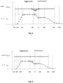
- the speed of a position-controlled spindle can be measured as a path speed profile in the same representation of a speed plan over the path parameter (or time) as in figure 4 shown.
- the cyclic position setpoints can then be sampled simultaneously by both profiles.
- each interpolated path point is assigned exactly one spindle orientation (i.e. an angle of the spindle relative to a zero point; a phase of the rotation of the spindle).
- spindle orientation i.e. an angle of the spindle relative to a zero point; a phase of the rotation of the spindle.
- An exact spindle orientation is assigned to at least one point on the path to supply the target parameters. According to the invention, this assignment takes place particularly advantageously in the NC program.
- the programming of such a synchronization condition leads to at least ( figure 5 ) once per adjacent milling path to a specified spindle orientation.
- the object of the method according to the invention is first of all to determine whether trajectory planning is possible while maintaining the dynamic limit values. In the event that trajectory planning is possible, two possible methods for establishing synchronicity are described below. In addition, a method is specified as to how advantageously the case can be dealt with when trajectory planning is not possible.
- the syntax extension provides a command G119 that expects a parameter S specifying an angular position of the spindle relative to a zero point (phase position).
- each setpoint position can be reached in two ways (rotating forwards or backwards). If the information about the direction of rotation is known, the position specification works up to 360° / TA . In other words, with an interpolation cycle of 1ms up to 60,000 rpm spindle speed.
- trajectory planning is possible, two methods can be used.
- the spindle performs a phase adjustment.
- the individual program lines are labeled N10, N20 and so on.
- the program line N70 contains the information that the spindle should assume an angle of 77° there.
- the created area in figure 5 is the velocity-time integral that corresponds to the required phase correction of the spindle position.
- the respective segment boundaries of the speed profiles are circled.
- the process is time-optimal without influencing the feed planning and has absolutely no negative influence on the total processing time of the part program.
- the position setpoint output to the spindle in the last cycle is known, as is the exact path parameter and thus also the duration (in path and time) until the synchronization point is reached.
- the angular position of the spindle at the synchronization point can be calculated if the spindle speed is not corrected.
- the amount of phase compensation required is then the difference between these two angular positions in the modulo circle. In the case of multi-edged tools, the required phase compensation can of course also be reduced to angular positions of 360°/number of cutting edges.
- a spindle speed profile can then be calculated that establishes the synchronization point exactly at the block limit. If the path feed (as in our example) is not constant during the phase correction of the spindle, it is important that the The spindle synchronization process ends exactly at the block boundary.
- the phase compensation takes place by lowering the feed level for a limited period of time, see FIG figure 6 .
- the procedure for temporarily lowering the feed level of the velocity profile is particularly efficient for high-speed spindles.
- the required amount and duration of the feed reduction are low because the spindle assumes practically any angular position in the range of milliseconds without varying the spindle speed.
- the procedure for calculating the synchronization process is as follows: the required phase correction amount is first determined as in the aforementioned method. After the calculation of the required phase correction up to the synchronization point, a modified piece of speed profile is calculated towards the synchronization point in such a way that the movement section requires exactly as much additional time (compared to the original planning) as the spindle needs to cover the required phase correction.
Landscapes
- Engineering & Computer Science (AREA)
- Physics & Mathematics (AREA)
- Geometry (AREA)
- Human Computer Interaction (AREA)
- Manufacturing & Machinery (AREA)
- General Physics & Mathematics (AREA)
- Automation & Control Theory (AREA)
- Mechanical Engineering (AREA)
- Numerical Control (AREA)
- Automatic Control Of Machine Tools (AREA)
- Milling Processes (AREA)
Priority Applications (1)
| Application Number | Priority Date | Filing Date | Title |
|---|---|---|---|
| HRP20231534TT HRP20231534T1 (hr) | 2018-07-09 | 2019-07-03 | Postupak glodanja |
Applications Claiming Priority (2)
| Application Number | Priority Date | Filing Date | Title |
|---|---|---|---|
| DE102018116553.6A DE102018116553B4 (de) | 2018-07-09 | 2018-07-09 | Fräsverfahren |
| PCT/EP2019/067869 WO2020011623A1 (de) | 2018-07-09 | 2019-07-03 | Fräsverfahren |
Publications (3)
| Publication Number | Publication Date |
|---|---|
| EP3821307A1 EP3821307A1 (de) | 2021-05-19 |
| EP3821307C0 EP3821307C0 (de) | 2023-08-30 |
| EP3821307B1 true EP3821307B1 (de) | 2023-08-30 |
Family
ID=67185015
Family Applications (1)
| Application Number | Title | Priority Date | Filing Date |
|---|---|---|---|
| EP19736669.3A Active EP3821307B1 (de) | 2018-07-09 | 2019-07-03 | Fräsverfahren |
Country Status (11)
| Country | Link |
|---|---|
| US (1) | US11507050B2 (https=) |
| EP (1) | EP3821307B1 (https=) |
| JP (1) | JP7065213B2 (https=) |
| KR (1) | KR102379284B1 (https=) |
| CN (1) | CN112513752B (https=) |
| DE (1) | DE102018116553B4 (https=) |
| ES (1) | ES2965775T3 (https=) |
| HR (1) | HRP20231534T1 (https=) |
| HU (1) | HUE064291T2 (https=) |
| PL (1) | PL3821307T3 (https=) |
| WO (1) | WO2020011623A1 (https=) |
Families Citing this family (2)
| Publication number | Priority date | Publication date | Assignee | Title |
|---|---|---|---|---|
| JP7648893B2 (ja) * | 2021-05-31 | 2025-03-19 | 株式会社ジャノメ | 経路教示データ作成装置及びその方法並びにプログラム |
| CN113798566B (zh) * | 2021-09-01 | 2024-03-29 | 上海东岩机械股份有限公司 | 一种螺旋铣削方法 |
Family Cites Families (12)
| Publication number | Priority date | Publication date | Assignee | Title |
|---|---|---|---|---|
| JPH09218706A (ja) * | 1996-02-14 | 1997-08-19 | Toyota Motor Corp | 加工方法とそのためのプログラム作成装置および加工装置 |
| JP3631593B2 (ja) * | 1997-08-20 | 2005-03-23 | トヨタ自動車株式会社 | カッタパス設定方法 |
| JP3954723B2 (ja) * | 1998-04-28 | 2007-08-08 | トヨタ自動車株式会社 | 加工方法、加工装置およびデータ作成装置 |
| SE531858C2 (sv) * | 2007-12-21 | 2009-08-25 | Sandvik Intellectual Property | Fräsverktyg för spånavskiljande bearbetning, samt skärkropp och grundkropp härför |
| DE102010060220B4 (de) * | 2010-10-28 | 2013-07-11 | Gebr. Heller Maschinenfabrik Gmbh | Verfahren zur Bearbeitung von Freiformflächen |
| US9507337B2 (en) * | 2011-10-27 | 2016-11-29 | Mitsubishi Electric Corporation | Numerical control device |
| CN103576610A (zh) * | 2012-08-03 | 2014-02-12 | 德马吉森精机株式会社 | 机床、加工方法、程序和nc数据生成装置 |
| CN103042434B (zh) * | 2012-12-08 | 2014-12-10 | 华中科技大学 | 超精密铣削加工表面形貌纹理控制方法 |
| JP5855715B1 (ja) | 2014-08-07 | 2016-02-09 | ファナック株式会社 | 工作機械 |
| JP2017001153A (ja) * | 2015-06-12 | 2017-01-05 | 東芝機械株式会社 | エンドミルを用いた加工システム及び加工方法 |
| US9776255B2 (en) * | 2015-10-01 | 2017-10-03 | Delcam Limited | System and method for machining blades, blisks and aerofoils |
| JP6740199B2 (ja) | 2017-10-30 | 2020-08-12 | ファナック株式会社 | 数値制御装置、cnc工作機械、数値制御方法及び数値制御用プログラム |
-
2018
- 2018-07-09 DE DE102018116553.6A patent/DE102018116553B4/de not_active Expired - Fee Related
-
2019
- 2019-07-03 JP JP2020569133A patent/JP7065213B2/ja not_active Expired - Fee Related
- 2019-07-03 HU HUE19736669A patent/HUE064291T2/hu unknown
- 2019-07-03 KR KR1020217000475A patent/KR102379284B1/ko not_active Expired - Fee Related
- 2019-07-03 EP EP19736669.3A patent/EP3821307B1/de active Active
- 2019-07-03 CN CN201980040339.5A patent/CN112513752B/zh active Active
- 2019-07-03 US US17/258,554 patent/US11507050B2/en active Active
- 2019-07-03 WO PCT/EP2019/067869 patent/WO2020011623A1/de not_active Ceased
- 2019-07-03 PL PL19736669.3T patent/PL3821307T3/pl unknown
- 2019-07-03 HR HRP20231534TT patent/HRP20231534T1/hr unknown
- 2019-07-03 ES ES19736669T patent/ES2965775T3/es active Active
Also Published As
| Publication number | Publication date |
|---|---|
| DE102018116553B4 (de) | 2020-11-05 |
| US11507050B2 (en) | 2022-11-22 |
| JP7065213B2 (ja) | 2022-05-11 |
| ES2965775T3 (es) | 2024-04-16 |
| KR102379284B1 (ko) | 2022-03-25 |
| HUE064291T2 (hu) | 2024-02-28 |
| JP2021524386A (ja) | 2021-09-13 |
| EP3821307C0 (de) | 2023-08-30 |
| WO2020011623A1 (de) | 2020-01-16 |
| KR20210029773A (ko) | 2021-03-16 |
| EP3821307A1 (de) | 2021-05-19 |
| HRP20231534T1 (hr) | 2024-03-01 |
| CN112513752A (zh) | 2021-03-16 |
| PL3821307T3 (pl) | 2024-03-04 |
| DE102018116553A1 (de) | 2020-01-09 |
| US20210149368A1 (en) | 2021-05-20 |
| CN112513752B (zh) | 2022-11-04 |
Similar Documents
| Publication | Publication Date | Title |
|---|---|---|
| DE102018002566B4 (de) | Steuervorrichtung für eine Oszillationschneiden durchführende Werkzeugmaschine | |
| EP3552744B1 (de) | Vorrichtung und verfahren zur anfasbearbeitung eines werkstücks | |
| EP2221693B1 (de) | Verfahren und Vorrichtung zum Erzeugen von Steuerdaten zum Steuern eines Werkzeugs an einer zumindest 5 Achsen umfassenden Werkzeugmaschine | |
| DE102015112577B4 (de) | Werkzeugmaschine | |
| EP2895290B1 (de) | Verfahren zum modifizieren der flanken eines zahns eines zahnrads mit hilfe eines werkzeugs | |
| EP3552743A1 (de) | Vorrichtung und verfahren zur anfasbearbeitung eines verzahnten werkstücks | |
| DE112014007112B4 (de) | Numerisch gesteuerte Vorrichtung | |
| EP2338640A1 (de) | Maschine zur Bearbeitung von optischen Werkstücken, insbesondere von Kunststoff-Brillengläsern | |
| DE102013112232B3 (de) | Verfahren zur Bearbeitung eines Rohteils mittels eines Werkzeuges | |
| EP1864739A1 (de) | Vorrichtung und Verfahren zur Weichbearbeitung von Kegelrädern und Verwendung der Vorrichtung | |
| EP3945381A1 (de) | Herstellung durch kegelsegmente bestimmbarer flächen mittels einer werkzeugmaschine | |
| DE102020117709A1 (de) | Zahnradbearbeitungsunterstützungsvorrichtung und Zahnradbearbeitungsvorrichtung | |
| DE69110583T2 (de) | Numerische steuerung. | |
| EP3821307B1 (de) | Fräsverfahren | |
| EP3332737A1 (de) | Verfahren zum erzeugen eines dentalrestaurationsteils sowie dentalbearbeitungsmaschine | |
| EP3341802B1 (de) | Verfahren zum erzeugen oder bearbeiten von verzahnungen an werkstücken | |
| DE3522977A1 (de) | Verfahren zum umfangsprofilieren eines werkstueckes | |
| EP1369759B1 (de) | Bahnsteuerungsverfahren einer numerisch gesteuerten Maschine | |
| DE19821557A1 (de) | Verfahren zur nichtlinearen Darstellung von Bahnkurven | |
| DE102017011602B4 (de) | Numerische Steuerung | |
| EP4246256A1 (de) | Werkstückbearbeitung mit optimierter spindeldrehzahl in abhängigkeit eines schnittpunktes | |
| WO2008125656A1 (de) | Verfahren und einrichtung zur bewegungsführung eines bewegbaren maschinenelements einer numerisch gesteuerten maschine | |
| DE2226547A1 (de) | Proportional Interpolator fur Mehr achsenmaschinen | |
| EP0563412B1 (de) | Werkzeugmaschine mit einer numerischen Steuerung zur Unterbrechung und Fortsetzung der Bearbeitung | |
| EP4066974A1 (de) | Verfahren zum erzeugen von verschränkungen an den zahnflanken eines innenverzahnten werkstücks |
Legal Events
| Date | Code | Title | Description |
|---|---|---|---|
| STAA | Information on the status of an ep patent application or granted ep patent |
Free format text: STATUS: UNKNOWN |
|
| STAA | Information on the status of an ep patent application or granted ep patent |
Free format text: STATUS: THE INTERNATIONAL PUBLICATION HAS BEEN MADE |
|
| PUAI | Public reference made under article 153(3) epc to a published international application that has entered the european phase |
Free format text: ORIGINAL CODE: 0009012 |
|
| STAA | Information on the status of an ep patent application or granted ep patent |
Free format text: STATUS: REQUEST FOR EXAMINATION WAS MADE |
|
| 17P | Request for examination filed |
Effective date: 20210202 |
|
| AK | Designated contracting states |
Kind code of ref document: A1 Designated state(s): AL AT BE BG CH CY CZ DE DK EE ES FI FR GB GR HR HU IE IS IT LI LT LU LV MC MK MT NL NO PL PT RO RS SE SI SK SM TR |
|
| DAV | Request for validation of the european patent (deleted) | ||
| DAX | Request for extension of the european patent (deleted) | ||
| GRAP | Despatch of communication of intention to grant a patent |
Free format text: ORIGINAL CODE: EPIDOSNIGR1 |
|
| STAA | Information on the status of an ep patent application or granted ep patent |
Free format text: STATUS: GRANT OF PATENT IS INTENDED |
|
| INTG | Intention to grant announced |
Effective date: 20230228 |
|
| GRAS | Grant fee paid |
Free format text: ORIGINAL CODE: EPIDOSNIGR3 |
|
| GRAA | (expected) grant |
Free format text: ORIGINAL CODE: 0009210 |
|
| STAA | Information on the status of an ep patent application or granted ep patent |
Free format text: STATUS: THE PATENT HAS BEEN GRANTED |
|
| AK | Designated contracting states |
Kind code of ref document: B1 Designated state(s): AL AT BE BG CH CY CZ DE DK EE ES FI FR GB GR HR HU IE IS IT LI LT LU LV MC MK MT NL NO PL PT RO RS SE SI SK SM TR |
|
| REG | Reference to a national code |
Ref country code: GB Ref legal event code: FG4D Free format text: NOT ENGLISH |
|
| REG | Reference to a national code |
Ref country code: CH Ref legal event code: EP |
|
| REG | Reference to a national code |
Ref country code: DE Ref legal event code: R096 Ref document number: 502019009163 Country of ref document: DE |
|
| REG | Reference to a national code |
Ref country code: IE Ref legal event code: FG4D Free format text: LANGUAGE OF EP DOCUMENT: GERMAN |
|
| U01 | Request for unitary effect filed |
Effective date: 20230927 |
|
| U07 | Unitary effect registered |
Designated state(s): AT BE BG DE DK EE FI FR IT LT LU LV MT NL PT SE SI Effective date: 20231108 |
|
| PG25 | Lapsed in a contracting state [announced via postgrant information from national office to epo] |
Ref country code: GR Free format text: LAPSE BECAUSE OF FAILURE TO SUBMIT A TRANSLATION OF THE DESCRIPTION OR TO PAY THE FEE WITHIN THE PRESCRIBED TIME-LIMIT Effective date: 20231201 |
|
| PG25 | Lapsed in a contracting state [announced via postgrant information from national office to epo] |
Ref country code: IS Free format text: LAPSE BECAUSE OF FAILURE TO SUBMIT A TRANSLATION OF THE DESCRIPTION OR TO PAY THE FEE WITHIN THE PRESCRIBED TIME-LIMIT Effective date: 20231230 |
|
| PG25 | Lapsed in a contracting state [announced via postgrant information from national office to epo] |
Ref country code: RS Free format text: LAPSE BECAUSE OF FAILURE TO SUBMIT A TRANSLATION OF THE DESCRIPTION OR TO PAY THE FEE WITHIN THE PRESCRIBED TIME-LIMIT Effective date: 20230830 Ref country code: NO Free format text: LAPSE BECAUSE OF FAILURE TO SUBMIT A TRANSLATION OF THE DESCRIPTION OR TO PAY THE FEE WITHIN THE PRESCRIBED TIME-LIMIT Effective date: 20231130 Ref country code: IS Free format text: LAPSE BECAUSE OF FAILURE TO SUBMIT A TRANSLATION OF THE DESCRIPTION OR TO PAY THE FEE WITHIN THE PRESCRIBED TIME-LIMIT Effective date: 20231230 Ref country code: GR Free format text: LAPSE BECAUSE OF FAILURE TO SUBMIT A TRANSLATION OF THE DESCRIPTION OR TO PAY THE FEE WITHIN THE PRESCRIBED TIME-LIMIT Effective date: 20231201 |
|
| REG | Reference to a national code |
Ref country code: SK Ref legal event code: T3 Ref document number: E 42925 Country of ref document: SK |
|
| REG | Reference to a national code |
Ref country code: HU Ref legal event code: AG4A Ref document number: E064291 Country of ref document: HU |
|
| REG | Reference to a national code |
Ref country code: HR Ref legal event code: T1PR Ref document number: P20231534 Country of ref document: HR |
|
| REG | Reference to a national code |
Ref country code: ES Ref legal event code: FG2A Ref document number: 2965775 Country of ref document: ES Kind code of ref document: T3 Effective date: 20240416 |
|
| PG25 | Lapsed in a contracting state [announced via postgrant information from national office to epo] |
Ref country code: SM Free format text: LAPSE BECAUSE OF FAILURE TO SUBMIT A TRANSLATION OF THE DESCRIPTION OR TO PAY THE FEE WITHIN THE PRESCRIBED TIME-LIMIT Effective date: 20230830 |
|
| REG | Reference to a national code |
Ref country code: DE Ref legal event code: R097 Ref document number: 502019009163 Country of ref document: DE |
|
| PLBE | No opposition filed within time limit |
Free format text: ORIGINAL CODE: 0009261 |
|
| STAA | Information on the status of an ep patent application or granted ep patent |
Free format text: STATUS: NO OPPOSITION FILED WITHIN TIME LIMIT |
|
| REG | Reference to a national code |
Ref country code: HR Ref legal event code: ODRP Ref document number: P20231534 Country of ref document: HR Payment date: 20240703 Year of fee payment: 6 |
|
| PGFP | Annual fee paid to national office [announced via postgrant information from national office to epo] |
Ref country code: SK Payment date: 20240701 Year of fee payment: 6 |
|
| 26N | No opposition filed |
Effective date: 20240603 |
|
| U20 | Renewal fee for the european patent with unitary effect paid |
Year of fee payment: 6 Effective date: 20240724 |
|
| PGFP | Annual fee paid to national office [announced via postgrant information from national office to epo] |
Ref country code: HR Payment date: 20240703 Year of fee payment: 6 Ref country code: IE Payment date: 20240719 Year of fee payment: 6 |
|
| PGFP | Annual fee paid to national office [announced via postgrant information from national office to epo] |
Ref country code: ES Payment date: 20240801 Year of fee payment: 6 Ref country code: CH Payment date: 20240801 Year of fee payment: 6 |
|
| PGFP | Annual fee paid to national office [announced via postgrant information from national office to epo] |
Ref country code: CZ Payment date: 20240702 Year of fee payment: 6 |
|
| PGFP | Annual fee paid to national office [announced via postgrant information from national office to epo] |
Ref country code: PL Payment date: 20240702 Year of fee payment: 6 |
|
| PGFP | Annual fee paid to national office [announced via postgrant information from national office to epo] |
Ref country code: HU Payment date: 20240703 Year of fee payment: 6 |
|
| PGFP | Annual fee paid to national office [announced via postgrant information from national office to epo] |
Ref country code: RO Payment date: 20240703 Year of fee payment: 6 |
|
| PG25 | Lapsed in a contracting state [announced via postgrant information from national office to epo] |
Ref country code: MC Free format text: LAPSE BECAUSE OF FAILURE TO SUBMIT A TRANSLATION OF THE DESCRIPTION OR TO PAY THE FEE WITHIN THE PRESCRIBED TIME-LIMIT Effective date: 20230830 |
|
| GBPC | Gb: european patent ceased through non-payment of renewal fee |
Effective date: 20240703 |
|
| PG25 | Lapsed in a contracting state [announced via postgrant information from national office to epo] |
Ref country code: GB Free format text: LAPSE BECAUSE OF NON-PAYMENT OF DUE FEES Effective date: 20240703 |
|
| PG25 | Lapsed in a contracting state [announced via postgrant information from national office to epo] |
Ref country code: CY Free format text: LAPSE BECAUSE OF FAILURE TO SUBMIT A TRANSLATION OF THE DESCRIPTION OR TO PAY THE FEE WITHIN THE PRESCRIBED TIME-LIMIT; INVALID AB INITIO Effective date: 20190703 |
|
| REG | Reference to a national code |
Ref country code: HR Ref legal event code: PBON Ref document number: P20231534 Country of ref document: HR Effective date: 20250703 |
|
| PG25 | Lapsed in a contracting state [announced via postgrant information from national office to epo] |
Ref country code: CZ Free format text: LAPSE BECAUSE OF NON-PAYMENT OF DUE FEES Effective date: 20250703 |
|
| REG | Reference to a national code |
Ref country code: SK Ref legal event code: MM4A Ref document number: E 42925 Country of ref document: SK Effective date: 20250703 |
|
| REG | Reference to a national code |
Ref country code: CH Ref legal event code: H13 Free format text: ST27 STATUS EVENT CODE: U-0-0-H10-H13 (AS PROVIDED BY THE NATIONAL OFFICE) Effective date: 20260224 |
|
| PG25 | Lapsed in a contracting state [announced via postgrant information from national office to epo] |
Ref country code: HU Free format text: LAPSE BECAUSE OF NON-PAYMENT OF DUE FEES Effective date: 20250704 |
|
| U90 | Renewal fees not paid: noting of loss of rights |
Free format text: RENEWAL FEE NOT PAID FOR YEAR 07 Effective date: 20260224 |
|
| PG25 | Lapsed in a contracting state [announced via postgrant information from national office to epo] |
Ref country code: HR Free format text: LAPSE BECAUSE OF NON-PAYMENT OF DUE FEES Effective date: 20250703 |
|
| PG25 | Lapsed in a contracting state [announced via postgrant information from national office to epo] |
Ref country code: RO Free format text: LAPSE BECAUSE OF NON-PAYMENT OF DUE FEES Effective date: 20250703 |
|
| PG25 | Lapsed in a contracting state [announced via postgrant information from national office to epo] |
Ref country code: CH Free format text: LAPSE BECAUSE OF NON-PAYMENT OF DUE FEES Effective date: 20250731 |
|
| PG25 | Lapsed in a contracting state [announced via postgrant information from national office to epo] |
Ref country code: SK Free format text: LAPSE BECAUSE OF NON-PAYMENT OF DUE FEES Effective date: 20250703 |