EP3819999A1 - Single-piece connector - Google Patents
Single-piece connector Download PDFInfo
- Publication number
- EP3819999A1 EP3819999A1 EP20020516.9A EP20020516A EP3819999A1 EP 3819999 A1 EP3819999 A1 EP 3819999A1 EP 20020516 A EP20020516 A EP 20020516A EP 3819999 A1 EP3819999 A1 EP 3819999A1
- Authority
- EP
- European Patent Office
- Prior art keywords
- built
- housing
- light
- connector
- light source
- Prior art date
- Legal status (The legal status is an assumption and is not a legal conclusion. Google has not performed a legal analysis and makes no representation as to the accuracy of the status listed.)
- Pending
Links
- 238000003780 insertion Methods 0.000 claims abstract description 22
- 230000037431 insertion Effects 0.000 claims abstract description 22
- 230000008878 coupling Effects 0.000 claims abstract description 20
- 238000010168 coupling process Methods 0.000 claims abstract description 20
- 238000005859 coupling reaction Methods 0.000 claims abstract description 20
- 230000003287 optical effect Effects 0.000 claims abstract description 7
- 230000000295 complement effect Effects 0.000 claims abstract description 6
- 238000000149 argon plasma sintering Methods 0.000 claims abstract description 4
- 239000003086 colorant Substances 0.000 claims description 11
- 239000000463 material Substances 0.000 claims description 6
- 230000000630 rising effect Effects 0.000 claims 1
- 239000004020 conductor Substances 0.000 abstract description 5
- 238000009434 installation Methods 0.000 description 8
- 230000005540 biological transmission Effects 0.000 description 2
- 230000007246 mechanism Effects 0.000 description 2
- 230000008054 signal transmission Effects 0.000 description 2
- 230000009471 action Effects 0.000 description 1
- 230000000712 assembly Effects 0.000 description 1
- 238000000429 assembly Methods 0.000 description 1
- 230000008901 benefit Effects 0.000 description 1
- 230000015572 biosynthetic process Effects 0.000 description 1
- 230000008859 change Effects 0.000 description 1
- 238000010276 construction Methods 0.000 description 1
- 238000005553 drilling Methods 0.000 description 1
- 230000003028 elevating effect Effects 0.000 description 1
- 239000011810 insulating material Substances 0.000 description 1
- 230000007257 malfunction Effects 0.000 description 1
- 239000002184 metal Substances 0.000 description 1
- 230000005405 multipole Effects 0.000 description 1
- BASFCYQUMIYNBI-UHFFFAOYSA-N platinum Chemical compound [Pt] BASFCYQUMIYNBI-UHFFFAOYSA-N 0.000 description 1
- 238000009420 retrofitting Methods 0.000 description 1
- 230000000007 visual effect Effects 0.000 description 1
Images


Classifications
-
- H—ELECTRICITY
- H01—ELECTRIC ELEMENTS
- H01R—ELECTRICALLY-CONDUCTIVE CONNECTIONS; STRUCTURAL ASSOCIATIONS OF A PLURALITY OF MUTUALLY-INSULATED ELECTRICAL CONNECTING ELEMENTS; COUPLING DEVICES; CURRENT COLLECTORS
- H01R13/00—Details of coupling devices of the kinds covered by groups H01R12/70 or H01R24/00 - H01R33/00
- H01R13/66—Structural association with built-in electrical component
- H01R13/717—Structural association with built-in electrical component with built-in light source
- H01R13/7172—Conduits for light transmission
-
- H—ELECTRICITY
- H01—ELECTRIC ELEMENTS
- H01R—ELECTRICALLY-CONDUCTIVE CONNECTIONS; STRUCTURAL ASSOCIATIONS OF A PLURALITY OF MUTUALLY-INSULATED ELECTRICAL CONNECTING ELEMENTS; COUPLING DEVICES; CURRENT COLLECTORS
- H01R13/00—Details of coupling devices of the kinds covered by groups H01R12/70 or H01R24/00 - H01R33/00
- H01R13/62—Means for facilitating engagement or disengagement of coupling parts or for holding them in engagement
- H01R13/627—Snap or like fastening
- H01R13/6271—Latching means integral with the housing
- H01R13/6272—Latching means integral with the housing comprising a single latching arm
-
- G—PHYSICS
- G02—OPTICS
- G02B—OPTICAL ELEMENTS, SYSTEMS OR APPARATUS
- G02B6/00—Light guides; Structural details of arrangements comprising light guides and other optical elements, e.g. couplings
- G02B6/24—Coupling light guides
- G02B6/36—Mechanical coupling means
- G02B6/38—Mechanical coupling means having fibre to fibre mating means
- G02B6/3807—Dismountable connectors, i.e. comprising plugs
- G02B6/381—Dismountable connectors, i.e. comprising plugs of the ferrule type, e.g. fibre ends embedded in ferrules, connecting a pair of fibres
- G02B6/3817—Dismountable connectors, i.e. comprising plugs of the ferrule type, e.g. fibre ends embedded in ferrules, connecting a pair of fibres containing optical and electrical conductors
-
- H—ELECTRICITY
- H01—ELECTRIC ELEMENTS
- H01R—ELECTRICALLY-CONDUCTIVE CONNECTIONS; STRUCTURAL ASSOCIATIONS OF A PLURALITY OF MUTUALLY-INSULATED ELECTRICAL CONNECTING ELEMENTS; COUPLING DEVICES; CURRENT COLLECTORS
- H01R12/00—Structural associations of a plurality of mutually-insulated electrical connecting elements, specially adapted for printed circuits, e.g. printed circuit boards [PCB], flat or ribbon cables, or like generally planar structures, e.g. terminal strips, terminal blocks; Coupling devices specially adapted for printed circuits, flat or ribbon cables, or like generally planar structures; Terminals specially adapted for contact with, or insertion into, printed circuits, flat or ribbon cables, or like generally planar structures
- H01R12/70—Coupling devices
- H01R12/71—Coupling devices for rigid printing circuits or like structures
- H01R12/712—Coupling devices for rigid printing circuits or like structures co-operating with the surface of the printed circuit or with a coupling device exclusively provided on the surface of the printed circuit
- H01R12/716—Coupling device provided on the PCB
-
- H—ELECTRICITY
- H01—ELECTRIC ELEMENTS
- H01R—ELECTRICALLY-CONDUCTIVE CONNECTIONS; STRUCTURAL ASSOCIATIONS OF A PLURALITY OF MUTUALLY-INSULATED ELECTRICAL CONNECTING ELEMENTS; COUPLING DEVICES; CURRENT COLLECTORS
- H01R13/00—Details of coupling devices of the kinds covered by groups H01R12/70 or H01R24/00 - H01R33/00
- H01R13/46—Bases; Cases
- H01R13/465—Identification means, e.g. labels, tags, markings
-
- H—ELECTRICITY
- H01—ELECTRIC ELEMENTS
- H01R—ELECTRICALLY-CONDUCTIVE CONNECTIONS; STRUCTURAL ASSOCIATIONS OF A PLURALITY OF MUTUALLY-INSULATED ELECTRICAL CONNECTING ELEMENTS; COUPLING DEVICES; CURRENT COLLECTORS
- H01R13/00—Details of coupling devices of the kinds covered by groups H01R12/70 or H01R24/00 - H01R33/00
- H01R13/46—Bases; Cases
- H01R13/502—Bases; Cases composed of different pieces
-
- H—ELECTRICITY
- H01—ELECTRIC ELEMENTS
- H01R—ELECTRICALLY-CONDUCTIVE CONNECTIONS; STRUCTURAL ASSOCIATIONS OF A PLURALITY OF MUTUALLY-INSULATED ELECTRICAL CONNECTING ELEMENTS; COUPLING DEVICES; CURRENT COLLECTORS
- H01R13/00—Details of coupling devices of the kinds covered by groups H01R12/70 or H01R24/00 - H01R33/00
- H01R13/62—Means for facilitating engagement or disengagement of coupling parts or for holding them in engagement
- H01R13/627—Snap or like fastening
-
- H—ELECTRICITY
- H01—ELECTRIC ELEMENTS
- H01R—ELECTRICALLY-CONDUCTIVE CONNECTIONS; STRUCTURAL ASSOCIATIONS OF A PLURALITY OF MUTUALLY-INSULATED ELECTRICAL CONNECTING ELEMENTS; COUPLING DEVICES; CURRENT COLLECTORS
- H01R13/00—Details of coupling devices of the kinds covered by groups H01R12/70 or H01R24/00 - H01R33/00
- H01R13/62—Means for facilitating engagement or disengagement of coupling parts or for holding them in engagement
- H01R13/639—Additional means for holding or locking coupling parts together, after engagement, e.g. separate keylock, retainer strap
-
- H—ELECTRICITY
- H01—ELECTRIC ELEMENTS
- H01R—ELECTRICALLY-CONDUCTIVE CONNECTIONS; STRUCTURAL ASSOCIATIONS OF A PLURALITY OF MUTUALLY-INSULATED ELECTRICAL CONNECTING ELEMENTS; COUPLING DEVICES; CURRENT COLLECTORS
- H01R13/00—Details of coupling devices of the kinds covered by groups H01R12/70 or H01R24/00 - H01R33/00
- H01R13/66—Structural association with built-in electrical component
- H01R13/665—Structural association with built-in electrical component with built-in electronic circuit
-
- H—ELECTRICITY
- H01—ELECTRIC ELEMENTS
- H01R—ELECTRICALLY-CONDUCTIVE CONNECTIONS; STRUCTURAL ASSOCIATIONS OF A PLURALITY OF MUTUALLY-INSULATED ELECTRICAL CONNECTING ELEMENTS; COUPLING DEVICES; CURRENT COLLECTORS
- H01R13/00—Details of coupling devices of the kinds covered by groups H01R12/70 or H01R24/00 - H01R33/00
- H01R13/66—Structural association with built-in electrical component
- H01R13/717—Structural association with built-in electrical component with built-in light source
- H01R13/7175—Light emitting diodes (LEDs)
-
- G—PHYSICS
- G02—OPTICS
- G02B—OPTICAL ELEMENTS, SYSTEMS OR APPARATUS
- G02B6/00—Light guides; Structural details of arrangements comprising light guides and other optical elements, e.g. couplings
- G02B6/24—Coupling light guides
- G02B6/36—Mechanical coupling means
- G02B6/38—Mechanical coupling means having fibre to fibre mating means
- G02B6/3807—Dismountable connectors, i.e. comprising plugs
- G02B6/3897—Connectors fixed to housings, casing, frames or circuit boards
-
- H—ELECTRICITY
- H01—ELECTRIC ELEMENTS
- H01R—ELECTRICALLY-CONDUCTIVE CONNECTIONS; STRUCTURAL ASSOCIATIONS OF A PLURALITY OF MUTUALLY-INSULATED ELECTRICAL CONNECTING ELEMENTS; COUPLING DEVICES; CURRENT COLLECTORS
- H01R12/00—Structural associations of a plurality of mutually-insulated electrical connecting elements, specially adapted for printed circuits, e.g. printed circuit boards [PCB], flat or ribbon cables, or like generally planar structures, e.g. terminal strips, terminal blocks; Coupling devices specially adapted for printed circuits, flat or ribbon cables, or like generally planar structures; Terminals specially adapted for contact with, or insertion into, printed circuits, flat or ribbon cables, or like generally planar structures
- H01R12/70—Coupling devices
- H01R12/71—Coupling devices for rigid printing circuits or like structures
- H01R12/72—Coupling devices for rigid printing circuits or like structures coupling with the edge of the rigid printed circuits or like structures
- H01R12/722—Coupling devices for rigid printing circuits or like structures coupling with the edge of the rigid printed circuits or like structures coupling devices mounted on the edge of the printed circuits
-
- H—ELECTRICITY
- H01—ELECTRIC ELEMENTS
- H01R—ELECTRICALLY-CONDUCTIVE CONNECTIONS; STRUCTURAL ASSOCIATIONS OF A PLURALITY OF MUTUALLY-INSULATED ELECTRICAL CONNECTING ELEMENTS; COUPLING DEVICES; CURRENT COLLECTORS
- H01R13/00—Details of coupling devices of the kinds covered by groups H01R12/70 or H01R24/00 - H01R33/00
- H01R13/62—Means for facilitating engagement or disengagement of coupling parts or for holding them in engagement
- H01R13/629—Additional means for facilitating engagement or disengagement of coupling parts, e.g. aligning or guiding means, levers, gas pressure electrical locking indicators, manufacturing tolerances
- H01R13/633—Additional means for facilitating engagement or disengagement of coupling parts, e.g. aligning or guiding means, levers, gas pressure electrical locking indicators, manufacturing tolerances for disengagement only
-
- H—ELECTRICITY
- H01—ELECTRIC ELEMENTS
- H01R—ELECTRICALLY-CONDUCTIVE CONNECTIONS; STRUCTURAL ASSOCIATIONS OF A PLURALITY OF MUTUALLY-INSULATED ELECTRICAL CONNECTING ELEMENTS; COUPLING DEVICES; CURRENT COLLECTORS
- H01R24/00—Two-part coupling devices, or either of their cooperating parts, characterised by their overall structure
- H01R24/60—Contacts spaced along planar side wall transverse to longitudinal axis of engagement
- H01R24/62—Sliding engagements with one side only, e.g. modular jack coupling devices
- H01R24/64—Sliding engagements with one side only, e.g. modular jack coupling devices for high frequency, e.g. RJ 45
Definitions
- the invention relates to a built-in connector, with a housing with an insertion opening for a complementary cable connector, with a contact carrier inserted or formed in the housing, with electrical or optical contacts fixed in the contact carrier, and with a front panel which is arranged on the front of the housing , and a built-in connector arrangement, comprising such a built-in connector and a circuit board connected thereto.
- Such built-in connectors also referred to as built-in sockets or chassis sockets, are intended for installation in control panels, switch cabinets or the walls of device housings and are designed for connection to standard printed circuit boards or boards that are used in the entertainment industry. They are available in a wide variety of designs, i.e. with different numbers and designs of contacts, as well as with different grounding and connection variants and as male and female connectors. They are used as electrical connectors for the transmission of electrical energy or analog or digital data, as well as optical connectors for light guides and optical cables.
- Cable plugs are known with a light source supplied by the utility line, which illuminates a light ring with three windows offset by 120 degrees. Furthermore, in the US 6690804 B2 a system is known in which microphones and their cables are provided with controllable LEDs in order to quickly distinguish the individual devices visually by means of different colors. The energy is supplied via the phantom power source of the sound mixing system. Furthermore, chassis sockets with a ring surrounding the plug-in opening made up of several LEDs built into the built-in socket itself or a narrow ring illuminated by built-in LEDs for displaying the connection status are also known. An energy supply with the risk of interference with the signal transmission is thus also integrated into the socket itself here.
- the CN 208849186 U , NL 1032887 A1 , EP 2904982 A1 and DE 102010021587 A1 show built-in or surface-mounted sockets of various types, which contain light sources and light-conducting elements.
- the CN 208849186 U a charging plug for the Installation in vehicles.
- the plug has a flange with mounting holes and a cover plate covering this flange with an annular transparent area.
- a light-conducting element is embedded in the flange and is completely enclosed below the transparent cover plate.
- the light-guiding element is illuminated by two LEDs that are attached to a circuit board. To do this, the light is coupled in via the two opposite end faces.
- the charging status of the vehicle can be displayed by changing the color.
- NL 1032887 A1 discloses a surface mount socket for trailers for motor vehicles.
- the socket has two mounting holes.
- Elongated contacts protrude parallel to one another from a disk-shaped contact carrier, a guide cylinder made of light-conducting material being pushed onto the contacts.
- a hollow cylindrical bushing which surrounds the cylinder with the contacts in a ring shape while forming an annular gap, also made of light-conducting material.
- the guide cylinder and the socket are illuminated separately by at least one LED each.
- the enveloping housing has a spring-loaded cover which, when closed, covers the entire plug-in opening, and which has a fork-shaped recess with which an inserted plug can be fixed / locked, with a large part of the plug-in opening being covered again.
- the EP 2904982 A1 describes a socket insert for an electrosurgical device.
- Transparent frames are provided around the actual plug sockets or their insertion openings, which can be used, for example, as an operating status indicator, with light from a light source being coupled into the transparent frame via an insert housing designed as a light guide.
- the light source is preferably formed by a backlighting circuit board with light-emitting diodes in the device housing.
- DE 102010021587 A1 finally discloses a multi-pole charging socket for electric vehicles with a housing with a locking function, which has a flange-like edge.
- Parts of the housing can consist of a translucent, possibly also colored, material, with light sources being arranged in the housing.
- the object of the present invention was to overcome the disadvantages of the prior art and to provide a built-in connector or an arrangement with such a connector, which have a status display that can be easily recognized at any time and as unhindered as possible, especially in dark surroundings, with which there is no risk of malfunction or There is an influence on the useful signals and which can be produced with a simple structure without great effort and preferably also allow retrofitting of existing built-in connectors with a similar structure.
- the device according to the invention is characterized in that the front plate consists of a light-scattering or light-conducting material, has at least one coupling surface for light from an external light source and has a circumferential and forward-rising web that runs along at least part of the circumference of the insertion opening and forms the front end and the outer delimitation of the insertion opening.
- the front plate is preferably made of a colorless material. This means that different colors and also changing colors can be displayed with just one front panel by using light sources with different colors.
- a preferred embodiment of a built-in connector according to the invention provides that the housing and the front panel have corresponding assembly sections which protrude radially from the axis of the insertion opening and are provided with at least one assembly hole to enable installation behind the walls of devices, switchboards or the like.
- the coupling-in surface is preferably arranged on at least one of the mounting sections of the front panel. This makes it possible to design the coupling surface very freely and optimally for the coupling of the light source used in each case.
- a preferred variant provides that the coupling-in surface is oriented radially, provision preferably being made for the cross-section of the mounting section to enlarge towards the coupling-in surface. This allows the simple coupling of a light source arranged adjacent to the front plate and the optimal light conduction with concentration of the coupled light on the cross section of the part of the front plate that is to be illuminated in any case.
- Another optional embodiment of the invention provides a built-in connector in which the housing has a recess for a locking arrangement for the cable plug, the locking arrangement comprising an unlocking element protruding forward from the housing, and the front panel having a cutout for the unlocking element to pass through .
- a solution to the problem set out at the beginning is also possible by means of a built-in connector arrangement which comprises a built-in connector according to one of the preceding paragraphs and a circuit board connected to it.
- This arrangement is further characterized in that a light source and its control and energy supply are provided on the board and at least the light source is arranged directly adjacent to the coupling point. This means that the light supply remains isolated from the useful contacts in terms of potential and cannot influence the signal transmission.
- the light source is preferably designed or controllable to emit light of at least two different colors in order to distinguish the individual sockets and / or to display the respective connection status.
- An alternative embodiment of the invention then provides that the control of the light source is coupled to a circuit for determining different states of the arrangement and the control is designed such that different states are characterized by the emission of light of different colors.
- the light source preferably has LEDs or OLEDs as lighting means.
- electrical built-in connector which is designed in a form as an RJ45 socket for data transmission.
- all types of power and data plugs can be designed according to the features according to the invention, for example according to the XLR standard, in male or female design, etc.
- optical built-in plug connectors can also have essentially the same structure.
- a contact carrier 3 is inserted in a housing 1 with an insertion opening 2 for a complementary cable connector.
- the contacts 4 fixed in the contact carrier 3 protrude from the rear of the housing 1.
- the housing 1 is - as in Fig. 2 can be seen better - made up of two concentrically arranged housing parts, an outer housing part 5 and an inner housing part 6, which are spaced apart by an annular gap 7, this annular gap 7 forming an annular insertion opening for a socket-shaped plug extension of a complementary cable connector.
- An annular base 8 connects the two housing parts 5, 6 to one another at the end of the housing 1 opposite the insertion opening 2.
- the contact carrier 3 can preferably be an integral part or section of the housing 1, but it can also be designed as a separate part and inserted into a corresponding receptacle in the housing 1.
- this receptacle is the inner housing part 6 into which the contact carrier 3 is inserted.
- the housing 1 is typically made of metal and the contact carrier 3 is made of insulating material, preferably plastic.
- the contact carrier 3 is preferably provided in one piece with the housing 1 as its central section.
- a front plate 9 is arranged on the front side of the housing 1 and surrounds the front section of the contact carrier 3.
- the front plate 9, which preferably rests on the front side of the housing 1 and / or covers at least a substantial part, has a circumferential and forward section elevating web 10, which runs along at least a part, preferably the largest part, of the circumference of the insertion opening 2 and thereby forms the front end and the outer boundary of the insertion opening 2.
- the built-in connector arrangement shown further comprises a locking mechanism for the inserted complementary connector in order to prevent it from being unintentionally pulled off and thus the plug connection from being released.
- this mechanism has an unlocking element 11 which protrudes forward through recesses 19 in the housing 1 or recesses in the front panel 9, in particular through cutouts 12 in the web 10 on the outside of the insertion opening 2.
- the unlocking element 11 does not cover the annular gap 7 of the insertion opening and the area of the insertion opening and the contact carrier 3 enclosed by it, so that the front plate 9 or at least the web 10 thereof is visible at all times.
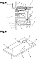
- Fig. 1 Finally, the printed circuit board or circuit board 13 is shown, here arranged horizontally, the housing 1 and the contact 4 then being provided with angled end pieces.
- the individually shown front panel is made of a light-scattering or light-guiding material. It has at least one coupling surface 14 for light from an external light source 22.
- two coupling surfaces 14 are preferably provided on both sides of the housing 1 immediately adjacent to the circuit board 13.
- these coupling-in surfaces 14 are oriented tangentially, ie their surface normal runs tangentially to the insertion opening 2.
- a radial arrangement of the coupling-in surfaces 14 is also very useful in order to couple light into the front plate 9, which is preferred for use with light sources 22 of any color, even from colorless Material is made.
- Other variants of the orientation of the coupling surfaces 14 are also possible.
- the coupling surfaces 14 can be oriented towards the rear and preferably lie in a plane perpendicular to the longitudinal axis of the built-in connector in order to be supplied with light from a light source 22 vertically attached to the rear of the housing 1 printed circuit board 13.
- the housing 1 Since the built-in connector assemblies according to the invention are intended for installation in devices or switch cabinets, switchboards or the like, at least the housing 1 has mounting sections 15 along the circumference in which mounting bores 16 are machined in order to facilitate the arrangement on the wall 21 of the device or the control panel od. Like. To attach (as exemplified in the longitudinal section of the Fig. 5 you can see).
- Fig. 5 a preferred embodiment of the built-in connector is shown, which is designed for installation behind the wall of switchboards, switch cabinets or on the back of the walls of device housings.
- the front plate 9 rests against the rear of the respective wall, the web 10 preferably having a height such that it ends at least at the level of the outside of the wall of the switchboard, switch cabinet or device housing or preferably even slightly above the outside the wall survives.
- the web 10 preferably has a height that it ends at least at the level of the outside of the cover plate or the flange or preferably even protrudes somewhat beyond its front surface.
- the cover plate or the flange then preferably has recesses which are aligned with the recesses 19 and through which the unlocking element 11 is passed.
- the built-in connector according to the invention could also be designed for installation from the front, with a front cover plate or a flange also preferably being provided.
- a front cover plate or a flange also preferably being provided.
- Mounting sections 17 with mounting bores 18 are preferably also provided on the front panel 9 at corresponding points.
- the arrangement of the coupling surfaces 14 on at least one of the mounting sections 17 of the front plate 9 is particularly preferred here.
- a section 20 which increases in cross-section to the coupling surface 14 is preferably provided between the front plate 9, ie the areas to be shown illuminated, and the coupling surfaces 14.
- the section 20 can be designed in the shape of a wedge, pyramid, cone or in a similar manner.
- pins 26 are furthermore preferably arranged and project perpendicularly and parallel to the longitudinal axis of the housing 1 towards the latter.
- the light source 22 for the light to be coupled into the front plate 9 via the coupling surfaces 14 is preferably mounted on the printed circuit board or circuit board 13.
- the actual lighting means preferably LEDs or OLEDs, is preferably arranged directly adjacent to the coupling surface 14.
- other types of arrangement of light sources 22 are possible, for example the "flying" one "Arrangement of wired light sources 22, preferably LEDs or OLEDs.
- the light source 22 is preferably designed or controllable for the emission of light of at least two different colors, for which purpose, for example, several illuminants in different colors can be used.
- the controller 23 of the light source 22 can at most be coupled to a circuit 27 for determining different states of the built-in connector arrangement and designed in such a way that different states are indicated by the emission of light of different colors.
- the assembly points 25 on the circuit board 13 for the contacts 4 are also shown.
- the front panel 9 can - with the exception of the coupling surfaces 14 and sections 20 with changing cross-sections that are not essential for compatibility - be designed in the same way as the commonly used front panels, so that existing built-in connectors can also be retrofitted at a later date, together with the Attachment of the light sources 22 and their control 23 on the already existing circuit boards 13.
- connection status can also be achieved for existing, retrofitted built-in connector arrangements of the arrangements according to the invention, which is common to all arrangements. It is also possible to visualize different diagnostic messages using even more colors.
Landscapes
- Physics & Mathematics (AREA)
- Engineering & Computer Science (AREA)
- Microelectronics & Electronic Packaging (AREA)
- Optics & Photonics (AREA)
- General Physics & Mathematics (AREA)
- Details Of Connecting Devices For Male And Female Coupling (AREA)
- Connector Housings Or Holding Contact Members (AREA)
- Light Guides In General And Applications Therefor (AREA)
Abstract
Die Erfindung betrifft einen Einbausteckverbinder. Er umfasst ein Gehäuse (1) mit einer Einstecköffnung (2) für einen komplementären Kabelsteckverbinder, einen in das Gehäuse (1) eingesetzten oder darin ausgebildeten Kontaktträger (3), im Kontaktträger (3) fixierte elektrische oder optische Kontakte (4), und eine Frontplatte (9), die an der Vorderseite des Gehäuses (1) angeordnet ist und mit einem zumindest über einen Teil des Umfangs der Einstecköffnung (2) umlaufenden ringförmigen Steg (3) das vordere Ende und die äussere Begrenzung der Einstecköffnung (2) bildet. Diese Frontplatte (9) besteht aus einem lichtstreuenden oder lichtleitenden Material und weist zumindest eine Einkoppelfläche (14) für Licht aus einer externen Lichtquelle (22) auf.The invention relates to a built-in connector. It comprises a housing (1) with an insertion opening (2) for a complementary cable connector, a contact carrier (3) inserted or formed in the housing (1), electrical or optical contacts (4) fixed in the contact carrier (3), and a Front plate (9) which is arranged on the front of the housing (1) and forms the front end and the outer delimitation of the insertion opening (2) with an annular web (3) running around at least part of the circumference of the insertion opening (2). This front plate (9) consists of a light-scattering or light-conducting material and has at least one coupling surface (14) for light from an external light source (22).
Description
Die Erfindung betrifft einen Einbausteckverbinder, mit einem Gehäuse mit einer Einstecköffnung für einen komplementären Kabelsteckverbinder, mit einem in das Gehäuse eingesetzten oder darin ausgebildeten Kontaktträger, mit im Kontaktträger fixierten elektrischen oder optischen Kontakten, und mit einer Frontplatte, die an der Vorderseite des Gehäuses angeordnet ist, sowie eine Einbausteckverbinder-Anordnung, umfassend einen derartigen Einbausteckverbinder und eine damit verbundene Platine.The invention relates to a built-in connector, with a housing with an insertion opening for a complementary cable connector, with a contact carrier inserted or formed in the housing, with electrical or optical contacts fixed in the contact carrier, and with a front panel which is arranged on the front of the housing , and a built-in connector arrangement, comprising such a built-in connector and a circuit board connected thereto.
Derartige Einbausteckverbinder, auch Einbaubuchsen oder Chassisbuchsen bezeichnet, sind zum Einbau in Schalttafeln, Schaltschränken oder auch den Wandungen von Gerätegehäusen vorgesehen und zur Verbindung mit Standard-Leiterplatten bzw. Platinen ausgelegt, die in der Unterhaltungsindustrie Verwendung finden. Sie sind in verschiedensten Ausführungsformen, d.h. mit unterschiedlicher Anzahl und Ausführung der Kontakte, sowie mit verschiedenen Erdungs- und Anschlussvarianten und als Male- und Female-Stecker verfügbar. Sie kommen als elektrische Steckverbinder für die Übertragung von elektrischer Energie oder analoger bzw. digitaler Daten, als auch als optische Steckverbinder für Lichtleiter und optische Kabel zum Einsatz.Such built-in connectors, also referred to as built-in sockets or chassis sockets, are intended for installation in control panels, switch cabinets or the walls of device housings and are designed for connection to standard printed circuit boards or boards that are used in the entertainment industry. They are available in a wide variety of designs, i.e. with different numbers and designs of contacts, as well as with different grounding and connection variants and as male and female connectors. They are used as electrical connectors for the transmission of electrical energy or analog or digital data, as well as optical connectors for light guides and optical cables.
Bekannt sind Kabelstecker mit einem von der Nutzleitung versorgten Leuchtmittel, das einen Leuchtring mit drei um jeweils 120 Grad versetzten Fenstern beleuchtet. Weiters ist in der
Die
Die
Aufgabe der vorliegenden Erfindung war es, die Nachteile des Standes der Technik zu überwinden und einen Einbausteckverbinder bzw. eine Anordnung mit einem derartigen Verbinder anzugeben, welche eine insbesondere in dunklen Umgebungen leicht und jederzeit möglichst ungehindert erkennbare Zustandsanzeige aufweisen, bei welchen keine Gefahr einer Störung oder Beeinflussung der Nutzsignale besteht und die durch einfachen Aufbau ohne grossen Aufwand hergestellt werden können und vorzugsweise auch die Nachrüstung bei bestehenden Einbausteckverbindern mit ähnlichem Aufbau gestatten.The object of the present invention was to overcome the disadvantages of the prior art and to provide a built-in connector or an arrangement with such a connector, which have a status display that can be easily recognized at any time and as unhindered as possible, especially in dark surroundings, with which there is no risk of malfunction or There is an influence on the useful signals and which can be produced with a simple structure without great effort and preferably also allow retrofitting of existing built-in connectors with a similar structure.
Diese Aufgabe wird durch eine Vorrichtung gemäss den Ansprüchen gelöst.This object is achieved by a device according to the claims.
Die erfindungsgemässe Vorrichtung ist dazu dadurch gekennzeichnet, dass die Frontplatte aus einem lichtstreuenden oder lichtleitenden Material besteht, zumindest eine Einkoppelfläche für Licht aus einer externen Lichtquelle aufweist und einen umlaufenden und sich nach vorne erhebenden Steg aufweist, der entlang zumindest eines Teils des Umfanges der Einstecköffnung verläuft und das vordere Ende und die äussere Begrenzung der Einstecköffnung bildet. Damit ist die optimale Versorgung und Verteilung des eingekoppelten Lichts sichergestellt und jederzeit die optimale Erkennbarkeit des sichtbaren Abschnittes der Frontplatte gewährleistet, wobei aber die Lichtquelle, deren Energieversorgung und Ansteuerung getrennt vom Einbausteckverbinder selbst und dessen Nutzkontakten ist, so dass die Gefahr der Beeinflussung der Nutzsignale durch die Beleuchtungsanordnung minimiert ist.The device according to the invention is characterized in that the front plate consists of a light-scattering or light-conducting material, has at least one coupling surface for light from an external light source and has a circumferential and forward-rising web that runs along at least part of the circumference of the insertion opening and forms the front end and the outer delimitation of the insertion opening. This ensures the optimal supply and distribution of the coupled light and ensures that the visible section of the front panel is always optimally recognizable, but the light source, its power supply and control are separate from the built-in connector itself and its useful contacts, so that there is a risk of the useful signals being influenced by the lighting arrangement is minimized.
Bevorzugt besteht die Frontplatte aus farblosem Material. Damit können mit nur einer Frontplatte durch Verwendung von Lichtquellen mit unterschiedlicher Färbung unterschiedliche Farben und auch wechselnde Farben dargestellt werden.The front plate is preferably made of a colorless material. This means that different colors and also changing colors can be displayed with just one front panel by using light sources with different colors.
Eine bevorzugte Ausführungsform eines erfindungsgemässen Einbausteckverbinders sieht zur Ermöglichung des Einbaus hinter die Wände von Geräten, Schalttafeln od. dgl. vor, dass das Gehäuse und die Frontplatte korrespondierende Montageabschnitte aufweisen, die zur Achse der Einstecköffnung radial auskragen und mit zumindest einer Montagebohrung versehen sind.A preferred embodiment of a built-in connector according to the invention provides that the housing and the front panel have corresponding assembly sections which protrude radially from the axis of the insertion opening and are provided with at least one assembly hole to enable installation behind the walls of devices, switchboards or the like.
Bei einem derartigen Einbausteckverbinder ist vorzugsweise die Einkoppelfläche an zumindest einem der Montageabschnitte der Frontplatte angeordnet. Damit ist es möglich, die Einkoppelfläche sehr frei und optimal auf die Einkopplung der jeweils verwendeten Lichtquelle zu gestalten.In the case of a built-in connector of this type, the coupling-in surface is preferably arranged on at least one of the mounting sections of the front panel. This makes it possible to design the coupling surface very freely and optimally for the coupling of the light source used in each case.
Weiters sieht eine bevorzugte Variante dabei vor, dass die Einkoppelfläche radial orientiert ist, wobei vorzugsweise vorgesehen ist, dass sich der Querschnitt des Montageabschnitts zur Einkoppelfläche hin vergrössert. Dies gestattet die einfache Einkopplung einer benachbart der Frontplatte angeordneten Lichtquelle und die optimale Lichtleitung mit Konzentration des eingekoppelten Lichtes auf den Querschnitt des jedenfalls zu beleuchtenden Teils der Frontplatte.Furthermore, a preferred variant provides that the coupling-in surface is oriented radially, provision preferably being made for the cross-section of the mounting section to enlarge towards the coupling-in surface. This allows the simple coupling of a light source arranged adjacent to the front plate and the optimal light conduction with concentration of the coupled light on the cross section of the part of the front plate that is to be illuminated in any case.
Eine weitere optionale Ausführungsform der Erfindung sieht einen Einbausteckverbinder vor, bei welchem im Gehäuse eine Ausnehmung für eine Verriegelungsanordnung für den Kabelstecker ausgearbeitet ist, wobei die Verriegelungsanordnung ein nach vorne aus dem Gehäuse ragendes Entriegelungselement umfasst, und wobei die Frontplatte einen Ausschnitt zur Durchführung des Entriegelungselementes aufweist.Another optional embodiment of the invention provides a built-in connector in which the housing has a recess for a locking arrangement for the cable plug, the locking arrangement comprising an unlocking element protruding forward from the housing, and the front panel having a cutout for the unlocking element to pass through .
Eine Lösung der eingangs gestellten Aufgabe ist auch durch eine Einbausteckverbinder-Anordnung möglich, die einen Einbausteckverbinder gemäss einem der vorhergehenden Absätze sowie eine damit verbundene Platine umfasst. Diese Anordnung ist weiters dadurch gekennzeichnet, dass auf der Platine eine Lichtquelle und deren Steuerung und Energieversorgung vorgesehen sind und zumindest die Lichtquelle unmittelbar benachbart der Einkoppelstelle angeordnet ist. Damit bleibt die Lichtversorgung potentialmässig getrennt von den Nutzkontakten und kann die Signalübertragung nicht beeinflussen.A solution to the problem set out at the beginning is also possible by means of a built-in connector arrangement which comprises a built-in connector according to one of the preceding paragraphs and a circuit board connected to it. This arrangement is further characterized in that a light source and its control and energy supply are provided on the board and at least the light source is arranged directly adjacent to the coupling point. This means that the light supply remains isolated from the useful contacts in terms of potential and cannot influence the signal transmission.
Vorzugsweise ist die Lichtquelle zur Emission von Licht zumindest zweier unterschiedlicher Farben ausgestaltet bzw. ansteuerbar, um die einzelnen Buchsen zu unterscheiden und/oder zur Anzeige des jeweiligen Verbindungsstatus.The light source is preferably designed or controllable to emit light of at least two different colors in order to distinguish the individual sockets and / or to display the respective connection status.
Eine alternative Ausführungsform der Erfindung sieht dann vor, dass die Steuerung der Lichtquelle mit einer Schaltung zur Feststellung unterschiedlicher Zustände der Anordnung gekoppelt ist und die Steuerung derart ausgelegt ist, dass unterschiedliche Zustände durch die Emission von Licht unterschiedlicher Farbe gekennzeichnet ist.An alternative embodiment of the invention then provides that the control of the light source is coupled to a circuit for determining different states of the arrangement and the control is designed such that different states are characterized by the emission of light of different colors.
Bevorzugt weist die Lichtquelle als Leuchtmittel LEDs oder OLEDs auf.The light source preferably has LEDs or OLEDs as lighting means.
Zum besseren Verständnis der Erfindung wird diese anhand der nachfolgenden Figuren näher erläutert.For a better understanding of the invention, it is explained in more detail with reference to the following figures.
Es zeigen jeweils in stark vereinfachter, schematischer Darstellung:
- Fig. 1
- eine Einbausteckverbinder-Anordnung in Form einer RJ45-Chassisbuchse in perspektivischer Darstellung von vorne;
- Fig. 2
- das Gehäuse des Einbausteckverbinders der Anordnung der
Fig. 1 mit eingesetzten Kontakten in perspektivischer Darstellung von vorne; - Fig. 3
- die erfindungsgemäss gestaltete Frontplatte des Einbausteckverbinders der Anordnung der
Fig. 1 in perspektivischer Ansicht von vorne; - Fig. 4
- die erfindungsgemäss gestaltete Frontplatte des Einbausteckverbinders der Anordnung der
Fig. 1 in perspektivischer Ansicht von hinten; - Fig. 5
- einen Längsschnitt durch die Einbausteckverbinder-Anordnung der
Fig. 1 , eingesetzt in die Wand eines Gerätes od. dgl., und - Fig. 6
- eine perspektivische Ansicht von oben einer Platine für die Einbausteckverbinder-Anordnung der
Fig. 1 .
- Fig. 1
- a built-in connector arrangement in the form of an RJ45 chassis socket in a perspective view from the front;
- Fig. 2
- the housing of the chassis connector of the arrangement of the
Fig. 1 with inserted contacts in a perspective view from the front; - Fig. 3
- the front panel of the built-in connector, designed according to the invention, of the arrangement of
Fig. 1 in perspective view from the front; - Fig. 4
- the front panel of the built-in connector, designed according to the invention, of the arrangement of
Fig. 1 in a perspective view from behind; - Fig. 5
- a longitudinal section through the built-in connector assembly of
Fig. 1 , used in the wall of a device or the like., And - Fig. 6
- a perspective view from above of a circuit board for the built-in connector arrangement of FIG
Fig. 1 .
Einführend sei festgehalten, dass in den unterschiedlich beschriebenen Ausführungsformen gleiche Teile mit gleichen Bezugszeichen bzw. gleichen Bauteilbezeichnungen versehen werden, wobei die in der gesamten Beschreibung enthaltenen Offenbarungen sinngemäss auf gleiche Teile mit gleichen Bezugszeichen bzw. gleichen Bauteilbezeichnungen übertragen werden können. Auch sind die in der Beschreibung gewählten Lageangaben, wie z.B. oben, unten, seitlich usw. auf die unmittelbar beschriebene sowie dargestellte Figur bezogen und sind diese Lageangaben bei einer Lageänderung sinngemäss auf die neue Lage zu übertragen.By way of introduction, it should be noted that in the differently described embodiments, the same parts are provided with the same reference symbols or the same component designations, whereby the disclosures contained in the entire description can be transferred accordingly to the same parts with the same reference symbols or the same component names. The position details chosen in the description, such as top, bottom, side, etc., also relate to the figure immediately described and shown and these position details are to be transferred to the new position in the event of a change in position.
Die Erfindung wird nachfolgend anhand eines in
In einem Gehäuse 1 mit einer Einstecköffnung 2 für einen komplementären Kabelsteckverbinder ist ein Kontaktträger 3 eingesetzt. Die im Kontaktträger 3 fixierten Kontakte 4 ragen auf der Hinterseite des Gehäuses 1 heraus. Das Gehäuse 1 ist - wie in
An der Vorderseite des Gehäuses 1 ist eine Frontplatte 9 angeordnet und umgibt den vorderen Abschnitt des Kontaktträgers 3. Die Frontplatte 9, die vorzugsweise auf der Vorderseite des Gehäuses 1 aufliegt und/oder zumindest zu einem wesentlichen Teil abdeckt, weist einen umlaufenden und sich nach vorne erhebenden Steg 10 auf, der entlang zumindest eines Teils, vorzugsweise des grössten Teils, des Umfanges der Einstecköffnung 2 verläuft und dabei das vordere Ende und die äussere Begrenzung der Einstecköffnung 2 bildet.A
Die in
In
Die in den
Da die erfindungsgemässen Einbausteckverbinder-Anordnungen zum Einbau in Geräte oder Schaltschränke, Schalttafeln od. dgl. vorgesehen sind, weist zumindest das Gehäuse 1 entlang des Umfanges Montageabschnitte 15 auf, in welchen Montagebohrungen 16 ausgearbeitet sind, um die Anordnung an der Wand 21 des Gerätes oder der Schalttafel od. dgl. zu befestigen (wie dies beispielhaft im Längsschnitt der
In
Der erfindungsgemässe Einbausteckverbinder könnte auch für den Einbau von vorne her konstruiert, wobei bevorzugt ebenfalls eine vordere Abdeckplatte bzw. ein Flansch vorgesehen ist. Für die Ausbildung der Frontplatte 9, des Steges 10 und der weiteren Bauelemente sind die gleichen Merkmale wie im vorigen Absatz erläutert vorgesehen.The built-in connector according to the invention could also be designed for installation from the front, with a front cover plate or a flange also preferably being provided. For the formation of the
Bevorzugt ist sind auch an der Frontplatte 9 an korrespondierenden Stellen Montageabschnitte 17 mit Montagebohrungen 18 vorhanden. Hier ist besonders bevorzugt die Anordnung der Einkoppelflächen 14 an zumindest einem der Montageabschnitte 17 der Frontplatte 9. Wie insbesondere in
Auf der dem Gehäuse 1 zugewandten Rückseite der Frontplatte 9 sind weiters bevorzugt noch Zapfen 26 angeordnet und ragen senkrecht und parallel zur Längsachse des Gehäuses 1 auf dieses zu. Sie greifen, wenn die Frontplatte 9 am Gehäuse 1 zum Anliegen aufgesteckt wird, in Bohrungen 27 an der Aussenseite des Gehäuses 1, vorzugsweise des äusseren Gehäuseteils 5, ein und sorgen für die korrekte Positionierung von Gehäuse 1 und Frontplatte 9 relativ zueinander. Weiters sind diese beiden Bauteile dann für die Handhabung und speziell für den Einbau in ein Gerät, eine Schalttafel, einen Schaltschrank od. dgl. gekoppelt und als ein gemeinsamer Teil handhabbar, was den Einbau wesentlich vereinfacht.On the rear side of the
Die Lichtquelle 22 für das in die Frontplatte 9 über die Einkoppelflächen 14 einzukoppelnde Licht ist bevorzugt auf der Leiterplatte oder Platine 13 montiert. Das eigentliche Leuchtmittel, vorzugsweise LEDs oder OLEDs, ist dabei vorzugsweise unmittelbar benachbart der Einkoppelfläche 14 angeordnet. Auch die Steuerung 23 und Energieversorgung der Lichtquelle, beides über Kabel oder auch Leiterbahnen 24 auf der Platine 13, bleiben damit potentialmässig getrennt von den Kontakten 4. Für Einbausteckverbinder ohne Platine 13 sind auch andere Arten der Anordnung von Lichtquellen 22 möglich, beispielsweise die "fliegende" Anordnung von drahtgebundenen Lichtquellen 22, vorzugsweise LEDs oder OLEDs.The
Vorzugsweise ist die Lichtquelle 22 zur Emission von Licht zumindest zweier unterschiedlicher Farben ausgestaltet bzw. ansteuerbar, wozu beispielsweise mehrere Leuchtmittel in unterschiedlichen Farben verwendet werden können. Die Steuerung 23 der Lichtquelle 22 kann allenfalls mit einer Schaltung 27 zur Feststellung unterschiedlicher Zustände der Einbausteckverbinder-Anordnung gekoppelt und derart ausgelegt sein, dass unterschiedliche Zustände durch die Emission von Licht unterschiedlicher Farbe angezeigt werden. Die Montagestellen 25 auf der Platine 13 für die Kontakte 4 sind ebenfalls dargestellt.The
Die Frontplatte 9 kann betreffend ihrer Abmessungen und Gestaltung - mit Ausnahme der für die Kompatibilität nicht wesentlichen Einkoppelflächen 14 und Abschnitte 20 mit sich änderndem Querschnitt - gleich den üblicherweise verwendeten Frontplatten ausgebildet sind, so dass auch die nachträgliche Umrüstung bestehender Einbausteckverbinder möglich ist, zusammen mit der Anbringung der Lichtquellen 22 und deren Steuerung 23 auf den bereits vorhandenen Platinen 13.In terms of its dimensions and design, the
So kann auch für bestehende, umgerüstete Einbausteckverbinder-Anordnungen der allen erfindungsgemässen Anordnungen gemeinsame Vorteil einer visuellen Identifikation bzw. einer optischen Anzeige des Verbindungsstatus erreicht werden. Auch die Möglichkeit besteht, über noch mehr Farben unterschiedliche Diagnosemeldungen zu visualisieren.In this way, the advantage of a visual identification or an optical display of the connection status can also be achieved for existing, retrofitted built-in connector arrangements of the arrangements according to the invention, which is common to all arrangements. It is also possible to visualize different diagnostic messages using even more colors.
Die Ausführungsbeispiele zeigen mögliche Ausführungsvarianten, wobei an dieser Stelle bemerkt sei, dass die Erfindung nicht auf die speziell dargestellten Ausführungsvarianten derselben eingeschränkt ist, sondern vielmehr auch diverse Kombinationen der einzelnen Ausführungsvarianten untereinander möglich sind und diese Variationsmöglichkeit aufgrund der Lehre zum technischen Handeln durch gegenständliche Erfindung im Können des auf diesem technischen Gebiet tätigen Fachmannes liegt.The exemplary embodiments show possible design variants, whereby it should be noted at this point that the invention is not restricted to the specifically illustrated design variants of the same, but rather diverse combinations of the individual design variants with one another are possible and this possible variation is possible due to the Teaching for technical action through objective invention lies within the ability of the person skilled in the art working in this technical field.
- 11
- Gehäusecasing
- 22
- EinstecköffnungInsertion opening
- 33
- KontaktträgerContact carrier
- 44th
- KontaktContact
- 55
- Äusserer GehäuseteilOuter housing part
- 66th
- Innerer GehäuseteilInner housing part
- 77th
- RingspaltAnnular gap
- 88th
- Bodenground
- 99
- FrontplatteFront panel
- 1010
- Stegweb
- 1111
- EntriegelungselementUnlocking element
- 1212th
- AusschnittCutout
- 1313th
- Platinecircuit board
- 1414th
- EinkoppelflächeCoupling surface
- 1515th
- MontageabschnittAssembly section
- 1616
- MontagebohrungMounting hole
- 1717th
- MontageabschnittAssembly section
- 1818th
- MontagebohrungMounting hole
- 1919th
- AusnehmungRecess
- 2020th
- Abschnitt mit zunehmendem QuerschnittSection with increasing cross-section
- 2121st
- Wandwall
- 2222nd
- LichtquelleLight source
- 2323
- Steuerungcontrol
- 2424
- LeiterbahnTrack
- 2525th
- KontaktstellenContact points
- 2626th
- ZapfenCones
- 2727
- Bohrungdrilling
- 2828
- Schaltungcircuit
Claims (10)
Applications Claiming Priority (1)
| Application Number | Priority Date | Filing Date | Title |
|---|---|---|---|
| ATA50959/2019A AT523134B1 (en) | 2019-11-11 | 2019-11-11 | built-in connector |
Publications (1)
| Publication Number | Publication Date |
|---|---|
| EP3819999A1 true EP3819999A1 (en) | 2021-05-12 |
Family
ID=73401286
Family Applications (1)
| Application Number | Title | Priority Date | Filing Date |
|---|---|---|---|
| EP20020516.9A Pending EP3819999A1 (en) | 2019-11-11 | 2020-11-10 | Single-piece connector |
Country Status (10)
| Country | Link |
|---|---|
| US (1) | US11374357B2 (en) |
| EP (1) | EP3819999A1 (en) |
| JP (1) | JP7524033B2 (en) |
| KR (1) | KR20210057688A (en) |
| CN (1) | CN112787171B (en) |
| AT (1) | AT523134B1 (en) |
| AU (1) | AU2020260521B2 (en) |
| BR (1) | BR102020022354A2 (en) |
| CA (1) | CA3098682A1 (en) |
| MX (1) | MX2020011573A (en) |
Cited By (2)
| Publication number | Priority date | Publication date | Assignee | Title |
|---|---|---|---|---|
| WO2023285098A1 (en) * | 2021-07-12 | 2023-01-19 | Neutrik Ag | Plug socket |
| DE102023000370A1 (en) | 2022-02-22 | 2023-08-24 | Neutrik Ag | Connector assembly for electrical connectors |
Families Citing this family (2)
| Publication number | Priority date | Publication date | Assignee | Title |
|---|---|---|---|---|
| AT523134B1 (en) * | 2019-11-11 | 2022-02-15 | Neutrik Ag | built-in connector |
| CN113794081B (en) * | 2021-08-16 | 2024-05-31 | 西安空间无线电技术研究所 | Multi-component electronic product interconnection method and structure |
Citations (11)
| Publication number | Priority date | Publication date | Assignee | Title |
|---|---|---|---|---|
| US5790041A (en) * | 1995-02-14 | 1998-08-04 | Advanced Micro Devices, Inc. | Apparatus and method to display network connection status on a jack panel |
| US6690804B2 (en) | 2000-06-28 | 2004-02-10 | Peavey Electronics Corporation | Lighted microphone cable indicator |
| NL1032887A1 (en) | 2006-11-17 | 2008-05-20 | Thule Towing Systems B V | Socket for vehicle. |
| CN101593900A (en) * | 2008-05-29 | 2009-12-02 | 富士康(昆山)电脑接插件有限公司 | Electric coupler component with light-emitting device |
| DE102010021587A1 (en) | 2009-05-29 | 2011-01-05 | GM Global Technology Operations, Inc., Detroit | Electric charging socket with lighting feature |
| US20120190228A1 (en) * | 2010-07-22 | 2012-07-26 | Molex Incorporated | Electronic connector and assembly comprising the same |
| CN101922679B (en) * | 2009-06-09 | 2012-10-31 | 富士康(昆山)电脑接插件有限公司 | Electric connector module and assembling method thereof |
| EP2904982A1 (en) | 2014-02-10 | 2015-08-12 | ERBE Elektromedizin GmbH | Female insert for an electrosurgical device, electrosurgical device having a female insert and set with a removing tool |
| EP3462820A2 (en) * | 2017-09-29 | 2019-04-03 | Hosiden Corporation | Connector box and method of its assembly |
| CN208849186U (en) | 2018-08-06 | 2019-05-10 | 浙江永贵电器股份有限公司 | The electric car charging socket that charged state is shown using lamp ring and can be illuminated |
| CN109869665A (en) * | 2019-04-24 | 2019-06-11 | 上海奉天电子股份有限公司 | A kind of uniform backlight ring of light of novel USB interface |
Family Cites Families (41)
| Publication number | Priority date | Publication date | Assignee | Title |
|---|---|---|---|---|
| US6224417B1 (en) | 1997-02-27 | 2001-05-01 | Berg Technology, Inc. | Assembly containing a modular jack and a light emitting diode |
| US6095851A (en) | 1997-11-17 | 2000-08-01 | Xircom, Inc. | Status indicator for electronic device |
| US6174194B1 (en) * | 1998-11-09 | 2001-01-16 | Molex Incorporated | Add-on electrical assembly with light transmission means |
| US6076975A (en) * | 1998-10-15 | 2000-06-20 | Molex Incorporated | Fiber optic connector assembly |
| US6200160B1 (en) * | 1999-04-26 | 2001-03-13 | Avaya Technologies Corp. | Protective console unit for electrical or optical connectors |
| US6241546B1 (en) * | 1999-12-16 | 2001-06-05 | Compal Electronics, Inc. | Electronic device having a housing adapted for mounting with differently-sized network socket connectors |
| US6368159B1 (en) * | 2000-12-13 | 2002-04-09 | Stewart Connector Systems, Inc. | Light pipe for a modular jack |
| US6572245B2 (en) * | 2001-10-24 | 2003-06-03 | All-Line Inc. | Nightlight with dynamic image effect |
| US20030100217A1 (en) * | 2001-11-27 | 2003-05-29 | Lee-Jen Wu | Connector casing structure having light-guiding property |
| US6749438B1 (en) * | 2003-05-22 | 2004-06-15 | Hopkins Manufacturing Corporation | Towing connector |
| US7036948B1 (en) * | 2003-08-11 | 2006-05-02 | Bryan Wyatt | Illuminated electrical outlet and light switch |
| US7033227B2 (en) * | 2004-05-28 | 2006-04-25 | Amphenol Corporation | Modular jack receptacle |
| US7123807B2 (en) * | 2004-08-25 | 2006-10-17 | Nortel Networks Limited | Optical networking circuit pack |
| US10505326B2 (en) | 2013-06-05 | 2019-12-10 | Tseng-Lu Chien | Multiple functions wall cover plate has built-in USB and light means |
| US7118379B1 (en) * | 2004-11-05 | 2006-10-10 | Jen-Ching Wang | Female connector member for towing connector |
| US20070059975A1 (en) | 2005-09-15 | 2007-03-15 | Walsh Peter J | Connector having light pipe formed therein |
| DE102008064454A1 (en) | 2008-12-22 | 2010-07-01 | Schneider Electric Industries Sas | Electrical installation device |
| JP2010267453A (en) * | 2009-05-13 | 2010-11-25 | Hirose Electric Co Ltd | Light-emitting electrical connector |
| JP2010050110A (en) | 2009-12-01 | 2010-03-04 | Japan Aviation Electronics Industry Ltd | Connector |
| US8827748B2 (en) * | 2010-08-04 | 2014-09-09 | Christopher Briand Scherer | Active keystone jack |
| CN102856745A (en) | 2011-06-30 | 2013-01-02 | 鸿富锦精密工业(深圳)有限公司 | Electric connector and electronic device with same |
| CN103972743A (en) * | 2013-01-28 | 2014-08-06 | 富士康(昆山)电脑接插件有限公司 | LEDs and electrical connector applying same |
| US9423570B2 (en) * | 2013-02-05 | 2016-08-23 | Commscope Technologies Llc | Optical assemblies with managed connectivity |
| JP6172075B2 (en) * | 2014-07-17 | 2017-08-02 | 住友電装株式会社 | Charging inlet |
| CN106299927A (en) * | 2015-06-08 | 2017-01-04 | 富士康(昆山)电脑接插件有限公司 | Stack-type electric connector |
| CN108028487A (en) * | 2015-09-14 | 2018-05-11 | 英特莱莫控股股份有限公司 | Intelligent active connector |
| CN105261901B (en) | 2015-09-24 | 2017-08-29 | 广东欧珀移动通信有限公司 | Data connector and its electronic product |
| JP2016195123A (en) * | 2016-06-16 | 2016-11-17 | 京セラコネクタプロダクツ株式会社 | Optical element and luminaire |
| FR3053848B1 (en) * | 2016-07-07 | 2018-07-06 | Radiall | SYSTEM FOR CONNECTING A PLURALITY OF PLUG SHEETS TO A MONOBLOCK ASSEMBLY OF AN ELECTRONIC EQUIPMENT BOX PANEL AND A PLURALITY OF CONNECTOR PLUGS |
| US9948019B2 (en) * | 2016-07-22 | 2018-04-17 | Te Connectivity Corporation | Cable assembly |
| JP6739793B2 (en) * | 2016-09-09 | 2020-08-12 | 日本圧着端子製造株式会社 | Coaxial connector |
| US10069226B2 (en) * | 2017-01-31 | 2018-09-04 | Murrelektronik, Inc. | Power distribution module |
| CA3073492A1 (en) * | 2017-08-21 | 2019-02-28 | Hubbell Incorporated | Electrical contact device with interlock |
| JP6847015B2 (en) * | 2017-09-29 | 2021-03-24 | ホシデン株式会社 | Connector box |
| CN207705505U (en) | 2018-01-30 | 2018-08-07 | 宁波鼎固电器有限公司 | A kind of PDU sockets with anti-drop structure |
| WO2020046493A1 (en) * | 2018-08-29 | 2020-03-05 | Leviton Manufacturing Co., Inc. | Pin and sleeve device with indication |
| CN209169538U (en) | 2018-10-30 | 2019-07-26 | Oppo广东移动通信有限公司 | Mobile terminal and its Peripheral Interface Components |
| US11122951B2 (en) * | 2018-12-31 | 2021-09-21 | Irobot Corporation | Electrical connection for robot vacuum lid |
| US11451033B2 (en) * | 2019-02-20 | 2022-09-20 | Swich Technologies Llc | Modular wall-mounted electrical circuit device system |
| CN110417974A (en) | 2019-07-31 | 2019-11-05 | Oppo广东移动通信有限公司 | Electronic equipment and control method of electronic device |
| AT523134B1 (en) * | 2019-11-11 | 2022-02-15 | Neutrik Ag | built-in connector |
-
2019
- 2019-11-11 AT ATA50959/2019A patent/AT523134B1/en active
-
2020
- 2020-10-30 MX MX2020011573A patent/MX2020011573A/en unknown
- 2020-10-30 AU AU2020260521A patent/AU2020260521B2/en active Active
- 2020-11-01 BR BR102020022354-2A patent/BR102020022354A2/en not_active Application Discontinuation
- 2020-11-03 CA CA3098682A patent/CA3098682A1/en not_active Abandoned
- 2020-11-10 JP JP2020187060A patent/JP7524033B2/en active Active
- 2020-11-10 US US17/094,780 patent/US11374357B2/en active Active
- 2020-11-10 KR KR1020200149476A patent/KR20210057688A/en unknown
- 2020-11-10 EP EP20020516.9A patent/EP3819999A1/en active Pending
- 2020-11-11 CN CN202011255758.1A patent/CN112787171B/en active Active
Patent Citations (11)
| Publication number | Priority date | Publication date | Assignee | Title |
|---|---|---|---|---|
| US5790041A (en) * | 1995-02-14 | 1998-08-04 | Advanced Micro Devices, Inc. | Apparatus and method to display network connection status on a jack panel |
| US6690804B2 (en) | 2000-06-28 | 2004-02-10 | Peavey Electronics Corporation | Lighted microphone cable indicator |
| NL1032887A1 (en) | 2006-11-17 | 2008-05-20 | Thule Towing Systems B V | Socket for vehicle. |
| CN101593900A (en) * | 2008-05-29 | 2009-12-02 | 富士康(昆山)电脑接插件有限公司 | Electric coupler component with light-emitting device |
| DE102010021587A1 (en) | 2009-05-29 | 2011-01-05 | GM Global Technology Operations, Inc., Detroit | Electric charging socket with lighting feature |
| CN101922679B (en) * | 2009-06-09 | 2012-10-31 | 富士康(昆山)电脑接插件有限公司 | Electric connector module and assembling method thereof |
| US20120190228A1 (en) * | 2010-07-22 | 2012-07-26 | Molex Incorporated | Electronic connector and assembly comprising the same |
| EP2904982A1 (en) | 2014-02-10 | 2015-08-12 | ERBE Elektromedizin GmbH | Female insert for an electrosurgical device, electrosurgical device having a female insert and set with a removing tool |
| EP3462820A2 (en) * | 2017-09-29 | 2019-04-03 | Hosiden Corporation | Connector box and method of its assembly |
| CN208849186U (en) | 2018-08-06 | 2019-05-10 | 浙江永贵电器股份有限公司 | The electric car charging socket that charged state is shown using lamp ring and can be illuminated |
| CN109869665A (en) * | 2019-04-24 | 2019-06-11 | 上海奉天电子股份有限公司 | A kind of uniform backlight ring of light of novel USB interface |
Cited By (2)
| Publication number | Priority date | Publication date | Assignee | Title |
|---|---|---|---|---|
| WO2023285098A1 (en) * | 2021-07-12 | 2023-01-19 | Neutrik Ag | Plug socket |
| DE102023000370A1 (en) | 2022-02-22 | 2023-08-24 | Neutrik Ag | Connector assembly for electrical connectors |
Also Published As
| Publication number | Publication date |
|---|---|
| US11374357B2 (en) | 2022-06-28 |
| AU2020260521B2 (en) | 2021-11-11 |
| CN112787171A (en) | 2021-05-11 |
| JP7524033B2 (en) | 2024-07-29 |
| KR20210057688A (en) | 2021-05-21 |
| AT523134A1 (en) | 2021-05-15 |
| JP2021077642A (en) | 2021-05-20 |
| CN112787171B (en) | 2022-08-12 |
| BR102020022354A2 (en) | 2021-06-22 |
| CA3098682A1 (en) | 2021-05-11 |
| AU2020260521A1 (en) | 2021-05-27 |
| MX2020011573A (en) | 2021-05-12 |
| AT523134B1 (en) | 2022-02-15 |
| US20210143577A1 (en) | 2021-05-13 |
Similar Documents
| Publication | Publication Date | Title |
|---|---|---|
| AT523134B1 (en) | built-in connector | |
| EP0101092B1 (en) | Data entry and/or indication device for electrical apparatuses | |
| EP2399435B1 (en) | Modular electronics housing | |
| DE69121270T2 (en) | Two-part socket unit for modular plug construction | |
| DE102006012730B3 (en) | An attachment system for attaching a cabin trim element to a support structure of an aircraft | |
| DE102016121347B4 (en) | Electronic module for I / O module system | |
| EP2065986B1 (en) | Plug unit | |
| EP0315705B1 (en) | Circuit board connection element | |
| EP4191803A1 (en) | Unlocking member and electrical connector provided with same | |
| DE68911170T2 (en) | Luminous strips, parts for such luminous strips and display device with such a luminous strip and method for producing mounting blocks and such luminous strips. | |
| EP1791227A2 (en) | Electrical connector | |
| DE3005652C2 (en) | Multipole electrical connector device | |
| DE3708902A1 (en) | CONTROL UNIT FOR ELECTROHYDRAULIC EXTENSION CONTROLS | |
| DE19652139C1 (en) | Display unit | |
| DE9207523U1 (en) | Socket for a multi-pin plug device | |
| DE29814339U1 (en) | Lighting system | |
| DE102021105132A1 (en) | Locking device for illuminating the plug contour of a charging socket in an electric vehicle | |
| DE20103739U1 (en) | Electrical installation device | |
| DE102005004028B4 (en) | Socket cover for electronic devices | |
| DE102008055790B4 (en) | flap | |
| DE102005018282A1 (en) | Attachment arrangement for attaching a luminous diode to a rear side of a printed circuit board illuminated from behind has a casing carcass linked to the circuit board, front sides and a rear wall | |
| AT513893A1 (en) | Information board, in particular for an emergency lighting system | |
| DE29706450U1 (en) | Bus distributor | |
| DE20019792U1 (en) | Connector housing with coding device | |
| DE9200772U1 (en) | Proximity switch with switching status display |
Legal Events
| Date | Code | Title | Description |
|---|---|---|---|
| PUAI | Public reference made under article 153(3) epc to a published international application that has entered the european phase |
Free format text: ORIGINAL CODE: 0009012 |
|
| STAA | Information on the status of an ep patent application or granted ep patent |
Free format text: STATUS: THE APPLICATION HAS BEEN PUBLISHED |
|
| AK | Designated contracting states |
Kind code of ref document: A1 Designated state(s): AL AT BE BG CH CY CZ DE DK EE ES FI FR GB GR HR HU IE IS IT LI LT LU LV MC MK MT NL NO PL PT RO RS SE SI SK SM TR |
|
| STAA | Information on the status of an ep patent application or granted ep patent |
Free format text: STATUS: REQUEST FOR EXAMINATION WAS MADE |
|
| 17P | Request for examination filed |
Effective date: 20210811 |
|
| RBV | Designated contracting states (corrected) |
Designated state(s): AL AT BE BG CH CY CZ DE DK EE ES FI FR GB GR HR HU IE IS IT LI LT LU LV MC MK MT NL NO PL PT RO RS SE SI SK SM TR |
|
| STAA | Information on the status of an ep patent application or granted ep patent |
Free format text: STATUS: EXAMINATION IS IN PROGRESS |
|
| 17Q | First examination report despatched |
Effective date: 20221108 |