EP3819964A1 - Solid electrolyte, electrochemical cell including solid electrolyte, and method of preparing solid electrolyte - Google Patents
Solid electrolyte, electrochemical cell including solid electrolyte, and method of preparing solid electrolyte Download PDFInfo
- Publication number
- EP3819964A1 EP3819964A1 EP20189430.0A EP20189430A EP3819964A1 EP 3819964 A1 EP3819964 A1 EP 3819964A1 EP 20189430 A EP20189430 A EP 20189430A EP 3819964 A1 EP3819964 A1 EP 3819964A1
- Authority
- EP
- European Patent Office
- Prior art keywords
- solid electrolyte
- active material
- formula
- layer
- anode active
- Prior art date
- Legal status (The legal status is an assumption and is not a legal conclusion. Google has not performed a legal analysis and makes no representation as to the accuracy of the status listed.)
- Pending
Links
- 239000007784 solid electrolyte Substances 0.000 title claims abstract description 228
- 238000000034 method Methods 0.000 title claims abstract description 28
- 150000001875 compounds Chemical class 0.000 claims abstract description 52
- 229910052794 bromium Inorganic materials 0.000 claims abstract description 22
- 239000013078 crystal Substances 0.000 claims abstract description 22
- 229910052731 fluorine Inorganic materials 0.000 claims abstract description 22
- 229910052801 chlorine Inorganic materials 0.000 claims abstract description 21
- 229910052700 potassium Inorganic materials 0.000 claims abstract description 20
- 125000002577 pseudohalo group Chemical group 0.000 claims abstract description 20
- 229910052709 silver Inorganic materials 0.000 claims abstract description 20
- 229910052740 iodine Inorganic materials 0.000 claims abstract description 19
- 229910052708 sodium Inorganic materials 0.000 claims abstract description 17
- 229910052749 magnesium Inorganic materials 0.000 claims abstract description 15
- 229910052802 copper Inorganic materials 0.000 claims abstract description 14
- 229910052791 calcium Inorganic materials 0.000 claims abstract description 12
- 229910052725 zinc Inorganic materials 0.000 claims abstract description 7
- 229910052742 iron Inorganic materials 0.000 claims abstract description 5
- 229910052726 zirconium Inorganic materials 0.000 claims abstract description 5
- 239000006183 anode active material Substances 0.000 claims description 146
- 239000000460 chlorine Substances 0.000 claims description 106
- 239000007787 solid Substances 0.000 claims description 92
- 239000002243 precursor Substances 0.000 claims description 66
- 239000006182 cathode active material Substances 0.000 claims description 62
- 229910052744 lithium Inorganic materials 0.000 claims description 50
- 239000011734 sodium Substances 0.000 claims description 50
- 229910052751 metal Inorganic materials 0.000 claims description 28
- 239000002184 metal Substances 0.000 claims description 28
- 239000010949 copper Substances 0.000 claims description 26
- 239000011777 magnesium Substances 0.000 claims description 26
- 239000011575 calcium Substances 0.000 claims description 20
- XEEYBQQBJWHFJM-UHFFFAOYSA-N iron Substances [Fe] XEEYBQQBJWHFJM-UHFFFAOYSA-N 0.000 claims description 17
- OKTJSMMVPCPJKN-UHFFFAOYSA-N Carbon Chemical compound [C] OKTJSMMVPCPJKN-UHFFFAOYSA-N 0.000 claims description 15
- 229910052782 aluminium Inorganic materials 0.000 claims description 15
- BQCADISMDOOEFD-UHFFFAOYSA-N Silver Chemical compound [Ag] BQCADISMDOOEFD-UHFFFAOYSA-N 0.000 claims description 14
- 230000014759 maintenance of location Effects 0.000 claims description 14
- 239000004332 silver Substances 0.000 claims description 14
- PXGOKWXKJXAPGV-UHFFFAOYSA-N Fluorine Chemical compound FF PXGOKWXKJXAPGV-UHFFFAOYSA-N 0.000 claims description 13
- 239000011737 fluorine Substances 0.000 claims description 13
- JBQYATWDVHIOAR-UHFFFAOYSA-N tellanylidenegermanium Chemical compound [Te]=[Ge] JBQYATWDVHIOAR-UHFFFAOYSA-N 0.000 claims description 13
- ZCYVEMRRCGMTRW-UHFFFAOYSA-N 7553-56-2 Chemical compound [I] ZCYVEMRRCGMTRW-UHFFFAOYSA-N 0.000 claims description 12
- WKBOTKDWSSQWDR-UHFFFAOYSA-N Bromine atom Chemical compound [Br] WKBOTKDWSSQWDR-UHFFFAOYSA-N 0.000 claims description 12
- ZLMJMSJWJFRBEC-UHFFFAOYSA-N Potassium Chemical compound [K] ZLMJMSJWJFRBEC-UHFFFAOYSA-N 0.000 claims description 12
- GDTBXPJZTBHREO-UHFFFAOYSA-N bromine Substances BrBr GDTBXPJZTBHREO-UHFFFAOYSA-N 0.000 claims description 12
- 239000011630 iodine Substances 0.000 claims description 12
- 239000011591 potassium Substances 0.000 claims description 12
- 229910003481 amorphous carbon Inorganic materials 0.000 claims description 11
- 239000003795 chemical substances by application Substances 0.000 claims description 11
- 125000001309 chloro group Chemical group Cl* 0.000 claims description 11
- 229910021437 lithium-transition metal oxide Inorganic materials 0.000 claims description 11
- 229910052710 silicon Inorganic materials 0.000 claims description 11
- 229910000733 Li alloy Inorganic materials 0.000 claims description 10
- FYYHWMGAXLPEAU-UHFFFAOYSA-N Magnesium Chemical compound [Mg] FYYHWMGAXLPEAU-UHFFFAOYSA-N 0.000 claims description 10
- 229910052752 metalloid Inorganic materials 0.000 claims description 10
- 150000002738 metalloids Chemical class 0.000 claims description 10
- 229910052718 tin Inorganic materials 0.000 claims description 10
- RYGMFSIKBFXOCR-UHFFFAOYSA-N Copper Chemical compound [Cu] RYGMFSIKBFXOCR-UHFFFAOYSA-N 0.000 claims description 9
- 229910052737 gold Inorganic materials 0.000 claims description 9
- 239000001989 lithium alloy Substances 0.000 claims description 9
- 238000002156 mixing Methods 0.000 claims description 9
- 239000011701 zinc Substances 0.000 claims description 9
- 229910052797 bismuth Inorganic materials 0.000 claims description 8
- OYPRJOBELJOOCE-UHFFFAOYSA-N Calcium Chemical compound [Ca] OYPRJOBELJOOCE-UHFFFAOYSA-N 0.000 claims description 7
- 229910052799 carbon Inorganic materials 0.000 claims description 7
- 229910052763 palladium Inorganic materials 0.000 claims description 7
- 229910052697 platinum Inorganic materials 0.000 claims description 7
- VSZWPYCFIRKVQL-UHFFFAOYSA-N selanylidenegallium;selenium Chemical compound [Se].[Se]=[Ga].[Se]=[Ga] VSZWPYCFIRKVQL-UHFFFAOYSA-N 0.000 claims description 7
- 239000010944 silver (metal) Substances 0.000 claims description 4
- 238000007599 discharging Methods 0.000 claims description 2
- 239000010450 olivine Substances 0.000 claims description 2
- 229910052609 olivine Inorganic materials 0.000 claims description 2
- 229910052596 spinel Inorganic materials 0.000 claims description 2
- 239000011029 spinel Substances 0.000 claims description 2
- 239000010410 layer Substances 0.000 description 261
- IJGRMHOSHXDMSA-UHFFFAOYSA-N Atomic nitrogen Chemical compound N#N IJGRMHOSHXDMSA-UHFFFAOYSA-N 0.000 description 39
- WHXSMMKQMYFTQS-UHFFFAOYSA-N Lithium Chemical compound [Li] WHXSMMKQMYFTQS-UHFFFAOYSA-N 0.000 description 39
- 150000002500 ions Chemical class 0.000 description 31
- 239000000203 mixture Substances 0.000 description 31
- 230000000052 comparative effect Effects 0.000 description 26
- 239000000463 material Substances 0.000 description 25
- 239000002245 particle Substances 0.000 description 22
- PXHVJJICTQNCMI-UHFFFAOYSA-N Nickel Chemical compound [Ni] PXHVJJICTQNCMI-UHFFFAOYSA-N 0.000 description 21
- 239000011230 binding agent Substances 0.000 description 21
- 210000004027 cell Anatomy 0.000 description 20
- 229910052757 nitrogen Inorganic materials 0.000 description 20
- KDLHZDBZIXYQEI-UHFFFAOYSA-N Palladium Chemical compound [Pd] KDLHZDBZIXYQEI-UHFFFAOYSA-N 0.000 description 18
- KWGKDLIKAYFUFQ-UHFFFAOYSA-M lithium chloride Chemical compound [Li+].[Cl-] KWGKDLIKAYFUFQ-UHFFFAOYSA-M 0.000 description 18
- BASFCYQUMIYNBI-UHFFFAOYSA-N platinum Chemical compound [Pt] BASFCYQUMIYNBI-UHFFFAOYSA-N 0.000 description 18
- 238000003825 pressing Methods 0.000 description 17
- 239000011135 tin Substances 0.000 description 17
- 239000010409 thin film Substances 0.000 description 15
- 239000011247 coating layer Substances 0.000 description 14
- 239000010931 gold Substances 0.000 description 14
- 229910001216 Li2S Inorganic materials 0.000 description 13
- 229910004600 P2S5 Inorganic materials 0.000 description 13
- UCKMPCXJQFINFW-UHFFFAOYSA-N Sulphide Chemical compound [S-2] UCKMPCXJQFINFW-UHFFFAOYSA-N 0.000 description 13
- 229910045601 alloy Inorganic materials 0.000 description 13
- 239000000956 alloy Substances 0.000 description 13
- 238000002360 preparation method Methods 0.000 description 13
- 229910052717 sulfur Inorganic materials 0.000 description 13
- NINIDFKCEFEMDL-UHFFFAOYSA-N Sulfur Chemical compound [S] NINIDFKCEFEMDL-UHFFFAOYSA-N 0.000 description 12
- XAGFODPZIPBFFR-UHFFFAOYSA-N aluminium Chemical compound [Al] XAGFODPZIPBFFR-UHFFFAOYSA-N 0.000 description 12
- AMXOYNBUYSYVKV-UHFFFAOYSA-M lithium bromide Chemical compound [Li+].[Br-] AMXOYNBUYSYVKV-UHFFFAOYSA-M 0.000 description 12
- 239000011572 manganese Substances 0.000 description 12
- 239000011593 sulfur Substances 0.000 description 12
- MCMNRKCIXSYSNV-UHFFFAOYSA-N ZrO2 Inorganic materials O=[Zr]=O MCMNRKCIXSYSNV-UHFFFAOYSA-N 0.000 description 11
- 238000000576 coating method Methods 0.000 description 11
- 238000010438 heat treatment Methods 0.000 description 11
- FAPWRFPIFSIZLT-UHFFFAOYSA-M Sodium chloride Chemical compound [Na+].[Cl-] FAPWRFPIFSIZLT-UHFFFAOYSA-M 0.000 description 10
- 239000011248 coating agent Substances 0.000 description 10
- -1 halide ions Chemical class 0.000 description 10
- 239000002002 slurry Substances 0.000 description 10
- BHZCMUVGYXEBMY-UHFFFAOYSA-N trilithium;azanide Chemical compound [Li+].[Li+].[Li+].[NH2-] BHZCMUVGYXEBMY-UHFFFAOYSA-N 0.000 description 10
- DGAQECJNVWCQMB-PUAWFVPOSA-M Ilexoside XXIX Chemical group C[C@@H]1CC[C@@]2(CC[C@@]3(C(=CC[C@H]4[C@]3(CC[C@@H]5[C@@]4(CC[C@@H](C5(C)C)OS(=O)(=O)[O-])C)C)[C@@H]2[C@]1(C)O)C)C(=O)O[C@H]6[C@@H]([C@H]([C@@H]([C@H](O6)CO)O)O)O.[Na+] DGAQECJNVWCQMB-PUAWFVPOSA-M 0.000 description 9
- 239000012298 atmosphere Substances 0.000 description 9
- 239000003792 electrolyte Substances 0.000 description 9
- 239000000843 powder Substances 0.000 description 9
- 235000002639 sodium chloride Nutrition 0.000 description 9
- 239000010936 titanium Substances 0.000 description 9
- XUIMIQQOPSSXEZ-UHFFFAOYSA-N Silicon Chemical compound [Si] XUIMIQQOPSSXEZ-UHFFFAOYSA-N 0.000 description 8
- ATJFFYVFTNAWJD-UHFFFAOYSA-N Tin Chemical compound [Sn] ATJFFYVFTNAWJD-UHFFFAOYSA-N 0.000 description 8
- 239000011651 chromium Substances 0.000 description 8
- PCHJSUWPFVWCPO-UHFFFAOYSA-N gold Chemical compound [Au] PCHJSUWPFVWCPO-UHFFFAOYSA-N 0.000 description 8
- 238000003701 mechanical milling Methods 0.000 description 8
- 239000010703 silicon Substances 0.000 description 8
- 239000011780 sodium chloride Substances 0.000 description 8
- CONKBQPVFMXDOV-QHCPKHFHSA-N 6-[(5S)-5-[[4-[2-(2,3-dihydro-1H-inden-2-ylamino)pyrimidin-5-yl]piperazin-1-yl]methyl]-2-oxo-1,3-oxazolidin-3-yl]-3H-1,3-benzoxazol-2-one Chemical compound C1C(CC2=CC=CC=C12)NC1=NC=C(C=N1)N1CCN(CC1)C[C@H]1CN(C(O1)=O)C1=CC2=C(NC(O2)=O)C=C1 CONKBQPVFMXDOV-QHCPKHFHSA-N 0.000 description 7
- JCXGWMGPZLAOME-UHFFFAOYSA-N bismuth atom Chemical compound [Bi] JCXGWMGPZLAOME-UHFFFAOYSA-N 0.000 description 7
- 229910017052 cobalt Inorganic materials 0.000 description 7
- 239000010941 cobalt Substances 0.000 description 7
- GUTLYIVDDKVIGB-UHFFFAOYSA-N cobalt atom Chemical compound [Co] GUTLYIVDDKVIGB-UHFFFAOYSA-N 0.000 description 7
- 229910052759 nickel Inorganic materials 0.000 description 7
- 238000003756 stirring Methods 0.000 description 7
- PWHULOQIROXLJO-UHFFFAOYSA-N Manganese Chemical compound [Mn] PWHULOQIROXLJO-UHFFFAOYSA-N 0.000 description 6
- OAICVXFJPJFONN-UHFFFAOYSA-N Phosphorus Chemical compound [P] OAICVXFJPJFONN-UHFFFAOYSA-N 0.000 description 6
- 229910001416 lithium ion Inorganic materials 0.000 description 6
- 229910052748 manganese Inorganic materials 0.000 description 6
- 238000005259 measurement Methods 0.000 description 6
- 229910052698 phosphorus Inorganic materials 0.000 description 6
- 229910008920 Li2O—ZrO2 Inorganic materials 0.000 description 5
- HBBGRARXTFLTSG-UHFFFAOYSA-N Lithium ion Chemical compound [Li+] HBBGRARXTFLTSG-UHFFFAOYSA-N 0.000 description 5
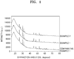
- 238000002441 X-ray diffraction Methods 0.000 description 5
- 239000011888 foil Substances 0.000 description 5
- 229910052732 germanium Inorganic materials 0.000 description 5
- 229920003048 styrene butadiene rubber Polymers 0.000 description 5
- 229910052719 titanium Inorganic materials 0.000 description 5
- LEONUFNNVUYDNQ-UHFFFAOYSA-N vanadium atom Chemical compound [V] LEONUFNNVUYDNQ-UHFFFAOYSA-N 0.000 description 5
- XKRFYHLGVUSROY-UHFFFAOYSA-N Argon Chemical compound [Ar] XKRFYHLGVUSROY-UHFFFAOYSA-N 0.000 description 4
- VYZAMTAEIAYCRO-UHFFFAOYSA-N Chromium Chemical compound [Cr] VYZAMTAEIAYCRO-UHFFFAOYSA-N 0.000 description 4
- LFQSCWFLJHTTHZ-UHFFFAOYSA-N Ethanol Chemical compound CCO LFQSCWFLJHTTHZ-UHFFFAOYSA-N 0.000 description 4
- 229910010848 Li6PS5Cl Inorganic materials 0.000 description 4
- 239000002033 PVDF binder Substances 0.000 description 4
- RTAQQCXQSZGOHL-UHFFFAOYSA-N Titanium Chemical compound [Ti] RTAQQCXQSZGOHL-UHFFFAOYSA-N 0.000 description 4
- 239000011149 active material Substances 0.000 description 4
- 230000008859 change Effects 0.000 description 4
- 229910052804 chromium Inorganic materials 0.000 description 4
- 230000007423 decrease Effects 0.000 description 4
- 238000011156 evaluation Methods 0.000 description 4
- 229910052738 indium Inorganic materials 0.000 description 4
- 239000011574 phosphorus Substances 0.000 description 4
- 229920001343 polytetrafluoroethylene Polymers 0.000 description 4
- 239000004810 polytetrafluoroethylene Substances 0.000 description 4
- 229920002981 polyvinylidene fluoride Polymers 0.000 description 4
- 230000002829 reductive effect Effects 0.000 description 4
- 239000000243 solution Substances 0.000 description 4
- 239000007858 starting material Substances 0.000 description 4
- XFXPMWWXUTWYJX-UHFFFAOYSA-N Cyanide Chemical compound N#[C-] XFXPMWWXUTWYJX-UHFFFAOYSA-N 0.000 description 3
- 229910015568 LiNi0.8Co0.15Mn0.05O2 Inorganic materials 0.000 description 3
- 229910008557 LiaNi1-b-cCob Inorganic materials 0.000 description 3
- 229910014968 LiaNi1−b−cCob Inorganic materials 0.000 description 3
- 229910014601 LiaNi1−b−cMnbB Inorganic materials 0.000 description 3
- 239000004698 Polyethylene Substances 0.000 description 3
- 239000006230 acetylene black Substances 0.000 description 3
- 125000004429 atom Chemical group 0.000 description 3
- 238000006243 chemical reaction Methods 0.000 description 3
- 210000001787 dendrite Anatomy 0.000 description 3
- 239000002270 dispersing agent Substances 0.000 description 3
- 239000000945 filler Substances 0.000 description 3
- 229910052733 gallium Inorganic materials 0.000 description 3
- 229910002804 graphite Inorganic materials 0.000 description 3
- 239000010439 graphite Substances 0.000 description 3
- ZMZDMBWJUHKJPS-UHFFFAOYSA-N hydrogen thiocyanate Natural products SC#N ZMZDMBWJUHKJPS-UHFFFAOYSA-N 0.000 description 3
- APFVFJFRJDLVQX-UHFFFAOYSA-N indium atom Chemical compound [In] APFVFJFRJDLVQX-UHFFFAOYSA-N 0.000 description 3
- 239000003273 ketjen black Substances 0.000 description 3
- 238000004519 manufacturing process Methods 0.000 description 3
- 150000002739 metals Chemical class 0.000 description 3
- VNWKTOKETHGBQD-UHFFFAOYSA-N methane Chemical compound C VNWKTOKETHGBQD-UHFFFAOYSA-N 0.000 description 3
- 230000003647 oxidation Effects 0.000 description 3
- 238000007254 oxidation reaction Methods 0.000 description 3
- 239000008188 pellet Substances 0.000 description 3
- 229920000573 polyethylene Polymers 0.000 description 3
- 238000001556 precipitation Methods 0.000 description 3
- 230000008569 process Effects 0.000 description 3
- 238000007086 side reaction Methods 0.000 description 3
- 239000002203 sulfidic glass Substances 0.000 description 3
- 238000012360 testing method Methods 0.000 description 3
- KVNYFPKFSJIPBJ-UHFFFAOYSA-N 1,2-diethylbenzene Chemical compound CCC1=CC=CC=C1CC KVNYFPKFSJIPBJ-UHFFFAOYSA-N 0.000 description 2
- JQMFQLVAJGZSQS-UHFFFAOYSA-N 2-[4-[2-(2,3-dihydro-1H-inden-2-ylamino)pyrimidin-5-yl]piperazin-1-yl]-N-(2-oxo-3H-1,3-benzoxazol-6-yl)acetamide Chemical compound C1C(CC2=CC=CC=C12)NC1=NC=C(C=N1)N1CCN(CC1)CC(=O)NC1=CC2=C(NC(O2)=O)C=C1 JQMFQLVAJGZSQS-UHFFFAOYSA-N 0.000 description 2
- UQSXHKLRYXJYBZ-UHFFFAOYSA-N Iron oxide Chemical compound [Fe]=O UQSXHKLRYXJYBZ-UHFFFAOYSA-N 0.000 description 2
- 229910009176 Li2S—P2 Inorganic materials 0.000 description 2
- 229910019142 PO4 Inorganic materials 0.000 description 2
- JDZCKJOXGCMJGS-UHFFFAOYSA-N [Li].[S] Chemical group [Li].[S] JDZCKJOXGCMJGS-UHFFFAOYSA-N 0.000 description 2
- 239000000654 additive Substances 0.000 description 2
- 238000004458 analytical method Methods 0.000 description 2
- 150000001450 anions Chemical class 0.000 description 2
- 229910052786 argon Inorganic materials 0.000 description 2
- 229910052785 arsenic Inorganic materials 0.000 description 2
- QVGXLLKOCUKJST-UHFFFAOYSA-N atomic oxygen Chemical compound [O] QVGXLLKOCUKJST-UHFFFAOYSA-N 0.000 description 2
- 229910052796 boron Inorganic materials 0.000 description 2
- 239000006229 carbon black Substances 0.000 description 2
- 239000002134 carbon nanofiber Substances 0.000 description 2
- 238000002425 crystallisation Methods 0.000 description 2
- 230000008025 crystallization Effects 0.000 description 2
- 230000003247 decreasing effect Effects 0.000 description 2
- 230000006866 deterioration Effects 0.000 description 2
- 238000001035 drying Methods 0.000 description 2
- 239000008151 electrolyte solution Substances 0.000 description 2
- 239000006232 furnace black Substances 0.000 description 2
- GNPVGFCGXDBREM-UHFFFAOYSA-N germanium atom Chemical compound [Ge] GNPVGFCGXDBREM-UHFFFAOYSA-N 0.000 description 2
- 239000011521 glass Substances 0.000 description 2
- 229910052736 halogen Inorganic materials 0.000 description 2
- 150000002367 halogens Chemical class 0.000 description 2
- 230000000670 limiting effect Effects 0.000 description 2
- GUWHRJQTTVADPB-UHFFFAOYSA-N lithium azide Chemical compound [Li+].[N-]=[N+]=[N-] GUWHRJQTTVADPB-UHFFFAOYSA-N 0.000 description 2
- 229910000625 lithium cobalt oxide Inorganic materials 0.000 description 2
- HSZCZNFXUDYRKD-UHFFFAOYSA-M lithium iodide Inorganic materials [Li+].[I-] HSZCZNFXUDYRKD-UHFFFAOYSA-M 0.000 description 2
- JILPJDVXYVTZDQ-UHFFFAOYSA-N lithium methoxide Chemical compound [Li+].[O-]C JILPJDVXYVTZDQ-UHFFFAOYSA-N 0.000 description 2
- BFZPBUKRYWOWDV-UHFFFAOYSA-N lithium;oxido(oxo)cobalt Chemical compound [Li+].[O-][Co]=O BFZPBUKRYWOWDV-UHFFFAOYSA-N 0.000 description 2
- 239000011259 mixed solution Substances 0.000 description 2
- 239000012454 non-polar solvent Substances 0.000 description 2
- 239000003960 organic solvent Substances 0.000 description 2
- 229910052760 oxygen Inorganic materials 0.000 description 2
- 239000001301 oxygen Substances 0.000 description 2
- 239000012688 phosphorus precursor Substances 0.000 description 2
- XPGAWFIWCWKDDL-UHFFFAOYSA-N propan-1-olate;zirconium(4+) Chemical compound [Zr+4].CCC[O-].CCC[O-].CCC[O-].CCC[O-] XPGAWFIWCWKDDL-UHFFFAOYSA-N 0.000 description 2
- 230000005855 radiation Effects 0.000 description 2
- 239000002904 solvent Substances 0.000 description 2
- 238000004544 sputter deposition Methods 0.000 description 2
- 239000010935 stainless steel Substances 0.000 description 2
- 229910001220 stainless steel Inorganic materials 0.000 description 2
- 229910052712 strontium Inorganic materials 0.000 description 2
- CIOAGBVUUVVLOB-UHFFFAOYSA-N strontium atom Chemical compound [Sr] CIOAGBVUUVVLOB-UHFFFAOYSA-N 0.000 description 2
- 239000000126 substance Substances 0.000 description 2
- 238000006467 substitution reaction Methods 0.000 description 2
- 229910000314 transition metal oxide Inorganic materials 0.000 description 2
- 229910019670 (NH4)H2PO4 Inorganic materials 0.000 description 1
- WTFUTSCZYYCBAY-SXBRIOAWSA-N 6-[(E)-C-[[4-[2-(2,3-dihydro-1H-inden-2-ylamino)pyrimidin-5-yl]piperazin-1-yl]methyl]-N-hydroxycarbonimidoyl]-3H-1,3-benzoxazol-2-one Chemical compound C1C(CC2=CC=CC=C12)NC1=NC=C(C=N1)N1CCN(CC1)C/C(=N/O)/C1=CC2=C(NC(O2)=O)C=C1 WTFUTSCZYYCBAY-SXBRIOAWSA-N 0.000 description 1
- DFGKGUXTPFWHIX-UHFFFAOYSA-N 6-[2-[4-[2-(2,3-dihydro-1H-inden-2-ylamino)pyrimidin-5-yl]piperazin-1-yl]acetyl]-3H-1,3-benzoxazol-2-one Chemical compound C1C(CC2=CC=CC=C12)NC1=NC=C(C=N1)N1CCN(CC1)CC(=O)C1=CC2=C(NC(O2)=O)C=C1 DFGKGUXTPFWHIX-UHFFFAOYSA-N 0.000 description 1
- 229910001148 Al-Li alloy Inorganic materials 0.000 description 1
- 229910001020 Au alloy Inorganic materials 0.000 description 1
- ZOXJGFHDIHLPTG-UHFFFAOYSA-N Boron Chemical compound [B] ZOXJGFHDIHLPTG-UHFFFAOYSA-N 0.000 description 1
- 229920000049 Carbon (fiber) Polymers 0.000 description 1
- 229910052684 Cerium Inorganic materials 0.000 description 1
- ZAMOUSCENKQFHK-UHFFFAOYSA-N Chlorine atom Chemical compound [Cl] ZAMOUSCENKQFHK-UHFFFAOYSA-N 0.000 description 1
- GYHNNYVSQQEPJS-UHFFFAOYSA-N Gallium Chemical compound [Ga] GYHNNYVSQQEPJS-UHFFFAOYSA-N 0.000 description 1
- 229910000927 Ge alloy Inorganic materials 0.000 description 1
- 229910008266 Li-Ag Inorganic materials 0.000 description 1
- 229910008029 Li-In Inorganic materials 0.000 description 1
- 229910008365 Li-Sn Inorganic materials 0.000 description 1
- 229910008405 Li-Zn Inorganic materials 0.000 description 1
- 229910009294 Li2S-B2S3 Inorganic materials 0.000 description 1
- 229910009292 Li2S-GeS2 Inorganic materials 0.000 description 1
- 229910009297 Li2S-P2S5 Inorganic materials 0.000 description 1
- 229910009298 Li2S-P2S5-Li2O Inorganic materials 0.000 description 1
- 229910009305 Li2S-P2S5-Li2O-LiI Inorganic materials 0.000 description 1
- 229910009311 Li2S-SiS2 Inorganic materials 0.000 description 1
- 229910009324 Li2S-SiS2-Li3PO4 Inorganic materials 0.000 description 1
- 229910009320 Li2S-SiS2-LiBr Inorganic materials 0.000 description 1
- 229910009316 Li2S-SiS2-LiCl Inorganic materials 0.000 description 1
- 229910009318 Li2S-SiS2-LiI Inorganic materials 0.000 description 1
- 229910009328 Li2S-SiS2—Li3PO4 Inorganic materials 0.000 description 1
- 229910009346 Li2S—B2S3 Inorganic materials 0.000 description 1
- 229910009351 Li2S—GeS2 Inorganic materials 0.000 description 1
- 229910009228 Li2S—P2S5 Inorganic materials 0.000 description 1
- 229910009219 Li2S—P2S5—Li2O Inorganic materials 0.000 description 1
- 229910009222 Li2S—P2S5—Li2O—LiI Inorganic materials 0.000 description 1
- 229910009433 Li2S—SiS2 Inorganic materials 0.000 description 1
- 229910007281 Li2S—SiS2—B2S3LiI Inorganic materials 0.000 description 1
- 229910007295 Li2S—SiS2—Li3PO4 Inorganic materials 0.000 description 1
- 229910007291 Li2S—SiS2—LiBr Inorganic materials 0.000 description 1
- 229910007288 Li2S—SiS2—LiCl Inorganic materials 0.000 description 1
- 229910007289 Li2S—SiS2—LiI Inorganic materials 0.000 description 1
- 229910007306 Li2S—SiS2—P2S5LiI Inorganic materials 0.000 description 1
- 229910010854 Li6PS5Br Inorganic materials 0.000 description 1
- 229910011103 Li7−xPS6−xClx Inorganic materials 0.000 description 1
- 229910052493 LiFePO4 Inorganic materials 0.000 description 1
- 229910013124 LiNiVO4 Inorganic materials 0.000 description 1
- 229910013410 LiNixCoyAlzO2 Inorganic materials 0.000 description 1
- 229910013467 LiNixCoyMnzO2 Inorganic materials 0.000 description 1
- 229910021466 LiQS2 Inorganic materials 0.000 description 1
- 229910012946 LiV2O5 Inorganic materials 0.000 description 1
- 229910021462 LiaCoGbO2 Inorganic materials 0.000 description 1
- 229910021464 LiaMn2GbO4 Inorganic materials 0.000 description 1
- 229910021461 LiaNiGbO2 Inorganic materials 0.000 description 1
- 229910021460 LiaNibCocMndGeO2 Inorganic materials 0.000 description 1
- 229910021459 LiaNibEcGdO2 Inorganic materials 0.000 description 1
- 229910008445 Li—Ag Inorganic materials 0.000 description 1
- 229910006670 Li—In Inorganic materials 0.000 description 1
- 229910006759 Li—Sn Inorganic materials 0.000 description 1
- 229910007049 Li—Zn Inorganic materials 0.000 description 1
- ZOKXTWBITQBERF-UHFFFAOYSA-N Molybdenum Chemical compound [Mo] ZOKXTWBITQBERF-UHFFFAOYSA-N 0.000 description 1
- CTQNGGLPUBDAKN-UHFFFAOYSA-N O-Xylene Chemical compound CC1=CC=CC=C1C CTQNGGLPUBDAKN-UHFFFAOYSA-N 0.000 description 1
- 229910000676 Si alloy Inorganic materials 0.000 description 1
- ZMZDMBWJUHKJPS-UHFFFAOYSA-M Thiocyanate anion Chemical compound [S-]C#N ZMZDMBWJUHKJPS-UHFFFAOYSA-M 0.000 description 1
- HCHKCACWOHOZIP-UHFFFAOYSA-N Zinc Chemical compound [Zn] HCHKCACWOHOZIP-UHFFFAOYSA-N 0.000 description 1
- QTHKJEYUQSLYTH-UHFFFAOYSA-N [Co]=O.[Ni].[Li] Chemical compound [Co]=O.[Ni].[Li] QTHKJEYUQSLYTH-UHFFFAOYSA-N 0.000 description 1
- HFCVPDYCRZVZDF-UHFFFAOYSA-N [Li+].[Co+2].[Ni+2].[O-][Mn]([O-])(=O)=O Chemical compound [Li+].[Co+2].[Ni+2].[O-][Mn]([O-])(=O)=O HFCVPDYCRZVZDF-UHFFFAOYSA-N 0.000 description 1
- XHCLAFWTIXFWPH-UHFFFAOYSA-N [O-2].[O-2].[O-2].[O-2].[O-2].[V+5].[V+5] Chemical compound [O-2].[O-2].[O-2].[O-2].[O-2].[V+5].[V+5] XHCLAFWTIXFWPH-UHFFFAOYSA-N 0.000 description 1
- 230000002411 adverse Effects 0.000 description 1
- 239000000443 aerosol Substances 0.000 description 1
- NDPGDHBNXZOBJS-UHFFFAOYSA-N aluminum lithium cobalt(2+) nickel(2+) oxygen(2-) Chemical compound [Li+].[O--].[O--].[O--].[O--].[Al+3].[Co++].[Ni++] NDPGDHBNXZOBJS-UHFFFAOYSA-N 0.000 description 1
- 239000003708 ampul Substances 0.000 description 1
- 229910052787 antimony Inorganic materials 0.000 description 1
- 239000012300 argon atmosphere Substances 0.000 description 1
- 238000000149 argon plasma sintering Methods 0.000 description 1
- RQNWIZPPADIBDY-UHFFFAOYSA-N arsenic atom Chemical compound [As] RQNWIZPPADIBDY-UHFFFAOYSA-N 0.000 description 1
- 150000001540 azides Chemical class 0.000 description 1
- 239000004917 carbon fiber Substances 0.000 description 1
- NKCVNYJQLIWBHK-UHFFFAOYSA-N carbonodiperoxoic acid Chemical compound OOC(=O)OO NKCVNYJQLIWBHK-UHFFFAOYSA-N 0.000 description 1
- 150000001768 cations Chemical class 0.000 description 1
- GWXLDORMOJMVQZ-UHFFFAOYSA-N cerium Chemical compound [Ce] GWXLDORMOJMVQZ-UHFFFAOYSA-N 0.000 description 1
- 238000004891 communication Methods 0.000 description 1
- 238000001816 cooling Methods 0.000 description 1
- OMZSGWSJDCOLKM-UHFFFAOYSA-N copper(II) sulfide Chemical compound [S-2].[Cu+2] OMZSGWSJDCOLKM-UHFFFAOYSA-N 0.000 description 1
- XLJMAIOERFSOGZ-UHFFFAOYSA-M cyanate Chemical compound [O-]C#N XLJMAIOERFSOGZ-UHFFFAOYSA-M 0.000 description 1
- 125000001651 cyanato group Chemical group [*]OC#N 0.000 description 1
- 238000000151 deposition Methods 0.000 description 1
- 238000011161 development Methods 0.000 description 1
- MNNHAPBLZZVQHP-UHFFFAOYSA-N diammonium hydrogen phosphate Chemical compound [NH4+].[NH4+].OP([O-])([O-])=O MNNHAPBLZZVQHP-UHFFFAOYSA-N 0.000 description 1
- 229910000388 diammonium phosphate Inorganic materials 0.000 description 1
- QHGJSLXSVXVKHZ-UHFFFAOYSA-N dilithium;dioxido(dioxo)manganese Chemical compound [Li+].[Li+].[O-][Mn]([O-])(=O)=O QHGJSLXSVXVKHZ-UHFFFAOYSA-N 0.000 description 1
- 238000007598 dipping method Methods 0.000 description 1
- BNIILDVGGAEEIG-UHFFFAOYSA-L disodium hydrogen phosphate Chemical compound [Na+].[Na+].OP([O-])([O-])=O BNIILDVGGAEEIG-UHFFFAOYSA-L 0.000 description 1
- 229910000397 disodium phosphate Inorganic materials 0.000 description 1
- VDQVEACBQKUUSU-UHFFFAOYSA-M disodium;sulfanide Chemical compound [Na+].[Na+].[SH-] VDQVEACBQKUUSU-UHFFFAOYSA-M 0.000 description 1
- 238000009826 distribution Methods 0.000 description 1
- 239000002001 electrolyte material Substances 0.000 description 1
- 238000010828 elution Methods 0.000 description 1
- XYIBRDXRRQCHLP-UHFFFAOYSA-N ethyl acetoacetate Chemical compound CCOC(=O)CC(C)=O XYIBRDXRRQCHLP-UHFFFAOYSA-N 0.000 description 1
- 238000004880 explosion Methods 0.000 description 1
- 239000007789 gas Substances 0.000 description 1
- 230000014509 gene expression Effects 0.000 description 1
- 230000009477 glass transition Effects 0.000 description 1
- 229910021389 graphene Inorganic materials 0.000 description 1
- 239000010442 halite Substances 0.000 description 1
- XLYOFNOQVPJJNP-UHFFFAOYSA-M hydroxide Chemical compound [OH-] XLYOFNOQVPJJNP-UHFFFAOYSA-M 0.000 description 1
- 230000006872 improvement Effects 0.000 description 1
- 239000011261 inert gas Substances 0.000 description 1
- 229910052746 lanthanum Inorganic materials 0.000 description 1
- FZLIPJUXYLNCLC-UHFFFAOYSA-N lanthanum atom Chemical compound [La] FZLIPJUXYLNCLC-UHFFFAOYSA-N 0.000 description 1
- 239000011244 liquid electrolyte Substances 0.000 description 1
- GELKBWJHTRAYNV-UHFFFAOYSA-K lithium iron phosphate Chemical compound [Li+].[Fe+2].[O-]P([O-])([O-])=O GELKBWJHTRAYNV-UHFFFAOYSA-K 0.000 description 1
- 229910003002 lithium salt Inorganic materials 0.000 description 1
- 159000000002 lithium salts Chemical class 0.000 description 1
- GLNWILHOFOBOFD-UHFFFAOYSA-N lithium sulfide Chemical compound [Li+].[Li+].[S-2] GLNWILHOFOBOFD-UHFFFAOYSA-N 0.000 description 1
- URIIGZKXFBNRAU-UHFFFAOYSA-N lithium;oxonickel Chemical compound [Li].[Ni]=O URIIGZKXFBNRAU-UHFFFAOYSA-N 0.000 description 1
- 229910052750 molybdenum Inorganic materials 0.000 description 1
- 239000011733 molybdenum Substances 0.000 description 1
- 230000007935 neutral effect Effects 0.000 description 1
- 229910052758 niobium Inorganic materials 0.000 description 1
- QJGQUHMNIGDVPM-UHFFFAOYSA-N nitrogen group Chemical group [N] QJGQUHMNIGDVPM-UHFFFAOYSA-N 0.000 description 1
- 239000004745 nonwoven fabric Substances 0.000 description 1
- 238000013021 overheating Methods 0.000 description 1
- 125000004430 oxygen atom Chemical group O* 0.000 description 1
- 230000000704 physical effect Effects 0.000 description 1
- 238000007747 plating Methods 0.000 description 1
- 239000002798 polar solvent Substances 0.000 description 1
- 229920003229 poly(methyl methacrylate) Polymers 0.000 description 1
- 229920002239 polyacrylonitrile Polymers 0.000 description 1
- 239000004926 polymethyl methacrylate Substances 0.000 description 1
- 239000011148 porous material Substances 0.000 description 1
- 229910052761 rare earth metal Inorganic materials 0.000 description 1
- 239000002994 raw material Substances 0.000 description 1
- 230000002441 reversible effect Effects 0.000 description 1
- 229910052706 scandium Inorganic materials 0.000 description 1
- SIXSYDAISGFNSX-UHFFFAOYSA-N scandium atom Chemical compound [Sc] SIXSYDAISGFNSX-UHFFFAOYSA-N 0.000 description 1
- 238000004626 scanning electron microscopy Methods 0.000 description 1
- 238000007650 screen-printing Methods 0.000 description 1
- 229910052711 selenium Inorganic materials 0.000 description 1
- 239000004065 semiconductor Substances 0.000 description 1
- 229910052979 sodium sulfide Inorganic materials 0.000 description 1
- 239000007921 spray Substances 0.000 description 1
- 238000005507 spraying Methods 0.000 description 1
- WWNBZGLDODTKEM-UHFFFAOYSA-N sulfanylidenenickel Chemical compound [Ni]=S WWNBZGLDODTKEM-UHFFFAOYSA-N 0.000 description 1
- 239000002345 surface coating layer Substances 0.000 description 1
- 229910052715 tantalum Inorganic materials 0.000 description 1
- 229910052714 tellurium Inorganic materials 0.000 description 1
- RYFMWSXOAZQYPI-UHFFFAOYSA-K trisodium phosphate Chemical compound [Na+].[Na+].[Na+].[O-]P([O-])([O-])=O RYFMWSXOAZQYPI-UHFFFAOYSA-K 0.000 description 1
- 229910000406 trisodium phosphate Inorganic materials 0.000 description 1
- 229910052720 vanadium Inorganic materials 0.000 description 1
- 229910001935 vanadium oxide Inorganic materials 0.000 description 1
- 238000007740 vapor deposition Methods 0.000 description 1
- 229920005609 vinylidenefluoride/hexafluoropropylene copolymer Polymers 0.000 description 1
- 239000008096 xylene Substances 0.000 description 1
- 229910052727 yttrium Inorganic materials 0.000 description 1
- VWQVUPCCIRVNHF-UHFFFAOYSA-N yttrium atom Chemical compound [Y] VWQVUPCCIRVNHF-UHFFFAOYSA-N 0.000 description 1
Images


Classifications
-
- H—ELECTRICITY
- H01—ELECTRIC ELEMENTS
- H01M—PROCESSES OR MEANS, e.g. BATTERIES, FOR THE DIRECT CONVERSION OF CHEMICAL ENERGY INTO ELECTRICAL ENERGY
- H01M10/00—Secondary cells; Manufacture thereof
- H01M10/05—Accumulators with non-aqueous electrolyte
- H01M10/056—Accumulators with non-aqueous electrolyte characterised by the materials used as electrolytes, e.g. mixed inorganic/organic electrolytes
- H01M10/0561—Accumulators with non-aqueous electrolyte characterised by the materials used as electrolytes, e.g. mixed inorganic/organic electrolytes the electrolyte being constituted of inorganic materials only
- H01M10/0562—Solid materials
-
- C—CHEMISTRY; METALLURGY
- C01—INORGANIC CHEMISTRY
- C01B—NON-METALLIC ELEMENTS; COMPOUNDS THEREOF; METALLOIDS OR COMPOUNDS THEREOF NOT COVERED BY SUBCLASS C01C
- C01B25/00—Phosphorus; Compounds thereof
- C01B25/08—Other phosphides
-
- C—CHEMISTRY; METALLURGY
- C01—INORGANIC CHEMISTRY
- C01B—NON-METALLIC ELEMENTS; COMPOUNDS THEREOF; METALLOIDS OR COMPOUNDS THEREOF NOT COVERED BY SUBCLASS C01C
- C01B25/00—Phosphorus; Compounds thereof
- C01B25/14—Sulfur, selenium, or tellurium compounds of phosphorus
-
- C—CHEMISTRY; METALLURGY
- C01—INORGANIC CHEMISTRY
- C01D—COMPOUNDS OF ALKALI METALS, i.e. LITHIUM, SODIUM, POTASSIUM, RUBIDIUM, CAESIUM, OR FRANCIUM
- C01D15/00—Lithium compounds
-
- H—ELECTRICITY
- H01—ELECTRIC ELEMENTS
- H01M—PROCESSES OR MEANS, e.g. BATTERIES, FOR THE DIRECT CONVERSION OF CHEMICAL ENERGY INTO ELECTRICAL ENERGY
- H01M10/00—Secondary cells; Manufacture thereof
- H01M10/05—Accumulators with non-aqueous electrolyte
- H01M10/052—Li-accumulators
-
- H—ELECTRICITY
- H01—ELECTRIC ELEMENTS
- H01M—PROCESSES OR MEANS, e.g. BATTERIES, FOR THE DIRECT CONVERSION OF CHEMICAL ENERGY INTO ELECTRICAL ENERGY
- H01M10/00—Secondary cells; Manufacture thereof
- H01M10/05—Accumulators with non-aqueous electrolyte
- H01M10/052—Li-accumulators
- H01M10/0525—Rocking-chair batteries, i.e. batteries with lithium insertion or intercalation in both electrodes; Lithium-ion batteries
-
- H—ELECTRICITY
- H01—ELECTRIC ELEMENTS
- H01M—PROCESSES OR MEANS, e.g. BATTERIES, FOR THE DIRECT CONVERSION OF CHEMICAL ENERGY INTO ELECTRICAL ENERGY
- H01M4/00—Electrodes
- H01M4/02—Electrodes composed of, or comprising, active material
- H01M4/13—Electrodes for accumulators with non-aqueous electrolyte, e.g. for lithium-accumulators; Processes of manufacture thereof
- H01M4/131—Electrodes based on mixed oxides or hydroxides, or on mixtures of oxides or hydroxides, e.g. LiCoOx
-
- H—ELECTRICITY
- H01—ELECTRIC ELEMENTS
- H01M—PROCESSES OR MEANS, e.g. BATTERIES, FOR THE DIRECT CONVERSION OF CHEMICAL ENERGY INTO ELECTRICAL ENERGY
- H01M4/00—Electrodes
- H01M4/02—Electrodes composed of, or comprising, active material
- H01M4/13—Electrodes for accumulators with non-aqueous electrolyte, e.g. for lithium-accumulators; Processes of manufacture thereof
- H01M4/133—Electrodes based on carbonaceous material, e.g. graphite-intercalation compounds or CFx
-
- H—ELECTRICITY
- H01—ELECTRIC ELEMENTS
- H01M—PROCESSES OR MEANS, e.g. BATTERIES, FOR THE DIRECT CONVERSION OF CHEMICAL ENERGY INTO ELECTRICAL ENERGY
- H01M4/00—Electrodes
- H01M4/02—Electrodes composed of, or comprising, active material
- H01M4/13—Electrodes for accumulators with non-aqueous electrolyte, e.g. for lithium-accumulators; Processes of manufacture thereof
- H01M4/134—Electrodes based on metals, Si or alloys
-
- H—ELECTRICITY
- H01—ELECTRIC ELEMENTS
- H01M—PROCESSES OR MEANS, e.g. BATTERIES, FOR THE DIRECT CONVERSION OF CHEMICAL ENERGY INTO ELECTRICAL ENERGY
- H01M4/00—Electrodes
- H01M4/02—Electrodes composed of, or comprising, active material
- H01M4/36—Selection of substances as active materials, active masses, active liquids
- H01M4/362—Composites
- H01M4/366—Composites as layered products
-
- H—ELECTRICITY
- H01—ELECTRIC ELEMENTS
- H01M—PROCESSES OR MEANS, e.g. BATTERIES, FOR THE DIRECT CONVERSION OF CHEMICAL ENERGY INTO ELECTRICAL ENERGY
- H01M4/00—Electrodes
- H01M4/02—Electrodes composed of, or comprising, active material
- H01M4/36—Selection of substances as active materials, active masses, active liquids
- H01M4/38—Selection of substances as active materials, active masses, active liquids of elements or alloys
- H01M4/381—Alkaline or alkaline earth metals elements
- H01M4/382—Lithium
-
- H—ELECTRICITY
- H01—ELECTRIC ELEMENTS
- H01M—PROCESSES OR MEANS, e.g. BATTERIES, FOR THE DIRECT CONVERSION OF CHEMICAL ENERGY INTO ELECTRICAL ENERGY
- H01M4/00—Electrodes
- H01M4/02—Electrodes composed of, or comprising, active material
- H01M4/36—Selection of substances as active materials, active masses, active liquids
- H01M4/38—Selection of substances as active materials, active masses, active liquids of elements or alloys
- H01M4/40—Alloys based on alkali metals
- H01M4/405—Alloys based on lithium
-
- H—ELECTRICITY
- H01—ELECTRIC ELEMENTS
- H01M—PROCESSES OR MEANS, e.g. BATTERIES, FOR THE DIRECT CONVERSION OF CHEMICAL ENERGY INTO ELECTRICAL ENERGY
- H01M4/00—Electrodes
- H01M4/02—Electrodes composed of, or comprising, active material
- H01M4/62—Selection of inactive substances as ingredients for active masses, e.g. binders, fillers
- H01M4/624—Electric conductive fillers
-
- H—ELECTRICITY
- H01—ELECTRIC ELEMENTS
- H01M—PROCESSES OR MEANS, e.g. BATTERIES, FOR THE DIRECT CONVERSION OF CHEMICAL ENERGY INTO ELECTRICAL ENERGY
- H01M4/00—Electrodes
- H01M4/02—Electrodes composed of, or comprising, active material
- H01M2004/026—Electrodes composed of, or comprising, active material characterised by the polarity
- H01M2004/027—Negative electrodes
-
- H—ELECTRICITY
- H01—ELECTRIC ELEMENTS
- H01M—PROCESSES OR MEANS, e.g. BATTERIES, FOR THE DIRECT CONVERSION OF CHEMICAL ENERGY INTO ELECTRICAL ENERGY
- H01M4/00—Electrodes
- H01M4/02—Electrodes composed of, or comprising, active material
- H01M2004/026—Electrodes composed of, or comprising, active material characterised by the polarity
- H01M2004/028—Positive electrodes
-
- H—ELECTRICITY
- H01—ELECTRIC ELEMENTS
- H01M—PROCESSES OR MEANS, e.g. BATTERIES, FOR THE DIRECT CONVERSION OF CHEMICAL ENERGY INTO ELECTRICAL ENERGY
- H01M2300/00—Electrolytes
- H01M2300/0017—Non-aqueous electrolytes
- H01M2300/0065—Solid electrolytes
- H01M2300/0068—Solid electrolytes inorganic
- H01M2300/0071—Oxides
-
- Y—GENERAL TAGGING OF NEW TECHNOLOGICAL DEVELOPMENTS; GENERAL TAGGING OF CROSS-SECTIONAL TECHNOLOGIES SPANNING OVER SEVERAL SECTIONS OF THE IPC; TECHNICAL SUBJECTS COVERED BY FORMER USPC CROSS-REFERENCE ART COLLECTIONS [XRACs] AND DIGESTS
- Y02—TECHNOLOGIES OR APPLICATIONS FOR MITIGATION OR ADAPTATION AGAINST CLIMATE CHANGE
- Y02E—REDUCTION OF GREENHOUSE GAS [GHG] EMISSIONS, RELATED TO ENERGY GENERATION, TRANSMISSION OR DISTRIBUTION
- Y02E60/00—Enabling technologies; Technologies with a potential or indirect contribution to GHG emissions mitigation
- Y02E60/10—Energy storage using batteries
Definitions
- the present disclosure relates to a solid electrolyte, an electrochemical cell including the solid electrolyte, and a method of preparing the solid electrolyte.
- lithium-ion batteries have been put to practical use in the automotive field as well as in information-related equipment and communication equipment.
- safety is particularly important because safety measures protect human lives.
- an all-solid battery may be safer than a lithium-ion battery using a liquid electrolyte.
- a sulfide-based solid electrolyte having an excellent ion conductivity is used as a solid electrolyte of an all-solid battery.
- the sulfide-based solid electrolyte has a weak stability towards oxidation at a high voltage, and thus there remains a need for an improved electrolyte.
- a solid electrolyte including nitrogen is provided.
- an electrochemical cell having improved rate capability and lifetime characteristics by including the solid electrolyte.
- a solid electrolyte includes a compound represented by Formula 1: Formula 1 (Li 1-a M a ) 7-d+x PS 6-d-x+k N x X d wherein, in Formula 1,
- an electrochemical cell includes a cathode layer; an anode layer; and a solid electrolyte layer disposed between the cathode layer and the anode layer, wherein at least one of the solid electrolyte layer and the cathode layer the includes the solid electrolyte according to an embodiment.
- a method of preparing a solid electrolyte including a compound of Formula 1 includes:
- X in the X precursor is Cl, Br, F, I, a pseudohalogen, or a combination thereof.
- the precursor mixture may further include an M precursor, wherein M of the M precursor is Na, K, Ca, Fe, Mg, Ag, Cu, Zr, Zn, or a combination thereof.
- a solid electrolyte includes a compound represented by Formula 1: Formula 1 (Li 1-a M a ) 7-d+x PS 6-d-x+k N x X d wherein, in Formula 1,
- relative terms such as “lower” or “bottom” and “upper” or “top,” may be used herein to describe one element's relationship to another element as illustrated in the Figures. It will be understood that relative terms are intended to encompass different orientations of the device in addition to the orientation depicted in the Figures. For example, if the device in one of the figures is turned over, elements described as being on the “lower” side of other elements would then be oriented on “upper” sides of the other elements. The exemplary term “lower,” can therefore, encompasses both an orientation of “lower” and “upper,” depending on the particular orientation of the figure.
- Exemplary embodiments are described herein with reference to cross section illustrations that are schematic illustrations of idealized embodiments. As such, variations from the shapes of the illustrations as a result, for example, of manufacturing techniques and/or tolerances, are to be expected. Thus, embodiments described herein should not be construed as limited to the particular shapes of regions as illustrated herein but are to include deviations in shapes that result, for example, from manufacturing. For example, a region illustrated or described as flat may, typically, have rough and/or nonlinear features. Moreover, sharp angles that are illustrated may be rounded. Thus, the regions illustrated in the figures are schematic in nature and their shapes are not intended to illustrate the precise shape of a region and are not intended to limit the scope of the present claims.
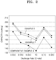
- a C-rate describes a discharge rate of a cell, and is obtained by dividing a total capacity of the cell by a total discharge period of time of 1 hour, e.g., a C-rate for a battery having a discharge capacity of 1.6 ampere-hours would be 1.6 amperes.
- argyrodite structure or “argyrodite crystal structure” means that the compound has a structure that is isostructural with argyrodite, Ag 8 GeS 6 .
- the term "pseudohalogen” refers to a molecule including two or more electronegative atoms, which in the free state show properties similar to halogens.
- the pseudohalogen generates anions which resemble halide ions.
- Examples of the pseudohalogen may include cyanide (CN), cyanate (OCN), thiocyanate (SCN), azide (N 3 - ), or a combination thereof.
- a solid electrolyte, an electrochemical cell including the solid electrolyte; and a method of preparing the solid electrolyte will be described in detail.
- a solid electrolyte including a compound represented by Formula 1: Formula 1 (Li 1-a M a ) 7-d+x PS 6-d-x+k N x X d wherein, in Formula 1,
- the value of k is determined so that the compound of Formula 1 is electrically neutral
- M is sodium (Na), potassium (K), or a combination thereof.
- An amount of nitrogen in the solid electrolyte may be in a range of greater than 0 mole percent (mol%) to about 10 mol%, for example, greater than 0 mol% to about 5 mol%, or, for example, about 1 mol% to about 5 mol%, based on the total amount of sulfur and nitrogen in the solid electrolyte.
- X of Formula 1 is Cl.
- X is Cl and at least one of F, Br, or I.
- X d may be Cl d , Br d , or (Br 1-x2 Cl x2 ) d , wherein 0 ⁇ x2 ⁇ 1 and 0 ⁇ d ⁇ 1.
- lithium mobility is increased by introducing an element having large atomic size into a sulfur (S) site to increase an ion conductivity of a sulfide-based solid electrolyte having an argyrodite crystal structure.
- S sulfur
- the sulfide-based solid electrolyte has weak oxidation stability, at a high voltage during charge, may form a resistance layer due to a reaction at an interface of the solid electrolyte and a cathode layer. The interface may result in an undesired increase in internal resistance, and thus improvement to avoid the increased resistance is desired.
- a solid electrolyte that has an argyrodite crystal structure that includes nitrogen (N) exhibits a stabilized interface due to a decrease in the presence of a resistance layer, which is understood to be caused by a reaction at an interface between a cathode and an electrolyte.
- the disclosed solid electrolyte has an argyrodite crystal structure and includes nitrogen (N), and has excellent ion conductivity at an equal level of an ion conductivity of lithium of prior art sulfide-based electrolytes having an argyrodite crystal structure, despite an increase in an amount of lithium due to the inclusion of nitrogen.
- the disclosed solid electrolyte provides improved stability at a high voltage. The improved stability is understood to result from decreased side reaction at an interface between the cathode layer and the electrolyte, which increases a discharge capacity, and thus an electrochemical cell having improved capacity retention and charge/discharge characteristics may be provided.
- X d is Cl d , Br d , or (Br 1-x1 Cl x1 ) d ; and 0 ⁇ x1 ⁇ 1 and 0 ⁇ d ⁇ 1.
- x1 may be, for example, in a range of about 0.1 to about 0.9, for example, about 0.2 to about 0.8, about 0.3 to about 0.7, or about 0.4 to about 0.6; or about 0.5.
- the compound represented by Formula 1 may be, for example, a compound represented by Formula 3, Formula 4, or a combination thereof: Formula 3 (Li 1-a Na a ) 7-d+x PS 6-d-x N x X d wherein in Formula 3, X is chlorine (Cl), bromine (Br), fluorine (F), iodine (I), a pseudohalogen, or a combination thereof; and 0 ⁇ x ⁇ 1, 0 ⁇ a ⁇ 1, and 0 ⁇ d ⁇ 1, or Formula 4 (Li 1-a K a ) 7-d+x PS 6-d-x N x X d wherein in Formula 4, X is chlorine (Cl), bromine (Br), fluorine (F), iodine (I), a pseudohalogen, or a combination thereof, and 0 ⁇ x ⁇ 1, 0 ⁇ d ⁇ 1, and 0 ⁇ a ⁇ 1.
- X may be a combination of Br and Cl, e.g., Br 1-x1 Cl x1 , wherein 0 ⁇ x1 ⁇ 1.
- the compound of Formula 1 may thus be, for example, a compound represented by Formula 5: Formula 5 Li 7-d+x PS 6-d-x N x (Br 1-x1 Cl x1 ) d wherein, in Formula 5, 0 ⁇ x ⁇ 1, 0 ⁇ d ⁇ 1, and 0 ⁇ x1 ⁇ 1.
- the compound represented by Formula 1 may be, for example, Li 6.125 PS 4.875 N 0.125 Cl, Li 6.25 PS 4.75 N 0.25 Cl, Li 6.5 PS 4.5 N 0.5 Cl, Li 6 Na 0.125 PS 4.875 N 0.125 Cl, Li 6 Na 0.25 PS 4.75 N 0.25 Cl, Li 6 K 0.125 PS 4.875 N 0.125 Cl, Li 6 K 0.25 PS 4.75 N 0.25 Cl, Li 6.125 PS 4.875 N 0.125 Cl 0.5 Br 0.5 , Li 6.25 PS 4.75 N 0.25 Cl 0.5 Br 0.5 , Li 6 Na 0.125 PS 4.875 N 0.125 Cl 0.5 Br 0.5 , Li 6 Na 0.25 PS 4.75 N 0.25 Cl 0.5 Br 0.5 , Li 6 K 0.125 PS 4.875 N 0.125 Cl 0.5 Br 0.5 , Li 6 K 0.125 PS 4.875 N 0.125 Cl 0.5 Br 0.5 , Li 6 K 0.25 PS 4.75 N 0.25 Cl 0.5 Br 0.5 , Li 6 K 0.125 PS 4.875 N 0.125 Cl 0.5 Br 0.5 , Li
- the solid electrolyte may be used as an electrolyte for an all-solid battery, e.g., between a cathode layer and an anode layer.
- the solid electrolyte may be used within the cathode layer and/or within the anode layer, e.g., as a cathode layer electrolyte material for an all-solid battery.
- the battery is a lithium-sulfur battery. Mentioned is an aspect where the solid electrolyte may be used as a cathode layer and/or an electrolyte of a lithium-sulfur battery.
- the solid electrolyte may be used as a cathode electrolyte or as an anode layer protection layer for a lithium metal battery.
- the anode layer protection layer may be on the anode layer and between the anode layer and the cathode layer.
- An ion conductivity of the solid electrolyte at 25 °C may be equal to or greater than about 1 millisiemen per centimeter (mS/cm), equal to or greater than about 1.3 mS/cm, equal to or greater than about 1.5 mS/cm, equal to or greater than about 1.6 mS/cm, equal to or greater than about 2.0 mS/cm, in a range of about 2.0 mS/cm to about 20 mS/cm, or in a range of about 2.0 mS/cm to about 10 mS/cm.
- the solid electrolyte may be applied as an electrolyte of an electrochemical cell.
- an electrochemical cell includes a cathode layer; an anode layer; and a solid electrolyte layer disposed between the cathode layer and the anode layer, wherein at least one of the solid electrolyte layer and the cathode layer includes the solid electrolyte comprising the compound of Formula 1.
- the solid electrolyte layer includes the solid electrolyte comprising the compound of Formula 1
- a side reaction e.g., with lithium metal in the anode layer, is suppressed, and thus cycle characteristics of the electrochemical cell may improve.
- the electrochemical cell may be, for example, an all-solid secondary battery or a lithium air battery, but are not limited thereto, and any suitable material or an electrochemical cell configuration may be used.
- the cathode layer may include a solid electrolyte including a compound represented by Formula 1: Formula 1 (Li 1-a M a ) 7-d+x PS 6-d-x+k N x X d wherein, in Formula 1,
- the compound of Formula 1 may be a compound represented by Formula 1-1: Formula 1-1 (Li 1-a M a ) 7-d+x PS 6-d-x N x X d wherein, in Formula 1-1,
- M is sodium (Na), potassium (K), or a combination thereof.
- an amount of the solid electrolyte may be in a range of about 2 parts by weight to about 70 parts by weight, for example, about 3 parts by weight to about 70 parts by weight, about 3 parts by weight to about 60 parts by weight, or, about 10 parts by weight to about 60 parts by weight, based on 100 parts by weight of a cathode active material in the cathode layer.
- the amount of the solid electrolyte is within these ranges, high-voltage stability of the electrochemical cell may improve.
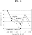
- a capacity retention is equal to or greater than about 85 % at a 100th cycle after charging to equal to or greater than 4 Volts, for example, 4.25V and discharging to 2.5 Volts the electrochemical cell in a constant-temperature chamber of 25 °C.
- the capacity retention of the electrochemical cell after charge/discharge of the cell between equal to or greater than 4 V and 2.5 V or less in a constant-temperature chamber of 25 °C may be for example, equal to or greater than about 86 %, equal to or greater than about 88 %, or in a range of about 88 % to about 99.5 % at 100 cycles.
- the solid electrolyte used in the active material layer in an all-solid-state secondary battery e.g., in a cathode active material layer of a cathode layer, or in an anode active material layer of an anode layer, may have a different particle size range than a solid electrolyte used in a solid electrolyte layer.
- the solid electrolyte used in the active material layer for example, has an average particle diameter, which is smaller than an average particle diameter of the solid electrolyte used in the solid electrolyte layer.
- the solid electrolyte used in the active material layer has an average particle diameter of about 100 nanometers (nm) to about 10 micrometers ( ⁇ m), about 300 nm to about 8 ⁇ m, or about 500 nm to about 5 ⁇ m.
- the solid electrolyte used in the solid electrolyte layer has an average particle diameter of about 500 nm to about 20 ⁇ m, about 700 nm to about 15 ⁇ m, or about 900 nm to about 10 ⁇ m.
- the particle diameter may be determined by light scattering or by SEM analysis, for example.
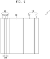
- an all-solid secondary battery 1 includes an anode layer 20 including an anode current collector 21 and a first anode active material layer 22; a cathode layer 10 including a cathode active material layer 12; and a solid electrolyte layer 30 disposed between the anode layer 20 and the cathode layer 10.
- the cathode layer 10 may include the solid electrolyte.
- the cathode layer 10 may include, for example, a cathode active material, a solid electrolyte, and a conducting agent.
- the anode layer 20 includes the anode current collector 21 and the first anode active material layer 22, and the first anode active material layer 22 includes an anode active material.
- the anode active material in the first anode active material layer 22 may be in the form of particles.
- An average particle diameter of the particles may be, for example, about 4 ⁇ m or less, about 3 ⁇ m or less, about 2 ⁇ m or less, about 1 ⁇ m or less, or about 900 nm or less.
- An average particle diameter of the particles may be, for example, in a range of about 10 nm to about 4 ⁇ m, about 10 nm to about 3 ⁇ m, about 10 nm to about 2 ⁇ m, about 10 nm to about 1 ⁇ m, or about 10 nm to about 900 nm.
- the average particle diameter of the anode active material may be, for example, a median diameter (D50) measured by using a laser diffraction particle diameter distribution meter.
- the anode active material in the first anode active material layer 22 may include, for example, at least one of a carbonaceous anode active material, a metal, or a metalloid.
- the carbonaceous anode active material may be, for example, amorphous carbon.
- amorphous carbon may include carbon black (CB), acetylene black (AB), furnace black (FB), Ketjen black (KB), and graphene, but are not limited thereto, and any suitable material available as amorphous carbon may be used.
- the amorphous carbon refers to carbon that has no crystallinity or a very low crystallinity, which may be different from crystalline carbon or graphite carbon.
- the metal or metalloid anode active material may include at least one of gold (Au), platinum (Pt), palladium (Pd), silicon (Si), silver (Ag), aluminum (Al), bismuth (Bi), tin (Sn), or zinc (Zn), but are not limited thereto, and any suitable material that is available as a metal anode active material or a metalloid anode active material capable of forming an alloy or a compound with lithium may be used.
- gold Au
- platinum (Pt) palladium
- silicon Si
- silver Ag
- nickel (Ni) does not form an alloy with lithium and thus is not a suitable metal anode active material.
- the first anode active material layer 22 may include one of these anode active materials or may include a mixture of a plurality of different anode active materials.
- the first anode active material layer 22 may only include amorphous carbon or may include at least one of gold (Au), platinum (Pt), palladium (Pd), silicon (Si), silver (Ag), aluminum (Al), bismuth (Bi), tin (Sn), or zinc (Zn).
- the first anode active material layer 22 may include a mixture including amorphous carbon and at least one of gold (Au), platinum (Pt), palladium (Pd), silicon (Si), silver (Ag), aluminum (Al), bismuth (Bi), tin (Sn), or zinc (Zn).
- a mixing ratio of amorphous carbon to an element such as gold in the mixture may be a weight ratio in a range of about 10:1 to about 1:2, about 5:1 to about 1:1, or about 4:1 to about 2:1, but are not limited thereto, and the mixing ratio may be selected according to characteristics of the all-solid secondary battery 1.
- the anode active material includes a mixture of amorphous carbon and at least one of gold (Au), platinum (Pt), palladium (Pd), silicon (Si), silver (Ag), aluminum (Al), bismuth (Bi), tin (Sn), or zinc (Zn) in the foregoing ratios
- cycle characteristics of the all-solid secondary battery 1 may further improve.
- the anode active material in the first anode active material layer 22 may include, for example, a mixture including first particles formed of amorphous carbon and second particles formed of a metal or a metalloid.
- the metal or the metalloid may include gold (Au), platinum (Pt), palladium (Pd), silicon (Si), silver (Ag), aluminum (Al), bismuth (Bi), tin (Sn), or zinc (Zn).
- the metalloid may be a semiconductor.
- An amount of the second particles may be in a range of about 8 weight% to about 60 weight%, about 10 weight% to about 50 weight%, about 15 weight% to about 40 weight%, or about 20 weight% to about 30 weight%, based on the total weight of the mixture. When the amount of the second particles is within these ranges, cycle characteristics of the all-solid secondary battery 1 may further improve.
- the first anode active material layer 22 may include a binder.
- the binder may include styrene-butadiene rubber (SBR), polytetrafluoroethylene (PTFE), polyvinylidene fluoride (PVDF), polyethylene, a vinylidene fluoride/hexafluoropropylene copolymer, polyacrylonitrile, and polymethylmethacrylate, but are not limited thereto, and any suitable material available as a binder may be used.
- the binder may comprise one of the examples of the binder alone or a plurality of binders.
- the first anode active material layer 22 When the first anode active material layer 22 includes the binder, the first anode active material layer 22 is stabilized on the anode current collector 21. Also, cracks in the first anode active material layer 22 may be suppressed despite of volume change and/or relative location change of the first anode active material layer 22 during charge/discharge. For example, when the first anode active material layer 22 does not include a binder, the first anode active material layer 22 may be easily separated from the anode current collector 21. When the first anode active material layer 22 is detached from the anode current collector 21, a possibility of a short-circuit occurring may increase as the anode current collector 21 contacts the solid electrolyte layer 30 at the exposed part of the anode current collector 21.
- the first anode active material layer 22 may be prepared by, for example, coating and drying a slurry on the anode current collector 21.
- the slurry includes dispersed materials for forming the first anode active material layer 22.
- the binder is included in the first anode active material layer 22, the anode active material may be stably dispersed in the slurry.
- clogging of screen e.g., screen clogging by an aggregate of the anode active material
- a thickness (d22) of the first anode active material layer 22 may be, for example, about 50% or less, about 40% or less, about 30% or less, about 20% or less, about 10% or less, or about 5% or less of a thickness (d12) of the cathode active material layer 12.
- a thickness (d22) of the first anode active material layer 22 may be in a range of about 1 ⁇ m to about 20 ⁇ m, about 2 ⁇ m to about 10 ⁇ m, or about 3 ⁇ m to about 7 ⁇ m.
- the thickness (d22) of the first anode active material layer 22 When the thickness (d22) of the first anode active material layer 22 is too thin, lithium dendrites formed between the first anode active material layer 22 and the anode current collector 21 destroys the first anode active material layer 22, and thus cycle characteristics of the all-solid secondary battery 1 may not improve.
- the thickness (d22) of the first anode active material layer 22 is too thick, an energy density of the all-solid secondary battery 1 deteriorates and an internal resistance of the all-solid secondary battery 1 by the first anode active material layer 22 increases, and thus cycle characteristics of the all-solid secondary battery 1 may not improve.
- a charge capacity of the first anode active material layer 22 decreases.
- the charge capacity of the first anode active material layer 22 may be, for example, about 50 % or less, about 40 % or less, about 30 % or less, about 20 % or less, about 10 % or less, about 5 % or less, or about 2 % or less of a charge capacity of the cathode active material layer 12.
- the charge capacity of the first anode active material layer 22 may be, for example, in a range of about 0.1 % to about 50 %, about 0.1 % to about 40 %, about 0.1 % to about 30 %, about 0.1 % to about 20 %, about 0.1 % to about 10 %, about 0.1 % to about 5 %, or about 0.1 % to about 2 % of a charge capacity of the cathode active material layer 12.
- the charge capacity of the cathode active material layer 12 is obtained by multiplying a charge capacity density (mAh/g) of the cathode active material by a weight of the cathode active material in the cathode active material layer 12.
- a value of a charge capacity density multiplied by a weight of each of the cathode active materials is calculated, and the total of these values refers to a charge capacity of the cathode active material layer 12.
- a charge capacity of the first anode active material layer 22 may be calculated in the same manner.
- a charge capacity of the first anode active material layer 22 is obtained by multiplying a charge capacity density (mAh/g) of the anode active material by a weight of the anode active material in the first anode active material layer 22.
- a value of a charge capacity density multiplied by a weight of each of the anode active materials is calculated, and the total of these values is a charge capacity of the first anode active material layer 22.
- the charge capacity densities of the cathode active material and the anode active material are obtained from capacities estimated by using an all-solid half-cell in which lithium metal is used as a reference electrode.
- the charge capacities of the cathode active material layer 12 and the first anode active material layer 22 are directly measured by charge capacity measurement using an all-solid half-cell. When the measured charge capacity is divided by a weight of each of the active materials, a charge capacity density may be obtained.
- the charge capacities of the cathode active material layer 12 and the first anode active material layer 22 may be initial charge capacities measured in the 1st charging cycle.
- the anode current collector 21 may be formed of, for example, a material that does not react with lithium or is not capable of forming an alloy or a compound with lithium. Examples of the material forming the anode current collector 21 may include copper (Cu), stainless steel, titanium (Ti), iron (Fe), cobalt (Co), or nickel (Ni), but are not limited thereto, and any suitable material available as an electrode current collector may be used.
- the anode current collector 21 may be formed of the metal or an alloy or a coating material of at least two metals.
- the anode current collector 21 may be, for example, in the form of a plate or a foil.
- the first anode active material layer 22 may further include additives that are used in an all-solid secondary battery 1, such as a filler, a dispersant, and an ion conducting agent.
- the all-solid secondary battery 1 may further include, for example, a thin film 24 on the anode current collector 21, the thin film 24 including an element alloyable with lithium.
- the thin film 24 is disposed between the anode current collector 21 and the first anode active material layer 22.
- the thin film 24 may include, for example, an element alloyable with lithium. Examples of the element alloyable with lithium may include gold, silver, zinc, tin, indium, silicon, aluminum, or bismuth, but are not limited thereto, and any suitable element alloyable with lithium may be used.
- the thin film 24 is formed of any of these metals or an alloy of various metals.
- the precipitation of the metal layer 23 may be further flattened between the thin film 24 and the first anode active material layer 22, and thus cycle characteristics of the all-solid secondary battery 1 may further improve.
- a thickness d24 of the thin film 24 may be, for example, in a range of about 1 nm to about 800 nm, about 10 nm to about 700 nm, about 50 nm to about 600 nm, or about 100 nm to about 500 nm.
- the thickness d24 of the thin film 24 is less than about 1 nm, the thin film 24 may not function properly.
- the thickness d24 of the thin film 24 is too thick, the thin film 24 itself absorbs lithium, and a precipitation amount of lithium in an anode may decrease, which results in deterioration of an energy density of the all-solid secondary battery 1, and thus cycle characteristics of the all-solid secondary battery 1 may be deteriorated.
- the thin film 24 may be disposed on the anode current collector 21 by using, for example, vacuum vapor deposition, sputtering, or plating, but not limited thereto, and any suitable method capable of forming a thin film may be used.
- the all-solid secondary battery 1 may further include, for example, a second anode active material layer 23 between the anode current collector 21 and the solid electrolyte layer 30 by charging of the all-solid secondary battery 1.
- the all-solid secondary battery 1 may further include, for example, a second anode active material layer 23 between the anode current collector 21 and the first anode active material layer 22 by charging of the all-solid secondary battery 1.
- the all-solid secondary battery 1 may further include, for example, a second anode active material layer 23 disposed between the solid electrolyte layer 30 and the first anode active material layer 22 by charging of the all-solid secondary battery 1.
- the all-solid secondary battery 1 may further include, for example, a second anode active material layer 23 in the first anode active material layer 22 by charging of the battery 1.
- the second anode active material layer is a metal layer including lithium or a lithium alloy.
- the metal layer includes lithium or a lithium alloy.
- the second anode active material layer 23 may function as, for example, a lithium reservoir.
- the lithium alloy may include a Li-Al alloy, a Li-Sn alloy, a Li-In alloy, a Li-Ag alloy, a Li-Au alloy, a Li-Zn alloy, a Li-Ge alloy, or a Li-Si alloy, but are not limited thereto, and any suitable material available as a lithium alloy in the art may be used.
- the second anode active material layer 23 may be formed of one of these alloys of lithium or may be formed of various alloys.
- a thickness d23 of the second anode active material layer 23 may be, for example, in a range of about 1 ⁇ m to about 1000 ⁇ m, about 1 ⁇ m to about 500 ⁇ m, about 1 ⁇ m to about 200 ⁇ m, about 1 ⁇ m to about 150 ⁇ m, about 1 ⁇ m to about 100 ⁇ m, or about 1 ⁇ m to about 50 ⁇ m, but is not limited thereto.
- the second anode active material layer 23 may not serve as a lithium reservoir.
- the second anode active material layer 23 may be, for example, a metal foil having a thickness in the range of about 1 ⁇ m to about 1000 ⁇ m.
- the second anode active material layer 23 may be disposed between the anode current collector 21 and the first anode active material layer 22 before assembling the all-solid secondary battery 1 or may be precipitated between the anode current collector 21 and the first anode active material layer 22 after assembling the all-solid secondary battery 1 by charging of the all-solid secondary battery 1.
- the second anode active material layer 23 is a metal layer including lithium and thus may function as a lithium reservoir.
- cycle characteristics of the all-solid secondary battery 1 including the second anode active material layer 23 may further improve.
- a lithium foil is disposed between the anode current collector 21 and the first anode active material layer 22 before assembling the all-solid secondary battery 1.
- the all-solid secondary battery 1 may be charged over a charge capacity of the first anode active material layer 22. That is, the first anode active material layer 22 is overcharged. In the beginning of the charging, lithium is absorbed in the first anode active material layer 22. That is, an anode active material in the first anode active material layer 22 may form an alloy or a compound with lithium ions migrated from the cathode layer 10.
- the second anode active material layer 23 is a metal layer comprising lithium, e.g. lithium metal or a lithium alloy. This occurs because, for example, the anode active material in the first anode active material layer 22 is formed of a material capable of forming an alloy or a compound with lithium.
- lithium of the first anode active material layer 22 and the second anode active material layer 23, i.e., a metal layer, is ionized and migrates towards the cathode layer 10.
- lithium may be used as an anode active material in the all-solid secondary battery 1.
- the first anode active material layer 22 covers the second anode active material layer 23
- the first anode active material layer 22 serves as a protection layer to the second anode active material layer 23 and suppresses precipitation growth of lithium dendrite at the same time.
- it may prevent a short-circuit and reduces capacity deterioration of the all-solid secondary battery 1, and as a result, cycle characteristics of the all-solid secondary battery 1 may improve.
- the anode current collector 21, the first anode active material layer 22, and a region therebetween are, for example, Li-free regions that do not include lithium metal or a lithium alloy in the initial state or an after-discharge state of the all-solid secondary battery 1.
- the all-solid secondary battery 1 may have a structure in which the second anode active material layer 23 is disposed on the anode current collector 21, and the solid electrolyte layer 30 is directly disposed on the second anode active material layer 23.
- the second anode active material layer 23 may be, for example, a lithium metal layer or a lithium alloy layer.
- the solid electrolyte layer 30 includes the sulfide-based solid electrolyte, a side reaction between the second anode active material layer 23, which is a lithium metal layer, and the solid electrolyte layer 30 is suppressed, and thus cycle characteristics of the all-solid secondary battery 1 may improve.
- the solid electrolyte layer 30 includes the solid electrolyte between the cathode layer 10 and the anode layer 20.
- the solid electrolyte may further include a second solid electrolyte in addition to the solid electrolyte of Formula 1.
- the solid electrolyte may further include at least one of Li 2 S-P 2 S 5 , Li 2 S-P 2 S 5 -LiX (where X is a halogen element), Li 2 S-P 2 S 5 -Li 2 O, Li 2 S-P 2 S 5 -Li 2 O-LiI, Li 2 S-SiS 2 , Li 2 S-SiS 2 -LiI, Li 2 S-SiS 2 -LiBr, Li 2 S-SiS 2 -LiCl, Li 2 S-SiS 2 -B 2 S 3 -LiI, Li 2 S-SiS 2 -P 2 S 5 -LiI, Li 2 S-B 2 S 3 , Li 2 S-P 2 S 5 -Z m Sn (where m and n are each a positive integer, and Z is one of Ge, Z
- the second solid electrolyte may be a sulfide-based solid electrolyte and may further include, for example, an argyrodite-type solid electrolyte represented by Formula 5-1: Formula 5-1 Li + 12-n-x A n+ X' 2- 6-x Y' - x wherein, in Formula 5-1,
- Examples of the argyrodite-type solid electrolyte may include at least one of Li 7-x PS 6-x Cl x (where 0 ⁇ x ⁇ 2), Li 7-x PS 6-x Br x (where 0 ⁇ x ⁇ 2), or Li 7-x PS 6-x I x (where 0 ⁇ x ⁇ 2).
- the argyrodite-type solid electrolyte particularly includes at least one of Li 6 PS 5 Cl, Li 6 PS 5 Br, or Li 6 PS 5 I.
- the solid electrolyte layer 30 may further include, for example, a binder.
- a binder included in the solid electrolyte layer 30 may include styrene butadiene rubber (SBR), polytetrafluoroethylene, polyvinylidene fluoride, polyethylene, or a combination thereof, but are not limited thereto, and any suitable material available as a binder may be used.
- SBR styrene butadiene rubber
- the binder of the solid electrolyte layer 30 may be identical to or different from the binders of the cathode active material layer 12 and the first anode active material layer 22.
- the cathode layer 10 includes the cathode current collector 11 and the cathode active material layer 12.
- the cathode current collector 11 may be a plate or a foil formed of, for example, indium (In), copper (Cu), magnesium (Mg), stainless steel, titanium (Ti), iron (Fe), cobalt (Co), nickel (Ni), zinc (Zn), aluminum (Al), germanium (Ge), lithium (Li), or an alloy thereof.
- the cathode current collector 11 may be omitted.
- the cathode active material layer 12 may include, for example, a cathode active material and a solid electrolyte.
- the solid electrolyte in the cathode active material layer 10 may be similar to or different from the solid electrolyte in the solid electrolyte layer 30.
- the solid electrolyte in the cathode active material layer may be the same as the solid electrolyte layer 30.
- the cathode active material layer 12 may include the solid electrolyte according to an embodiment.
- a cathode layer may include a cathode active material, and the cathode active material may be a compound capable of reversibly absorbing and desorbing lithium ions.
- the cathode active material may be, for example, at least one of a lithium transition metal oxide having a layered crystal structure, a lithium transition metal oxide having an olivine crystal structure, or a lithium transition metal oxide having a spinel crystal structure.
- the cathode active material may include a lithium transition metal oxide such as a lithium cobalt oxide (LCO), a lithium nickel oxide, a lithium nickel cobalt oxide, a lithium nickel cobalt aluminum oxide (NCA), a lithium nickel cobalt manganate (NCM), a lithium manganate, or a lithium iron phosphate; a nickel sulfide; a copper sulfide; a lithium sulfide; an iron oxide; or a vanadium oxide, but are not limited thereto, and any suitable material available as a cathode active material may be used.
- the cathode active material may be formed of a single material or as a mixture of at least two of the cathode active materials.
- the cathode active material may be a compound represented by at least one of the following formulae: Li a A 1-b B' b D 2 (where 0.90 ⁇ a ⁇ 1 and 0 ⁇ b ⁇ 0.5); Li a E 1-b B' b O 2-c D c (where 0.90 ⁇ a ⁇ 1, 0 ⁇ b ⁇ 0.5, and 0 ⁇ c ⁇ 0.05); LiE 2-b B' b O 4-c D c (where 0 ⁇ b ⁇ 0.5 and 0 ⁇ c ⁇ 0.05); Li a Ni 1-b-c Co b B' c D ⁇ (where 0.90 ⁇ a ⁇ 1, 0 ⁇ b ⁇ 0.5, 0 ⁇ c ⁇ 0.05, and 0 ⁇ ⁇ ⁇ 2); Li a Ni 1-b-c Co b B' c O 2- ⁇ F' ⁇ (where 0.90 ⁇ a ⁇ 1, 0 ⁇ b ⁇ 0.5, 0
- the compounds listed above as cathode active materials may have a surface coating layer (hereinafter, also referred to as "coating layer").
- a surface coating layer hereinafter, also referred to as "coating layer”
- the coating layer may include, for example, a coating element compound of an oxide, a hydroxide, an oxyhydroxide, an oxycarbonate, or a hydroxycarbonate of the coating element.
- the compounds for the coating layer may be amorphous or crystalline.
- the coating element for the coating layer may be magnesium (Mg), aluminum (Al), cobalt (Co), potassium (K), sodium (Na), calcium (Ca), silicon (Si), titanium (Ti), vanadium (V), tin (Sn), germanium (Ge), gallium (Ga), boron (B), arsenic (As), zirconium (Zr), or a combination thereof.
- the coating layer may be formed using any method that does not adversely affect the physical properties of the cathode active material.
- the coating layer may be formed using a spray coating method or a dipping method. Any suitable coating method may be used.
- the cathode active material may include, for example, a lithium salt of a transition metal oxide that has a layered rock-salt type structure among the examples of the lithium transition metal oxide.
- the "layered rock-salt type structure” refers to a structure in which an oxygen atom layer and a metal atom layer are alternately and regularly arranged in a ⁇ 111> direction in a cubic rock-salt type structure, where each of the atom layers forms a two-dimensional flat plane.
- the "cubic rock-salt type structure” refers to a sodium chloride (NaCl) type structure, which is one of the crystalline structures, in particular, to a structure in which face-centered cubic (fcc) lattices respectively formed of anions and cations are shifted by only a half of the ridge of each unit lattice.
- NaCl sodium chloride
- fcc face-centered cubic
- NCA LiNi x Co y Al z O 2
- NCM LiNi x Co y Mn z O 2
- the cathode active material may be covered by a coating layer.
- the coating layer is any suitable material that may be used as a coating layer of a cathode active material of an all-solid secondary battery.
- the coating layer may be, for example, Li 2 O-ZrO 2 .
- the cathode active material includes nickel (Ni) as a ternary lithium transition metal oxide such as NCA or NCM
- Ni nickel
- NCA ternary lithium transition metal oxide
- a capacity density of the all-solid secondary battery increases, Also, in a charged state of the all-solid-state battery using the cathode active material, metal elution from the cathode active material may be reduced. As a result, the cycle characteristics of the all-solid secondary battery improve.
- a shape of the cathode active material may be, for example, in the form of a particle including a true spherical shape or an elliptical shape.
- a particle diameter of the cathode active material is not particularly limited and may be in a range applicable to a cathode active material of an all-solid secondary battery.
- An amount of the cathode active material of the cathode layer is not particularly limited and may be in a suitable range applicable to a cathode layer of an all-solid secondary battery.
- the cathode layer may further include, for example, additives such as a conducting agent, a binder, a filler, a dispersant, or an ion conducting agent in addition to the cathode active material and the solid electrolyte.
- additives such as a conducting agent, a binder, a filler, a dispersant, or an ion conducting agent in addition to the cathode active material and the solid electrolyte.
- the conducting agent may include graphite, carbon black, acetylene black, Ketjen black, carbon fiber, or a metal powder.
- the binder may include styrene butadiene rubber (SBR), polytetrafluoroethylene, polyvinylidene fluoride, or polyethylene.
- SBR styrene butadiene rubber
- the filler, the dispersant, or the ion conducting agent that may be added to the cathode layer may be materials that are suitable in an electrode of an all-solid
- a method of preparing a solid electrolyte includes mixing a sulfur (S) precursor, a phosphorus (P) precursor, an X precursor, and a nitrogen (N) precursor to prepare a precursor mixture; and mixing the precursor mixture to prepare a solid electrolyte precursor, and then heat-treating the solid electrolyte precursor at a temperature about 300 °C or higher.
- X of the X precursor may be chlorine (Cl), bromine (Br), fluorine (F), iodine (I), a pseudohalogen, or a combination thereof.
- At least one of the sulfur precursor, phosphorus precursor, X precursor, or nitrogen precursor may include lithium.
- Examples of the sulfur precursor may include Li 2 S, and examples of the phosphorus precursor may include P 2 S 5 , red phosphorus, white phosphorus, phosphorus powders, (NH 4 )2HPO 4 , (NH 4 )H 2 PO 4 , Na 2 HPO 4 , or Na 3 PO 4 .
- Examples of the nitrogen precursor may include Li 3 N or N 2 S 3 .
- Examples of the X precursor may include a lithium halide.
- Examples of the lithium halide may include LiCl, LiI, or LiBr.
- the precursor mixture may further include an M precursor.
- M of the M precursor may be sodium (Na), potassium (K), calcium (Ca), iron (Fe), magnesium (Mg), silver (Ag), copper (Cu), zirconium (Zr), zinc (Zn), or a combination thereof.
- the mixing of the precursor mixture may include, for example, reacting the mixture to obtain a solid electrolyte precursor. Also, the solid electrolyte precursor is heat-treated at a temperature equal to or greater than about 300 °C to prepare a solid electrolyte.
- the solid electrolyte may include nitrogen and thus may extend a temperature range at which an ion conductive phase is formed.
- the heat-treating temperature may be, for example, in a range of about 300 °C to about 600 °C, about 300 °C to about 550 °C, or about 350 °C to about 500 °C.
- a solid electrolyte does not have an argyrodite crystal structure.
- examples of the method may include a mechanical milling (MM).
- MM mechanical milling
- starting materials such as Li 2 S or P 2 S 5 are reacted by stirring with a ball mill to prepare a solid electrolyte precursor.
- a stirring rate and a stirring time of the mechanical milling are not particularly limited, a production rate of the solid electrolyte precursor increases as the stirring rate increases, and a conversion rate of the starting materials to the solid electrolyte precursor may increase as the stirring time increases.
- the solid electrolyte precursor obtained by the mechanical milling is heat-treated at a predetermined temperature, and then the solid electrolyte precursor is pulverized to prepare a solid electrolyte in the form of a particle.
- the solid electrolyte may be changed from amorphous to crystalline by the heat-treatment.
- a temperature for the heat-treating may be, for example, in a range of about 400 °C to about 600 °C. When the temperature for the heat-treating is within this range, a solid electrolyte having a uniform composition may be obtained.
- the heat-treating time may vary depending on the temperature of the heat-treating, and, for example, the heat-treating may be performed for about 1 hour to about 100 hours, about 10 hours to about 80 hours, about 10 hours to about 50 hours, about 10 hours to about 30 hours, or about 10 hours to about 20 hours.
- the time for the heat-treating is within these ranges, the solid electrolyte may have excellent ion conductivity and high-temperature stability.
- An atmosphere for the heat-treating is an inert atmosphere or vacuum atmosphere.
- Examples of the atmosphere for the heat-treating may include nitrogen and argon, but are not limited thereto, and any suitable material available as an inert atmosphere may be used.
- a thickness of the solid electrolyte may be in a range of about 10 ⁇ m to about 200 ⁇ m. When the thickness of the solid electrolyte is within this range, the all-solid secondary battery may have improved cycle characteristics and improved capacity retention.
- a method of preparing an all-solid secondary battery may include preparing a solid electrolyte by using the method described above; preparing, for example, a cathode layer 10, an anode layer 20, and/or a solid electrolyte layer 30 each separately by using the solid electrolyte; and stacking these layers.
- a thickness of the solid electrolyte layer 30 may be in a range of about 10 ⁇ m to about 200 ⁇ m.
- first anode active material layer 22 Materials forming a first anode active material layer 22, such as an anode active material, a conducting agent, a binder, and a solid electrolyte are added to a polar solvent or a non-polar solvent to prepare a slurry.
- the slurry is coated and dried on an anode current collector 21 to prepare a first stack.
- the dried first stack is pressed to prepare an anode layer 20.
- the pressing of the first stack may be performed by using a roll press or a flat press, but embodiments are not limited thereto, and any suitable pressing method available may be used. The pressing may be omitted.
- the anode layer includes an anode current collector and a first anode active material layer including an anode active material disposed on the anode current collector, wherein the anode active material includes at least one of a carbonaceous anode active material or a metal or metalloid anode active material, wherein the carbonaceous anode active material includes at least one of amorphous carbon or crystalline carbon.
- the metal or metalloid anode active material is at least one of gold (Au), platinum (Pt), palladium (Pd), silicon (Si), silver (Ag), aluminum (Al), bismuth (Bi), tin (Sn), or zinc (Zn).
- the anode layer may further include a second anode active material layer disposed between the anode current collector and the first anode active material layer or between the solid electrolyte layer and the first anode active material layer, wherein the second anode active material layer is a metal layer including lithium or a lithium alloy.
- a cathode active material layer 12 such as a cathode active material, a conducting agent, a binder, and a starting material for the solid electrolyte are added to a non-polar solvent to prepare a slurry.
- the slurry is coated and dried on a cathode current collector 11 to prepare a stack.
- the stack is pressed to prepare a cathode layer 10.
- the pressing of the stack may be performed by using a roll press, a flat press, or an isostatic press, but is not limited thereto, and any suitable pressing method available may be used. The pressing may be omitted.
- the mixture of the materials forming the cathode active material layer 12 is densification-molded in the form of a pellet or extension-molded in the form of sheet to prepare a cathode layer 10.
- a cathode current collector 11 may be omitted.
- a solid electrolyte layer 30 includes the solid electrolyte.
- the solid electrolyte layer 30 may further include a sulfide-based solid electrolyte that is used in an all-solid secondary battery, in addition to the solid electrolyte disclosed herein.
- the sulfide-based solid electrolyte may be prepared, for example, by mixing, coating and drying, and pressing a starting material for the sulfide-based solid electrolyte, a solvent, and a binder.
- the sulfide-based solid electrolyte prepared by using the method of preparing a sulfide-based solid electrolyte may be vapor-deposited by using a film-forming method, such as an aerosol deposition method, a cold spray method, or a sputtering method, to prepare a solid electrolyte.
- the solid electrolyte may be prepared by pressing of a substance of the solid electrolyte particles.
- the cathode layer 10, the anode layer 20, and the solid electrolyte layer 30 prepared by using the method are stacked such that the solid electrolyte layer 30 is between the cathode layer 10 and the anode layer 20 and then pressed to prepare an all-solid secondary battery 1.
- the solid electrolyte layer 30 is disposed on the cathode layer 10 to prepare a second stack. Then, the anode layer 20 is disposed on the second stack such that the first anode active material layer contacts the solid electrolyte layer 30 to prepare a third stack, and the third stack is pressed to prepare an all-solid secondary battery 1.
- the pressing may be performed at a temperature, for example, in a range of room temperature (about 20 °C to about 25 °C) to about 90 °C. In an embodiment, the pressing may be performed at a temperature of about 100 °C or greater than 100 °C. The pressing is performed, for example, for about 30 minutes or less, about 20 minutes or less, about 15 minutes or less, or about 10 minutes or less.
- the pressing is performed, for example, for about 1 minute to about 30 minutes, about 1 minute to about 20 minutes, about 1 minute to about 15 minutes, or about 1 minute to about 10 minutes.
- a method of the pressing may be performed by using an isostatic press, a roll press, or a flat press, but is not limited thereto, and any suitable pressing method may be used.
- a pressure for the pressing may be, for example, about 500 megapascals (MPa) or less, about 400 MPa or less, about 300 MPa or less, about 200 MPa or less, or about 100 MPa or less.
- a pressure for the pressing may be, for example, in a range of about 50 MPa to about 500 MPa, about 50 MPa to about 480 MPa, about 50 MPa to about 450 MPa, about 50 MPa to about 400 MPa, about 50 MPa to about 350 MPa, about 50 MPa to about 300 MPa, about 50 MPa to about 250 MPa, about 50 MPa to about 200 MPa, about 50 MPa to about 150 MPa, or about 50 MPa to about 100 MPa.
- the solid electrolyte powder may be sintered by the pressing and form one solid electrolyte.
- the structure and the preparation method of the all-solid secondary battery are examples, where members of the structure and steps of the preparation method may be appropriately modified.
- Li 2 S, P 2 S 5 , LiCl, and Li 3 N were mixed to obtain a precursor mixture, amounts of Li 2 S, P 2 S 5 , LiCl, and Li 3 N in the preparation of the precursor mixture were each measured at a stoichiometric ratio to obtain Li 6.125 PS 4.875 N 0.125 Cl, and the resultant was mixed by performing a mechanical milling treatment for 20 hours by using a high energy mill (Pulverisette 7). The mechanical milling treatment was performed at a rotation rate of 380 rpm, at 25 °C, and in an argon atmosphere for 20 hours to obtain a powder material.
- a mechanical milling treatment was performed at a rotation rate of 380 rpm, at 25 °C, and in an argon atmosphere for 20 hours to obtain a powder material.
- a solid electrolyte was obtained in the same manner as in Example 1, except that the amounts of Li 2 S, P 2 S 5 , LiCl, and Li 3 N were stoichiometrically selected to obtain L1 6.25 PS 4.75 N 0.25 Cl and that the heat-treatment was performed at 500 °C for 12 hours.
- the amount of nitrogen is 5 mol% based on the total amount of sulfur and nitrogen.
- a solid electrolyte was obtained in the same manner as in Example 1, except that the amounts of Li 2 S, P 2 S 5 , LiCl, and Li 3 N were stoichiometrically selected to obtain L1 6.5 PS 4.5 N 0.5 Cl and that the heat-treatment was performed at 500 °C for 12 hours.
- the amount of nitrogen is 10 mol% based on the total amount of sulfur and nitrogen.
- a solid electrolyte was obtained in the same manner as in Example 1, except that LiBr was further used in the preparation of a precursor mixture, the amounts of Li 2 S, P 2 S 5 , LiCl, LiBr, and Li 3 N were stoichiometrically selected to obtain Li 6.25 PS 4.75 N 0.25 Cl 0.5 Br 0.5 , and the heat-treatment was performed at 450 °C for 12 hours.
- a solid electrolyte was obtained in the same manner as in Example 1, except that the amounts of Li 2 S, Na 2 S, K 2 S, P 2 S 5 , LiCl, LiBr, and Li 3 N were stoichiometrically selected to obtain a solid electrolyte having a composition shown in Table 1.
- Table 1 Sample Solid electrolyte Temperature and time for heat-treatment 5-1 Li 6 Na 0.125 PS 4.875 N 0.125 Cl 500 °C for 12 hours 5-2 L1 6 Na 0.125 PS 4.875 N 0.125 Cl 0.5 Br 0.5 450 °C for 12 hours 5-3 Li 6.1 PS 4.9 N 0.1 Cl 500 °C for 12 hours 5-4 Li 6.5 PS 5.5 N 0.5 Cl 500 °C for 12 hours 5-5 L1 5.9 K 0.1 Na 0.125 PS 4.875 N 0.125 Cl 500 °C for 12 hours
- Example 5-5 represents a solid electrolyte in which a portion of lithium (Li) of a solid electrolyte was substituted with potassium (K) and a portion of sulfur (S) was substituted with nitrogen (N).
- a solid electrolyte was obtained in the same manner as in Example 1, except that Li 2 S, P 2 S 5 , and LiCl were used for the preparation of the precursor mixture, the amounts of Li 2 S, P 2 S 5 , and LiCl were stoichiometrically selected to obtain Li 6 PS 5 Cl, and the heat-treatment was performed at 500 °C for 12 hours.
- a solid electrolyte was obtained in the same manner as in Example 1, except that the heat-treatment was performed at 250 °C.
- the target argyrodite-type solid electrolyte was not obtained in Comparative Example 2.
- LiN 3 (lithium azide), S 8 , Li 2 S, and P 2 S 5 were prepared in a stoichiometric ratio under an argon gas atmosphere and a mixture of the same was inserted in a graphite halite ampoule and melted in a vacuum condition. Subsequently, heat treatment was performed on the resultant at 550 °C in a tubular furnace for 6 days. After the heat treatment, Li 6 PS 5 N 3 was obtained by slowly cooling the mixture.
- Li 6 PS 5 N 3 obtained according to Comparative Example 3, did not have a crystal structure in which N 3 substitutes sulfur(S) as in the argyrodite-type solid electrolyte of Example 1.
- a particulate solid electrolyte glass was obtained in the same manner as Comparative Example 1, except that a raw material composition 0.5360 g of Li 2 S, 0.8910 g of P 2 S 5 , 0.2861 g of LiI, 0.2785 g of LiBr, and 0.0084 g of Li 3 N (with high purity, manufactured by a chemical company) was used for the precursor mixture.
- an amount of Li 3 N was 1.13 mol% based on 100 mol% of the sum of Li 2 S, P 2 S 5 , LiI, LiBr and Li 3 N.
- An amorphous sulfide solid electrolyte including nitrogen(N) was obtained by heating the prepared electrolyte glass under an inert gas atmosphere at a crystallization temperature or a temperature greater than a crystallization temperature, for 3 hours.
- the amorphous sulfide solid electrolyte was obtained according to Comparative Example 3A.
- An ion conductivity of the amorphous sulfide solid electrolyte is about 0.3 mS/cm, which was reduced compared to Example 1.
- a cathode active material having an aLi 2 O-ZrO 2 coating layer was prepared in the same manner disclosed in Korean Patent No. 10-2016-0064942 .
- the cathode active material was prepared as follows.
- the coating solution for coating aLi 2 O-ZrO 2 was mixed with LiNi 0.8 Co 0.15 Mn 0.05 O 2 (NCM) as a cathode active material, and this mixed solution was heated to about 40 °C while stirring to evaporate a solvent, such as an alcohol, therefrom. An ultrasonic wave was radiated to the mixed solution.
- NCM LiNi 0.8 Co 0.15 Mn 0.05 O 2
- An amount of Li 2 O-ZrO 2 (LZO) is about 0.4 parts by weight, based on 100 parts by weight of NCM.
- LiNi 0.8 Co 0.15 Mn 0.05 O 2 (NCM) having an aLi 2 O-ZrO 2 coating layer was obtained.
- NCM LiNi 0.8 Co 0.15 Mn 0.05 O 2
- LiNi 0.8 Co 0.15 Mn 0.05 O 2 (NCM) coated with Li 2 O-ZrO 2 (LZO) obtained in Preparation Example 1 was prepared as a cathode active material.
- the solid electrolyte powder prepared in Example 1 was prepared as a solid electrolyte.
- the cathode sheet was pressed on a cathode current collector formed of a carbon-coated aluminum foil having a thickness of 18 ⁇ m to prepare a cathode layer.
- the cathode layer was about 100 ⁇ m.
- a lithium metal having a thickness of about 30 ⁇ m was used as an anode layer.
- a styrene-butadiene rubber (SBR) binder was added to a crystalline argyrodite-type solid electrolyte (Li 6 PS 5 Cl) to prepare a mixture.
- the amount of a styrene-butadiene rubber (SBR) binder was 1 part by weight based on 100 parts by weight of the crystalline argyrodite-type solid electrolyte (Li 6 PS 5 Cl).
- Xylene and diethylbenzene were added to the mixture while stirring to prepare a slurry.
- the slurry was coated on a non-woven fabric by using a blade coater and dried at a temperature of 40 °C in the air to prepare a laminate.
- the laminate was vacuum-dried at a temperature of 40 °C for 12 hours. By following this process, a solid electrolyte layer was prepared.
- the solid electrolyte layer was disposed on the anode layer, and the cathode layer was disposed on the solid electrolyte layer to prepare a laminate.
- This laminate was plate press-treated at a temperature of 25 °C and a pressure of 100 MPa for 10 minutes. Due to the press-treatment, the solid electrolyte layer was sintered, and thus cell characteristics of all-solid secondary batteries were improved.
- Example 5 includes Example 5-1 to 5-5.
- Powders of the solid electrolytes prepared in Examples 1 and 2 were each put into a mold having a diameter of 10 mm and pressed at a pressure of 350 MPa to mold into a pellet. Two surfaces of the pellet were coated with an indium (In) thin film to prepare a sample for ion conductivity measurement. An impedance of the sample was measured by using an Autolab PGSTAT30 potentiostat (Metrohm Autolab Co. Ltd.), the Nyquist plot was drawn, and ion conductivities of the sample at 25 °C, 45 °C, or 60 °C were measured therefrom.
- the solid electrolyte of Example 1 had improved ion conductivities compared to those of the solid electrolyte of Comparative Example 1 at temperatures of 25 °C, 45 °C, and 60 °C, and the solid electrolyte of Example 2 had an ion conductivity equal to or greater than 1 mS/cm, which confirmed that the solid electrolyte had an ion conductivity appropriate to a solid electrolyte for an all-solid secondary battery.
- ion conductivities of the solid electrolyte of Example 3 were also evaluated in the same manner performed on the solid electrolyte of Example 1. As a result, the ion conductivities of the solid electrolyte of Example 3 were similar to those of the solid electrolyte of Example 1.
- Powder of the solid electrolyte prepared according to Example 5-1 to 5-5 was prepared, as a sample for measuring an ion conductivity, by the same method of the solid electrolyte powder of Example 1.
- Table 3 Sample Ion conductivity (mS/cm)(25°C) 5-1 2.5 5-2 3 5-3 2.19 5-4 1.45 5-5 0.6
- the solid electrolyte of Example 5-1 exhibited a greater ion conductivity, due to Na substitution, than the solid electrolyte of Example 1.
- the solid electrolyte of Example 5-2 exhibited greater ion conductivity, due to Br substitution in the composition of the solid electrolyte of Example 5-2, than the solid electrolyte of Example 5-1.
- the solid electrolyte of Example 5-3 exhibited an ion conductivity at the same level as the solid electrolyte of Example 1, and the solid electrolyte of Example 5-4 exhibited an ion conductivity at 1.5 mS/cm or lower the same as the solid electrolyte of Example 2.
- K was substituted, and had a lower ion conductivity than Example 5-1.
- X-ray diffraction (XRD) spectra of the solid electrolytes prepared in Examples 1 and 2 and Comparative Example 1 were measured, and the results are shown in FIG. 1 .
- the XRD analysis was performed by using D8 Advance (available from Bruker), using Cu K ⁇ radiation.
- the solid electrolytes of Examples 1 and 2 also had an argyrodite crystal structure as did the solid electrolyte of Comparative Example 1.
- Charge/discharge characteristics of the all-solid secondary batteries of Examples 6 and 7 and Comparative Example 4 were evaluated by using the following charge/discharge test.
- the charge/discharge test was performed by placing the all-solid secondary batteries in a constant-temperature chamber of 25 °C.
- the all-solid secondary batteries were charged with a constant current at a rate of 0.1 C for 10 hours until the battery voltage was 4.25 volts (V) and then discharged at a constant current at a rate of 0.05 C for 20 hours until the battery voltage reached 2.5 V (1st cycle).
- the batteries were charged with a constant current at a rate of 0.1 C for 10 hours until the battery voltage was 4.25 V and then discharged at a constant current at a rate of 0.33 C for 3 hours until the battery voltage reached 2.5 V (2nd cycle).
- the batteries were charged with a constant current at a rate of 0.1 C for 10 hours until the battery voltage was 4.25 V. Then, the batteries were discharged at a constant current at a rate of 0.5 C for 2 hours until the battery voltage reached 2.5 V (3rd cycle).
- the batteries were charged with a constant current at a rate of 0.1 C for 10 hours until the battery voltage was 4.25 V. Then, the batteries were discharged at a constant current at a rate of 1 C for 1 hour until the battery voltage reached 2.5 V (4th cycle).
- the batteries were charged with a constant current at a rate of 0.1 C for 10 hours until the battery voltage was 4.25 V. Then, the batteries were discharged at a constant current at a rate of 0.1 C for 10 hours until the battery voltage reached 2.5 V (5th cycle).
- the batteries were charged with a constant current at a rate of 0.33 C for 3 hours until the battery voltage was 4.25 V. Then, the batteries were discharged at a constant current at a rate of 0.33 C for 3 hours until the battery voltage reached 2.5 V (6th cycle).
- Charge/discharge characteristics of the all-solid secondary batteries of Examples 6 and 7 using the solid electrolytes of Examples 1 and 2 and charge/discharge characteristics of the all-solid secondary battery of Comparative Example 4 using the solid electrolyte of Comparative Example 1 were evaluated by using the following charge/discharge test.
- the charge/discharge cycle characteristics were evaluated by placing the all-solid secondary batteries in a constant-temperature chamber of 25 °C.
- the all-solid secondary batteries were charged with a constant current at a rate of 0.1 C for 10 hours until the battery voltage was 4.25 V and then discharged at a constant current at a rate of 0.05 C for 20 hours until the battery voltage reached 2.5 V (1st cycle). Subsequently, the batteries were charged with a constant current at a rate of 0.1 C for 10 hours until the battery voltage was 4.25 V and then discharged at a constant current at a rate of 0.33 C for 3 hours until the battery voltage reached 2.5 V (2nd cycle). Next, the batteries were charged with a constant current at a rate of 0.1 C for 10 hours until the battery voltage was 4.25 V.
- the batteries were discharged at a constant current at a rate of 0.5 C for 2 hours until the battery voltage reached 2.5 V (3rd cycle).
- the batteries were charged with a constant current at a rate of 0.1 C for 10 hours until the battery voltage was 4.25 V.
- the batteries were discharged at a constant current at a rate of 1 C for 1 hour until the battery voltage reached 2.5 V (4th cycle).
- the batteries were charged with a constant current at a rate of 0.1 C for 10 hours until the battery voltage was 4.25 V.
- the batteries were discharged at a constant current at a rate of 0.1 C for 10 hours until the battery voltage reached 2.5 V (5th cycle).
- the batteries were charged with a constant current at a rate of 0.33 C for 3 hours until the battery voltage was 4.25 V and then discharged at a constant current at a rate of 0.33 C for 3 hours until the battery voltage reached 2.5 V.
- Capacity retention % Discharge capacity at each cycle / Discharge capacity at the 1 st cycle ⁇ 100 %
- Discharge capacity characteristics of the all-solid secondary batteries of Examples 6 and 7 were good as shown in FIG. 4 and the capacity retention of the all-solid secondary batteries of Examples 6 and 7 significantly improved as shown in FIG. 5 , compared to those of the all-solid secondary battery of Comparative Example 4.
- a solid electrolyte having improved rate characteristics and cycle characteristics while having excellent ion conductivity.
- an electrochemical cell having improved capacity retention rate and cycle characteristics may be prepared.
Abstract
Description
- The present disclosure relates to a solid electrolyte, an electrochemical cell including the solid electrolyte, and a method of preparing the solid electrolyte.
- Recently, development of a battery having high specific energy and increased safety has been actively carried out in accordance with industrial requirements. For example, lithium-ion batteries have been put to practical use in the automotive field as well as in information-related equipment and communication equipment. In the field of automobiles, safety is particularly important because safety measures protect human lives.
- Currently available lithium ion batteries use an electrolytic solution containing a flammable organic solvent, and thus there is a possibility of overheating and fire when a short circuit occurs. To provide improved safety, an all-solid battery using a solid electrolyte, instead of an electrolytic solution, has been proposed.
- In the all-solid battery, the possibility of a fire or an explosion, even when a short circuit occurs, may be greatly reduced by not using a flammable organic solvent. Therefore, an all-solid battery may be safer than a lithium-ion battery using a liquid electrolyte.
- A sulfide-based solid electrolyte having an excellent ion conductivity is used as a solid electrolyte of an all-solid battery. However, the sulfide-based solid electrolyte has a weak stability towards oxidation at a high voltage, and thus there remains a need for an improved electrolyte.
- Provided is a solid electrolyte including nitrogen.
- Provided is an electrochemical cell having improved rate capability and lifetime characteristics by including the solid electrolyte.
- Provided is a method of preparing the solid electrolyte.
- Additional aspects will be set forth in part in the description which follows and, in part, will be apparent from the description.
- According to an aspect, a solid electrolyte includes a compound represented by Formula 1:
Formula 1 (Li1-aMa)7-d+xPS6-d-x+kNxXd
wherein, in Formula 1, - M is Na, K, Ca, Fe, Mg, Ag, Cu, Zr, Zn, or a combination thereof;
- X is Cl, Br, F, I, a pseudohalogen, or a combination thereof; and
- 0<x<1, 0≤a<1, 0<d≤1.8, and 0≤k<1, and
- According to an aspect, an electrochemical cell includes a cathode layer; an anode layer; and a solid electrolyte layer disposed between the cathode layer and the anode layer, wherein at least one of the solid electrolyte layer and the cathode layer the includes the solid electrolyte according to an embodiment.
- According to an aspect, a method of preparing a solid electrolyte including a compound of Formula 1 includes:
- providing a Li precursor, a S precursor, a P precursor, an X precursor, a N precursor, and optionally an M precursor;
- mixing the Li precursor, the S precursor, the P precursor, the X precursor, the N precursor, and the M precursor if present, to prepare a solid electrolyte precursor; and
- heat-treating the solid electrolyte precursor at a temperature equal to or greater than about 300 °C to prepare the solid electrolyte including the compound of Formula 1,
Formula 1 (Li1-aMa)7-d+xPS6-d-x+kNxXd
wherein, in Formula 1,- M is Na, K, Ca, Fe, Mg, Ag, Cu, Zr, Zn, or a combination thereof,
- X is Cl, Br, F, I, a pseudohalogen, or a combination thereof, and
- 0<x<1, 0≤a<1, 0<d≤1.8, and 0≤k<1,
- According to an aspect, in the method of preparing the solid electrolyte, X in the X precursor is Cl, Br, F, I, a pseudohalogen, or a combination thereof.
- The precursor mixture may further include an M precursor, wherein M of the M precursor is Na, K, Ca, Fe, Mg, Ag, Cu, Zr, Zn, or a combination thereof.
- According to an aspect, a solid electrolyte includes a compound represented by Formula 1:
Formula 1 (Li1-aMa)7-d+xPS6-d-x+kNxXd
wherein, in Formula 1, - M is Na, K, or a combination thereof;
- X is Cl, Br, F, I, a pseudohalogen, or a combination thereof; and
- 0<x<1, 0≤a<1, 0<d≤1.8, and 0≤k<1, and
- The above and other aspects, features, and advantages of certain embodiments of the disclosure will be more apparent from the following description taken in conjunction with the accompanying drawings, in which:
-
FIG. 1 is a graph of intensity (arbitrary units (a.u.)) versus diffraction angle (°2θ) and shows the results of X-ray diffraction (XRD)analysis of solid electrolytes prepared in Examples 1 and 2 and Comparative Example 1, when analyzed by X-ray diffraction (XRD) using Cu Kα radiation; -
FIG. 2 is a graph of capacity (milliampere hours per gram (mAh/g)) versus discharge rate (C-rate) and illustrates capacity of all-solid secondary batteries of Examples 6 and 7 and an all-solid secondary battery of Comparative Example 4; -
FIG. 3 is a graph of capacity retention (%) versus discharge rate (C-rate) and illustrates capacity retention of the all-solid secondary batteries of Examples 6 and 7 and Comparative Example 4; -
FIG. 4 is a graph of discharge capacity (milliampere hours per gram (mAh/g)) versus number of charge/discharge cycles and illustrates change in discharge capacity according to the number of charge/discharge cycles of the all-solid secondary batteries prepared in Examples 6 and 7 and Comparative Example 4; -
FIG. 5 is a graph of capacity retention (%) versus number of charge/discharge cycles and illustrates capacity retention of the all-solid secondary batteries prepared in Examples 6 and 7 and Comparative Example 4; and -
FIGS. 6 to 8 are cross-sectional views of an embodiment of an all-solid secondary battery. - Reference will now be made in detail to embodiments, examples of which are illustrated in the accompanying drawings, wherein like reference numerals refer to like elements throughout. In this regard, the present embodiments may have different forms and should not be construed as being limited to the descriptions set forth herein. Accordingly, the embodiments are merely described below, by referring to the figures, to explain aspects. As used herein, the term "and/or" includes any and all combinations of one or more of the associated listed items. "At least one" is not to be construed as limiting "a" or "an." "Or" means "and/or." Expressions such as "at least one of," when preceding a list of elements, modify the entire list of elements and do not modify the individual elements of the list.
- It will be understood that when an element is referred to as being "on" another element, it can be directly on the other element or intervening elements may be present therebetween. In contrast, when an element is referred to as being "directly on" another element, there are no intervening elements present.
- It will be understood that, although the terms "first," "second," "third," etc. may be used herein to describe various elements, components, regions, layers, and/or sections, these elements, components, regions, layers, and/or sections should not be limited by these terms. These terms are only used to distinguish one element, component, region, layer, or section from another element, component, region, layer, or section. Thus, "a first element," "component," "region," "layer," or "section" discussed below could be termed a second element, component, region, layer, or section without departing from the teachings herein.
- The terminology used herein is for the purpose of describing particular embodiments only and is not intended to be limiting. As used herein, "a", "an," "the," and "at least one" do not denote a limitation of quantity, and are intended to include both the singular and plural, unless the context clearly indicates otherwise. For example, "an element" has the same meaning as "at least one element," unless the context clearly indicates otherwise. It will be further understood that the terms "comprises" and/or "comprising," or "includes" and/or "including" when used in this specification, specify the presence of stated features, regions, integers, steps, operations, elements, and/or components, but do not preclude the presence or addition of one or more other features, regions, integers, steps, operations, elements, components, and/or groups thereof.
- Furthermore, relative terms, such as "lower" or "bottom" and "upper" or "top," may be used herein to describe one element's relationship to another element as illustrated in the Figures. It will be understood that relative terms are intended to encompass different orientations of the device in addition to the orientation depicted in the Figures. For example, if the device in one of the figures is turned over, elements described as being on the "lower" side of other elements would then be oriented on "upper" sides of the other elements. The exemplary term "lower," can therefore, encompasses both an orientation of "lower" and "upper," depending on the particular orientation of the figure. Similarly, if the device in one of the figures is turned over, elements described as "below" or "beneath" other elements would then be oriented "above" the other elements. The exemplary terms "below" or "beneath" can, therefore, encompass both an orientation of above and below.
- "About" or "approximately" as used herein is inclusive of the stated value and means within an acceptable range of deviation for the particular value as determined by one of ordinary skill in the art, considering the measurement in question and the error associated with measurement of the particular quantity (i.e., the limitations of the measurement system). For example, "about" can mean within one or more standard deviations, or within ± 30%, 20%, 10% or 5% of the stated value.
- Unless otherwise defined, all terms (including technical and scientific terms) used herein have the same meaning as commonly understood by one of ordinary skill in the art to which this disclosure belongs. It will be further understood that terms, such as those defined in commonly used dictionaries, should be interpreted as having a meaning that is consistent with their meaning in the context of the relevant art and the present disclosure, and will not be interpreted in an idealized or overly formal sense unless expressly so defined herein.
- Exemplary embodiments are described herein with reference to cross section illustrations that are schematic illustrations of idealized embodiments. As such, variations from the shapes of the illustrations as a result, for example, of manufacturing techniques and/or tolerances, are to be expected. Thus, embodiments described herein should not be construed as limited to the particular shapes of regions as illustrated herein but are to include deviations in shapes that result, for example, from manufacturing. For example, a region illustrated or described as flat may, typically, have rough and/or nonlinear features. Moreover, sharp angles that are illustrated may be rounded. Thus, the regions illustrated in the figures are schematic in nature and their shapes are not intended to illustrate the precise shape of a region and are not intended to limit the scope of the present claims.
- A C-rate describes a discharge rate of a cell, and is obtained by dividing a total capacity of the cell by a total discharge period of time of 1 hour, e.g., a C-rate for a battery having a discharge capacity of 1.6 ampere-hours would be 1.6 amperes.
- As used herein, "argyrodite structure" or "argyrodite crystal structure" means that the compound has a structure that is isostructural with argyrodite, Ag8GeS6.
- As used herein, the term "pseudohalogen" refers to a molecule including two or more electronegative atoms, which in the free state show properties similar to halogens. The pseudohalogen generates anions which resemble halide ions. Examples of the pseudohalogen may include cyanide (CN), cyanate (OCN), thiocyanate (SCN), azide (N3 -), or a combination thereof.
- A solid electrolyte, an electrochemical cell including the solid electrolyte; and a method of preparing the solid electrolyte will be described in detail.
- According to an embodiment, provided is a solid electrolyte including a compound represented by Formula 1:
Formula 1 (Li1-aMa)7-d+xPS6-d-x+kNxXd
wherein, inFormula 1, - M is sodium (Na), potassium (K), calcium (Ca), iron (Fe), magnesium (Mg), silver (Ag), copper (Cu), zirconium (Zr), zinc (Zn), or a combination thereof;
- X is chlorine (Cl), bromine (Br), fluorine (F), iodine (I), a pseudohalogen, or a combination thereof; and
- 0<x<1, 0≤a<1, 0<d≤1.8, and 0≤k<1, and
- In
Formula 1, when M is a monovalent element such as sodium (Na), potassium (K), or silver (Ag), k=0; and when M is a divalent, trivalent or tetravalent element such as calcium (Ca), iron (Fe), magnesium (Mg), copper (Cu), zirconium (Zr), or zinc (Zn), 0<k<1. Here, the value of k is determined so that the compound ofFormula 1 is electrically neutral - In an aspect, the compound of
Formula 1, wherein k=0, may be a compound represented by Formula 1-1:
Formula 1-1 (Li1-aMa)7-d+xPS6-d-xNxXd
wherein, in Formula 1-1, - M is sodium (Na), potassium (K), calcium (Ca), iron (Fe), magnesium (Mg), silver (Ag), copper (Cu), zirconium (Zr), zinc (Zn), or a combination thereof;
- X is chlorine (Cl), bromine (Br), fluorine (F), iodine (I), a pseudohalogen, or a combination thereof; and
- 0<x<1, 0≤a<1, and 0<d≤1.8.
- In an aspect, M is sodium (Na), potassium (K), or a combination thereof.
- An amount of nitrogen in the solid electrolyte may be in a range of greater than 0 mole percent (mol%) to about 10 mol%, for example, greater than 0 mol% to about 5 mol%, or, for example, about 1 mol% to about 5 mol%, based on the total amount of sulfur and nitrogen in the solid electrolyte.
- In an aspect, in
Formulae 1 and 1-1, 0<x≤0.5. - In an aspect, in
Formulae 1 and 1-1, 0<d≤1. - In an aspect, X of
Formula 1 is Cl. - In an aspect, X is Cl and at least one of F, Br, or I.
- In
Formulae 1 and 1-1, Xd may be Cld, Brd, or (Br1-x2Clx2)d, wherein 0<x2<1 and 0<d≤1. - While not wanting to be bound by theory, it is understood that lithium mobility is increased by introducing an element having large atomic size into a sulfur (S) site to increase an ion conductivity of a sulfide-based solid electrolyte having an argyrodite crystal structure. The sulfide-based solid electrolyte has weak oxidation stability, at a high voltage during charge, may form a resistance layer due to a reaction at an interface of the solid electrolyte and a cathode layer. The interface may result in an undesired increase in internal resistance, and thus improvement to avoid the increased resistance is desired.
- When nitrogen is added to the solid electrolyte having an argyrodite crystal structure, ion conductivity is expected to be low due to reduced lithium pores and a decreased lattice volume, and thus studies thereon have not substantially been conducted.
- However, it has been unexpectedly discovered that a solid electrolyte that has an argyrodite crystal structure that includes nitrogen (N) exhibits a stabilized interface due to a decrease in the presence of a resistance layer, which is understood to be caused by a reaction at an interface between a cathode and an electrolyte. The disclosed solid electrolyte has an argyrodite crystal structure and includes nitrogen (N), and has excellent ion conductivity at an equal level of an ion conductivity of lithium of prior art sulfide-based electrolytes having an argyrodite crystal structure, despite an increase in an amount of lithium due to the inclusion of nitrogen. The disclosed solid electrolyte provides improved stability at a high voltage. The improved stability is understood to result from decreased side reaction at an interface between the cathode layer and the electrolyte, which increases a discharge capacity, and thus an electrochemical cell having improved capacity retention and charge/discharge characteristics may be provided.
- In an aspect, the argyrodite solid electrolyte may be, for example, a compound of
Formula 1, wherein k=0 and a=0, represented by Formula 2:
Formula 2 Li7-d+xPS6-d-xNxXd
wherein, inFormula 2, X is chlorine (Cl), bromine (Br), iodine (I), or a combination thereof; and 0<x<1 and 0<d≤1. - In
Formula - In
Formula 2, Xd is Cld, Brd, or (Br1-x1Clx1)d; and 0<x1<1 and 0<d≤1. x1 may be, for example, in a range of about 0.1 to about 0.9, for example, about 0.2 to about 0.8, about 0.3 to about 0.7, or about 0.4 to about 0.6; or about 0.5. - In an aspect, in
Formula 1, M may be Na or K, and k=0. The compound represented byFormula 1 may be, for example, a compound represented by Formula 3,Formula 4, or a combination thereof:
Formula 3 (Li1-aNaa)7-d+xPS6-d-xNxXd
wherein in Formula 3, X is chlorine (Cl), bromine (Br), fluorine (F), iodine (I), a
pseudohalogen, or a combination thereof; and 0<x<1, 0<a<1, and 0<d≤1, or
Formula 4 (Li1-aKa)7-d+xPS6-d-xNxXd
wherein inFormula 4, X is chlorine (Cl), bromine (Br), fluorine (F), iodine (I), a pseudohalogen, or a combination thereof, and 0<x<1, 0<d≤1, and 0<a<1. - In an aspect M is not present, i.e., a=0, and k=0. Also X may be a combination of Br and Cl, e.g., Br1-x1Clx1, wherein 0<x1<1. The compound of
Formula 1 may thus be, for example, a compound represented by Formula 5:
Formula 5 Li7-d+xPS6-d-xNx(Br1-x1Clx1)d
wherein, inFormula 5, 0<x<1, 0<d≤1, and 0<x1<1. - The compound represented by
Formula 1 may be, for example, Li6.125PS4.875N0.125Cl, Li6.25PS4.75N0.25Cl, Li6.5PS4.5N0.5Cl, Li6Na0.125PS4.875N0.125Cl, Li6Na0.25PS4.75N0.25Cl, Li6K0.125PS4.875N0.125Cl, Li6K0.25PS4.75N0.25Cl, Li6.125PS4.875N0.125Cl0.5Br0.5, Li6.25PS4.75N0.25Cl0.5Br0.5, Li6Na0.125PS4.875N0.125Cl0.5Br0.5, Li6Na0.25PS4.75N0.25Cl0.5Br0.5, Li6K0.125PS4.875N0.125Cl0.5Br0.5, Li6K0.25PS4.75N0.25Cl0.5Br0.5, Li6.125PS4.875N0.125 Cl0.16Br0.84, Li6.25PS4.75N0.25Cl0.16Br0.84, Li6Na0.125PS4.875N0.125Cl0.16Br0.84, Li6Na0.25PS4.75N0.25Cl0.16Br0.84, Li6K0.125PS4.875N0.125Cl0.16Br0.84, Li6K0.25PS4.75N0.25Cl0.16Br0.84, Li6.125PS4.875N0.125Br, Li6.25PS4.75N0.25Br, Li6Na0.125PS4.875N0.125Br, Li6Na0.25PS4.75N0.25Br, Li6K0.125PS4.875N0.125Br, Li6K0.25PS4.75N0.25Br, Li6.115Cu0.01PS4.88N0.125Cl, Li6.115Mg0.01PS4.88N0.125Cl, Li6.115Ca0.01PS4.88N0.125Cl, Li6.115Fe0.01PS4.88N0.125Cl, Li6.115Zn0.01PS4.88N0.125Cl, Li5.9K0.1Na0.125PS4.875N0.125Cl, or a combination thereof. - The solid electrolyte may be used as an electrolyte for an all-solid battery, e.g., between a cathode layer and an anode layer. In an aspect, the solid electrolyte may be used within the cathode layer and/or within the anode layer, e.g., as a cathode layer electrolyte material for an all-solid battery. In an aspect, the battery is a lithium-sulfur battery. Mentioned is an aspect where the solid electrolyte may be used as a cathode layer and/or an electrolyte of a lithium-sulfur battery.
- The solid electrolyte may be used as a cathode electrolyte or as an anode layer protection layer for a lithium metal battery. The anode layer protection layer may be on the anode layer and between the anode layer and the cathode layer.
- An ion conductivity of the solid electrolyte at 25 °C may be equal to or greater than about 1 millisiemen per centimeter (mS/cm), equal to or greater than about 1.3 mS/cm, equal to or greater than about 1.5 mS/cm, equal to or greater than about 1.6 mS/cm, equal to or greater than about 2.0 mS/cm, in a range of about 2.0 mS/cm to about 20 mS/cm, or in a range of about 2.0 mS/cm to about 10 mS/cm. When the solid electrolyte has a high ion conductivity of about 1 mS/cm or greater, the solid electrolyte may be applied as an electrolyte of an electrochemical cell.
- According to an embodiment, an electrochemical cell includes a cathode layer; an anode layer; and a solid electrolyte layer disposed between the cathode layer and the anode layer, wherein at least one of the solid electrolyte layer and the cathode layer includes the solid electrolyte comprising the compound of
Formula 1. When the solid electrolyte layer includes the solid electrolyte comprising the compound ofFormula 1, a side reaction, e.g., with lithium metal in the anode layer, is suppressed, and thus cycle characteristics of the electrochemical cell may improve. - The electrochemical cell may be, for example, an all-solid secondary battery or a lithium air battery, but are not limited thereto, and any suitable material or an electrochemical cell configuration may be used.
- In the electrochemical cell, the cathode layer may include a solid electrolyte including a compound represented by Formula 1:
Formula 1 (Li1-aMa)7-d+xPS6-d-x+kNxXd
wherein, inFormula 1, - M is sodium (Na), potassium (K), calcium (Ca), iron (Fe), magnesium (Mg), silver (Ag), copper (Cu), zirconium (Zr), zinc (Zn), or a combination thereof;
- X is chlorine (Cl), bromine (Br), fluorine (F), iodine (I), a pseudohalogen, or a combination thereof; and
- 0<x<1, 0≤a<1, 0<d≤1.8, and 0≤k<1, and
- For example, the compound of
Formula 1 may be a compound represented by Formula 1-1:
Formula 1-1 (Li1-aMa)7-d+xPS6-d-xNxXd
wherein, in Formula 1-1, - M is sodium (Na), potassium (K), silver (Ag), or a combination thereof;
- X is chlorine (Cl), bromine (Br), fluorine (F), iodine (I), a pseudohalogen, or a combination thereof; and
- 0<x<1, 0≤a<1, and 0<d≤1.8.
- In an aspect, M is sodium (Na), potassium (K), or a combination thereof.
- In the cathode layer, an amount of the solid electrolyte may be in a range of about 2 parts by weight to about 70 parts by weight, for example, about 3 parts by weight to about 70 parts by weight, about 3 parts by weight to about 60 parts by weight, or, about 10 parts by weight to about 60 parts by weight, based on 100 parts by weight of a cathode active material in the cathode layer. When the amount of the solid electrolyte is within these ranges, high-voltage stability of the electrochemical cell may improve.
- A capacity retention is equal to or greater than about 85 % at a 100th cycle after charging to equal to or greater than 4 Volts, for example, 4.25V and discharging to 2.5 Volts the electrochemical cell in a constant-temperature chamber of 25 °C. The capacity retention of the electrochemical cell after charge/discharge of the cell between equal to or greater than 4 V and 2.5 V or less in a constant-temperature chamber of 25 °C may be for example, equal to or greater than about 86 %, equal to or greater than about 88 %, or in a range of about 88 % to about 99.5 % at 100 cycles.
- The solid electrolyte used in the active material layer in an all-solid-state secondary battery, e.g., in a cathode active material layer of a cathode layer, or in an anode active material layer of an anode layer, may have a different particle size range than a solid electrolyte used in a solid electrolyte layer. The solid electrolyte used in the active material layer, for example, has an average particle diameter, which is smaller than an average particle diameter of the solid electrolyte used in the solid electrolyte layer.
- The solid electrolyte used in the active material layer has an average particle diameter of about 100 nanometers (nm) to about 10 micrometers (µm), about 300 nm to about 8 µm, or about 500 nm to about 5 µm. The solid electrolyte used in the solid electrolyte layer has an average particle diameter of about 500 nm to about 20 µm, about 700 nm to about 15 µm, or about 900 nm to about 10 µm. The particle diameter may be determined by light scattering or by SEM analysis, for example.
- Hereinafter, as an example of the electrochemical cell, an all-solid secondary battery will be described in detail.
- Referring to
FIGS. 6 to 8 , an all-solidsecondary battery 1 includes ananode layer 20 including an anodecurrent collector 21 and a first anodeactive material layer 22; acathode layer 10 including a cathodeactive material layer 12; and asolid electrolyte layer 30 disposed between theanode layer 20 and thecathode layer 10. Thecathode layer 10 may include the solid electrolyte. Thecathode layer 10 may include, for example, a cathode active material, a solid electrolyte, and a conducting agent. - Referring to
FIGS. 6 to 8 , theanode layer 20 includes the anodecurrent collector 21 and the first anodeactive material layer 22, and the first anodeactive material layer 22 includes an anode active material. - For example, the anode active material in the first anode
active material layer 22 may be in the form of particles. An average particle diameter of the particles may be, for example, about 4 µm or less, about 3 µm or less, about 2 µm or less, about 1 µm or less, or about 900 nm or less. An average particle diameter of the particles may be, for example, in a range of about 10 nm to about 4 µm, about 10 nm to about 3 µm, about 10 nm to about 2 µm, about 10 nm to about 1 µm, or about 10 nm to about 900 nm. When the average particle diameter of the anode active material is within these ranges, reversible absorbing and/or desorbing of lithium during charge/discharge may further be facilitated. The average particle diameter of the anode active material may be, for example, a median diameter (D50) measured by using a laser diffraction particle diameter distribution meter. - The anode active material in the first anode
active material layer 22 may include, for example, at least one of a carbonaceous anode active material, a metal, or a metalloid. - The carbonaceous anode active material may be, for example, amorphous carbon. Examples of the amorphous carbon may include carbon black (CB), acetylene black (AB), furnace black (FB), Ketjen black (KB), and graphene, but are not limited thereto, and any suitable material available as amorphous carbon may be used. The amorphous carbon refers to carbon that has no crystallinity or a very low crystallinity, which may be different from crystalline carbon or graphite carbon.
- For example, the metal or metalloid anode active material may include at least one of gold (Au), platinum (Pt), palladium (Pd), silicon (Si), silver (Ag), aluminum (Al), bismuth (Bi), tin (Sn), or zinc (Zn), but are not limited thereto, and any suitable material that is available as a metal anode active material or a metalloid anode active material capable of forming an alloy or a compound with lithium may be used. For example, nickel (Ni) does not form an alloy with lithium and thus is not a suitable metal anode active material.
- The first anode
active material layer 22 may include one of these anode active materials or may include a mixture of a plurality of different anode active materials. For example, the first anodeactive material layer 22 may only include amorphous carbon or may include at least one of gold (Au), platinum (Pt), palladium (Pd), silicon (Si), silver (Ag), aluminum (Al), bismuth (Bi), tin (Sn), or zinc (Zn). The first anodeactive material layer 22 may include a mixture including amorphous carbon and at least one of gold (Au), platinum (Pt), palladium (Pd), silicon (Si), silver (Ag), aluminum (Al), bismuth (Bi), tin (Sn), or zinc (Zn). A mixing ratio of amorphous carbon to an element such as gold in the mixture may be a weight ratio in a range of about 10:1 to about 1:2, about 5:1 to about 1:1, or about 4:1 to about 2:1, but are not limited thereto, and the mixing ratio may be selected according to characteristics of the all-solidsecondary battery 1. When the anode active material includes a mixture of amorphous carbon and at least one of gold (Au), platinum (Pt), palladium (Pd), silicon (Si), silver (Ag), aluminum (Al), bismuth (Bi), tin (Sn), or zinc (Zn) in the foregoing ratios, cycle characteristics of the all-solidsecondary battery 1 may further improve. - The anode active material in the first anode
active material layer 22 may include, for example, a mixture including first particles formed of amorphous carbon and second particles formed of a metal or a metalloid. Examples of the metal or the metalloid may include gold (Au), platinum (Pt), palladium (Pd), silicon (Si), silver (Ag), aluminum (Al), bismuth (Bi), tin (Sn), or zinc (Zn). The metalloid may be a semiconductor. An amount of the second particles may be in a range of about 8 weight% to about 60 weight%, about 10 weight% to about 50 weight%, about 15 weight% to about 40 weight%, or about 20 weight% to about 30 weight%, based on the total weight of the mixture. When the amount of the second particles is within these ranges, cycle characteristics of the all-solidsecondary battery 1 may further improve. - For example, the first anode
active material layer 22 may include a binder. Examples of the binder may include styrene-butadiene rubber (SBR), polytetrafluoroethylene (PTFE), polyvinylidene fluoride (PVDF), polyethylene, a vinylidene fluoride/hexafluoropropylene copolymer, polyacrylonitrile, and polymethylmethacrylate, but are not limited thereto, and any suitable material available as a binder may be used. The binder may comprise one of the examples of the binder alone or a plurality of binders. - When the first anode
active material layer 22 includes the binder, the first anodeactive material layer 22 is stabilized on the anodecurrent collector 21. Also, cracks in the first anodeactive material layer 22 may be suppressed despite of volume change and/or relative location change of the first anodeactive material layer 22 during charge/discharge. For example, when the first anodeactive material layer 22 does not include a binder, the first anodeactive material layer 22 may be easily separated from the anodecurrent collector 21. When the first anodeactive material layer 22 is detached from the anodecurrent collector 21, a possibility of a short-circuit occurring may increase as the anodecurrent collector 21 contacts thesolid electrolyte layer 30 at the exposed part of the anodecurrent collector 21. The first anodeactive material layer 22 may be prepared by, for example, coating and drying a slurry on the anodecurrent collector 21. The slurry includes dispersed materials for forming the first anodeactive material layer 22. When the binder is included in the first anodeactive material layer 22, the anode active material may be stably dispersed in the slurry. For example, when the slurry is coated on the anodecurrent collector 21 by using a screen printing method, clogging of screen (e.g., screen clogging by an aggregate of the anode active material) may be suppressed. - A thickness (d22) of the first anode
active material layer 22 may be, for example, about 50% or less, about 40% or less, about 30% or less, about 20% or less, about 10% or less, or about 5% or less of a thickness (d12) of the cathodeactive material layer 12. For example, a thickness (d22) of the first anodeactive material layer 22 may be in a range of about 1 µm to about 20 µm, about 2 µm to about 10 µm, or about 3 µm to about 7 µm. When the thickness (d22) of the first anodeactive material layer 22 is too thin, lithium dendrites formed between the first anodeactive material layer 22 and the anodecurrent collector 21 destroys the first anodeactive material layer 22, and thus cycle characteristics of the all-solidsecondary battery 1 may not improve. When the thickness (d22) of the first anodeactive material layer 22 is too thick, an energy density of the all-solidsecondary battery 1 deteriorates and an internal resistance of the all-solidsecondary battery 1 by the first anodeactive material layer 22 increases, and thus cycle characteristics of the all-solidsecondary battery 1 may not improve. - For example, when the thickness (d22) of the first anode
active material layer 22 decreases, a charge capacity of the first anodeactive material layer 22 decreases. The charge capacity of the first anodeactive material layer 22 may be, for example, about 50 % or less, about 40 % or less, about 30 % or less, about 20 % or less, about 10 % or less, about 5 % or less, or about 2 % or less of a charge capacity of the cathodeactive material layer 12. The charge capacity of the first anodeactive material layer 22 may be, for example, in a range of about 0.1 % to about 50 %, about 0.1 % to about 40 %, about 0.1 % to about 30 %, about 0.1 % to about 20 %, about 0.1 % to about 10 %, about 0.1 % to about 5 %, or about 0.1 % to about 2 % of a charge capacity of the cathodeactive material layer 12. When the charge capacity of the first anodeactive material layer 22 is too low, a thickness of the first anodeactive material layer 22 is too thin, lithium dendrites formed between the first anodeactive material layer 22 and the anodecurrent collector 21 during repeated charge/discharge operations destroys the first anodeactive material layer 22, and cycle characteristics of the all-solidsecondary battery 1 may not improve. When the charge capacity of the first anodeactive material layer 22 is too high, an energy density of the all-solidsecondary battery 1 deteriorates and an internal resistance of the all-solidsecondary battery 1 by the first anodeactive material layer 22 increases, and thus cycle characteristics of the all-solidsecondary battery 1 may not improve. - The charge capacity of the cathode
active material layer 12 is obtained by multiplying a charge capacity density (mAh/g) of the cathode active material by a weight of the cathode active material in the cathodeactive material layer 12. When various types of materials are used as the cathode active material, a value of a charge capacity density multiplied by a weight of each of the cathode active materials is calculated, and the total of these values refers to a charge capacity of the cathodeactive material layer 12. A charge capacity of the first anodeactive material layer 22 may be calculated in the same manner. That is, a charge capacity of the first anodeactive material layer 22 is obtained by multiplying a charge capacity density (mAh/g) of the anode active material by a weight of the anode active material in the first anodeactive material layer 22. When various types of materials are used as the anode active material, a value of a charge capacity density multiplied by a weight of each of the anode active materials is calculated, and the total of these values is a charge capacity of the first anodeactive material layer 22. Here, the charge capacity densities of the cathode active material and the anode active material are obtained from capacities estimated by using an all-solid half-cell in which lithium metal is used as a reference electrode. The charge capacities of the cathodeactive material layer 12 and the first anodeactive material layer 22 are directly measured by charge capacity measurement using an all-solid half-cell. When the measured charge capacity is divided by a weight of each of the active materials, a charge capacity density may be obtained. The charge capacities of the cathodeactive material layer 12 and the first anodeactive material layer 22 may be initial charge capacities measured in the 1st charging cycle. - The anode
current collector 21 may be formed of, for example, a material that does not react with lithium or is not capable of forming an alloy or a compound with lithium. Examples of the material forming the anodecurrent collector 21 may include copper (Cu), stainless steel, titanium (Ti), iron (Fe), cobalt (Co), or nickel (Ni), but are not limited thereto, and any suitable material available as an electrode current collector may be used. The anodecurrent collector 21 may be formed of the metal or an alloy or a coating material of at least two metals. The anodecurrent collector 21 may be, for example, in the form of a plate or a foil. - The first anode
active material layer 22 may further include additives that are used in an all-solidsecondary battery 1, such as a filler, a dispersant, and an ion conducting agent. - Referring to
FIG. 7 , the all-solidsecondary battery 1 may further include, for example, a thin film 24 on the anodecurrent collector 21, the thin film 24 including an element alloyable with lithium. The thin film 24 is disposed between the anodecurrent collector 21 and the first anodeactive material layer 22. The thin film 24 may include, for example, an element alloyable with lithium. Examples of the element alloyable with lithium may include gold, silver, zinc, tin, indium, silicon, aluminum, or bismuth, but are not limited thereto, and any suitable element alloyable with lithium may be used. The thin film 24 is formed of any of these metals or an alloy of various metals. When the thin film 24 is disposed on the anodecurrent collector 21, for example, the precipitation of themetal layer 23 may be further flattened between the thin film 24 and the first anodeactive material layer 22, and thus cycle characteristics of the all-solidsecondary battery 1 may further improve. - A thickness d24 of the thin film 24 may be, for example, in a range of about 1 nm to about 800 nm, about 10 nm to about 700 nm, about 50 nm to about 600 nm, or about 100 nm to about 500 nm. When the thickness d24 of the thin film 24 is less than about 1 nm, the thin film 24 may not function properly. When the thickness d24 of the thin film 24 is too thick, the thin film 24 itself absorbs lithium, and a precipitation amount of lithium in an anode may decrease, which results in deterioration of an energy density of the all-solid
secondary battery 1, and thus cycle characteristics of the all-solidsecondary battery 1 may be deteriorated. The thin film 24 may be disposed on the anodecurrent collector 21 by using, for example, vacuum vapor deposition, sputtering, or plating, but not limited thereto, and any suitable method capable of forming a thin film may be used. - Referring to
FIG. 8 , the all-solidsecondary battery 1 may further include, for example, a second anodeactive material layer 23 between the anodecurrent collector 21 and thesolid electrolyte layer 30 by charging of the all-solidsecondary battery 1. The all-solidsecondary battery 1 may further include, for example, a second anodeactive material layer 23 between the anodecurrent collector 21 and the first anodeactive material layer 22 by charging of the all-solidsecondary battery 1. Although not shown in the drawings, the all-solidsecondary battery 1 may further include, for example, a second anodeactive material layer 23 disposed between thesolid electrolyte layer 30 and the first anodeactive material layer 22 by charging of the all-solidsecondary battery 1. Although not shown in the drawings, the all-solidsecondary battery 1 may further include, for example, a second anodeactive material layer 23 in the first anodeactive material layer 22 by charging of thebattery 1. - The second anode active material layer is a metal layer including lithium or a lithium alloy. The metal layer includes lithium or a lithium alloy. In this regard, because the second anode
active material layer 23 is a metal layer including lithium, the second anodeactive material layer 23 may function as, for example, a lithium reservoir. Examples of the lithium alloy may include a Li-Al alloy, a Li-Sn alloy, a Li-In alloy, a Li-Ag alloy, a Li-Au alloy, a Li-Zn alloy, a Li-Ge alloy, or a Li-Si alloy, but are not limited thereto, and any suitable material available as a lithium alloy in the art may be used. The second anodeactive material layer 23 may be formed of one of these alloys of lithium or may be formed of various alloys. - A thickness d23 of the second anode
active material layer 23 may be, for example, in a range of about 1 µm to about 1000 µm, about 1 µm to about 500 µm, about 1 µm to about 200 µm, about 1 µm to about 150 µm, about 1 µm to about 100 µm, or about 1 µm to about 50 µm, but is not limited thereto. When the thickness d23 of the second anodeactive material layer 23 is too thin, the second anodeactive material layer 23 may not serve as a lithium reservoir. When the thickness d23 of the second anodeactive material layer 23 is too thick, a weight and a volume of the all-solidsecondary battery 1 increase and cycle characteristics may deteriorate. The second anodeactive material layer 23 may be, for example, a metal foil having a thickness in the range of about 1 µm to about 1000 µm. - In the all-solid
secondary battery 1, the second anodeactive material layer 23 may be disposed between the anodecurrent collector 21 and the first anodeactive material layer 22 before assembling the all-solidsecondary battery 1 or may be precipitated between the anodecurrent collector 21 and the first anodeactive material layer 22 after assembling the all-solidsecondary battery 1 by charging of the all-solidsecondary battery 1. - When the second anode
active material layer 23 is disposed between the anodecurrent collector 21 and the first anodeactive material layer 22 before assembling the all-solidsecondary battery 1, the second anodeactive material layer 23 is a metal layer including lithium and thus may function as a lithium reservoir. In this regard, cycle characteristics of the all-solidsecondary battery 1 including the second anodeactive material layer 23 may further improve. For example, a lithium foil is disposed between the anodecurrent collector 21 and the first anodeactive material layer 22 before assembling the all-solidsecondary battery 1. - When the second anode
active material layer 23 is precipitated by charging after assembling the all-solidsecondary battery 1, an energy density of the all-solidsecondary battery 1 increases due to not including the second anodeactive material layer 23 during the assembling of the all-solidsecondary battery 1. For example, the all-solidsecondary battery 1 may be charged over a charge capacity of the first anodeactive material layer 22. That is, the first anodeactive material layer 22 is overcharged. In the beginning of the charging, lithium is absorbed in the first anodeactive material layer 22. That is, an anode active material in the first anodeactive material layer 22 may form an alloy or a compound with lithium ions migrated from thecathode layer 10. When the first anodeactive material layer 22 is charged over its capacity, for example, lithium is precipitated on a back surface of the first anodeactive material layer 22, which is between the anodecurrent collector 21 and the first anodeactive material layer 22, and a metal layer corresponding to the second anodeactive material layer 23 may be formed by the precipitated lithium. The second anodeactive material layer 23 is a metal layer comprising lithium, e.g. lithium metal or a lithium alloy. This occurs because, for example, the anode active material in the first anodeactive material layer 22 is formed of a material capable of forming an alloy or a compound with lithium. During discharge, lithium of the first anodeactive material layer 22 and the second anodeactive material layer 23, i.e., a metal layer, is ionized and migrates towards thecathode layer 10. Thus, lithium may be used as an anode active material in the all-solidsecondary battery 1. When the first anodeactive material layer 22 covers the second anodeactive material layer 23, the first anodeactive material layer 22 serves as a protection layer to the second anodeactive material layer 23 and suppresses precipitation growth of lithium dendrite at the same time. Thus, it may prevent a short-circuit and reduces capacity deterioration of the all-solidsecondary battery 1, and as a result, cycle characteristics of the all-solidsecondary battery 1 may improve. Also, when the second anodeactive material layer 23 is formed by charging after the assembling of the all-solidsecondary battery 1, the anodecurrent collector 21, the first anodeactive material layer 22, and a region therebetween are, for example, Li-free regions that do not include lithium metal or a lithium alloy in the initial state or an after-discharge state of the all-solidsecondary battery 1. - The all-solid
secondary battery 1 may have a structure in which the second anodeactive material layer 23 is disposed on the anodecurrent collector 21, and thesolid electrolyte layer 30 is directly disposed on the second anodeactive material layer 23. The second anodeactive material layer 23 may be, for example, a lithium metal layer or a lithium alloy layer. - When the
solid electrolyte layer 30 includes the sulfide-based solid electrolyte, a side reaction between the second anodeactive material layer 23, which is a lithium metal layer, and thesolid electrolyte layer 30 is suppressed, and thus cycle characteristics of the all-solidsecondary battery 1 may improve. - Referring to
FIGS. 6 to 8 , thesolid electrolyte layer 30 includes the solid electrolyte between thecathode layer 10 and theanode layer 20. - The solid electrolyte may further include a second solid electrolyte in addition to the solid electrolyte of
Formula 1. The solid electrolyte may further include at least one of Li2S-P2S5, Li2S-P2S5-LiX (where X is a halogen element), Li2S-P2S5-Li2O, Li2S-P2S5-Li2O-LiI, Li2S-SiS2, Li2S-SiS2-LiI, Li2S-SiS2-LiBr, Li2S-SiS2-LiCl, Li2S-SiS2-B2S3-LiI, Li2S-SiS2-P2S5-LiI, Li2S-B2S3, Li2S-P2S5-ZmSn (where m and n are each a positive integer, and Z is one of Ge, Zn, or Ga), Li2S-GeS2, Li2S-SiS2-Li3PO4, or Li2S-SiS2-LipMOq (where p and q are each a positive integer, and M is at least one of P, Si, Ge, B, Al, Ga, or In). The second solid electrolyte may be a sulfide-based solid electrolyte, which is further included in the solid electrolyte, and may be amorphous, crystalline, or a mixture thereof. - The second solid electrolyte may be a sulfide-based solid electrolyte and may further include, for example, an argyrodite-type solid electrolyte represented by Formula 5-1:
Formula 5-1 Li+ 12-n-xAn+X'2- 6-xY'- x
wherein, in Formula 5-1, - A is P, As, Ge, Ga, Sb, Si, Sn, Al, In, Ti, V, Nb, Ta, or a combination thereof;
- X' is S, Se, Te, or a combination thereof;
- Y' is Cl, Br, I, F, CN, OCN, SCN, N3 or a combination thereof; and 0≤x≤2 and n is an oxidation number of A. In an aspect, n is 2 to 5.
- Examples of the argyrodite-type solid electrolyte may include at least one of Li7-xPS6-xClx(where 0≤x≤2), Li7-xPS6-xBrx(where 0≤x≤2), or Li7-xPS6-xIx (where 0≤x≤2).
- The argyrodite-type solid electrolyte particularly includes at least one of Li6PS5Cl, Li6PS5Br, or Li6PS5I.
- The
solid electrolyte layer 30 may further include, for example, a binder. Examples of a binder included in thesolid electrolyte layer 30 may include styrene butadiene rubber (SBR), polytetrafluoroethylene, polyvinylidene fluoride, polyethylene, or a combination thereof, but are not limited thereto, and any suitable material available as a binder may be used. The binder of thesolid electrolyte layer 30 may be identical to or different from the binders of the cathodeactive material layer 12 and the first anodeactive material layer 22. - The
cathode layer 10 includes the cathodecurrent collector 11 and the cathodeactive material layer 12. - The cathode
current collector 11 may be a plate or a foil formed of, for example, indium (In), copper (Cu), magnesium (Mg), stainless steel, titanium (Ti), iron (Fe), cobalt (Co), nickel (Ni), zinc (Zn), aluminum (Al), germanium (Ge), lithium (Li), or an alloy thereof. The cathodecurrent collector 11 may be omitted. - The cathode
active material layer 12 may include, for example, a cathode active material and a solid electrolyte. The solid electrolyte in the cathodeactive material layer 10 may be similar to or different from the solid electrolyte in thesolid electrolyte layer 30. The solid electrolyte in the cathode active material layer may be the same as thesolid electrolyte layer 30. In some embodiments, the cathodeactive material layer 12 may include the solid electrolyte according to an embodiment. - A cathode layer may include a cathode active material, and the cathode active material may be a compound capable of reversibly absorbing and desorbing lithium ions. The cathode active material may be, for example, at least one of a lithium transition metal oxide having a layered crystal structure, a lithium transition metal oxide having an olivine crystal structure, or a lithium transition metal oxide having a spinel crystal structure. Examples of the cathode active material may include a lithium transition metal oxide such as a lithium cobalt oxide (LCO), a lithium nickel oxide, a lithium nickel cobalt oxide, a lithium nickel cobalt aluminum oxide (NCA), a lithium nickel cobalt manganate (NCM), a lithium manganate, or a lithium iron phosphate; a nickel sulfide; a copper sulfide; a lithium sulfide; an iron oxide; or a vanadium oxide, but are not limited thereto, and any suitable material available as a cathode active material may be used. The cathode active material may be formed of a single material or as a mixture of at least two of the cathode active materials.
- The cathode active material may be a compound represented by at least one of the following formulae:
LiaA1-bB'bD2 (where 0.90 ≤ a ≤ 1 and 0 ≤ b ≤ 0.5); LiaE1-bB'bO2-cDc (where 0.90 ≤ a ≤ 1, 0 ≤ b ≤ 0.5, and 0 ≤ c ≤ 0.05); LiE2-bB'bO4-cDc (where 0 ≤ b ≤ 0.5 and 0 ≤ c ≤ 0.05); LiaNi1-b-cCobB'cDα (where 0.90 ≤ a ≤ 1, 0 ≤ b ≤ 0.5, 0 ≤ c ≤ 0.05, and 0 < α ≤ 2); LiaNi1-b-cCobB'cO2-αF'α (where 0.90 ≤ a ≤ 1, 0 ≤ b ≤ 0.5, 0 ≤ c ≤ 0.05, and 0 < α < 2); LiaNi1-b-cCobB'cO2-αF'2 (where 0.90 ≤ a ≤ 1, 0 ≤ b ≤ 0.5, 0 ≤ c ≤ 0.05, and 0 < α < 2); LiaNi1-b-cMnbB'cDα (where 0.90 ≤ a ≤ 1, 0 ≤ b ≤ 0.5, 0 ≤ c ≤ 0.05, and 0 < α ≤ 2); LiaNi1-b-cMnbB'cO2-αF'α (where 0.90 ≤ a ≤ 1, 0 ≤ b ≤ 0.5, 0 ≤ c ≤ 0.05, and 0 < α < 2); LiaNi1-b-cMnbB'cO2-αF'2 (where 0.90 ≤ a ≤ 1, 0 ≤ b ≤ 0.5, 0 ≤ c ≤ 0.05, and 0 < α < 2); LiaNibEcGdO2 (where 0.90 ≤ a ≤ 1, 0 ≤ b ≤ 0.9, 0 ≤ c ≤ 0.5, and 0.001 ≤ d ≤ 0.1); LiaNibCocMndGeO2 (where 0.90 ≤ a ≤ 1, 0 ≤ b ≤ 0.9, 0 ≤ c ≤ 0.5, 0 ≤ d ≤0.5, and 0.001 ≤ e ≤ 0.1); LiaNiGbO2 (where 0.90 ≤ a ≤ 1 and 0.001 ≤ b ≤ 0.1); LiaCoGbO2 (where 0.90 ≤ a ≤ 1 and 0.001 ≤ b ≤ 0.1); LiaMnGbO2 (where 0.90 ≤ a ≤ 1 and 0.001 ≤ b ≤ 0.1); LiaMn2GbO4 (where 0.90 ≤ a ≤ 1 and 0.001 ≤ b ≤ 0.1); QO2; QS2; LiQS2; V2O5; LiV2O5; LiI'O2; LiNiVO4; Li(3-f)J2(PO4)3 (where 0 ≤ f ≤ 2); Li(3-f)Fe2(PO4)3 (where 0 ≤ f ≤ 2); or LiFePO4, wherein, A may be nickel (Ni), cobalt (Co), manganese (Mn), or a combination thereof; B' may be aluminum (Al), nickel (Ni), cobalt (Co), manganese (Mn), chromium (Cr), iron (Fe), magnesium (Mg), strontium (Sr), vanadium (V), a rare earth element, or a combination thereof; D may be oxygen (O), fluorine (F), sulfur (S), phosphorus (P), or a combination thereof; E may be cobalt (Co), manganese (Mn), or a combination thereof; F' may be fluorine (F), sulfur (S), phosphorus (P), or a combination thereof; G may be aluminum (Al), chromium (Cr), manganese (Mn), iron (Fe), magnesium (Mg), lanthanum (La), cerium (Ce), strontium (Sr), vanadium (V), or a combination thereof; Q may be titanium (Ti), molybdenum (Mo), manganese (Mn), or a combination thereof; I' may be chromium (Cr), vanadium (V), iron (Fe), scandium (Sc), yttrium (Y), or a combination thereof; and J may be vanadium (V), chromium (Cr), manganese (Mn), cobalt (Co), nickel (Ni), copper (Cu), or a combination thereof. The compounds listed above as cathode active materials may have a surface coating layer (hereinafter, also referred to as "coating layer"). Alternatively, a mixture of a compound without a coating layer and a compound having a coating layer, may be used. In some embodiments, the coating layer may include, for example, a coating element compound of an oxide, a hydroxide, an oxyhydroxide, an oxycarbonate, or a hydroxycarbonate of the coating element. In some embodiments, the compounds for the coating layer may be amorphous or crystalline. In some embodiments, the coating element for the coating layer may be magnesium (Mg), aluminum (Al), cobalt (Co), potassium (K), sodium (Na), calcium (Ca), silicon (Si), titanium (Ti), vanadium (V), tin (Sn), germanium (Ge), gallium (Ga), boron (B), arsenic (As), zirconium (Zr), or a combination thereof. In some embodiments, the coating layer may be formed using any method that does not adversely affect the physical properties of the cathode active material. For example, the coating layer may be formed using a spray coating method or a dipping method. Any suitable coating method may be used. - The cathode active material may include, for example, a lithium salt of a transition metal oxide that has a layered rock-salt type structure among the examples of the lithium transition metal oxide. For example, the "layered rock-salt type structure" refers to a structure in which an oxygen atom layer and a metal atom layer are alternately and regularly arranged in a <111> direction in a cubic rock-salt type structure, where each of the atom layers forms a two-dimensional flat plane. The "cubic rock-salt type structure" refers to a sodium chloride (NaCl) type structure, which is one of the crystalline structures, in particular, to a structure in which face-centered cubic (fcc) lattices respectively formed of anions and cations are shifted by only a half of the ridge of each unit lattice. Examples of the lithium transition metal oxide having the layered rock-salt type structure may include a ternary lithium transition metal oxide expressed as LiNixCoyAlzO2 (NCA) or LiNixCoyMnzO2 (NCM) (where 0 < x < 1, 0 < y < 1, 0 < z < 1, and x + y + z = 1). When the cathode active material includes a ternary transition metal oxide having the layered rock-salt type structure, an energy density and thermal stability of an all-solid
secondary battery 1 may further improve. - The cathode active material may be covered by a coating layer. The coating layer is any suitable material that may be used as a coating layer of a cathode active material of an all-solid secondary battery. The coating layer may be, for example, Li2O-ZrO2.
- When the cathode active material includes nickel (Ni) as a ternary lithium transition metal oxide such as NCA or NCM, a capacity density of the all-solid secondary battery increases, Also, in a charged state of the all-solid-state battery using the cathode active material, metal elution from the cathode active material may be reduced. As a result, the cycle characteristics of the all-solid secondary battery improve.
- A shape of the cathode active material may be, for example, in the form of a particle including a true spherical shape or an elliptical shape. A particle diameter of the cathode active material is not particularly limited and may be in a range applicable to a cathode active material of an all-solid secondary battery. An amount of the cathode active material of the cathode layer is not particularly limited and may be in a suitable range applicable to a cathode layer of an all-solid secondary battery.
- The cathode layer may further include, for example, additives such as a conducting agent, a binder, a filler, a dispersant, or an ion conducting agent in addition to the cathode active material and the solid electrolyte. Examples of the conducting agent may include graphite, carbon black, acetylene black, Ketjen black, carbon fiber, or a metal powder. Examples of the binder may include styrene butadiene rubber (SBR), polytetrafluoroethylene, polyvinylidene fluoride, or polyethylene. The filler, the dispersant, or the ion conducting agent that may be added to the cathode layer may be materials that are suitable in an electrode of an all-solid secondary battery.
- According to an embodiment, a method of preparing a solid electrolyte includes mixing a sulfur (S) precursor, a phosphorus (P) precursor, an X precursor, and a nitrogen (N) precursor to prepare a precursor mixture; and mixing the precursor mixture to prepare a solid electrolyte precursor, and then heat-treating the solid electrolyte precursor at a temperature about 300 °C or higher. X of the X precursor may be chlorine (Cl), bromine (Br), fluorine (F), iodine (I), a pseudohalogen, or a combination thereof.
- At least one of the sulfur precursor, phosphorus precursor, X precursor, or nitrogen precursor may include lithium.
- Examples of the sulfur precursor may include Li2S, and examples of the phosphorus precursor may include P2S5, red phosphorus, white phosphorus, phosphorus powders, (NH4)2HPO4, (NH4)H2PO4, Na2HPO4, or Na3PO4.
- Examples of the nitrogen precursor may include Li3N or N2S3.
- Examples of the X precursor may include a lithium halide. Examples of the lithium halide may include LiCl, LiI, or LiBr.
- The precursor mixture may further include an M precursor. M of the M precursor may be sodium (Na), potassium (K), calcium (Ca), iron (Fe), magnesium (Mg), silver (Ag), copper (Cu), zirconium (Zr), zinc (Zn), or a combination thereof.
- The mixing of the precursor mixture may include, for example, reacting the mixture to obtain a solid electrolyte precursor. Also, the solid electrolyte precursor is heat-treated at a temperature equal to or greater than about 300 °C to prepare a solid electrolyte. The solid electrolyte may include nitrogen and thus may extend a temperature range at which an ion conductive phase is formed.
- The heat-treating temperature may be, for example, in a range of about 300 °C to about 600 °C, about 300 °C to about 550 °C, or about 350 °C to about 500 °C. When the heat-treating is performed at a temperature lower than about 300 °C, a solid electrolyte does not have an argyrodite crystal structure.
- Although a method of mixing the mixture is not particularly limited, examples of the method may include a mechanical milling (MM). For example, when the mechanical milling is used, starting materials such as Li2S or P2S5 are reacted by stirring with a ball mill to prepare a solid electrolyte precursor. Although a stirring rate and a stirring time of the mechanical milling are not particularly limited, a production rate of the solid electrolyte precursor increases as the stirring rate increases, and a conversion rate of the starting materials to the solid electrolyte precursor may increase as the stirring time increases.
- Thereafter, the solid electrolyte precursor obtained by the mechanical milling is heat-treated at a predetermined temperature, and then the solid electrolyte precursor is pulverized to prepare a solid electrolyte in the form of a particle. When the solid electrolyte has glass transition characteristics, the solid electrolyte may be changed from amorphous to crystalline by the heat-treatment. A temperature for the heat-treating may be, for example, in a range of about 400 °C to about 600 °C. When the temperature for the heat-treating is within this range, a solid electrolyte having a uniform composition may be obtained.
- The heat-treating time may vary depending on the temperature of the heat-treating, and, for example, the heat-treating may be performed for about 1 hour to about 100 hours, about 10 hours to about 80 hours, about 10 hours to about 50 hours, about 10 hours to about 30 hours, or about 10 hours to about 20 hours. When the time for the heat-treating is within these ranges, the solid electrolyte may have excellent ion conductivity and high-temperature stability.
- An atmosphere for the heat-treating is an inert atmosphere or vacuum atmosphere. Examples of the atmosphere for the heat-treating may include nitrogen and argon, but are not limited thereto, and any suitable material available as an inert atmosphere may be used.
- A thickness of the solid electrolyte may be in a range of about 10 µm to about 200 µm. When the thickness of the solid electrolyte is within this range, the all-solid secondary battery may have improved cycle characteristics and improved capacity retention.
- According to an embodiment, a method of preparing an all-solid secondary battery may include preparing a solid electrolyte by using the method described above; preparing, for example, a
cathode layer 10, ananode layer 20, and/or asolid electrolyte layer 30 each separately by using the solid electrolyte; and stacking these layers. - A thickness of the
solid electrolyte layer 30 may be in a range of about 10 µm to about 200 µm. - Materials forming a first anode
active material layer 22, such as an anode active material, a conducting agent, a binder, and a solid electrolyte are added to a polar solvent or a non-polar solvent to prepare a slurry. The slurry is coated and dried on an anodecurrent collector 21 to prepare a first stack. Then, the dried first stack is pressed to prepare ananode layer 20. The pressing of the first stack may be performed by using a roll press or a flat press, but embodiments are not limited thereto, and any suitable pressing method available may be used. The pressing may be omitted. - The anode layer includes an anode current collector and a first anode active material layer including an anode active material disposed on the anode current collector, wherein the anode active material includes at least one of a carbonaceous anode active material or a metal or metalloid anode active material, wherein the carbonaceous anode active material includes at least one of amorphous carbon or crystalline carbon. Also, the metal or metalloid anode active material is at least one of gold (Au), platinum (Pt), palladium (Pd), silicon (Si), silver (Ag), aluminum (Al), bismuth (Bi), tin (Sn), or zinc (Zn).
- The anode layer may further include a second anode active material layer disposed between the anode current collector and the first anode active material layer or between the solid electrolyte layer and the first anode active material layer, wherein the second anode active material layer is a metal layer including lithium or a lithium alloy.
- Materials forming a cathode
active material layer 12, such as a cathode active material, a conducting agent, a binder, and a starting material for the solid electrolyte are added to a non-polar solvent to prepare a slurry. The slurry is coated and dried on a cathodecurrent collector 11 to prepare a stack. The stack is pressed to prepare acathode layer 10. The pressing of the stack may be performed by using a roll press, a flat press, or an isostatic press, but is not limited thereto, and any suitable pressing method available may be used. The pressing may be omitted. In some embodiments, the mixture of the materials forming the cathodeactive material layer 12 is densification-molded in the form of a pellet or extension-molded in the form of sheet to prepare acathode layer 10. When thecathode layer 10 is prepared in this manner, a cathodecurrent collector 11 may be omitted. - According to an embodiment, a
solid electrolyte layer 30 includes the solid electrolyte. - The
solid electrolyte layer 30 may further include a sulfide-based solid electrolyte that is used in an all-solid secondary battery, in addition to the solid electrolyte disclosed herein. - The sulfide-based solid electrolyte may be prepared, for example, by mixing, coating and drying, and pressing a starting material for the sulfide-based solid electrolyte, a solvent, and a binder. In an embodiment, the sulfide-based solid electrolyte prepared by using the method of preparing a sulfide-based solid electrolyte may be vapor-deposited by using a film-forming method, such as an aerosol deposition method, a cold spray method, or a sputtering method, to prepare a solid electrolyte. In an embodiment, the solid electrolyte may be prepared by pressing of a substance of the solid electrolyte particles.
- The
cathode layer 10, theanode layer 20, and thesolid electrolyte layer 30 prepared by using the method are stacked such that thesolid electrolyte layer 30 is between thecathode layer 10 and theanode layer 20 and then pressed to prepare an all-solidsecondary battery 1. - In some embodiments, the
solid electrolyte layer 30 is disposed on thecathode layer 10 to prepare a second stack. Then, theanode layer 20 is disposed on the second stack such that the first anode active material layer contacts thesolid electrolyte layer 30 to prepare a third stack, and the third stack is pressed to prepare an all-solidsecondary battery 1. The pressing may be performed at a temperature, for example, in a range of room temperature (about 20 °C to about 25 °C) to about 90 °C. In an embodiment, the pressing may be performed at a temperature of about 100 °C or greater than 100 °C. The pressing is performed, for example, for about 30 minutes or less, about 20 minutes or less, about 15 minutes or less, or about 10 minutes or less. The pressing is performed, for example, for about 1 minute to about 30 minutes, about 1 minute to about 20 minutes, about 1 minute to about 15 minutes, or about 1 minute to about 10 minutes. A method of the pressing may be performed by using an isostatic press, a roll press, or a flat press, but is not limited thereto, and any suitable pressing method may be used. A pressure for the pressing may be, for example, about 500 megapascals (MPa) or less, about 400 MPa or less, about 300 MPa or less, about 200 MPa or less, or about 100 MPa or less. A pressure for the pressing may be, for example, in a range of about 50 MPa to about 500 MPa, about 50 MPa to about 480 MPa, about 50 MPa to about 450 MPa, about 50 MPa to about 400 MPa, about 50 MPa to about 350 MPa, about 50 MPa to about 300 MPa, about 50 MPa to about 250 MPa, about 50 MPa to about 200 MPa, about 50 MPa to about 150 MPa, or about 50 MPa to about 100 MPa. For example, the solid electrolyte powder may be sintered by the pressing and form one solid electrolyte. - The structure and the preparation method of the all-solid secondary battery are examples, where members of the structure and steps of the preparation method may be appropriately modified.
- One or more embodiments in relation to the method of preparing a solid electrolyte will now be described in more detail with reference to the following examples and comparative examples. However, these examples are only for illustrative purposes and are not intended to limit the scope of the one or more embodiments.
- Li2S, P2S5, LiCl, and Li3N were mixed to obtain a precursor mixture, amounts of Li2S, P2S5, LiCl, and Li3N in the preparation of the precursor mixture were each measured at a stoichiometric ratio to obtain Li6.125PS4.875N0.125Cl, and the resultant was mixed by performing a mechanical milling treatment for 20 hours by using a high energy mill (Pulverisette 7). The mechanical milling treatment was performed at a rotation rate of 380 rpm, at 25 °C, and in an argon atmosphere for 20 hours to obtain a powder material.
- 300 mg of the powder material obtained from the mechanical milling treatment was heat-treated in a vacuum atmosphere at 500 °C for 12 hours to obtain a solid electrolyte. In the solid electrolyte (Li6.125PS4.875N0.125Cl) of Example 1, the amount of nitrogen is 2.5 mol% based on the total amount of sulfur and nitrogen.
- A solid electrolyte was obtained in the same manner as in Example 1, except that the amounts of Li2S, P2S5, LiCl, and Li3N were stoichiometrically selected to obtain L16.25PS4.75N0.25Cl and that the heat-treatment was performed at 500 °C for 12 hours. In the L16.25PS4.75N0.25Cl of Example 2, the amount of nitrogen is 5 mol% based on the total amount of sulfur and nitrogen.
- A solid electrolyte was obtained in the same manner as in Example 1, except that the amounts of Li2S, P2S5, LiCl, and Li3N were stoichiometrically selected to obtain L16.5PS4.5N0.5Cl and that the heat-treatment was performed at 500 °C for 12 hours. In the solid electrolyte Li6.5PS4.5N0.5Cl of Example 3, the amount of nitrogen is 10 mol% based on the total amount of sulfur and nitrogen.
- A solid electrolyte was obtained in the same manner as in Example 1, except that LiBr was further used in the preparation of a precursor mixture, the amounts of Li2S, P2S5, LiCl, LiBr, and Li3N were stoichiometrically selected to obtain Li6.25PS4.75N0.25Cl0.5Br0.5, and the heat-treatment was performed at 450 °C for 12 hours.
- A solid electrolyte was obtained in the same manner as in Example 1, except that the amounts of Li2S, Na2S, K2S, P2S5, LiCl, LiBr, and Li3N were stoichiometrically selected to obtain a solid electrolyte having a composition shown in Table 1.
Table 1 Sample Solid electrolyte Temperature and time for heat-treatment 5-1 Li6Na0.125PS4.875N0.125Cl 500 °C for 12 hours 5-2 L16Na0.125PS4.875N0.125Cl0.5Br0.5 450 °C for 12 hours 5-3 Li6.1PS4.9N0.1Cl 500 °C for 12 hours 5-4 Li6.5PS5.5N0.5Cl 500 °C for 12 hours 5-5 L15.9K0.1Na0.125PS4.875N0.125Cl 500 °C for 12 hours - In Table 1, Example 5-5 represents a solid electrolyte in which a portion of lithium (Li) of a solid electrolyte was substituted with potassium (K) and a portion of sulfur (S) was substituted with nitrogen (N).
- A solid electrolyte was obtained in the same manner as in Example 1, except that Li2S, P2S5, and LiCl were used for the preparation of the precursor mixture, the amounts of Li2S, P2S5, and LiCl were stoichiometrically selected to obtain Li6PS5Cl, and the heat-treatment was performed at 500 °C for 12 hours.
- A solid electrolyte was obtained in the same manner as in Example 1, except that the heat-treatment was performed at 250 °C.
- The target argyrodite-type solid electrolyte was not obtained in Comparative Example 2.
- LiN3 (lithium azide), S8, Li2S, and P2S5 were prepared in a stoichiometric ratio under an argon gas atmosphere and a mixture of the same was inserted in a graphite halite ampoule and melted in a vacuum condition. Subsequently, heat treatment was performed on the resultant at 550 °C in a tubular furnace for 6 days. After the heat treatment, Li6PS5N3 was obtained by slowly cooling the mixture.
- Li6PS5N3, obtained according to Comparative Example 3, did not have a crystal structure in which N3 substitutes sulfur(S) as in the argyrodite-type solid electrolyte of Example 1.
- A particulate solid electrolyte glass was obtained in the same manner as Comparative Example 1, except that a raw material composition 0.5360 g of Li2S, 0.8910 g of P2S5, 0.2861 g of LiI, 0.2785 g of LiBr, and 0.0084 g of Li3N (with high purity, manufactured by a chemical company) was used for the precursor mixture. Here, an amount of Li3N was 1.13 mol% based on 100 mol% of the sum of Li2S, P2S5, LiI, LiBr and Li3N.
- An amorphous sulfide solid electrolyte including nitrogen(N) was obtained by heating the prepared electrolyte glass under an inert gas atmosphere at a crystallization temperature or a temperature greater than a crystallization temperature, for 3 hours.
- The amorphous sulfide solid electrolyte was obtained according to Comparative Example 3A. An ion conductivity of the amorphous sulfide solid electrolyte is about 0.3 mS/cm, which was reduced compared to Example 1.
- A cathode active material having an aLi2O-ZrO2 coating layer was prepared in the same manner disclosed in Korean Patent No.
10-2016-0064942 - A lithium methoxide, and a zirconium propoxide were stirred and mixed for 30 minutes in a mixture solution of ethanol and ethyl acetoacetate to prepare an alcohol solution of aLi2O-ZrO2 (where a=1) (a coating solution for coating aLi2O-ZrO2). Amounts of the lithium methoxide and zirconium propoxide were controlled such that an amount of aLi2O-ZrO2 (where a=1) coated on the surface of the cathode active material NCM was about 0.4 parts by weight, based on 100 parts by weight of NCM.
- Then, the coating solution for coating aLi2O-ZrO2 was mixed with LiNi0.8Co0.15Mn0.05O2 (NCM) as a cathode active material, and this mixed solution was heated to about 40 °C while stirring to evaporate a solvent, such as an alcohol, therefrom. An ultrasonic wave was radiated to the mixed solution.
- By following this process, a precursor for aLi2O-ZrO2 (where a=1) was supported on the surface of the cathode active material.
- Also, the precursor for aLi2O-ZrO2 (where a=1) supported on the surface of the cathode active material was heat-treated at a temperature of 350 °C in an oxygen atmosphere for 1 hour. Due to the heat-treatment, the precursor for aLi2O-ZrO2 (where a=1) present on the surface of the cathode active material was changed into aLi2O-ZrO2 (where a=1). An amount of Li2O-ZrO2 (LZO) is about 0.4 parts by weight, based on 100 parts by weight of NCM.
- By following this process, LiNi0.8Co0.15Mn0.05O2 (NCM) having an aLi2O-ZrO2 coating layer was obtained. In aLi2O-ZrO2, a is 1.
- LiNi0.8Co0.15Mn0.05O2 (NCM) coated with Li2O-ZrO2 (LZO) obtained in Preparation Example 1 was prepared as a cathode active material.
- The solid electrolyte powder prepared in Example 1 was prepared as a solid electrolyte. Carbon nanofibers (CNFs) were prepared as a conducting agent. These materials were mixed at a weight ratio of cathode active material:solid electrolyte:conducting agent = 60:35:5 and molded in the form of a sheet to prepare a cathode sheet. The cathode sheet was pressed on a cathode current collector formed of a carbon-coated aluminum foil having a thickness of 18 µm to prepare a cathode layer. The cathode layer was about 100 µm.
- A lithium metal having a thickness of about 30 µm was used as an anode layer.
- A styrene-butadiene rubber (SBR) binder was added to a crystalline argyrodite-type solid electrolyte (Li6PS5Cl) to prepare a mixture. The amount of a styrene-butadiene rubber (SBR) binder was 1 part by weight based on 100 parts by weight of the crystalline argyrodite-type solid electrolyte (Li6PS5Cl). Xylene and diethylbenzene were added to the mixture while stirring to prepare a slurry. The slurry was coated on a non-woven fabric by using a blade coater and dried at a temperature of 40 °C in the air to prepare a laminate. The laminate was vacuum-dried at a temperature of 40 °C for 12 hours. By following this process, a solid electrolyte layer was prepared.
- The solid electrolyte layer was disposed on the anode layer, and the cathode layer was disposed on the solid electrolyte layer to prepare a laminate. This laminate was plate press-treated at a temperature of 25 °C and a pressure of 100 MPa for 10 minutes. Due to the press-treatment, the solid electrolyte layer was sintered, and thus cell characteristics of all-solid secondary batteries were improved.
- All-solid secondary batteries were each prepared in the same manner as in Example 6, except that the solid electrolyte prepared in Example 1 in the cathode layer was changed to the solid electrolytes prepared in Examples 2 to 5, each respectively. Here, Example 5 includes Example 5-1 to 5-5.
- All-solid secondary batteries were each prepared in the same manner as in Example 6, except that the solid electrolyte prepared in Example 1 in the cathode layer was changed to the solid electrolytes prepared in Comparative Examples 1 and 2, each respectively.
- Powders of the solid electrolytes prepared in Examples 1 and 2 were each put into a mold having a diameter of 10 mm and pressed at a pressure of 350 MPa to mold into a pellet. Two surfaces of the pellet were coated with an indium (In) thin film to prepare a sample for ion conductivity measurement. An impedance of the sample was measured by using an Autolab PGSTAT30 potentiostat (Metrohm Autolab Co. Ltd.), the Nyquist plot was drawn, and ion conductivities of the sample at 25 °C, 45 °C, or 60 °C were measured therefrom.
- The measured ion conductivities are shown in Table 2.
Table 2 Sample Ion conductivity (mS/cm) 25 °C 45 ° C 60 °C Example 1 2.21 5.02 8.52 Example 2 1.51 3.44 5.52 Comparative Example 1 2.21 4.81 - - As shown in Table 2, the solid electrolyte of Example 1 had improved ion conductivities compared to those of the solid electrolyte of Comparative Example 1 at temperatures of 25 °C, 45 °C, and 60 °C, and the solid electrolyte of Example 2 had an ion conductivity equal to or greater than 1 mS/cm, which confirmed that the solid electrolyte had an ion conductivity appropriate to a solid electrolyte for an all-solid secondary battery.
- Also, ion conductivities of the solid electrolyte of Example 3 were also evaluated in the same manner performed on the solid electrolyte of Example 1. As a result, the ion conductivities of the solid electrolyte of Example 3 were similar to those of the solid electrolyte of Example 1.
- Powder of the solid electrolyte prepared according to Example 5-1 to 5-5 was prepared, as a sample for measuring an ion conductivity, by the same method of the solid electrolyte powder of Example 1.
Table 3 Sample Ion conductivity (mS/cm)(25°C) 5-1 2.5 5-2 3 5-3 2.19 5-4 1.45 5-5 0.6 - With reference to Table 3, the solid electrolyte of Example 5-1 exhibited a greater ion conductivity, due to Na substitution, than the solid electrolyte of Example 1. The solid electrolyte of Example 5-2 exhibited greater ion conductivity, due to Br substitution in the composition of the solid electrolyte of Example 5-2, than the solid electrolyte of Example 5-1.
- The solid electrolyte of Example 5-3 exhibited an ion conductivity at the same level as the solid electrolyte of Example 1, and the solid electrolyte of Example 5-4 exhibited an ion conductivity at 1.5 mS/cm or lower the same as the solid electrolyte of Example 2. In the solid electrolyte of Example 5-5, K was substituted, and had a lower ion conductivity than Example 5-1. The solid electrolyte of Example 5-5 contained potassium had lower structural stability than the solid electrolyte of Example 5-1 contained lithium.
- X-ray diffraction (XRD) spectra of the solid electrolytes prepared in Examples 1 and 2 and Comparative Example 1 were measured, and the results are shown in
FIG. 1 . The XRD analysis was performed by using D8 Advance (available from Bruker), using Cu Kα radiation. - Referring to
FIG. 1 , the solid electrolytes of Examples 1 and 2 also had an argyrodite crystal structure as did the solid electrolyte of Comparative Example 1. - Charge/discharge characteristics of the all-solid secondary batteries of Examples 6 and 7 and Comparative Example 4 were evaluated by using the following charge/discharge test. The charge/discharge test was performed by placing the all-solid secondary batteries in a constant-temperature chamber of 25 °C.
- The all-solid secondary batteries were charged with a constant current at a rate of 0.1 C for 10 hours until the battery voltage was 4.25 volts (V) and then discharged at a constant current at a rate of 0.05 C for 20 hours until the battery voltage reached 2.5 V (1st cycle).
- Subsequently, the batteries were charged with a constant current at a rate of 0.1 C for 10 hours until the battery voltage was 4.25 V and then discharged at a constant current at a rate of 0.33 C for 3 hours until the battery voltage reached 2.5 V (2nd cycle).
- Next, the batteries were charged with a constant current at a rate of 0.1 C for 10 hours until the battery voltage was 4.25 V. Then, the batteries were discharged at a constant current at a rate of 0.5 C for 2 hours until the battery voltage reached 2.5 V (3rd cycle).
- Next, the batteries were charged with a constant current at a rate of 0.1 C for 10 hours until the battery voltage was 4.25 V. Then, the batteries were discharged at a constant current at a rate of 1 C for 1 hour until the battery voltage reached 2.5 V (4th cycle).
- Next, the batteries were charged with a constant current at a rate of 0.1 C for 10 hours until the battery voltage was 4.25 V. Then, the batteries were discharged at a constant current at a rate of 0.1 C for 10 hours until the battery voltage reached 2.5 V (5th cycle).
- Next, the batteries were charged with a constant current at a rate of 0.33 C for 3 hours until the battery voltage was 4.25 V. Then, the batteries were discharged at a constant current at a rate of 0.33 C for 3 hours until the battery voltage reached 2.5 V (6th cycle).
- Charge/discharge profiles of the all-solid secondary batteries of Examples 6 and 7 and Comparative Example 4 are shown in
FIG. 3 . - As shown in
FIG. 3 , unlike the all-solid secondary battery of Comparative Example 4, the all-solid secondary batteries of Examples 6 and 7 had improved C-rate characteristics. - Charge/discharge characteristics of the all-solid secondary batteries of Examples 6 and 7 using the solid electrolytes of Examples 1 and 2 and charge/discharge characteristics of the all-solid secondary battery of Comparative Example 4 using the solid electrolyte of Comparative Example 1 were evaluated by using the following charge/discharge test.
- The charge/discharge cycle characteristics were evaluated by placing the all-solid secondary batteries in a constant-temperature chamber of 25 °C.
- The all-solid secondary batteries were charged with a constant current at a rate of 0.1 C for 10 hours until the battery voltage was 4.25 V and then discharged at a constant current at a rate of 0.05 C for 20 hours until the battery voltage reached 2.5 V (1st cycle). Subsequently, the batteries were charged with a constant current at a rate of 0.1 C for 10 hours until the battery voltage was 4.25 V and then discharged at a constant current at a rate of 0.33 C for 3 hours until the battery voltage reached 2.5 V (2nd cycle). Next, the batteries were charged with a constant current at a rate of 0.1 C for 10 hours until the battery voltage was 4.25 V. Then, the batteries were discharged at a constant current at a rate of 0.5 C for 2 hours until the battery voltage reached 2.5 V (3rd cycle). Next, the batteries were charged with a constant current at a rate of 0.1 C for 10 hours until the battery voltage was 4.25 V. Then, the batteries were discharged at a constant current at a rate of 1 C for 1 hour until the battery voltage reached 2.5 V (4th cycle). Next, the batteries were charged with a constant current at a rate of 0.1 C for 10 hours until the battery voltage was 4.25 V. Then, the batteries were discharged at a constant current at a rate of 0.1 C for 10 hours until the battery voltage reached 2.5 V (5th cycle).
- Next, the batteries were charged with a constant current at a rate of 0.33 C for 3 hours until the battery voltage was 4.25 V and then discharged at a constant current at a rate of 0.33 C for 3 hours until the battery voltage reached 2.5 V.
- These cycles were repeated until the total number of cycles was 100, and then a capacity change and a capacity retention of each of the batteries according to the number of cycles were evaluated. The results are shown in
FIGS. 4 and5 . The capacity retention was calculated as defined inEquation 1.
- Discharge capacity characteristics of the all-solid secondary batteries of Examples 6 and 7 were good as shown in
FIG. 4 and the capacity retention of the all-solid secondary batteries of Examples 6 and 7 significantly improved as shown inFIG. 5 , compared to those of the all-solid secondary battery of Comparative Example 4. - According to an aspect of an embodiment, provided is a solid electrolyte having improved rate characteristics and cycle characteristics while having excellent ion conductivity. When the solid electrolyte is used, an electrochemical cell having improved capacity retention rate and cycle characteristics may be prepared.
- It should be understood that embodiments described herein should be considered in a descriptive sense only and not for purposes of limitation. Descriptions of features, aspects, or advantages within each embodiment should be considered as available for other similar features, aspects, or advantages in other embodiments. While one or more embodiments have been described with reference to the figures, it will be understood by those of ordinary skill in the art that various changes in form and details may be made therein without departing from the scope as defined by the following claims.
Claims (15)
- A solid electrolyte comprising a compound represented by Formula 1:
Formula 1 (Li1-aMa)7-d+xPS6-d-x+kNxXd
wherein, in Formula 1,M is Na, K, Ca, Fe, Mg, Ag, Cu, Zr, Zn, or a combination thereof,X is Cl, Br, F, I, a pseudohalogen, or a combination thereof, and0<x<1, 0≤a<1, 0<d≤1.8, and 0≤k<1, andwherein the compound has an argyrodite crystal structure. - The solid electrolyte of claim 1, wherein the compound is a compound represented by Formula 1-1:
<Formula 1-1> (Li1-aMa)7-d+xPS6-d-x(N)x(X)d
wherein, in Formula 1-1, M issodium (Na), potassium (K), calcium (Ca), iron (Fe), magnesium (Mg), silver (Ag), copper (Cu), zirconium (Zr), zinc (Zn), or a combination thereof;X is chlorine (Cl), bromine (Br), fluorine (F), iodine (I), a pseudohalogen, or a combination thereof; and0<x<1, 0≤a<1, and 0<d≤.8; and/orwherein, in Formula 1, 0<x≤50.5; and/orwherein, in Formula 1, 0<d≤1; and/orwherein X is Cl, or X is Cl and optionally at least one of F, Br, or I; and/orwherein, in Formula 1, Xd is Cld, Brd, or (Br1-x1Clx1)d, wherein 0<x1<1 and 0<d≤1. - The solid electrolyte of claims 1 or 2, wherein the compound is a compound represented by Formula 2:
<Formula 2> Li7-d+xPS6-d-x(N)x(X)d
wherein, in Formula 2, X is chlorine (Cl), bromine (Br), fluorine (F), iodine (I), a pseudohalogen, or a combination thereof; and0<x<1 and 0<d≤1; orwherein the compound is a compound represented by Formula 3:
<Formula 3> (Li1-aNaa)7-d+xPS6-d-x(N)x(X)d
wherein, in Formula 3, X is chlorine (Cl), bromine (Br), fluorine (F), iodine (I), a pseudohalogen, or a combination thereof; and0<x<1, 0≤a<1, and 0<d≤1; orwherein the compound is a compound represented by Formula 4:
<Formula 4> (Li1-aKa)7-d+xPS6-d-x(N)x(X)d
wherein, in Formula 4, X is chlorine (Cl), bromine (Br), fluorine (F), iodine (I), a pseudohalogen, or a combination thereof; and0<x<1, 0<d≤1, and 0<a<1; orwherein the compound is a compound represented by Formula 5:
<Formula 5> Li7-d+xPS6-d-x(N)x(Br1-x1(Cl)x1)d
wherein, in Formula 5, 0<x<1, 0<d≤1, and 0<x1<1. - The solid electrolyte of any of claims 1-3, wherein the compound represented by Formula 1 is Li6.125PS4.875N0.125Cl, Li6.25PS4.75N0.25Cl, Li6.5PS4.5N0.5Cl, Li6Na0.125PS4.875N0.125Cl, Li6Na0.25PS4.75N0.25Cl, Li6K0.125PS4.875N0.125Cl, Li6K0.25PS4.75N0.25Cl, Li6.125PS4.875N0.125Cl0.5Br0.5, Li6.25PS4.75N0.25Cl0.5Br0.5, Li6Na0.125PS4.875N0.125Cl0.5Br0.5, Li6Na0.25PS4.75N0.25Cl0.5Br0.5, Li6K0.125PS4.875N0.125Cl0.5Br0.5, Li6K0.25PS4.75N0.25Cl0.5Br0.5, Li6.125PS4.875N0.125 Cl0.16Br0.84, Li6.25PS4.75N0.25Cl0.16Br0.84, Li6Na0.125PS4.875N0.125Cl0.16Br0.84, Li6Na0.25PS4.75N0.25Cl0.16Br0.84, Li6K0.125PS4.875N0.125Cl0.16Br0.84, Li6K0.25PS4.75N0.25Cl0.16Br0.84, Li6.125PS4.875N0.125Br, Li6.25PS4.75N0.25Br, Li6Na0.125PS4.875N0.125Br, Li6Na0.25PS4.75N0.25Br, Li6K0.125PS4.875N0.125Br, Li6K0.25PS4.75N0.25Br, Li6.115Cu0.01PS4.88N0.125Cl, Li6.115Mg0.01PS4.88N0.125Cl, Li6.115Ca0.01PS4.88N0.125Cl, Li6.115Fe0.01PS4.88N0.125Cl, Li6.115Zn0.01PS4.88N0.125Cl, Li5.9K0.1Na0.125PS4.875N0.125Cl, or a combination thereof.
- The solid electrolyte of any of claims 1-4, wherein an ion conductivity of the solid electrolyte at 25 °C is equal to or greater than 1 millisiemen per centimeter; and/or
wherein a thickness of the solid electrolyte is 10 micrometers to 200 micrometers; and/or
wherein M is Na, K, or a combination thereof. - An electrochemical cell comprising:a cathode layer;an anode layer; anda solid electrolyte layer disposed between the cathode layer and the anode layer,wherein, at least one of the solid electrolyte layer and the cathode layer comprises the solid electrolyte of any of claims 1 to 5.
- The electrochemical cell of claim 6, wherein the cathode layer comprises a cathode active material and the solid electrolyte of any of claims 1 to 5.
- The electrochemical cell of claim 7, wherein the cathode layer further comprises a conducting agent;
preferably wherein an amount of the solid electrolyte in the cathode layer is 2 parts by weight to 70 parts by weight, based on 100 parts by weight of the cathode active material. - The electrochemical cell of any of claims 6-8, wherein a capacity retention is equal to or greater than 85 % at a 100th cycle after charging to equal to or greater than 4 Volts and discharging to 2.5 Volts the electrochemical cell in a constant-temperature chamber of 25 °C.
- The electrochemical cell of any of claims 6-9, wherein the anode layer comprisesan anode current collector, anda first anode active material layer disposed on the anode current collector,wherein the first anode active material layer comprises a first anode active material.
- The electrochemical cell of claim 10, wherein the first anode active material comprises at least one of a carbonaceous anode active material, a metal, or a metalloid.
- The electrochemical cell of claim 11, wherein the carbonaceous anode active material comprises at least one of an amorphous carbon or a crystalline carbon; and/or
wherein the metal or the metalloid anode active material comprises at least one of Au, Pt, Pd, Si, Ag, Al, Bi, Sn, or Zn. - The electrochemical cell of any of claims 10-12, further comprising a second anode active material layer disposed between the anode current collector and the first anode active material layer, and/or between the solid electrolyte layer and the first anode active material layer;
preferably wherein the second anode active material layer is a metal in the form of a layer comprising at least one of lithium metal or a lithium alloy. - The electrochemical cell of any of claims 6-13, wherein the cathode layer comprises a cathode active material, and the cathode active material is at least one of a lithium transition metal oxide having a layered crystal structure, a lithium transition metal oxide having an olivine crystal structure, or a lithium transition metal oxide having a spinel crystal structure; and/or
wherein the electrochemical cell is an all-solid secondary battery. - A method of preparing the solid electrolyte of any of claims 1 to 5, the method comprising:providing a Li precursor, a S precursor, a P precursor, an X precursor, a N precursor, and optionally an M precursor;mixing the Li precursor, the S precursor, the P precursor, the X precursor, the N precursor, and the M precursor if present, to prepare a solid electrolyte precursor; andheat-treating the solid electrolyte precursor at a temperature equal to or greater than 300 °C to prepare the solid electrolyte comprising a compound of Formula 1;preferably wherein the heat-treating comprises heat-treating at a temperature of 300 °C to 600 °C.
Applications Claiming Priority (2)
| Application Number | Priority Date | Filing Date | Title |
|---|---|---|---|
| KR20190141899 | 2019-11-07 | ||
| KR1020200096951A KR20210055581A (en) | 2019-11-07 | 2020-08-03 | Solid electrolyte, electrochemical cell comprising solid electrolyte, and Method for preparing solid electrolyte |
Publications (1)
| Publication Number | Publication Date |
|---|---|
| EP3819964A1 true EP3819964A1 (en) | 2021-05-12 |
Family
ID=71950404
Family Applications (1)
| Application Number | Title | Priority Date | Filing Date |
|---|---|---|---|
| EP20189430.0A Pending EP3819964A1 (en) | 2019-11-07 | 2020-08-04 | Solid electrolyte, electrochemical cell including solid electrolyte, and method of preparing solid electrolyte |
Country Status (3)
| Country | Link |
|---|---|
| US (1) | US11908994B2 (en) |
| EP (1) | EP3819964A1 (en) |
| CN (1) | CN112786952A (en) |
Cited By (1)
| Publication number | Priority date | Publication date | Assignee | Title |
|---|---|---|---|---|
| CN116936919A (en) * | 2022-04-06 | 2023-10-24 | 浙江大学 | Halogen-nitrogen compound solid electrolyte and preparation method and application thereof |
Families Citing this family (3)
| Publication number | Priority date | Publication date | Assignee | Title |
|---|---|---|---|---|
| CN117652003A (en) * | 2021-08-02 | 2024-03-05 | 松下知识产权经营株式会社 | Solid electrolyte material and battery using the same |
| CN114267874A (en) * | 2021-12-23 | 2022-04-01 | 燕山大学 | Geranite type sulfide solid electrolyte containing lithium halide coating layer and preparation method thereof |
| CN114789992B (en) * | 2022-05-12 | 2023-05-05 | 蜂巢能源科技(无锡)有限公司 | Solid electrolyte, preparation method thereof and solid battery |
Citations (3)
| Publication number | Priority date | Publication date | Assignee | Title |
|---|---|---|---|---|
| US20170187066A1 (en) * | 2015-12-25 | 2017-06-29 | Samsung Electronics Co., Ltd. | Solid electrolyte and lithium battery including the same |
| US20190198917A1 (en) * | 2017-12-27 | 2019-06-27 | Hyundai Motor Company | Nitrogen-doped sulfide-based solid electrolyte for all-solid batteries |
| US20190260065A1 (en) * | 2018-02-20 | 2019-08-22 | Samsung Electronics Co., Ltd. | All-solid-state secondary battery |
Family Cites Families (29)
| Publication number | Priority date | Publication date | Assignee | Title |
|---|---|---|---|---|
| US6402795B1 (en) | 1998-02-18 | 2002-06-11 | Polyplus Battery Company, Inc. | Plating metal negative electrodes under protective coatings |
| US7993782B2 (en) | 2005-07-01 | 2011-08-09 | National Institute For Materials Science | All-solid lithium battery |
| DE102007048289A1 (en) | 2007-10-08 | 2009-04-09 | Universität Siegen | Lithium argyrodites |
| WO2012160698A1 (en) | 2011-05-26 | 2012-11-29 | トヨタ自動車株式会社 | Coated active material, and lithium solid-state battery |
| US10128507B2 (en) | 2012-12-07 | 2018-11-13 | Samsung Electronics Co., Ltd. | Lithium secondary battery |
| WO2015011937A1 (en) | 2013-07-25 | 2015-01-29 | 三井金属鉱業株式会社 | Sulfide-based solid electrolyte for lithium ion battery |
| US20150147660A1 (en) | 2013-11-26 | 2015-05-28 | Samsung Electronics Co., Ltd. | All solid secondary battery and method of preparing all solid secondary battery |
| WO2015080450A1 (en) * | 2013-11-26 | 2015-06-04 | 주식회사 엘지화학 | Secondary battery comprising solid electrolyte layer |
| JP6048396B2 (en) | 2013-12-26 | 2016-12-21 | トヨタ自動車株式会社 | Manufacturing method of all solid state battery |
| JP5873533B2 (en) | 2014-07-16 | 2016-03-01 | 三井金属鉱業株式会社 | Sulfide-based solid electrolyte for lithium-ion battery |
| US10168389B2 (en) | 2014-08-06 | 2019-01-01 | Samsung Electronics Co., Ltd. | All-solid secondary battery, method of controlling all-solid secondary battery and method of evaluating all-solid secondary battery |
| JP6438281B2 (en) | 2014-11-28 | 2018-12-12 | 三星電子株式会社Samsung Electronics Co.,Ltd. | Lithium ion secondary battery |
| US10340506B2 (en) | 2014-11-28 | 2019-07-02 | Samsung Electronics Co., Ltd. | Positive electrode for lithium ion secondary battery and lithium ion secondary battery including the same |
| US9899702B2 (en) | 2014-12-26 | 2018-02-20 | Mitsui Mining & Smelting Co., Ltd. | Sulfide-based solid electrolyte for lithium ion cell, and solid electrolyte compound |
| US9837684B2 (en) | 2015-02-19 | 2017-12-05 | Samsung Electronics Co., Ltd. | All solid secondary battery and method of manufacturing the same |
| CN117558971A (en) * | 2015-11-24 | 2024-02-13 | 锡安能量公司 | Ion-conducting compounds and related uses thereof |
| KR20180083946A (en) * | 2015-12-11 | 2018-07-23 | 후지필름 가부시키가이샤 | Solid electrolyte composition, binder particle, sheet for pre-solid secondary battery, electrode sheet for pre-solid secondary battery, pre-solid secondary battery, and method for manufacturing the same |
| JP6881892B2 (en) | 2015-12-25 | 2021-06-02 | 三星電子株式会社Samsung Electronics Co.,Ltd. | Manufacturing method of solid electrolyte, all-solid-state battery and solid electrolyte |
| US10840507B2 (en) * | 2016-08-22 | 2020-11-17 | Osaka Prefecture University Public Corporation | Composite positive electrode active material for all-solid-state secondary battery, method for manufacturing same, positive electrode, and all-solid-state secondary battery |
| KR20240026252A (en) * | 2016-09-12 | 2024-02-27 | 이데미쓰 고산 가부시키가이샤 | Sulfide solid electrolyte |
| KR101967975B1 (en) | 2017-01-25 | 2019-04-10 | 한양대학교 산학협력단 | Slurry composition for Lithium ion secondary battery composite electrodes, manufacturing method of composite electrode using the same and lithium ion secondary battery comprising the same |
| JP6878059B2 (en) | 2017-03-15 | 2021-05-26 | トヨタ自動車株式会社 | Sulfide solid electrolyte and its manufacturing method |
| EP3407412B1 (en) * | 2017-05-24 | 2021-04-14 | Basf Se | Ionically conductive compounds and related uses |
| KR102134749B1 (en) | 2017-07-07 | 2020-07-16 | 미쓰이금속광업주식회사 | Solid electrolyte of lithium secondary battery and sulfide-based compound for the solid electrolyte |
| US10811726B2 (en) | 2017-11-14 | 2020-10-20 | Samsung Electronics Co., Ltd. | Solid electrolyte for all-solid lithium secondary battery, all-solid lithium secondary battery, and method of preparing the solid electrolyte |
| KR101952196B1 (en) | 2017-11-29 | 2019-02-26 | 전자부품연구원 | Solid Electrolyte, Method for Preparing the Same and All Solid Battery Compring the Same |
| WO2019131725A1 (en) * | 2017-12-28 | 2019-07-04 | 三井金属鉱業株式会社 | Solid electrolyte |
| CN108899580A (en) * | 2018-07-02 | 2018-11-27 | 中国科学院宁波材料技术与工程研究所 | A kind of lithium ion solid conductor, preparation method and solid lithium battery |
| CN109638347A (en) * | 2018-12-02 | 2019-04-16 | 桂林理工大学 | A kind of preparation and application of nanoscale Argyrodite type solid electrolyte material |
-
2020
- 2020-08-04 EP EP20189430.0A patent/EP3819964A1/en active Pending
- 2020-08-14 US US16/993,760 patent/US11908994B2/en active Active
- 2020-08-18 CN CN202010829830.0A patent/CN112786952A/en active Pending
Patent Citations (3)
| Publication number | Priority date | Publication date | Assignee | Title |
|---|---|---|---|---|
| US20170187066A1 (en) * | 2015-12-25 | 2017-06-29 | Samsung Electronics Co., Ltd. | Solid electrolyte and lithium battery including the same |
| US20190198917A1 (en) * | 2017-12-27 | 2019-06-27 | Hyundai Motor Company | Nitrogen-doped sulfide-based solid electrolyte for all-solid batteries |
| US20190260065A1 (en) * | 2018-02-20 | 2019-08-22 | Samsung Electronics Co., Ltd. | All-solid-state secondary battery |
Cited By (1)
| Publication number | Priority date | Publication date | Assignee | Title |
|---|---|---|---|---|
| CN116936919A (en) * | 2022-04-06 | 2023-10-24 | 浙江大学 | Halogen-nitrogen compound solid electrolyte and preparation method and application thereof |
Also Published As
| Publication number | Publication date |
|---|---|
| US11908994B2 (en) | 2024-02-20 |
| CN112786952A (en) | 2021-05-11 |
| US20210143468A1 (en) | 2021-05-13 |
Similar Documents
| Publication | Publication Date | Title |
|---|---|---|
| EP3819966A1 (en) | Solid electrolyte, electrochemical battery including the solid electrolyte, and method of preparing the solid electrolyte | |
| EP3819964A1 (en) | Solid electrolyte, electrochemical cell including solid electrolyte, and method of preparing solid electrolyte | |
| US11923502B2 (en) | All-solid secondary battery and method of preparing same | |
| US10811726B2 (en) | Solid electrolyte for all-solid lithium secondary battery, all-solid lithium secondary battery, and method of preparing the solid electrolyte | |
| EP3819973A2 (en) | All-solid-state secondary battery | |
| US11702337B2 (en) | Solid ion conductor, solid electrolyte including the solid ion conductor, electrochemical cell including the solid ion conductor, and preparation method of the same | |
| US11682790B2 (en) | Sulfide-based solid electrolyte, all-solid secondary battery including the same, and method of preparing the sulfide-based solid electrolyte | |
| EP4228047A1 (en) | All-solid-state secondary battery and manufacturing method therefor | |
| US11961962B2 (en) | Solid ion conductor compound, solid electrolyte including the same, electrochemical cell including the same, and preparation method thereof | |
| EP3813161B1 (en) | All-solid secondary battery and method of manufacturing all-solid secondary battery | |
| EP4113688A1 (en) | Sulfide solid electrolyte for all-solid secondary battery, method of preparing the same, and all-solid secondary battery including the same | |
| JP7451746B2 (en) | Solid electrolyte, electrochemical cell including the same, and method for producing solid electrolyte | |
| EP4068426A1 (en) | Composite cathode active material for all-solid-state battery, preparation method thereof, cathode layer for all-solid-state battery, and all-solid-state battery including the cathode layer | |
| KR20210055581A (en) | Solid electrolyte, electrochemical cell comprising solid electrolyte, and Method for preparing solid electrolyte | |
| US20230327186A1 (en) | Sulfide-based solid electrolyte, method for preparing same, and electrochemical cell comprising same | |
| EP3961783B1 (en) | Sulfide solid electrolyte for all-solid-state secondary battery and all-solid-state secondary battery including the same | |
| US20230170524A1 (en) | Solid ion conductor compound, electrochemical cell comprising the same, and preparation method thereof | |
| EP4333114A1 (en) | Negative electrode-solid electrolyte sub-assembly, all-solid secondary battery including the same, and method of preparing the all-solid secondary battery | |
| US20230327185A1 (en) | Solid ion conductor, solid electrolyte comprising same, manufacturing method therefor, and electrochemical cell comprising same | |
| US20230352728A1 (en) | Solid ion conductor compound, solid electrolyte comprising same, electrochemical cell comprising same, and manufacturing method thereof |
Legal Events
| Date | Code | Title | Description |
|---|---|---|---|
| PUAI | Public reference made under article 153(3) epc to a published international application that has entered the european phase |
Free format text: ORIGINAL CODE: 0009012 |
|
| STAA | Information on the status of an ep patent application or granted ep patent |
Free format text: STATUS: THE APPLICATION HAS BEEN PUBLISHED |
|
| AK | Designated contracting states |
Kind code of ref document: A1 Designated state(s): AL AT BE BG CH CY CZ DE DK EE ES FI FR GB GR HR HU IE IS IT LI LT LU LV MC MK MT NL NO PL PT RO RS SE SI SK SM TR |
|
| STAA | Information on the status of an ep patent application or granted ep patent |
Free format text: STATUS: REQUEST FOR EXAMINATION WAS MADE |
|
| 17P | Request for examination filed |
Effective date: 20211104 |
|
| RBV | Designated contracting states (corrected) |
Designated state(s): AL AT BE BG CH CY CZ DE DK EE ES FI FR GB GR HR HU IE IS IT LI LT LU LV MC MK MT NL NO PL PT RO RS SE SI SK SM TR |
|
| STAA | Information on the status of an ep patent application or granted ep patent |
Free format text: STATUS: EXAMINATION IS IN PROGRESS |
|
| 17Q | First examination report despatched |
Effective date: 20240312 |