EP3819960B1 - Lithium battery structure and electrode layer thereof - Google Patents
Lithium battery structure and electrode layer thereof Download PDFInfo
- Publication number
- EP3819960B1 EP3819960B1 EP19217650.1A EP19217650A EP3819960B1 EP 3819960 B1 EP3819960 B1 EP 3819960B1 EP 19217650 A EP19217650 A EP 19217650A EP 3819960 B1 EP3819960 B1 EP 3819960B1
- Authority
- EP
- European Patent Office
- Prior art keywords
- lithium battery
- lithium
- battery structure
- ion
- layer
- Prior art date
- Legal status (The legal status is an assumption and is not a legal conclusion. Google has not performed a legal analysis and makes no representation as to the accuracy of the status listed.)
- Active
Links
Images


Classifications
-
- H—ELECTRICITY
- H01—ELECTRIC ELEMENTS
- H01M—PROCESSES OR MEANS, e.g. BATTERIES, FOR THE DIRECT CONVERSION OF CHEMICAL ENERGY INTO ELECTRICAL ENERGY
- H01M50/00—Constructional details or processes of manufacture of the non-active parts of electrochemical cells other than fuel cells, e.g. hybrid cells
- H01M50/10—Primary casings; Jackets or wrappings
- H01M50/102—Primary casings; Jackets or wrappings characterised by their shape or physical structure
- H01M50/105—Pouches or flexible bags
-
- H—ELECTRICITY
- H01—ELECTRIC ELEMENTS
- H01M—PROCESSES OR MEANS, e.g. BATTERIES, FOR THE DIRECT CONVERSION OF CHEMICAL ENERGY INTO ELECTRICAL ENERGY
- H01M4/00—Electrodes
- H01M4/02—Electrodes composed of, or comprising, active material
- H01M4/13—Electrodes for accumulators with non-aqueous electrolyte, e.g. for lithium-accumulators; Processes of manufacture thereof
-
- H—ELECTRICITY
- H01—ELECTRIC ELEMENTS
- H01M—PROCESSES OR MEANS, e.g. BATTERIES, FOR THE DIRECT CONVERSION OF CHEMICAL ENERGY INTO ELECTRICAL ENERGY
- H01M10/00—Secondary cells; Manufacture thereof
- H01M10/05—Accumulators with non-aqueous electrolyte
- H01M10/058—Construction or manufacture
-
- H—ELECTRICITY
- H01—ELECTRIC ELEMENTS
- H01M—PROCESSES OR MEANS, e.g. BATTERIES, FOR THE DIRECT CONVERSION OF CHEMICAL ENERGY INTO ELECTRICAL ENERGY
- H01M10/00—Secondary cells; Manufacture thereof
- H01M10/05—Accumulators with non-aqueous electrolyte
- H01M10/052—Li-accumulators
-
- H—ELECTRICITY
- H01—ELECTRIC ELEMENTS
- H01M—PROCESSES OR MEANS, e.g. BATTERIES, FOR THE DIRECT CONVERSION OF CHEMICAL ENERGY INTO ELECTRICAL ENERGY
- H01M10/00—Secondary cells; Manufacture thereof
- H01M10/05—Accumulators with non-aqueous electrolyte
- H01M10/052—Li-accumulators
- H01M10/0525—Rocking-chair batteries, i.e. batteries with lithium insertion or intercalation in both electrodes; Lithium-ion batteries
-
- H—ELECTRICITY
- H01—ELECTRIC ELEMENTS
- H01M—PROCESSES OR MEANS, e.g. BATTERIES, FOR THE DIRECT CONVERSION OF CHEMICAL ENERGY INTO ELECTRICAL ENERGY
- H01M10/00—Secondary cells; Manufacture thereof
- H01M10/05—Accumulators with non-aqueous electrolyte
- H01M10/056—Accumulators with non-aqueous electrolyte characterised by the materials used as electrolytes, e.g. mixed inorganic/organic electrolytes
- H01M10/0561—Accumulators with non-aqueous electrolyte characterised by the materials used as electrolytes, e.g. mixed inorganic/organic electrolytes the electrolyte being constituted of inorganic materials only
- H01M10/0562—Solid materials
-
- H—ELECTRICITY
- H01—ELECTRIC ELEMENTS
- H01M—PROCESSES OR MEANS, e.g. BATTERIES, FOR THE DIRECT CONVERSION OF CHEMICAL ENERGY INTO ELECTRICAL ENERGY
- H01M10/00—Secondary cells; Manufacture thereof
- H01M10/05—Accumulators with non-aqueous electrolyte
- H01M10/056—Accumulators with non-aqueous electrolyte characterised by the materials used as electrolytes, e.g. mixed inorganic/organic electrolytes
- H01M10/0564—Accumulators with non-aqueous electrolyte characterised by the materials used as electrolytes, e.g. mixed inorganic/organic electrolytes the electrolyte being constituted of organic materials only
- H01M10/0565—Polymeric materials, e.g. gel-type or solid-type
-
- H—ELECTRICITY
- H01—ELECTRIC ELEMENTS
- H01M—PROCESSES OR MEANS, e.g. BATTERIES, FOR THE DIRECT CONVERSION OF CHEMICAL ENERGY INTO ELECTRICAL ENERGY
- H01M10/00—Secondary cells; Manufacture thereof
- H01M10/05—Accumulators with non-aqueous electrolyte
- H01M10/058—Construction or manufacture
- H01M10/0585—Construction or manufacture of accumulators having only flat construction elements, i.e. flat positive electrodes, flat negative electrodes and flat separators
-
- H—ELECTRICITY
- H01—ELECTRIC ELEMENTS
- H01M—PROCESSES OR MEANS, e.g. BATTERIES, FOR THE DIRECT CONVERSION OF CHEMICAL ENERGY INTO ELECTRICAL ENERGY
- H01M10/00—Secondary cells; Manufacture thereof
- H01M10/42—Methods or arrangements for servicing or maintenance of secondary cells or secondary half-cells
- H01M10/4235—Safety or regulating additives or arrangements in electrodes, separators or electrolyte
-
- H—ELECTRICITY
- H01—ELECTRIC ELEMENTS
- H01M—PROCESSES OR MEANS, e.g. BATTERIES, FOR THE DIRECT CONVERSION OF CHEMICAL ENERGY INTO ELECTRICAL ENERGY
- H01M4/00—Electrodes
- H01M4/02—Electrodes composed of, or comprising, active material
- H01M4/13—Electrodes for accumulators with non-aqueous electrolyte, e.g. for lithium-accumulators; Processes of manufacture thereof
- H01M4/134—Electrodes based on metals, Si or alloys
-
- H—ELECTRICITY
- H01—ELECTRIC ELEMENTS
- H01M—PROCESSES OR MEANS, e.g. BATTERIES, FOR THE DIRECT CONVERSION OF CHEMICAL ENERGY INTO ELECTRICAL ENERGY
- H01M4/00—Electrodes
- H01M4/02—Electrodes composed of, or comprising, active material
- H01M4/36—Selection of substances as active materials, active masses, active liquids
- H01M4/38—Selection of substances as active materials, active masses, active liquids of elements or alloys
- H01M4/381—Alkaline or alkaline earth metals elements
- H01M4/382—Lithium
-
- H—ELECTRICITY
- H01—ELECTRIC ELEMENTS
- H01M—PROCESSES OR MEANS, e.g. BATTERIES, FOR THE DIRECT CONVERSION OF CHEMICAL ENERGY INTO ELECTRICAL ENERGY
- H01M4/00—Electrodes
- H01M4/02—Electrodes composed of, or comprising, active material
- H01M4/64—Carriers or collectors
- H01M4/66—Selection of materials
- H01M4/661—Metal or alloys, e.g. alloy coatings
-
- H—ELECTRICITY
- H01—ELECTRIC ELEMENTS
- H01M—PROCESSES OR MEANS, e.g. BATTERIES, FOR THE DIRECT CONVERSION OF CHEMICAL ENERGY INTO ELECTRICAL ENERGY
- H01M4/00—Electrodes
- H01M4/02—Electrodes composed of, or comprising, active material
- H01M4/64—Carriers or collectors
- H01M4/66—Selection of materials
- H01M4/665—Composites
- H01M4/667—Composites in the form of layers, e.g. coatings
-
- H—ELECTRICITY
- H01—ELECTRIC ELEMENTS
- H01M—PROCESSES OR MEANS, e.g. BATTERIES, FOR THE DIRECT CONVERSION OF CHEMICAL ENERGY INTO ELECTRICAL ENERGY
- H01M4/00—Electrodes
- H01M4/02—Electrodes composed of, or comprising, active material
- H01M4/64—Carriers or collectors
- H01M4/70—Carriers or collectors characterised by shape or form
- H01M4/72—Grids
- H01M4/74—Meshes or woven material; Expanded metal
- H01M4/742—Meshes or woven material; Expanded metal perforated material
-
- H—ELECTRICITY
- H01—ELECTRIC ELEMENTS
- H01M—PROCESSES OR MEANS, e.g. BATTERIES, FOR THE DIRECT CONVERSION OF CHEMICAL ENERGY INTO ELECTRICAL ENERGY
- H01M4/00—Electrodes
- H01M4/02—Electrodes composed of, or comprising, active material
- H01M4/64—Carriers or collectors
- H01M4/70—Carriers or collectors characterised by shape or form
- H01M4/80—Porous plates, e.g. sintered carriers
-
- H—ELECTRICITY
- H01—ELECTRIC ELEMENTS
- H01M—PROCESSES OR MEANS, e.g. BATTERIES, FOR THE DIRECT CONVERSION OF CHEMICAL ENERGY INTO ELECTRICAL ENERGY
- H01M50/00—Constructional details or processes of manufacture of the non-active parts of electrochemical cells other than fuel cells, e.g. hybrid cells
- H01M50/10—Primary casings; Jackets or wrappings
- H01M50/116—Primary casings; Jackets or wrappings characterised by the material
- H01M50/121—Organic material
-
- H—ELECTRICITY
- H01—ELECTRIC ELEMENTS
- H01M—PROCESSES OR MEANS, e.g. BATTERIES, FOR THE DIRECT CONVERSION OF CHEMICAL ENERGY INTO ELECTRICAL ENERGY
- H01M50/00—Constructional details or processes of manufacture of the non-active parts of electrochemical cells other than fuel cells, e.g. hybrid cells
- H01M50/10—Primary casings; Jackets or wrappings
- H01M50/116—Primary casings; Jackets or wrappings characterised by the material
- H01M50/124—Primary casings; Jackets or wrappings characterised by the material having a layered structure
-
- H—ELECTRICITY
- H01—ELECTRIC ELEMENTS
- H01M—PROCESSES OR MEANS, e.g. BATTERIES, FOR THE DIRECT CONVERSION OF CHEMICAL ENERGY INTO ELECTRICAL ENERGY
- H01M50/00—Constructional details or processes of manufacture of the non-active parts of electrochemical cells other than fuel cells, e.g. hybrid cells
- H01M50/40—Separators; Membranes; Diaphragms; Spacing elements inside cells
- H01M50/409—Separators, membranes or diaphragms characterised by the material
- H01M50/431—Inorganic material
- H01M50/434—Ceramics
- H01M50/437—Glass
-
- H—ELECTRICITY
- H01—ELECTRIC ELEMENTS
- H01M—PROCESSES OR MEANS, e.g. BATTERIES, FOR THE DIRECT CONVERSION OF CHEMICAL ENERGY INTO ELECTRICAL ENERGY
- H01M50/00—Constructional details or processes of manufacture of the non-active parts of electrochemical cells other than fuel cells, e.g. hybrid cells
- H01M50/40—Separators; Membranes; Diaphragms; Spacing elements inside cells
- H01M50/409—Separators, membranes or diaphragms characterised by the material
- H01M50/44—Fibrous material
-
- H—ELECTRICITY
- H01—ELECTRIC ELEMENTS
- H01M—PROCESSES OR MEANS, e.g. BATTERIES, FOR THE DIRECT CONVERSION OF CHEMICAL ENERGY INTO ELECTRICAL ENERGY
- H01M50/00—Constructional details or processes of manufacture of the non-active parts of electrochemical cells other than fuel cells, e.g. hybrid cells
- H01M50/40—Separators; Membranes; Diaphragms; Spacing elements inside cells
- H01M50/409—Separators, membranes or diaphragms characterised by the material
- H01M50/446—Composite material consisting of a mixture of organic and inorganic materials
-
- H—ELECTRICITY
- H01—ELECTRIC ELEMENTS
- H01M—PROCESSES OR MEANS, e.g. BATTERIES, FOR THE DIRECT CONVERSION OF CHEMICAL ENERGY INTO ELECTRICAL ENERGY
- H01M2300/00—Electrolytes
- H01M2300/0017—Non-aqueous electrolytes
- H01M2300/0065—Solid electrolytes
- H01M2300/0068—Solid electrolytes inorganic
- H01M2300/0071—Oxides
-
- H—ELECTRICITY
- H01—ELECTRIC ELEMENTS
- H01M—PROCESSES OR MEANS, e.g. BATTERIES, FOR THE DIRECT CONVERSION OF CHEMICAL ENERGY INTO ELECTRICAL ENERGY
- H01M2300/00—Electrolytes
- H01M2300/0017—Non-aqueous electrolytes
- H01M2300/0065—Solid electrolytes
- H01M2300/0082—Organic polymers
-
- H—ELECTRICITY
- H01—ELECTRIC ELEMENTS
- H01M—PROCESSES OR MEANS, e.g. BATTERIES, FOR THE DIRECT CONVERSION OF CHEMICAL ENERGY INTO ELECTRICAL ENERGY
- H01M2300/00—Electrolytes
- H01M2300/0088—Composites
- H01M2300/0091—Composites in the form of mixtures
-
- Y—GENERAL TAGGING OF NEW TECHNOLOGICAL DEVELOPMENTS; GENERAL TAGGING OF CROSS-SECTIONAL TECHNOLOGIES SPANNING OVER SEVERAL SECTIONS OF THE IPC; TECHNICAL SUBJECTS COVERED BY FORMER USPC CROSS-REFERENCE ART COLLECTIONS [XRACs] AND DIGESTS
- Y02—TECHNOLOGIES OR APPLICATIONS FOR MITIGATION OR ADAPTATION AGAINST CLIMATE CHANGE
- Y02E—REDUCTION OF GREENHOUSE GAS [GHG] EMISSIONS, RELATED TO ENERGY GENERATION, TRANSMISSION OR DISTRIBUTION
- Y02E60/00—Enabling technologies; Technologies with a potential or indirect contribution to GHG emissions mitigation
- Y02E60/10—Energy storage using batteries
-
- Y—GENERAL TAGGING OF NEW TECHNOLOGICAL DEVELOPMENTS; GENERAL TAGGING OF CROSS-SECTIONAL TECHNOLOGIES SPANNING OVER SEVERAL SECTIONS OF THE IPC; TECHNICAL SUBJECTS COVERED BY FORMER USPC CROSS-REFERENCE ART COLLECTIONS [XRACs] AND DIGESTS
- Y02—TECHNOLOGIES OR APPLICATIONS FOR MITIGATION OR ADAPTATION AGAINST CLIMATE CHANGE
- Y02P—CLIMATE CHANGE MITIGATION TECHNOLOGIES IN THE PRODUCTION OR PROCESSING OF GOODS
- Y02P70/00—Climate change mitigation technologies in the production process for final industrial or consumer products
- Y02P70/50—Manufacturing or production processes characterised by the final manufactured product
Definitions
- the first and the second battery units are essentially face-to-face disposed to each other by the first active material layers. Therefore, the lithium dendrites are limited to be plated therebetween to control the plated areas of the lithium dendrites.
- the isolation layer is formed to extend to the edge of the openings of the through holes to reduce the chance of lithium dendrites depositing in the through holes and toward to the separator. The problems of the internal shortage and the decreased safety of the battery caused by the lithium dendrites would be eliminated.
- the ion guiding layer 13 may be essentially only made of an ion-transmission material, or may be made of an ion-transmission material and a base material capable of impregnating the ion-transmission material.
- the first battery unit 10a and the second battery unit 10b are face-to-face disposed to each other by the first active material layers 22, 32. Therefore, the lithium dendrites are limited to be plated between the first active material layers 22, 32 to avoid the plated lithium dendrite penetrating through the separator 23, 33. Moreover, the lithium dendrites are controlled to be plated between the first active material layers 22, 32. Thus, the lithium dendrites can be used as lithium supplying source to decrease the consumption of the lithium ions within the battery to increase usable cycle times of the battery. Furthermore, the suppressed stress may be provided by the formed lithium dendrites to avoid forming more lithium dendrites.
- FIG. 7 is a schematic diagram of the lithium battery structure of this invention. Since some components of FIG. 7 are the same as those of the above-described example embodiments in FIG. 1 , a repeated description thereof will be omitted.
- the main difference between FIG. 1 and FIG. 7 is the ion guiding layer does not contain the above mentioned base material.
- the main body of the ion-transmission material is the inorganic solid electrolyte, such as an oxide-based solid electrolyte or a sulfide-based solid electrolyte, with poor deformation ability, i.e. better stress tolerance.
Landscapes
- Chemical & Material Sciences (AREA)
- Electrochemistry (AREA)
- General Chemical & Material Sciences (AREA)
- Chemical Kinetics & Catalysis (AREA)
- Engineering & Computer Science (AREA)
- Manufacturing & Machinery (AREA)
- Materials Engineering (AREA)
- Inorganic Chemistry (AREA)
- Composite Materials (AREA)
- Physics & Mathematics (AREA)
- Condensed Matter Physics & Semiconductors (AREA)
- General Physics & Mathematics (AREA)
- Ceramic Engineering (AREA)
- Dispersion Chemistry (AREA)
- Secondary Cells (AREA)
- Battery Electrode And Active Subsutance (AREA)
- Cell Electrode Carriers And Collectors (AREA)
Description
- The present invention relates to a lithium battery, in particular to a lithium battery structure having two electrode layers with the same polarity and face to face arrangement to control the regions for plating lithium dendrites to improve safety of using the battery.
- As for the conventional lithium battery, the most difficult problem is the formation of lithium dendrite. Since the current collector of anode electrode (usually copper foil) approaches the lithium relative potential in 0 volts state, in the internal electrochemical reaction of the battery, the lithium deposition is continued on the surface of the current collector, resulting in the formation of a large amount of lithium dendrite. The formation of lithium dendrite not only consumes the amount of lithium inside the battery, and the capacity decreases gradually after cycle times, but also might penetrate through the separator, once the separator damaged would result in the internal shortage or explosion.
- One of the common way to solve the problem is adding additives in electrolyte. By adding different additives, the probability of lithium ion deposition is decreased. For example, reducing the activation energy of the formation of SEI (solid electrolyte interface) layer and avoiding the lithium deposition; or provides specific functional groups for forming lithium intermediates to interfere with the lithium deposition. Furthermore, to used specific anode electrode active material; for example, the lithium titanium oxide (LTO) is to avoid the anode electrode active material approaches the lithium relative potential in the state of 0 volts while in the process of charging, that could avoid lithium deposition on the anode electrode layer. However, the above-mentioned methods have some hindrance to the lithium deposition, the use of additives in the electrolyte is usually accompanied with the occurrence of some side effects. Therefore, the lithium deposition is reduced, but some of the side effects will reduce the efficiency of the internal electrochemical reaction of the battery. In addition, the lithium titanium oxide potential is higher than the oxide potential of lithium about 1.5 volts, when using lithium titanium oxide as the active material of anode and using the existed cathode material, the discharge voltage of the battery will be reduced to about 2.4V. Under the premise that the theoretical capacitance of lithium titanium oxide is comparable to that of graphite, the energy density provided by the lithium titanium oxide battery will be sacrificed.
- Accordingly, a lithium battery structure with the two electrodes corresponding arrangement while maintaining a high energy density is disclosed in the present invention to overcome the above problems.
-
US 2017/092921 A1 discloses a battery cell that includes a first current collector, a cathode in electrical contact with the first current collector, and a second current collector. -
US 2016/020462 A1 discloses a lithium metal electrode that includes a lithium metal layer, several gate layers and a current collector layer having several openings. -
US 10,305,136 B2 - Hou Zhen at al., Journal of Energy Chemistry, vol. 45, 1 October 2019, pages 7-17, describe the formation of inferior solid electrolyte interphase of lithium metal anode.
- Marcinek et al.,Solid State Ionics, vol. 276, 24 April 2015, pages 107-126 describe liquid electrolytes, polymer electrolytes, ionic liquids used in lithium and/or lithium-ion battery technologies.
- Baskakova et al., Russian Chamical Reviews (Uspekhi Khimii), vil. 81, no. 4, 30 April 2012, pages 367-380 describe polymer gel electrolytes for lithium batteries.
- It is an objective of this invention to provide a lithium battery structure having two active material layers with the same polarity and face to face arrangement. Therefore, the lithium dendrite is limited to be plated between the two active material layers to avoid the plated lithium dendrite penetrating through the separator.
- Also, it is another objective of this invention to provide a lithium battery structure, which have two conductive substrates with face to face arrangement. The conductive substrate includes a conductive area to dispose the active material layer, a surface insulating area covered by the isolation layer and a plurality of through holes filled with the electrolyte.
- It is an objective of this invention to provide a lithium battery structure. By the face-to-face arrangement of the two negative active material layers and the location of the isolation layer, the plated lithium dendrites toward to the separator within the through holes are decreased and the change of the plated lithium dendrites penetrating through the separator is reduced. Also, the lithium dendrites are controlled to plated between the area between the two active material layers with the same polarity. Therefore, the lithium dendrites can be used as lithium supplying source to decrease the consumption of the lithium ions within the battery to increase usable cycle times of the battery.
- It is an objective of this invention to provide a lithium battery structure, which an ion guiding layer is disposed between the two active material layers with the same polarity. The ion guiding layer is made of an ion-transmission material and a base material capable of impregnating the ion-transmission material. The base material includes particle or fiber structure materials to form pores with high surface areas thereof. The electrolyte is continuously and uniformly guided to the active material layers with the same polarity by attaching to the high surface areas of the pores to improve the efficiency of the ion exchange. Also, the lithium dendrite plates and strips inside the pores of the ion guiding layer. During plating, the lithium dendrite attaches to the particle or the fiber structure of the ion guiding layer to form the solid electrolyte interface (SEI) for protection of the lithium metal to decrease the capacity loss of the battery.
- In order to implement the abovementioned, this invention discloses a lithium battery structure, which includes a first and a second battery units. Each of the battery units including a first current collector, a first active material layer, a second active material layer and a second current collector. The first current collector includes a conductive substrate with a plurality of through holes and an isolation layer. The isolation layer is disposed on the first surface of the conductive substrate and covers the sidewalls of the through holes to extend to the edge of the openings of the through holes parts on the second surface. The first active material layer is disposed on an uncovered area of the second surface. The second active material layer and the second current collector are sequentially disposed thereon. The first and the second battery units are essentially face-to-face disposed to each other by the first active material layers. Therefore, the lithium dendrites are limited to be plated therebetween to control the plated areas of the lithium dendrites. The isolation layer is formed to extend to the edge of the openings of the through holes to reduce the chance of lithium dendrites depositing in the through holes and toward to the separator. The problems of the internal shortage and the decreased safety of the battery caused by the lithium dendrites would be eliminated.
- Moreover, the ion guiding layer is disposed between the two first active material layer of the first and the second battery units and extends to the through holes. The electrolyte is continuously and uniformly guided to the first active material layers to improve the efficiency of the ion exchange. Also, the ion guiding layer is served as the support structure to provide supporting for the SEI during plating/stripping of the lithium metal. Therefore, the continuous forming of the SEI is reduced to decrease the capacity loss of the battery.
- The present invention will become more fully understood from the detailed description given hereinbelow illustration only, and thus are not limitative of the present invention, and wherein:
-
FIG. 1 is a schematic diagram of the lithium battery structure of this invention. -
FIG. 2A is a schematic diagram of the first current collector of the lithium battery structure of this invention. -
FIG. 2B is a cross-sectional view taken along line A-A ofFIG. 2A thereof. -
FIG. 2C is a schematic diagram of the electrode layer of the lithium battery structure of this invention. -
FIG. 3 is a schematic diagram of another embodiment of the lithium battery structure of this invention. -
FIG. 4 shows a partial enlargement of the package structure inFIG. 3 . -
FIG. 5 is a schematic diagram of another embodiment of the lithium battery structure of this invention. -
FIG. 6 is a schematic diagram of another embodiment of the lithium battery structure of this invention. -
FIG. 7 is a schematic diagram of another embodiment of the lithium battery structure of this invention. -
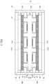
FIG. 8 is a schematic diagram of the first current collector of the lithium battery structure of this invention. - Please refer to
FIG. 1 , which is a schematic diagram of the lithium battery structure of this invention. The lithium battery structure includes two battery units, i.e. afirst battery unit 10a and asecond battery unit 10b. Thefirst battery units 10a includes a firstcurrent collector 21, a firstactive material layer 22, aseparator 23, a secondactive material layer 24 and a secondcurrent collector 25. Thesecond battery units 10b includes a firstcurrent collector 31, a firstactive material layer 32, aseparator 33, a secondactive material layer 34 and a secondcurrent collector 35. - First, the first
current collectors FIGs. 2A and 2B. FIG. 2A is a schematic diagram of the first current collector of the lithium battery structure of this invention.FIG. 2B is a cross-sectional view taken along line A-A ofFIG. 2A thereof. InFIGs. 2A and 2B , the firstcurrent collector 21 of thefirst battery unit 10a is illustrated. The firstcurrent collector 21 includes aconductive substrate 211 and anisolation layer 212. Theconductive substrate 211 is made of copper, nickel, iron, gold, zinc, silver, titanium or a combination thereof, or lithium-unalloyable materials. Theconductive substrate 211 has afirst surface 2112 and asecond surface 2113 opposite and parallel to thefirst surface 2112. Theconductive substrate 211 further includes a plurality of throughholes 2111, extended from thefirst surface 2112 to thesecond surface 2113. Theisolation layer 212 is disposed on thefirst surface 2112 of theconductive substrate 211 and covers the sidewalls of the throughholes 2111 to extend to the surface near to the edge of the openings of the throughholes 2111 on thesecond surface 2113. As showing inFIG. 2B , theisolation layer 212 is disposed on thefirst surface 2112 of theconductive substrate 211 and essentially covers completely thefirst surface 2112 and sidewalls of the throughholes 2111, and extends to cover parts, which is near to the opening of the throughholes 2111, of thesecond surface 2113 to form the firstcurrent collectors 21. - The
isolation layer - The first
active material layer 22 is disposed on an uncovered area by theisolation layer 212 of thesecond surface 2113 of the firstcurrent collector 21. Therefore, the firstactive material layer 22 is directly contacted to the firstcurrent collector 21, referring toFIG. 2C . Generally speaking, the firstactive material layer 22 is made of a negative material, such as a lithium metal or a lithium alloy, which is coated or pasting thereon. Moreover, the firstactive material layer 22 may be a carbon, a silicon oxide, or a combination thereof. The firstcurrent collector 31, which is composed of theconductive substrate 311 with a plurality of throughholes 3111 and theisolation layer 312, of thesecond battery unit 10b is the same as that of the previous embodiment for the firstcurrent collector 21 of thefirst battery unit 10a. Thus, a repeated description will be omitted. - As shown in
FIG. 1 , theseparator 23 is disposed on the firstcurrent collector 21 of thefirst battery unit 10a. The secondactive material layer 24 and the secondcurrent collector 25 are sequentially disposed thereon. Also, theseparator 33 is disposed below the firstcurrent collector 31 of thesecond battery unit 10b. The secondactive material layer 34 and the secondcurrent collector 35 are sequentially disposed thereon. Theion guiding layer 13 is disposed between the two firstcurrent collectors ion guiding layer 13 is further extended into the throughholes 2111 of the firstcurrent collector 21 of thefirst battery unit 10a, and the throughholes 3111 of the firstcurrent collector 31 of thesecond battery unit 10b. - The
ion guiding layer 13 may be essentially only made of an ion-transmission material, or may be made of an ion-transmission material and a base material capable of impregnating the ion-transmission material. - When the ion guiding layer 13(main part) is made of an ion-transmission material and a base material capable of impregnating the ion-transmission material. The ion-transmission material essentially is a liquid electrolyte, a gel electrolyte, an ionic liquid, an ionic liquid electrolyte, an adjusting material for contact surfaces (detailed description below) or a combination thereof. The above materials are belong to the deformable or impregnable materials. The
ion guiding layer 13 may also further include a few amount of oxide-based solid electrolyte. The "few amount" means that is much less than the main part in volume or mass, as will be described in more detail below. Thepackaging structure 12 is disposed between the secondcurrent collector 25 of thefirst battery unit 10a and the secondcurrent collector 35 of thesecond battery unit 10b to package the whole battery structure. - The arrangement of the
packaging structure 12 is varied depending on the formation of the firstcurrent collectors FIG. 1 , the firstcurrent collector 21 of thefirst battery unit 10a and the firstcurrent collector 31 of thesecond battery unit 10b are extended in both sides. Thepackaging structure 12 is divided into three segments, which are thefirst package body 121 located between the secondcurrent collector 25 and the firstcurrent collector 21 of thefirst battery unit 10a, thesecond package body 122 located between the firstcurrent collector 21 of thefirst battery unit 10a and the firstcurrent collector 31 of thesecond battery unit 10b, and thethird package body 123 located between the firstcurrent collector 31 and the secondcurrent collector 35 of thesecond battery unit 10b. Thefirst package body 121, thesecond package body 122 and thethird package body 123 are surrounding frame structure to seal the sides of thefirst battery unit 10a and thesecond battery unit 10b. Excepting for the above-mentioned single layer structure, in another embodiment of this invention, all thefirst package body 121, thesecond package body 122 and thethird package body 123 of thepackaging structure 12 are three-layered structure. Please refer toFIGs. 3 and4 , taking thefirst package body 121 as an example, thefirst package body 121 includes asilicone layer 1213 and two modifiedsilicone layers silicone layer 1213. The modifiedsilicone layers current collector 25, the firstcurrent collector 21 and thesilicone layer 1213. The interfacial tension and the polarity of silicone are modified thereby. Also, the overall appearance is more complete and the production yield is improved. Furthermore, the ability of blocking moisture infiltrating from thefirst package body 121. Internally, the silicone body can prevent the damage of polar solvents and plasticizers, and the overall package structure is more complete. Thesecond package body 122 and thethird package body 123 are the same as that of the previous embodiment for thefirst package body 121. Thus, a repeated description will be omitted. - Please refer to
FIG. 5 , there may have anouter packaging structure 15 outside thepackaging structure 12. By this dual-frame structure, the ability of blocking moisture and oxygen for the lithium battery structure is better. Theouter packaging structure 15 may have the same or different materials or arrangement with thepackaging structure 12. - Please refer to
FIG. 1 , thefirst battery unit 10a and thesecond battery unit 10b are essentially face-to-face disposed to each other by the first active material layers 22, 32. In other word, the uncovered area, by theisolation layer 212, of the firstcurrent collector 21 of thefirst battery unit 10a is faced to the uncovered area, by theisolation layer 312, of the firstcurrent collector 31 of thesecond battery unit 10b. Generally speaking, in the case of lithium batteries, the firstactive material layer current collector active material layer current collector current collectors first battery unit 10a and thesecond battery unit 10b are face-to-face disposed to each other by the first active material layers 22, 32. Therefore, the lithium dendrites are limited to be plated between the first active material layers 22, 32 to avoid the plated lithium dendrite penetrating through theseparator - In this embodiment, the distance between the first
active material layer 22 of thefirst battery unit 10a and the firstactive material layer 32 of thesecond battery unit 10b is 5-100 micrometer. - Moreover, by the characteristic of the electrical insulation of the isolation layers 212, 312, the lithium ions would not deposit centrally close to the openings of the through holes during the electrical-chemical reaction of the battery. Accordingly, the lithium dendrites are not formed inside the through
holes separators - The base material of the
ion guiding layer 13 is porous and capable of impregnating the ion-transmission material. The base material is made of a polymer material, a ceramic material, a glass material, fiber material or a combination thereof. Also, the base material is porous via the particle materials stacking or the fiber materials crossing to form the pores. The particle materials include ceramic particles, polymer particles or glass particles. The fiber materials include polymer fibers or glass fibers. - The surfaces of the particle materials or the fiber materials are treated to have either negative or positive surface charges. For example, when the surfaces of the pores have positive surface charges, the electric double layer effect is reduced and the polarization of lithium ion migration is also reduced. When the surfaces of the pores have negative surface charges, the distribution of the lithium ions is more uniform.
- Due to the material has pores formed by the particle materials or the fiber materials, the lithium dendrite plates and strips inside the pores of the base material. During plating, the lithium dendrite attaches to the particles or the fibers to enhance the strength of the solid electrolyte interface (SEI). Comparing to the SEI's thickness, around 10-50 nanometers, the volume changes of plating/stripping, 15-20 microns, of the lithium dendrites are too violent and the SEI will be seriously damaged during plating and/or stripping of the lithium dendrite without providing the supporting. The lithium ion concentration would be consumed and lead to the reversible capacity loss of the battery. Therefore, the particle materials or the fiber materials structure of the base material can provide supporting for the SEI to decrease the capacity loss of the battery. Under certain conditions, parts of the particle materials or the fiber materials may react with the reaction of forming the SEI. Therefore, the continuous forming of the SEI is reduced to decrease the capacity loss of the battery.
- Moreover, by the surface tension of the particle materials or the fiber materials structure of the base material, the electrolyte is continuously and uniformly guided to the first active material layers 22, 32 to improve the efficiency of the ion exchange. The surfaces of the particle materials or the fiber materials are treated to have either negative or positive surface charges to make the distribution of the electrolyte be more uniform. When the surfaces of the pores have positive surface charges, the polarization of lithium ion migration is reduced. When the surfaces of the pores have negative surface charges, the distribution of the lithium ions is more uniform, and the lithium dendrites are tended to undirected growth.
- Furthermore, it is considered that the material of the
ion guiding layer 13 is essentially an insulating material, which can prevent the short circuit between the positive and negative current collectors from contacting each other. Theseparators FIG. 6 . - Then, the following embodiment is related to the
ion guiding layer 13, which only made of an ion-transmission material.FIG. 7 is a schematic diagram of the lithium battery structure of this invention. Since some components ofFIG. 7 are the same as those of the above-described example embodiments inFIG. 1 , a repeated description thereof will be omitted. The main difference betweenFIG. 1 andFIG. 7 is the ion guiding layer does not contain the above mentioned base material. The main body of the ion-transmission material is the inorganic solid electrolyte, such as an oxide-based solid electrolyte or a sulfide-based solid electrolyte, with poor deformation ability, i.e. better stress tolerance. This ion guiding layer is labeled as the inorganicsolid electrolyte layer 14 in theFIG. 7 . Also, the outer surfaces of the firstcurrent collectors separators solid electrolyte layer 14 may further include a few amount of a liquid electrolyte, a gel electrolyte, an ionic liquid, an ionic liquid electrolyte or a combination thereof. The electrolyte may be distributed more uniform and the problem of the high interface resistances between the inorganic solid electrolytes can be solved. Also, inFIG. 7 , thefirst package body 121, thesecond package body 122 and thethird package body 123 of thepackaging structure 12 may be single layer or three-layered structure. Since these components ofFIG. 7 are the same as those of the above-described example embodiments inFIG. 4 , a repeated description thereof will be omitted. - When the problems of the high interface resistances caused by the poor contact between the inorganic solid electrolytes are considered, an adjusting material for contact surfaces may be coated on the inorganic solid electrolyte particles, or disposed between the inorganic solid electrolytes. Therefore, a surface to surface ion transfer path between the inorganic solid electrolytes would be formed by the adjusting material. The adjusting material is mainly composed of a polymer substrate capable of transmitting lithium ions inside the material and an additive material capable of dissociating the lithium salt and being used as a plasticizer.
- The polymer substrate capable of transmitting lithium ions inside the material means that the material does not contain lithium ions of the material itself or during the beginning of the electrochemical reaction, but the lithium ions can be transferred. For example, the polymer substrate may be linear structure material without salts, such as PEO. Also, excepting for transferring the lithium ions, the polymer substrate may be cross-linked structure to enhance mechanical strength of the film formed by the polymer substrate. The polymer substrate with cross-linked structure may be poly(ethylene glycol)diacrylate (PEGDA), poly(ethylene glycol)dimethacrylate (PEGDMA), poly(ethylene glycol) monomethylether (PEGME), poly(ethylene glycol) dimethylether (PEGDME), poly[ethylene oxide-co-2-(2-methoxyethoxy)ethyl glycidyl ether] (PEO/MEEGE), or hyperbranched polymers, such as poly[bis(triethylene glycol)benzoate, or polynitriles, such as polyacrylonitrile (PAN), poly(methacrylonitrile) (PMAN), poly(N-2-cyanoethyl)ethyleneamine) (PCEEI).
- On the other hand, the adjusting material may further mix with a crystallization inhibition material and an ion supply material. The ion supply material may be a lithium salt, such as LiTFSI, LiFSI, LiBF4, LiPF6, to increase the concentration of the lithium ions. The crystallization inhibition material is used to reduce the crystallinity, such as poly(ethyl methacrylate) (PEMA), poly(methyl methacrylate) (PMMA), poly(oxyethylene), poly (cyanoacrylate) (PCA), polyethylene glycol (PEG), poly(vinyl alcohol) (PVA), polyvinyl butyral (PVB), poly(vinyl chloride) (PVC), PVC-PEMA, PEO-PMMA, poly(acrylonitrile-co-methyl methacrylate) (P(AN-co-MMA)), PVA-PVdF, PAN-PVA, PVC-PEMA, polycarbonates, such as poly(ethylene oxide-co-ethylene carbonate) (PEOEC), polyhedral oligomeric silsesquioxane (POSS), polyethylene carbonate (PEC), poly (propylene carbonate) (PPC), poly(ethyl glycidyl ether carbonate) (P(Et-GEC)), poly(t-butyl glycidyl ether carbonate)( P(tBu-GEC)), cyclic carbonates, such as poly (trimethylene carbonate) (PTMC), polysiloxane-based, such as polydimethylsiloxane (PDMS), poly(dimethyl siloxane-co-ethylene oxide) (P(DMS-co-EO)), poly(siloxane-g-ethyleneoxide), polyesters, such as ethylene adipate, ethylene succinate, ethylene malonate. Furthermore, it may also be poly(vinylidenedifluoridehexafluoropropylene) (PvdF-HFP), poly(vinylidenedifluoride) (PvdF), or poly(ε-caprolactone) (PCL).
- The additive material is served as a plasticizer and dissociates the lithium salt, which may be plastic crystal electrolytes (PCEs), such as succinonitrile (SN) [ETPTA//SN; PEO/SN; PAN/PVA-CN/SN]), N-ethyl-N-methylpyrrolidinium, [C2mpyr] + AnionsN, N-diethyl-pyrrolidinium,[C2epyr], quaternary alkylammonium, n-alkyltrimethylphosphonium, [P1,1,1,n], decamethylferro-cenium, [Fe(C5Me5)2]), 1-(N,N-dimethylammonium)-2-(ammonium)ethane triflate ([DMEDAH2] [Tf]2, Anions=[FSI], [FSA], [CFSA], [BETA]), LiSi(CH3)3SO4, trimethy(lithium trimethylsilyl sulfate), or ionic liquid, may be imidazolium, such as anion/bis(trifluoromethanesulfonyl)imide), anion/bis(fluorosulfonyl)imide, anion/trifluoromethanesulfonate, or ammonium, such as anion/bis(trifluoromethanesulfonyl)imide, or pyrrolidinium, such as anion/bis(trifluoromethanesulfonyl)imide, anion/bis(fluorosulfonyl)imide, or piperidinium, such as anion/bis(trifluoromethanesulfonyl)imide, anion/bis(fluorosulfonyl)imide.
- The adjusting material may further mix with the second additive, such as a nanoscale inactive ceramic material (non-electrolyte oxide), a nanoscale inorganic solid electrolyte, or a conductive material. When the second additive is the inactive ceramic material, the used amount of the polymer substrate and the additive can be reduced. Further, the film-forming ability of the adjusting material is improved and the inactive ceramic material is used as a film -reinforcement material. The material may be the silicon dioxide. When the second additive is the nanoscale inorganic solid electrolyte, the used amount of the polymer substrate and the additive can be reduced and a high rate ion transfer path is provided. The inorganic solid electrolyte may be an oxide-based solid electrolyte, a sulfide-based solid electrolyte or any other inorganic solid electrolyte. For example, when the ion transfer is occurred in the adjusting material, the ions may be transmitted via the adjusting material, or via the nanoscale inorganic solid electrolyte once contacting the nanoscale inorganic solid electrolyte.
- Moreover, the content of the adjusting material is higher when close to the first and the second
active material layer - Also, when the ion guiding layer is composed of the ion-transmission material only, the ion-transmission material may be composed of the above mentioned adjusting material and the an ion supply material, or further mix with the crystallization inhibition material.
- For clearly describing the face-to-face arrangement of the first active material layers 22 of the
first battery unit 10a and the first active material layers 32 of thesecond battery unit 10b, please refer toFIGs. 8 and2B .FIG. 8 is a schematic diagram of the first current collector of the lithium battery structure of this invention. Theisolation layer 212 is disposed to completely cover thefirst surface 2112, and extend along the sidewalls of the throughholes 2111 to the edge of the openings of the throughholes 2111 on thesecond surface 2113. Therefore, the uncovered area of thesecond surface 2113, by theisolation layer 212, of the firstcurrent collector 21 are the regions outside the edge of the openings of the throughholes 2111 on thesecond surface 2113. The firstactive material layer 22 is disposed on this area. The first active material layers 22 of thefirst battery unit 10a and the first active material layers 32 of thesecond battery unit 10b are disposed face-to-face to control the lithium dendrites plated therebetween. Therefore, the face-to-face arrangement make the lithium dendrites tend to plate between the first active material layers 22, 32. The invention is not limited that the distribution and the arrangement of the first active material layers 22 of thefirst battery unit 10a and the first active material layers 32 of thesecond battery unit 10b have to be the same. The relative location, the distribution or the patterns may be modified or varied. The control for growth trend of the lithium dendrites is still achieved. - Accordingly, in this invention, the two negative active material layers are disposed in face-to-face arrangement to effectively control the locations of the plated lithium dendrites. Therefore, the safety of the battery and the cycle life of the battery is greatly improved.
Claims (19)
- A lithium battery structure, comprising:a first and a second battery units, each of the battery units including a first current collector, a first active material layer, a second active material layer and a second current collector, wherein the first current collector comprising:a conductive substrate, having a first surface, a second surface opposite and parallel to the first surface and a plurality of through holes extended from the first surface to the second surface; andan isolation layer, disposed on the first surface of the conductive substrate and essentially covering completely the first surface and sidewalls of the through holes, and extending to cover parts of the second surface;wherein the first active material layer is disposed on an uncovered area of the second surface, and the second active material layer and the second current collector sequentially disposed on the first surface of the conductive substrate completely covered by the isolation layer;wherein the first and the second battery units are essentially face-to-face disposed to each other by the first active material layers;an ion guiding layer, disposed between the first active material layers of the first and the second battery units and extending to the through holes; anda packaging structure, disposed between the second current collectors of the first and the second battery units to package the first and the second battery units.
- The lithium battery structure of claim 1, wherein a material of the isolation layer is insulation polymer material, insulation ceramic material, insulation glass material, insulation glass fiber material or a combination thereof.
- The lithium battery structure of claim 2, wherein the insulation polymer material includes polyimide, polyethylene terephthalate, polyurethane, polyacrylate, epoxy and silicone, and the insulation glass fiber material includes FR4-class epoxy glass fiber material.
- The lithium battery structure of claim 1, wherein a distance between the first active material layers of the first and the second battery units is 5-100 micrometer.
- The lithium battery structure of claim 1, wherein the ion guiding layer is made of an ion-transmission material and a base material capable of impregnating the ion-transmission material.
- The lithium battery structure of claim 5, wherein the base material is porous and made of a polymer material, a ceramic material, a glass material, fiber material or a combination thereof.
- The lithium battery structure of claim 6, wherein the base material is porous via a particle or a fiber material.
- The lithium battery structure of claim 5, wherein the ion-transmission material is a liquid electrolyte, a gel electrolyte, an ionic liquid, an ionic liquid electrolyte or a combination thereof.
- The lithium battery structure of claim 5, wherein the ion-transmission material is made of an adjusting material for contact surfaces and a dissociable lithium salt, and the adjusting material is mainly composed of a polymer substrate capable of transmitting metallic ions inside the material and an additive material capable of dissociating the lithium salt and being served as a plasticizer.
- The lithium battery structure of claim 9, wherein the adjusting material further includes a crystallization inhibition material.
- The lithium battery structure of claim 1, wherein the first and the second battery units further include a separator respectively, and the separator is disposed between the second active material layer and the first current collector.
- The lithium battery structure of claim 1, wherein the ion guiding layer is essentially only made of an ion-transmission material.
- The lithium battery structure of claim 12, wherein the ion-transmission material is an inorganic solid electrolyte.
- The lithium battery structure of claim 13, wherein the ion-transmission material further includes a liquid electrolyte, a gel electrolyte, an ionic liquid, an ionic liquid electrolyte or a combination thereof.
- The lithium battery structure of claim 13, wherein the ion-transmission material further includes an adjusting material for contact surfaces, and the adjusting material is mainly composed of a polymer substrate capable of transmitting metallic ions inside the material and an additive material capable of dissociating the lithium salt and being served as a plasticizer.
- The lithium battery structure of claim 15, wherein the adjusting material further includes a crystallization inhibition material.
- The lithium battery structure of claim 15, wherein the adjusting material further includes an ion supply material.
- The lithium battery structure of claim 12, wherein the ion-transmission material is made of an adjusting material for contact surfaces and a dissociable lithium salt, and the adjusting material is mainly composed of a polymer substrate capable of transmitting metallic ions inside the material and an additive material capable of dissociating the lithium salt and being served as a plasticizer.
- The lithium battery structure of claim 18, wherein the adjusting material further includes a crystallization inhibition material.
Applications Claiming Priority (1)
| Application Number | Priority Date | Filing Date | Title |
|---|---|---|---|
| US16/677,977 US11881560B2 (en) | 2016-10-12 | 2019-11-08 | Lithium battery structure and electrode layer thereof |
Publications (3)
| Publication Number | Publication Date |
|---|---|
| EP3819960A1 EP3819960A1 (en) | 2021-05-12 |
| EP3819960B1 true EP3819960B1 (en) | 2023-12-06 |
| EP3819960C0 EP3819960C0 (en) | 2023-12-06 |
Family
ID=68965683
Family Applications (1)
| Application Number | Title | Priority Date | Filing Date |
|---|---|---|---|
| EP19217650.1A Active EP3819960B1 (en) | 2019-11-08 | 2019-12-18 | Lithium battery structure and electrode layer thereof |
Country Status (7)
| Country | Link |
|---|---|
| EP (1) | EP3819960B1 (en) |
| JP (1) | JP7086120B2 (en) |
| KR (1) | KR102315183B1 (en) |
| CN (1) | CN112786969B (en) |
| ES (1) | ES2966546T3 (en) |
| MX (1) | MX2020001611A (en) |
| RU (1) | RU2727523C1 (en) |
Families Citing this family (5)
| Publication number | Priority date | Publication date | Assignee | Title |
|---|---|---|---|---|
| CN113328211B (en) * | 2021-05-27 | 2022-09-27 | 贵州梅岭电源有限公司 | High-energy-density lithium primary battery negative plate and preparation method thereof |
| CN113328210B (en) * | 2021-05-27 | 2022-09-27 | 贵州梅岭电源有限公司 | Lithium metal negative plate of lithium battery and preparation method thereof |
| TWI762418B (en) | 2021-09-03 | 2022-04-21 | 輝能科技股份有限公司 | Lithium electrode |
| CN115832640A (en) * | 2021-11-22 | 2023-03-21 | 宁德时代新能源科技股份有限公司 | Negative electrode sheet and its preparation method, secondary battery and its preparation method, battery module, battery pack and electrical device |
| EP4407719A4 (en) * | 2022-05-07 | 2025-07-30 | Contemporary Amperex Technology Hong Kong Ltd | NEGATIVE POLE PIECE, ELECTRODE ASSEMBLY, BATTERY CELL, BATTERY AND ELECTRICAL DEVICE |
Family Cites Families (21)
| Publication number | Priority date | Publication date | Assignee | Title |
|---|---|---|---|---|
| JPH0636800A (en) * | 1992-07-17 | 1994-02-10 | Mitsubishi Cable Ind Ltd | Lithium secondary battery |
| JP3831525B2 (en) * | 1998-06-30 | 2006-10-11 | 三洋電機株式会社 | battery |
| US7993782B2 (en) * | 2005-07-01 | 2011-08-09 | National Institute For Materials Science | All-solid lithium battery |
| FR2899235B1 (en) * | 2006-03-31 | 2012-10-05 | Arkema | SOLID POLYMER ELECTROLYTES BASED ON TRIBLOC COPOLYMERS, IN PARTICULAR POLYSTYRENE-POLY (OXYETHYLENE) -POLYSTYRENE |
| CZ301387B6 (en) * | 2008-09-19 | 2010-02-10 | He3Da S.R.O. | Lithium battery with spatial electrode type and method of production |
| RU2513988C2 (en) * | 2009-05-26 | 2014-04-27 | Оптодот Корпорейшн | Battery having electrodes in form of coating deposited directly on nanoporous separators |
| JP5644858B2 (en) * | 2010-08-09 | 2014-12-24 | 株式会社村田製作所 | Stacked solid battery |
| JP6565000B2 (en) * | 2014-01-15 | 2019-08-28 | パナソニックIpマネジメント株式会社 | Method for manufacturing electrochemical device |
| KR102207927B1 (en) * | 2014-07-14 | 2021-01-26 | 삼성전자주식회사 | Electrolyte, lithium battery and lithium metal battery including the same, and method for preparation the electrolyte |
| TWI563716B (en) * | 2014-07-16 | 2016-12-21 | Prologium Technology Co Ltd | Anode electrode |
| KR102490865B1 (en) * | 2015-06-18 | 2023-01-20 | 삼성에스디아이 주식회사 | Electrode assembly and lithium battery including the same |
| CN106328955B (en) * | 2015-06-25 | 2019-02-12 | 清华大学 | Lithium-air battery cathode and lithium-air battery |
| US9735412B2 (en) * | 2015-09-25 | 2017-08-15 | Intel Corporation | Rechargeable battery and method to suppress dendrite |
| CN107681190B (en) * | 2016-08-01 | 2019-11-05 | 北京好风光储能技术有限公司 | A kind of the bipolar structure body and battery core of high-voltage battery |
| ES2873258T3 (en) * | 2016-10-12 | 2021-11-03 | Prologium Tech Co Ltd | Lithium metal electrode and its associated lithium metal battery |
| US20180102547A1 (en) * | 2016-10-12 | 2018-04-12 | Prologium Technology Co., Ltd. | Current Collector |
| JP7117658B2 (en) * | 2017-05-29 | 2022-08-15 | パナソニックIpマネジメント株式会社 | Lithium metal secondary battery |
| WO2019071184A1 (en) * | 2017-10-06 | 2019-04-11 | Johnson Controls Technology Company | Lithium ion battery |
| KR102518686B1 (en) * | 2017-10-31 | 2023-04-05 | 현대자동차주식회사 | All-solid battery and method for manufacturing the same |
| KR20190056848A (en) * | 2017-11-17 | 2019-05-27 | 주식회사 엘지화학 | Electrode assembly |
| KR102047300B1 (en) * | 2017-12-27 | 2019-11-21 | 청주대학교 산학협력단 | Hybrid solid electrolyte and secondary battery using the same |
-
2019
- 2019-12-16 CN CN201911293796.3A patent/CN112786969B/en active Active
- 2019-12-18 EP EP19217650.1A patent/EP3819960B1/en active Active
- 2019-12-18 ES ES19217650T patent/ES2966546T3/en active Active
-
2020
- 2020-01-21 KR KR1020200007901A patent/KR102315183B1/en active Active
- 2020-01-25 RU RU2020103058A patent/RU2727523C1/en active
- 2020-02-03 JP JP2020016234A patent/JP7086120B2/en active Active
- 2020-02-10 MX MX2020001611A patent/MX2020001611A/en unknown
Also Published As
| Publication number | Publication date |
|---|---|
| MX2020001611A (en) | 2021-05-10 |
| RU2727523C1 (en) | 2020-07-22 |
| CN112786969B (en) | 2023-08-29 |
| KR20210056881A (en) | 2021-05-20 |
| KR102315183B1 (en) | 2021-10-20 |
| JP7086120B2 (en) | 2022-06-17 |
| JP2021077611A (en) | 2021-05-20 |
| BR102020002828A2 (en) | 2021-05-18 |
| EP3819960A1 (en) | 2021-05-12 |
| EP3819960C0 (en) | 2023-12-06 |
| ES2966546T3 (en) | 2024-04-22 |
| CN112786969A (en) | 2021-05-11 |
Similar Documents
| Publication | Publication Date | Title |
|---|---|---|
| EP3819960B1 (en) | Lithium battery structure and electrode layer thereof | |
| US12272796B2 (en) | Lithium battery structure and electrode layer thereof | |
| CN102088110B (en) | Lithium secondary battery | |
| JP7037509B2 (en) | Lithium battery manufacturing method | |
| US12412903B1 (en) | Metallized current collector for stacked battery | |
| US20210320382A1 (en) | Composite separating layer | |
| CN110635107A (en) | Substrate-free bipolar solid-state lithium-ion battery and manufacturing method thereof | |
| JP2024544468A (en) | Lithium ion conductive separator membrane | |
| US20250132376A1 (en) | Lithium-ion secondary battery and negative electrode structure | |
| CN119381397A (en) | A double electrode plate for a solid-state lithium metal battery and a method for preparing the same | |
| JP7847593B2 (en) | Coated three-dimensional electronically conductive network for use as an electrode | |
| CN114530670B (en) | Battery cell structure and secondary battery | |
| TWI725654B (en) | Lithium battery structure and electrode layer thereof | |
| EP4730471A1 (en) | Lithium-ion secondary battery, positive electrode structure thereof, and charging and discharging method therefor | |
| US11862802B2 (en) | Lithium electrode | |
| BR102020002828B1 (en) | Lithium battery structure and its electrode layer. | |
| CN119786697B (en) | Secondary battery and preparation method thereof, and electronic device | |
| EP4730470A1 (en) | Lithium-ion secondary battery and negative electrode structure | |
| KR102599352B1 (en) | Anode laminate comprising protecting layer with engraved pattern, lithium secondary battery comprising same and method for manufacturing same | |
| US20250070267A1 (en) | Energy storage cell and method for preparing energy storage cell | |
| US20250023176A1 (en) | Secondary battery module | |
| KR20260048684A (en) | Stacked thi film all solid state battery module and manufacturing method thereof | |
| HK40105869A (en) | Lithium-ion conducting separator membrane | |
| CN118899549A (en) | A laminated structure and battery | |
| BR102022015974B1 (en) | LITHIUM ELECTRODE |
Legal Events
| Date | Code | Title | Description |
|---|---|---|---|
| PUAI | Public reference made under article 153(3) epc to a published international application that has entered the european phase |
Free format text: ORIGINAL CODE: 0009012 |
|
| STAA | Information on the status of an ep patent application or granted ep patent |
Free format text: STATUS: THE APPLICATION HAS BEEN PUBLISHED |
|
| AK | Designated contracting states |
Kind code of ref document: A1 Designated state(s): AL AT BE BG CH CY CZ DE DK EE ES FI FR GB GR HR HU IE IS IT LI LT LU LV MC MK MT NL NO PL PT RO RS SE SI SK SM TR |
|
| STAA | Information on the status of an ep patent application or granted ep patent |
Free format text: STATUS: REQUEST FOR EXAMINATION WAS MADE |
|
| 17P | Request for examination filed |
Effective date: 20211112 |
|
| RBV | Designated contracting states (corrected) |
Designated state(s): AL AT BE BG CH CY CZ DE DK EE ES FI FR GB GR HR HU IE IS IT LI LT LU LV MC MK MT NL NO PL PT RO RS SE SI SK SM TR |
|
| REG | Reference to a national code |
Ref country code: DE Ref legal event code: R079 Free format text: PREVIOUS MAIN CLASS: H01M0002020000 Ipc: H01M0004134000 Ref document number: 602019042739 Country of ref document: DE |
|
| GRAP | Despatch of communication of intention to grant a patent |
Free format text: ORIGINAL CODE: EPIDOSNIGR1 |
|
| STAA | Information on the status of an ep patent application or granted ep patent |
Free format text: STATUS: GRANT OF PATENT IS INTENDED |
|
| INTG | Intention to grant announced |
Effective date: 20230622 |
|
| RIC1 | Information provided on ipc code assigned before grant |
Ipc: H01M 50/124 20210101ALI20230609BHEP Ipc: H01M 50/121 20210101ALI20230609BHEP Ipc: H01M 50/105 20210101ALI20230609BHEP Ipc: H01M 10/0585 20100101ALI20230609BHEP Ipc: H01M 10/056 20100101ALI20230609BHEP Ipc: H01M 10/052 20100101ALI20230609BHEP Ipc: H01M 4/80 20060101ALI20230609BHEP Ipc: H01M 4/74 20060101ALI20230609BHEP Ipc: H01M 4/70 20060101ALI20230609BHEP Ipc: H01M 4/66 20060101ALI20230609BHEP Ipc: H01M 4/38 20060101ALI20230609BHEP Ipc: H01M 4/134 20100101AFI20230609BHEP |
|
| GRAS | Grant fee paid |
Free format text: ORIGINAL CODE: EPIDOSNIGR3 |
|
| GRAA | (expected) grant |
Free format text: ORIGINAL CODE: 0009210 |
|
| STAA | Information on the status of an ep patent application or granted ep patent |
Free format text: STATUS: THE PATENT HAS BEEN GRANTED |
|
| AK | Designated contracting states |
Kind code of ref document: B1 Designated state(s): AL AT BE BG CH CY CZ DE DK EE ES FI FR GB GR HR HU IE IS IT LI LT LU LV MC MK MT NL NO PL PT RO RS SE SI SK SM TR |
|
| REG | Reference to a national code |
Ref country code: GB Ref legal event code: FG4D |
|
| REG | Reference to a national code |
Ref country code: CH Ref legal event code: EP |
|
| REG | Reference to a national code |
Ref country code: DE Ref legal event code: R096 Ref document number: 602019042739 Country of ref document: DE |
|
| REG | Reference to a national code |
Ref country code: IE Ref legal event code: FG4D |
|
| U01 | Request for unitary effect filed |
Effective date: 20231222 |
|
| U07 | Unitary effect registered |
Designated state(s): AT BE BG DE DK EE FI FR IT LT LU LV MT NL PT SE SI Effective date: 20240109 |
|
| U20 | Renewal fee for the european patent with unitary effect paid |
Year of fee payment: 5 Effective date: 20240206 |
|
| PG25 | Lapsed in a contracting state [announced via postgrant information from national office to epo] |
Ref country code: GR Free format text: LAPSE BECAUSE OF FAILURE TO SUBMIT A TRANSLATION OF THE DESCRIPTION OR TO PAY THE FEE WITHIN THE PRESCRIBED TIME-LIMIT Effective date: 20240307 |
|
| REG | Reference to a national code |
Ref country code: ES Ref legal event code: FG2A Ref document number: 2966546 Country of ref document: ES Kind code of ref document: T3 Effective date: 20240422 |
|
| PG25 | Lapsed in a contracting state [announced via postgrant information from national office to epo] |
Ref country code: GR Free format text: LAPSE BECAUSE OF FAILURE TO SUBMIT A TRANSLATION OF THE DESCRIPTION OR TO PAY THE FEE WITHIN THE PRESCRIBED TIME-LIMIT Effective date: 20240307 |
|
| PG25 | Lapsed in a contracting state [announced via postgrant information from national office to epo] |
Ref country code: RS Free format text: LAPSE BECAUSE OF FAILURE TO SUBMIT A TRANSLATION OF THE DESCRIPTION OR TO PAY THE FEE WITHIN THE PRESCRIBED TIME-LIMIT Effective date: 20231206 Ref country code: NO Free format text: LAPSE BECAUSE OF FAILURE TO SUBMIT A TRANSLATION OF THE DESCRIPTION OR TO PAY THE FEE WITHIN THE PRESCRIBED TIME-LIMIT Effective date: 20240306 Ref country code: HR Free format text: LAPSE BECAUSE OF FAILURE TO SUBMIT A TRANSLATION OF THE DESCRIPTION OR TO PAY THE FEE WITHIN THE PRESCRIBED TIME-LIMIT Effective date: 20231206 |
|
| PG25 | Lapsed in a contracting state [announced via postgrant information from national office to epo] |
Ref country code: IS Free format text: LAPSE BECAUSE OF FAILURE TO SUBMIT A TRANSLATION OF THE DESCRIPTION OR TO PAY THE FEE WITHIN THE PRESCRIBED TIME-LIMIT Effective date: 20240406 |
|
| PG25 | Lapsed in a contracting state [announced via postgrant information from national office to epo] |
Ref country code: CZ Free format text: LAPSE BECAUSE OF FAILURE TO SUBMIT A TRANSLATION OF THE DESCRIPTION OR TO PAY THE FEE WITHIN THE PRESCRIBED TIME-LIMIT Effective date: 20231206 |
|
| PG25 | Lapsed in a contracting state [announced via postgrant information from national office to epo] |
Ref country code: SK Free format text: LAPSE BECAUSE OF FAILURE TO SUBMIT A TRANSLATION OF THE DESCRIPTION OR TO PAY THE FEE WITHIN THE PRESCRIBED TIME-LIMIT Effective date: 20231206 |
|
| PG25 | Lapsed in a contracting state [announced via postgrant information from national office to epo] |
Ref country code: SM Free format text: LAPSE BECAUSE OF FAILURE TO SUBMIT A TRANSLATION OF THE DESCRIPTION OR TO PAY THE FEE WITHIN THE PRESCRIBED TIME-LIMIT Effective date: 20231206 Ref country code: SK Free format text: LAPSE BECAUSE OF FAILURE TO SUBMIT A TRANSLATION OF THE DESCRIPTION OR TO PAY THE FEE WITHIN THE PRESCRIBED TIME-LIMIT Effective date: 20231206 Ref country code: RO Free format text: LAPSE BECAUSE OF FAILURE TO SUBMIT A TRANSLATION OF THE DESCRIPTION OR TO PAY THE FEE WITHIN THE PRESCRIBED TIME-LIMIT Effective date: 20231206 Ref country code: IS Free format text: LAPSE BECAUSE OF FAILURE TO SUBMIT A TRANSLATION OF THE DESCRIPTION OR TO PAY THE FEE WITHIN THE PRESCRIBED TIME-LIMIT Effective date: 20240406 Ref country code: CZ Free format text: LAPSE BECAUSE OF FAILURE TO SUBMIT A TRANSLATION OF THE DESCRIPTION OR TO PAY THE FEE WITHIN THE PRESCRIBED TIME-LIMIT Effective date: 20231206 |
|
| REG | Reference to a national code |
Ref country code: CH Ref legal event code: PL |
|
| PG25 | Lapsed in a contracting state [announced via postgrant information from national office to epo] |
Ref country code: PL Free format text: LAPSE BECAUSE OF FAILURE TO SUBMIT A TRANSLATION OF THE DESCRIPTION OR TO PAY THE FEE WITHIN THE PRESCRIBED TIME-LIMIT Effective date: 20231206 |
|
| PG25 | Lapsed in a contracting state [announced via postgrant information from national office to epo] |
Ref country code: PL Free format text: LAPSE BECAUSE OF FAILURE TO SUBMIT A TRANSLATION OF THE DESCRIPTION OR TO PAY THE FEE WITHIN THE PRESCRIBED TIME-LIMIT Effective date: 20231206 |
|
| REG | Reference to a national code |
Ref country code: DE Ref legal event code: R097 Ref document number: 602019042739 Country of ref document: DE |
|
| PG25 | Lapsed in a contracting state [announced via postgrant information from national office to epo] |
Ref country code: MC Free format text: LAPSE BECAUSE OF FAILURE TO SUBMIT A TRANSLATION OF THE DESCRIPTION OR TO PAY THE FEE WITHIN THE PRESCRIBED TIME-LIMIT Effective date: 20231206 |
|
| REG | Reference to a national code |
Ref country code: IE Ref legal event code: MM4A |
|
| PG25 | Lapsed in a contracting state [announced via postgrant information from national office to epo] |
Ref country code: IE Free format text: LAPSE BECAUSE OF NON-PAYMENT OF DUE FEES Effective date: 20231218 |
|
| PLBE | No opposition filed within time limit |
Free format text: ORIGINAL CODE: 0009261 |
|
| STAA | Information on the status of an ep patent application or granted ep patent |
Free format text: STATUS: NO OPPOSITION FILED WITHIN TIME LIMIT |
|
| PG25 | Lapsed in a contracting state [announced via postgrant information from national office to epo] |
Ref country code: CH Free format text: LAPSE BECAUSE OF NON-PAYMENT OF DUE FEES Effective date: 20231231 |
|
| PG25 | Lapsed in a contracting state [announced via postgrant information from national office to epo] |
Ref country code: IE Free format text: LAPSE BECAUSE OF NON-PAYMENT OF DUE FEES Effective date: 20231218 Ref country code: CH Free format text: LAPSE BECAUSE OF NON-PAYMENT OF DUE FEES Effective date: 20231231 |
|
| 26N | No opposition filed |
Effective date: 20240909 |
|
| U20 | Renewal fee for the european patent with unitary effect paid |
Year of fee payment: 6 Effective date: 20241226 |
|
| PG25 | Lapsed in a contracting state [announced via postgrant information from national office to epo] |
Ref country code: CY Free format text: LAPSE BECAUSE OF FAILURE TO SUBMIT A TRANSLATION OF THE DESCRIPTION OR TO PAY THE FEE WITHIN THE PRESCRIBED TIME-LIMIT; INVALID AB INITIO Effective date: 20191218 |
|
| PG25 | Lapsed in a contracting state [announced via postgrant information from national office to epo] |
Ref country code: HU Free format text: LAPSE BECAUSE OF FAILURE TO SUBMIT A TRANSLATION OF THE DESCRIPTION OR TO PAY THE FEE WITHIN THE PRESCRIBED TIME-LIMIT; INVALID AB INITIO Effective date: 20191218 |
|
| PG25 | Lapsed in a contracting state [announced via postgrant information from national office to epo] |
Ref country code: TR Free format text: LAPSE BECAUSE OF FAILURE TO SUBMIT A TRANSLATION OF THE DESCRIPTION OR TO PAY THE FEE WITHIN THE PRESCRIBED TIME-LIMIT Effective date: 20231206 |
|
| PGFP | Annual fee paid to national office [announced via postgrant information from national office to epo] |
Ref country code: GB Payment date: 20251208 Year of fee payment: 7 |
|
| U20 | Renewal fee for the european patent with unitary effect paid |
Year of fee payment: 7 Effective date: 20251230 |
|
| PGFP | Annual fee paid to national office [announced via postgrant information from national office to epo] |
Ref country code: ES Payment date: 20260107 Year of fee payment: 7 |