EP3819615A1 - Ir pixel reconfigurable in di or bdi mode - Google Patents
Ir pixel reconfigurable in di or bdi mode Download PDFInfo
- Publication number
- EP3819615A1 EP3819615A1 EP20204422.8A EP20204422A EP3819615A1 EP 3819615 A1 EP3819615 A1 EP 3819615A1 EP 20204422 A EP20204422 A EP 20204422A EP 3819615 A1 EP3819615 A1 EP 3819615A1
- Authority
- EP
- European Patent Office
- Prior art keywords
- transistor
- polarization
- mode
- bias
- stage
- Prior art date
- Legal status (The legal status is an assumption and is not a legal conclusion. Google has not performed a legal analysis and makes no representation as to the accuracy of the status listed.)
- Pending
Links
- 230000010287 polarization Effects 0.000 claims abstract description 72
- 238000002347 injection Methods 0.000 claims abstract description 35
- 239000007924 injection Substances 0.000 claims abstract description 35
- 238000001514 detection method Methods 0.000 claims description 42
- 238000003331 infrared imaging Methods 0.000 claims description 15
- 230000010354 integration Effects 0.000 claims description 13
- 238000005513 bias potential Methods 0.000 claims description 3
- 238000003384 imaging method Methods 0.000 claims description 3
- 239000003990 capacitor Substances 0.000 description 16
- 239000011159 matrix material Substances 0.000 description 12
- 229910000530 Gallium indium arsenide Inorganic materials 0.000 description 1
- 229910000661 Mercury cadmium telluride Inorganic materials 0.000 description 1
- 241000287107 Passer Species 0.000 description 1
- 238000001816 cooling Methods 0.000 description 1
- 239000012809 cooling fluid Substances 0.000 description 1
- 230000006866 deterioration Effects 0.000 description 1
- 230000004907 flux Effects 0.000 description 1
- 238000009396 hybridization Methods 0.000 description 1
- 238000005286 illumination Methods 0.000 description 1
- WPYVAWXEWQSOGY-UHFFFAOYSA-N indium antimonide Chemical compound [Sb]#[In] WPYVAWXEWQSOGY-UHFFFAOYSA-N 0.000 description 1
- 239000000463 material Substances 0.000 description 1
- 239000002184 metal Substances 0.000 description 1
- 230000005855 radiation Effects 0.000 description 1
- 238000009877 rendering Methods 0.000 description 1
- 239000000243 solution Substances 0.000 description 1
- 230000003068 static effect Effects 0.000 description 1
- 239000000758 substrate Substances 0.000 description 1
Images


Classifications
-
- G—PHYSICS
- G01—MEASURING; TESTING
- G01J—MEASUREMENT OF INTENSITY, VELOCITY, SPECTRAL CONTENT, POLARISATION, PHASE OR PULSE CHARACTERISTICS OF INFRARED, VISIBLE OR ULTRAVIOLET LIGHT; COLORIMETRY; RADIATION PYROMETRY
- G01J5/00—Radiation pyrometry, e.g. infrared or optical thermometry
- G01J5/10—Radiation pyrometry, e.g. infrared or optical thermometry using electric radiation detectors
- G01J5/20—Radiation pyrometry, e.g. infrared or optical thermometry using electric radiation detectors using resistors, thermistors or semiconductors sensitive to radiation, e.g. photoconductive devices
- G01J5/22—Electrical features thereof
-
- H—ELECTRICITY
- H04—ELECTRIC COMMUNICATION TECHNIQUE
- H04N—PICTORIAL COMMUNICATION, e.g. TELEVISION
- H04N25/00—Circuitry of solid-state image sensors [SSIS]; Control thereof
- H04N25/70—SSIS architectures; Circuits associated therewith
- H04N25/71—Charge-coupled device [CCD] sensors; Charge-transfer registers specially adapted for CCD sensors
- H04N25/75—Circuitry for providing, modifying or processing image signals from the pixel array
-
- G—PHYSICS
- G01—MEASURING; TESTING
- G01J—MEASUREMENT OF INTENSITY, VELOCITY, SPECTRAL CONTENT, POLARISATION, PHASE OR PULSE CHARACTERISTICS OF INFRARED, VISIBLE OR ULTRAVIOLET LIGHT; COLORIMETRY; RADIATION PYROMETRY
- G01J5/00—Radiation pyrometry, e.g. infrared or optical thermometry
- G01J5/02—Constructional details
- G01J5/06—Arrangements for eliminating effects of disturbing radiation; Arrangements for compensating changes in sensitivity
- G01J5/061—Arrangements for eliminating effects of disturbing radiation; Arrangements for compensating changes in sensitivity by controlling the temperature of the apparatus or parts thereof, e.g. using cooling means or thermostats
-
- H—ELECTRICITY
- H04—ELECTRIC COMMUNICATION TECHNIQUE
- H04N—PICTORIAL COMMUNICATION, e.g. TELEVISION
- H04N25/00—Circuitry of solid-state image sensors [SSIS]; Control thereof
- H04N25/70—SSIS architectures; Circuits associated therewith
- H04N25/709—Circuitry for control of the power supply
-
- H—ELECTRICITY
- H04—ELECTRIC COMMUNICATION TECHNIQUE
- H04N—PICTORIAL COMMUNICATION, e.g. TELEVISION
- H04N25/00—Circuitry of solid-state image sensors [SSIS]; Control thereof
- H04N25/70—SSIS architectures; Circuits associated therewith
- H04N25/76—Addressed sensors, e.g. MOS or CMOS sensors
- H04N25/77—Pixel circuitry, e.g. memories, A/D converters, pixel amplifiers, shared circuits or shared components
-
- H—ELECTRICITY
- H04—ELECTRIC COMMUNICATION TECHNIQUE
- H04N—PICTORIAL COMMUNICATION, e.g. TELEVISION
- H04N5/00—Details of television systems
- H04N5/30—Transforming light or analogous information into electric information
- H04N5/33—Transforming infrared radiation
-
- G—PHYSICS
- G01—MEASURING; TESTING
- G01J—MEASUREMENT OF INTENSITY, VELOCITY, SPECTRAL CONTENT, POLARISATION, PHASE OR PULSE CHARACTERISTICS OF INFRARED, VISIBLE OR ULTRAVIOLET LIGHT; COLORIMETRY; RADIATION PYROMETRY
- G01J5/00—Radiation pyrometry, e.g. infrared or optical thermometry
- G01J5/10—Radiation pyrometry, e.g. infrared or optical thermometry using electric radiation detectors
- G01J5/20—Radiation pyrometry, e.g. infrared or optical thermometry using electric radiation detectors using resistors, thermistors or semiconductors sensitive to radiation, e.g. photoconductive devices
- G01J2005/202—Arrays
Definitions
- the present invention relates to the field of infrared imaging devices, and in particular to that of cooled infrared imagers, and relates to the circuit for reading the photo-detector elements, as well as to their polarization.
- each detection element delivers a current proportional to the illumination received by this element.
- FIG. 1 A conventional structure of an infrared IR sensing element is shown in Figure figure 1 .
- the detection element comprises a photo-diode 2 associated and connected to a circuit 4 for reading a signal generated by the photo-diode 2 also called “reading pixel”.
- the current coming from the photo-diode 2 is integrated by means of a capacitor Cint for a predefined period of time.
- Cint a capacitor for a predefined period of time.
- the state of an observed scene can therefore be followed by means of the voltage at the terminals of the capacitor Cint.
- the current emitted by the photodiode 2 passes through in the example illustrated a so-called direct injection structure (DI for “Direct Injection”) which serves to bias the photodiode 2 in an appropriate manner and reaches the capacitor C int .
- DI structure can be in the form of a transistor 5, which makes it possible to maintain a fixed bias on the photodiode 2 during the integration of current by the storage capacitor Cint and to isolate the photodiode 2 from variations in the voltage at the capacitor terminals Cint.
- the input impedance Rin of the DI structure which represents its ability to maintain a fixed bias voltage despite variations in photodiode 2 current, can be expressed by the following simplified formula: R in ⁇ not . k . T q . I d
- the input impedance Rin is therefore here inversely proportional to the current of photodiode 2 and is independent of the size of the transistor 5. This input impedance Rin is all the more important as the pitch of the pixels in the matrix is reduced and that the currents generated are therefore lower.
- a good performance indicator of a detection element is its injection efficiency which gives the ratio between the incoming current which is therefore integrated into the storage capacity Cint and the current generated by the photodiode 2.
- an increase in the input impedance Rin goes in the direction of a deterioration of the injection efficiency. In static, this can result in signal losses, so that all the generated current will not join the integration capacitance Cint, as well as non-linearities, while in dynamics, the read circuit tends to do not react to rapid changes in signal.
- the figure 2 gives a different structure from a read circuit 40 associated with the photodiode 2.
- the DI structure has been replaced by a structure 41 called BDI for “Direct Buffer Injection” or direct injection with negative feedback.
- This structure 41 comprises a bias transistor 45 or also called a direct injection transistor coupled to the photodiode 2 and to the integration capacitor C int , to which an amplifier 46 of gain A is this time associated, in particular a differential amplifier of which an input is connected to a source electrode of transistor 45 of the direct injection transistor.
- the output governs the gate voltage of bias transistor 45.
- the source of the transistor 45 being connected to a terminal of the photodiode there is therefore a feedback established on a signal serving to bias the photodiode 2.
- Such an architecture meets the need for reducing the input impedance of the read circuit since it can allow a reduction by a factor A (A being the gain of the amplifier) compared to the use of a DI structure.
- A being the gain of the amplifier
- the BDI structure can pose this time a problem of unnecessary consumption in certain cases.
- the document US 9 215 386 B2 presents a particular reading circuit for a detection element of an imager, this reading circuit being reconfigurable and capable of adopting a configuration from among several configurations depending on the type of detection that is to be carried out and / or the resolution image that we want to obtain.
- This possibility of reconfiguring the read circuit is done to the detriment of the size of the pixel because the read circuit then itself requires numerous components in order to be able to adopt several distinct operating modes. Such a solution would therefore apply poorly to current infrared imagers, the size of which is increasingly sought to be reduced.
- An embodiment of the present application provides for an external polarization control unit for at least one reading circuit of at least one infrared photo-detector, this control unit being reconfigurable between a first configuration and a second configuration and vice versa, the first configuration being a configuration in which the bias control block is configured to output a first set of bias signals to a first transistor stage of the read circuit so that this first stage adopts a first mode of operation, corresponding in particular to a first mode of polarization of the photo-detector, in particular of the direct injection type the second configuration being a configuration in which this control unit is configured to output a second set of bias signals to said first transistor stage of the read circuit, the signals of the second set being provided such that said first stage adopts a second mode operating mode corresponding to a second polarization mode of the photo-detector, in particular a direct injection type polarization mode.
- an infrared imaging device comprising a plurality of detection elements, each detection element comprising a photo-detector associated and connected to a reading pixel of a signal generated by the photo-detector, the read pixel being provided with an integrating capacitive load for storing charges from the photo-detector, the read pixel comprising a first stage, coupled to the photo-detector and to the integrating capacitive load, said first stage being equipped with transistors and used for the polarization of the photo-detector, the imaging device being provided with at least one polarization control block external to said plurality of detection elements, said external polarization control unit being able to apply to said first stage of the read pixel a set of polarization potentials, the external polarization control unit being reconfigurable so as to be able to pass from a first configuration to a second configuration and from the second configuration to the first configuration, the first configuration being a configuration in which the polarization control unit is configured
- the second configuration being a configuration in which the control unit is configured to output a second set of bias signals to said first stage, the signals of the second set being different from the signals of the first set and provided so that said first transistor stage adopts a second operating mode corresponding to a second polarization mode of the photo-detector.
- the first photodetector bias mode is typically a direct injection (DI) bias mode, while said second photodiode bias mode is typically a feedback direct injection (BDI) bias mode of the photodetector.
- DI direct injection
- BDI feedback direct injection
- a set of transistors of the first stage are biased so that said read pixel has a first input impedance
- said set of transistors of said first stage are biased such that said read pixel has a second input impedance lower than the first impedance
- An external polarization control block allows the detection elements to be individually configured in DI or BDI mode.
- an external control block the configuration of a DI or BDI sensing element of a sensing element is not necessarily linked to that of a neighboring sensing element.
- the external polarization control unit it is possible to configure in the same DI or BDI mode two adjacent or neighboring detection elements of the same row (row or column) of detection element.
- the first stage can be formed of a first so-called direct injection transistor connected to the photo-detector and to the integration capacitive load, of a second transistor, and of a third transistor, the second transistor and the third transistor being connected to the external bias control block.
- a stage with only three transistors can be provided to manage the polarization of the photo-detector and to switch from a DI mode to a BDI mode and vice versa.
- the signals of the first set of bias signals may be provided so as to operate the third transistor as a closed switch while operating the second transistor as an open switch or while rendering the second transistor inoperative. isolating it from the rest of the first floor.
- an electrode of the second transistor can be left floating. In this way, it is ensured that no current passes through the second transistor.
- the second transistor and the third transistor can realize a current amplifier.
- the control unit applies a negative potential to an electrode of the second transistor.
- a negative bias rather than for example a grounding, a gain in dynamics voltage across the capacitive load can be obtained, which can improve the signal-to-noise ratio.
- the polarization control unit comprises a portion of the circuit capable of forming a current mirror.
- the third transistor forms with said circuit portion this current mirror, so as to copy a current generated by said circuit portion of the control unit.
- the external bias control block may be provided with a plurality of outputs to which the bias signals forming a set of bias signals are respectively output, and at least one switching circuit comprising a plurality of switches, the switching circuit making it possible to selectively connect each output to one or more channels of a plurality of channels to which bias potentials are applied, one or more given switches of said plurality of switches having respective states, open or closed, different between said first configuration and said second configuration.
- a particular embodiment provides for assigning to one or more detection elements of an imager a mode of polarization of the DI type and concomitantly to one or more other detection elements of the imager a mode of polarization of the BDI type.
- a first set of bias signals is emitted by said bias control block to this plurality of detection elements, while to a second plurality of detection elements of the imager situated in a second region of the array of detection elements, a second set of polarization signals distinct from the signals from the first set.
- the device comprising another external polarization control unit, said other external polarization control unit being coupled to said second plurality of detection elements and capable of applying to respective read pixels of said second set of sensing elements, said second set of bias signals.
- the invention relates to a cooled infrared imager comprising an imaging device as defined above.
- FIG. figure 3 An example of the structure of an infrared imager reading circuit 140 such as implemented according to an embodiment of the present invention is given on FIG. figure 3 .
- the read circuit 140 also called a “read pixel”, is connected to a photo-detector such as a photodiode 120 which transforms infrared radiation into an electric current.
- the photodiode 120 and the associated read circuit 140 form a detection element 130.
- the imager generally has a plurality of detection elements 130 which can be arranged in a matrix of one or more rows of detection elements.
- the photodiode 120 is typically reverse biased and delivers to the read circuit 140 a current representative of an observed scene.
- the photodiode 120 may in particular be produced in a substrate made of a III-V type material, for example, InP, GaAS, InGaAs, InSb or of type II-VI for example HgCdTe, and may be attached to the read circuit 140 according to a assembly that is commonly called “hybridization”.
- the read circuit 140 and the photodiode 120 are then connected mechanically and electrically, for example by means of metal balls.
- a potential Vpold is applied to one of its terminals, while the other terminal Sphotodiode is coupled to a stage 141 of the read circuit 140, in the form of a transistor circuit (s).
- stage 141 is formed only of 3 transistors M1, M2, M3.
- the potential Vpold is advantageously a potential which remains fixed from one reading to another of the current of the photodiode.
- stage 141 is capable of adopting different operating modes corresponding to different polarization modes applied to the photodiode.
- stage 141 has a first transistor M1 connected to photodiode 120 and called direct injection transistor.
- This first transistor M1 makes it possible to read the signal delivered by the photodiode 120 and to maintain an adequate polarization on the photodiode 120 during an integration of current coming from the photodiode 120.
- the first transistor M1 is in this exemplary embodiment a transistor of N type, in particular an NMOS transistor, one electrode of which, in particular the drain, is connected to an integrating capacitive load 143, and another electrode of which, in particular the source, is connected to the photodiode 120.
- the capacitive load 143 is for example formed of a capacitor Cint.
- Stage 141 is here also formed of a second transistor M2, and of a third transistor M3 which, in this exemplary embodiment, respectively of type N, in in particular an NMOS and of type P, in particular a PMOS.
- Transistors M2 and M3 have a common electrode, in this example a drain electrode, which is connected to the gate of direct injection transistor M1.
- the source and the gate of the third transistor M3 are respectively connected to terminal B1 and to terminal B2.
- the second transistor M2 for its part has in this example a source connected to the terminal B3, and a gate connected to the Sphotodiode terminal of the photodiode 120.
- Transistors M2 and M3 are connected to terminals B1, B2, B3 to which bias signals intended for stage 141 are intended to be applied and which come from outputs S1, S2, S3 of a block 90 for controlling signals from polarization.
- This bias control block 90 is external to the read circuit 140 and to the detection element 130.
- the control block 90 can be a circuit located on the edge of the array of detection elements 130 and therefore located at the edge of the array. outside of this matrix.
- the control unit 90 can be configured to apply bias signals to the respective read circuits 140 and in particular to the respective transistor stages 141 of several detection elements 130.
- the bias control block 90 is located at the edge of a row, for example a horizontal row (also called a line), of detection elements 130 and applies bias signals to the respective read circuits 140, and in particular to the respective transistor stages 141 of the detection elements 130 of this row.
- stage 141 of the read circuit 140 can adopt several operating modes and in particular alternate between two operating modes.
- the read circuit 140 can switch from a direct injection or DI type bias mode (for “Direct Injection”) to a feedback type direct injection or BDI bias mode. (for “Buffered Direct Injection”) and vice versa.
- a direct injection or DI type bias mode for “Direct Injection”
- BDI bias mode for “Buffered Direct Injection”
- the passage from one operating mode to another, in other words to one polarization mode to the other of the photodiode 120 (DI to BDI or BDI to DI) is carried out here without necessarily having to add component (s). and in particular additional transistor, by modifying the way in which the stage 141, here formed of 3 transistors is biased.
- the change from one operating mode to another is implemented by means of the polarization signals at the terminals B1, B2, B3 transmitted by the control unit 90.
- the control unit 90 is in particular designed to transmit a first series of bias signals at terminals B1, B2, B3 of stage 41 in order to place the read circuit in a bias mode DI and to transmit to terminals B1, B2, B3 a second series of bias signals, different from the first series at stage 41 in order to place the read circuit 140 in a BDI bias mode.
- re-configurability of the read pixel 140 is ensured without adding an additional transistor in this pixel.
- the management of the switching from one operating mode to the other is moved at the periphery of the pixel matrix, for example at the end of the line or at the end of the column.
- one embodiment can typically be provided to provide the control unit 90 with at least one switching circuit 100.
- the switching circuit 100 is in this example provided with switches 101, 102, 103, 104, 105 which allow, depending on their respective states, closed or open (ON or OFF) to alternately connect an output S1, S2, S3 to a bias channel or disconnect an output S1, S2, S3 from a channel polarization.
- this switch 101 makes it possible for example to connect the output S12 to a bias channel on which a first supply potential V GDI is applied.
- This potential VDDmiroir is for example delivered by a portion of circuit 108 of the control unit 90 capable of forming a current mirror.
- the fourth switch 104 makes it possible for example to connect the output S2 to ground.
- a fifth switch 105 makes it possible for example to connect the output S3 to a bias path to which a supply potential V BDI is applied.
- the fifth switch 105 makes it possible to leave the output S3 floating and the terminal B3 connected to this output S3 also floating.
- the external bias control unit 90 and in particular its switching circuit 100 can thus be reconfigured as a function of signals (not shown) for controlling the opening or closing of the switches 101, 102, 103, 104, 105.
- the figures 5A, 5B illustrate two distinct configurations of the bias control block 90.
- the stage 141 of the read circuit is polarized so that it adopts an operating mode (corresponding to a polarization mode of the photodiode) of direct injection (DI).
- VGDI is in this example a positive potential which can be for example of the order of 1V
- the open state of the fifth switch 105 in the switching circuit 100 makes the terminal B3 floating, which makes it possible to ensure that the second transistor M2 works like an open switch and thus left inoperative in stage 141.
- the injection transistor M1 which is mounted as a cascode, receives a fixed potential on its gate. The polarization of the transistors M1, M2, M3 is then such that the input resistance of the read circuit 140 has a first value.
- the stage 141 of the read circuit is polarized so that it adopts an operating mode, corresponding to a mode of the polarization of the photodiode in direct injection with negative feedback (BDI).
- the third transistor M3 is here biased so as to form a current source. This current source arises from the fact that, in this exemplary embodiment, the second configuration is such that the portion 108 of the control unit and the third transistor M3 form a current mirror assembly.
- the potential Vbias2 in this example applied to the gate of the third transistor M3 connected to the circuit portion 108 makes it possible to fix the current of the amplifier produced by the transistors M2, M3.
- a potential VBDI2 VBDI is applied to the source of the second transistor M2.
- This potential VBDI can in this example, be provided equal to the ground potential GND or preferably be a negative potential.
- the transistor M2 In the BDI operating mode, because the transistor M2 is this time made operational, a feedback is applied to the gate of the first transistor M1 and a feedback bias of a terminal of the diode is implemented.
- the polarization of the transistors M1, M2, M3 is such that the input resistance in this BDI mode has a second value lower than the first input resistance value in the DI mode but also a corresponding current consumption higher than in the first configuration.
- the stage 143 forming a capacitive load and making it possible to integrate the current coming from the photo-diode 120 is in the example illustrated coupled to a stage 144 for resetting the capacitive load 143.
- This stage 144 is controlled. by a signal Cresetlnt is can include a transistor T1 which is made in this example on when it is desired to empty the charges stored by the capacitor Cint.
- a storage stage 145 is coupled to the capacitive load 143 and serves to duplicate a voltage value across the integration capacitor once the integration period has elapsed.
- the storage stage 145 is provided with a transistor T 2 , operating as a switch controlled by a signal C Mem , arranged between the integration capacitor and a storage capacitor C 2.
- a transistor T 2 operating as a switch controlled by a signal C Mem , arranged between the integration capacitor and a storage capacitor C 2.
- another reset stage 147 can be provided.
- This other stage 147 is in this example formed of a transistor T 3 switch which is turned on by means of a CresetMem signal to discharge the capacitor C 2 , once the stored voltage value has been transferred.
- the read circuit 140 is also provided with a follower transistor T 4 and a row selection transistor T 5.
- the transistors T 4 and T 5 are in this example also of type N, in particular NMOS
- the read circuit 140 of this particular embodiment has an IWR type structure (for “Integrate While Read” or Integration during reading), which, due to the presence of the storage stage, allows it to perform an integration. while a reading of a signal value resulting from a previous integration is performed.
- IWR type structure for “Integrate While Read” or Integration during reading
- stage 141 With transistors M 1 , M 2 , M 3 making it possible to vary the input impedance Rin, with another type of structure downstream of the capacitive load 143 or with a load capacitive structure different from that of the example illustrated.
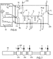
- a read circuit 140 as described above in connection with the figures 3, 4 , 5A-5B , and provided with a stage 141 with transistors M1, M2, M3, respectively of type N, of type N and of type P applies in particular to a photodiode 120 called "P on N", that is to say equipped with a zone P surmounted by a zone N to which the stage 141 of the read circuit is connected, in particular to which the source of the first transistor M1 and the gate of the second transistor M2 are connected.
- the transistor stage 241 the polarization mode of which is able to be modified in order to enable the operating modes DI and BDI to be adapted, is also composed of 3 transistors M'1, M'2, M'3.
- the first transistor M'1 is of type P, for example PMOS.
- the gate of this transistor M'1 is connected to a common electrode between a second P-type transistor M'2, in particular PMOS, and a third N-type transistor M'3, in particular NMOS.
- the transistor T ' 1 of the reset stage of the integration capacitor, T' 2 of the storage stage, T ' 3 of reset of the storage capacitor, as well as the transistors T' 4 , Column and row selection T ′ 5 are of the type opposite to that of the device described above, and in this example of type P (in particular of PMOS type).
- the figure 7 shows, for this variant, the polarization control block 90 at the edge of a row or line and making it possible to adapt the polarization mode DI or BDI connected to the reading circuits or reading pixels 240 respective of the detection elements of this row .
- a same polarization mode is imposed on the read pixels of a same row, this polarization mode possibly being shared by all the rows of the matrix.
- an operating mode in particular DI or BDI
- a first region Z1 of a matrix of detection elements 130 ij is thus subjected to a DI mode, while at another region Z2 of this matrix the BDI mode is imposed.
- adjacent or neighboring elements 130 11 and 130 12 of the first region Z1 can each be put into DI mode, while adjacent or neighboring elements (not referenced in the figure) of the first region Z2 can each be put into BDI mode. .
- the respective read circuits of the detection elements of the first region Z1 are subjected to a set of bias signals VDI1, VBIAS1, VBI1 different from the signals VDI2, VBIAS2, VBI2, bias of the respective read circuits of the detection elements. of the second region Z2.
- the second region Z2 can be a region of the imager corresponding to a region of the scene for which the image quality is favored, the first region Z1 corresponding to an image region of lower quality.
- the two sets of polarization signals VDI1, VBIAS1, VBI1, VDI2, VBIAS2, VBI2 assigned respectively to the first region Z1 and to the second region Z2 come from the same polarization control block 90 external to the matrix M of detection elements.
- a device with several separate control blocks 90a, 90b.
- a first control block 90a can be configured to apply signals of polarization to a region Z1, to make it adopt a particular operating mode selected between several operating modes, in particular between DI or BDI operation, while a second control block 90b is configured to apply polarization signals to a another region Z3, and make it adopt a given operating mode between several operating modes, in particular between BDI or DI operation.
- An external and reconfigurable polarization control block as described in either embodiment can be provided with or associated with a controller making it possible to impose on the switching circuit (s) the configuration (s). respective.
- a particular arrangement illustrated on the figure 9 provide a controller 80 external to the imager or to the chip containing the imager, or else integrated on the chip.
- This controller 80 can be a circuit provided with at least one logic block, or for example in the form of a microprocessor or an ASIC circuit (for “application-specific integrated circuit” or “integrated circuit specific to an application. ”) Required to modify the configuration of the switching circuit (s) by means of Sconfig configuration signals.
- the controller 80 can itself be controlled by a digital control system 70 emitting for example at least one Szone signal for selecting a given imager region, a Smode signal relating to a given operating mode selection, DI or BDI, or a zone / mode signal S associating, with a given imager region, a given operating mode chosen in particular between DI and BDI.
- a digital control system 70 emitting for example at least one Szone signal for selecting a given imager region, a Smode signal relating to a given operating mode selection, DI or BDI, or a zone / mode signal S associating, with a given imager region, a given operating mode chosen in particular between DI and BDI.
- the choice of a given operating mode, DI or BDI, for a given imager region can depend on the level of resolution that one wishes to assign to this given region, this assignment itself being able to depend on a discrimination carried out. between at least one area of interest and at least one other area of lesser interest identified in a scene detected by the imager.
- the control system 70 can be for example in the form of a data processor, integrated or not on the chip, or of a computer intended to receive data making it possible to define one or more zones of interest on an imaged scene in order to to generate a signal making it possible to assign to at least one region of the matrix a mode BDI operating mode and to another region of the matrix a DI operating mode for which the detection precision is lower but where current consumption is reduced.
- One or the other of the embodiments described above apply particularly to cooled infrared imagers and therefore provided with a device for cooling the matrix, in particular a fluidic device in which a cooling fluid is circulated. to keep the imager at a low operating temperature, for example below 150K.
- the device according to the invention applies in particular to cooled infrared imagers fitted with photo-detectors designed to operate at “high” temperatures, for example between 130 K and 150 K but for which the value of the shunt resistance R is low.
- the device according to the invention also advantageously applies to so-called “low flux” applications, of the order of tens of peak amperes or less.
Landscapes
- Physics & Mathematics (AREA)
- General Physics & Mathematics (AREA)
- Spectroscopy & Molecular Physics (AREA)
- Engineering & Computer Science (AREA)
- Multimedia (AREA)
- Signal Processing (AREA)
- Transforming Light Signals Into Electric Signals (AREA)
- Solid State Image Pick-Up Elements (AREA)
- Photometry And Measurement Of Optical Pulse Characteristics (AREA)
Abstract
Bloc (90) de commande de polarisation externe pour un circuit de lecture d'élément photo-détecteur infrarouge, le bloc de commande pouvant adopter :- une première configuration dans laquelle il émet un premier ensemble de signaux de polarisation (VDI1, VBIAS1, VBI1) à un premier étage (141, 241) du circuit de lecture de sorte que ce premier étage (141, 241) adopte un premier mode de fonctionnement correspondant à un premier mode de polarisation du photo-détecteur, en particulier un mode d'injection directe (DI),- une deuxième configuration dans laquelle il émet un deuxième ensemble de signaux de polarisation (VDI2, VBIAS2, VBI2) audit premier étage (141, 241), les signaux du deuxième ensemble étant prévus de sorte que ledit premier étage (141, 241) adopte un deuxième mode de fonctionnement correspondant à un deuxième mode de polarisation du photo-détecteur, en particulier un mode d'injection directe contre-réactionnée (BDI).External polarization control unit (90) for an infrared photo-detector element read circuit, the control unit being able to adopt: - a first configuration in which it emits a first set of polarization signals (VDI1, VBIAS1, VBI1 ) to a first stage (141, 241) of the read circuit so that this first stage (141, 241) adopts a first operating mode corresponding to a first polarization mode of the photo-detector, in particular an injection mode direct (DI), - a second configuration in which it transmits a second set of bias signals (VDI2, VBIAS2, VBI2) to said first stage (141, 241), the signals of the second set being provided so that said first stage ( 141, 241) adopts a second operating mode corresponding to a second polarization mode of the photo-detector, in particular a feedback direct injection (BDI) mode.
Description
La présente invention se rapporte au domaine des dispositifs d'imagerie infrarouge, et en particulier à celui des imageurs infrarouge refroidis et est relative au circuit de lecture des éléments photo-détecteurs, ainsi qu'à leur polarisation.The present invention relates to the field of infrared imaging devices, and in particular to that of cooled infrared imagers, and relates to the circuit for reading the photo-detector elements, as well as to their polarization.
Lorsqu'une scène est observée par un imageur infrarouge formé d'une matrice d'éléments de détection, chaque élément de détection délivre un courant proportionnel à l'éclairement reçu par cet élément.When a scene is observed by an infrared imager formed by a matrix of detection elements, each detection element delivers a current proportional to the illumination received by this element.
Une structure conventionnelle d'un élément de détection infrarouge IR est illustrée sur la
L'état d'une scène observée peut donc être suivi au moyen de la tension aux bornes du condensateur Cint. Le courant émis par la photodiode 2 traverse dans l'exemple illustré une structure dite d'injection directe (DI pour « Direct Injection ») qui sert à polariser la photodiode 2 de manière appropriée et atteint le condensateur Cint. La structure DI peut être sous forme d'un transistor 5, qui permet de maintenir une polarisation fixe sur la photodiode 2 lors de l'intégration de courant par le condensateur de stockage Cint et d'isoler la photodiode 2 des variations de la tension aux bornes du condensateur Cint.The state of an observed scene can therefore be followed by means of the voltage at the terminals of the capacitor Cint. The current emitted by the
L'impédance d'entrée Rin de la structure DI, qui représente sa capacité à maintenir une tension de polarisation fixe malgré des variations de courant de photodiode 2, peut s'exprimer par la formule simplifiée suivante : 
Cette approximation est due au fait que les niveaux de courants de photodiode 2 sont faibles et que le transistor 5 se trouve typiquement polarisé dans un régime de faible inversion. L'impédance d'entrée Rin est donc ici inversement proportionnelle au courant de photodiode 2 et est indépendante de la taille du transistor 5. Cette impédance d'entrée Rin est d'autant plus importante que le pas des pixels dans la matrice est réduit et que les courants générés sont donc plus faibles.This approximation is due to the fact that the current levels of
Un bon indicateur de performance d'un élément de détection est son rendement d'injection qui donne le rapport entre le courant qui rentre qui est donc intégré sur la capacité de stockage Cint et le courant généré par la photodiode 2. Or, une augmentation de l'impédance d'entrée Rin va dans le sens d'une détérioration du rendement d'injection. En statique, cela peut se traduire par des pertes de signal, de sorte que tout le courant généré ne rejoindra pas la capacité d'intégration Cint, ainsi que des non-linéarités, tandis qu'en dynamique, le circuit de lecture a tendance à ne pas réagir aux variations rapides de signal.A good performance indicator of a detection element is its injection efficiency which gives the ratio between the incoming current which is therefore integrated into the storage capacity Cint and the current generated by the
La
Une telle architecture répond au besoin de diminution de l'impédance d'entrée du circuit de lecture puisqu'elle peut permettre une réduction d'un facteur A (A étant le gain de l'amplificateur) par rapport à l'utilisation d'une structure DI. Toutefois la structure BDI peut poser cette fois un problème de consommation inutile dans certains cas.Such an architecture meets the need for reducing the input impedance of the read circuit since it can allow a reduction by a factor A (A being the gain of the amplifier) compared to the use of a DI structure. However, the BDI structure can pose this time a problem of unnecessary consumption in certain cases.
Il est donc difficile de pouvoir concilier les deux critères précédemment évoqués.It is therefore difficult to be able to reconcile the two criteria mentioned above.
Le document
Il se pose le problème de trouver un nouveau dispositif d'imagerie infrarouge amélioré vis-à-vis d'inconvénient(s) mentionné(s) ci-dessus.The problem arises of finding a new infrared imaging device improved with respect to the drawback (s) mentioned above.
Un mode de réalisation de la présente demande prévoit un bloc externe de commande de polarisation pour au moins un circuit de lecture d'au moins un photo-détecteur infrarouge, ce bloc de commande étant reconfigurable entre une première configuration et une deuxième configuration et inversement, la première configuration étant une configuration dans laquelle le bloc de commande de polarisation est configuré pour émettre un premier ensemble de signaux de polarisation à un premier étage à transistors du circuit de lecture de sorte que ce premier étage adopte un premier mode de fonctionnement, correspondant en particulier à un premier mode de polarisation du photo-détecteur, en particulier de type à injection directe
la deuxième configuration étant une configuration dans laquelle ce bloc de commande est configuré pour émettre un deuxième ensemble de signaux de polarisation audit premier étage à transistors du circuit de lecture, les signaux du deuxième ensemble étant prévus de sorte que ledit premier étage adopte un deuxième mode de fonctionnement correspondant à un deuxième mode de polarisation du photo-détecteur, en particulier un mode de polarisation de type à injection directe.An embodiment of the present application provides for an external polarization control unit for at least one reading circuit of at least one infrared photo-detector, this control unit being reconfigurable between a first configuration and a second configuration and vice versa, the first configuration being a configuration in which the bias control block is configured to output a first set of bias signals to a first transistor stage of the read circuit so that this first stage adopts a first mode of operation, corresponding in particular to a first mode of polarization of the photo-detector, in particular of the direct injection type
the second configuration being a configuration in which this control unit is configured to output a second set of bias signals to said first transistor stage of the read circuit, the signals of the second set being provided such that said first stage adopts a second mode operating mode corresponding to a second polarization mode of the photo-detector, in particular a direct injection type polarization mode.
Ainsi, c'est un bloc de commande de polarisation externe aux éléments de détection dont on vient modifier la configuration pour pouvoir passer d'un mode de polarisation à l'autre sans nécessairement devoir ajouter de composant au pixel de lecture.Thus, it is a polarization control unit external to the detection elements whose configuration has just been modified in order to be able to switch from one polarization mode to the other without necessarily having to add a component to the read pixel.
Ainsi, un aspect de la présente invention concerne un dispositif imageur infrarouge comportant une pluralité d'éléments de détection chaque élément de détection comprenant un photo-détecteur associé et connecté à un pixel de lecture d'un signal généré par le photo-détecteur, le pixel de lecture étant doté d'une charge capacitive d'intégration pour stocker des charges provenant du photo-détecteur, le pixel de lecture comprenant un premier étage, couplé au photo-détecteur et à la charge capacitive d'intégration, ledit premier étage étant doté de transistors et servant à la polarisation du photo-détecteur,
le dispositif imageur étant doté d'au moins un bloc de commande de polarisation externe à ladite pluralité d'éléments de détection, ledit bloc de commande de polarisation externe étant apte à appliquer audit premier étage du pixel de lecture un ensemble de potentiels de polarisation, le bloc de commande de polarisation externe étant reconfigurable de sorte à être apte à passer d'une première configuration à une deuxième configuration et de la deuxième configuration à la première configuration, la première configuration étant une configuration dans laquelle le bloc de commande de polarisation est configuré pour émettre un premier ensemble de signaux de polarisation audit premier étage de sorte que ledit premier étage adopte un premier mode de fonctionnement correspondant à un premier mode de polarisation du photo-détecteur.Thus, one aspect of the present invention relates to an infrared imaging device comprising a plurality of detection elements, each detection element comprising a photo-detector associated and connected to a reading pixel of a signal generated by the photo-detector, the read pixel being provided with an integrating capacitive load for storing charges from the photo-detector, the read pixel comprising a first stage, coupled to the photo-detector and to the integrating capacitive load, said first stage being equipped with transistors and used for the polarization of the photo-detector,
the imaging device being provided with at least one polarization control block external to said plurality of detection elements, said external polarization control unit being able to apply to said first stage of the read pixel a set of polarization potentials, the external polarization control unit being reconfigurable so as to be able to pass from a first configuration to a second configuration and from the second configuration to the first configuration, the first configuration being a configuration in which the polarization control unit is configured to transmit a first set of polarization signals to said first stage such that said first stage adopts a first mode of operation corresponding to a first mode of polarization of the photo-detector.
La deuxième configuration étant une configuration dans laquelle le bloc de commande est configuré pour émettre un deuxième ensemble de signaux de polarisation audit premier étage, les signaux du deuxième ensemble étant différents des signaux du premier ensemble et prévus de sorte que ledit premier étage à transistors adopte un deuxième mode de fonctionnement correspondant à un deuxième mode de polarisation du photo-détecteur.The second configuration being a configuration in which the control unit is configured to output a second set of bias signals to said first stage, the signals of the second set being different from the signals of the first set and provided so that said first transistor stage adopts a second operating mode corresponding to a second polarization mode of the photo-detector.
Le premier mode de polarisation du photodétecteur est typiquement un mode de polarisation à injection directe (DI), tandis que ledit deuxième mode de polarisation de la photodiode est typiquement un mode de polarisation à injection directe contre-réactionnée (BDI) du photodétecteur.The first photodetector bias mode is typically a direct injection (DI) bias mode, while said second photodiode bias mode is typically a feedback direct injection (BDI) bias mode of the photodetector.
Dans le mode d'injection directe un ensemble de transistors du premier étage sont polarisés de sorte que ledit pixel de lecture a une première impédance d'entrée, tandis que dans le mode d'injection directe contre réactionnée, ledit ensemble de transistors dudit premier étage sont polarisés de sorte que ledit pixel de lecture a une deuxième impédance d'entrée inférieure à la première impédance.In the direct injection mode a set of transistors of the first stage are biased so that said read pixel has a first input impedance, while in the direct reverse injection mode, said set of transistors of said first stage are biased such that said read pixel has a second input impedance lower than the first impedance.
Un bloc de commande de polarisation externe permet de configurer individuellement en mode DI ou BDI les éléments de détection. Avec un bloc de commande externe, la configuration d'un élément de détection DI ou BDI d'un élément de détection n'est pas nécessairement liée à celle d'un élément de détection voisin. Avec le bloc de commande de polarisation externe il est possible de configurer en un même mode DI ou BDI deux éléments de détection adjacents ou voisins d'une même rangée (ligne ou colonne) d'élément de détection.An external polarization control block allows the detection elements to be individually configured in DI or BDI mode. With an external control block, the configuration of a DI or BDI sensing element of a sensing element is not necessarily linked to that of a neighboring sensing element. With the external polarization control unit, it is possible to configure in the same DI or BDI mode two adjacent or neighboring detection elements of the same row (row or column) of detection element.
Avantageusement, le premier étage peut être formé d'un premier transistor dit d'injection directe connecté au photo-détecteur et à la charge capacitive d'intégration, d'un deuxième transistor, et d'un troisième transistor, le deuxième transistor et le troisième transistor étant connectés au bloc de commande de polarisation externe.Advantageously, the first stage can be formed of a first so-called direct injection transistor connected to the photo-detector and to the integration capacitive load, of a second transistor, and of a third transistor, the second transistor and the third transistor being connected to the external bias control block.
Un étage avec seulement trois transistors peut être prévu pour gérer la polarisation du photo-détecteur et passer d'un mode DI à un mode BDI et inversement.A stage with only three transistors can be provided to manage the polarization of the photo-detector and to switch from a DI mode to a BDI mode and vice versa.
Dans le premier mode de fonctionnement, les signaux du premier ensemble de signaux de polarisation peuvent être prévus de sorte à faire fonctionner le troisième transistor comme un interrupteur fermé tout faisant fonctionner le deuxième transistor comme un interrupteur ouvert ou tout en rendant inopérant le deuxième transistor en l'isolant du reste du premier étage.In the first mode of operation, the signals of the first set of bias signals may be provided so as to operate the third transistor as a closed switch while operating the second transistor as an open switch or while rendering the second transistor inoperative. isolating it from the rest of the first floor.
Avantageusement, dans le premier mode de fonctionnement, une électrode du deuxième transistor peut être laissée flottante. On s'assure de cette manière qu'aucun courant ne passe à travers le deuxième transistor.Advantageously, in the first mode of operation, an electrode of the second transistor can be left floating. In this way, it is ensured that no current passes through the second transistor.
Dans le deuxième mode de fonctionnement, le deuxième transistor et le troisième transistor peuvent réaliser un amplificateur de courant.In the second mode of operation, the second transistor and the third transistor can realize a current amplifier.
Avantageusement, dans la deuxième configuration, le bloc de commande applique un potentiel négatif à une électrode du deuxième transistor. En utilisant une telle polarisation négative plutôt que par exemple une mise à la masse, un gain en dynamique de tension aux bornes de la charge capacitive peut être obtenu, ce qui peut permettre d'améliorer le rapport signal sur bruit.Advantageously, in the second configuration, the control unit applies a negative potential to an electrode of the second transistor. By using such a negative bias rather than for example a grounding, a gain in dynamics voltage across the capacitive load can be obtained, which can improve the signal-to-noise ratio.
Selon un mode de réalisation le bloc de commande de polarisation comporte une portion de circuit apte à former un miroir de courant. Dans ce cas, dans la deuxième configuration, le troisième transistor forme avec ladite portion de circuit ce miroir de courant, de sorte à copier un courant généré par ladite portion de circuit du bloc de commande.According to one embodiment, the polarization control unit comprises a portion of the circuit capable of forming a current mirror. In this case, in the second configuration, the third transistor forms with said circuit portion this current mirror, so as to copy a current generated by said circuit portion of the control unit.
Le bloc de commande de polarisation externe peut être doté d'une pluralité de sorties vers lesquelles les signaux de polarisation formant un ensemble de signaux de polarisation sont respectivement émis, et d'au moins un circuit de commutation comportant une pluralité d'interrupteurs, le circuit de commutation permettant de connecter sélectivement chaque sortie à une ou plusieurs voies d'une pluralité de voies auxquelles des potentiels de polarisation sont appliqués, un ou plusieurs interrupteurs donnés de ladite pluralité d'interrupteur ayant des états respectifs, ouvert ou fermé, différents entre ladite première configuration et ladite deuxième configuration.The external bias control block may be provided with a plurality of outputs to which the bias signals forming a set of bias signals are respectively output, and at least one switching circuit comprising a plurality of switches, the switching circuit making it possible to selectively connect each output to one or more channels of a plurality of channels to which bias potentials are applied, one or more given switches of said plurality of switches having respective states, open or closed, different between said first configuration and said second configuration.
Un mode de réalisation particulier prévoit d'affecter à un ou plusieurs éléments de détection d'un imageur un mode de polarisation de type DI et concomitamment à un ou plusieurs autres éléments de détection de l'imageur un mode de polarisation de type BDIA particular embodiment provides for assigning to one or more detection elements of an imager a mode of polarization of the DI type and concomitantly to one or more other detection elements of the imager a mode of polarization of the BDI type.
Ainsi, selon une possibilité de mise en œuvre pour laquelle une pluralité d'éléments de détection est située dans une première région d'une matrice d'éléments de détection, un premier ensemble de signaux de polarisation est émis par ledit bloc de commande de polarisation à cette pluralité d'éléments de détection, tandis qu'à une deuxième pluralité d'éléments de détection de l'imageur situés dans une deuxième région de la matrice d'éléments de détection on applique concomitamment un deuxième ensemble de signaux de polarisation distinct des signaux du premier ensemble.Thus, according to an implementation possibility for which a plurality of detection elements is located in a first region of an array of detection elements, a first set of bias signals is emitted by said bias control block to this plurality of detection elements, while to a second plurality of detection elements of the imager situated in a second region of the array of detection elements, a second set of polarization signals distinct from the signals from the first set.
Selon une possibilité de mis en œuvre du dispositif comprenant un autre bloc de commande de polarisation externe, ledit autre bloc de commande de polarisation externe étant couplé à ladite deuxième pluralité d'éléments de détection et apte à appliquer aux pixels de lecture respectifs dudit deuxième ensemble d'éléments de détection, ledit deuxième ensemble de signaux de polarisation.According to one possible implementation of the device comprising another external polarization control unit, said other external polarization control unit being coupled to said second plurality of detection elements and capable of applying to respective read pixels of said second set of sensing elements, said second set of bias signals.
Selon un aspect particulier, l'invention concerne un imageur infrarouge refroidi comprenant un dispositif imageur tel que défini plus haut.According to a particular aspect, the invention relates to a cooled infrared imager comprising an imaging device as defined above.
La présente invention sera mieux comprise sur la base de la description qui va suivre et des dessins en annexe sur lesquels :
- La
figure 1 sert à illustrer, dans un imageur infrarouge, un exemple de pixel de lecture de type DI (« Direct Injection ») ; - La
figure 2 sert à illustrer, dans un imageur infrarouge, un exemple de pixel de lecture de type BDI (« Buffered Direct Injection ») ; - La
figure 3 sert à illustrer un exemple de dispositif imageur infrarouge associant à un pixel de lecture d'un élément de photo-détection, un bloc de commande de polarisation externe reconfigurable étant amené à faire passer ce pixel de lecture d'un mode de fonctionnement de type DI à un mode de fonctionnement de type BDI et inversement ; - La
figure 4 sert à illustrer un agencement particulier du bloc de commande de polarisation externe situé à une extrémité d'une rangée d'éléments de détection ; - La
figure 5A sert à illustrer une première configuration d'un circuit de commutation du bloc de commande de polarisation pour faire adopter au circuit de lecture un mode de fonctionnement de type DI ; - La
figure 5B sert à illustrer une deuxième configuration d'un circuit de commutation du bloc de commande de polarisation pour faire adopter au circuit de lecture un mode de fonctionnement de type BDI ; - Les
figures 6 et 7 servent à illustrer une variante d'agencement du circuit de lecture adaptée à une connexion de ce dernier sur une zone P d'une photodiode de type P sur N ; - La
figure 8A sert à illustrer un mode de réalisation particulier dans lequel un imageur est doté d'éléments de détection fonctionnant en mode DI et d'autres d'éléments de détection fonctionnant de manière concomitante en mode BDI ; - La
figure 8B sert à illustrer un imageur doté d'une région fonctionnant en mode DI et d'une autre région fonctionnant de manière concomitante en mode BDI, ces régions ayant leurs modes de fonctionnement respectifs DI ou BDI imposés par des blocs de commande de polarisation distincts ; - La
figure 9 sert à illustrer un système numérique dans lequel le bloc de commande de polarisation et en particulier la configuration de son circuit de commutation est-elle-même commandée par un contrôleur;
- The
figure 1 serves to illustrate, in an infrared imager, an example of a DI (“Direct Injection”) type reading pixel; - The
figure 2 serves to illustrate, in an infrared imager, an example of a reading pixel of BDI (“Buffered Direct Injection”) type; - The
figure 3 is used to illustrate an example of an infrared imaging device associating with a read pixel of a photo-detection element, a reconfigurable external polarization control unit being caused to change this read pixel from an operating mode of DI type to a BDI type operating mode and vice versa; - The
figure 4 serves to illustrate a particular arrangement of the external bias control block located at one end of a row of sensing elements; - The
figure 5A serves to illustrate a first configuration of a switching circuit of the bias control unit to make the read circuit adopt an operating mode of the DI type; - The
figure 5B serves to illustrate a second configuration of a switching circuit of the bias control unit to make the read circuit adopt a BDI type operating mode; - The
figures 6 and 7 serve to illustrate an alternative arrangement of the read circuit suitable for connection of the latter to a P area of a P on N type photodiode; - The
figure 8A serves to illustrate a particular embodiment in which an imager is provided with sensing elements operating in DI mode and other sensing elements operating concomitantly in BDI mode; - The
figure 8B serves to illustrate an imager having one region operating in DI mode and another region operating concomitantly in BDI mode, these regions having their respective DI or BDI operating modes imposed by separate polarization control blocks; - The
figure 9 serves to illustrate a digital system in which the bias control unit and in particular the configuration of its switching circuit is itself controlled by a controller;
Des parties identiques, similaires ou équivalentes des différentes figures portent les mêmes références numériques de façon à faciliter le passage d'une figure à l'autre.Identical, similar or equivalent parts of the different figures bear the same numerical references so as to facilitate the passage from one figure to another.
Les différentes parties représentées sur les figures ne le sont pas nécessairement selon une échelle uniforme, pour rendre les figures plus lisibles.The different parts shown in the figures are not necessarily on a uniform scale, to make the figures more readable.
Un exemple de structure d'un circuit de lecture 140 d'imageur infrarouge tel que mis en œuvre suivant un mode de réalisation de la présente invention est donné sur la
Le circuit de lecture 140, également appelé « pixel de lecture », est connecté à un photo-détecteur tel qu'une photodiode 120 qui transforme un rayonnement infrarouge en un courant électrique. La photodiode 120 et le circuit de lecture 140 associé forment un élément de détection 130. L'imageur compte généralement une pluralité d'éléments de détection 130 qui peuvent être agencés en matrice, d'une ou plusieurs rangées d'éléments de détection.The
La photodiode 120 est typiquement polarisée en inverse et délivre au circuit de lecture 140 un courant représentatif d'une scène observée. La photodiode 120 peut être en particulier réalisée dans un substrat en matériau de type III-V, par exemple, InP, GaAS, InGaAs, InSb ou de type II-VI par exemple HgCdTe et peut être rapportée sur le circuit de lecture 140 selon un assemblage que l'on nomme couramment « hybridation ». Le circuit de lecture 140 et la photodiode 120 sont alors reliés mécaniquement et électriquement par exemple par le biais de billes métalliques.The
Pour polariser la photodiode 120, on applique à une de ses bornes un potentiel Vpold, tandis que l'autre borne Sphotodiode est couplée à un étage 141 du circuit de lecture 140, sous forme d'un circuit à transistor(s). Dans cet exemple, l'étage 141 est formé seulement de 3 transistors M1, M2, M3. Le potentiel Vpold est avantageusement un potentiel qui demeure fixe d'une lecture à l'autre du courant de la photodiode.To bias the
Les transistors M1, M2, M3, en fonction de la manière dont ils sont eux-mêmes polarisés et le régime de fonctionnement qu'ils adoptent en conséquence permettent d'ajuster la polarisation à une borne Sphotodiode de la photodiode 120 ainsi que l'impédance d'entrée Rin du circuit de lecture 140. La polarisation des transistors M1, M2, M3 qui détermine la polarisation de la photodiode 120 ainsi que l'impédance d'entrée Rin du circuit de lecture 140, est ici destiné à être modulé. Une particularité de ce dispositif, réside en effet en ce que la polarisation des transistors M1, M2, M3, est amenée à être modifiée après conception de l'imageur et lorsque ce dernier se trouve en fonctionnement en modifiant les potentiels de polarisations appliqués à des bornes B1, B2, B3, du circuit de lecture 140. De cette manière, l'étage 141, est susceptible d'adopter des modes de fonctionnements différents correspondants à des modes de polarisations différents appliqués à la photodiode.The transistors M1, M2, M3, depending on the way in which they are themselves polarized and the operating regime they adopt as a result, allow the polarization at a Sphotodiode terminal of the
Dans cet exemple de réalisation l'étage 141 compte un premier transistor M1 relié à la photodiode 120 et appelé transistor d'injection directe. Ce premier transistor M1 permet de lire le signal délivré par la photodiode 120 et de maintenir une polarisation adéquate sur la photodiode 120 lors d'une intégration de courant provenant de la photodiode 120. Le premier transistor M1 est dans cet exemple de réalisation un transistor de type N, en particulier un transistor NMOS, dont une électrode, en particulier le drain, est reliée à une charge capacitive d'intégration 143, et dont une autre électrode, en particulier la source, est reliée à la photodiode 120. La charge capacitive 143 est par exemple formée d'un condensateur Cint.In this exemplary embodiment,
L'étage 141 est ici également formé d'un deuxième transistor M2, et d'un troisième transistor M3 qui, dans cet exemple de réalisation, respectivement de type N, en particulier un NMOS et de type P, en particulier un PMOS. Les transistors M2 et M3 ont une électrode commune, dans cet exemple une électrode de drain, qui est reliée à la grille du transistor d'injection directe M1. Dans l'exemple de réalisation illustré sur la
Les transistors M2 et M3 sont reliés aux bornes B1, B2, B3 auxquelles des signaux de polarisation destinés à l'étage 141 sont destinés à être appliqués et qui proviennent de sorties S1, S2, S3 d'un bloc 90 de commande de signaux de polarisation.Transistors M2 and M3 are connected to terminals B1, B2, B3 to which bias signals intended for
Ce bloc 90 de commande de polarisation est externe au circuit de lecture 140 et à l'élément de détection 130. Le bloc 90 de commande peut être un circuit situé en bord de la matrice d'éléments de détection 130 et donc situé à l'extérieur de cette matrice.This
Le bloc 90 de commande peut être configuré pour appliquer des signaux de polarisation aux circuits de lecture 140 respectifs et en particulier aux étages 141 à transistors respectifs de plusieurs éléments de détection 130.The
Dans l'exemple de réalisation particulier illustré sur la
Comme indiqué plus haut, une particularité du dispositif réside en ce que l'étage 141 du circuit de lecture 140 peut adopter plusieurs modes de fonctionnement et en particulier alterner entre deux modes de fonctionnement.As indicated above, a feature of the device resides in that the
Dans l'exemple de réalisation illustré, le circuit de lecture 140 peut passer d'un mode de polarisation de type à injection directe ou DI (pour « Direct Injection ») à un mode de polarisation de type à injection directe contre-réactionnée ou BDI (pour « Buffered Direct Injection ») et inversement. Le passage d'un mode de fonctionnement à l'autre, autrement dit à un mode de polarisation à l'autre de la photodiode 120 (DI vers BDI ou BDI vers DI), est ici réalisé sans nécessairement devoir ajouter de composant(s) et en particulier de transistor supplémentaire, en modifiant la manière dont l'étage 141, ici formé de 3 transistors est polarisé.In the exemplary embodiment illustrated, the
Le passage d'un mode de fonctionnement à l'autre est mis en œuvre au moyen des signaux de polarisation aux bornes B1, B2, B3 émis par le bloc de commande 90. Le bloc de commande 90 est en particulier prévu pour transmettre une première série de signaux de polarisation aux bornes B1, B2, B3 de l'étage 41 afin de placer le circuit de lecture dans un mode de polarisation DI et pour transmettre aux bornes B1, B2, B3 une deuxième série de signaux de polarisation, différente de la première série à l'étage 41 afin de placer le circuit de lecture 140 dans un mode de polarisation BDI.The change from one operating mode to another is implemented by means of the polarization signals at the terminals B1, B2, B3 transmitted by the
On assure ici une re-configurabilité du pixel de lecture 140 sans ajouter de transistor supplémentaire dans ce pixel. On déporte la gestion de la commutation d'un mode de fonctionnement à l'autre en périphérie de la matrice de pixels, par exemple en bout de ligne ou en bout de colonne.Here, re-configurability of the
Pour assurer cette re-configurabilité un mode de réalisation on peut typiquement prévoir de doter le bloc de commande 90 d'au moins un circuit de commutation 100. Le circuit de commutation 100 est dans cet exemple pourvu d'interrupteurs 101, 102, 103, 104, 105 qui permettent, en fonction de leurs états respectifs, fermé ou ouvert (ON ou OFF) d'alternativement connecter une sortie S1, S2, S3 à une voie de polarisation ou déconnecter une sortie S1, S2, S3 d'une voie de polarisation.To ensure this reconfigurability, one embodiment can typically be provided to provide the
Lorsqu'un premier interrupteur 101 est dans un état fermé (et qu'un deuxième interrupteur 102 est ouvert), cet interrupteur 101 permet par exemple de relier la sortie S12 à une voie de polarisation sur laquelle un premier potentiel d'alimentation VGDI est appliqué.When a
Lorsque le deuxième interrupteur 102 est ouvert (et que le premier interrupteur 101 est fermé) cela permet par exemple de relier la sortie S1 à une voie de polarisation sur laquelle un potentiel VDDmiroir est émis. Ce potentiel VDDmiroir est par exemple délivré par une portion de circuit 108 du bloc de commande 90 apte à former un miroir de courant.When the
Lorsqu'un troisième interrupteur 103 est fermé (et qu'un quatrième interrupteur 104 est ouvert) cela permet par exemple de relier la sortie S2 à une voie de polarisation correspondant à un potentiel de grille d'un transistor T de la portion 108 de circuit.When a
A l'état fermé (et lorsque le troisième interrupteur 103 est ouvert) le quatrième interrupteur 104 permet par exemple de relier la sortie S2 à la masse.In the closed state (and when the
A l'état fermé, un cinquième interrupteur 105 permet par exemple de relier la sortie S3 à une voie de polarisation sur laquelle un potentiel d'alimentation VBDI est appliqué.In the closed state, a
A l'état ouvert, le cinquième interrupteur 105 permet de laisser la sortie S3 flottante et la borne B3 connectée à cette sortie S3 également flottante.In the open state, the
Le bloc 90 de commande de polarisation externe et en particulier son circuit de commutation 100 est ainsi reconfigurable en fonction de signaux (non représentés) de commande d'ouverture ou de fermeture des interrupteurs 101, 102, 103, 104, 105.The external
Les
Une première configuration (
Les potentiels VDI1=VGDI, Vbias12=VGND appliqués respectivement à la source et à la grille du troisième transistor M3, sont prévus de sorte que ce transistor M3 fonctionne en interrupteur, le transistor M3 étant rendu passant de sorte à acheminer la tension VGDI jusqu'à la grille du premier transistor M1 d'injection directe. VGDI est dans cet exemple un potentiel positif qui peut être par exemple de l'ordre de 1V L'état ouvert du cinquième interrupteur 105 dans le circuit de commutation 100 rend la borne B3 flottante ce qui permet de s'assurer que le deuxième transistor M2 fonctionne comme un interrupteur ouvert et ainsi laissé inopérant dans l'étage 141.The potentials VDI1 = VGDI, Vbias12 = VGND applied respectively to the source and to the gate of the third transistor M3, are provided so that this transistor M3 operates as a switch, the transistor M3 being turned on so as to carry the voltage V GDI up to 'to the gate of the first direct injection transistor M1. VGDI is in this example a positive potential which can be for example of the order of 1V The open state of the
En rendant la borne B3 flottante, on permet ainsi de s'assurer qu'aucun courant supplémentaire ne circule à travers ce transistor M2 et que la grille du transistor d'injection directe est uniquement polarisée par l'intermédiaire du potentiel VDI. Dans ce mode de fonctionnement DI, le transistor d'injection M1 qui est monté en cascode, reçoit un potentiel fixe sur sa grille. La polarisation des transistors M1, M2, M3 est alors telle que la résistance d'entrée du circuit de lecture 140 a une première valeur.By making the terminal B3 floating, it is thus possible to ensure that no additional current flows through this transistor M2 and that the gate of the direct injection transistor is only biased via the potential V DI . In this operating mode DI, the injection transistor M1 which is mounted as a cascode, receives a fixed potential on its gate. The polarization of the transistors M1, M2, M3 is then such that the input resistance of the read
Une deuxième configuration (
Les potentiels VD12=VDDmiroir, Vbias2, VBDI2=VBDI sont prévus de sorte que les transistors M2, M3 forment un amplificateur de courant. Le troisième transistor M3 est ici polarisé de manière à former une source de courant. Cette source de courant provient du fait que, dans cet exemple de réalisation, la deuxième configuration est telle que la portion 108 du bloc de commande et le troisième transistor M3 forment un montage en miroir de courant. Le potentiel Vbias2 dans cet exemple appliqué à la grille du troisième transistor M3 reliée à la portion de circuit 108 permet de fixer le courant de l'amplificateur réalisé par les transistors M2, M3.The potentials VD12 = VDDmiroir, Vbias2, VBDI2 = VBDI are provided so that the transistors M2, M3 form a current amplifier. The third transistor M3 is here biased so as to form a current source. This current source arises from the fact that, in this exemplary embodiment, the second configuration is such that the
Dans cette deuxième configuration, un potentiel VBDI2=VBDI est appliqué à la source du deuxième transistor M2. Ce potentiel VBDI peut dans cet exemple, être prévu égal au potentiel de masse GND ou de préférence être un potentiel négatif.In this second configuration, a potential VBDI2 = VBDI is applied to the source of the second transistor M2. This potential VBDI can in this example, be provided equal to the ground potential GND or preferably be a negative potential.
En mode BDI, plutôt que de mettre la borne B3 à la masse, en venant adresser une tension négative sur la source du deuxième transistor M2 on améliore la dynamique de tension de la charge capacitive 143. Ce gain de dynamique de tension est particulièrement significatif lorsque l'imageur est de type refroidi et permet une amélioration du rapport signal sur bruit.In BDI mode, rather than putting the terminal B3 to the ground, by coming to address a negative voltage on the source of the second transistor M2, the voltage dynamic of the
Dans le mode de fonctionnement BDI, du fait que le transistor M2 est cette fois rendu opérant, une contre réaction est appliquée sur la grille du premier transistor M1 et une polarisation contre-réactionnée d'une borne de la diode est mise en œuvre. La polarisation des transistors M1, M2, M3 est telle que la résistance d'entrée a dans ce mode BDI une deuxième valeur plus faible que la première valeur de résistance d'entrée dans le mode DI mais également une consommation en courant correspondante plus élevée que dans la première configuration.In the BDI operating mode, because the transistor M2 is this time made operational, a feedback is applied to the gate of the first transistor M1 and a feedback bias of a terminal of the diode is implemented. The polarization of the transistors M1, M2, M3 is such that the input resistance in this BDI mode has a second value lower than the first input resistance value in the DI mode but also a corresponding current consumption higher than in the first configuration.
Dans un circuit de lecture 140 tel que celui illustré sur la
Ainsi, l'étage 143 formant une charge capacitive et permettant d'intégrer le courant issu de la photo-diode 120 est dans l'exemple illustré couplé à un étage 144 de remise à zéro de la charge capacitive 143. Cet étage 144 est commandé par un signal Cresetlnt est peut comprendre un transistor T1 que l'on rend dans cet exemple passant lorsque l'on souhaite vider les charges stockées par la capacité Cint.Thus, the
Un étage 145 de mémorisation est couplé à la charge capacitive 143 et sert à dupliquer une valeur de tension aux bornes de la capacité d'intégration une fois la période d'intégration écoulée.A storage stage 145 is coupled to the
Dans cet exemple, l'étage 145 de mémorisation est doté d'un transistor T2, fonctionnant en interrupteur commandé par un signal CMem, agencé entre le condensateur d'intégration et une capacité C2 de mémorisation. Pour permettre de vider les charges stockées par la capacité de mémorisation et remettre à zéro la valeur de tension mémorisée aux bornes de cette capacité C2, un autre étage 147 de remise à zéro peut être prévu. Cet autre étage 147 est dans cet exemple formé d'un transistor T3 interrupteur que l'on rend passant par le biais d'un signal CresetMem pour décharger la capacité C2, une fois la valeur de tension mémorisée transférée.In this example, the storage stage 145 is provided with a transistor T 2 , operating as a switch controlled by a signal C Mem , arranged between the integration capacitor and a storage capacitor C 2. To make it possible to empty the charges stored by the storage capacitor and reset the voltage value stored at the terminals of this capacitor C 2 to zero, another
Le circuit de lecture 140 est également muni d'un transistor T4 suiveur et d'un transistor T5 de sélection de ligne. Les transistors T4 et T5 sont dans cet exemple également de type N, en particulier NMOSThe
Le circuit de lecture 140 de cet exemple de réalisation particulier a une structure de type IWR (pour « Integrate While Read » ou Intégration pendant lecture), qui du fait de la présence de l'étage de mémorisation, lui permet d'effectuer une intégration pendant qu'une lecture d'une valeur de signal résultant d'une précédente intégration est effectuée.The
On peut toutefois prévoir d'associer l'étage 141 à transistors M1, M2, M3 permettant de faire varier l'impédance d'entrée Rin, à un autre type de structure en aval de la charge capacitive 143 ou à une charge capacitive de structure différente de celle de l'exemple illustré.However, provision can be made to associate the
Un circuit de lecture 140 tel que décrit précédemment en lien avec les
Une variante d'agencement de circuit de lecture 240 adaptée cette fois à une photodiode 220 dite « N sur P », autrement dit dotée d'une zone N surmontée d'une zone P à laquelle le circuit de lecture est connectée, est donnée sur les
Le transistor T'1 de l'étage de remise à zéro du condensateur d'intégration, T'2 de l'étage de mémorisation, T'3 de remise à zéro de la capacité de mémorisation, ainsi que les transistors T'4, T'5 de sélection de colonne et de ligne sont de type opposé à celui du dispositif précédemment décrit, et dans cet exemple de type P (en particulier de type PMOS).The transistor T ' 1 of the reset stage of the integration capacitor, T' 2 of the storage stage, T ' 3 of reset of the storage capacitor, as well as the transistors T' 4 , Column and row selection T ′ 5 are of the type opposite to that of the device described above, and in this example of type P (in particular of PMOS type).
La
En variante, on peut prévoir d'imposer un mode de fonctionnement, en particulier DI ou BDI à une région d'un imageur tandis qu'au même moment, une autre région de cet imageur est soumise à un autre mode de fonctionnement différent, BDI ou DI.As a variant, provision can be made to impose an operating mode, in particular DI or BDI, on a region of an imager while at the same time, another region of this imager is subjected to another different operating mode, BDI or DI.
Dans l'exemple de réalisation particulier illustré sur la
Ainsi, les circuits de lecture respectifs des éléments de détection de la première région Z1 sont soumis à un ensemble de signaux de polarisation VDI1, VBIAS1, VBI1 différents des signaux VDI2, VBIAS2, VBI2, de polarisation des circuits de lecture respectifs des éléments de détection de la deuxième région Z2.Thus, the respective read circuits of the detection elements of the first region Z1 are subjected to a set of bias signals VDI1, VBIAS1, VBI1 different from the signals VDI2, VBIAS2, VBI2, bias of the respective read circuits of the detection elements. of the second region Z2.
La deuxième région Z2 peut être une région de l'imageur correspondant à une région de la scène pour laquelle on privilégie la qualité d'image, la première région Z1 correspondant à une région d'image de moindre qualité. Dans l'exemple illustré sur la
On peut également prévoir comme sur la variante illustrée sur la
Un bloc de commande de polarisation externe et reconfigurable tel que décrit dans l'un ou l'autre des modes de réalisation peut être doté ou associé à un contrôleur permettant d'imposer au(x) circuit(s) de commutation la ou leurs configurations respectives.An external and reconfigurable polarization control block as described in either embodiment can be provided with or associated with a controller making it possible to impose on the switching circuit (s) the configuration (s). respective.
Un agencement particulier illustré sur la
Le contrôleur 80 peut être lui-même commandé par un système de commande numérique 70 émettant par exemple au moins un signal Szone de sélection de région donnée d'imageur, un signal Smode relatif à une sélection de mode de fonctionnement donné, DI ou BDI, ou un signal Szone/mode associant à une région donnée d'imageur, un mode de fonctionnement donné choisi en particulier entre DI et BDI.The
Le choix d'un mode de fonctionnement donné, DI ou BDI, à une région donnée d'imageur peut dépendre du niveau de résolution que l'on souhaite affecter à cette région donnée, cette affectation pouvant elle-même dépendre d'une discrimination effectuée entre au moins une zone d'intérêt et au moins une autre zone de moindre intérêt identifié dans une scène détectée par l'imageur.The choice of a given operating mode, DI or BDI, for a given imager region can depend on the level of resolution that one wishes to assign to this given region, this assignment itself being able to depend on a discrimination carried out. between at least one area of interest and at least one other area of lesser interest identified in a scene detected by the imager.
Le système de commande 70 peut être par exemple sous forme d'un processeur de données, intégré ou non sur la puce, ou d'un ordinateur destiné à recevoir des données permettant de définir une ou des zones d'intérêt sur une scène imagée afin de générer un signal permettant d'affecter à au moins une région de la matrice un mode de fonctionnement BDI et à une autre région de la matrice un mode de fonctionnement DI pour laquelle la précision de détection est plus basse mais où l'on réduit la consommation en courant.The
L'un ou l'autre des exemples de réalisation décrits plus haut s'appliquent particulièrement aux imageurs infrarouge refroidis et donc dotés d'un dispositif de refroidissement de la matrice, en particulier un dispositif fluidique où l'on fait circuler un fluide de refroidissement pour maintenir l'imageur à une température de fonctionnement basse, par exemple inférieure à 150K.One or the other of the embodiments described above apply particularly to cooled infrared imagers and therefore provided with a device for cooling the matrix, in particular a fluidic device in which a cooling fluid is circulated. to keep the imager at a low operating temperature, for example below 150K.
Le dispositif suivant l'invention s'applique en particulier à des imageurs infrarouge refroidis munis de photo-détecteurs conçus pour fonctionner à des températures « élevées », par exemple entre 130 K et 150 K mais pour lesquels la valeur de la résistance Rshunt est faible. Le dispositif suivant l'invention s'applique également avantageusement à des applications dites « faible flux », de l'ordre de dizaines de pico ampères ou inférieurs.The device according to the invention applies in particular to cooled infrared imagers fitted with photo-detectors designed to operate at “high” temperatures, for example between 130 K and 150 K but for which the value of the shunt resistance R is low. The device according to the invention also advantageously applies to so-called “low flux” applications, of the order of tens of peak amperes or less.
Claims (11)
le dispositif imageur étant doté d'au moins un bloc (90) de commande de polarisation ledit bloc (90) de commande de polarisation étant apte à appliquer audit premier étage (141, 241) du pixel de lecture (40, 240) un ensemble de potentiels de polarisation, le bloc (90) de commande de polarisation étant reconfigurable de sorte à être apte à passer d'une première configuration à une deuxième configuration et de la deuxième configuration à la première configuration,
la première configuration étant une configuration dans laquelle le bloc (90) de commande de polarisation est configuré pour émettre un premier ensemble de signaux de polarisation (VDI1, VBIAS1, VBI1) audit premier étage (141, 241) de sorte que ledit premier étage (141, 241) adopte un premier mode de fonctionnement correspondant à un premier mode de polarisation du photo-détecteur (120, 220),
la deuxième configuration étant une configuration dans laquelle le bloc de commande est configuré pour émettre un deuxième ensemble de signaux de polarisation (VDI2, VBIAS2, VBI2) audit premier étage (141, 241), les signaux du deuxième ensemble étant différents des signaux du premier ensemble et prévus de sorte que ledit premier étage (141, 241) à transistors adopte un deuxième mode de fonctionnement correspondant à un deuxième mode de polarisation du photo-détecteur (120, 220), ledit premier mode de polarisation du photo-détecteur (120, 220) étant un mode de polarisation à injection directe (DI) pour lequel un ensemble de transistors (M2, M'2, M3, M'3) du premier étage (141, 241) sont polarisés de sorte que ledit pixel de lecture (140) a une première impédance d'entrée, ledit deuxième mode de polarisation de la photodiode étant un mode de polarisation à injection directe contre-réactionnée (BDI) du photodétecteur pour lequel ledit ensemble de transistors (M2, M'2, M3, M'3) dudit premier étage (141, 241) sont polarisés de sorte que ledit pixel de lecture (140, 240) a une deuxième impédance d'entrée inférieure à la première impédance,
dans lequel chaque élément de détection dudit ensemble d'éléments de détection comprend un pixel de lecture (140, 240),
ledit bloc (90) de commande de polarisation étant externe audit ensemble d'éléments de détection (130).Infrared imaging device comprising a set of detection elements (130) each detection element of said set of detection elements (130) comprising a photo-detector (120, 220) associated and connected to a read pixel (140, 240 ) of a signal generated by the photo-detector (120, 220), the read pixel (140, 240) being provided with an integrating capacitive charge (143) for storing charges from the photo-detector (120 , 220), the read pixel (140, 240) comprising a first stage (141, 241), coupled to the photo-detector (120, 220) and to the integrating capacitive load (143), said first stage being provided transistors (M1, M'1, M2, M'2, M3, M'3) and serving for the polarization of the photo-detector (120, 220),
the imaging device being provided with at least one polarization control block (90) said polarization control block (90) being adapted to apply to said first stage (141, 241) of the read pixel (40, 240) a set polarization potentials, the polarization control unit (90) being reconfigurable so as to be able to pass from a first configuration to a second configuration and from the second configuration to the first configuration,
the first configuration being a configuration in which the bias control block (90) is configured to output a first set of bias signals (VDI1, VBIAS1, VBI1) to said first stage (141, 241) such that said first stage ( 141, 241) adopts a first operating mode corresponding to a first polarization mode of the photo-detector (120, 220),
the second configuration being a configuration in which the control unit is configured to transmit a second set of bias signals (VDI2, VBIAS2, VBI2) to said first stage (141, 241), the signals of the second set being different from the signals of the first together and provided such that said first transistor stage (141, 241) adopts a second mode of operation corresponding to a second mode of polarization of the photo-detector (120, 220), said first mode of polarization of the photo-detector (120 , 220) being a direct injection (DI) bias mode for which a set of transistors (M2, M'2, M3, M'3) of the first stage (141, 241) are biased so that said read pixel (140) has a first input impedance, said second bias mode of the photodiode being a feedback direct injection (BDI) bias mode of the photodetector for which said set of transistors (M2, M'2, M3, M'3) of said first stage (141, 241) are biased such that said read pixel (140, 240) has a second input impedance lower than the first impedance,
wherein each detection element of said set of detection elements comprises a read pixel (140, 240),
said polarization control block (90) being external to said set of sensing elements (130).
Applications Claiming Priority (1)
| Application Number | Priority Date | Filing Date | Title |
|---|---|---|---|
| FR1912366A FR3102843B1 (en) | 2019-11-05 | 2019-11-05 | RECONFIGURABLE IR PIXEL IN DI OR BDI MODE |
Publications (1)
| Publication Number | Publication Date |
|---|---|
| EP3819615A1 true EP3819615A1 (en) | 2021-05-12 |
Family
ID=69630432
Family Applications (1)
| Application Number | Title | Priority Date | Filing Date |
|---|---|---|---|
| EP20204422.8A Pending EP3819615A1 (en) | 2019-11-05 | 2020-10-28 | Ir pixel reconfigurable in di or bdi mode |
Country Status (4)
| Country | Link |
|---|---|
| US (1) | US11240459B2 (en) |
| EP (1) | EP3819615A1 (en) |
| FR (1) | FR3102843B1 (en) |
| IL (1) | IL278343B1 (en) |
Families Citing this family (1)
| Publication number | Priority date | Publication date | Assignee | Title |
|---|---|---|---|---|
| FR3132187B1 (en) * | 2022-01-25 | 2024-01-19 | Commissariat Energie Atomique | CALIBRATION OF AN IWR DIGITAL IMAGE PIXEL |
Citations (3)
| Publication number | Priority date | Publication date | Assignee | Title |
|---|---|---|---|---|
| US8878595B2 (en) * | 2013-01-14 | 2014-11-04 | National Chi Nan University | Switchable readout device |
| WO2015093826A1 (en) * | 2013-12-17 | 2015-06-25 | 한국과학기술원 | Signal readout circuit capable of correcting non-uniformity in bolometer |
| US9215386B2 (en) | 2011-04-13 | 2015-12-15 | Semi Conductor Devices—An Elbit Systems—Rafael Partnership | Detector pixel signal readout circuit using an AC signal component in implementing an event detection mode per pixel |
Family Cites Families (5)
| Publication number | Priority date | Publication date | Assignee | Title |
|---|---|---|---|---|
| US4862102A (en) * | 1988-01-29 | 1989-08-29 | Tektronix, Inc. | Method and apparatus for minimizing the self heating distortion of a compensated differential transconductance amplifier |
| US4862002A (en) * | 1988-05-31 | 1989-08-29 | Wang Samuel C | Multiple channel readout circuit optimized for a cryogenically operated IR sensor head |
| US9191586B2 (en) | 2013-07-08 | 2015-11-17 | Sensors Unlimited, Inc. | Buffered direct injection pixel for infrared detector arrays |
| TWI485373B (en) * | 2013-12-02 | 2015-05-21 | Univ Nat Chi Nan | Dual switching sensing device and dual switching sensing circuit |
| US10917599B2 (en) * | 2018-07-20 | 2021-02-09 | Raytheon Company | Focal plane array having ratioed capacitors |
-
2019
- 2019-11-05 FR FR1912366A patent/FR3102843B1/en active Active
-
2020
- 2020-10-28 US US17/082,083 patent/US11240459B2/en active Active
- 2020-10-28 EP EP20204422.8A patent/EP3819615A1/en active Pending
- 2020-10-28 IL IL278343A patent/IL278343B1/en unknown
Patent Citations (3)
| Publication number | Priority date | Publication date | Assignee | Title |
|---|---|---|---|---|
| US9215386B2 (en) | 2011-04-13 | 2015-12-15 | Semi Conductor Devices—An Elbit Systems—Rafael Partnership | Detector pixel signal readout circuit using an AC signal component in implementing an event detection mode per pixel |
| US8878595B2 (en) * | 2013-01-14 | 2014-11-04 | National Chi Nan University | Switchable readout device |
| WO2015093826A1 (en) * | 2013-12-17 | 2015-06-25 | 한국과학기술원 | Signal readout circuit capable of correcting non-uniformity in bolometer |
Non-Patent Citations (2)
| Title |
|---|
| HSIEH C-C ET AL: "FOCAL-PLANE-ARRAYS AND CMOS READOUT TECHNIQUES OF INFRARED IMAGING SYSTEMS", IEEE TRANSACTIONS ON CIRCUITS AND SYSTEMS FOR VIDEO TECHNOLOGY, INSTITUTE OF ELECTRICAL AND ELECTRONICS ENGINEERS, US, vol. 7, no. 4, 1 August 1997 (1997-08-01), pages 594 - 605, XP000694613, ISSN: 1051-8215, DOI: 10.1109/76.611171 * |
| LIBIN YAO: "CMOS readout circuit design for infrared image sensors", SPIE - INTERNATIONAL SOCIETY FOR OPTICAL ENGINEERING. PROCEEDINGS, vol. 7384, 3 July 2009 (2009-07-03), US, pages 73841B, XP055713309, ISSN: 0277-786X, ISBN: 978-1-5106-3549-4, DOI: 10.1117/12.835520 * |
Also Published As
| Publication number | Publication date |
|---|---|
| US20210136306A1 (en) | 2021-05-06 |
| US11240459B2 (en) | 2022-02-01 |
| IL278343A (en) | 2021-05-31 |
| FR3102843A1 (en) | 2021-05-07 |
| FR3102843B1 (en) | 2022-01-14 |
| IL278343B1 (en) | 2024-03-01 |
Similar Documents
| Publication | Publication Date | Title |
|---|---|---|
| EP1265291A1 (en) | CMOS image sensor and method for driving a CMOS image sensor with increased dynamic range | |
| EP0815562A1 (en) | Improvement to shift registers using mis transistors having the same polarity | |
| EP0783227A2 (en) | Apparatus for reading sensor array using TDI | |
| EP2378258B1 (en) | Detector for electromagnetic radiation with reduced sensitivity to spatial noise | |
| EP1263210A1 (en) | CMOS active pixel with reduced noise | |
| EP2525406B1 (en) | Low-flow, low-noise detection circuit | |
| US20140027640A1 (en) | BDI IR Readout Circuit Using Pinned Photodiode as Integration Node | |
| FR3094598A1 (en) | Pixel and its ordering process | |
| EP3819615A1 (en) | Ir pixel reconfigurable in di or bdi mode | |
| US20130187028A1 (en) | Imagers having variable gain and related structures and methods | |
| EP2622845A1 (en) | Imaging device with zero ohmic drop in a data conductor | |
| EP3629573B1 (en) | Quick image sensor with pixel binning | |
| EP1354360A1 (en) | Photoelectric element with high operating dynamics | |
| FR2846147A1 (en) | Device and method for controlling a photosensitive cell of an image sensor, comprises generation of charge-transfer control signal with part slopes | |
| EP0281465B1 (en) | Memory sense amplifier | |
| FR2558670A1 (en) | IMPROVEMENT TO SOLID STATE PHOTOSENSITIVE DEVICES | |
| EP3386186B1 (en) | Image sensor | |
| EP0654945B1 (en) | Injection circuit for thermal imaging | |
| WO2005074250A1 (en) | High dynamics-optoelectronic sensor with low fixed pattern noise | |
| EP4178218A1 (en) | Pixel for infrared imager incorporating bdi bias and active reset | |
| EP3050107B1 (en) | Pixel of a cmos imager of an optical detector | |
| EP2463632A1 (en) | Detection device comprising a robust test circuit | |
| FR2853794A1 (en) | ORDERING A PHOTOSENSITIVE CELL | |
| EP1265290A1 (en) | Method for driving a CMOS image sensor with increased sensitivity | |
| EP3829160A1 (en) | Pixel with adjustable dynamic range for noise reduction |
Legal Events
| Date | Code | Title | Description |
|---|---|---|---|
| PUAI | Public reference made under article 153(3) epc to a published international application that has entered the european phase |
Free format text: ORIGINAL CODE: 0009012 |
|
| STAA | Information on the status of an ep patent application or granted ep patent |
Free format text: STATUS: REQUEST FOR EXAMINATION WAS MADE |
|
| 17P | Request for examination filed |
Effective date: 20201028 |
|
| AK | Designated contracting states |
Kind code of ref document: A1 Designated state(s): AL AT BE BG CH CY CZ DE DK EE ES FI FR GB GR HR HU IE IS IT LI LT LU LV MC MK MT NL NO PL PT RO RS SE SI SK SM TR |
|
| STAA | Information on the status of an ep patent application or granted ep patent |
Free format text: STATUS: EXAMINATION IS IN PROGRESS |
|
| 17Q | First examination report despatched |
Effective date: 20230126 |