EP3819556A1 - Refrigeration cycle device and method for controlling same - Google Patents
Refrigeration cycle device and method for controlling same Download PDFInfo
- Publication number
- EP3819556A1 EP3819556A1 EP19830394.3A EP19830394A EP3819556A1 EP 3819556 A1 EP3819556 A1 EP 3819556A1 EP 19830394 A EP19830394 A EP 19830394A EP 3819556 A1 EP3819556 A1 EP 3819556A1
- Authority
- EP
- European Patent Office
- Prior art keywords
- refrigerant
- compression mechanism
- intermediate pressure
- pressure
- refrigeration cycle
- Prior art date
- Legal status (The legal status is an assumption and is not a legal conclusion. Google has not performed a legal analysis and makes no representation as to the accuracy of the status listed.)
- Granted
Links
Images




Classifications
-
- F—MECHANICAL ENGINEERING; LIGHTING; HEATING; WEAPONS; BLASTING
- F25—REFRIGERATION OR COOLING; COMBINED HEATING AND REFRIGERATION SYSTEMS; HEAT PUMP SYSTEMS; MANUFACTURE OR STORAGE OF ICE; LIQUEFACTION SOLIDIFICATION OF GASES
- F25B—REFRIGERATION MACHINES, PLANTS OR SYSTEMS; COMBINED HEATING AND REFRIGERATION SYSTEMS; HEAT PUMP SYSTEMS
- F25B47/00—Arrangements for preventing or removing deposits or corrosion, not provided for in another subclass
- F25B47/006—Arrangements for preventing or removing deposits or corrosion, not provided for in another subclass for preventing frost
-
- F—MECHANICAL ENGINEERING; LIGHTING; HEATING; WEAPONS; BLASTING
- F25—REFRIGERATION OR COOLING; COMBINED HEATING AND REFRIGERATION SYSTEMS; HEAT PUMP SYSTEMS; MANUFACTURE OR STORAGE OF ICE; LIQUEFACTION SOLIDIFICATION OF GASES
- F25B—REFRIGERATION MACHINES, PLANTS OR SYSTEMS; COMBINED HEATING AND REFRIGERATION SYSTEMS; HEAT PUMP SYSTEMS
- F25B1/00—Compression machines, plants or systems with non-reversible cycle
- F25B1/10—Compression machines, plants or systems with non-reversible cycle with multi-stage compression
-
- F—MECHANICAL ENGINEERING; LIGHTING; HEATING; WEAPONS; BLASTING
- F25—REFRIGERATION OR COOLING; COMBINED HEATING AND REFRIGERATION SYSTEMS; HEAT PUMP SYSTEMS; MANUFACTURE OR STORAGE OF ICE; LIQUEFACTION SOLIDIFICATION OF GASES
- F25B—REFRIGERATION MACHINES, PLANTS OR SYSTEMS; COMBINED HEATING AND REFRIGERATION SYSTEMS; HEAT PUMP SYSTEMS
- F25B13/00—Compression machines, plants or systems, with reversible cycle
-
- F—MECHANICAL ENGINEERING; LIGHTING; HEATING; WEAPONS; BLASTING
- F25—REFRIGERATION OR COOLING; COMBINED HEATING AND REFRIGERATION SYSTEMS; HEAT PUMP SYSTEMS; MANUFACTURE OR STORAGE OF ICE; LIQUEFACTION SOLIDIFICATION OF GASES
- F25B—REFRIGERATION MACHINES, PLANTS OR SYSTEMS; COMBINED HEATING AND REFRIGERATION SYSTEMS; HEAT PUMP SYSTEMS
- F25B49/00—Arrangement or mounting of control or safety devices
- F25B49/02—Arrangement or mounting of control or safety devices for compression type machines, plants or systems
- F25B49/022—Compressor control arrangements
-
- F—MECHANICAL ENGINEERING; LIGHTING; HEATING; WEAPONS; BLASTING
- F25—REFRIGERATION OR COOLING; COMBINED HEATING AND REFRIGERATION SYSTEMS; HEAT PUMP SYSTEMS; MANUFACTURE OR STORAGE OF ICE; LIQUEFACTION SOLIDIFICATION OF GASES
- F25B—REFRIGERATION MACHINES, PLANTS OR SYSTEMS; COMBINED HEATING AND REFRIGERATION SYSTEMS; HEAT PUMP SYSTEMS
- F25B2313/00—Compression machines, plants or systems with reversible cycle not otherwise provided for
- F25B2313/031—Sensor arrangements
- F25B2313/0314—Temperature sensors near the indoor heat exchanger
-
- F—MECHANICAL ENGINEERING; LIGHTING; HEATING; WEAPONS; BLASTING
- F25—REFRIGERATION OR COOLING; COMBINED HEATING AND REFRIGERATION SYSTEMS; HEAT PUMP SYSTEMS; MANUFACTURE OR STORAGE OF ICE; LIQUEFACTION SOLIDIFICATION OF GASES
- F25B—REFRIGERATION MACHINES, PLANTS OR SYSTEMS; COMBINED HEATING AND REFRIGERATION SYSTEMS; HEAT PUMP SYSTEMS
- F25B2313/00—Compression machines, plants or systems with reversible cycle not otherwise provided for
- F25B2313/031—Sensor arrangements
- F25B2313/0315—Temperature sensors near the outdoor heat exchanger
-
- F—MECHANICAL ENGINEERING; LIGHTING; HEATING; WEAPONS; BLASTING
- F25—REFRIGERATION OR COOLING; COMBINED HEATING AND REFRIGERATION SYSTEMS; HEAT PUMP SYSTEMS; MANUFACTURE OR STORAGE OF ICE; LIQUEFACTION SOLIDIFICATION OF GASES
- F25B—REFRIGERATION MACHINES, PLANTS OR SYSTEMS; COMBINED HEATING AND REFRIGERATION SYSTEMS; HEAT PUMP SYSTEMS
- F25B2400/00—Component parts or details not otherwise provided for in this subclass
- F25B2400/13—Economisers
-
- F—MECHANICAL ENGINEERING; LIGHTING; HEATING; WEAPONS; BLASTING
- F25—REFRIGERATION OR COOLING; COMBINED HEATING AND REFRIGERATION SYSTEMS; HEAT PUMP SYSTEMS; MANUFACTURE OR STORAGE OF ICE; LIQUEFACTION SOLIDIFICATION OF GASES
- F25B—REFRIGERATION MACHINES, PLANTS OR SYSTEMS; COMBINED HEATING AND REFRIGERATION SYSTEMS; HEAT PUMP SYSTEMS
- F25B2600/00—Control issues
- F25B2600/02—Compressor control
- F25B2600/022—Compressor control for multi-stage operation
-
- F—MECHANICAL ENGINEERING; LIGHTING; HEATING; WEAPONS; BLASTING
- F25—REFRIGERATION OR COOLING; COMBINED HEATING AND REFRIGERATION SYSTEMS; HEAT PUMP SYSTEMS; MANUFACTURE OR STORAGE OF ICE; LIQUEFACTION SOLIDIFICATION OF GASES
- F25B—REFRIGERATION MACHINES, PLANTS OR SYSTEMS; COMBINED HEATING AND REFRIGERATION SYSTEMS; HEAT PUMP SYSTEMS
- F25B2600/00—Control issues
- F25B2600/02—Compressor control
- F25B2600/025—Compressor control by controlling speed
- F25B2600/0253—Compressor control by controlling speed with variable speed
-
- F—MECHANICAL ENGINEERING; LIGHTING; HEATING; WEAPONS; BLASTING
- F25—REFRIGERATION OR COOLING; COMBINED HEATING AND REFRIGERATION SYSTEMS; HEAT PUMP SYSTEMS; MANUFACTURE OR STORAGE OF ICE; LIQUEFACTION SOLIDIFICATION OF GASES
- F25B—REFRIGERATION MACHINES, PLANTS OR SYSTEMS; COMBINED HEATING AND REFRIGERATION SYSTEMS; HEAT PUMP SYSTEMS
- F25B2600/00—Control issues
- F25B2600/25—Control of valves
- F25B2600/2509—Economiser valves
-
- F—MECHANICAL ENGINEERING; LIGHTING; HEATING; WEAPONS; BLASTING
- F25—REFRIGERATION OR COOLING; COMBINED HEATING AND REFRIGERATION SYSTEMS; HEAT PUMP SYSTEMS; MANUFACTURE OR STORAGE OF ICE; LIQUEFACTION SOLIDIFICATION OF GASES
- F25B—REFRIGERATION MACHINES, PLANTS OR SYSTEMS; COMBINED HEATING AND REFRIGERATION SYSTEMS; HEAT PUMP SYSTEMS
- F25B2700/00—Sensing or detecting of parameters; Sensors therefor
- F25B2700/19—Pressures
- F25B2700/193—Pressures of the compressor
- F25B2700/1933—Suction pressures
-
- F—MECHANICAL ENGINEERING; LIGHTING; HEATING; WEAPONS; BLASTING
- F25—REFRIGERATION OR COOLING; COMBINED HEATING AND REFRIGERATION SYSTEMS; HEAT PUMP SYSTEMS; MANUFACTURE OR STORAGE OF ICE; LIQUEFACTION SOLIDIFICATION OF GASES
- F25B—REFRIGERATION MACHINES, PLANTS OR SYSTEMS; COMBINED HEATING AND REFRIGERATION SYSTEMS; HEAT PUMP SYSTEMS
- F25B2700/00—Sensing or detecting of parameters; Sensors therefor
- F25B2700/21—Temperatures
- F25B2700/2117—Temperatures of an evaporator
- F25B2700/21174—Temperatures of an evaporator of the refrigerant at the inlet of the evaporator
-
- Y—GENERAL TAGGING OF NEW TECHNOLOGICAL DEVELOPMENTS; GENERAL TAGGING OF CROSS-SECTIONAL TECHNOLOGIES SPANNING OVER SEVERAL SECTIONS OF THE IPC; TECHNICAL SUBJECTS COVERED BY FORMER USPC CROSS-REFERENCE ART COLLECTIONS [XRACs] AND DIGESTS
- Y02—TECHNOLOGIES OR APPLICATIONS FOR MITIGATION OR ADAPTATION AGAINST CLIMATE CHANGE
- Y02B—CLIMATE CHANGE MITIGATION TECHNOLOGIES RELATED TO BUILDINGS, e.g. HOUSING, HOUSE APPLIANCES OR RELATED END-USER APPLICATIONS
- Y02B30/00—Energy efficient heating, ventilation or air conditioning [HVAC]
- Y02B30/70—Efficient control or regulation technologies, e.g. for control of refrigerant flow, motor or heating
Definitions
- the present invention relates to a refrigeration cycle device including a refrigerant circuit through which a refrigerant flows, and a method for controlling the refrigeration cycle device.
- low-GWP refrigerants include HF0-1234yf that was developed as an alternative refrigerant for HFC-134a.
- a low-GWP refrigerant such as HF0-1234yf
- a refrigerant for example, R32.
- a mixture of two or more types of refrigerants having different boiling points like HF0-1234yf and R32 is called a zeotropic refrigerant. It is known that when a single-component refrigerant is used, the temperature of the refrigerant remains constant during a condensation process and an evaporation process, whereas when a zeotropic refrigerant is used, the temperature of the refrigerant changes during a condensation process and an evaporation process. This change in the refrigerant temperature is called a temperature glide.
- FIG. 6A an evaporation process when a single-component refrigerant is used is represented by the dashed line.
- FIG. 6B an evaporation process when a zeotropic refrigerant is used is represented by the dashed line.
- isothermal lines of equal refrigerant temperatures are represented by the long dashed short dashed lines.
- an evaporator inlet is represented by a circle surrounding it.
- the refrigerant temperature tends to be lower closer to the evaporator inlet due to the temperature glide. Therefore, when a zeotropic refrigerant is used, formation of frost on the evaporator occurs during heating operation, such as space heating, even at a higher outside air temperature compared with when a single-component refrigerant is used.
- Patent Literature 1 to suppress the decrease in the inlet temperature of an evaporator due to a temperature glide of a zeotropic refrigerant, a second expansion valve is disposed in the middle of an evaporation process, separately from a first expansion valve that is located upstream of the evaporator. The refrigerant temperature is lowered and an average evaporation temperature is raised by this second expansion valve to thereby raise the inlet temperature of the evaporator and suppress frost formation.
- Patent Literature 1 JP 2009-222357 A
- Patent Literature 1 involves not only a device cost for the second expansion valve but also a cost required to divide the evaporator so as to dispose the second expansion valve in the evaporation process, which adds to manufacturing costs related mainly to devices.
- the present invention aims to provide a refrigeration cycle device that can suppress the decrease in the inlet temperature of an evaporator due to a temperature glide while keeping costs down, and a method for controlling this refrigeration cycle device.
- a refrigeration cycle device of the present invention includes a refrigerant circuit through which a zeotropic refrigerant flows, and a controller that controls elements composing the refrigerant circuit.
- the refrigerant circuit has: a first compression mechanism and a second compression mechanism that are connected in series and compress the refrigerant; a first heat exchanger that exchanges heat between a heat source and the refrigerant; a first depressurization part that reduces a pressure of the refrigerant; a second heat exchanger that exchanges heat between a heat load and the refrigerant; and an intermediate pressure supply part that supplies the second compression mechanism with the refrigerant at an intermediate pressure that is reduced with respect to a pressure of the refrigerant having undergone a condensation process by either the first heat exchanger or the second heat exchanger.
- the controller controls operating speeds of the first compression mechanism and the second compression mechanism based on an index indicating an evaporator inlet temperature that is a temperature at a start point of an evaporation process by either the first heat exchanger or the second heat exchanger, or controls the operating speeds of the first compression mechanism and the second compression mechanism when a predetermined mode for mitigating a decrease in the evaporator inlet temperature is set.
- the refrigerant circuit further have: a second depressurization part that reduces a pressure of part of the refrigerant that has undergone the condensation process; and an internal heat exchanger that cools a primary refrigerant having a higher pressure than the intermediate pressure by exchanging heat between the primary refrigerant and a secondary refrigerant that is reduced in pressure by the second depressurization part, and that the intermediate pressure supply part supply the second compression mechanism with the secondary refrigerant having passed through the internal heat exchanger.
- the refrigerant circuit further have a second depressurization part that stores and depressurizes the refrigerant having undergone the condensation process.
- the refrigeration cycle device be capable of heating operation of heating the heat load by the refrigerant circuit, and that, during the heating operation, the first heat exchanger function as an evaporator and the second heat exchanger function as a condenser.
- the controller increase a target value for the intermediate pressure and control the operating speed of the first compression mechanism such that the intermediate pressure meets the target value.
- the controller have a storage unit that stores the index and the target value, so as to correspond to each other, over a predetermined variable range of the index.
- the refrigerant circuit further have at least one of the following: a temperature sensor that detects the evaporator inlet temperature; an air temperature sensor that detects a temperature of an atmosphere near an evaporator; and a pressure sensor that detects a pressure of the refrigerant at a start point of the evaporation process, and that the index be specified using at least one of a temperature detected by the temperature sensor, a temperature detected by the air temperature sensor, and a pressure detected by the pressure sensor.
- a temperature sensor that detects the evaporator inlet temperature
- an air temperature sensor that detects a temperature of an atmosphere near an evaporator
- a pressure sensor that detects a pressure of the refrigerant at a start point of the evaporation process
- the present invention is a method for controlling a refrigeration cycle device including a refrigerant circuit that is a circuit through which a zeotropic refrigerant flows and has a first compression mechanism, a second compression mechanism, and an intermediate pressure supply part that supplies the second compression mechanism with the refrigerant at an intermediate pressure that is reduced with respect to a pressure of the refrigerant having undergone a condensation process.
- the method includes: a determination step of determining, based on an index indicating an evaporator inlet temperature that is a temperature at a start point of an evaporation process, whether it is necessary to suppress a decrease in the evaporator inlet temperature; and a control step of controlling operating speeds of the first compression mechanism and the second compression mechanism when it is determined to be necessary to suppress a decrease in the evaporator inlet temperature.
- the present invention is a method for controlling a refrigeration cycle device including a refrigerant circuit that is a circuit through which a zeotropic refrigerant flows and has a first compression mechanism, a second compression mechanism, and an intermediate pressure supply part that supplies the second compression mechanism with the refrigerant at an intermediate pressure that is reduced with respect to a pressure of the refrigerant having undergone a condensation process.
- the method includes a control step of controlling operating speeds of the first compression mechanism and the second compression mechanism when a predetermined mode for mitigating a decrease in an evaporator inlet temperature that is a temperature at a start point of an evaporation process is set.
- a target value for the intermediate pressure be increased and the operating speed of the first compression mechanism be controlled such that the intermediate pressure meets the target value.
- a target value for the intermediate pressure be set to a value according to the index that is variable, and that the operating speed of the first compression mechanism be controlled such that the intermediate pressure meets the target value.
- the refrigerant circuit included in the refrigeration cycle device of the present invention can be configured just like an existing refrigerant circuit of the same type, without any addition of a constituent element to a refrigerant circuit of the same type that includes two stages of compressors and performs injection of an intermediate pressure.
- a refrigeration cycle device 1 shown in FIG. 1 includes a refrigerant circuit 10 through which a zeotropic refrigerant flows and a controller 20 that controls the refrigerant circuit 10.
- the refrigeration cycle device 1 can be configured as various devices including a refrigerant circuit through which a refrigerant flows, for example, as an air conditioner, a refrigerator, a water heater, and a heat pump.
- a zeotropic refrigerant refers to a mixture of two or more types of refrigerants having different boiling points. For example, a mixture of HF0-1234yf and R32 falls under the category of a zeotropic refrigerant. Other examples of zeotropic refrigerants include a refrigerant mixture of HF0-1234ze and R32 and a refrigerant mixture of hydrocarbon and R32.
- the zeotropic refrigerant (hereinafter referred to simply as the refrigerant) is enclosed in the refrigerant circuit 10 at a predetermined mixing ratio and circulates through the refrigerant circuit 10.
- the decrease in the refrigerant temperature at the inlet of the evaporator can be suppressed by control performed by the controller 20 of the embodiment.
- occurrence of formation of frost on the evaporator can be suppressed.
- the refrigerant circuit 10 ( FIG. 1 ) has a low-stage compressor 11 (first compression mechanism), a high-stage compressor 12 (second compression mechanism), two heat exchangers 13, 14 (a first heat exchanger and a second heat exchanger), a first depressurization part 15, an intermediate pressure injection part 30 (an intermediate pressure supply part) including a second depressurization part 31, and a four-way valve 16.
- the refrigerant circuit 10 can perform both cooling operation and heating operation as a flow direction of the refrigerant is switched by the four-way valve 16.
- FIG. 1 a direction in which the refrigerant flows through the refrigerant circuit 10 during heating operation is indicated by arrows.
- the refrigeration cycle device 1 cools or heats a heat load using outside air as a heat source, by a refrigeration cycle consisting of processes of expansion and evaporation due to compression, condensation, and depressurization of the refrigerant flowing through the refrigerant circuit 10.
- the refrigeration cycle device 1 may be configured such that the performance can be varied according to the fluctuating heat load, or may be configured to have constant performance regardless of the heat load.
- the refrigerant circuit 10 has the multi-stage compressors 11, 12, and the intermediate pressure injection part 30 between the compressors 11, 12 that supplies the refrigerant at an intermediate pressure Pm. Therefore, compared with when the same refrigerating performance is obtained by single-stage compression, the refrigerant circuit 10 can secure compression efficiency and keep down the temperature of the refrigerant discharged from the compressors.
- the configuration of the refrigerant circuit 10 is equivalent to a configuration typical of a refrigerant circuit of the same type that includes the low-stage compressor 11, the high-stage compressor 12, and the intermediate pressure injection part 30.
- the refrigerant circuit 10 of the embodiment can be composed only of constituent elements that are included in a refrigerant circuit of the same type.
- Each of the low-stage compressor 11 and the high-stage compressor 12 compresses the refrigerant by rotating scrolls or a rotary piston or moving vanes back and forth using a power source, such as an electric motor.
- the low-stage compressor 11 includes an appropriate compression mechanism (not shown), for example, a scroll compression mechanism, and a housing 111 that houses the compression mechanism.
- the low-stage compressor 11 may include a plurality of compression mechanisms inside the housing 111.
- the high-stage compressor 12 includes an appropriate compression mechanism (not shown), for example, a scroll compression mechanism, and a housing 121 that houses the compression mechanism.
- the high-stage compressor 12 may include a plurality of compression mechanisms inside the housing 121.
- Each of the low-stage compressor 11 and the high-stage compressor 12 is configured such that the operating speed of the compression mechanism can be varied based on a command from the controller 20.
- the rotation speed of the scroll is controlled as a driving current generated by a driving device provided in the compressor is applied to the motor based on a command indicating the rotation speed of the scroll.
- the operating speed will be referred to as the rotation speed based on the assumption of a compression mechanism that compresses a refrigerant by rotary motion.
- the refrigerant compressed by the low-stage compressor 11 is suctioned into the high-stage compressor 12 and compressed to a higher pressure.
- a discharge part 11B through which the refrigerant is discharged from the low-stage compressor 11 and an introduction part 12A through which the refrigerant is introduced into the high-stage compressor 12 are connected to each other by a pipe 120.
- the first heat exchanger 13 exchanges heat between outside air that is a heat source and the refrigerant.
- the first heat exchanger 13 functions as a condenser during cooling operation and functions as an evaporator during heating operation.
- the second heat exchanger 14 exchanges heat between air, water, or the like that is a heat load and the refrigerant.
- the second heat exchanger 14 functions as an evaporator during cooling operation and functions as a condenser during heating operation.
- the first depressurization part 15 reduces the pressure of the refrigerant having undergone the condensation process.
- an expansion valve, a capillary tube, or the like can be used as the first depressurization part 15.
- the intermediate pressure injection part 30 supplies the second compressor 12 with the refrigerant at the intermediate pressure Pm that is reduced with respect to the pressure of the refrigerant having undergone the condensation process.
- the intermediate pressure injection part 30 of the embodiment includes the second depressurization part 31 and an internal heat exchanger 32.
- the second depressurization part 31 reduces the pressure of part of the refrigerant having undergone the condensation process and supplies the refrigerant to the internal heat exchanger 32.
- the refrigerant that has undergone the condensation process in the first heat exchanger 13 or the second heat exchanger 14 flows through an injection flow passage 33 toward the second compressor 12 via the second depressurization part 31 and the internal heat exchanger 32.
- an expansion valve As the second depressurization part 31, an expansion valve, a combination of a capillary tube and a valve, or the like can be used.
- the second depressurization part 31 is typically an expansion valve, and an extent of closing thereof is controlled in accordance with a command from the controller 20.
- the internal heat exchanger 32 performs heat exchange between a primary refrigerant that, after undergoing the condensation process, flows toward the first depressurization part 15 without flowing into the second depressurization part 31, and a secondary refrigerant of which the pressure is reduced by the second depressurization part 31, and thereby cools the primary refrigerant.
- the secondary refrigerant of which the pressure has been reduced by the second depressurization part 31 has a low pressure and a low temperature. Therefore, in the internal heat exchanger 32, the primary refrigerant flowing through the path indicated by the solid line and the secondary refrigerant flowing through the path indicated by the dashed line give and receive heat to and from each other based on a temperature difference.
- heat exchange is basically performed between the primary refrigerant that is a high-pressure fluid and the secondary refrigerant that is a low-pressure gas.
- the secondary refrigerant that is further gasified by absorbing heat from the primary refrigerant in the internal heat exchanger 32 is supplied to the second compressor 12.
- the amount (injection amount) of the refrigerant supplied to the second compressor 12 through the second depressurization part 31 and the internal heat exchanger 32 can be adjusted by controlling the second depressurization part 31 and thereby adjusting the flow rate of the refrigerant flowing into the second depressurization part 31.
- the efficiency of heat exchange in the internal heat exchanger 32 depends on the temperature difference between the primary refrigerant and the secondary refrigerant; therefore, the controller 20 reduces the opening of the second depressurization part 31 and reduces the injection amount when the temperature of the secondary refrigerant rises.
- the second depressurization part 31 may be fully closed.
- the controller 20 reduces the opening of the second depressurization part 31 and reduces the injection amount.
- the temperature of the secondary refrigerant rises as the pressure (the intermediate pressure Pm) of the refrigerant supplied to the high-stage compressor 12 increases. Therefore, when the intermediate pressure Pm detected by a pressure sensor 18 located between the low-stage compressor 11 and the high-stage compressor 12 is higher, the controller 20 further reduces the injection amount by reducing the opening of the second depressurization part 31. As the injection amount decreases, the amount of the refrigerant flowing from the condenser to the first depressurization part 15 increases accordingly.
- the intermediate pressure injection part 30 of the embodiment sprays the refrigerant at an intermediate pressure into the pipe 120 connecting the low-stage compressor 11 and the high-stage compressor 12 to each other, and thereby supplies the refrigerant at the intermediate pressure Pm, along with the refrigerant discharged from the low-stage compressor 11, into the housing 121 of the high-stage compressor 12.
- the intermediate pressure injection part 30 so as to supply the refrigerant at the intermediate pressure to the second compressor 12, separately from the refrigerant discharged from the low-stage compressor 11.
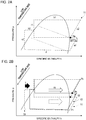
- Refrigeration cycles of the refrigerant circuit 10 are shown in FIGS. 2A and 2B .
- a refrigeration cycle Y1 when control for mitigating the decrease in the evaporator inlet temperature, to be described later, is not executed by the controller 20 is represented by the dashed lines.
- a refrigeration cycle Y2 when the control for mitigating the decrease in the evaporator inlet temperature, to be described later, is executed by the controller 20 is represented by the solid lines.
- a compression process in the refrigeration cycle Y1 consists of a compression process a1 by the low-stage compressor 11 and a compression process a2 by the high-stage compressor 12.
- the pressure at a border between the compression process a1 and the compression process a2 corresponds to the intermediate pressure Pm that is supplied to the high-stage compressor 12 by the intermediate pressure injection part 30.
- the temperature of the refrigerant suctioned into the compression mechanism of the high-stage compressor 12 decreases by an amount corresponding to ⁇ h1.
- the refrigerant having been compressed by the low-stage compressor 11 and the high-stage compressor 12 undergoes a condensation process b1 by a condenser (e.g., the second heat exchanger 14), and is further condensed as the heat thereof is absorbed in the internal heat exchanger 32 by part of the refrigerant that has been depressurized. Then, in the example shown in FIG. 2A , the refrigerant is supercooled (b2).
- a condenser e.g., the second heat exchanger 14
- a depressurization process of the refrigeration cycle Y1 consists of a depressurization process c1 by the second depressurization part 31 and a depressurization process c2 by the first depressurization part 15.
- the refrigerant having undergone the depressurization process c2 undergoes an evaporation process d by an evaporator (e.g., the first heat exchanger 13) and reaches the compression process a1.
- an evaporator e.g., the first heat exchanger 13
- the controller 20 ( FIG. 1 ) controls operations of elements included in the refrigerant circuit 10, such as various valves including the depressurization parts 15, 31, and the compressors 11, 12, by using measurement values of temperatures, pressures, etc. detected by various sensors and set values of temperatures, pressures, etc. that are specified in advance.
- the controller 20 is applied to the refrigerant circuit 10 including the low-stage compressor 11 and the high-stage compressor 12 that are connected in series, and the intermediate pressure injection part 30 that supplies the high-stage compressor 12 with the refrigerant at the intermediate pressure Pm.
- the controller 20 that controls the refrigerant circuit 10 sends a command to the second depressurization part 31, which is an expansion valve or the like, according to fluctuations in the heat load, an operation status, etc., and can thereby adjust the amount (injection amount) of the refrigerant supplied to the high-stage compressor 12 by the intermediate pressure injection part 30.
- Such control is similar to control by a typical controller used for a refrigerant circuit that supplies the high-stage compressor 12 with a refrigerant at the intermediate pressure Pm.
- the controller 20 of the embodiment controls the rotation speed of the compression mechanism of each of the low-stage compressor 11 and the high-stage compressor 12 based on an index that indicates the evaporator inlet temperature.
- the "evaporator inlet temperature” corresponds to the temperature of the refrigerant at a start point of the evaporation process by either the first heat exchanger 13 or the second heat exchanger 14.
- a high pressure Ph that is a pressure at a condenser (corresponding to the pressure of the refrigerant discharged from the high-stage compressor 12) and a low pressure Pl that is a pressure at an evaporator (corresponding to the pressure of the refrigerant suctioned into the low-stage compressor 11) are set.
- the intermediate pressure Pm is set in addition to the high pressure Ph and the low pressure Pl.
- the intermediate pressure Pm is typically set to a middle value between the high pressure Ph and the low pressure Pl, or a value close to the middle value.
- the controller 20 executes feedback control on the rotation speed of the high-stage compressor 12 based on the high pressure Ph and executes feedback control on the rotation speed of the low-stage compressor 11 based on the intermediate pressure Pm.
- the controller 20 increases the rotation speed of the low-stage compressor 11 when it is necessary to suppress the decrease in the evaporator inlet temperature based on an index X indicating the evaporator inlet temperature.
- the rotation speed of the high-stage compressor 12 decreases as will be described later.
- the rotation speed ratio between the compressors 11, 12 changes from that at normal times.
- the rotation speed control of the low-stage compressor 11 and the high-stage compressor 12 executed to suppress the decrease in the evaporator inlet temperature be executed prior to the control of the second depressurization part 31 etc. so as not to affect the performance of the refrigeration cycle device 1. This will be described later.
- the controller 20 uses the index X indicating the temperature at the evaporator inlet. This index X is specified using a temperature sensor 17 that detects the evaporator inlet temperature.
- the temperature sensor 17 is mounted near an inlet of the first heat exchanger 13 that functions as an evaporator during heating operation. For the purpose of mitigating formation of frost on the evaporator during heating operation, it suffices to mount the temperature sensor 17 near the inlet of the first heat exchanger 13.
- the index X is also possible to specify the index X using a temperature detected by a temperature sensor (air temperature sensor) that detects the temperature of an atmosphere (outside air) near the evaporator, instead of the temperature sensor 17.
- a temperature sensor air temperature sensor
- a pressure sensor that detects the pressure of the refrigerant at the evaporator inlet can be mounted near the inlet of the evaporator.
- the index X can be specified using a pressure detected by this pressure sensor. Since the pressure sensor directly detects the temperature of the refrigerant inside the evaporator, the index X that appropriately indicates the refrigerant temperature at the evaporator inlet can be specified, compared with when a temperature sensor that is usually mounted on an outer side of an evaporator and detects the temperature of a refrigerant through a member of the evaporator is used.
- the index X may also be specified using two or more of the temperature sensor 17, the air temperature sensor, and the pressure sensor.
- the temperature and the dryness of the refrigerant at an outlet of the evaporator can also be used to specify the index X.
- the index X can be specified in advance based on tests performed by operating the refrigeration cycle device 1, simulations, etc.
- the index X may be stored in a storage unit 21 of the controller 20, and the index X may be retrieved from the storage unit 21 to be used for control.
- the controller 20 can be configured as a computer including a calculation unit 22 and the storage unit 21. In this case, creating a computer program corresponding to control executed by the controller 20 and running this computer program can realize the control executed by the controller 20.
- Control by the controller 20 when the evaporator inlet temperature decreases will be described with reference to FIG. 3 , FIG. 2A and FIG. 2B .
- This control is equivalent to control for mitigating formation of frost on the evaporator during heating operation.
- the controller 20 determines whether it is necessary to suppress the decrease in the evaporator inlet temperature based on the index X indicating the evaporator inlet temperature (determination step S1). For example, when the temperature detected by the temperature sensor 17 is the index X, it is determined to be necessary to suppress the decrease in the evaporator inlet temperature if the temperature detected by the temperature sensor 17 is equal to or lower than a threshold value.
- step S2 When it is determined to be necessary to suppress the decrease in the evaporator inlet temperature by the determination step S1 (Yes in step S1), the rotation speed of the low-stage compressor 11 is increased (rotation speed control step S2).
- the temperature may be repeatedly measured by the temperature sensor 17 during a certain period of time, and when the measured value of the temperature exceeds a reference a predetermined number of times or more, the controller 20 may move to step S2 and the subsequent steps.
- the controller 20 increases a target value for the intermediate pressure Pm and executes feedback control on the rotation speed of the low-stage compressor 11 such that the intermediate pressure Pm meets the target value, and thereby increases the rotation speed of the low-stage compressor 11. This is for the following reasons.
- the intermediate pressure Pm increases, so that the temperature of the refrigerant increases, so that the opening of the second depressurization part 31 is reduced and the injection amount decreases as described above.
- the injection amount decreases, the enthalpy at the evaporator inlet increases, causing a rise in the evaporator inlet temperature.
- the flow rate of the refrigerant flowing through the evaporator increases.
- the low pressure Pl the suction pressure of the low-stage compressor 11
- the rotation speed of the low-stage compressor 11 is increased to increase the circulation amount of the refrigerant.
- the high pressure Ph does not change and the circulation amount of the refrigerant does not change.
- the intermediate pressure Pm supplied to the high-stage compressor 12 by the intermediate pressure injection part 30 the density of the refrigerant suctioned into the high-stage compressor 12 increases. Therefore, the rotation speed of the high-stage compressor 12 needs to be reduced in order to maintain the same circulation amount.
- step S2 feedback control is executed on the rotation speed of the high-stage compressor 12 by the controller 20 so as to maintain a constant high pressure Ph, so that the rotation speed of the high-stage compressor 12 decreases.
- the refrigeration cycle of the refrigerant circuit 10 changes from the state (Y1) represented by the dashed lines to the state (Y2) represented by the solid lines as shown in FIG. 2B .
- step S1 when it is determined to be necessary to suppress the decrease in the evaporator inlet temperature based on the index X (Yes in step S1), the controller 20 increases the target value for the intermediate pressure Pm and increases the rotation speed of the low-stage compressor 11 (step S2). Then, the intermediate pressure Pm increases, and as described above, the rotation speed of the high-stage compressor 12 decreases while the low pressure Pl and the high pressure Ph remain the same.
- an injection amount IN (represented by the thickness of the outlined arrow in FIG. 2B ) decreases.
- the control of the embodiment can raise the evaporator inlet temperature compared with the case represented by the dashed lines in FIG. 2B in which the control for mitigating the decrease in the evaporator inlet temperature is not executed.
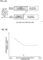
- FIG. 4A shows a difference in a temperature region of formation of frost on the evaporator according to with or without the above-described control for mitigating the decrease in the evaporator inlet temperature.
- the controller 20 may return to the control for normal times, for example, when the index X exceeds a predetermined threshold value.
- the threshold value in this case can be set to be larger than the threshold value at which the controller 20 shifts from the control for normal times to the control for mitigating the decrease in the evaporator inlet temperature.
- the controller 20 may return to the control for normal times regardless of the index X when a predetermined time has elapsed after the controller 20 shifts to the control for mitigating the decrease in the evaporator inlet temperature.
- Similar control may be performed when the controller 20 is set to a predetermined mode for mitigating the decrease in the evaporator inlet temperature. Specifically, when the controller 20 is set to this mode, the controller 20 increases the target value for the intermediate pressure Pm and controls the rotation speed of the low-stage compressor 11 such that the intermediate pressure Pm meets the target value. In this case, the rotation speed of the low-stage compressor 11 increases while the rotation speed of the high-stage compressor 12 decreases. Then, the injection amount decreases, which can suppress the decrease in the evaporator inlet temperature.
- the refrigerant circuit 10 of the refrigeration cycle device 1 of the embodiment can be configured just like an existing refrigerant circuit of the same type, without any addition of a constituent element to a refrigerant circuit of the same type that has the two-stage compressors 11, 12 and the intermediate pressure injection part 30. There is no need to divide the evaporator and add an expansion valve.
- controller 20 of the refrigeration cycle device 1 can be configured simply by adding, to basic control of a controller that is applied to a refrigerant circuit of the same type as the refrigerant circuit 10, the control of increasing the intermediate pressure Pm and increasing the rotation speed of the low-stage compressor 11 when it is necessary to suppress the decrease in the evaporator inlet temperature.
- the refrigeration cycle device 1 can suppress the decrease in the inlet temperature of the evaporator due to a temperature glide attributable to a zeotropic refrigerant, and suppress formation of frost on the evaporator during heating operation, while keeping costs down by being able to use an existing refrigerant circuit 10.
- controlling the flow rate in the second depressurization part 31 so as to reduce the injection amount can also suppress the decrease in the temperature at the evaporator inlet.
- the temperature of the secondary refrigerant at the outlet of the internal heat exchanger 32 rises due to an increase in the flow rate of the primary refrigerant corresponding to the amount of decrease in the injection amount, and if the intermediate pressure Pm remains the same, the temperature of the refrigerant suctioned into the high-stage compressor 12 may rise excessively.
- the performance may degrade temporarily during a process in which the control of the rotation speeds of the compressors 11, 12 responds to the decrease in the injection amount due to the control of the second depressurization part 31.
- the rotation speeds of the compressors 11, 12 are controlled before the injection amount is reduced by the control of the second depressurization part 31.
- the rotation speed of the high-stage compressor 12 is controlled so as to maintain the high pressure Ph. Therefore, required predetermined performance of the refrigeration cycle device 1 can be secured without the performance thereof being affected. Moreover, the temperature of the refrigerant suctioned into the high-stage compressor 12 can be kept down to secure the reliability.
- the target value for the intermediate pressure When increasing the target value for the intermediate pressure, it can be increased to a fixed pressure, or to a variable pressure that is specified according to predetermined conditions. Or the target value can be increased to a pressure obtained by adding a fixed increase amount or a variable increase amount to a current intermediate pressure target value.
- the degree of necessity of mitigating the decrease in the evaporator inlet temperature can be said to change according to the index X. From this perspective, it is preferable that when increasing the target value for the intermediate pressure, the target value be set to a value corresponding to the index X that is variable.
- FIG. 4B shows a correspondence relationship between the index X and the intermediate pressure target value when the index X is the temperature detected by the temperature sensor 17 that detects the evaporator inlet temperature.
- required refrigeration performance is constant.
- the intermediate pressure target value is set such that the intermediate pressure target value varies according to the index X, in this example, the target value becomes higher as the index X becomes lower.
- the intermediate pressure target value is higher, the intermediate pressure Pm increases further and the injection amount decreases further accordingly.
- controlling the rotation speeds of the compressors 11, 12 while giving the controller 20 an intermediate pressure target value corresponding to the index X allows efficient operation of the refrigeration cycle device 1 while reliably mitigating the decrease in the evaporator inlet temperature.
- the index X and the intermediate pressure target value be stored in the storage unit 21 of the controller 20, so as to correspond to each other, over a predetermined variable range of the index X.
- the rotation speeds of the compressors 11, 12 be controlled while an intermediate pressure target value corresponding to the varying index X is given to the controller 20, also after the controller 20 is set to the predetermined mode for mitigating the decrease in the evaporator inlet temperature.
- a receiver 34 (second depressurization part) is used as a mechanism that supplies the high-stage compressor 12 with the refrigerant at an intermediate pressure.
- the receiver 34 is integrated in the refrigerant circuit 10 in place of the second depressurization part 31 and the internal heat exchanger 32.
- the receiver 34 receives and stores a high-pressure liquid refrigerant having undergone the condensation process, and depressurizes this refrigerant.
- the pressure of the refrigerant having flowed into the receiver 34 is reduced inside the receiver 34.
- the refrigerant is separated into a liquid and a gas due to the difference in density between a liquid phase and a gas phase of the refrigerant.
- the gas refrigerant inside the receiver 34 is supplied to the high-stage compressor 12.
- the intermediate pressure target value is increased and the rotation speed of the low-stage compressor 11 is controlled (increased) such that the intermediate pressure Pm meets the intermediate pressure target value.
- the intermediate pressure Pm increases, so that the amount, i.e., the injection amount, of the refrigerant supplied from the receiver 34 to the high-stage compressor 12 based on the pressure difference between the inside of the receiver 34 and the intermediate pressure Pm decreases. Accordingly, the decrease in the evaporator inlet temperature can be suppressed.
- the refrigeration cycle device of the present invention is not limited to one that is used for both heating and cooling a heat load but may be configured exclusively for heating or exclusively for cooling. In this case, the four-way valve 16 is not required.
- a low-stage-side first compression mechanism and a high-stage-side second compression mechanism are disposed inside a housing of one compressor and an intermediate-pressure refrigerant is supplied to between the first compression mechanism and the second compression mechanism.
- the controller 20 can be applied also to a refrigerant circuit including such a compressor.
- the present invention can be applied also to a refrigerant circuit that includes three or more compressors connected in series and that is configured such that a refrigerant at an intermediate pressure is supplied to at least one of the compressors.
Landscapes
- Engineering & Computer Science (AREA)
- Physics & Mathematics (AREA)
- Mechanical Engineering (AREA)
- Thermal Sciences (AREA)
- General Engineering & Computer Science (AREA)
- Compression-Type Refrigeration Machines With Reversible Cycles (AREA)
- Devices That Are Associated With Refrigeration Equipment (AREA)
Abstract
Description
- The present invention relates to a refrigeration cycle device including a refrigerant circuit through which a refrigerant flows, and a method for controlling the refrigeration cycle device.
- In recent years, a shift toward refrigerants with low global warming potentials (GWPs) has been in progress to reduce environmental burden. Representative examples of low-GWP refrigerants include HF0-1234yf that was developed as an alternative refrigerant for HFC-134a.
- However, when a single-component refrigerant with a low GWP, such as HF0-1234yf, is used, the pressure obtained by a refrigerant circuit tends to be low. Therefore, to supplement the pressure, a low-GWP refrigerant, such as HF0-1234yf, is sometimes used by being mixed with a refrigerant, for example, R32.
- A mixture of two or more types of refrigerants having different boiling points like HF0-1234yf and R32 is called a zeotropic refrigerant. It is known that when a single-component refrigerant is used, the temperature of the refrigerant remains constant during a condensation process and an evaporation process, whereas when a zeotropic refrigerant is used, the temperature of the refrigerant changes during a condensation process and an evaporation process. This change in the refrigerant temperature is called a temperature glide.
- In
FIG. 6A , an evaporation process when a single-component refrigerant is used is represented by the dashed line. InFIG. 6B , an evaporation process when a zeotropic refrigerant is used is represented by the dashed line. In each ofFIGS. 6A and 6B , isothermal lines of equal refrigerant temperatures are represented by the long dashed short dashed lines. In each ofFIGS. 6A and 6B , an evaporator inlet is represented by a circle surrounding it. - When a zeotropic refrigerant is used, the refrigerant temperature tends to be lower closer to the evaporator inlet due to the temperature glide. Therefore, when a zeotropic refrigerant is used, formation of frost on the evaporator occurs during heating operation, such as space heating, even at a higher outside air temperature compared with when a single-component refrigerant is used.
- In
Patent Literature 1, to suppress the decrease in the inlet temperature of an evaporator due to a temperature glide of a zeotropic refrigerant, a second expansion valve is disposed in the middle of an evaporation process, separately from a first expansion valve that is located upstream of the evaporator. The refrigerant temperature is lowered and an average evaporation temperature is raised by this second expansion valve to thereby raise the inlet temperature of the evaporator and suppress frost formation. - Patent Literature 1:
JP 2009-222357 A - The method of
Patent Literature 1 involves not only a device cost for the second expansion valve but also a cost required to divide the evaporator so as to dispose the second expansion valve in the evaporation process, which adds to manufacturing costs related mainly to devices. - It is therefore desirable to achieve a solution by control of the refrigerant circuit, with as few changes as possible made to the devices.
- Thus, regarding a refrigerant circuit using a zeotropic refrigerant, the present invention aims to provide a refrigeration cycle device that can suppress the decrease in the inlet temperature of an evaporator due to a temperature glide while keeping costs down, and a method for controlling this refrigeration cycle device.
- A refrigeration cycle device of the present invention includes a refrigerant circuit through which a zeotropic refrigerant flows, and a controller that controls elements composing the refrigerant circuit.
- The refrigerant circuit has: a first compression mechanism and a second compression mechanism that are connected in series and compress the refrigerant; a first heat exchanger that exchanges heat between a heat source and the refrigerant; a first depressurization part that reduces a pressure of the refrigerant; a second heat exchanger that exchanges heat between a heat load and the refrigerant; and an intermediate pressure supply part that supplies the second compression mechanism with the refrigerant at an intermediate pressure that is reduced with respect to a pressure of the refrigerant having undergone a condensation process by either the first heat exchanger or the second heat exchanger.
- In the present invention, the controller controls operating speeds of the first compression mechanism and the second compression mechanism based on an index indicating an evaporator inlet temperature that is a temperature at a start point of an evaporation process by either the first heat exchanger or the second heat exchanger, or controls the operating speeds of the first compression mechanism and the second compression mechanism when a predetermined mode for mitigating a decrease in the evaporator inlet temperature is set.
- In the refrigeration cycle device of the present invention, it is preferable that the refrigerant circuit further have: a second depressurization part that reduces a pressure of part of the refrigerant that has undergone the condensation process; and an internal heat exchanger that cools a primary refrigerant having a higher pressure than the intermediate pressure by exchanging heat between the primary refrigerant and a secondary refrigerant that is reduced in pressure by the second depressurization part, and that the intermediate pressure supply part supply the second compression mechanism with the secondary refrigerant having passed through the internal heat exchanger.
- In the refrigeration cycle device of the present invention, it is preferable that the refrigerant circuit further have a second depressurization part that stores and depressurizes the refrigerant having undergone the condensation process.
- In the refrigeration cycle device of the present invention, it is preferable that the refrigeration cycle device be capable of heating operation of heating the heat load by the refrigerant circuit, and that, during the heating operation, the first heat exchanger function as an evaporator and the second heat exchanger function as a condenser.
- In the refrigeration cycle device of the present invention, it is preferable that the controller increase a target value for the intermediate pressure and control the operating speed of the first compression mechanism such that the intermediate pressure meets the target value.
- In the refrigeration cycle device of the present invention, it is preferable that the controller have a storage unit that stores the index and the target value, so as to correspond to each other, over a predetermined variable range of the index.
- In the refrigeration cycle device of the present invention, it is preferable that the refrigerant circuit further have at least one of the following: a temperature sensor that detects the evaporator inlet temperature; an air temperature sensor that detects a temperature of an atmosphere near an evaporator; and a pressure sensor that detects a pressure of the refrigerant at a start point of the evaporation process, and that the index be specified using at least one of a temperature detected by the temperature sensor, a temperature detected by the air temperature sensor, and a pressure detected by the pressure sensor.
- Further, the present invention is a method for controlling a refrigeration cycle device including a refrigerant circuit that is a circuit through which a zeotropic refrigerant flows and has a first compression mechanism, a second compression mechanism, and an intermediate pressure supply part that supplies the second compression mechanism with the refrigerant at an intermediate pressure that is reduced with respect to a pressure of the refrigerant having undergone a condensation process. The method includes: a determination step of determining, based on an index indicating an evaporator inlet temperature that is a temperature at a start point of an evaporation process, whether it is necessary to suppress a decrease in the evaporator inlet temperature; and a control step of controlling operating speeds of the first compression mechanism and the second compression mechanism when it is determined to be necessary to suppress a decrease in the evaporator inlet temperature.
- Furthermore, the present invention is a method for controlling a refrigeration cycle device including a refrigerant circuit that is a circuit through which a zeotropic refrigerant flows and has a first compression mechanism, a second compression mechanism, and an intermediate pressure supply part that supplies the second compression mechanism with the refrigerant at an intermediate pressure that is reduced with respect to a pressure of the refrigerant having undergone a condensation process. The method includes a control step of controlling operating speeds of the first compression mechanism and the second compression mechanism when a predetermined mode for mitigating a decrease in an evaporator inlet temperature that is a temperature at a start point of an evaporation process is set.
- In the control method of the present invention, it is preferable that, in the control step, a target value for the intermediate pressure be increased and the operating speed of the first compression mechanism be controlled such that the intermediate pressure meets the target value.
- In the control method of the present invention, it is preferable that, in the control step, a target value for the intermediate pressure be set to a value according to the index that is variable, and that the operating speed of the first compression mechanism be controlled such that the intermediate pressure meets the target value.
- The refrigerant circuit included in the refrigeration cycle device of the present invention can be configured just like an existing refrigerant circuit of the same type, without any addition of a constituent element to a refrigerant circuit of the same type that includes two stages of compressors and performs injection of an intermediate pressure.
- Further, in the present invention, as will be described in detail later, when it is necessary to suppress the decrease in the evaporator inlet temperature, increasing the intermediate pressure and controlling the rotation speed of the first compressor can reduce the injection amount and raise the evaporator inlet temperature without affecting the refrigeration performance.
- Thus, it is possible to suppress the decrease in the evaporator inlet temperature that tends to decrease due to use of a zeotropic refrigerant, and to suppress formation of frost on the evaporator during heating operation, while keeping costs down and securing performance.
-
- [
FIG. 1] FIG. 1 is a view schematically showing a refrigeration cycle device according to an embodiment of the present invention. "Evaporation process" and "condensation process" are indicated based on those during heating operation. - [
FIG. 2] FIG. 2A and FIG. 2B are p-h charts according to the embodiment of the present invention,FIG. 2A showing a refrigeration cycle without control for mitigating a decrease in an evaporator inlet temperature by the dashed lines, andFIG. 2B showing, in addition to the refrigeration cycle without the control for mitigating the decrease in the evaporator inlet temperature, a refrigeration cycle with the control for mitigating the decrease in the evaporator inlet temperature by the solid lines. - [
FIG. 3] FIG. 3 is a chart showing a procedure of the control for mitigating the decrease in the evaporator inlet temperature according to the embodiment of the present invention. - [
FIG. 4] FIG. 4A is a schematic view illustrating a frost formation mitigating effect of the control for mitigating the decrease in the evaporator inlet temperature.FIG. 4B is a graph showing a correspondence relationship between an index indicating the evaporator inlet temperature and a target value for an intermediate pressure. - [
FIG. 5] FIG. 5 is a view schematically showing a refrigeration cycle device according to a modified example of the present invention. "Evaporation process" and "condensation process" are indicated based on those during heating operation. - [
FIG. 6] FIG. 6A is a chart showing a refrigerant temperature trend when a single-component refrigerant is used, andFIG. 6B is a chart showing a refrigerant temperature trend when a zeotropic refrigerant is used. - An embodiment of the present invention will be described below with reference to the accompanying drawings.
- A
refrigeration cycle device 1 shown inFIG. 1 includes arefrigerant circuit 10 through which a zeotropic refrigerant flows and acontroller 20 that controls therefrigerant circuit 10. - The
refrigeration cycle device 1 can be configured as various devices including a refrigerant circuit through which a refrigerant flows, for example, as an air conditioner, a refrigerator, a water heater, and a heat pump. - A zeotropic refrigerant refers to a mixture of two or more types of refrigerants having different boiling points. For example, a mixture of HF0-1234yf and R32 falls under the category of a zeotropic refrigerant. Other examples of zeotropic refrigerants include a refrigerant mixture of HF0-1234ze and R32 and a refrigerant mixture of hydrocarbon and R32.
- The zeotropic refrigerant (hereinafter referred to simply as the refrigerant) is enclosed in the
refrigerant circuit 10 at a predetermined mixing ratio and circulates through therefrigerant circuit 10. - Due to a temperature glide of the zeotropic refrigerant in an evaporation process (
FIG. 6B ), the temperature of the refrigerant at an evaporator inlet tends to be low compared with when a single-component refrigerant is used (FIG. 6A ). - The decrease in the refrigerant temperature at the inlet of the evaporator can be suppressed by control performed by the
controller 20 of the embodiment. Thus, during heating operation of therefrigeration cycle device 1, occurrence of formation of frost on the evaporator can be suppressed. - The refrigerant circuit 10 (
FIG. 1 ) has a low-stage compressor 11 (first compression mechanism), a high-stage compressor 12 (second compression mechanism), twoheat exchangers 13, 14 (a first heat exchanger and a second heat exchanger), afirst depressurization part 15, an intermediate pressure injection part 30 (an intermediate pressure supply part) including asecond depressurization part 31, and a four-way valve 16. - The
refrigerant circuit 10 can perform both cooling operation and heating operation as a flow direction of the refrigerant is switched by the four-way valve 16. - In
FIG. 1 , a direction in which the refrigerant flows through therefrigerant circuit 10 during heating operation is indicated by arrows. - The
refrigeration cycle device 1 cools or heats a heat load using outside air as a heat source, by a refrigeration cycle consisting of processes of expansion and evaporation due to compression, condensation, and depressurization of the refrigerant flowing through therefrigerant circuit 10. - The
refrigeration cycle device 1 may be configured such that the performance can be varied according to the fluctuating heat load, or may be configured to have constant performance regardless of the heat load. - The
refrigerant circuit 10 has themulti-stage compressors pressure injection part 30 between thecompressors refrigerant circuit 10 can secure compression efficiency and keep down the temperature of the refrigerant discharged from the compressors. - The configuration of the
refrigerant circuit 10 is equivalent to a configuration typical of a refrigerant circuit of the same type that includes the low-stage compressor 11, the high-stage compressor 12, and the intermediatepressure injection part 30. Therefrigerant circuit 10 of the embodiment can be composed only of constituent elements that are included in a refrigerant circuit of the same type. - Each of the low-
stage compressor 11 and the high-stage compressor 12 compresses the refrigerant by rotating scrolls or a rotary piston or moving vanes back and forth using a power source, such as an electric motor. - The low-
stage compressor 11 includes an appropriate compression mechanism (not shown), for example, a scroll compression mechanism, and ahousing 111 that houses the compression mechanism. The low-stage compressor 11 may include a plurality of compression mechanisms inside thehousing 111. - Similarly, the high-
stage compressor 12 includes an appropriate compression mechanism (not shown), for example, a scroll compression mechanism, and ahousing 121 that houses the compression mechanism. The high-stage compressor 12 may include a plurality of compression mechanisms inside thehousing 121. - Each of the low-
stage compressor 11 and the high-stage compressor 12 is configured such that the operating speed of the compression mechanism can be varied based on a command from thecontroller 20. For example, in the case of an electric scroll compressor having a motor as a power source, the rotation speed of the scroll is controlled as a driving current generated by a driving device provided in the compressor is applied to the motor based on a command indicating the rotation speed of the scroll. - Hereinafter, the operating speed will be referred to as the rotation speed based on the assumption of a compression mechanism that compresses a refrigerant by rotary motion.
- The refrigerant compressed by the low-
stage compressor 11 is suctioned into the high-stage compressor 12 and compressed to a higher pressure. Adischarge part 11B through which the refrigerant is discharged from the low-stage compressor 11 and anintroduction part 12A through which the refrigerant is introduced into the high-stage compressor 12 are connected to each other by apipe 120. - The
first heat exchanger 13 exchanges heat between outside air that is a heat source and the refrigerant. Thefirst heat exchanger 13 functions as a condenser during cooling operation and functions as an evaporator during heating operation. - The
second heat exchanger 14 exchanges heat between air, water, or the like that is a heat load and the refrigerant. Thesecond heat exchanger 14 functions as an evaporator during cooling operation and functions as a condenser during heating operation. - For the first and
second heat exchangers FIG. 1 , the processes (evaporation process/condensation process) of which the respective heat exchangers are in charge during heating operation are indicated. - The
first depressurization part 15 reduces the pressure of the refrigerant having undergone the condensation process. As thefirst depressurization part 15, an expansion valve, a capillary tube, or the like can be used. - During each of heating operation and cooling operation, the intermediate
pressure injection part 30 supplies thesecond compressor 12 with the refrigerant at the intermediate pressure Pm that is reduced with respect to the pressure of the refrigerant having undergone the condensation process. - The intermediate
pressure injection part 30 of the embodiment includes thesecond depressurization part 31 and aninternal heat exchanger 32. - The
second depressurization part 31 reduces the pressure of part of the refrigerant having undergone the condensation process and supplies the refrigerant to theinternal heat exchanger 32. The refrigerant that has undergone the condensation process in thefirst heat exchanger 13 or thesecond heat exchanger 14 flows through aninjection flow passage 33 toward thesecond compressor 12 via thesecond depressurization part 31 and theinternal heat exchanger 32. - As the
second depressurization part 31, an expansion valve, a combination of a capillary tube and a valve, or the like can be used. - The
second depressurization part 31 is typically an expansion valve, and an extent of closing thereof is controlled in accordance with a command from thecontroller 20. - The
internal heat exchanger 32 performs heat exchange between a primary refrigerant that, after undergoing the condensation process, flows toward thefirst depressurization part 15 without flowing into thesecond depressurization part 31, and a secondary refrigerant of which the pressure is reduced by thesecond depressurization part 31, and thereby cools the primary refrigerant. - Compared with the primary refrigerant flowing through the
internal heat exchanger 32, the secondary refrigerant of which the pressure has been reduced by thesecond depressurization part 31 has a low pressure and a low temperature. Therefore, in theinternal heat exchanger 32, the primary refrigerant flowing through the path indicated by the solid line and the secondary refrigerant flowing through the path indicated by the dashed line give and receive heat to and from each other based on a temperature difference. In theinternal heat exchanger 32, heat exchange is basically performed between the primary refrigerant that is a high-pressure fluid and the secondary refrigerant that is a low-pressure gas. The secondary refrigerant that is further gasified by absorbing heat from the primary refrigerant in theinternal heat exchanger 32 is supplied to thesecond compressor 12. - The amount (injection amount) of the refrigerant supplied to the
second compressor 12 through thesecond depressurization part 31 and theinternal heat exchanger 32 can be adjusted by controlling thesecond depressurization part 31 and thereby adjusting the flow rate of the refrigerant flowing into thesecond depressurization part 31. - The efficiency of heat exchange in the
internal heat exchanger 32 depends on the temperature difference between the primary refrigerant and the secondary refrigerant; therefore, thecontroller 20 reduces the opening of thesecond depressurization part 31 and reduces the injection amount when the temperature of the secondary refrigerant rises. Thesecond depressurization part 31 may be fully closed. When the temperature difference between the primary refrigerant and the secondary refrigerant is small, the secondary refrigerant may be supplied to the high-stage compressor 12 without being sufficiently gasified in theinternal heat exchanger 32. Also to avoid this, thecontroller 20 reduces the opening of thesecond depressurization part 31 and reduces the injection amount. - The temperature of the secondary refrigerant rises as the pressure (the intermediate pressure Pm) of the refrigerant supplied to the high-
stage compressor 12 increases. Therefore, when the intermediate pressure Pm detected by apressure sensor 18 located between the low-stage compressor 11 and the high-stage compressor 12 is higher, thecontroller 20 further reduces the injection amount by reducing the opening of thesecond depressurization part 31. As the injection amount decreases, the amount of the refrigerant flowing from the condenser to thefirst depressurization part 15 increases accordingly. - The intermediate
pressure injection part 30 of the embodiment sprays the refrigerant at an intermediate pressure into thepipe 120 connecting the low-stage compressor 11 and the high-stage compressor 12 to each other, and thereby supplies the refrigerant at the intermediate pressure Pm, along with the refrigerant discharged from the low-stage compressor 11, into thehousing 121 of the high-stage compressor 12. - However, it is also possible to configure the intermediate
pressure injection part 30 so as to supply the refrigerant at the intermediate pressure to thesecond compressor 12, separately from the refrigerant discharged from the low-stage compressor 11. - Refrigeration cycles of the
refrigerant circuit 10 are shown inFIGS. 2A and 2B . - In
FIG. 2A , a refrigeration cycle Y1 when control for mitigating the decrease in the evaporator inlet temperature, to be described later, is not executed by thecontroller 20 is represented by the dashed lines. - In
FIG. 2B , in addition to the refrigeration cycle Y1, a refrigeration cycle Y2 when the control for mitigating the decrease in the evaporator inlet temperature, to be described later, is executed by thecontroller 20 is represented by the solid lines. - First, the refrigeration cycle Y1 shown in
FIG. 2A will be described. - A compression process in the refrigeration cycle Y1 consists of a compression process a1 by the low-
stage compressor 11 and a compression process a2 by the high-stage compressor 12. - Here, the pressure at a border between the compression process a1 and the compression process a2 corresponds to the intermediate pressure Pm that is supplied to the high-
stage compressor 12 by the intermediatepressure injection part 30. As the refrigerant discharged from the low-stage compressor 11 is cooled by the refrigerant at the intermediate pressure Pm, the temperature of the refrigerant suctioned into the compression mechanism of the high-stage compressor 12 decreases by an amount corresponding to Δh1. - The refrigerant having been compressed by the low-
stage compressor 11 and the high-stage compressor 12 undergoes a condensation process b1 by a condenser (e.g., the second heat exchanger 14), and is further condensed as the heat thereof is absorbed in theinternal heat exchanger 32 by part of the refrigerant that has been depressurized. Then, in the example shown inFIG. 2A , the refrigerant is supercooled (b2). - When the condensation process consisting of the condensation process b1, and a condensation process b2 by the
internal heat exchanger 32 is ended, the pressure of the refrigerant is reduced by the first depressurization part 15 (c2). A depressurization process of the refrigeration cycle Y1 consists of a depressurization process c1 by thesecond depressurization part 31 and a depressurization process c2 by thefirst depressurization part 15. - The refrigerant having undergone the depressurization process c2 undergoes an evaporation process d by an evaporator (e.g., the first heat exchanger 13) and reaches the compression process a1.
- The controller 20 (
FIG. 1 ) controls operations of elements included in therefrigerant circuit 10, such as various valves including thedepressurization parts compressors - The
controller 20 is applied to therefrigerant circuit 10 including the low-stage compressor 11 and the high-stage compressor 12 that are connected in series, and the intermediatepressure injection part 30 that supplies the high-stage compressor 12 with the refrigerant at the intermediate pressure Pm. - The
controller 20 that controls therefrigerant circuit 10 sends a command to thesecond depressurization part 31, which is an expansion valve or the like, according to fluctuations in the heat load, an operation status, etc., and can thereby adjust the amount (injection amount) of the refrigerant supplied to the high-stage compressor 12 by the intermediatepressure injection part 30. Such control is similar to control by a typical controller used for a refrigerant circuit that supplies the high-stage compressor 12 with a refrigerant at the intermediate pressure Pm. - As described above, when a zeotropic refrigerant mixture is used, the inlet temperature of the evaporator tends to decrease compared with when a single-component refrigerant is used. To suppress such a decrease in the evaporator inlet temperature and suppress formation of frost on the evaporator especially during heating operation, the
controller 20 of the embodiment controls the rotation speed of the compression mechanism of each of the low-stage compressor 11 and the high-stage compressor 12 based on an index that indicates the evaporator inlet temperature. - The "evaporator inlet temperature" corresponds to the temperature of the refrigerant at a start point of the evaporation process by either the
first heat exchanger 13 or thesecond heat exchanger 14. - Here, for controllers used for refrigerant circuits in general, a high pressure Ph that is a pressure at a condenser (corresponding to the pressure of the refrigerant discharged from the high-stage compressor 12) and a low pressure Pl that is a pressure at an evaporator (corresponding to the pressure of the refrigerant suctioned into the low-stage compressor 11) are set. In a case where an intermediate-pressure refrigerant is supplied to the high-
stage compressor 12, the intermediate pressure Pm is set in addition to the high pressure Ph and the low pressure Pl. The intermediate pressure Pm is typically set to a middle value between the high pressure Ph and the low pressure Pl, or a value close to the middle value. Thecontroller 20 executes feedback control on the rotation speed of the high-stage compressor 12 based on the high pressure Ph and executes feedback control on the rotation speed of the low-stage compressor 11 based on the intermediate pressure Pm. - At normal times, a balance between the rotation speed of the low-
stage compressor 11 and the rotation speed of the high-stage compressor 12 is maintained at a predetermined ratio under control by thecontroller 20. - As described above, while executing basic control of the
refrigerant circuit 10, including the control for adjusting the injection amount by thesecond depressurization part 31 and the rotation speed control of thecompressors controller 20 increases the rotation speed of the low-stage compressor 11 when it is necessary to suppress the decrease in the evaporator inlet temperature based on an index X indicating the evaporator inlet temperature. As a result, the rotation speed of the high-stage compressor 12 decreases as will be described later. Thus, as a result of increasing the rotation speed of the low-stage compressor 11, the rotation speed ratio between thecompressors stage compressor 11 and the high-stage compressor 12 executed to suppress the decrease in the evaporator inlet temperature be executed prior to the control of thesecond depressurization part 31 etc. so as not to affect the performance of therefrigeration cycle device 1. This will be described later. - To execute the control for mitigating the decrease in the inlet temperature of the evaporator, the
controller 20 uses the index X indicating the temperature at the evaporator inlet. This index X is specified using atemperature sensor 17 that detects the evaporator inlet temperature. - The
temperature sensor 17 is mounted near an inlet of thefirst heat exchanger 13 that functions as an evaporator during heating operation. For the purpose of mitigating formation of frost on the evaporator during heating operation, it suffices to mount thetemperature sensor 17 near the inlet of thefirst heat exchanger 13. - It is also possible to specify the index X using a temperature detected by a temperature sensor (air temperature sensor) that detects the temperature of an atmosphere (outside air) near the evaporator, instead of the
temperature sensor 17. - Or, instead of the
temperature sensor 17 and the air temperature sensor, a pressure sensor that detects the pressure of the refrigerant at the evaporator inlet can be mounted near the inlet of the evaporator. The index X can be specified using a pressure detected by this pressure sensor. Since the pressure sensor directly detects the temperature of the refrigerant inside the evaporator, the index X that appropriately indicates the refrigerant temperature at the evaporator inlet can be specified, compared with when a temperature sensor that is usually mounted on an outer side of an evaporator and detects the temperature of a refrigerant through a member of the evaporator is used. - The index X may also be specified using two or more of the
temperature sensor 17, the air temperature sensor, and the pressure sensor. - In addition, the temperature and the dryness of the refrigerant at an outlet of the evaporator can also be used to specify the index X.
- The index X can be specified in advance based on tests performed by operating the
refrigeration cycle device 1, simulations, etc. The index X may be stored in astorage unit 21 of thecontroller 20, and the index X may be retrieved from thestorage unit 21 to be used for control. - The
controller 20 can be configured as a computer including acalculation unit 22 and thestorage unit 21. In this case, creating a computer program corresponding to control executed by thecontroller 20 and running this computer program can realize the control executed by thecontroller 20. - Control by the
controller 20 when the evaporator inlet temperature decreases will be described with reference toFIG. 3 ,FIG. 2A and FIG. 2B . This control is equivalent to control for mitigating formation of frost on the evaporator during heating operation. - The
controller 20 determines whether it is necessary to suppress the decrease in the evaporator inlet temperature based on the index X indicating the evaporator inlet temperature (determination step S1). For example, when the temperature detected by thetemperature sensor 17 is the index X, it is determined to be necessary to suppress the decrease in the evaporator inlet temperature if the temperature detected by thetemperature sensor 17 is equal to or lower than a threshold value. - When it is determined to be necessary to suppress the decrease in the evaporator inlet temperature by the determination step S1 (Yes in step S1), the rotation speed of the low-
stage compressor 11 is increased (rotation speed control step S2). - Other than determining the necessity of mitigating the decrease in the evaporator inlet temperature using the threshold value as in the determination step S1, for example, the temperature may be repeatedly measured by the
temperature sensor 17 during a certain period of time, and when the measured value of the temperature exceeds a reference a predetermined number of times or more, thecontroller 20 may move to step S2 and the subsequent steps. - In the rotation speed control step S2, the
controller 20 increases a target value for the intermediate pressure Pm and executes feedback control on the rotation speed of the low-stage compressor 11 such that the intermediate pressure Pm meets the target value, and thereby increases the rotation speed of the low-stage compressor 11. This is for the following reasons. - As the intermediate pressure Pm increases, the temperature of the refrigerant increases, so that the opening of the
second depressurization part 31 is reduced and the injection amount decreases as described above. As the injection amount decreases, the enthalpy at the evaporator inlet increases, causing a rise in the evaporator inlet temperature. - Here, when the injection amount decreases, the flow rate of the refrigerant flowing through the evaporator increases. Meanwhile, the low pressure Pl (the suction pressure of the low-stage compressor 11) remains the same, and therefore the rotation speed of the low-
stage compressor 11 is increased to increase the circulation amount of the refrigerant. - The rotation speed of the high-
stage compressor 12 in this case will be described. - When the heat load does not change, the high pressure Ph does not change and the circulation amount of the refrigerant does not change. However, due to the increase in the intermediate pressure Pm supplied to the high-
stage compressor 12 by the intermediatepressure injection part 30, the density of the refrigerant suctioned into the high-stage compressor 12 increases. Therefore, the rotation speed of the high-stage compressor 12 needs to be reduced in order to maintain the same circulation amount. - In step S2, feedback control is executed on the rotation speed of the high-
stage compressor 12 by thecontroller 20 so as to maintain a constant high pressure Ph, so that the rotation speed of the high-stage compressor 12 decreases. - As a result of execution of the control shown in
FIG. 3 , the refrigeration cycle of therefrigerant circuit 10 changes from the state (Y1) represented by the dashed lines to the state (Y2) represented by the solid lines as shown inFIG. 2B . - As described above, when it is determined to be necessary to suppress the decrease in the evaporator inlet temperature based on the index X (Yes in step S1), the
controller 20 increases the target value for the intermediate pressure Pm and increases the rotation speed of the low-stage compressor 11 (step S2). Then, the intermediate pressure Pm increases, and as described above, the rotation speed of the high-stage compressor 12 decreases while the low pressure Pl and the high pressure Ph remain the same. - In response to the increase in the intermediate pressure, the opening of the
second depressurization part 31 is reduced by the basic control by thecontroller 20 relating to the injection amount. As a result, an injection amount IN (represented by the thickness of the outlined arrow inFIG. 2B ) decreases. - When the opening of the
second depressurization part 31 is reduced, the flow rate of the secondary refrigerant decreases, so that the enthalpy at an outlet of theinternal heat exchanger 32 increases. Similarly, as the enthalpy at the evaporator inlet also increases, causing a rise in an evaporator inlet temperature T (the black arrow inFIG. 2B ). - The control of the embodiment can raise the evaporator inlet temperature compared with the case represented by the dashed lines in
FIG. 2B in which the control for mitigating the decrease in the evaporator inlet temperature is not executed. - The control having been described above is possible both during heating operation and during cooling operation.
- With the evaporator inlet temperature raised by the control according to the embodiment, occurrence of formation of frost on the evaporator (the first heat exchanger 13) can be suppressed during heating operation.
-
FIG. 4A shows a difference in a temperature region of formation of frost on the evaporator according to with or without the above-described control for mitigating the decrease in the evaporator inlet temperature. When this control is not executed (top), frost forms already at a relatively high outside air temperature, whereas when this control is executed (bottom), the outside air temperature at which formation of frost occurs can be lowered. - After shifting from the control for normal times to the control for mitigating the decrease in the evaporator inlet temperature (step S2), the
controller 20 may return to the control for normal times, for example, when the index X exceeds a predetermined threshold value. The threshold value in this case can be set to be larger than the threshold value at which thecontroller 20 shifts from the control for normal times to the control for mitigating the decrease in the evaporator inlet temperature. - Alternatively, the
controller 20 may return to the control for normal times regardless of the index X when a predetermined time has elapsed after thecontroller 20 shifts to the control for mitigating the decrease in the evaporator inlet temperature. - Instead of controlling the rotation speeds of the low-
stage compressor 11 and the high-stage compressor 12 based on the index X as described above, similar control may be performed when thecontroller 20 is set to a predetermined mode for mitigating the decrease in the evaporator inlet temperature. Specifically, when thecontroller 20 is set to this mode, thecontroller 20 increases the target value for the intermediate pressure Pm and controls the rotation speed of the low-stage compressor 11 such that the intermediate pressure Pm meets the target value. In this case, the rotation speed of the low-stage compressor 11 increases while the rotation speed of the high-stage compressor 12 decreases. Then, the injection amount decreases, which can suppress the decrease in the evaporator inlet temperature. - The
refrigerant circuit 10 of therefrigeration cycle device 1 of the embodiment can be configured just like an existing refrigerant circuit of the same type, without any addition of a constituent element to a refrigerant circuit of the same type that has the two-stage compressors pressure injection part 30. There is no need to divide the evaporator and add an expansion valve. - Further, the
controller 20 of therefrigeration cycle device 1 can be configured simply by adding, to basic control of a controller that is applied to a refrigerant circuit of the same type as therefrigerant circuit 10, the control of increasing the intermediate pressure Pm and increasing the rotation speed of the low-stage compressor 11 when it is necessary to suppress the decrease in the evaporator inlet temperature. - Thus, the
refrigeration cycle device 1 can suppress the decrease in the inlet temperature of the evaporator due to a temperature glide attributable to a zeotropic refrigerant, and suppress formation of frost on the evaporator during heating operation, while keeping costs down by being able to use an existingrefrigerant circuit 10. - Instead of controlling the rotation speeds of the
compressors second depressurization part 31 so as to reduce the injection amount can also suppress the decrease in the temperature at the evaporator inlet. - However, when the injection amount is simply reduced, the temperature of the secondary refrigerant at the outlet of the
internal heat exchanger 32 rises due to an increase in the flow rate of the primary refrigerant corresponding to the amount of decrease in the injection amount, and if the intermediate pressure Pm remains the same, the temperature of the refrigerant suctioned into the high-stage compressor 12 may rise excessively. - In addition, the performance may degrade temporarily during a process in which the control of the rotation speeds of the
compressors second depressurization part 31. - In the embodiment, to suppress the decrease in the evaporator inlet temperature, the rotation speeds of the
compressors second depressurization part 31. According to the embodiment, the rotation speed of the high-stage compressor 12 is controlled so as to maintain the high pressure Ph. Therefore, required predetermined performance of therefrigeration cycle device 1 can be secured without the performance thereof being affected. Moreover, the temperature of the refrigerant suctioned into the high-stage compressor 12 can be kept down to secure the reliability. - When increasing the target value for the intermediate pressure, it can be increased to a fixed pressure, or to a variable pressure that is specified according to predetermined conditions. Or the target value can be increased to a pressure obtained by adding a fixed increase amount or a variable increase amount to a current intermediate pressure target value.
- The degree of necessity of mitigating the decrease in the evaporator inlet temperature can be said to change according to the index X. From this perspective, it is preferable that when increasing the target value for the intermediate pressure, the target value be set to a value corresponding to the index X that is variable.
-
FIG. 4B shows a correspondence relationship between the index X and the intermediate pressure target value when the index X is the temperature detected by thetemperature sensor 17 that detects the evaporator inlet temperature. Here, it is assumed that required refrigeration performance is constant. - When it is determined to be necessary to suppress the decrease in the evaporator inlet temperature based on the index X being low relative to a reference temperature X0, the intermediate pressure target value is set such that the intermediate pressure target value varies according to the index X, in this example, the target value becomes higher as the index X becomes lower. When the intermediate pressure target value is higher, the intermediate pressure Pm increases further and the injection amount decreases further accordingly.
- Therefore, controlling the rotation speeds of the
compressors controller 20 an intermediate pressure target value corresponding to the index X allows efficient operation of therefrigeration cycle device 1 while reliably mitigating the decrease in the evaporator inlet temperature. - It is preferable that the index X and the intermediate pressure target value be stored in the
storage unit 21 of thecontroller 20, so as to correspond to each other, over a predetermined variable range of the index X. - As described above, it is preferable that the rotation speeds of the
compressors controller 20, also after thecontroller 20 is set to the predetermined mode for mitigating the decrease in the evaporator inlet temperature. - Next, a
refrigeration cycle device 2 according to a modified example of the present invention will be described with reference toFIG. 5 . - In the following description, matters that are different from the above-described embodiments will be mainly described. The same components as in the above-described embodiment are denoted by the same reference signs.
- In the example shown in
FIG. 5 , a receiver 34 (second depressurization part) is used as a mechanism that supplies the high-stage compressor 12 with the refrigerant at an intermediate pressure. Thereceiver 34 is integrated in therefrigerant circuit 10 in place of thesecond depressurization part 31 and theinternal heat exchanger 32. - The
receiver 34 receives and stores a high-pressure liquid refrigerant having undergone the condensation process, and depressurizes this refrigerant. The pressure of the refrigerant having flowed into thereceiver 34 is reduced inside thereceiver 34. Inside thereceiver 34, the refrigerant is separated into a liquid and a gas due to the difference in density between a liquid phase and a gas phase of the refrigerant. The gas refrigerant inside thereceiver 34 is supplied to the high-stage compressor 12. - It is assumed that it is determined to be necessary to suppress the decrease in the evaporator inlet temperature based on the index X that is the temperature detected by the
temperature sensor 17. - In this case, as in the above-described embodiment, the intermediate pressure target value is increased and the rotation speed of the low-
stage compressor 11 is controlled (increased) such that the intermediate pressure Pm meets the intermediate pressure target value. - As a result, the intermediate pressure Pm increases, so that the amount, i.e., the injection amount, of the refrigerant supplied from the
receiver 34 to the high-stage compressor 12 based on the pressure difference between the inside of thereceiver 34 and the intermediate pressure Pm decreases. Accordingly, the decrease in the evaporator inlet temperature can be suppressed. - According to the configuration shown in
FIG. 5 , there is no need for thesecond depressurization part 31 and theinternal heat exchanger 32 shown inFIG. 1 , so that the configuration of therefrigerant circuit 10 is simplified. Thus, costs can be kept further down compared with the above-described embodiment. - As other modifications than those described above, the components presented in the above embodiment may be selectively adopted, or replaced with other components as necessary, within the scope of the gist of the present invention.
- The refrigeration cycle device of the present invention is not limited to one that is used for both heating and cooling a heat load but may be configured exclusively for heating or exclusively for cooling. In this case, the four-
way valve 16 is not required. - In some cases, a low-stage-side first compression mechanism and a high-stage-side second compression mechanism are disposed inside a housing of one compressor and an intermediate-pressure refrigerant is supplied to between the first compression mechanism and the second compression mechanism. The
controller 20 can be applied also to a refrigerant circuit including such a compressor. - The present invention can be applied also to a refrigerant circuit that includes three or more compressors connected in series and that is configured such that a refrigerant at an intermediate pressure is supplied to at least one of the compressors.
-
- 1, 2 Refrigeration cycle device
- 10 Refrigerant circuit
- 11 Low-stage compressor (first compression mechanism)
- 11B Discharge part
- 12 High-stage compressor (second compression mechanism)
- 12A Introduction part
- 13 First heat exchanger
- 14 Second heat exchanger
- 15 First depressurization part
- 16 Four-way valve
- 17 Temperature sensor
- 18 Pressure sensor
- 20 Controller
- 21 Storage unit
- 22 Calculation unit
- 30 Intermediate pressure injection part (intermediate pressure supply part)
- 31 Second depressurization part
- 32 Internal heat exchanger
- 33 Injection flow passage
- 34 Receiver (second depressurization part)
- 111 Housing
- 120 Pipe
- 121 Housing
- a1, a2 Compression process
- b1, b2 Condensation process
- c1, c2 Depressurization process
- d Evaporation process
- IN Injection amount
- Ph High pressure
- Pl Low pressure
- Pm Intermediate pressure
- S1 Determination step
- S2 Rotation speed control step
- T Evaporator inlet temperature
- X Index
- Y1, Y2 Refrigeration cycle
Claims (11)
- A refrigeration cycle device comprising:a refrigerant circuit through which a zeotropic refrigerant flows; anda controller that controls elements composing the refrigerant circuit, wherein:the refrigerant circuit has:a first compression mechanism and a second compression mechanism that are connected in series and compress the refrigerant;a first heat exchanger that exchanges heat between a heat source and the refrigerant;a first depressurization part that reduces a pressure of the refrigerant;a second heat exchanger that exchanges heat between a heat load and the refrigerant; andan intermediate pressure supply part that supplies the second compression mechanism with the refrigerant at an intermediate pressure that is reduced with respect to a pressure of the refrigerant having undergone a condensation process by either the first heat exchanger or the second heat exchanger; andthe controller controls operating speeds of the first compression mechanism and the second compression mechanism based on an index indicating an evaporator inlet temperature that is a temperature at a start point of an evaporation process by either the first heat exchanger or the second heat exchanger, or controls the operating speeds of the first compression mechanism and the second compression mechanism when a predetermined mode for mitigating a decrease in the evaporator inlet temperature is set.
- The refrigeration cycle device according to claim 1, wherein:the refrigerant circuit further has:a second depressurization part that reduces a pressure of part of the refrigerant that has undergone the condensation process; andan internal heat exchanger that cools a primary refrigerant having a higher pressure than the intermediate pressure by exchanging heat between the primary refrigerant and a secondary refrigerant that is reduced in pressure by the second depressurization part; andthe intermediate pressure supply part supplies the second compression mechanism with the secondary refrigerant having passed through the internal heat exchanger.
- The refrigeration cycle device according to claim 1, wherein the refrigerant circuit further has a second depressurization part that stores and depressurizes the refrigerant having undergone the condensation process.
- The refrigeration cycle device according to any one of claims 1 to 3, wherein:the refrigeration cycle device is capable of heating operation of heating the heat load by the refrigerant circuit; andduring the heating operation, the first heat exchanger functions as an evaporator and the second heat exchanger functions as a condenser.
- The refrigeration cycle device according to any one of claims 1 to 4, wherein the controller increases a target value for the intermediate pressure and controls the operating speed of the first compression mechanism such that the intermediate pressure meets the target value.
- The refrigeration cycle device according to claim 5, wherein the controller has a storage unit that stores the index and the target value, so as to correspond to each other, over a predetermined variable range of the index.
- The refrigeration cycle device according to any one of claims 1 to 6, wherein:the refrigerant circuit further has at least one of the following:a temperature sensor that detects the evaporator inlet temperature;an air temperature sensor that detects a temperature of an atmosphere near an evaporator; anda pressure sensor that detects a pressure of the refrigerant at a start point of the evaporation process; andthe index is specified using at least one of a temperature detected by the temperature sensor, a temperature detected by the air temperature sensor, and a pressure detected by the pressure sensor.
- A method for controlling a refrigeration cycle device including a refrigerant circuit that is a circuit through which a zeotropic refrigerant flows and has a first compression mechanism, a second compression mechanism, and an intermediate pressure supply part that supplies the second compression mechanism with the refrigerant at an intermediate pressure that is reduced with respect to a pressure of the refrigerant having undergone a condensation process, the method comprising:a determination step of determining, based on an index indicating an evaporator inlet temperature that is a temperature at a start point of an evaporation process, whether it is necessary to suppress a decrease in the evaporator inlet temperature; anda control step of controlling operating speeds of the first compression mechanism and the second compression mechanism when it is determined to be necessary to suppress the decrease in the evaporator inlet temperature.
- A method for controlling a refrigeration cycle device including a refrigerant circuit that is a circuit through which a zeotropic refrigerant flows and has a first compression mechanism, a second compression mechanism, and an intermediate pressure supply part that supplies the second compression mechanism with the refrigerant at an intermediate pressure that is reduced with respect to a pressure of the refrigerant having undergone a condensation process, the method comprising a control step of controlling operating speeds of the first compression mechanism and the second compression mechanism when a predetermined mode for mitigating a decrease in an evaporator inlet temperature that is a temperature at a start point of an evaporation process is set.
- The method for controlling the refrigeration cycle device according to claim 8 or 9, wherein, in the control step, a target value for the intermediate pressure is increased and the operating speed of the first compression mechanism is controlled such that the intermediate pressure meets the target value.
- The method for controlling the refrigeration cycle device according to claim 8, wherein, in the control step, a target value for the intermediate pressure is set to a value according to the index that is variable, and the operating speed of the first compression mechanism is controlled such that the intermediate pressure meets the target value.
Applications Claiming Priority (2)
| Application Number | Priority Date | Filing Date | Title |
|---|---|---|---|
| JP2018128686 | 2018-07-06 | ||
| PCT/JP2019/024744 WO2020008916A1 (en) | 2018-07-06 | 2019-06-21 | Refrigeration cycle device and method for controlling same |
Publications (4)
| Publication Number | Publication Date |
|---|---|
| EP3819556A1 true EP3819556A1 (en) | 2021-05-12 |
| EP3819556A4 EP3819556A4 (en) | 2022-03-30 |
| EP3819556C0 EP3819556C0 (en) | 2025-07-23 |
| EP3819556B1 EP3819556B1 (en) | 2025-07-23 |
Family
ID=69060246
Family Applications (1)
| Application Number | Title | Priority Date | Filing Date |
|---|---|---|---|
| EP19830394.3A Active EP3819556B1 (en) | 2018-07-06 | 2019-06-21 | Refrigeration cycle device and method for controlling same |
Country Status (6)
| Country | Link |
|---|---|
| EP (1) | EP3819556B1 (en) |
| JP (1) | JP7078724B2 (en) |
| KR (1) | KR102460317B1 (en) |
| CN (1) | CN112368523B (en) |
| ES (1) | ES3037436T3 (en) |
| WO (1) | WO2020008916A1 (en) |
Families Citing this family (1)
| Publication number | Priority date | Publication date | Assignee | Title |
|---|---|---|---|---|
| JP2023136032A (en) * | 2022-03-16 | 2023-09-29 | 株式会社富士通ゼネラル | Refrigeration cycle device |
Family Cites Families (11)
| Publication number | Priority date | Publication date | Assignee | Title |
|---|---|---|---|---|
| US5245836A (en) * | 1989-01-09 | 1993-09-21 | Sinvent As | Method and device for high side pressure regulation in transcritical vapor compression cycle |
| JP3461027B2 (en) * | 1994-04-28 | 2003-10-27 | 東芝キヤリア株式会社 | Control method of air conditioner |
| JP2000283568A (en) * | 1999-03-31 | 2000-10-13 | Sanyo Electric Co Ltd | Refrigeration device control method and refrigeration device |
| JP2001272121A (en) * | 2000-03-27 | 2001-10-05 | Sanyo Electric Co Ltd | Method of controlling two-stage compression refrigerating unit |
| JP4069733B2 (en) * | 2002-11-29 | 2008-04-02 | 三菱電機株式会社 | Air conditioner |
| US7770406B2 (en) * | 2003-11-28 | 2010-08-10 | Kabushiki Kaisha Toshiba | Refrigerator |
| JP2009222357A (en) | 2008-02-18 | 2009-10-01 | Daikin Ind Ltd | Refrigeration device |
| KR102129297B1 (en) * | 2013-07-29 | 2020-07-03 | 삼성전자주식회사 | Air conditional and method for controlling the same |
| US9746226B2 (en) * | 2013-11-04 | 2017-08-29 | Lg Electronics Inc. | Refrigerator |
| CN103604242B (en) * | 2013-11-21 | 2016-05-11 | Tcl空调器(中山)有限公司 | Refrigerating plant and refrigeration control method thereof |
| CN107631525B (en) * | 2017-07-31 | 2020-06-02 | 珠海格力电器股份有限公司 | Two-stage compressor air conditioning system and control method and device thereof |
-
2019
- 2019-06-21 JP JP2020528798A patent/JP7078724B2/en active Active
- 2019-06-21 ES ES19830394T patent/ES3037436T3/en active Active
- 2019-06-21 KR KR1020217000320A patent/KR102460317B1/en active Active
- 2019-06-21 EP EP19830394.3A patent/EP3819556B1/en active Active
- 2019-06-21 CN CN201980044287.9A patent/CN112368523B/en active Active
- 2019-06-21 WO PCT/JP2019/024744 patent/WO2020008916A1/en not_active Ceased
Also Published As
| Publication number | Publication date |
|---|---|
| JPWO2020008916A1 (en) | 2021-07-08 |
| JP7078724B2 (en) | 2022-05-31 |
| ES3037436T3 (en) | 2025-10-02 |
| KR20210018444A (en) | 2021-02-17 |
| CN112368523B (en) | 2022-04-29 |
| EP3819556C0 (en) | 2025-07-23 |
| EP3819556B1 (en) | 2025-07-23 |
| WO2020008916A1 (en) | 2020-01-09 |
| KR102460317B1 (en) | 2022-10-31 |
| EP3819556A4 (en) | 2022-03-30 |
| CN112368523A (en) | 2021-02-12 |
Similar Documents
| Publication | Publication Date | Title |
|---|---|---|
| EP2565555B1 (en) | Refrigeration cycle apparatus | |
| JP4931848B2 (en) | Heat pump type outdoor unit for hot water supply | |
| EP2992275B1 (en) | System comprising first and second compressors | |
| JP3625816B2 (en) | Air conditioner start-up control system and control method thereof | |
| KR101513768B1 (en) | Air conditioning apparatus | |
| CN103119382A (en) | System and method for controlling an economizer circuit | |
| CN109237671B (en) | Air conditioner using steam injection cycle and control method thereof | |
| JP2007278686A (en) | Heat pump water heater | |
| EP3604970B1 (en) | Air-conditioning device, railway vehicle air-conditioning device, and method for controlling air-conditioning device | |
| EP2551613A1 (en) | Refrigeration cycle apparatus and method for operating same | |
| JP2008241069A (en) | Air conditioner | |
| US12276444B2 (en) | Refrigeration cycle device | |
| CN110476024B (en) | Refrigeration cycle device | |
| KR101392316B1 (en) | Air conditioning system | |
| EP3819556B1 (en) | Refrigeration cycle device and method for controlling same | |
| CN115751528B (en) | Water source air conditioning system and control method | |
| US12460852B2 (en) | Heat pump | |
| US20170299240A1 (en) | Electronic expansion valve superheat recovery for a variable speed compressor system | |
| JP2007155143A (en) | Refrigeration equipment | |
| JP2014016078A (en) | Heat pump | |
| KR101513305B1 (en) | Injection type heat pump air-conditioner and the converting method for injection mode thereof | |
| US20230014957A1 (en) | Refrigerant apparatus | |
| KR100710311B1 (en) | Air conditioning system and its control method | |
| JP2007147228A (en) | Refrigeration equipment | |
| KR100710312B1 (en) | Air conditioning system and its control method |
Legal Events
| Date | Code | Title | Description |
|---|---|---|---|
| STAA | Information on the status of an ep patent application or granted ep patent |
Free format text: STATUS: THE INTERNATIONAL PUBLICATION HAS BEEN MADE |
|
| PUAI | Public reference made under article 153(3) epc to a published international application that has entered the european phase |
Free format text: ORIGINAL CODE: 0009012 |
|
| STAA | Information on the status of an ep patent application or granted ep patent |
Free format text: STATUS: REQUEST FOR EXAMINATION WAS MADE |
|
| 17P | Request for examination filed |
Effective date: 20210202 |
|
| AK | Designated contracting states |
Kind code of ref document: A1 Designated state(s): AL AT BE BG CH CY CZ DE DK EE ES FI FR GB GR HR HU IE IS IT LI LT LU LV MC MK MT NL NO PL PT RO RS SE SI SK SM TR |
|
| DAV | Request for validation of the european patent (deleted) | ||
| DAX | Request for extension of the european patent (deleted) | ||
| A4 | Supplementary search report drawn up and despatched |
Effective date: 20220302 |
|
| RIC1 | Information provided on ipc code assigned before grant |
Ipc: F25B 49/02 20060101ALI20220224BHEP Ipc: F25B 13/00 20060101ALI20220224BHEP Ipc: F25B 1/10 20060101ALI20220224BHEP Ipc: F25B 1/00 20060101AFI20220224BHEP |
|
| STAA | Information on the status of an ep patent application or granted ep patent |
Free format text: STATUS: EXAMINATION IS IN PROGRESS |
|
| 17Q | First examination report despatched |
Effective date: 20230417 |
|
| GRAP | Despatch of communication of intention to grant a patent |
Free format text: ORIGINAL CODE: EPIDOSNIGR1 |
|
| STAA | Information on the status of an ep patent application or granted ep patent |
Free format text: STATUS: GRANT OF PATENT IS INTENDED |
|
| INTG | Intention to grant announced |
Effective date: 20250217 |
|
| GRAS | Grant fee paid |
Free format text: ORIGINAL CODE: EPIDOSNIGR3 |
|
| GRAA | (expected) grant |
Free format text: ORIGINAL CODE: 0009210 |
|
| STAA | Information on the status of an ep patent application or granted ep patent |
Free format text: STATUS: THE PATENT HAS BEEN GRANTED |
|
| AK | Designated contracting states |
Kind code of ref document: B1 Designated state(s): AL AT BE BG CH CY CZ DE DK EE ES FI FR GB GR HR HU IE IS IT LI LT LU LV MC MK MT NL NO PL PT RO RS SE SI SK SM TR |
|
| REG | Reference to a national code |
Ref country code: GB Ref legal event code: FG4D |
|
| REG | Reference to a national code |
Ref country code: CH Ref legal event code: EP |
|
| REG | Reference to a national code |
Ref country code: IE Ref legal event code: FG4D |
|
| REG | Reference to a national code |
Ref country code: DE Ref legal event code: R096 Ref document number: 602019072993 Country of ref document: DE |
|
| U01 | Request for unitary effect filed |
Effective date: 20250819 |
|
| U07 | Unitary effect registered |
Designated state(s): AT BE BG DE DK EE FI FR IT LT LU LV MT NL PT RO SE SI Effective date: 20250826 |
|
| REG | Reference to a national code |
Ref country code: ES Ref legal event code: FG2A Ref document number: 3037436 Country of ref document: ES Kind code of ref document: T3 Effective date: 20251002 |
|
| PG25 | Lapsed in a contracting state [announced via postgrant information from national office to epo] |
Ref country code: IS Free format text: LAPSE BECAUSE OF FAILURE TO SUBMIT A TRANSLATION OF THE DESCRIPTION OR TO PAY THE FEE WITHIN THE PRESCRIBED TIME-LIMIT Effective date: 20251123 |
|
| PG25 | Lapsed in a contracting state [announced via postgrant information from national office to epo] |
Ref country code: NO Free format text: LAPSE BECAUSE OF FAILURE TO SUBMIT A TRANSLATION OF THE DESCRIPTION OR TO PAY THE FEE WITHIN THE PRESCRIBED TIME-LIMIT Effective date: 20251023 |
|
| PG25 | Lapsed in a contracting state [announced via postgrant information from national office to epo] |
Ref country code: HR Free format text: LAPSE BECAUSE OF FAILURE TO SUBMIT A TRANSLATION OF THE DESCRIPTION OR TO PAY THE FEE WITHIN THE PRESCRIBED TIME-LIMIT Effective date: 20250723 |
|
| PG25 | Lapsed in a contracting state [announced via postgrant information from national office to epo] |
Ref country code: GR Free format text: LAPSE BECAUSE OF FAILURE TO SUBMIT A TRANSLATION OF THE DESCRIPTION OR TO PAY THE FEE WITHIN THE PRESCRIBED TIME-LIMIT Effective date: 20251024 |
|
| PG25 | Lapsed in a contracting state [announced via postgrant information from national office to epo] |
Ref country code: PL Free format text: LAPSE BECAUSE OF FAILURE TO SUBMIT A TRANSLATION OF THE DESCRIPTION OR TO PAY THE FEE WITHIN THE PRESCRIBED TIME-LIMIT Effective date: 20250723 |
|
| PG25 | Lapsed in a contracting state [announced via postgrant information from national office to epo] |
Ref country code: RS Free format text: LAPSE BECAUSE OF FAILURE TO SUBMIT A TRANSLATION OF THE DESCRIPTION OR TO PAY THE FEE WITHIN THE PRESCRIBED TIME-LIMIT Effective date: 20251023 |
|
| PG25 | Lapsed in a contracting state [announced via postgrant information from national office to epo] |
Ref country code: SM Free format text: LAPSE BECAUSE OF FAILURE TO SUBMIT A TRANSLATION OF THE DESCRIPTION OR TO PAY THE FEE WITHIN THE PRESCRIBED TIME-LIMIT Effective date: 20250723 |
|
| PG25 | Lapsed in a contracting state [announced via postgrant information from national office to epo] |
Ref country code: CZ Free format text: LAPSE BECAUSE OF FAILURE TO SUBMIT A TRANSLATION OF THE DESCRIPTION OR TO PAY THE FEE WITHIN THE PRESCRIBED TIME-LIMIT Effective date: 20250723 |
|
| PG25 | Lapsed in a contracting state [announced via postgrant information from national office to epo] |
Ref country code: SK Free format text: LAPSE BECAUSE OF FAILURE TO SUBMIT A TRANSLATION OF THE DESCRIPTION OR TO PAY THE FEE WITHIN THE PRESCRIBED TIME-LIMIT Effective date: 20250723 |