EP3819555A1 - Refrigeration cycle equipment - Google Patents
Refrigeration cycle equipment Download PDFInfo
- Publication number
- EP3819555A1 EP3819555A1 EP18925288.5A EP18925288A EP3819555A1 EP 3819555 A1 EP3819555 A1 EP 3819555A1 EP 18925288 A EP18925288 A EP 18925288A EP 3819555 A1 EP3819555 A1 EP 3819555A1
- Authority
- EP
- European Patent Office
- Prior art keywords
- heat exchanger
- refrigerant
- refrigeration cycle
- condenser
- pressure
- Prior art date
- Legal status (The legal status is an assumption and is not a legal conclusion. Google has not performed a legal analysis and makes no representation as to the accuracy of the status listed.)
- Withdrawn
Links
Images









Classifications
-
- F—MECHANICAL ENGINEERING; LIGHTING; HEATING; WEAPONS; BLASTING
- F25—REFRIGERATION OR COOLING; COMBINED HEATING AND REFRIGERATION SYSTEMS; HEAT PUMP SYSTEMS; MANUFACTURE OR STORAGE OF ICE; LIQUEFACTION SOLIDIFICATION OF GASES
- F25B—REFRIGERATION MACHINES, PLANTS OR SYSTEMS; COMBINED HEATING AND REFRIGERATION SYSTEMS; HEAT PUMP SYSTEMS
- F25B13/00—Compression machines, plants or systems, with reversible cycle
-
- F—MECHANICAL ENGINEERING; LIGHTING; HEATING; WEAPONS; BLASTING
- F16—ENGINEERING ELEMENTS AND UNITS; GENERAL MEASURES FOR PRODUCING AND MAINTAINING EFFECTIVE FUNCTIONING OF MACHINES OR INSTALLATIONS; THERMAL INSULATION IN GENERAL
- F16K—VALVES; TAPS; COCKS; ACTUATING-FLOATS; DEVICES FOR VENTING OR AERATING
- F16K3/00—Gate valves or sliding valves, i.e. cut-off apparatus with closing members having a sliding movement along the seat for opening and closing
- F16K3/22—Gate valves or sliding valves, i.e. cut-off apparatus with closing members having a sliding movement along the seat for opening and closing with sealing faces shaped as surfaces of solids of revolution
- F16K3/24—Gate valves or sliding valves, i.e. cut-off apparatus with closing members having a sliding movement along the seat for opening and closing with sealing faces shaped as surfaces of solids of revolution with cylindrical valve members
- F16K3/26—Gate valves or sliding valves, i.e. cut-off apparatus with closing members having a sliding movement along the seat for opening and closing with sealing faces shaped as surfaces of solids of revolution with cylindrical valve members with fluid passages in the valve member
-
- F—MECHANICAL ENGINEERING; LIGHTING; HEATING; WEAPONS; BLASTING
- F16—ENGINEERING ELEMENTS AND UNITS; GENERAL MEASURES FOR PRODUCING AND MAINTAINING EFFECTIVE FUNCTIONING OF MACHINES OR INSTALLATIONS; THERMAL INSULATION IN GENERAL
- F16K—VALVES; TAPS; COCKS; ACTUATING-FLOATS; DEVICES FOR VENTING OR AERATING
- F16K31/00—Actuating devices; Operating means; Releasing devices
- F16K31/002—Actuating devices; Operating means; Releasing devices actuated by temperature variation
-
- F—MECHANICAL ENGINEERING; LIGHTING; HEATING; WEAPONS; BLASTING
- F16—ENGINEERING ELEMENTS AND UNITS; GENERAL MEASURES FOR PRODUCING AND MAINTAINING EFFECTIVE FUNCTIONING OF MACHINES OR INSTALLATIONS; THERMAL INSULATION IN GENERAL
- F16K—VALVES; TAPS; COCKS; ACTUATING-FLOATS; DEVICES FOR VENTING OR AERATING
- F16K31/00—Actuating devices; Operating means; Releasing devices
- F16K31/12—Actuating devices; Operating means; Releasing devices actuated by fluid
- F16K31/126—Actuating devices; Operating means; Releasing devices actuated by fluid the fluid acting on a diaphragm, bellows, or the like
- F16K31/1266—Actuating devices; Operating means; Releasing devices actuated by fluid the fluid acting on a diaphragm, bellows, or the like one side of the diaphragm being acted upon by the circulating fluid
-
- F—MECHANICAL ENGINEERING; LIGHTING; HEATING; WEAPONS; BLASTING
- F25—REFRIGERATION OR COOLING; COMBINED HEATING AND REFRIGERATION SYSTEMS; HEAT PUMP SYSTEMS; MANUFACTURE OR STORAGE OF ICE; LIQUEFACTION SOLIDIFICATION OF GASES
- F25B—REFRIGERATION MACHINES, PLANTS OR SYSTEMS; COMBINED HEATING AND REFRIGERATION SYSTEMS; HEAT PUMP SYSTEMS
- F25B40/00—Subcoolers, desuperheaters or superheaters
- F25B40/02—Subcoolers
-
- F—MECHANICAL ENGINEERING; LIGHTING; HEATING; WEAPONS; BLASTING
- F25—REFRIGERATION OR COOLING; COMBINED HEATING AND REFRIGERATION SYSTEMS; HEAT PUMP SYSTEMS; MANUFACTURE OR STORAGE OF ICE; LIQUEFACTION SOLIDIFICATION OF GASES
- F25B—REFRIGERATION MACHINES, PLANTS OR SYSTEMS; COMBINED HEATING AND REFRIGERATION SYSTEMS; HEAT PUMP SYSTEMS
- F25B41/00—Fluid-circulation arrangements
- F25B41/20—Disposition of valves, e.g. of on-off valves or flow control valves
-
- F—MECHANICAL ENGINEERING; LIGHTING; HEATING; WEAPONS; BLASTING
- F25—REFRIGERATION OR COOLING; COMBINED HEATING AND REFRIGERATION SYSTEMS; HEAT PUMP SYSTEMS; MANUFACTURE OR STORAGE OF ICE; LIQUEFACTION SOLIDIFICATION OF GASES
- F25B—REFRIGERATION MACHINES, PLANTS OR SYSTEMS; COMBINED HEATING AND REFRIGERATION SYSTEMS; HEAT PUMP SYSTEMS
- F25B49/00—Arrangement or mounting of control or safety devices
- F25B49/02—Arrangement or mounting of control or safety devices for compression type machines, plants or systems
-
- F—MECHANICAL ENGINEERING; LIGHTING; HEATING; WEAPONS; BLASTING
- F25—REFRIGERATION OR COOLING; COMBINED HEATING AND REFRIGERATION SYSTEMS; HEAT PUMP SYSTEMS; MANUFACTURE OR STORAGE OF ICE; LIQUEFACTION SOLIDIFICATION OF GASES
- F25B—REFRIGERATION MACHINES, PLANTS OR SYSTEMS; COMBINED HEATING AND REFRIGERATION SYSTEMS; HEAT PUMP SYSTEMS
- F25B49/00—Arrangement or mounting of control or safety devices
- F25B49/02—Arrangement or mounting of control or safety devices for compression type machines, plants or systems
- F25B49/027—Condenser control arrangements
-
- F—MECHANICAL ENGINEERING; LIGHTING; HEATING; WEAPONS; BLASTING
- F25—REFRIGERATION OR COOLING; COMBINED HEATING AND REFRIGERATION SYSTEMS; HEAT PUMP SYSTEMS; MANUFACTURE OR STORAGE OF ICE; LIQUEFACTION SOLIDIFICATION OF GASES
- F25B—REFRIGERATION MACHINES, PLANTS OR SYSTEMS; COMBINED HEATING AND REFRIGERATION SYSTEMS; HEAT PUMP SYSTEMS
- F25B2313/00—Compression machines, plants or systems with reversible cycle not otherwise provided for
- F25B2313/023—Compression machines, plants or systems with reversible cycle not otherwise provided for using multiple indoor units
- F25B2313/0234—Compression machines, plants or systems with reversible cycle not otherwise provided for using multiple indoor units in series arrangements
-
- F—MECHANICAL ENGINEERING; LIGHTING; HEATING; WEAPONS; BLASTING
- F25—REFRIGERATION OR COOLING; COMBINED HEATING AND REFRIGERATION SYSTEMS; HEAT PUMP SYSTEMS; MANUFACTURE OR STORAGE OF ICE; LIQUEFACTION SOLIDIFICATION OF GASES
- F25B—REFRIGERATION MACHINES, PLANTS OR SYSTEMS; COMBINED HEATING AND REFRIGERATION SYSTEMS; HEAT PUMP SYSTEMS
- F25B2313/00—Compression machines, plants or systems with reversible cycle not otherwise provided for
- F25B2313/025—Compression machines, plants or systems with reversible cycle not otherwise provided for using multiple outdoor units
- F25B2313/0254—Compression machines, plants or systems with reversible cycle not otherwise provided for using multiple outdoor units in series arrangements
-
- F—MECHANICAL ENGINEERING; LIGHTING; HEATING; WEAPONS; BLASTING
- F25—REFRIGERATION OR COOLING; COMBINED HEATING AND REFRIGERATION SYSTEMS; HEAT PUMP SYSTEMS; MANUFACTURE OR STORAGE OF ICE; LIQUEFACTION SOLIDIFICATION OF GASES
- F25B—REFRIGERATION MACHINES, PLANTS OR SYSTEMS; COMBINED HEATING AND REFRIGERATION SYSTEMS; HEAT PUMP SYSTEMS
- F25B2313/00—Compression machines, plants or systems with reversible cycle not otherwise provided for
- F25B2313/031—Sensor arrangements
- F25B2313/0314—Temperature sensors near the indoor heat exchanger
-
- F—MECHANICAL ENGINEERING; LIGHTING; HEATING; WEAPONS; BLASTING
- F25—REFRIGERATION OR COOLING; COMBINED HEATING AND REFRIGERATION SYSTEMS; HEAT PUMP SYSTEMS; MANUFACTURE OR STORAGE OF ICE; LIQUEFACTION SOLIDIFICATION OF GASES
- F25B—REFRIGERATION MACHINES, PLANTS OR SYSTEMS; COMBINED HEATING AND REFRIGERATION SYSTEMS; HEAT PUMP SYSTEMS
- F25B2313/00—Compression machines, plants or systems with reversible cycle not otherwise provided for
- F25B2313/031—Sensor arrangements
- F25B2313/0315—Temperature sensors near the outdoor heat exchanger
-
- F—MECHANICAL ENGINEERING; LIGHTING; HEATING; WEAPONS; BLASTING
- F25—REFRIGERATION OR COOLING; COMBINED HEATING AND REFRIGERATION SYSTEMS; HEAT PUMP SYSTEMS; MANUFACTURE OR STORAGE OF ICE; LIQUEFACTION SOLIDIFICATION OF GASES
- F25B—REFRIGERATION MACHINES, PLANTS OR SYSTEMS; COMBINED HEATING AND REFRIGERATION SYSTEMS; HEAT PUMP SYSTEMS
- F25B2400/00—Component parts or details not otherwise provided for in this subclass
- F25B2400/04—Refrigeration circuit bypassing means
- F25B2400/0417—Refrigeration circuit bypassing means for subcoolers
-
- F—MECHANICAL ENGINEERING; LIGHTING; HEATING; WEAPONS; BLASTING
- F25—REFRIGERATION OR COOLING; COMBINED HEATING AND REFRIGERATION SYSTEMS; HEAT PUMP SYSTEMS; MANUFACTURE OR STORAGE OF ICE; LIQUEFACTION SOLIDIFICATION OF GASES
- F25B—REFRIGERATION MACHINES, PLANTS OR SYSTEMS; COMBINED HEATING AND REFRIGERATION SYSTEMS; HEAT PUMP SYSTEMS
- F25B2600/00—Control issues
- F25B2600/25—Control of valves
- F25B2600/2501—Bypass valves
-
- F—MECHANICAL ENGINEERING; LIGHTING; HEATING; WEAPONS; BLASTING
- F25—REFRIGERATION OR COOLING; COMBINED HEATING AND REFRIGERATION SYSTEMS; HEAT PUMP SYSTEMS; MANUFACTURE OR STORAGE OF ICE; LIQUEFACTION SOLIDIFICATION OF GASES
- F25B—REFRIGERATION MACHINES, PLANTS OR SYSTEMS; COMBINED HEATING AND REFRIGERATION SYSTEMS; HEAT PUMP SYSTEMS
- F25B2700/00—Sensing or detecting of parameters; Sensors therefor
- F25B2700/21—Temperatures
- F25B2700/2104—Temperatures of an indoor room or compartment
-
- F—MECHANICAL ENGINEERING; LIGHTING; HEATING; WEAPONS; BLASTING
- F25—REFRIGERATION OR COOLING; COMBINED HEATING AND REFRIGERATION SYSTEMS; HEAT PUMP SYSTEMS; MANUFACTURE OR STORAGE OF ICE; LIQUEFACTION SOLIDIFICATION OF GASES
- F25B—REFRIGERATION MACHINES, PLANTS OR SYSTEMS; COMBINED HEATING AND REFRIGERATION SYSTEMS; HEAT PUMP SYSTEMS
- F25B2700/00—Sensing or detecting of parameters; Sensors therefor
- F25B2700/21—Temperatures
- F25B2700/2106—Temperatures of fresh outdoor air
-
- F—MECHANICAL ENGINEERING; LIGHTING; HEATING; WEAPONS; BLASTING
- F25—REFRIGERATION OR COOLING; COMBINED HEATING AND REFRIGERATION SYSTEMS; HEAT PUMP SYSTEMS; MANUFACTURE OR STORAGE OF ICE; LIQUEFACTION SOLIDIFICATION OF GASES
- F25B—REFRIGERATION MACHINES, PLANTS OR SYSTEMS; COMBINED HEATING AND REFRIGERATION SYSTEMS; HEAT PUMP SYSTEMS
- F25B2700/00—Sensing or detecting of parameters; Sensors therefor
- F25B2700/21—Temperatures
- F25B2700/2116—Temperatures of a condenser
- F25B2700/21163—Temperatures of a condenser of the refrigerant at the outlet of the condenser
-
- F—MECHANICAL ENGINEERING; LIGHTING; HEATING; WEAPONS; BLASTING
- F25—REFRIGERATION OR COOLING; COMBINED HEATING AND REFRIGERATION SYSTEMS; HEAT PUMP SYSTEMS; MANUFACTURE OR STORAGE OF ICE; LIQUEFACTION SOLIDIFICATION OF GASES
- F25B—REFRIGERATION MACHINES, PLANTS OR SYSTEMS; COMBINED HEATING AND REFRIGERATION SYSTEMS; HEAT PUMP SYSTEMS
- F25B39/00—Evaporators; Condensers
- F25B39/04—Condensers
Definitions
- the present disclosure relates to a refrigeration cycle apparatus.
- Japanese Patent Laying-Open No. 2017-219216 discloses a configuration of a heat exchanger used in a refrigeration cycle apparatus.
- This heat exchanger includes a main heat exchange region and a sub-heat exchange region.
- the sub-heat exchange region is disposed to be downstream of the main heat exchange region during a cooling operation in which the heat exchanger is used as a condenser.
- Refrigerant turns into supercooled liquid refrigerant when flowing in the sub-heat exchange region.
- Each heat exchange region includes a plurality of heat transfer tubes provided in parallel.
- the sub-heat exchange region is configured to have the number of parallel heat transfer tubes (hereinafter also referred to as the "path number") lower than that of the main heat exchange region. This increases a surface coefficient of heat transfer in the heat exchanger to improve the performance of the heat exchanger (see PTL 1).
- the capacity of a refrigeration cycle can be adjusted by changing the number of rotations (operating frequency) of a compressor to change a circulation amount of refrigerant. For example, in an air conditioner using a refrigeration cycle, at high room temperature during cooling operation, the number of rotations of a compressor is increased to increase a circulation amount of refrigerant, thereby enhancing cooling capacity (high-load operation). Then, as room temperature decreases, the number of rotations of the compressor is decreased to reduce the circulation amount of refrigerant, thereby restraining the cooling capacity (low-load operation).
- refrigerant In the low-load operation with a small number of rotations of the compressor, a mass flow rate of refrigerant is low, and accordingly, refrigerant starts condensing on a more upstream side than in the high-load operation (e.g., rated operation) in the condenser.
- the heat exchanger including the main heat exchange region (hereinafter also referred to as a "main heat exchanger") and the sub-heat exchange region (hereinafter also referred to as a "sub-cooling heat exchanger”) as in the heat exchanger disclosed in PTL 1, refrigerant may turn into liquid refrigerant at some midpoint of the main heat exchanger during low-load operation.
- an amount of refrigerant required in low-load operation (a total amount of refrigerant sealed in a refrigerant circuit) is larger than an amount of refrigerant required in high-load operation.
- the amount of refrigerant in the refrigerant circuit affects the performance of the refrigeration cycle.
- the amount of refrigerant is smaller than a proper amount, the degree of supercooling of refrigerant will decrease. As a result, an enthalpy difference decreases in the heat exchanger, leading to decreased performance of the refrigeration cycle.
- the amount of refrigerant is larger than the proper amount, a large amount of refrigerant is accumulated in the condenser, leading to a decreased region in gas-liquid two-phase state. As a result, an average surface coefficient of heat transfer in the tube of the condenser decreases, leading to a decreased thermal transmittance.
- the performance of the refrigeration cycle decreases if the amount of refrigerant is less or more than the proper amount, and there is such an amount of refrigerant that maximizes the performance of the refrigeration cycle.
- the refrigeration cycle apparatus is required to have high performance in high-load operation and also in low-load operation.
- the air conditioner using a refrigeration cycle enters the high-load operation or the low-load operation depending on room temperature as described above, and is thus required to achieve high performance in both of these operation states.
- a required amount of refrigerant differs, and such an amount of refrigerant that maximizes the performance of the refrigeration cycle also differs.
- the high-load operation e.g., rated operation
- the present disclosure has been made to solve the above problem, and an object of the present disclosure is to provide a refrigeration cycle apparatus that can achieve high performance in both of the high-load operation and the low-load operation.
- a refrigeration cycle apparatus of the present disclosure includes a refrigerant circuit in which a compressor, a condenser, an expansion valve, and an evaporator are connected in a loop by refrigerant pipes.
- the condenser includes a main heat exchanger, a subcooling heat exchanger, and a bypass circuit.
- the subcooling heat exchanger is configured to allow refrigerant from the main heat exchanger to flow through the subcooling heat exchanger.
- the bypass circuit is configured to cause the refrigerant to make a detour from the subcooling heat exchanger to an exit side of the condenser.
- Refrigerant in liquid phase flows through the subcooling heat exchanger through which the refrigerant from the main heat exchanger flows.
- This refrigeration cycle apparatus in which the bypass circuit causes the refrigerant (liquid refrigerant) to make a detour from the subcooling heat exchanger to the exit side of the condenser, can reliably restrain accumulation of refrigerant in the condenser.
- this refrigeration cycle apparatus can bring the bypass circuit to become conductive during low-load operation to have a smaller amount of refrigerant required in low-load operation than in the case where no bypass circuit is provided (a case where liquid refrigerant is accumulated in the subcooling heat exchanger). This can reduce a gap between the amount of refrigerant required in high-load operation and the amount of refrigerant required in low-load operation, thus achieving high performance in both of the high-load operation and the low-load operation.
- the refrigeration cycle apparatus of the present disclosure can achieve high performance in both of the high-load operation and the low-load operation.
- FIG. 1 is an overall configuration diagram of an air conditioner to which a refrigeration cycle apparatus according to Embodiment 1 of the present disclosure is applied.
- an air conditioner 1 includes an outdoor unit 2 and an indoor unit 3. Outdoor unit 2 is placed outdoors, and indoor unit 3 is placed in a space to be air-conditioned (indoors).
- Outdoor unit 2 includes a compressor 10, a four-way valve 20, an outdoor heat exchanger 30, a fan 38, and an expansion valve 40. Outdoor unit 2 additionally includes pipes 64, 66, 68, and 70, temperature sensors 82 and 84, and a controller 100.
- Indoor unit 3 includes an indoor heat exchanger 50 and a fan 58. Indoor unit 3 is connected to outdoor unit 2 through pipes 68 and 70. Compressor 10, four-way valve 20, outdoor heat exchanger 30, expansion valve 40, indoor heat exchanger 50, and pipes 64, 66, 68, and 70 form a refrigerant circuit in a refrigeration cycle.
- Pipe 62 connects a discharge port of compressor 10 with a port p1 of four-way valve 20.
- Pipe 64 connects a port p2 of four-way valve 20 with outdoor heat exchanger 30.
- Pipe 66 connects outdoor heat exchanger 30 with expansion valve 40.
- Pipe 68 connects expansion valve 40 with indoor heat exchanger 50.
- Pipe 70 connects indoor heat exchanger 50 with a port p3 of four-way valve 20.
- Pipe 72 connects a port p4 of four-way valve 20 with a suction port of compressor 10.
- Compressor 10 compresses refrigerant sucked from pipe 72 and outputs the refrigerant to pipe 62.
- Compressor 10 is configured to adjust the number of rotations (operating frequency) in accordance with a control signal from controller 100. Adjusting the number of rotations of compressor 10 can adjust a circulation amount of refrigerant of the refrigerant circuit, to thereby adjust the capacity of air conditioner 1.
- Compressor 10 can be of various types, and is of, for example, rotary type, reciprocation type, scroll type, or screw type.
- Four-way valve 20 is switched between a first state (cooling operation) and a second state (heating operation) in accordance with a control signal from controller 100.
- first state port p1 is communicatively connected with port p2, and port p3 is communicatively connected with port p4.
- first state thus, pipe 62 is connected with pipe 64, and pipe 70 is connected with pipe 72.
- second state port p1 is communicatively connected with port p3, and port p2 is communicatively connected with port p4.
- pipe 62 is connected with pipe 70, and pipe 64 is connected with pipe 72.
- outdoor heat exchanger 30 functions as a condenser, and condenses refrigerant output from compressor 10 through four-way valve 20 to pipe 64 and outputs the refrigerant to pipe 66.
- Outdoor heat exchanger 30 is configured to allow high-temperature, high-pressure superheated vapor (refrigerant) output from compressor 10 to exchange heat with (radiate heat to) outdoor air. Through this heat exchange, refrigerant is condensed to turn into a liquid phase.
- outdoor heat exchanger 30 functions as an evaporator, and evaporates refrigerant output from expansion valve 40 to pipe 66 and outputs the refrigerant to pipe 64.
- Outdoor heat exchanger 30 includes a main heat exchanger 32, a subcooling heat exchanger 34, pipes 112 to 115, and a switching device 36.
- Main heat exchanger 32 and subcooling heat exchanger 34 are connected in series by pipe 112.
- Main heat exchanger 32 and subcooling heat exchanger 34 are disposed respectively to be connected to pipes 64 and 66.
- Main heat exchanger 32 includes a plurality of paths connected in parallel with each other and is configured such that the path number of main heat exchanger 32 is larger than the path number of subcooling heat exchanger 34.
- subcooling heat exchanger 34 is configured to have a path number smaller than the path number of main heat exchanger 32.
- the path number of main heat exchanger 32 is three, and the path number of subcooling heat exchanger 34 is one.
- the performance of outdoor heat exchanger 30 is enhanced by configuring outdoor heat exchanger 30 such that the path number of subcooling heat exchanger 34 is smaller than the path number of main heat exchanger 32.
- refrigerant changes from the gas phase to the liquid phase within outdoor heat exchanger 30. Since refrigerant in the liquid phase (liquid refrigerant) has a surface coefficient of heat transfer lower than that of refrigerant in the gas-liquid two-phase state when changing from the gas phase to the liquid phase, in the condenser, the surface coefficient of heat transfer of the condenser can be increased by increasing a flow velocity of the liquid refrigerant.
- the flow velocity of liquid refrigerant flowing through subcooling heat exchanger 34 can be increased by causing subcooling heat exchanger 34, through which refrigerant that has changed to the liquid phase by main heat exchanger 32, to have a path number smaller than the path number of main heat exchanger 32. Consequently, the performance (surface coefficient of heat transfer) of outdoor heat exchanger 30 is increased.
- the path numbers of main heat exchanger 32 and subcooling heat exchanger 34 are not limited to the numbers described above.
- the path number of main heat exchanger 32 may be two or four or more, and the path number of subcooling heat exchanger 34 may be more than one.
- Pipe 113 connects subcooling heat exchanger 34 with switching device 36.
- Pipe 114 connects switching device 36 with pipe 66.
- Pipe 115 connects switching device 36 with subcooling heat exchanger 34.
- Pipes 113 and 114 form a bypass circuit for causing refrigerant to make a detour from subcooling heat exchanger 34 to pipe 66.
- Pipe 115 forms a return path for returning refrigerant to subcooling heat exchanger 34.
- Switching device 36 is configured to switch between outputting refrigerant, which is output from subcooling heat exchanger 34 to pipe 113 during cooling operation, to pipe 114 to flow the refrigerant to pipe 66 and outputting the refrigerant to pipe 115 to return the refrigerant to subcooling heat exchanger 34.
- Switching device 36 is controlled by a control signal Op1 from the controller to cause refrigerant to flow from pipe 113 to pipe 115 when air conditioner 1 has a high load and cause refrigerant to flow from pipe 113 to pipe 114 when air conditioner 1 has a low load.
- switching device 36 operates to cause refrigerant to flow from pipe 115 to pipe 113.
- the configurations of subcooling heat exchanger 34 and switching device 36 will be described below in detail.
- Expansion valve 40 is, for example, an electronic expansion valve and has a degree of opening adjusted in accordance with a control signal from controller 100.
- controller 100 When the degree of opening of expansion valve 40 is changed so as to be closed, the refrigerant pressure on the exit side of expansion valve 40 decreases, and the degree of dryness of refrigerant increases.
- the degree of opening of expansion valve 40 is changed so as to be opened, the refrigerant pressure on the exit side of expansion valve 40 increases, and the degree of dryness of refrigerant decreases.
- Temperature sensor 82 detects a condensation temperature Tc1 of refrigerant in outdoor heat exchanger 30 and outputs a detected value to controller 100.
- Temperature sensor 84 detects an outdoor air temperature Ta1 at a place at which outdoor unit 2 (outdoor heat exchanger 30) is placed and outputs a detected value to controller 100.
- Indoor heat exchanger 50 functions as an evaporator during cooling operation, and evaporates refrigerant output from expansion valve 40 to pipe 68 and outputs the refrigerant to pipe 70.
- Indoor heat exchanger 50 is configured to allow refrigerant which has been decompressed by expansion valve 40 to exchange heat with (absorb heat of) indoor air. Through this heat exchange, refrigerant evaporates to turn into superheated vapor.
- indoor heat exchanger 50 functions as a condenser, and condenses refrigerant output from compressor 10 through four-way valve 20 to pipe 70 and outputs the refrigerant to pipe 68.
- Fan 58 is provided side by side with indoor heat exchanger 50 and blows air to indoor heat exchanger 50.
- Controller 100 includes a central processing unit (CPU), memories (a read only memory (ROM) and a random access memory (RAM)), an I/O buffer for inputting/outputting various signals, and the like (all of which are not shown).
- the CPU loads the programs stored in the ROM to the RAM or the like and executes the program.
- the program stored in the ROM is a program in which the procedure of controller 100 is described. Controller 100 controls each equipment in air conditioner 1 in accordance with these programs. This control may be processed by software, as well as dedicated hardware (electronic circuit).
- Fig. 2 shows a flow of refrigerant during cooling operation.
- refrigerant which has turned into high-temperature, high-pressure vapor by compressor 10
- refrigerant which has turned into high-temperature, high-pressure vapor by compressor 10
- four-way valve 20 to outdoor heat exchanger 30, and then exchanges heat with (radiates heat to) outdoor air in outdoor heat exchanger 30 to be condensed, thereby turning into high-pressure liquid refrigerant.
- the refrigerant is decompressed in expansion valve 40 and is supplied to indoor heat exchanger 50.
- the refrigerant then exchanges heat with (absorbs heat of) indoor air in indoor heat exchanger 50 to evaporate, thereby turning into low-pressure gas refrigerant.
- the refrigerant then flows through four-way valve 20 and is sucked again by compressor 10.
- the space the interior of a room in which indoor heat exchanger 50 is placed is cooled.
- Fig. 3 shows a flow of refrigerant during heating operation.
- refrigerant which has been turned into high-temperature, high-pressure vapor by compressor 10
- the refrigerant then exchanges heat with (radiates heat to) indoor air in indoor heat exchanger 50 to be condensed, thereby turning into high-pressure liquid refrigerant.
- the refrigerant is decompressed in expansion valve 40 and is supplied to outdoor heat exchanger 30.
- the refrigerant then exchanges heat with (absorbs heat of) outdoor air in outdoor heat exchanger 30 to evaporate, thereby turning into low-pressure gas refrigerant.
- the refrigerant then flows through four-way valve 20 and is sucked again by compressor 10.
- the space the interior of the room in which indoor heat exchanger 50 is placed is heated.
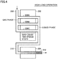
- Fig. 4 shows a state of refrigerant in a condenser during high-load operation.
- Fig. 5 shows a state of refrigerant in the condenser during low-load operation.
- the condenser shown in Figs. 4 and 5 corresponds to outdoor heat exchanger 30 shown in Fig. 1 , but includes neither pipes 113 to 115 nor switching device 36 shown in Fig. 1 .
- the condenser shown herein correspond to a conventional configuration.
- this condenser includes a main heat exchanger 202 and a subcooling heat exchanger 204 similarly to outdoor heat exchanger 30.
- Each heat exchanger has the same path number as that of outdoor heat exchanger 3: the path number of main heat exchanger 202 is three, and the path number of subcooling heat exchanger 204 is one.
- the refrigerant In pipe 206 before refrigerant flows into main heat exchanger 202, the refrigerant is in gas phase (superheated vapor).
- the refrigerant flows into heat transfer tubes 208A to 208C in main heat exchanger 202, the refrigerant exchanges heat with (radiates heat to) outdoor air to have a decreased degree of dryness. Consequently, the refrigerant enters the gas-liquid two-phase state and enters the liquid state in the vicinity of the output end of main heat exchanger 32.
- the refrigerant (liquid refrigerant) which has flowed through main heat exchanger 202 is delivered through pipe 210 to subcooling heat exchanger 204.
- the refrigerant flows into subcooling heat exchanger 204, the refrigerant exchanges heat with (radiates heat to) outdoor air to be supercooled state, thereby being output to pipe 212.
- the refrigerant in the low-load operation in which compressor 10 has a smaller number of rotations than in high-load operation, the refrigerant has a smaller mass flow rate than during high-load operation, and accordingly, the refrigerant starts condensing on the more upstream side than in high-load operation. In low-load operation, thus, the refrigerant changes to the liquid phase in main heat exchanger 202 earlier than in the high-load operation shown in Fig. 4 .
- the refrigerant changes its phase in the condenser differently between in high-load operation and in low-load operation: during low-load operation, a more amount of the refrigerant turns into liquid refrigerant to be accumulated in the condenser than during the high-load operation. Consequently, the amount of refrigerant required for the refrigerant circuit in low-load operation is more than the amount of refrigerant required in high-load operation.
- the amount of refrigerant sealed in the refrigerant circuit affects the performance of the refrigeration cycle.
- Fig. 6 is a p-h diagram of the refrigeration cycle.
- the vertical axis represents a pressure p (MPa)
- the horizontal axis represents a specific enthalpy h (kJ/kg).
- the solid line indicated by four straight lines represents a state at a time when the refrigeration cycle operates with a certain amount of refrigerant sealed therein.
- the curved line is a saturated liquid line (saturated vapor line) of the refrigerant.
- a cooling capacity Qe of the refrigeration cycle can be represented by the following equation.
- Qe Gr ⁇ ⁇ he
- Gr represents a circulation flow rate (kg/s) of refrigerant
- ⁇ he represents an enthalpy difference in the evaporator (indoor heat exchanger 50 during cooling operation).
- a heating capacity Qc of the refrigeration cycle can be represented by the following equation.
- Qc Gr ⁇ ⁇ hc
- ⁇ hc represents an enthalpy difference in the condenser during heating operation (indoor heat exchanger 50 during heating operation).
- Power Wcomp of the compressor is represented by the following equation.
- Wcomp Gr ⁇ ⁇ hcomp
- ⁇ hcomp represents an enthalpy difference in the compressor.
- an amount of heat exchange Q between refrigerant and air in the condenser is represented by the following equation.
- Q A ⁇ K ⁇ Tc ⁇ Ta
- A represents a surface area outside the pipe of the condenser
- Tc represents a condensation temperature
- Ta represents a temperature of sucked air of the condenser (outdoor air temperature).
- the performance of the refrigeration cycle decreases in both of the case where the amount of refrigerant is excessively small and the case where the amount of refrigerant is excessively large as described above, and accordingly, there is such an amount of refrigerant that maximizes the performance of the refrigeration cycle.
- Fig. 8 shows a qualitative relation between an amount of refrigerant and COP.
- a line L1 indicates the relation between the amount of refrigerant and COP on a high-load condition on which the refrigeration cycle operates at high load.
- a line L2 indicates the relation between an amount of refrigerant and COP on a low-load condition on which the refrigeration cycle operates at low load. Since an amount of refrigerant required for the refrigerant circuit in low-load operation is larger than the amount of refrigerant required in high-load operation as described with reference to Figs. 4 and 5 , an amount of refrigerant M2 that maximizes the performance of the refrigeration cycle on the low-load condition is larger than an amount of refrigerant M1 that maximizes the performance of the refrigeration cycle on the high-load condition.
- Air conditioner 1 to which the refrigeration cycle apparatus is applied performs the high-load operation or the low-load operation depending on room temperature as in Embodiment 1, and is thus required to achieve high performance for both of the operation states.
- the amount of refrigerant that maximizes the performance of the refrigeration cycle apparatus differs between in high-load operation and in low-load operation. For this reason, when the amount of refrigerant is set to M1 in accordance with the high-load operation, the COP is maximized in high-load operation, but the amount of refrigerant becomes insufficient in low-load operation. This leads to decreased COP in low-load operation.
- a bypass circuit for causing refrigerant to make a detour from subcooling heat exchanger 34 to pipe 66 on the exit side of outdoor heat exchanger 30 is provided.
- This bypass circuit is used to cause refrigerant (liquid refrigerant) accumulated in subcooling heat exchanger 34 to make a detour to the exit side of subcooling heat exchanger 34 during low-load operation.
- the amount of refrigerant required for the refrigerant circuit in low-load operation can be decreased, thus shifting the relation between the amount of refrigerant and COP on the low-load condition from line L2 to line L3 ( Fig. 8 ).
- This can decrease a gap between amount of refrigerant M1 that maximizes the performance of the refrigeration cycle on the high-load condition and the amount of refrigerant that maximizes the performance of the refrigeration cycle on the low-load condition, thus achieving high performance in both of the high-load operation and the low-load operation.
- Fig. 9 shows a detailed configuration of outdoor heat exchanger 30 shown in Fig. 1 .
- main heat exchanger 32 and subcooling heat exchanger 34 each include heat transfer tubes 120.
- Main heat exchanger 32 includes three paths connected in parallel with each other, and each path is composed of heat transfer tubes 120 (six heat transfer tubes in this example) connected in series.
- the path number of subcooling heat exchanger 34 is one, and subcooling heat exchanger 34 is also composed of heat transfer tubes 120 (six heat transfer tubes in this example).
- Switching device 36 includes solenoid valves 130 and 132. Solenoid valve 130 is provided between pipe 113 and pipe 115. Solenoid valve 132 is provided between pipe 113 and pipe 114. Switching device 36 can switch between two flow paths from some midpoint of subcooling heat exchanger 34. Specifically, one is a flow path in which refrigerant again flows into the remaining heat transfer tubes of subcooling heat exchanger 34 through solenoid valve 130 (which is referred to as flow path A), and the other is a flow path in which refrigerant flows to pipe 66 through solenoid valve 132 (which is referred to as flow path B).
- solenoid valves 130 and 132 When solenoid valves 130 and 132 are respectively opened and closed, flow path A is formed, and refrigerant flows through all the heat transfer tubes provided in subcooling heat exchanger 34. On the other hand, when solenoid valves 130 and 132 are respectively closed and opened, flow path B is formed, and refrigerant flows to pipe 66 through the bypass circuit. Solenoid valves 130 and 132 are controlled to be opened and closed by controller 100 ( Fig. 1 ) depending on the load of air conditioner 1.
- Fig. 10 is a flowchart showing a procedure of controlling switching device 36 by controller 100 shown in Fig. 1 . A series of processes shown in this flowchart are repeatedly performed per predetermined period of time during the cooling operation of air conditioner 1.
- controller 100 determines whether the load of air conditioner 1 is high or low through the processes of steps S10 to S30, and in accordance with a result of the determination, controls solenoid valves 130 and 132 of switching device 36 to be opened and closed.
- controller 100 obtains, from temperature sensors 82 and 84 ( Fig. 1 ), condensation temperature Tc1 and outdoor air temperature Tal, respectively (step S10). Controller 100 then calculates a temperature difference ⁇ T1 between condensation temperature Tc1 and outdoor air temperature Ta1 (step S20). Controller 100 then determines whether the calculated temperature difference ⁇ T1 is greater than a threshold K1 (step S30). Threshold K1 is a value against which whether the load of air conditioner 1 is high or low is determined. Threshold K1 is obtained by, for example, prior evaluation or simulation of air conditioner 1 and is stored in the ROM of controller 100.
- Embodiment 1 whether the load of air conditioner 1 is high or low is determined based on temperature difference ⁇ T1 between condensation temperature Tc1 and outdoor air temperature Tal, as described above.
- air conditioner 1 has a high load, amount of heat exchange Q between refrigerant and air is also large in the condenser (outdoor heat exchanger 30 during cooling operation), and accordingly, temperature difference ⁇ T1 between condensation temperature Tc1 and outdoor air temperature Ta1 increases, as can be seen from Equation (6) above.
- the load of air conditioner 1 can be determined to be high when temperature difference ⁇ T1 is large, and the load of air conditioner 1 can be determined to be low when temperature difference ⁇ T1 is small.
- controller 100 determines that air conditioner 1 is operated at high load (step S40). Controller 100 then controls solenoid valves 130 and 132 of switching device 36 respectively to be opened and closed (step S50). Consequently, the refrigerant flows through all the heat transfer tubes in subcooling heat exchanger 34 without being bypassed by the bypass circuit.
- controller 100 determines that air conditioner 1 is operated at low load (step S60). Controller 100 then controls solenoid valves 130 and 132 of switching device 36 respectively to be closed and opened (step S70). Consequently, the refrigerant flows to pipe 66 from subcooling heat exchanger 34 through the bypass circuit.
- Embodiment 1 in which the refrigerant (liquid refrigerant) flows through the bypass circuit to the exit side of outdoor heat exchanger 30 from subcooling heat exchanger 34 during low-load operation, can reliably restrain accumulation of refrigerant in outdoor heat exchanger 30 during low-load operation. This can reduce the amount of refrigerant required in low-load operation, thus reducing a gap between the amount of refrigerant required in high-load operation and the amount of refrigerant required in low-load operation. Embodiment 1 can thus achieve high performance in both of the high-load operation and the low-load operation.
- Embodiment 1 in which outdoor heat exchanger 30 is composed of main heat exchanger 32 and subcooling heat exchanger 34, can thus achieve high performance regardless of the load of outdoor heat exchanger 30 by further including a bypass circuit while achieving improvements in the performance (improvements in surface coefficient of heat transfer) of outdoor heat exchanger 30 owing to the above configuration.
- Solenoid valves 130 and 132 may be replaced with a three-way valve.
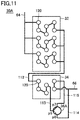
- Fig. 11 shows a configuration of an outdoor heat exchanger in Modification 1.
- Air conditioner 1 according to Modification 1 includes an outdoor heat exchanger 30A in place of outdoor heat exchanger 30 in Embodiment 1.
- outdoor heat exchanger 30A includes, in outdoor heat exchanger 30 shown in Fig. 9 , a three-way valve 36A in place of switching device 36.
- Three-way valve 36A has ports p5 to p7.
- Pipes 113 to 11 are respectively connected to ports p5 to p7.
- Fig. 12 is a flowchart showing a procedure of controlling three-way valve 36A by controller 100. This flowchart corresponds to Fig. 10 described in Embodiment 1, and a series of processes shown in this flowchart are repeatedly performed per predetermined period of time during the cooling operation of air conditioner 1.
- steps S110 to S140 and S160 shown in this flowchart are respectively identical to the processes of steps S10 to S40 and S60 shown in Fig. 10 .
- This flowchart includes steps S150 and S170 respectively in place of steps S50 and S70 shown in the flowchart of Fig. 10 .
- controller 100 controls three-way valve 36A such that port p5 and port p7 of three-way valve 36A are communicatively connected with each other (step S150).
- step S140 when air conditioner 1 is operated at high load, refrigerant flows through all the heat transfer tubes in subcooling heat exchanger 34 without being bypassed by the bypass circuit.
- controller 100 controls three-way valve 36A such that port p5 and port p6 of three-way valve 36A are communicatively connected with each other (step S170).
- step S170 refrigerant flows through the bypass circuit from subcooling heat exchanger 34 to pipe 66.
- Modification 1 can also achieve effects similar to those of Embodiment 1.
- a capillary tube is provided in a bypass circuit.
- Providing the capillary tube can decrease a pressure on the exit side of outdoor heat exchanger 30, that is, the exit side of subcooling heat exchanger 34, when refrigerant flows through the bypass circuit to pipe 66.
- Pressure can be decreased by the capillary tube such that the pressure on the exit side of subcooling heat exchanger 34 can be lower than a saturation pressure of refrigerant at outdoor air temperature, to thereby suck refrigerant present from solenoid valve 130 to the exit side of subcooling heat exchanger 34 into pipe 66. This can reliably restrain accumulation of refrigerant in subcooling heat exchanger 34.
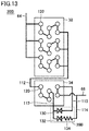
- Fig. 13 shows a configuration of an outdoor heat exchanger in Modification 2.
- Air conditioner 1 according to Modification 2 includes an outdoor heat exchanger 30B in place of outdoor heat exchanger 30 in Embodiment 1.
- outdoor heat exchanger 30B includes, in outdoor heat exchanger 30 shown in Fig. 9 , a switching device 36B in place of switching device 36.
- Switching device 36B further includes a capillary tube 134 in switching device 36.
- Capillary tube 134 is connected between solenoid valve 132 and pipe 114.
- Capillary tube 134 is, for example, a capillary tube made of copper.
- the pressure of the refrigerant decreases.
- capillary tube 134 is designed such that during low-load operation, the pressure on the output side of capillary tube 134 is sufficiently lower than the saturation pressure of the refrigerant at outdoor air temperature even when outdoor air temperature varies within the range of specifications.
- Modification 2 including capillary tube 134 can reliably restrain accumulation of refrigerant in subcooling heat exchanger 34 when refrigerant flows through the bypass circuit to pipe 66.
- capillary tube 134 may be provided on the exit side of port p6 of three-way valve 36A ( Fig. 11 ) in Modification 1 described above.
- Embodiment 2 a mechanical pressure on-off valve is provided in the bypass circuit in place of solenoid valves 130 and 132 and three-way valve 36A described above. This eliminates the need for electric equipment for activating a valve, leading to a reduced device cost.
- Air conditioner 1 in Embodiment 2 includes, in the configuration of the air conditioner shown in Fig. 1 , an outdoor heat exchanger 30C in place of outdoor heat exchanger 30.
- Fig. 14 shows a configuration of outdoor heat exchanger 30C in Embodiment 2.
- outdoor heat exchanger 30C includes main heat exchanger 32, a subcooling heat exchanger 34A, and a switching device 36C.
- Subcooling heat exchanger 34A has a branch portion B, and pipe 113 is connected to branch portion B.
- Switching device 36C includes a pressure on-off valve 136 and a check valve 138.
- Pressure on-off valve 136 is provided between pipe 113 and pipe 140.
- Check valve 138 is provided between pipe 140 and pipe 114.
- Pressure on-off valve 136 needs no electric power for opening and closing operations.
- Pressure on-off valve 136 is configured to be closed when the pressure of pipe 113 exceeds a prescribed pressure and to be opened when the pressure of pipe 113 is lower than the prescribed pressure.
- a specific configuration of pressure on-off valve 136 will be described below.
- Check valve 138 prevents refrigerant from flowing from pipe 114 through switching device 36C to pipe 113.
- Check valve 138 serves to prevent refrigerant from flowing from pipe 66 through switching device 36C to branch portion B of subcooling heat exchanger 34A when outdoor heat exchanger 30C operates as an evaporator (during heating operation).
- Figs. 15 and 16 show an example configuration of pressure on-off valve 136.
- Fig. 15 shows the state of pressure on-off valve 136 opened
- Fig. 16 shows the state of pressure on-off valve 136 closed.
- pressure on-off valve 136 includes a diaphragm 152, a noncondensable gas 154, a temperature sensitive cylinder 156, a valve body 158, a valve seat 160, and a spring 162.
- Valve body 158 and valve seat 160 are hollow tubular members and are configured such that valve body 158 is movable vertically relative to valve seat 160 with the inner circumference surface of valve body 158 and the outer circumference surface of valve seat 160 contacting each other.
- the upper portion of valve body 158 is connected to diaphragm 152.
- Valve seat 160 is fixed to the side wall of pressure on-off valve 136, and the interior of valve body 158 is in communication with pipe 140. Also, valve body 158 and valve seat 160 are connected by spring 162.
- Diaphragm 152 moves upward when the pressure of pipe 113 increases and moves downward when the pressure of pipe 113 decreases.
- valve body 158 moves upward together with diaphragm 152 relative to valve seat 160.
- valve body 158 moves downward together with diaphragm 152 relative to valve seat 160.
- valve body 158 and valve seat 160 is provided with an opening.
- the opening of valve body 158 and the opening of valve seat 160 are formed so as to overlap each other when valve body 158 moves downward relative to valve seat 160.
- the openings are formed so as not to overlap each other when valve body 158 moves upward relative to valve seat 160.
- valve body 158 moves downward as diaphragm 152 moves downward, so that pipe 140 is in communication with pipe 113 through the openings of valve body 158 and valve seat 160.
- the pressure in outdoor heat exchanger 30C that is, the pressure of pipe 113 is relatively low, thereby opening pressure on-off valve 136 ( Fig. 16 ).
- valve body 158 moves upward as diaphragm 152 moves upward, and the openings thereof deviate from each other. As a result, pipe 113 and pipe 140 are not in communication with each other.
- the pressure of pipe 113 is relatively high, thereby closing pressure on-off valve 136 ( Fig. 15 ).
- Pressure on-off valve 136 includes a temperature sensitive cylinder 156. Temperature sensitive cylinder 156 is exposed to outdoor air, and the pressure of noncondensable gas 154 increases as outdoor air temperature is higher. Providing such a temperature sensitive cylinder 156 can prevent the pressure of refrigerant from increasing due to a high outdoor air temperature to close pressure on-off valve 136 irrespective of operation load. In other words, providing temperature sensitive cylinder 156 can reduce dependence of the opening and closing operations of pressure on-off valve 136 on outside air temperature, thus activating pressure on-off valve 136 in accordance with operation load.
- temperature sensitive cylinder 156 described above is not an essential component. As shown in Fig. 17 , a pressure on-off valve 136A without temperature sensitive cylinder 156 may be adopted.
- Embodiment 2 including mechanical pressure on-off valve 136 requires no electric equipment for operating a vale, leading to reduced device cost.
- the path number of subcooling heat exchanger 34 is made smaller than the path number of main heat exchanger 32 to increase a flow velocity in subcooling heat exchanger 34, leading to enhanced performance (surface coefficient of heat transfer) of outdoor heat exchanger 30.
- a tube diameter of the heat transfer tube of subcooling heat exchanger 34 is made smaller than the tube diameter of the heat transfer tube of main heat exchanger 32 to increase the flow velocity in subcooling heat exchanger 34, leading to enhanced performance (surface coefficient of heat transfer) of outdoor heat exchanger 30.
- a bypass circuit is formed from subcooling heat exchanger 34, and refrigerant (liquid refrigerant) flows through the bypass circuit from subcooling heat exchanger 34 to the exit side of outdoor heat exchanger 30 during low-load operation.
- Air conditioner 1 in Embodiment 3 includes, in the configuration of the air conditioner shown in Fig. 1 , an outdoor heat exchanger 30D in place of outdoor heat exchanger 30.
- Fig. 18 shows a configuration of an outdoor heat exchanger 30D in Embodiment 3.
- outdoor heat exchanger 30D includes a main heat exchanger 32A, subcooling heat exchanger 34, and switching device 36.
- Subcooling heat exchanger 34 and switching device 36 are as described with reference to Fig. 9 .
- Main heat exchanger 32A includes a plurality of heat transfer tubes 120A (six heat transfer tubes in this example) connected in series.
- Heat transfer tube 120A has a tube diameter larger than the tube diameter of heat transfer tube 120 in subcooling heat exchanger 34.
- heat transfer tube 120 of subcooling heat exchanger 34 has a tube diameter smaller than the tube diameter of heat transfer tube 120A of main heat exchanger 32A. This increases the flow velocity of liquid refrigerant flowing through subcooling heat exchanger 34 with respect to main heat exchanger 32A, to thereby enhance the performance (surface coefficient of heat transfer) of outdoor heat exchanger 30D.
- outdoor heat exchanger 30D includes switching device 36 in Embodiment 3, as in the modifications and Embodiment 2 described above, three-way valve 36A may be adopted in place of switching device 36, switching device 36B including capillary tube 134 may be adopted, or switching device 36C including pressure on-off valve 136 and check valve 138 may be adopted in Embodiment 3.
- Embodiment 3 can also achieve effects similar to those of the embodiments and the modifications described above.
- Indoor heat exchanger 50 functioning as a condenser during heating operation may also be composed of a main heat exchanger and a subcooling heat exchanger, and may be configured such that refrigerant can flow through a bypass circuit from the subcooling heat exchanger of indoor heat exchanger 50. Consequently, an air conditioner is achieved that can achieve high performance in both of the high-load operation and the low-load operation also during heating operation.
- FIG. 19 is an overall configuration diagram of an air conditioner to which a refrigeration cycle apparatus according to Embodiment 4 is applied.
- air conditioner 1A includes outdoor unit 2 and an indoor unit 3A.
- Indoor unit 3A includes an indoor heat exchanger 50A, fan 58, and temperature sensors 86 and 88.
- Indoor heat exchanger 50A includes main heat exchanger 52, subcooling heat exchanger 54, and switching device 56.
- Main heat exchanger 52 and subcooling heat exchanger 54 are connected in series. Main heat exchanger 52 and subcooling heat exchanger 54 are disposed to be respectively connected to pipes 70 and 68.
- the configurations of main heat exchanger 52 and subcooling heat exchanger 54 are respectively similar to the configurations of main heat exchanger 32 and subcooling heat exchanger 34 of outdoor heat exchanger 30.
- Embodiment 4 including main heat exchanger 52 and subcooling heat exchanger 54 has enhanced performance (surface coefficient of heat transfer) of indoor heat exchanger 50A during heating operation.
- switching device 56 is also similar to the configuration of switching device 36 of outdoor heat exchanger 30. Specifically, switching device 56 is configured to switch between flowing refrigerant, which is output from subcooling heat exchanger 54 to switching device 56 during heating operation, to pipe 68 and returning the refrigerant to subcooling heat exchanger 54. Switching device 56 is controlled in accordance with a control signal Op2 from controller 100, and during heating operation, causes refrigerant to make a detour from subcooling heat exchanger 54 to pipe 68 when air conditioner 1A has a low load.
- a control signal Op2 from controller 100
- Temperature sensor 86 detects a condensation temperature Tc2 of refrigerant in indoor heat exchanger 50A and outputs a detected value to controller 100.
- Temperature sensor 88 detects a temperature Ta2 of the air supplied to indoor heat exchanger 50A by fan 58 and outputs a detected value to controller 100.
- an air conditioner that can achieve high performance in both of the high-load operation and the low-load operation is achieved also when air conditioner 1A performs the heating operation.
- a three-way valve may be adopted in place of switching device 56 as in the modifications of Embodiment 1 and Embodiments 2 and 3, and may include a switching device including a capillary tube.
- a switching device including a pressure on-off valve and a check valve may be adopted, or a heat exchanger having a configuration similar to that of main heat exchanger 32A ( Fig. 18 ) in place of main heat exchanger 52 may be adopted.
Landscapes
- Engineering & Computer Science (AREA)
- General Engineering & Computer Science (AREA)
- Mechanical Engineering (AREA)
- Physics & Mathematics (AREA)
- Thermal Sciences (AREA)
- Compression-Type Refrigeration Machines With Reversible Cycles (AREA)
Abstract
Description
- The present disclosure relates to a refrigeration cycle apparatus.
- Japanese Patent Laying-Open No.
2017-219216 - Each heat exchange region includes a plurality of heat transfer tubes provided in parallel. The sub-heat exchange region is configured to have the number of parallel heat transfer tubes (hereinafter also referred to as the "path number") lower than that of the main heat exchange region. This increases a surface coefficient of heat transfer in the heat exchanger to improve the performance of the heat exchanger (see PTL 1).
- PTL 1: Japanese Patent Laying-Open No.
2017-219216 - The capacity of a refrigeration cycle can be adjusted by changing the number of rotations (operating frequency) of a compressor to change a circulation amount of refrigerant. For example, in an air conditioner using a refrigeration cycle, at high room temperature during cooling operation, the number of rotations of a compressor is increased to increase a circulation amount of refrigerant, thereby enhancing cooling capacity (high-load operation). Then, as room temperature decreases, the number of rotations of the compressor is decreased to reduce the circulation amount of refrigerant, thereby restraining the cooling capacity (low-load operation).
- In the low-load operation with a small number of rotations of the compressor, a mass flow rate of refrigerant is low, and accordingly, refrigerant starts condensing on a more upstream side than in the high-load operation (e.g., rated operation) in the condenser. For example, in the heat exchanger including the main heat exchange region (hereinafter also referred to as a "main heat exchanger") and the sub-heat exchange region (hereinafter also referred to as a "sub-cooling heat exchanger") as in the heat exchanger disclosed in
PTL 1, refrigerant may turn into liquid refrigerant at some midpoint of the main heat exchanger during low-load operation. Since refrigerant (liquid refrigerant) is accumulated in the condenser during low-load operation as described above, an amount of refrigerant required in low-load operation (a total amount of refrigerant sealed in a refrigerant circuit) is larger than an amount of refrigerant required in high-load operation. - In the refrigeration cycle, the amount of refrigerant in the refrigerant circuit affects the performance of the refrigeration cycle. As described below in detail, in a qualitative manner, if the amount of refrigerant is smaller than a proper amount, the degree of supercooling of refrigerant will decrease. As a result, an enthalpy difference decreases in the heat exchanger, leading to decreased performance of the refrigeration cycle. On the other hand, if the amount of refrigerant is larger than the proper amount, a large amount of refrigerant is accumulated in the condenser, leading to a decreased region in gas-liquid two-phase state. As a result, an average surface coefficient of heat transfer in the tube of the condenser decreases, leading to a decreased thermal transmittance. Since condensation temperature rises as the thermal transmittance decreases, a workload of the compressor increases, resulting in decreased performance of the refrigeration cycle. As described above, the performance of the refrigeration cycle decreases if the amount of refrigerant is less or more than the proper amount, and there is such an amount of refrigerant that maximizes the performance of the refrigeration cycle.
- The refrigeration cycle apparatus is required to have high performance in high-load operation and also in low-load operation. For example, the air conditioner using a refrigeration cycle enters the high-load operation or the low-load operation depending on room temperature as described above, and is thus required to achieve high performance in both of these operation states. Between in the high-load operation and in the low-load operation, however, a required amount of refrigerant differs, and such an amount of refrigerant that maximizes the performance of the refrigeration cycle also differs. For example, when an amount of refrigerant is set in accordance with the high-load operation (e.g., rated operation), thus, the amount of refrigerant becomes insufficient for the low-load operation, which may decrease the performance in low-load operation.
- The present disclosure has been made to solve the above problem, and an object of the present disclosure is to provide a refrigeration cycle apparatus that can achieve high performance in both of the high-load operation and the low-load operation.
- A refrigeration cycle apparatus of the present disclosure includes a refrigerant circuit in which a compressor, a condenser, an expansion valve, and an evaporator are connected in a loop by refrigerant pipes. The condenser includes a main heat exchanger, a subcooling heat exchanger, and a bypass circuit. The subcooling heat exchanger is configured to allow refrigerant from the main heat exchanger to flow through the subcooling heat exchanger. The bypass circuit is configured to cause the refrigerant to make a detour from the subcooling heat exchanger to an exit side of the condenser.
- Refrigerant in liquid phase (liquid refrigerant) flows through the subcooling heat exchanger through which the refrigerant from the main heat exchanger flows. This refrigeration cycle apparatus, in which the bypass circuit causes the refrigerant (liquid refrigerant) to make a detour from the subcooling heat exchanger to the exit side of the condenser, can reliably restrain accumulation of refrigerant in the condenser.
- Thus, this refrigeration cycle apparatus can bring the bypass circuit to become conductive during low-load operation to have a smaller amount of refrigerant required in low-load operation than in the case where no bypass circuit is provided (a case where liquid refrigerant is accumulated in the subcooling heat exchanger). This can reduce a gap between the amount of refrigerant required in high-load operation and the amount of refrigerant required in low-load operation, thus achieving high performance in both of the high-load operation and the low-load operation.
- The refrigeration cycle apparatus of the present disclosure can achieve high performance in both of the high-load operation and the low-load operation.
-
-
Fig. 1 is an overall configuration diagram of an air conditioner to which a refrigeration cycle apparatus according toEmbodiment 1 of the present disclosure is applied. -
Fig. 2 shows a flow of refrigerant during cooling operation. -
Fig. 3 shows a flow of refrigerant during heating operation. -
Fig. 4 shows a state of refrigerant in a condenser during high-load operation. -
Fig. 5 shows a state of refrigerant in the condenser during low-load operation. -
Fig. 6 is a p-h diagram of a refrigeration cycle. -
Fig. 7 is a p-h diagram of the refrigeration cycle. -
Fig. 8 shows a qualitative relation between an amount of refrigerant and COP. -
Fig. 9 shows a detailed configuration of an outdoor heat exchanger shown inFig. 1 . -
Fig. 10 is a flowchart showing a procedure of controlling a switching device by a controller shown inFig. 1 . -
Fig. 11 shows a configuration of an outdoor heat exchanger inModification 1. -
Fig. 12 is a flowchart showing a procedure of controlling a three-way valve by the controller. -
Fig. 13 shows a configuration of an outdoor heat exchanger inModification 2. -
Fig. 14 shows a configuration of an outdoor heat exchanger in Embodiment 2. -
Fig. 15 shows a state of a pressure on-off valve closed. -
Fig. 16 shows a state of the pressure on-off valve opened. -
Fig. 17 shows another configuration example of the pressure on-off valve. -
Fig. 18 shows a configuration of an outdoor heat exchanger in Embodiment 3. -
Fig. 19 is an overall configuration diagram of an air conditioner to which a refrigeration cycle apparatus according to Embodiment 4 is applied. - Embodiments of the present invention will be described below in detail with reference to the drawings. The same or corresponding parts in the drawings are designated by the same references, and description thereof will not be repeated.
-
Fig. 1 is an overall configuration diagram of an air conditioner to which a refrigeration cycle apparatus according toEmbodiment 1 of the present disclosure is applied. Referring toFig. 1 , anair conditioner 1 includes anoutdoor unit 2 and anindoor unit 3.Outdoor unit 2 is placed outdoors, andindoor unit 3 is placed in a space to be air-conditioned (indoors). -
Outdoor unit 2 includes acompressor 10, a four-way valve 20, anoutdoor heat exchanger 30, afan 38, and anexpansion valve 40.Outdoor unit 2 additionally includespipes temperature sensors controller 100.Indoor unit 3 includes anindoor heat exchanger 50 and afan 58.Indoor unit 3 is connected tooutdoor unit 2 throughpipes Compressor 10, four-way valve 20,outdoor heat exchanger 30,expansion valve 40,indoor heat exchanger 50, andpipes -
Pipe 62 connects a discharge port ofcompressor 10 with a port p1 of four-way valve 20.Pipe 64 connects a port p2 of four-way valve 20 withoutdoor heat exchanger 30.Pipe 66 connectsoutdoor heat exchanger 30 withexpansion valve 40.Pipe 68 connectsexpansion valve 40 withindoor heat exchanger 50.Pipe 70 connectsindoor heat exchanger 50 with a port p3 of four-way valve 20.Pipe 72 connects a port p4 of four-way valve 20 with a suction port ofcompressor 10. -
Compressor 10 compresses refrigerant sucked frompipe 72 and outputs the refrigerant topipe 62.Compressor 10 is configured to adjust the number of rotations (operating frequency) in accordance with a control signal fromcontroller 100. Adjusting the number of rotations ofcompressor 10 can adjust a circulation amount of refrigerant of the refrigerant circuit, to thereby adjust the capacity ofair conditioner 1.Compressor 10 can be of various types, and is of, for example, rotary type, reciprocation type, scroll type, or screw type. - Four-
way valve 20 is switched between a first state (cooling operation) and a second state (heating operation) in accordance with a control signal fromcontroller 100. In the first state, port p1 is communicatively connected with port p2, and port p3 is communicatively connected with port p4. In the first state, thus,pipe 62 is connected withpipe 64, andpipe 70 is connected withpipe 72. In the second state, port p1 is communicatively connected with port p3, and port p2 is communicatively connected with port p4. In the second state, thus,pipe 62 is connected withpipe 70, andpipe 64 is connected withpipe 72. - During cooling operation,
outdoor heat exchanger 30 functions as a condenser, and condenses refrigerant output fromcompressor 10 through four-way valve 20 topipe 64 and outputs the refrigerant topipe 66.Outdoor heat exchanger 30 is configured to allow high-temperature, high-pressure superheated vapor (refrigerant) output fromcompressor 10 to exchange heat with (radiate heat to) outdoor air. Through this heat exchange, refrigerant is condensed to turn into a liquid phase. On the other hand, during heating operation,outdoor heat exchanger 30 functions as an evaporator, and evaporates refrigerant output fromexpansion valve 40 topipe 66 and outputs the refrigerant topipe 64. -
Outdoor heat exchanger 30 includes amain heat exchanger 32, asubcooling heat exchanger 34,pipes 112 to 115, and aswitching device 36.Main heat exchanger 32 andsubcooling heat exchanger 34 are connected in series bypipe 112.Main heat exchanger 32 andsubcooling heat exchanger 34 are disposed respectively to be connected topipes -
Main heat exchanger 32 includes a plurality of paths connected in parallel with each other and is configured such that the path number ofmain heat exchanger 32 is larger than the path number ofsubcooling heat exchanger 34. In other words,subcooling heat exchanger 34 is configured to have a path number smaller than the path number ofmain heat exchanger 32. In this example, the path number ofmain heat exchanger 32 is three, and the path number ofsubcooling heat exchanger 34 is one. - In
air conditioner 1, the performance ofoutdoor heat exchanger 30 is enhanced by configuringoutdoor heat exchanger 30 such that the path number ofsubcooling heat exchanger 34 is smaller than the path number ofmain heat exchanger 32. Specifically, in the cooling operation in whichoutdoor heat exchanger 30 functions as a condenser, refrigerant changes from the gas phase to the liquid phase withinoutdoor heat exchanger 30. Since refrigerant in the liquid phase (liquid refrigerant) has a surface coefficient of heat transfer lower than that of refrigerant in the gas-liquid two-phase state when changing from the gas phase to the liquid phase, in the condenser, the surface coefficient of heat transfer of the condenser can be increased by increasing a flow velocity of the liquid refrigerant. Inair conditioner 1, thus, the flow velocity of liquid refrigerant flowing throughsubcooling heat exchanger 34 can be increased by causingsubcooling heat exchanger 34, through which refrigerant that has changed to the liquid phase bymain heat exchanger 32, to have a path number smaller than the path number ofmain heat exchanger 32. Consequently, the performance (surface coefficient of heat transfer) ofoutdoor heat exchanger 30 is increased. - The path numbers of
main heat exchanger 32 andsubcooling heat exchanger 34 are not limited to the numbers described above. The path number ofmain heat exchanger 32 may be two or four or more, and the path number ofsubcooling heat exchanger 34 may be more than one. -
Pipe 113 connectssubcooling heat exchanger 34 with switchingdevice 36.Pipe 114 connects switchingdevice 36 withpipe 66.Pipe 115 connects switchingdevice 36 withsubcooling heat exchanger 34.Pipes subcooling heat exchanger 34 topipe 66.Pipe 115 forms a return path for returning refrigerant tosubcooling heat exchanger 34. -
Switching device 36 is configured to switch between outputting refrigerant, which is output fromsubcooling heat exchanger 34 topipe 113 during cooling operation, topipe 114 to flow the refrigerant topipe 66 and outputting the refrigerant topipe 115 to return the refrigerant tosubcooling heat exchanger 34.Switching device 36 is controlled by a control signal Op1 from the controller to cause refrigerant to flow frompipe 113 topipe 115 whenair conditioner 1 has a high load and cause refrigerant to flow frompipe 113 topipe 114 whenair conditioner 1 has a low load. During heating operation, switchingdevice 36 operates to cause refrigerant to flow frompipe 115 topipe 113. The configurations ofsubcooling heat exchanger 34 and switchingdevice 36 will be described below in detail. -
Fan 38 is placed side by side withoutdoor heat exchanger 30 and blows air tooutdoor heat exchanger 30. During cooling operation,expansion valve 40 decompresses refrigerant output fromoutdoor heat exchanger 30 topipe 66 and outputs the refrigerant topipe 68.Expansion valve 40 is, for example, an electronic expansion valve and has a degree of opening adjusted in accordance with a control signal fromcontroller 100. When the degree of opening ofexpansion valve 40 is changed so as to be closed, the refrigerant pressure on the exit side ofexpansion valve 40 decreases, and the degree of dryness of refrigerant increases. When the degree of opening ofexpansion valve 40 is changed so as to be opened, the refrigerant pressure on the exit side ofexpansion valve 40 increases, and the degree of dryness of refrigerant decreases. -
Temperature sensor 82 detects a condensation temperature Tc1 of refrigerant inoutdoor heat exchanger 30 and outputs a detected value tocontroller 100.Temperature sensor 84 detects an outdoor air temperature Ta1 at a place at which outdoor unit 2 (outdoor heat exchanger 30) is placed and outputs a detected value tocontroller 100. -
Indoor heat exchanger 50 functions as an evaporator during cooling operation, and evaporates refrigerant output fromexpansion valve 40 topipe 68 and outputs the refrigerant topipe 70.Indoor heat exchanger 50 is configured to allow refrigerant which has been decompressed byexpansion valve 40 to exchange heat with (absorb heat of) indoor air. Through this heat exchange, refrigerant evaporates to turn into superheated vapor. On the other hand, during heating operation,indoor heat exchanger 50 functions as a condenser, and condenses refrigerant output fromcompressor 10 through four-way valve 20 topipe 70 and outputs the refrigerant topipe 68.Fan 58 is provided side by side withindoor heat exchanger 50 and blows air toindoor heat exchanger 50. -
Controller 100 includes a central processing unit (CPU), memories (a read only memory (ROM) and a random access memory (RAM)), an I/O buffer for inputting/outputting various signals, and the like (all of which are not shown). The CPU loads the programs stored in the ROM to the RAM or the like and executes the program. The program stored in the ROM is a program in which the procedure ofcontroller 100 is described.Controller 100 controls each equipment inair conditioner 1 in accordance with these programs. This control may be processed by software, as well as dedicated hardware (electronic circuit). -
Fig. 2 shows a flow of refrigerant during cooling operation. Referring toFig. 2 , during cooling operation, refrigerant which has turned into high-temperature, high-pressure vapor bycompressor 10, is supplied through four-way valve 20 tooutdoor heat exchanger 30, and then exchanges heat with (radiates heat to) outdoor air inoutdoor heat exchanger 30 to be condensed, thereby turning into high-pressure liquid refrigerant. - Subsequently, the refrigerant is decompressed in
expansion valve 40 and is supplied toindoor heat exchanger 50. The refrigerant then exchanges heat with (absorbs heat of) indoor air inindoor heat exchanger 50 to evaporate, thereby turning into low-pressure gas refrigerant. The refrigerant then flows through four-way valve 20 and is sucked again bycompressor 10. Thus, the space (the interior of a room) in whichindoor heat exchanger 50 is placed is cooled. -
Fig. 3 shows a flow of refrigerant during heating operation. Referring toFig. 3 , during heating operation, refrigerant, which has been turned into high-temperature, high-pressure vapor bycompressor 10, is supplied through four-way valve 20 toindoor heat exchanger 50. The refrigerant then exchanges heat with (radiates heat to) indoor air inindoor heat exchanger 50 to be condensed, thereby turning into high-pressure liquid refrigerant. - Subsequently, the refrigerant is decompressed in
expansion valve 40 and is supplied tooutdoor heat exchanger 30. The refrigerant then exchanges heat with (absorbs heat of) outdoor air inoutdoor heat exchanger 30 to evaporate, thereby turning into low-pressure gas refrigerant. The refrigerant then flows through four-way valve 20 and is sucked again bycompressor 10. Thus, the space (the interior of the room) in whichindoor heat exchanger 50 is placed is heated. - A case where
air conditioner 1 performs the cooling operation will be described below unless otherwise specified. It is thus assumed that the refrigerant flows in the direction shown inFig. 2 andoutdoor heat exchanger 30 andindoor heat exchanger 50 function respectively as a condenser and an evaporator. -
Fig. 4 shows a state of refrigerant in a condenser during high-load operation. On the other hand,Fig. 5 shows a state of refrigerant in the condenser during low-load operation. The condenser shown inFigs. 4 and5 corresponds tooutdoor heat exchanger 30 shown inFig. 1 , but includes neitherpipes 113 to 115 nor switchingdevice 36 shown inFig. 1 . In other words, the condenser shown herein correspond to a conventional configuration. - Referring to
Fig. 4 , this condenser includes amain heat exchanger 202 and asubcooling heat exchanger 204 similarly tooutdoor heat exchanger 30. Each heat exchanger has the same path number as that of outdoor heat exchanger 3: the path number ofmain heat exchanger 202 is three, and the path number ofsubcooling heat exchanger 204 is one. - In
pipe 206 before refrigerant flows intomain heat exchanger 202, the refrigerant is in gas phase (superheated vapor). When the refrigerant flows intoheat transfer tubes 208A to 208C inmain heat exchanger 202, the refrigerant exchanges heat with (radiates heat to) outdoor air to have a decreased degree of dryness. Consequently, the refrigerant enters the gas-liquid two-phase state and enters the liquid state in the vicinity of the output end ofmain heat exchanger 32. - The refrigerant (liquid refrigerant) which has flowed through
main heat exchanger 202 is delivered throughpipe 210 tosubcooling heat exchanger 204. When the refrigerant flows intosubcooling heat exchanger 204, the refrigerant exchanges heat with (radiates heat to) outdoor air to be supercooled state, thereby being output topipe 212. - Referring to
Fig. 5 , in the low-load operation in whichcompressor 10 has a smaller number of rotations than in high-load operation, the refrigerant has a smaller mass flow rate than during high-load operation, and accordingly, the refrigerant starts condensing on the more upstream side than in high-load operation. In low-load operation, thus, the refrigerant changes to the liquid phase inmain heat exchanger 202 earlier than in the high-load operation shown inFig. 4 . - As described above, the refrigerant changes its phase in the condenser differently between in high-load operation and in low-load operation: during low-load operation, a more amount of the refrigerant turns into liquid refrigerant to be accumulated in the condenser than during the high-load operation. Consequently, the amount of refrigerant required for the refrigerant circuit in low-load operation is more than the amount of refrigerant required in high-load operation.
- In the refrigeration cycle, the amount of refrigerant sealed in the refrigerant circuit affects the performance of the refrigeration cycle.
-
Fig. 6 is a p-h diagram of the refrigeration cycle. Referring toFig. 6 , the vertical axis represents a pressure p (MPa), and the horizontal axis represents a specific enthalpy h (kJ/kg). The solid line indicated by four straight lines represents a state at a time when the refrigeration cycle operates with a certain amount of refrigerant sealed therein. The curved line is a saturated liquid line (saturated vapor line) of the refrigerant. - When the refrigeration cycle is operated with the amount of refrigerant smaller than that in the state indicated by the solid line, a degree of supercooling SC of the refrigerant decreases. As a result, an enthalpy difference Δhc in the condenser (
outdoor heat exchanger 30 during cooling operation) decreases. - A cooling capacity Qe of the refrigeration cycle can be represented by the following equation.

indoor heat exchanger 50 during cooling operation). - A heating capacity Qc of the refrigeration cycle can be represented by the following equation.

indoor heat exchanger 50 during heating operation). - As can be seen from the diagram, when degree of supercooling SC of refrigerant decreases, enthalpy differences Δhe and Δhc decrease, and accordingly, cooling capacity Qe and heating capacity Qc of the refrigeration cycle decrease. In order to obtain cooling capacity Qe and heating capacity Qc equal to those during heating operation, indicated by the solid line, with a small amount of refrigerant, thus, the power (workload) of the compressor needs to be increased for increased circulation amount Gr of refrigerant.
- Power Wcomp of the compressor is represented by the following equation.

- A coefficient of performance (COP) indicating the performance of the refrigeration cycle is represented by the following equations.


- It can be seen from Equations (4) and (5) that when power Wcomp of the compressor increases, the COP of the refrigeration cycle decreases. As described above, when the refrigeration cycle is operated with a small amount of refrigerant, degree of supercooling SC of the refrigerant decreases, leading to decreased performance of the refrigeration cycle.
- Also when the refrigeration cycle is operated with an excessively large amount of refrigerant sealed in the refrigerant circuit, on the other hand, the performance of the refrigeration cycle decreases. This will be described below.
- With a larger amount of refrigerant sealed in the refrigerant circuit, a larger amount of refrigerant (liquid refrigerant) is accumulated in the condenser (
outdoor heat exchanger 30 during cooling operation). When the liquid refrigerant is accumulated in the condenser, the region in gas-liquid two-phase state in the condenser decreases. Since the surface coefficient of heat transfer of refrigerant in gas-liquid two-phase state is several times higher than the surface coefficient of heat transfer of refrigerant in liquid state, when the region in gas-liquid two-phase state decreases, an average surface coefficient of heat transfer in the tube αi in the condenser decreases, leading to decreased thermal transmittance K of the condenser. - Herein, an amount of heat exchange Q between refrigerant and air in the condenser is represented by the following equation.

- When thermal transmittance K decreases due to a large amount of refrigerant sealed in the refrigerant circuit, the capacity per se on the refrigerant side does not change, and also, surface area outside the pipe A does not change. Thus, condensation temperature Tc rises when temperature Ta is constant. When condensation temperature Tc rises, pressure p in the condenser rises as indicated by the dotted line in the p-h diagram of
Fig. 7 . Thus, enthalpy difference Δhcomp in the compressor increases, and power Wcomp of the compressor increases as indicated by Equation (3). As a result, the COP of the refrigeration cycle decreases. - The performance of the refrigeration cycle decreases in both of the case where the amount of refrigerant is excessively small and the case where the amount of refrigerant is excessively large as described above, and accordingly, there is such an amount of refrigerant that maximizes the performance of the refrigeration cycle.
-
Fig. 8 shows a qualitative relation between an amount of refrigerant and COP. Referring toFig. 8 , a line L1 indicates the relation between the amount of refrigerant and COP on a high-load condition on which the refrigeration cycle operates at high load. A line L2 indicates the relation between an amount of refrigerant and COP on a low-load condition on which the refrigeration cycle operates at low load. Since an amount of refrigerant required for the refrigerant circuit in low-load operation is larger than the amount of refrigerant required in high-load operation as described with reference toFigs. 4 and5 , an amount of refrigerant M2 that maximizes the performance of the refrigeration cycle on the low-load condition is larger than an amount of refrigerant M1 that maximizes the performance of the refrigeration cycle on the high-load condition. - High performance is required for the refrigeration cycle apparatus in high-load operation and also in low-load operation.
Air conditioner 1 to which the refrigeration cycle apparatus is applied performs the high-load operation or the low-load operation depending on room temperature as inEmbodiment 1, and is thus required to achieve high performance for both of the operation states. - However, the amount of refrigerant that maximizes the performance of the refrigeration cycle apparatus differs between in high-load operation and in low-load operation. For this reason, when the amount of refrigerant is set to M1 in accordance with the high-load operation, the COP is maximized in high-load operation, but the amount of refrigerant becomes insufficient in low-load operation. This leads to decreased COP in low-load operation.
- In
air conditioner 1 to which the refrigeration cycle apparatus according toEmbodiment 1 is applied, thus, a bypass circuit (pipes device 36 inFig. 1 ) for causing refrigerant to make a detour fromsubcooling heat exchanger 34 topipe 66 on the exit side ofoutdoor heat exchanger 30 is provided. This bypass circuit is used to cause refrigerant (liquid refrigerant) accumulated insubcooling heat exchanger 34 to make a detour to the exit side ofsubcooling heat exchanger 34 during low-load operation. This can restrain accumulation of refrigerant (liquid refrigerant) insubcooling heat exchanger 34 during low-load operation, leading to a smaller amount of refrigerant required during low-load operation than when no bypass circuit is provided (when liquid refrigerant is accumulated in subcooling heat exchanger 34). - In other words, as the bypass circuit is activated during low-load operation, the amount of refrigerant required for the refrigerant circuit in low-load operation can be decreased, thus shifting the relation between the amount of refrigerant and COP on the low-load condition from line L2 to line L3 (
Fig. 8 ). This can decrease a gap between amount of refrigerant M1 that maximizes the performance of the refrigeration cycle on the high-load condition and the amount of refrigerant that maximizes the performance of the refrigeration cycle on the low-load condition, thus achieving high performance in both of the high-load operation and the low-load operation. -
Fig. 9 shows a detailed configuration ofoutdoor heat exchanger 30 shown inFig. 1 . Referring toFig. 9 ,main heat exchanger 32 andsubcooling heat exchanger 34 each includeheat transfer tubes 120.Main heat exchanger 32 includes three paths connected in parallel with each other, and each path is composed of heat transfer tubes 120 (six heat transfer tubes in this example) connected in series. The path number ofsubcooling heat exchanger 34 is one, andsubcooling heat exchanger 34 is also composed of heat transfer tubes 120 (six heat transfer tubes in this example). -
Switching device 36 includessolenoid valves Solenoid valve 130 is provided betweenpipe 113 andpipe 115.Solenoid valve 132 is provided betweenpipe 113 andpipe 114.Switching device 36 can switch between two flow paths from some midpoint ofsubcooling heat exchanger 34. Specifically, one is a flow path in which refrigerant again flows into the remaining heat transfer tubes ofsubcooling heat exchanger 34 through solenoid valve 130 (which is referred to as flow path A), and the other is a flow path in which refrigerant flows topipe 66 through solenoid valve 132 (which is referred to as flow path B). - When solenoid
valves subcooling heat exchanger 34. On the other hand, whensolenoid valves pipe 66 through the bypass circuit.Solenoid valves Fig. 1 ) depending on the load ofair conditioner 1. -
Fig. 10 is a flowchart showing a procedure of controllingswitching device 36 bycontroller 100 shown inFig. 1 . A series of processes shown in this flowchart are repeatedly performed per predetermined period of time during the cooling operation ofair conditioner 1. - Referring to
Fig. 10 ,controller 100 determines whether the load ofair conditioner 1 is high or low through the processes of steps S10 to S30, and in accordance with a result of the determination, controlssolenoid valves device 36 to be opened and closed. - Specifically,
controller 100 obtains, fromtemperature sensors 82 and 84 (Fig. 1 ), condensation temperature Tc1 and outdoor air temperature Tal, respectively (step S10).Controller 100 then calculates a temperature difference ΔT1 between condensation temperature Tc1 and outdoor air temperature Ta1 (step S20).Controller 100 then determines whether the calculated temperature difference ΔT1 is greater than a threshold K1 (step S30). Threshold K1 is a value against which whether the load ofair conditioner 1 is high or low is determined. Threshold K1 is obtained by, for example, prior evaluation or simulation ofair conditioner 1 and is stored in the ROM ofcontroller 100. - In
Embodiment 1, whether the load ofair conditioner 1 is high or low is determined based on temperature difference ΔT1 between condensation temperature Tc1 and outdoor air temperature Tal, as described above. Whenair conditioner 1 has a high load, amount of heat exchange Q between refrigerant and air is also large in the condenser (outdoor heat exchanger 30 during cooling operation), and accordingly, temperature difference ΔT1 between condensation temperature Tc1 and outdoor air temperature Ta1 increases, as can be seen from Equation (6) above. In other words, the load ofair conditioner 1 can be determined to be high when temperature difference ΔT1 is large, and the load ofair conditioner 1 can be determined to be low when temperature difference ΔT1 is small. - When determining at step S30 that temperature difference ΔT1 is greater than threshold K1 (YES at step S30),
controller 100 determines thatair conditioner 1 is operated at high load (step S40).Controller 100 then controlssolenoid valves device 36 respectively to be opened and closed (step S50). Consequently, the refrigerant flows through all the heat transfer tubes insubcooling heat exchanger 34 without being bypassed by the bypass circuit. - On the other hand, when determining at step S30 that temperature difference ΔT1 is not more than threshold K1 (NO at step S30),
controller 100 determines thatair conditioner 1 is operated at low load (step S60).Controller 100 then controlssolenoid valves device 36 respectively to be closed and opened (step S70). Consequently, the refrigerant flows topipe 66 fromsubcooling heat exchanger 34 through the bypass circuit. - As described above,
Embodiment 1, in which the refrigerant (liquid refrigerant) flows through the bypass circuit to the exit side ofoutdoor heat exchanger 30 fromsubcooling heat exchanger 34 during low-load operation, can reliably restrain accumulation of refrigerant inoutdoor heat exchanger 30 during low-load operation. This can reduce the amount of refrigerant required in low-load operation, thus reducing a gap between the amount of refrigerant required in high-load operation and the amount of refrigerant required in low-load operation.Embodiment 1 can thus achieve high performance in both of the high-load operation and the low-load operation. -
Embodiment 1, in whichoutdoor heat exchanger 30 is composed ofmain heat exchanger 32 andsubcooling heat exchanger 34, can thus achieve high performance regardless of the load ofoutdoor heat exchanger 30 by further including a bypass circuit while achieving improvements in the performance (improvements in surface coefficient of heat transfer) ofoutdoor heat exchanger 30 owing to the above configuration. -
Solenoid valves -
Fig. 11 shows a configuration of an outdoor heat exchanger inModification 1.Air conditioner 1 according toModification 1 includes anoutdoor heat exchanger 30A in place ofoutdoor heat exchanger 30 inEmbodiment 1. - Referring to
Fig. 11 ,outdoor heat exchanger 30A includes, inoutdoor heat exchanger 30 shown inFig. 9 , a three-way valve 36A in place of switchingdevice 36. Three-way valve 36A has ports p5 to p7.Pipes 113 to 11 are respectively connected to ports p5 to p7. - When port p5 and port p7 are communicatively connected with each other by three-
way valve 36A, flow path A is formed, and refrigerant flows through all the heat transfer tubes provided insubcooling heat exchanger 34. On the other hand, when port p5 and port p6 are communicatively connected with each other by three-way valve 36A, flow path B is formed, and refrigerant is bypassed topipe 66 by the bypass circuit. The operation of three-way valve 36A is then controlled bycontroller 100 depending on the load ofair conditioner 1. -
Fig. 12 is a flowchart showing a procedure of controlling three-way valve 36A bycontroller 100. This flowchart corresponds toFig. 10 described inEmbodiment 1, and a series of processes shown in this flowchart are repeatedly performed per predetermined period of time during the cooling operation ofair conditioner 1. - Referring to
Fig. 12 , the processes of steps S110 to S140 and S160 shown in this flowchart are respectively identical to the processes of steps S10 to S40 and S60 shown inFig. 10 . This flowchart includes steps S150 and S170 respectively in place of steps S50 and S70 shown in the flowchart ofFig. 10 . - In other words, when determining at step S140 that
air conditioner 1 is operated at high load (step S140),controller 100 controls three-way valve 36A such that port p5 and port p7 of three-way valve 36A are communicatively connected with each other (step S150). Thus, whenair conditioner 1 is operated at high load, refrigerant flows through all the heat transfer tubes insubcooling heat exchanger 34 without being bypassed by the bypass circuit. - When determining at step S160 that
air conditioner 1 is operated at low load (step S160),controller 100 controls three-way valve 36A such that port p5 and port p6 of three-way valve 36A are communicatively connected with each other (step S170). Thus, whenair conditioner 1 is operated at low load, refrigerant flows through the bypass circuit fromsubcooling heat exchanger 34 topipe 66. -
Modification 1 can also achieve effects similar to those ofEmbodiment 1. - In
Modification 2, a capillary tube is provided in a bypass circuit. Providing the capillary tube can decrease a pressure on the exit side ofoutdoor heat exchanger 30, that is, the exit side ofsubcooling heat exchanger 34, when refrigerant flows through the bypass circuit topipe 66. Pressure can be decreased by the capillary tube such that the pressure on the exit side ofsubcooling heat exchanger 34 can be lower than a saturation pressure of refrigerant at outdoor air temperature, to thereby suck refrigerant present fromsolenoid valve 130 to the exit side ofsubcooling heat exchanger 34 intopipe 66. This can reliably restrain accumulation of refrigerant insubcooling heat exchanger 34. -
Fig. 13 shows a configuration of an outdoor heat exchanger inModification 2.Air conditioner 1 according toModification 2 includes anoutdoor heat exchanger 30B in place ofoutdoor heat exchanger 30 inEmbodiment 1. - Referring to
Fig. 13 ,outdoor heat exchanger 30B includes, inoutdoor heat exchanger 30 shown inFig. 9 , aswitching device 36B in place of switchingdevice 36.Switching device 36B further includes acapillary tube 134 in switchingdevice 36. -
Capillary tube 134 is connected betweensolenoid valve 132 andpipe 114.Capillary tube 134 is, for example, a capillary tube made of copper. As refrigerant flows throughcapillary tube 134, the pressure of the refrigerant decreases. As an example,capillary tube 134 is designed such that during low-load operation, the pressure on the output side ofcapillary tube 134 is sufficiently lower than the saturation pressure of the refrigerant at outdoor air temperature even when outdoor air temperature varies within the range of specifications. - As described above,
Modification 2 includingcapillary tube 134 can reliably restrain accumulation of refrigerant insubcooling heat exchanger 34 when refrigerant flows through the bypass circuit topipe 66. - Though not particularly shown,
capillary tube 134 may be provided on the exit side of port p6 of three-way valve 36A (Fig. 11 ) inModification 1 described above. - In
Embodiment 2, a mechanical pressure on-off valve is provided in the bypass circuit in place ofsolenoid valves way valve 36A described above. This eliminates the need for electric equipment for activating a valve, leading to a reduced device cost. -
Air conditioner 1 inEmbodiment 2 includes, in the configuration of the air conditioner shown inFig. 1 , anoutdoor heat exchanger 30C in place ofoutdoor heat exchanger 30. -
Fig. 14 shows a configuration ofoutdoor heat exchanger 30C inEmbodiment 2. Referring toFig. 14 ,outdoor heat exchanger 30C includesmain heat exchanger 32, a subcooling heat exchanger 34A, and aswitching device 36C.Subcooling heat exchanger 34A has a branch portion B, andpipe 113 is connected to branch portion B. -
Switching device 36C includes a pressure on-offvalve 136 and acheck valve 138. Pressure on-offvalve 136 is provided betweenpipe 113 andpipe 140.Check valve 138 is provided betweenpipe 140 andpipe 114. - Pressure on-off
valve 136 needs no electric power for opening and closing operations. Pressure on-offvalve 136 is configured to be closed when the pressure ofpipe 113 exceeds a prescribed pressure and to be opened when the pressure ofpipe 113 is lower than the prescribed pressure. A specific configuration of pressure on-offvalve 136 will be described below. -
Check valve 138 prevents refrigerant from flowing frompipe 114 through switchingdevice 36C topipe 113.Check valve 138 serves to prevent refrigerant from flowing frompipe 66 throughswitching device 36C to branch portion B ofsubcooling heat exchanger 34A whenoutdoor heat exchanger 30C operates as an evaporator (during heating operation). -
Figs. 15 and 16 show an example configuration of pressure on-offvalve 136.Fig. 15 shows the state of pressure on-offvalve 136 opened, andFig. 16 shows the state of pressure on-offvalve 136 closed. - Referring to
Figs. 15 and 16 , pressure on-offvalve 136 includes adiaphragm 152, anoncondensable gas 154, a temperaturesensitive cylinder 156, avalve body 158, avalve seat 160, and aspring 162.Valve body 158 andvalve seat 160 are hollow tubular members and are configured such thatvalve body 158 is movable vertically relative tovalve seat 160 with the inner circumference surface ofvalve body 158 and the outer circumference surface ofvalve seat 160 contacting each other. The upper portion ofvalve body 158 is connected todiaphragm 152.Valve seat 160 is fixed to the side wall of pressure on-offvalve 136, and the interior ofvalve body 158 is in communication withpipe 140. Also,valve body 158 andvalve seat 160 are connected byspring 162. -
Diaphragm 152 moves upward when the pressure ofpipe 113 increases and moves downward when the pressure ofpipe 113 decreases. Thus, when the pressure ofpipe 113 increases,valve body 158 moves upward together withdiaphragm 152 relative tovalve seat 160. On the other hand, when the pressure ofpipe 113 decreases,valve body 158 moves downward together withdiaphragm 152 relative tovalve seat 160. - Each of
valve body 158 andvalve seat 160 is provided with an opening. The opening ofvalve body 158 and the opening ofvalve seat 160 are formed so as to overlap each other whenvalve body 158 moves downward relative tovalve seat 160. The openings are formed so as not to overlap each other whenvalve body 158 moves upward relative tovalve seat 160. - With such a configuration, when the pressure of
pipe 113 decreases,valve body 158 moves downward asdiaphragm 152 moves downward, so thatpipe 140 is in communication withpipe 113 through the openings ofvalve body 158 andvalve seat 160. During low-load operation, since a flow rate at which refrigerant circulates is low, the pressure inoutdoor heat exchanger 30C, that is, the pressure ofpipe 113 is relatively low, thereby opening pressure on-off valve 136 (Fig. 16 ). - On the other hand, when the pressure of
pipe 113 increases,valve body 158 moves upward asdiaphragm 152 moves upward, and the openings thereof deviate from each other. As a result,pipe 113 andpipe 140 are not in communication with each other. During high-load operation, since a flow rate at which refrigerant circulates is high, the pressure ofpipe 113 is relatively high, thereby closing pressure on-off valve 136 (Fig. 15 ). - Pressure on-off
valve 136 includes a temperaturesensitive cylinder 156. Temperaturesensitive cylinder 156 is exposed to outdoor air, and the pressure ofnoncondensable gas 154 increases as outdoor air temperature is higher. Providing such a temperaturesensitive cylinder 156 can prevent the pressure of refrigerant from increasing due to a high outdoor air temperature to close pressure on-offvalve 136 irrespective of operation load. In other words, providing temperaturesensitive cylinder 156 can reduce dependence of the opening and closing operations of pressure on-offvalve 136 on outside air temperature, thus activating pressure on-offvalve 136 in accordance with operation load. - However, temperature
sensitive cylinder 156 described above is not an essential component. As shown inFig. 17 , a pressure on-offvalve 136A without temperaturesensitive cylinder 156 may be adopted. - As described above,
Embodiment 2 including mechanical pressure on-offvalve 136 requires no electric equipment for operating a vale, leading to reduced device cost. - In the embodiments and modifications described above, the path number of
subcooling heat exchanger 34 is made smaller than the path number ofmain heat exchanger 32 to increase a flow velocity insubcooling heat exchanger 34, leading to enhanced performance (surface coefficient of heat transfer) ofoutdoor heat exchanger 30. - In
Embodiment 3, a tube diameter of the heat transfer tube ofsubcooling heat exchanger 34 is made smaller than the tube diameter of the heat transfer tube ofmain heat exchanger 32 to increase the flow velocity insubcooling heat exchanger 34, leading to enhanced performance (surface coefficient of heat transfer) ofoutdoor heat exchanger 30. - Also in
Embodiment 3, a bypass circuit is formed fromsubcooling heat exchanger 34, and refrigerant (liquid refrigerant) flows through the bypass circuit fromsubcooling heat exchanger 34 to the exit side ofoutdoor heat exchanger 30 during low-load operation. -
Air conditioner 1 inEmbodiment 3 includes, in the configuration of the air conditioner shown inFig. 1 , anoutdoor heat exchanger 30D in place ofoutdoor heat exchanger 30. -
Fig. 18 shows a configuration of anoutdoor heat exchanger 30D inEmbodiment 3. Referring toFig. 18 ,outdoor heat exchanger 30D includes amain heat exchanger 32A,subcooling heat exchanger 34, and switchingdevice 36.Subcooling heat exchanger 34 and switchingdevice 36 are as described with reference toFig. 9 . -
Main heat exchanger 32A includes a plurality ofheat transfer tubes 120A (six heat transfer tubes in this example) connected in series.Heat transfer tube 120A has a tube diameter larger than the tube diameter ofheat transfer tube 120 insubcooling heat exchanger 34. In other words,heat transfer tube 120 ofsubcooling heat exchanger 34 has a tube diameter smaller than the tube diameter ofheat transfer tube 120A ofmain heat exchanger 32A. This increases the flow velocity of liquid refrigerant flowing throughsubcooling heat exchanger 34 with respect tomain heat exchanger 32A, to thereby enhance the performance (surface coefficient of heat transfer) ofoutdoor heat exchanger 30D. - Although
outdoor heat exchanger 30D includes switchingdevice 36 inEmbodiment 3, as in the modifications andEmbodiment 2 described above, three-way valve 36A may be adopted in place of switchingdevice 36, switchingdevice 36B includingcapillary tube 134 may be adopted, or switchingdevice 36C including pressure on-offvalve 136 andcheck valve 138 may be adopted inEmbodiment 3. - As described above,
Embodiment 3 can also achieve effects similar to those of the embodiments and the modifications described above. -
Indoor heat exchanger 50 functioning as a condenser during heating operation may also be composed of a main heat exchanger and a subcooling heat exchanger, and may be configured such that refrigerant can flow through a bypass circuit from the subcooling heat exchanger ofindoor heat exchanger 50. Consequently, an air conditioner is achieved that can achieve high performance in both of the high-load operation and the low-load operation also during heating operation. -
Fig. 19 is an overall configuration diagram of an air conditioner to which a refrigeration cycle apparatus according to Embodiment 4 is applied. Referring toFig. 19 ,air conditioner 1A includesoutdoor unit 2 and anindoor unit 3A.Indoor unit 3A includes anindoor heat exchanger 50A,fan 58, andtemperature sensors Indoor heat exchanger 50A includesmain heat exchanger 52,subcooling heat exchanger 54, and switchingdevice 56. -
Main heat exchanger 52 andsubcooling heat exchanger 54 are connected in series.Main heat exchanger 52 andsubcooling heat exchanger 54 are disposed to be respectively connected topipes main heat exchanger 52 andsubcooling heat exchanger 54 are respectively similar to the configurations ofmain heat exchanger 32 andsubcooling heat exchanger 34 ofoutdoor heat exchanger 30. As described above, also Embodiment 4 includingmain heat exchanger 52 andsubcooling heat exchanger 54 has enhanced performance (surface coefficient of heat transfer) ofindoor heat exchanger 50A during heating operation. - The configuration of switching
device 56 is also similar to the configuration of switchingdevice 36 ofoutdoor heat exchanger 30. Specifically, switchingdevice 56 is configured to switch between flowing refrigerant, which is output fromsubcooling heat exchanger 54 to switchingdevice 56 during heating operation, topipe 68 and returning the refrigerant tosubcooling heat exchanger 54.Switching device 56 is controlled in accordance with a control signal Op2 fromcontroller 100, and during heating operation, causes refrigerant to make a detour fromsubcooling heat exchanger 54 topipe 68 whenair conditioner 1A has a low load. -
Temperature sensor 86 detects a condensation temperature Tc2 of refrigerant inindoor heat exchanger 50A and outputs a detected value tocontroller 100.Temperature sensor 88 detects a temperature Ta2 of the air supplied toindoor heat exchanger 50A byfan 58 and outputs a detected value tocontroller 100. - With such a configuration, an air conditioner that can achieve high performance in both of the high-load operation and the low-load operation is achieved also when
air conditioner 1A performs the heating operation. - Though not specifically shown, also in Embodiment 4, a three-way valve may be adopted in place of switching
device 56 as in the modifications ofEmbodiment 1 and Embodiments 2 and 3, and may include a switching device including a capillary tube. Alternatively, a switching device including a pressure on-off valve and a check valve may be adopted, or a heat exchanger having a configuration similar to that ofmain heat exchanger 32A (Fig. 18 ) in place ofmain heat exchanger 52 may be adopted. - It is to be understood that the embodiments disclosed herein are presented for the purpose of illustration and non-restrictive in every respect. It is therefore intended that the scope of the present invention is defined by claims, not only by the embodiments described above, and encompasses all modifications and variations equivalent in meaning and scope to the claims.
- 1, 1A: air conditioner, 2: outdoor unit, 3, 3A: indoor unit, 10: compressor, 20: four-way valve, 30, 30A-30D: outdoor heat exchanger, 32, 32A, 52, 202: main heat exchanger, 34, 34A, 54, 204: subcooling heat exchanger, 36, 36B, 36C, 56: switching device, 36A: three-way valve, 38, 58: fan, 40: expansion valve, 50, 50A: indoor heat exchanger, 62-72, 112-115, 140, 206, 210, 212: pipe, 82-88: temperature sensor, 100: controller, 120, 120A, 208A-208C: heat transfer tube, 130, 132: solenoid valve, 134: capillary tube, 136, 136A: pressure on-off valve, 138: check valve, 152: diaphragm, 154 noncondensable gas, 156: temperature sensitive cylinder, 158: valve body, 160: valve seat, 162: spring, p1-p7 port.
Claims (8)
- A refrigeration cycle apparatus comprising a refrigerant circuit in which a compressor, a condenser, an expansion valve, and an evaporator are connected in a loop by refrigerant pipes,
the condenser includinga main heat exchanger,a subcooling heat exchanger configured to allow refrigerant from the main heat exchanger to flow through the subcooling heat exchanger, anda bypass circuit configured to cause the refrigerant to make a detour from the subcooling heat exchanger to an exit side of the condenser. - The refrigeration cycle apparatus according to claim 1, wherein
the main heat exchanger includes a plurality of paths connected in parallel with each other,
the subcooling heat exchanger includes at least one path, and
the subcooling heat exchanger has a path number smaller than a path number of the main heat exchanger. - The refrigeration cycle apparatus according to claim 1, wherein a heat transfer tube of the subcooling heat exchanger has a tube diameter smaller than a tube diameter of a heat transfer tube of the main heat exchanger.
- The refrigeration cycle apparatus according to any one of claims 1 to 3,
wherein the condenser further includes a capillary tube provided in the bypass circuit. - The refrigeration cycle apparatus according to any one of claims 1 to 4,
wherein the bypass circuit is configured to
be interrupted during a first load operation, and
cause the refrigerant to make a detour to the exit side of the condenser during a second load operation with an operation load lower than an operation load of the first load operation. - The refrigeration cycle apparatus according to any one of claims 1 to 4,
wherein the bypass circuit is configured to
be interrupted when a temperature difference between a condensation temperature of the condenser and an outdoor air temperature is a first temperature difference, and
cause the refrigerant to make a detour to the exit side of the condenser when the temperature difference is a second temperature difference smaller than the first temperature difference. - The refrigeration cycle apparatus according to any one of claims 1 to 4,
wherein
the condenser further includes a pressure on-off valve of mechanical type provided in the bypass circuit, and
the pressure on-off valve is configured tobe closed when a pressure of the refrigerant flowing in the condenser is a first pressure, andbe opened when the pressure is a second pressure lower than the first pressure. - The refrigeration cycle apparatus according to claim 7, wherein the condenser further includes a check valve provided on an exit side of the pressure on-off valve.
Applications Claiming Priority (1)
| Application Number | Priority Date | Filing Date | Title |
|---|---|---|---|
| PCT/JP2018/025506 WO2020008590A1 (en) | 2018-07-05 | 2018-07-05 | Refrigeration cycle equipment |
Publications (2)
| Publication Number | Publication Date |
|---|---|
| EP3819555A1 true EP3819555A1 (en) | 2021-05-12 |
| EP3819555A4 EP3819555A4 (en) | 2021-07-21 |
Family
ID=69060471
Family Applications (1)
| Application Number | Title | Priority Date | Filing Date |
|---|---|---|---|
| EP18925288.5A Withdrawn EP3819555A4 (en) | 2018-07-05 | 2018-07-05 | COOLING CYCLE EQUIPMENT |
Country Status (3)
| Country | Link |
|---|---|
| EP (1) | EP3819555A4 (en) |
| JP (1) | JP6964776B2 (en) |
| WO (1) | WO2020008590A1 (en) |
Cited By (2)
| Publication number | Priority date | Publication date | Assignee | Title |
|---|---|---|---|---|
| US12111068B2 (en) | 2021-01-29 | 2024-10-08 | Daikin Industries, Ltd. | Refrigeration cycle apparatus |
| US12287109B2 (en) | 2021-01-29 | 2025-04-29 | Daikin Industries, Ltd. | Air blower |
Families Citing this family (3)
| Publication number | Priority date | Publication date | Assignee | Title |
|---|---|---|---|---|
| JP7621292B2 (en) * | 2022-01-06 | 2025-01-24 | 三菱電機株式会社 | Cooling devices and space structures |
| CN115289714B (en) * | 2022-07-28 | 2024-06-07 | 浙江国祥股份有限公司 | Evaporation condensation heat pump unit with hydraulic module and control method thereof |
| WO2024247215A1 (en) * | 2023-06-01 | 2024-12-05 | 三菱電機株式会社 | Outdoor unit and refrigeration cycle device |
Family Cites Families (15)
| Publication number | Priority date | Publication date | Assignee | Title |
|---|---|---|---|---|
| JPS4216278B1 (en) * | 1964-07-27 | 1967-09-04 | ||
| JPS5347233Y2 (en) * | 1973-10-17 | 1978-11-11 | ||
| JPS5860168U (en) * | 1981-10-16 | 1983-04-22 | 三洋電機株式会社 | Refrigeration equipment |
| JPS6023673U (en) * | 1983-07-25 | 1985-02-18 | 株式会社日立製作所 | Air source heat pump type refrigeration cycle |
| JP2923166B2 (en) * | 1993-05-11 | 1999-07-26 | 株式会社日立製作所 | Air conditioner |
| JP3413943B2 (en) * | 1994-04-01 | 2003-06-09 | 株式会社デンソー | Refrigeration cycle |
| JP2005241067A (en) * | 2004-02-25 | 2005-09-08 | Mitsubishi Heavy Ind Ltd | Air conditioner |
| JP2009041829A (en) * | 2007-08-08 | 2009-02-26 | Panasonic Corp | Air conditioner |
| JP2010048473A (en) * | 2008-08-22 | 2010-03-04 | Sharp Corp | Heat exchanger unit and air conditioner equipped therewith |
| JP2012117708A (en) * | 2010-11-30 | 2012-06-21 | Fujitsu General Ltd | Air conditioner |
| US9605885B2 (en) * | 2013-03-14 | 2017-03-28 | Mitsubishi Electric Corporation | Air conditioning system including pressure control device and bypass valve |
| JP2017053566A (en) * | 2015-09-10 | 2017-03-16 | ジョンソンコントロールズ ヒタチ エア コンディショニング テクノロジー(ホンコン)リミテッド | Refrigeration cycle equipment |
| JP2017219216A (en) | 2016-06-03 | 2017-12-14 | ダイキン工業株式会社 | Heat exchanger |
| US10697705B2 (en) * | 2016-08-09 | 2020-06-30 | Mitsubishi Electric Corporation | Heat exchanger and refrigeration cycle apparatus including the same |
| JP6664503B2 (en) * | 2016-09-23 | 2020-03-13 | 三菱電機株式会社 | Air conditioner |
-
2018
- 2018-07-05 EP EP18925288.5A patent/EP3819555A4/en not_active Withdrawn
- 2018-07-05 JP JP2020528625A patent/JP6964776B2/en not_active Expired - Fee Related
- 2018-07-05 WO PCT/JP2018/025506 patent/WO2020008590A1/en not_active Ceased
Cited By (2)
| Publication number | Priority date | Publication date | Assignee | Title |
|---|---|---|---|---|
| US12111068B2 (en) | 2021-01-29 | 2024-10-08 | Daikin Industries, Ltd. | Refrigeration cycle apparatus |
| US12287109B2 (en) | 2021-01-29 | 2025-04-29 | Daikin Industries, Ltd. | Air blower |
Also Published As
| Publication number | Publication date |
|---|---|
| WO2020008590A1 (en) | 2020-01-09 |
| JPWO2020008590A1 (en) | 2021-04-08 |
| JP6964776B2 (en) | 2021-11-10 |
| EP3819555A4 (en) | 2021-07-21 |
Similar Documents
| Publication | Publication Date | Title |
|---|---|---|
| EP3348934B1 (en) | Air conditioner | |
| EP3819555A1 (en) | Refrigeration cycle equipment | |
| US8047011B2 (en) | Refrigeration system | |
| EP2375188A1 (en) | Air conditioner | |
| JP6594599B1 (en) | Air conditioner | |
| JP6188947B2 (en) | Air conditioner | |
| US11022354B2 (en) | Air conditioner | |
| US9857088B2 (en) | Air-conditioning apparatus | |
| EP3088809B1 (en) | Air conditioner | |
| EP2420765A1 (en) | Heat source unit | |
| KR20090020305A (en) | Air conditioner | |
| US20200173682A1 (en) | Air conditioning apparatus | |
| EP3483523A1 (en) | Refrigeration cycle apparatus and air-conditioning apparatus provided with same | |
| WO2016009488A1 (en) | Air conditioning apparatus | |
| US9689589B2 (en) | Refrigeration apparatus | |
| EP3236168A1 (en) | Air conditioning device | |
| JP4462436B2 (en) | Refrigeration equipment | |
| EP4151926A1 (en) | Refrigeration cycle device | |
| US20230140815A1 (en) | Refrigeration system and heat source unit | |
| JP4816032B2 (en) | Refrigeration equipment | |
| JP2003106694A (en) | Air conditioner | |
| JP7268773B2 (en) | air conditioner | |
| EP1235043A1 (en) | Refrigerating device | |
| WO2024201778A1 (en) | Air conditioning device | |
| WO2021095115A1 (en) | Outdoor unit and refrigeration cycle device |
Legal Events
| Date | Code | Title | Description |
|---|---|---|---|
| STAA | Information on the status of an ep patent application or granted ep patent |
Free format text: STATUS: THE INTERNATIONAL PUBLICATION HAS BEEN MADE |
|
| PUAI | Public reference made under article 153(3) epc to a published international application that has entered the european phase |
Free format text: ORIGINAL CODE: 0009012 |
|
| STAA | Information on the status of an ep patent application or granted ep patent |
Free format text: STATUS: REQUEST FOR EXAMINATION WAS MADE |
|
| 17P | Request for examination filed |
Effective date: 20201223 |
|
| AK | Designated contracting states |
Kind code of ref document: A1 Designated state(s): AL AT BE BG CH CY CZ DE DK EE ES FI FR GB GR HR HU IE IS IT LI LT LU LV MC MK MT NL NO PL PT RO RS SE SI SK SM TR |
|
| A4 | Supplementary search report drawn up and despatched |
Effective date: 20210618 |
|
| RIC1 | Information provided on ipc code assigned before grant |
Ipc: F25B 1/00 20060101AFI20210614BHEP Ipc: F25B 6/04 20060101ALI20210614BHEP Ipc: F25B 39/04 20060101ALI20210614BHEP |
|
| DAV | Request for validation of the european patent (deleted) | ||
| DAX | Request for extension of the european patent (deleted) | ||
| STAA | Information on the status of an ep patent application or granted ep patent |
Free format text: STATUS: EXAMINATION IS IN PROGRESS |
|
| 17Q | First examination report despatched |
Effective date: 20240718 |
|
| STAA | Information on the status of an ep patent application or granted ep patent |
Free format text: STATUS: THE APPLICATION HAS BEEN WITHDRAWN |
|
| 18W | Application withdrawn |
Effective date: 20240918 |