EP3819442A1 - Bracket for supporting formwork; formwork; and system - Google Patents
Bracket for supporting formwork; formwork; and system Download PDFInfo
- Publication number
- EP3819442A1 EP3819442A1 EP20206246.9A EP20206246A EP3819442A1 EP 3819442 A1 EP3819442 A1 EP 3819442A1 EP 20206246 A EP20206246 A EP 20206246A EP 3819442 A1 EP3819442 A1 EP 3819442A1
- Authority
- EP
- European Patent Office
- Prior art keywords
- bracket
- formwork
- engagement
- bracket member
- formation
- Prior art date
- Legal status (The legal status is an assumption and is not a legal conclusion. Google has not performed a legal analysis and makes no representation as to the accuracy of the status listed.)
- Pending
Links
Images


Classifications
-
- E—FIXED CONSTRUCTIONS
- E04—BUILDING
- E04G—SCAFFOLDING; FORMS; SHUTTERING; BUILDING IMPLEMENTS OR AIDS, OR THEIR USE; HANDLING BUILDING MATERIALS ON THE SITE; REPAIRING, BREAKING-UP OR OTHER WORK ON EXISTING BUILDINGS
- E04G17/00—Connecting or other auxiliary members for forms, falsework structures, or shutterings
- E04G17/16—Members, e.g. consoles, for attachment to the wall to support girders, beams, or the like carrying forms or moulds for floors, lintels, or transoms
-
- E—FIXED CONSTRUCTIONS
- E04—BUILDING
- E04G—SCAFFOLDING; FORMS; SHUTTERING; BUILDING IMPLEMENTS OR AIDS, OR THEIR USE; HANDLING BUILDING MATERIALS ON THE SITE; REPAIRING, BREAKING-UP OR OTHER WORK ON EXISTING BUILDINGS
- E04G17/00—Connecting or other auxiliary members for forms, falsework structures, or shutterings
- E04G17/14—Bracing or strutting arrangements for formwalls; Devices for aligning forms
Definitions
- the present disclosure relates to a bracket.
- the disclosure relates to a bracket for supporting formwork.
- the invention also extends to formwork for use with the bracket and a system formed of the bracket and formwork.
- formwork or shuttering is used to provide a mould for concrete, in particular during the formation of concrete slab edges.
- Such formwork is often formed from timber.
- a bracket for supporting formwork comprising a formation for engaging with a corresponding formation on formwork.
- a bracket for supporting formwork comprising: a first bracket member; a second bracket member; a brace member extending between the first bracket member and the second bracket member; and an engagement feature for engaging with formwork.
- a bracket for supporting formwork comprising: a first bracket member; a second bracket member; and a brace member extending between the first bracket member and the second bracket member; wherein said members are connected as a mechanical linkage.
- the described arrangements may provide for a secure fit between the bracket and the formwork (in particular by means of the corresponding formations), and/or may provide improved strength to the bracket.
- the use of a (removable and reusable) bracket may reduce material wastage as compared to the use of timber, and also reduces the need for labour in building timber shuttering.
- the described arrangement may further reduce the number of skips used on a project and/or improve safety through a reduction in the nails removed from the timber.
- the engagement formation may be a lug or protrusion; preferably wherein the lug has a rectangular cross-section.
- the bracket may further include a first bracket member and a second bracket member; and preferably an engagement feature (optionally bearing the aforementioned engagement formation) for engaging with the formwork.
- the bracket may further comprise a brace (or support) member extending between the first bracket member and the second bracket member.
- the engagement feature may comprise a formation for engaging with a corresponding formation on formwork; preferably wherein the engagement formation is a lug or protrusion; more preferably wherein the lug has a rectangular cross-section.
- said first bracket member and said second bracket member may be arranged generally perpendicular to each other, preferably wherein the first bracket member and the second bracket member are connected at respective ends of the members (optionally such that they can rotate relative to each other).
- the second bracket member may abut the formwork, and preferably extends along a height of the formwork.
- the first bracket member may form a base for the bracket, preferably wherein the first bracket member comprises apertures to enable fixing of the bracket to an underlying structure (such as falsework or the ground).
- the first bracket member and second member may comprise beams having an L-shaped cross-section.
- the engagement feature and/or engagement formation may be provided on an engagement member connected to the second bracket member.
- Said engagement member may be moveable relative to the second bracket member thereby to allow adjustment of the height of the engagement member.
- the engagement member may be rotatable relative to the second bracket member, thereby to allow fine adjustments.
- the engagement member may be connected to the second bracket member via a pin or bolt which slides in a slot in the second bracket member.
- the bracket may further comprise a locking nut for fixing the position of the engagement member relative to the second bracket member; preferably wherein the connection between the engagement member and the second bracket member is maintained when the position of the engagement member is not fixed via the locking nut; more preferably wherein the locking nut is a wingnut, and yet more preferably wherein the length of the wings of the wingnut is configured such that the wings do not extend beyond an edge of the engagement member.
- the brace member may be connected to the second bracket member adjacent to or beneath an end of the slot. Said brace member may be extendable thereby to allow alteration of an angle between the first bracket member and the second bracket member; preferably wherein the brace member is extendable via a screw mechanism; more preferably wherein the brace member comprises a threaded shaft and a body having a threaded aperture, wherein the shaft and body engage such that rotation of the body causes the brace member to extend.
- the aforementioned members may be connected as a (generally planar) mechanical linkage (i.e. a connected set of rigid links preferably designed to transform a given input force/movement into a given output force/movement); preferably wherein the members remain connected when the bracket is not in situ.
- the bracket may engage with the formwork from above.
- formwork comprising a formation for engaging with a corresponding formation on a bracket for supporting the formwork.
- the formation may be provided at multiple locations on the formwork - for example, the formation may extend along the formwork, or multiple formations may be provided.
- the formation may comprise a recess for receiving the corresponding formation; preferably wherein the recess is a profiled edge extending along the formwork. An opening of the recess may be wider than a base of the recess; preferably wherein the recess has a trapezoidal cross section.
- the formwork may be a panel for slab edge formwork; preferably further comprising a fixing for connecting to further panels.
- a system comprising at least one formwork as described herein and at least one bracket for supporting formwork as described herein; preferably wherein the engagement formation of the formwork is configured to engage with the engagement formation of the bracket.
- the bracket may bear a recess and the formwork a lug.
- the system may comprises panels of various sizes.
- formwork preferably connotes a temporary or permanent mould into which concrete (or a similar material) is poured.
- shuttering preferably connotes a type of formwork which is formed from timber.
- bracket preferably connotes a structural member; preferably wherein the bracket is configured to attach a component to another component; more preferably wherein the bracket is configured to strengthen an angle between two components.
- the term "falsework” preferably connotes temporary framework structures used to support a building during its construction.
- to engage preferably connotes to move into position so as to come into operation; preferably wherein said coming into operation causes a secure fit to be effected.
- a bracket 100 for supporting formwork 200 is shown.
- the bracket 100 comprises a formation for engaging with a corresponding formation on the formwork 200.
- the formation for engagement is a lug 101 (that is, a projection for engaging with a corresponding recess on the formwork).
- the bracket 100 may be able securely to engage and support formwork.
- the formwork used with the bracket may be traditional timber shuttering or other such formwork (being adapted so as to include a suitable formation), or dedicated panels, as will be described later on.
- the bracket further comprises a first bracket member 102, a second bracket member 103, an engagement member 105 on which the lug 101 is mounted, and a brace member 106.
- the members are all connected so as to provide a complete linkage which may readily be located against formwork and moved into position (as will be described later on). In other words, when not in situ, the members of the bracket 100 remain connected. This means that the bracket should stay in one piece, which reduces the likelihood of lost parts.
- the engagement member 105 is the part of the bracket which engages with the formwork. Said engagement is preferably from above (i.e. with an upper part or surface of the formwork), so as to allow other parts of the bracket to bear against an outer side of the formwork without interference from engagement components, and to avoid locating parts of the bracket against an inner side of the framework (which may interfere with the concrete pour).
- the engagement member 105 is formed as a flat plate with five straight edges.
- a first edge 112 is the longest and is positioned on the bottom of the engagement member 105 when in use.
- a second edge 113 and a third edge 114 extend upwards from the ends of the first edge 112, when in use, wherein the third edge 114 is shorter than, and parallel to, the second edge 113.
- a fourth edge 115 is positioned on the top of the engagement member 105 when in use wherein the fourth edge 115 is parallel to, and shorter than, the first edge 112.
- a fifth edge 116 connects the fourth edge 115 and the third edge 114 at an angle to the fourth edge 115.
- the angle of the fifth edge 116 removes one of the outlying sharp corners of the bracket 100, which may improve the overall safety of the bracket 100 when in use.
- the engagement member 105 is a 150mm by 75mm by 6mm thick sheet, with a corner cut off so as to provide the fifth edge 116.
- the lug 101 is a protrusion which extends from the first edge 112 of the engagement member 105.
- the lug 101 is a plate which preferably has a rectangular cross-section, which may improve the rigidity of the connection to a corresponding formation on the formwork 200. It is also possible for the lug 101 to extend from any of the other four edges.
- the lug 101 is centred 125mm from the second edge 113 of the engagement member 105.
- the lug itself has the dimensions 20mm x 14mm x 10mm.
- the lug is wider (at 10mm) than the engagement member to which it is attached, which is generally 6mm wide.
- the bracket 100 comprises the first bracket member 102 and the second bracket member 103.
- the first bracket member 102 and the second bracket member 103 are connected at their ends.
- the first bracket member 102 and the second bracket member 103 are arranged generally perpendicular to each other, so as to form an L-shape in use.
- the engagement member is attached to the second bracket member 103 away from the connection with the first bracket member 102, as will be described later on.
- the axis is defined by a pin or bolt 130 which extends through a hole in the first bracket member 102 and a hole in the second bracket member 103.
- the pin or bolt 130 is secured to the first bracket member 102 and the second bracket member 103 by a nut.
- the bolt 130 is preferably an M10 bolt with a lock nut.
- the bolt 130 allows free rotation of the first bracket member 102 relative to the second bracket member 103, so it is possible for the first bracket member 102 and the second bracket member 103 to not be generally perpendicular to each other when not in us. This is useful as it can reduce the overall size of the bracket 100 for storage and transport. It also allows the bracket to be plumbed into the correct position during use, as shown in Figures 6a-e .
- the first bracket member 102 and the second bracket member 103 comprise beams having an L-shaped cross-section.
- the first bracket member 102 comprises a first surface 117 which is flat and horizontal, which allows the bracket 100 to be joined to the underlying structure 300.
- the first bracket member 102 further comprises a second surface 118, which can be joined to a first surface 119 of the second bracket member 103 to join the first bracket member 102 to the second bracket member 103 at the connection joint. Washers are used at the connection joint to allow the first bracket member 102 and the second bracket member 103 to rotate freely about the axis.
- the second bracket member 103 further comprises a second surface 120, which abuts against the formwork 200 in use.
- the second bracket member 103 may also be coupled to the formwork 200 through five nails passing through five 5mm holes 121 in the second bracket member 103.
- the five 5mm holes 121 in the second bracket member 103 are separated 100mm apart.
- the flat surfaces provided by the L-shaped cross-section may help to keep the bracket 100 square and level with respect to an underlying structure 300 and the formwork 200.
- the first bracket member 102 is preferably formed of 75mm x 50mm x 5mm unequal angle
- the second bracket member 103 is preferably formed of 50mm x 50mm x 5mm equal angle.
- the first bracket member 102 (more specifically, the first surface 117 thereof) forms a base for the bracket 100, where the first member 102 comprises apertures 123 to enable fixing of the bracket 100 to an underlying structure 300 (e.g. falsework, or the ground).
- the first bracket member 102 comprises nine 5mm apertures 123 spaced 100mm apart on the first surface 117 of the first bracket member 102.
- the length of the first bracket member 102 is preferably 400mm - this length may be advantageous in that it provides security of attachment to an underlying structure while not being so long as to present a significant trip hazard.
- a corner of the second surface 118 distal to the second bracket member 103 may be removed to further reduce the trip hazard of the bracket 100.
- the second bracket member 103 When in use, the second bracket member 103 abuts the formwork 200 and extends along a height of the formwork, so as to resist the hydrostatic pressure of the wet concrete. As mentioned, the lug 101 engages with the formwork from above - accordingly, the second bracket member 103 is generally taller than the formwork. The length of the second bracket member 103 is preferably 600mm.
- the engagement member 105 is connected to the second bracket member 103 and is moveable relative to the second bracket member 103 thereby to allow adjustment of the height of the engagement member 105.
- This allows the bracket 100 to be used for a range of formwork heights. Specifically, the formwork heights that can be used range between 300mm to 450mm.
- the engagement member 105 also rotatable relative to the second bracket member 103, which allows for flexibility (i.e. 'play') in the positioning of the lug 101 into the formwork 200.
- the connection between the engagement member 105 and the second bracket member 103 is provided by a slot 104 disposed in the first surface 118 of the second bracket member 103.
- the engagement member 105 further comprises a locking member 109, a pin 110 and a locking nut 111.
- the engagement member 105 is connected to the second bracket member 103 via the pin 110 which slides in the slot 104 in the second bracket member 103.
- the second bracket member 103 is 600mm long.
- the slot 104 is 190mm long and 13mm wide and is positioned centrally in the first surface 119 of the second bracket member 103, 15mm from the top of the second bracket member 103.
- connection between the engagement member 105 and the locking member 109 is maintained when the position of the engagement member 105 is not fixed via the locking nut 111, as this may keep the bracket 100 in one piece and so reduce the likelihood of lost parts.
- the connection between the engagement member 105 and the locking member 109 is provided by the pin 110 extending through the second bracket member 103; the engagement member 105 and the locking nut 111 so that there is a closed loop arrangement between the end of the pin 110 and the locking nut 111.
- the first end of the pin 110 comprises a wider diameter section than the rest of the pin 110 so that the pin 110 cannot be pulled through the second bracket member 103 and the engagement member 105.
- a section at the second end of the pin 110 is threaded so that it can accept the locking nut 111.
- the locking nut 111 is used for fixing the position of the engagement member 105 in the slot and so relative to the second bracket member 103.
- the locking nut 111 is a wingnut, wherein the length of the wings of the wingnut is configured such that the wings do not extend beyond an edge of the engagement member 105.
- the wings of the locking nut 111 do not extend beyond the third edge 114 of the engagement member 105 so that formwork 200 does not interfere with the rotation of the locking nut 111.
- the engagement member 105 comprises a 13mm hole positioned near the corner of the second edge 113 and the fourth edge 115 for fitment of the pin 110. The hole is preferably centred 24mm from the second edge 113 and 18mm from the fourth edge 115.
- the pin 110 is an M12 Speedbolt and the locking nut 111 is a captive wingnut.
- the pin 110 comprises a DW15 thread which requires a quarter turn of the wingnut to loosen or lock the engagement member 105.
- the bracket 100 comprises a brace member 106 extending between the first bracket member 102 and the second bracket member 103.
- the brace member resists the hydrostatic pressure of the wet concrete which is poured into the formwork.
- the brace member 106 is connected to the second bracket member 103 adjacent to or beneath an end of the slot 104, which may stop the brace member 106 from interfering with the movement of the engagement member 105.
- the brace member 106 is extendable thereby to allow alteration of an angle between the first bracket member 102 and the second bracket member 103, which allows for convenient installation of the bracket 100.
- the brace member 106 is extendable via a screw mechanism, by means of the brace member 106 including a threaded shaft 107 and a body 108 having a threaded aperture.
- the body 108 is a cylindrical tube which is engaged with the shaft 107, which protrudes out of the end of the body.
- the end of the shaft 107 distal to the body 108 includes a head 125 which connects to the second bracket member 103 via a pin 126.
- a corresponding head 127 and pin 128 are provided on the other end of the body 108, for connection to the first bracket member 102.
- the head 127 and the body 108 are separated by a further shaft 129.
- threaded shafts may be provided on both sides of the body (such that both shafts extend from the body when the body is rotated).
- the aforementioned pins 126, 128 extend through apertures provided in the heads 125, 127 at each end of the brace member 106.
- the first bracket member 102 and the second bracket member 103 have corresponding apertures to align with the apertures in the brace member 106.
- the apertures are 13mm in diameter
- the pins are M12 bolts which extend through the holes to connect the brace member 106 to the first bracket member 102 and the second bracket member 103. Lock nuts are used to secure the M12 bolts.
- the shaft 107 and body 108 engage such that rotation of the body 108 causes the brace member 106 to extend (by more of the shaft 107 extending out of the body 108). This allows the angle between the first bracket member 102 and the second bracket member 103 to be adjusted, which may assist in connecting the bracket 100 to the formwork.
- the brace member 106 further comprises two flat tabs 122, preferably two 40mm by 35mm flaps, wherein the two flat tabs 122 extend in the same plane from the sides of the body 108.
- the two flat tabs 122 allow the body 108 to be rotated more easily by increasing the moment arm. In use, the two flat tabs 122 may be rotated by hand, or by being hit with a hammer to provide additional torque, to rotate the body 108 around the shaft 107.
- the length of the tabs is configured to avoid interference with the bracket members 102, 103.
- Figures 2a to 2c show further views of the bracket 100.
- the engagement member 105 is not shown in Figures 2b and 2c , for clarity.
- Figures 3a and 3b show the bracket 100 engaged with a specialised formwork panel 200.
- the panel 200 is designed to operate with the bracket 100, but it will be appreciated that other (suitably adapted) formwork could alternatively be used. Together, the panel 200 and bracket 100 form a formwork system 400.
- the panel 200 comprises a wall 206 and two flanges 207, 208 which extend from the ends of the wall.
- the first flange 207 provides the top of the panel 200; the second flange 208 provides the bottom of the panel 200 and the wall 206 provides a flat surface against which the concrete abuts in use.
- the panel 200 thereby provides a three-sided structure.
- the panel 200 may further comprise ribs 209 (not shown in Figures 3a or 3b ) disposed vertically on the side of the panel 200 and spaced 300mm apart to provide additional strength.
- the panels also include end portions 204 (not shown in Figures 3a or 3b ) for connecting the flanges 207, 208 together at an end of the panel.
- the panel 200 comprises a formation for engaging with the corresponding formation on the bracket 100.
- the formwork 200 formation comprises a recess 202 for receiving the corresponding lug 101.
- the recess 202 is part of a profiled edge which extends along an upper surface 201 of the first flange 207.
- the engagement member 105 is brought into contact with the upper surface 201 from above so that the lug 101 engages with the recess 202.
- the recess 202 comprises a trapezoidal cross-section so that the rectangular or square shape of the lug 101 can extend into the recess 202. As shown in Figure 3 , the angled sides of the trapezium cross-section of the recess 202 allow the lug 101 to slide into the recess 202 even if it has not been perfectly aligned. This flexibility in the construction process may improve the usability of the bracket 100 and panel 200. As the recess 202 extends along the formwork, a plurality of brackets 100 may be attached to the panel 200.
- the panel 200 is positioned on top of the underlying structure 300 and abuts the second bracket member 103.
- the panel 200 comprises a rectangular cross-section so that the slab edge of the concrete is level and perpendicular to the underlying structure 300.
- FIG. 1 shows the bracket 100 engaged with a smaller panel (300mm in height), and Figure 3b shows the bracket 100 engaged with a larger panel (450mm in height).
- Figure 4a shows a system 400 formed of a plurality of panels 200 and brackets 100. The view shown in Figure 4a is from the outer side of the formwork.
- Each panel may include a fixing, such as a clamp 205, for connecting the panel 200 to a further panel 200.
- the clamp is generally located adjacent or through the end portions 204 of the panels 200.
- the clamp 205 connects the first panel 200 to the second panel 200 so that there is no gap between the first panel 200 and the second panel 200.
- This gap may be infilled with timber up to a maximum gap size of 150mm. It is also possible that a small panel 250, without a bracket 100, is infilled in the gap which increases the maximum gap size to 300mm.
- Figure 4b shows a small panel 250 used as an infill.
- this panel is formed from timber and may be formed on-site.
- the small panel 200 may further comprise a slotted hole 252 of 110mm by 50mm diameter, which acts as a formation for engagement with the bracket.
- Figure 4c shows the joint between two panels 200 on the inside of the formwork. It is preferable that the inner corner angle, shown by the arrows, is between 60 degrees and 270 degrees. If the angle was smaller than 60 degrees then the concrete may not fully fill into the mould corner.
- Figure 4d shows the joint between two panels 200 on the outside of the formwork. It is preferable that the outer corner angle, shown by the arrows, is between 60 degrees and 135 degrees. If the angle was smaller than 60 degrees then panels 200 may overlap.
- panels 200 may have various sizes for use with different concrete slabs shapes and sizes.
- the length of the panels 200 can range between 300mm to 3300mm.
- the brackets 100 are generally positioned along the panel 200 between 900mm and 1200mm apart to allow the hydrostatic load to be spread effectively. If the panel 200 is less than 900mm long then a single bracket 100 may be positioned in the centre of the panel 200. This positioning of brackets 100 aims to give the system 400 sufficient strength to hold up against the concrete slab as it sets. It will be appreciated that a continuous edge including the recess 202 is formed between the panels 200, so the number and location of brackets 100 used with the system 400 may be varied depending on the use-case.
- Figure 5 shows the system 400 including a concrete slab 203 and falsework 300.
- the first bracket member 102 forms a base for the bracket 100.
- the underlying structure used as falsework 300 is wood then nine screws (4.2mm diameter and 50mm length) are inserted into the nine 5mm holes 123 in the first bracket member 102 and secured into the underlying structure 300.
- the underlying structure is concrete then two bolts (M16 and 50mm length) are inserted into the two slotted holes in the first bracket member 102 and secured into the underlying structure 300. This aims to provide the bracket 100 with sufficient strength to stop movement relative to the underlying structure 300 during the slab pouring process.
- the system 400 is assembled the concrete is poured into the mould created by the formwork 200. Once the mould as set and/or the surrounding construction has been completed, the system 400 and the underlying falsework 300 may be removed.
- Figures 6a-e show the way in which the formwork system 400 is set up and used in the formation of a concrete slab edge. As the bracket 100 is in one piece, there is generally no need to assemble the support for the formwork 200 on-site, which may save time.
- Figure 6a shows the panel 200 installed on the underlying structure 300.
- the panel 200 may not secured to the underlying structure 300 by any fixing means at this point.
- the panel 200 may be attached to the underlying structure 300 by conventional means.
- the dotted line represents the future position of the concrete slab 203.
- Figure 6b shows the bracket 100 installed onto the underlying structure 300, where bolts 131 are used to engage the first bracket member 103 to the underlying structure 300.
- the brace member 106 is shortened to pull the second bracket member 103 back to reduce the angle between the first bracket member 102 and the second bracket member 103.
- the brace member 106 is shortened by rotating the body 108 relative to the shaft 107, wherein the screw mechanism causes the body 108 to further overlap the shaft 107.
- the second engagement member 103 is initially at an oblique angle relative to the panel 200.
- the engagement member 105 is secured in a position on the second bracket member 103 so that when the brace member 106 is extended the engagement member 105 is above and clear of the panel 200.
- Figure 6c shows the second bracket member 103 after being pushed upright by the brace member 106 and the engagement member 105 about to lower to engage with the formwork 200 from above.
- the body 108 of the brace member 106 is rotated so that the brace member 106 extends causing the angle between the first bracket member 102 and the second bracket member 103 to increase.
- the brace member 106 is extended so that the entire second surface 120 of the second bracket member 103 abuts the panel 200.
- the second bracket member 103 may be coupled to the formwork 200 via five nails extended through the five 5mm holes 121 in the second bracket member 103.
- the locking nut 111 is loosened to allow the engagement member 105 to slide freely.
- the engagement member 105 is lowered towards the formwork 200 so that the lug 101 extends into the recess 202. Finally, once the lug 101 is securely fitted into the recess 202, the locking nut 111 is tightened to secure the engagement member 105 into place.
- Figure 6d shows the lug 101 extended into the recess 202 and the length of the brace member 106 being adjusted so that the second bracket member 103 is substantially vertical.
- This process of adjusting the brace member 106 so that the second bracket member 103 is substantially vertical is known in the industry as plumbing. This is because the plumbing is commonly carried out using a mass on the end of a string known as a plumb bob and line.
- This final extension of the brace member 106 provides for improved plumbing while allowing a secure engagement between the bracket 100 and panel 200 to be made.
- the steps shown in Figure 6c and 6d may be somewhat iterative, i.e. a user may fix the recess in position, plumb the bracket, adjust the recess position, plumb further, etc.
- Figure 6e shows the system 400 once the concrete slab has been poured into the mould formed by the formwork 200. Once all of the brackets 100 have been plumbed and checked that they are substantially vertical then the concrete is poured into the mould formed for the concrete slab 203. After the concrete slab has set the system 400 is disassembled. The disassembly involves removing the brackets 100 from the formwork 200 followed by breaking away the formwork 200 from the concrete slab 203.
- the bracket 100 is preferably formed from steel, and more preferably are coated in a corrosion resistant coating such as paint, or otherwise may be galvanised.
- the bracket 100 and panel 200 may be used.
- the lug 101 may be suitable for the lug 101 to comprise a protrusion such as a cylindrical or cuboid protrusion.
- the previously described recess 202 may also be suitable for accepted the alternative lug 101.
- the recess 202 may also comprise a different cross-section such as a rectangular cross-section, a semi-circular cross-section or a triangular cross-section.
- the formations may alternatively be reversed, such that the panel comprises a lug and the bracket comprises a recess for fitment of the lug.
- Other examples of alternative engagement formations include corresponding apertures fastened by a bolt, a latch system, and a clamp which engages with a corresponding shaped portion.
- the first bracket member 102 may comprise a different cross-section such as a T-shaped cross-section.
- the T-shaped cross-section would provide an additional surface to couple the bracket 100 to the underlying structure 300. It may even provide a more secure coupling between the bracket 100 and the underlying structure 300.
- the first bracket member 102 and the second bracket member 103 could alternatively comprise a square or rectangular cross-section which may provide more strength to the bracket 100.
- the slot 104 may include notches located along the length of the slot 104 so that the engagement member 105 could be set to a pre-set height.
- the bracket 100 could have material removed from the members to reduce the weight of the bracket 100. This could be carried out by Finite Element Analysis (FEA) topology optimisation wherein structure of the member is positioned in a preferable location so as to resist against the imposed forces.
- FEA Finite Element Analysis
- the brace member 106 is shown to comprise a threaded shaft 107 and a body 108 wherein the body 108 is rotated in relation to the shaft 107 to adjust the length of the brace member 106.
- the brace member 106 could be adjusted in length by other means, such as a notched shaft 107 and body 108, a friction fit telescopic shaft 107 and body 108, or by a spring loaded pin wherein the pin extends from the shaft 107 through one hole in a plurality of holes in the body 108.
- bracket engaging with the panel from above
- bracket could engage with the panel from a side of the panel.
- the panels 200 shown may be provided in various different shapes to allow for differently shaped slabs to be produced. In particular, panels including corners may be provided.
- bracket, panel and system could be used in various other formwork applications, or indeed in any other application where temporary moulds are used.
Landscapes
- Engineering & Computer Science (AREA)
- Architecture (AREA)
- Mechanical Engineering (AREA)
- Civil Engineering (AREA)
- Structural Engineering (AREA)
- Forms Removed On Construction Sites Or Auxiliary Members Thereof (AREA)
Abstract
Description
- The present disclosure relates to a bracket. In particular, but not exclusively, the disclosure relates to a bracket for supporting formwork. The invention also extends to formwork for use with the bracket and a system formed of the bracket and formwork.
- In construction, formwork or shuttering is used to provide a mould for concrete, in particular during the formation of concrete slab edges. Such formwork is often formed from timber.
- Aspects and embodiments of the present invention are set out in the appended claims. These and other aspects and embodiments of the invention are also described herein.
- According to an aspect described herein, there is provided a bracket for supporting formwork; comprising a formation for engaging with a corresponding formation on formwork.
- According to a further aspect described herein, there is provided a bracket for supporting formwork; comprising: a first bracket member; a second bracket member; a brace member extending between the first bracket member and the second bracket member; and an engagement feature for engaging with formwork.
- According to a further aspect described herein, there is provided a bracket for supporting formwork; comprising: a first bracket member; a second bracket member; and a brace member extending between the first bracket member and the second bracket member; wherein said members are connected as a mechanical linkage.
- The described arrangements may provide for a secure fit between the bracket and the formwork (in particular by means of the corresponding formations), and/or may provide improved strength to the bracket. The use of a (removable and reusable) bracket may reduce material wastage as compared to the use of timber, and also reduces the need for labour in building timber shuttering. The described arrangement may further reduce the number of skips used on a project and/or improve safety through a reduction in the nails removed from the timber.
- The engagement formation may be a lug or protrusion; preferably wherein the lug has a rectangular cross-section. The bracket may further include a first bracket member and a second bracket member; and preferably an engagement feature (optionally bearing the aforementioned engagement formation) for engaging with the formwork. The bracket may further comprise a brace (or support) member extending between the first bracket member and the second bracket member.
- The engagement feature may comprise a formation for engaging with a corresponding formation on formwork; preferably wherein the engagement formation is a lug or protrusion; more preferably wherein the lug has a rectangular cross-section.
- In use, said first bracket member and said second bracket member may be arranged generally perpendicular to each other, preferably wherein the first bracket member and the second bracket member are connected at respective ends of the members (optionally such that they can rotate relative to each other). In use, the second bracket member may abut the formwork, and preferably extends along a height of the formwork. In use, the first bracket member may form a base for the bracket, preferably wherein the first bracket member comprises apertures to enable fixing of the bracket to an underlying structure (such as falsework or the ground). The first bracket member and second member may comprise beams having an L-shaped cross-section.
- The engagement feature and/or engagement formation may be provided on an engagement member connected to the second bracket member. Said engagement member may be moveable relative to the second bracket member thereby to allow adjustment of the height of the engagement member. The engagement member may be rotatable relative to the second bracket member, thereby to allow fine adjustments. The engagement member may be connected to the second bracket member via a pin or bolt which slides in a slot in the second bracket member.
- The bracket may further comprise a locking nut for fixing the position of the engagement member relative to the second bracket member; preferably wherein the connection between the engagement member and the second bracket member is maintained when the position of the engagement member is not fixed via the locking nut; more preferably wherein the locking nut is a wingnut, and yet more preferably wherein the length of the wings of the wingnut is configured such that the wings do not extend beyond an edge of the engagement member.
- The brace member may be connected to the second bracket member adjacent to or beneath an end of the slot. Said brace member may be extendable thereby to allow alteration of an angle between the first bracket member and the second bracket member; preferably wherein the brace member is extendable via a screw mechanism; more preferably wherein the brace member comprises a threaded shaft and a body having a threaded aperture, wherein the shaft and body engage such that rotation of the body causes the brace member to extend.
- The aforementioned members may be connected as a (generally planar) mechanical linkage (i.e. a connected set of rigid links preferably designed to transform a given input force/movement into a given output force/movement); preferably wherein the members remain connected when the bracket is not in situ. In use, the bracket may engage with the formwork from above.
- According to a further aspect described herein, there is provided formwork, comprising a formation for engaging with a corresponding formation on a bracket for supporting the formwork.
- The formation may be provided at multiple locations on the formwork - for example, the formation may extend along the formwork, or multiple formations may be provided. The formation may comprise a recess for receiving the corresponding formation; preferably wherein the recess is a profiled edge extending along the formwork. An opening of the recess may be wider than a base of the recess; preferably wherein the recess has a trapezoidal cross section. The formwork may be a panel for slab edge formwork; preferably further comprising a fixing for connecting to further panels.
- According to a further aspect described herein, there is provided a system; comprising at least one formwork as described herein and at least one bracket for supporting formwork as described herein; preferably wherein the engagement formation of the formwork is configured to engage with the engagement formation of the bracket. Alternatively, the bracket may bear a recess and the formwork a lug. The system may comprises panels of various sizes.
- The invention extends to methods, system and apparatus substantially as herein described and/or as illustrated with reference to the accompanying figures.
- Any feature in one aspect of the invention may be applied to other aspects of the invention, in any appropriate combination. In particular, method aspects may be applied to apparatus aspects, and vice versa.
- As used herein, the term "formwork" preferably connotes a temporary or permanent mould into which concrete (or a similar material) is poured. As used herein the term "shuttering" preferably connotes a type of formwork which is formed from timber.
- As used herein, the term "bracket" preferably connotes a structural member; preferably wherein the bracket is configured to attach a component to another component; more preferably wherein the bracket is configured to strengthen an angle between two components.
- As used herein, the term "falsework" preferably connotes temporary framework structures used to support a building during its construction.
- As used herein, the term "to engage" preferably connotes to move into position so as to come into operation; preferably wherein said coming into operation causes a secure fit to be effected.
- It should also be appreciated that particular combinations of the various features described and defined in any aspects of the invention can be implemented and/or supplied and/or used independently.
- The invention will now be described, purely by way of example, with reference to the accompanying drawings, in which:
-
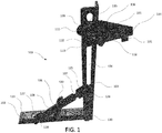
Figure 1 is an image of the bracket for supporting formwork according to an embodiment of the invention; -
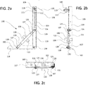
Figure 2a is a schematic side view of the bracket; -
Figure 2b is a schematic front view of the bracket; -
Figure 2c is a schematic top view of the bracket; -
Figure 3a is schematic side view of the bracket used with a short formwork panel; -
Figure 3b is a schematic side view of the bracket used with a tall formwork panel; -
Figure 4a is a schematic front view of a system according to an embodiment of the invention; -
Figure 4b is a schematic front view of an infill panel; -
Figure 4c is a schematic top view of an inner corner joint; -
Figure 4d is a schematic top view of an outer corner joint; -
Figure 5 is a schematic side view of the system including a concrete slab; and -
Figures 6a to e shows the process of installing the system. - Referring to
Figure 1 , abracket 100 for supportingformwork 200 is shown. Thebracket 100 comprises a formation for engaging with a corresponding formation on theformwork 200. The formation for engagement is a lug 101 (that is, a projection for engaging with a corresponding recess on the formwork). By means of the engagement formation, thebracket 100 may be able securely to engage and support formwork. The formwork used with the bracket may be traditional timber shuttering or other such formwork (being adapted so as to include a suitable formation), or dedicated panels, as will be described later on. - The bracket further comprises a
first bracket member 102, asecond bracket member 103, anengagement member 105 on which thelug 101 is mounted, and abrace member 106. The members are all connected so as to provide a complete linkage which may readily be located against formwork and moved into position (as will be described later on). In other words, when not in situ, the members of thebracket 100 remain connected. This means that the bracket should stay in one piece, which reduces the likelihood of lost parts. - The
engagement member 105 is the part of the bracket which engages with the formwork. Said engagement is preferably from above (i.e. with an upper part or surface of the formwork), so as to allow other parts of the bracket to bear against an outer side of the formwork without interference from engagement components, and to avoid locating parts of the bracket against an inner side of the framework (which may interfere with the concrete pour). - The
engagement member 105 is formed as a flat plate with five straight edges. Afirst edge 112 is the longest and is positioned on the bottom of theengagement member 105 when in use. Asecond edge 113 and athird edge 114 extend upwards from the ends of thefirst edge 112, when in use, wherein thethird edge 114 is shorter than, and parallel to, thesecond edge 113. Afourth edge 115 is positioned on the top of theengagement member 105 when in use wherein thefourth edge 115 is parallel to, and shorter than, thefirst edge 112. Afifth edge 116 connects thefourth edge 115 and thethird edge 114 at an angle to thefourth edge 115. The angle of thefifth edge 116 removes one of the outlying sharp corners of thebracket 100, which may improve the overall safety of thebracket 100 when in use. Specifically, theengagement member 105 is a 150mm by 75mm by 6mm thick sheet, with a corner cut off so as to provide thefifth edge 116. - The
lug 101 is a protrusion which extends from thefirst edge 112 of theengagement member 105. Thelug 101 is a plate which preferably has a rectangular cross-section, which may improve the rigidity of the connection to a corresponding formation on theformwork 200. It is also possible for thelug 101 to extend from any of the other four edges. Thelug 101 is centred 125mm from thesecond edge 113 of theengagement member 105. The lug itself has the dimensions 20mm x 14mm x 10mm. Preferably, the lug is wider (at 10mm) than the engagement member to which it is attached, which is generally 6mm wide. - As mentioned, the
bracket 100 comprises thefirst bracket member 102 and thesecond bracket member 103. Thefirst bracket member 102 and thesecond bracket member 103 are connected at their ends. In use, thefirst bracket member 102 and thesecond bracket member 103 are arranged generally perpendicular to each other, so as to form an L-shape in use. The engagement member is attached to thesecond bracket member 103 away from the connection with thefirst bracket member 102, as will be described later on. - At the connection between the
first bracket member 102 and thesecond bracket member 103 there is a joint, at which thefirst bracket member 102 and thesecond bracket member 103 are free to rotate about an axis. The axis is defined by a pin or bolt 130 which extends through a hole in thefirst bracket member 102 and a hole in thesecond bracket member 103. The pin or bolt 130 is secured to thefirst bracket member 102 and thesecond bracket member 103 by a nut. Thebolt 130 is preferably an M10 bolt with a lock nut. Thebolt 130 allows free rotation of thefirst bracket member 102 relative to thesecond bracket member 103, so it is possible for thefirst bracket member 102 and thesecond bracket member 103 to not be generally perpendicular to each other when not in us. This is useful as it can reduce the overall size of thebracket 100 for storage and transport. It also allows the bracket to be plumbed into the correct position during use, as shown inFigures 6a-e . - The
first bracket member 102 and thesecond bracket member 103 comprise beams having an L-shaped cross-section. As such, thefirst bracket member 102 comprises afirst surface 117 which is flat and horizontal, which allows thebracket 100 to be joined to theunderlying structure 300. Thefirst bracket member 102 further comprises asecond surface 118, which can be joined to afirst surface 119 of thesecond bracket member 103 to join thefirst bracket member 102 to thesecond bracket member 103 at the connection joint. Washers are used at the connection joint to allow thefirst bracket member 102 and thesecond bracket member 103 to rotate freely about the axis. Thesecond bracket member 103 further comprises asecond surface 120, which abuts against theformwork 200 in use. Thesecond bracket member 103 may also be coupled to theformwork 200 through five nails passing through five5mm holes 121 in thesecond bracket member 103. The five5mm holes 121 in thesecond bracket member 103 are separated 100mm apart. The flat surfaces provided by the L-shaped cross-section may help to keep thebracket 100 square and level with respect to anunderlying structure 300 and theformwork 200. Thefirst bracket member 102 is preferably formed of 75mm x 50mm x 5mm unequal angle, whereas thesecond bracket member 103 is preferably formed of 50mm x 50mm x 5mm equal angle. - In use, the first bracket member 102 (more specifically, the
first surface 117 thereof) forms a base for thebracket 100, where thefirst member 102 comprisesapertures 123 to enable fixing of thebracket 100 to an underlying structure 300 (e.g. falsework, or the ground). Specifically, thefirst bracket member 102 comprises nine5mm apertures 123 spaced 100mm apart on thefirst surface 117 of thefirst bracket member 102. The length of thefirst bracket member 102 is preferably 400mm - this length may be advantageous in that it provides security of attachment to an underlying structure while not being so long as to present a significant trip hazard. A corner of thesecond surface 118 distal to thesecond bracket member 103 may be removed to further reduce the trip hazard of thebracket 100. - When in use, the
second bracket member 103 abuts theformwork 200 and extends along a height of the formwork, so as to resist the hydrostatic pressure of the wet concrete. As mentioned, thelug 101 engages with the formwork from above - accordingly, thesecond bracket member 103 is generally taller than the formwork. The length of thesecond bracket member 103 is preferably 600mm. - The
engagement member 105 is connected to thesecond bracket member 103 and is moveable relative to thesecond bracket member 103 thereby to allow adjustment of the height of theengagement member 105. This allows thebracket 100 to be used for a range of formwork heights. Specifically, the formwork heights that can be used range between 300mm to 450mm. Theengagement member 105 also rotatable relative to thesecond bracket member 103, which allows for flexibility (i.e. 'play') in the positioning of thelug 101 into theformwork 200. - The connection between the
engagement member 105 and thesecond bracket member 103 is provided by aslot 104 disposed in thefirst surface 118 of thesecond bracket member 103. Theengagement member 105 further comprises a lockingmember 109, apin 110 and a lockingnut 111. Theengagement member 105 is connected to thesecond bracket member 103 via thepin 110 which slides in theslot 104 in thesecond bracket member 103. Thesecond bracket member 103 is 600mm long. Theslot 104 is 190mm long and 13mm wide and is positioned centrally in thefirst surface 119 of thesecond bracket member 103, 15mm from the top of thesecond bracket member 103. - The connection between the
engagement member 105 and the lockingmember 109 is maintained when the position of theengagement member 105 is not fixed via the lockingnut 111, as this may keep thebracket 100 in one piece and so reduce the likelihood of lost parts. In particular, the connection between theengagement member 105 and the lockingmember 109 is provided by thepin 110 extending through thesecond bracket member 103; theengagement member 105 and the lockingnut 111 so that there is a closed loop arrangement between the end of thepin 110 and the lockingnut 111. The first end of thepin 110 comprises a wider diameter section than the rest of thepin 110 so that thepin 110 cannot be pulled through thesecond bracket member 103 and theengagement member 105. A section at the second end of thepin 110 is threaded so that it can accept the lockingnut 111. - The locking
nut 111 is used for fixing the position of theengagement member 105 in the slot and so relative to thesecond bracket member 103. The lockingnut 111 is a wingnut, wherein the length of the wings of the wingnut is configured such that the wings do not extend beyond an edge of theengagement member 105. The wings of the lockingnut 111 do not extend beyond thethird edge 114 of theengagement member 105 so thatformwork 200 does not interfere with the rotation of the lockingnut 111. Theengagement member 105 comprises a 13mm hole positioned near the corner of thesecond edge 113 and thefourth edge 115 for fitment of thepin 110. The hole is preferably centred 24mm from thesecond edge 113 and 18mm from thefourth edge 115. - Providing the locking
nut 111 as a wingnut may allow thebracket 100 to be adjusted by hand, or by tapping with a hammer to apply additional torque, to increase the tightness of the lockingnut 111. Thepin 110 is an M12 Speedbolt and the lockingnut 111 is a captive wingnut. Thepin 110 comprises a DW15 thread which requires a quarter turn of the wingnut to loosen or lock theengagement member 105. - As mentioned, the
bracket 100 comprises abrace member 106 extending between thefirst bracket member 102 and thesecond bracket member 103. In use, the brace member resists the hydrostatic pressure of the wet concrete which is poured into the formwork. Thebrace member 106 is connected to thesecond bracket member 103 adjacent to or beneath an end of theslot 104, which may stop thebrace member 106 from interfering with the movement of theengagement member 105. - The
brace member 106 is extendable thereby to allow alteration of an angle between thefirst bracket member 102 and thesecond bracket member 103, which allows for convenient installation of thebracket 100. In particular, thebrace member 106 is extendable via a screw mechanism, by means of thebrace member 106 including a threadedshaft 107 and abody 108 having a threaded aperture. Thebody 108 is a cylindrical tube which is engaged with theshaft 107, which protrudes out of the end of the body. The end of theshaft 107 distal to thebody 108 includes ahead 125 which connects to thesecond bracket member 103 via apin 126. A correspondinghead 127 and pin 128 are provided on the other end of thebody 108, for connection to thefirst bracket member 102. Optionally, thehead 127 and thebody 108 are separated by afurther shaft 129. In an alternative, threaded shafts may be provided on both sides of the body (such that both shafts extend from the body when the body is rotated). - The
aforementioned pins heads brace member 106. Thefirst bracket member 102 and thesecond bracket member 103 have corresponding apertures to align with the apertures in thebrace member 106. In particular, the apertures are 13mm in diameter, and the pins are M12 bolts which extend through the holes to connect thebrace member 106 to thefirst bracket member 102 and thesecond bracket member 103. Lock nuts are used to secure the M12 bolts. - The
shaft 107 andbody 108 engage such that rotation of thebody 108 causes thebrace member 106 to extend (by more of theshaft 107 extending out of the body 108). This allows the angle between thefirst bracket member 102 and thesecond bracket member 103 to be adjusted, which may assist in connecting thebracket 100 to the formwork. - The
brace member 106 further comprises twoflat tabs 122, preferably two 40mm by 35mm flaps, wherein the twoflat tabs 122 extend in the same plane from the sides of thebody 108. The twoflat tabs 122 allow thebody 108 to be rotated more easily by increasing the moment arm. In use, the twoflat tabs 122 may be rotated by hand, or by being hit with a hammer to provide additional torque, to rotate thebody 108 around theshaft 107. The length of the tabs is configured to avoid interference with thebracket members -
Figures 2a to 2c show further views of thebracket 100. Theengagement member 105 is not shown inFigures 2b and 2c , for clarity. -
Figures 3a and 3b show thebracket 100 engaged with aspecialised formwork panel 200. Thepanel 200 is designed to operate with thebracket 100, but it will be appreciated that other (suitably adapted) formwork could alternatively be used. Together, thepanel 200 andbracket 100 form aformwork system 400. - The
panel 200 comprises awall 206 and twoflanges first flange 207 provides the top of thepanel 200; thesecond flange 208 provides the bottom of thepanel 200 and thewall 206 provides a flat surface against which the concrete abuts in use. Thepanel 200 thereby provides a three-sided structure. Thepanel 200 may further comprise ribs 209 (not shown inFigures 3a or 3b ) disposed vertically on the side of thepanel 200 and spaced 300mm apart to provide additional strength. The panels also include end portions 204 (not shown inFigures 3a or 3b ) for connecting theflanges - As mentioned, the
panel 200 comprises a formation for engaging with the corresponding formation on thebracket 100. Theformwork 200 formation comprises arecess 202 for receiving thecorresponding lug 101. Therecess 202 is part of a profiled edge which extends along anupper surface 201 of thefirst flange 207. In use, theengagement member 105 is brought into contact with theupper surface 201 from above so that thelug 101 engages with therecess 202. - The
recess 202 comprises a trapezoidal cross-section so that the rectangular or square shape of thelug 101 can extend into therecess 202. As shown inFigure 3 , the angled sides of the trapezium cross-section of therecess 202 allow thelug 101 to slide into therecess 202 even if it has not been perfectly aligned. This flexibility in the construction process may improve the usability of thebracket 100 andpanel 200. As therecess 202 extends along the formwork, a plurality ofbrackets 100 may be attached to thepanel 200. - In use, the
panel 200 is positioned on top of theunderlying structure 300 and abuts thesecond bracket member 103. Thepanel 200 comprises a rectangular cross-section so that the slab edge of the concrete is level and perpendicular to theunderlying structure 300. - It will be appreciated that the adjustable height of the
engagement member 105 allows thebracket 100 to be used withpanels 200 of various sizes.Figure 3a shows thebracket 100 engaged with a smaller panel (300mm in height), andFigure 3b shows thebracket 100 engaged with a larger panel (450mm in height). -
Figure 4a shows asystem 400 formed of a plurality ofpanels 200 andbrackets 100. The view shown inFigure 4a is from the outer side of the formwork. - Each panel may include a fixing, such as a
clamp 205, for connecting thepanel 200 to afurther panel 200. The clamp is generally located adjacent or through theend portions 204 of thepanels 200. Theclamp 205 connects thefirst panel 200 to thesecond panel 200 so that there is no gap between thefirst panel 200 and thesecond panel 200. However, it is also possible that there is a gap between thefirst panel 200 and thesecond panel 200. This gap may be infilled with timber up to a maximum gap size of 150mm. It is also possible that asmall panel 250, without abracket 100, is infilled in the gap which increases the maximum gap size to 300mm. -
Figure 4b shows asmall panel 250 used as an infill. Optionally, this panel is formed from timber and may be formed on-site. Thesmall panel 200 may further comprise a slottedhole 252 of 110mm by 50mm diameter, which acts as a formation for engagement with the bracket. -
Figure 4c shows the joint between twopanels 200 on the inside of the formwork. It is preferable that the inner corner angle, shown by the arrows, is between 60 degrees and 270 degrees. If the angle was smaller than 60 degrees then the concrete may not fully fill into the mould corner. -
Figure 4d shows the joint between twopanels 200 on the outside of the formwork. It is preferable that the outer corner angle, shown by the arrows, is between 60 degrees and 135 degrees. If the angle was smaller than 60 degrees thenpanels 200 may overlap. - As will be appreciated,
panels 200 may have various sizes for use with different concrete slabs shapes and sizes. Generally, the length of thepanels 200 can range between 300mm to 3300mm. Thebrackets 100 are generally positioned along thepanel 200 between 900mm and 1200mm apart to allow the hydrostatic load to be spread effectively. If thepanel 200 is less than 900mm long then asingle bracket 100 may be positioned in the centre of thepanel 200. This positioning ofbrackets 100 aims to give thesystem 400 sufficient strength to hold up against the concrete slab as it sets. It will be appreciated that a continuous edge including therecess 202 is formed between thepanels 200, so the number and location ofbrackets 100 used with thesystem 400 may be varied depending on the use-case. -
Figure 5 shows thesystem 400 including aconcrete slab 203 andfalsework 300. As mentioned, thefirst bracket member 102 forms a base for thebracket 100. If the underlying structure used asfalsework 300 is wood then nine screws (4.2mm diameter and 50mm length) are inserted into the nine5mm holes 123 in thefirst bracket member 102 and secured into theunderlying structure 300. If the underlying structure is concrete then two bolts (M16 and 50mm length) are inserted into the two slotted holes in thefirst bracket member 102 and secured into theunderlying structure 300. This aims to provide thebracket 100 with sufficient strength to stop movement relative to theunderlying structure 300 during the slab pouring process. Once thesystem 400 is assembled the concrete is poured into the mould created by theformwork 200. Once the mould as set and/or the surrounding construction has been completed, thesystem 400 and theunderlying falsework 300 may be removed. -
Figures 6a-e show the way in which theformwork system 400 is set up and used in the formation of a concrete slab edge. As thebracket 100 is in one piece, there is generally no need to assemble the support for theformwork 200 on-site, which may save time. -
Figure 6a shows thepanel 200 installed on theunderlying structure 300. Thepanel 200 may not secured to theunderlying structure 300 by any fixing means at this point. Alternatively, thepanel 200 may be attached to theunderlying structure 300 by conventional means. The dotted line represents the future position of theconcrete slab 203. -
Figure 6b shows thebracket 100 installed onto theunderlying structure 300, wherebolts 131 are used to engage thefirst bracket member 103 to theunderlying structure 300. Before thebracket 100 is assembled to theunderlying structure 300 thebrace member 106 is shortened to pull thesecond bracket member 103 back to reduce the angle between thefirst bracket member 102 and thesecond bracket member 103. Thebrace member 106 is shortened by rotating thebody 108 relative to theshaft 107, wherein the screw mechanism causes thebody 108 to further overlap theshaft 107. As such, as shown inFigure 6b , thesecond engagement member 103 is initially at an oblique angle relative to thepanel 200. Theengagement member 105 is secured in a position on thesecond bracket member 103 so that when thebrace member 106 is extended theengagement member 105 is above and clear of thepanel 200. -
Figure 6c shows thesecond bracket member 103 after being pushed upright by thebrace member 106 and theengagement member 105 about to lower to engage with theformwork 200 from above. Firstly, thebody 108 of thebrace member 106 is rotated so that thebrace member 106 extends causing the angle between thefirst bracket member 102 and thesecond bracket member 103 to increase. Thebrace member 106 is extended so that the entiresecond surface 120 of thesecond bracket member 103 abuts thepanel 200. Optionally, thesecond bracket member 103 may be coupled to theformwork 200 via five nails extended through the five5mm holes 121 in thesecond bracket member 103. Secondly, the lockingnut 111 is loosened to allow theengagement member 105 to slide freely. Thirdly, theengagement member 105 is lowered towards theformwork 200 so that thelug 101 extends into therecess 202. Finally, once thelug 101 is securely fitted into therecess 202, the lockingnut 111 is tightened to secure theengagement member 105 into place. -
Figure 6d shows thelug 101 extended into therecess 202 and the length of thebrace member 106 being adjusted so that thesecond bracket member 103 is substantially vertical. This process of adjusting thebrace member 106 so that thesecond bracket member 103 is substantially vertical is known in the industry as plumbing. This is because the plumbing is commonly carried out using a mass on the end of a string known as a plumb bob and line. This final extension of thebrace member 106 provides for improved plumbing while allowing a secure engagement between thebracket 100 andpanel 200 to be made. In an alternative, the steps shown inFigure 6c and 6d may be somewhat iterative, i.e. a user may fix the recess in position, plumb the bracket, adjust the recess position, plumb further, etc. -
Figure 6e shows thesystem 400 once the concrete slab has been poured into the mould formed by theformwork 200. Once all of thebrackets 100 have been plumbed and checked that they are substantially vertical then the concrete is poured into the mould formed for theconcrete slab 203. After the concrete slab has set thesystem 400 is disassembled. The disassembly involves removing thebrackets 100 from theformwork 200 followed by breaking away theformwork 200 from theconcrete slab 203. - The
bracket 100, including all members, is preferably formed from steel, and more preferably are coated in a corrosion resistant coating such as paint, or otherwise may be galvanised. - It will be appreciated that in an alternative, different engagement formations on the
bracket 100 andpanel 200 may be used. For example, it may be suitable for thelug 101 to comprise a protrusion such as a cylindrical or cuboid protrusion. The previously describedrecess 202 may also be suitable for accepted thealternative lug 101. Therecess 202 may also comprise a different cross-section such as a rectangular cross-section, a semi-circular cross-section or a triangular cross-section. Furthermore, it is not essential that therecess 202 extends along the entire length of thepanel 200. It may be suitable for therecess 202 to only be provided in thepanel 200 where thebracket 100 will be attached. The formations may alternatively be reversed, such that the panel comprises a lug and the bracket comprises a recess for fitment of the lug. Other examples of alternative engagement formations include corresponding apertures fastened by a bolt, a latch system, and a clamp which engages with a corresponding shaped portion. - In an alternative, the
first bracket member 102 may comprise a different cross-section such as a T-shaped cross-section. The T-shaped cross-section would provide an additional surface to couple thebracket 100 to theunderlying structure 300. It may even provide a more secure coupling between thebracket 100 and theunderlying structure 300. - The
first bracket member 102 and thesecond bracket member 103 could alternatively comprise a square or rectangular cross-section which may provide more strength to thebracket 100. - In an alternative, the
slot 104 may include notches located along the length of theslot 104 so that theengagement member 105 could be set to a pre-set height. - The
bracket 100 could have material removed from the members to reduce the weight of thebracket 100. This could be carried out by Finite Element Analysis (FEA) topology optimisation wherein structure of the member is positioned in a preferable location so as to resist against the imposed forces. - The
brace member 106 is shown to comprise a threadedshaft 107 and abody 108 wherein thebody 108 is rotated in relation to theshaft 107 to adjust the length of thebrace member 106. Thebrace member 106 could be adjusted in length by other means, such as a notchedshaft 107 andbody 108, a friction fittelescopic shaft 107 andbody 108, or by a spring loaded pin wherein the pin extends from theshaft 107 through one hole in a plurality of holes in thebody 108. - Although the invention has generally been described with reference to the bracket engaging with the panel from above, in an alternative the bracket could engage with the panel from a side of the panel.
- The
panels 200 shown may be provided in various different shapes to allow for differently shaped slabs to be produced. In particular, panels including corners may be provided. - Although the invention has principally been described with reference to supporting formwork for slab edge production, it will be appreciated that the bracket, panel and system could be used in various other formwork applications, or indeed in any other application where temporary moulds are used.
- It will be understood that the invention has been described above purely by way of example, and modifications of detail can be made within the scope of the invention.
- Expressions such as "including", "comprising", "incorporating", "have", "is" used to describe and claim the present disclosure are intended to be construed in a nonexclusive manner, namely allowing for items, components or elements not explicitly described also to be present. Reference to the singular is also to be construed to relate to the plural.
- Each feature disclosed in the description, and (where appropriate) the claims and drawings may be provided independently or in any appropriate combination.
- Reference numerals appearing in the claims are by way of illustration only and shall have no limiting effect on the scope of the claims.
Claims (15)
- A bracket for supporting formwork; comprising a formation for engaging with a corresponding formation on formwork.
- A bracket according to Claim 1, wherein the engagement formation is a lug; preferably wherein the lug has a rectangular cross-section.
- A bracket according to any preceding claim, further comprising a first bracket member and a second bracket member.
- A bracket according to Claim 3, further comprising an engagement feature for engaging with the formwork.
- A bracket according to Claim 4, further comprising a brace member extending between the first bracket member and the second bracket member.
- A bracket for supporting formwork; comprising:a first bracket member;a second bracket member;a brace member extending between the first bracket member and the second bracket member; andan engagement feature for engaging with formwork; preferably wherein the engagement feature comprises a formation for engaging with a corresponding formation on formwork, more preferably wherein the engagement formation is a lug, yet more preferably wherein the lug has a rectangular cross-section.
- A bracket according to Claim 3 to 6, wherein, in use, said first bracket member and said second bracket member are arranged generally perpendicular to each other, preferably wherein the first bracket member and the second bracket member are connected at respective ends of the members; and/or wherein, in use, the second bracket member abuts the formwork and preferably extends along a height of the formwork; and/or wherein, in use, the first bracket member forms a base for the bracket, preferably wherein the first bracket member comprises apertures to enable fixing of the bracket to an underlying structure; and/or wherein the first bracket member and second member comprise beams having an L-shaped cross-section.
- A bracket according to any of Claims 4 to 6 or Claim 7 when dependent on any of Claims 4 to 6, wherein the engagement feature is provided on an engagement member connected to the second bracket member; preferably wherein the engagement member is at least one of: moveable relative to the second bracket member thereby to allow adjustment of the height of the engagement member; and rotatable relative to the second bracket member.
- A bracket according to Claim 8, wherein the engagement member is connected to the second bracket member via a pin which slides in a slot in the second bracket member; and/or wherein the bracket further comprises a locking nut for fixing the position of the engagement member relative to the second bracket member, preferably wherein the connection between the engagement member and the second bracket member is maintained when the position of the engagement member is not fixed via the locking nut, more preferably wherein the locking nut is a wingnut, and yet more preferably wherein the length of the wings of the wingnut is configured such that the wings do not extend beyond an edge of the engagement member.
- A bracket according to Claim 9 when dependent on Claim 5 or 6, wherein the brace member is connected to the second bracket member adjacent to or beneath an end of the slot.
- A bracket according to Claim 5 or 6 or Claims 7 to 10 when dependent on Claim 5 or 6, wherein the brace member is extendable thereby to allow alteration of an angle between the first bracket member and the second bracket member; preferably wherein the brace member is extendable via a screw mechanism; more preferably wherein the brace member comprises a threaded shaft and a body having a threaded aperture, wherein the shaft and body engage such that rotation of the body causes the brace member to extend.
- A bracket according to any of Claims 3 to 11, wherein the members are connected as a mechanical linkage; preferably wherein the members remain connected when the bracket is not in situ.
- A bracket according to any preceding claim, wherein, in use, the bracket engages with the formwork from above.
- Formwork, comprising a formation for engaging with a corresponding formation on a bracket for supporting the formwork; preferably: wherein the formation is provided at multiple locations on the formwork; and/or wherein the formation comprises a recess for receiving the corresponding formation, more preferably wherein the recess is a profiled edge extending along the formwork, yet more preferably wherein an opening of the recess is wider than a base of the recess, still more preferably wherein the recess has a trapezoidal cross section; and/or wherein the formwork is a panel for slab edge formwork; more preferably further comprising a fixing for connecting to further panels.
- A system; comprising at least one formwork according to Claim 14 and at least one bracket for supporting formwork according to any of Claims 1 to 13; preferably wherein the engagement formation of the formwork is configured to engage with the engagement formation of the bracket..
Applications Claiming Priority (1)
| Application Number | Priority Date | Filing Date | Title |
|---|---|---|---|
| GB1916222.1A GB2589079B (en) | 2019-11-07 | 2019-11-07 | Bracket for supporting formwork; formwork; and system |
Publications (1)
| Publication Number | Publication Date |
|---|---|
| EP3819442A1 true EP3819442A1 (en) | 2021-05-12 |
Family
ID=69062224
Family Applications (1)
| Application Number | Title | Priority Date | Filing Date |
|---|---|---|---|
| EP20206246.9A Pending EP3819442A1 (en) | 2019-11-07 | 2020-11-06 | Bracket for supporting formwork; formwork; and system |
Country Status (2)
| Country | Link |
|---|---|
| EP (1) | EP3819442A1 (en) |
| GB (1) | GB2589079B (en) |
Cited By (1)
| Publication number | Priority date | Publication date | Assignee | Title |
|---|---|---|---|---|
| CN119472451A (en) * | 2025-01-07 | 2025-02-18 | 克劳斯玛菲机械(中国)有限公司 | Upper mold frame rotation control system and control method |
Citations (4)
| Publication number | Priority date | Publication date | Assignee | Title |
|---|---|---|---|---|
| FR1175132A (en) * | 1957-05-15 | 1959-03-20 | Formwork method for walls and other parts of buildings, and formwork and other arrangements for implementing the method | |
| GB1142881A (en) * | 1966-04-29 | 1969-02-12 | Rapid Metal Developments Ltd | Formwork supporting means |
| US5843327A (en) * | 1990-06-15 | 1998-12-01 | Lindgren; Haakan | Casting mold device |
| WO2001096690A1 (en) * | 2000-06-16 | 2001-12-20 | Australian Consulting & Training Pty Ltd | Method and arrangement for forming construction panels and structures |
Family Cites Families (8)
| Publication number | Priority date | Publication date | Assignee | Title |
|---|---|---|---|---|
| US2313880A (en) * | 1941-08-29 | 1943-03-16 | Clyde Averitt | Concrete wall form |
| DE2423556A1 (en) * | 1974-05-15 | 1975-11-20 | Acrow Wolff Gmbh | Concrete column or support formwork - in mobile form with fitting carriage with adjustable carrier and suspension devices |
| US5076536A (en) * | 1987-02-12 | 1991-12-31 | Fitzgerald Leonard R | Concrete form supporting bracket |
| US20060201743A1 (en) * | 2005-03-11 | 2006-09-14 | Dell Erba Peter H | Brace for concrete forms |
| US20110210234A1 (en) * | 2010-02-26 | 2011-09-01 | Garcia Jr Robert James | Concrete Form Brace |
| JP5808685B2 (en) * | 2012-02-03 | 2015-11-10 | 大成建設株式会社 | Formwork support device |
| AU2014215950B2 (en) * | 2014-08-19 | 2019-09-19 | Form 700 Pty Ltd | Concrete formwork and a formwork support bracket |
| CN208456111U (en) * | 2018-06-20 | 2019-02-01 | 中国水利水电第八工程局有限公司 | Adjustable receipts face mould plate supporting device |
-
2019
- 2019-11-07 GB GB1916222.1A patent/GB2589079B/en active Active
-
2020
- 2020-11-06 EP EP20206246.9A patent/EP3819442A1/en active Pending
Patent Citations (4)
| Publication number | Priority date | Publication date | Assignee | Title |
|---|---|---|---|---|
| FR1175132A (en) * | 1957-05-15 | 1959-03-20 | Formwork method for walls and other parts of buildings, and formwork and other arrangements for implementing the method | |
| GB1142881A (en) * | 1966-04-29 | 1969-02-12 | Rapid Metal Developments Ltd | Formwork supporting means |
| US5843327A (en) * | 1990-06-15 | 1998-12-01 | Lindgren; Haakan | Casting mold device |
| WO2001096690A1 (en) * | 2000-06-16 | 2001-12-20 | Australian Consulting & Training Pty Ltd | Method and arrangement for forming construction panels and structures |
Cited By (1)
| Publication number | Priority date | Publication date | Assignee | Title |
|---|---|---|---|---|
| CN119472451A (en) * | 2025-01-07 | 2025-02-18 | 克劳斯玛菲机械(中国)有限公司 | Upper mold frame rotation control system and control method |
Also Published As
| Publication number | Publication date |
|---|---|
| GB2589079B (en) | 2024-10-02 |
| GB201916222D0 (en) | 2019-12-25 |
| GB2589079A (en) | 2021-05-26 |
Similar Documents
| Publication | Publication Date | Title |
|---|---|---|
| US7908804B2 (en) | Structural lintel assembly and building construction method using the same | |
| US8528275B2 (en) | Ground anchor with adjustable positioning member | |
| KR101310842B1 (en) | Concrete mold assembly and method of constructing beam by using the same | |
| US20020003061A1 (en) | Scaffolding | |
| KR102038061B1 (en) | An assembly type supporting beam mold, and method for constructing this same | |
| WO2009009898A1 (en) | Concrete slab depth varying system | |
| US5085398A (en) | Adjustable form brace | |
| US20110210234A1 (en) | Concrete Form Brace | |
| US20070266659A1 (en) | Perimeter foundation panel, and method of use | |
| US5704171A (en) | Door frame installing fixture | |
| GB2589079A (en) | Bracket for supporting formwork; formwork; and system | |
| KR20130021017A (en) | A shore system of the variable support angle | |
| JP2716357B2 (en) | Rising section formwork fixing jig | |
| JPH06317016A (en) | Formwork device for pillar | |
| JP3038597B2 (en) | Beam form support unit | |
| WO2008025050A1 (en) | Formwork apparatus and method of erecting formwork apparatus | |
| JP2021188361A (en) | Mold frame device for concrete structure and mold frame construction method for concrete structure | |
| KR20220013045A (en) | Easy-to-install integrated slab euroform system | |
| EP2463457A1 (en) | High-precision integral modular formwork system for the construction of monolithic reinforced-concrete structures | |
| KR0152401B1 (en) | Form panel structure | |
| JP7792083B2 (en) | Unit structure and unit structure construction method | |
| JPH11124937A (en) | Lower structure of wall panel, rising hardware, and fitting | |
| JPH0579184A (en) | Beam form shoring unit | |
| JPH04106267A (en) | Column formwork equipment | |
| JP4401018B2 (en) | Support hardware to support concrete formwork |
Legal Events
| Date | Code | Title | Description |
|---|---|---|---|
| PUAI | Public reference made under article 153(3) epc to a published international application that has entered the european phase |
Free format text: ORIGINAL CODE: 0009012 |
|
| STAA | Information on the status of an ep patent application or granted ep patent |
Free format text: STATUS: THE APPLICATION HAS BEEN PUBLISHED |
|
| AK | Designated contracting states |
Kind code of ref document: A1 Designated state(s): AL AT BE BG CH CY CZ DE DK EE ES FI FR GB GR HR HU IE IS IT LI LT LU LV MC MK MT NL NO PL PT RO RS SE SI SK SM TR |
|
| STAA | Information on the status of an ep patent application or granted ep patent |
Free format text: STATUS: REQUEST FOR EXAMINATION WAS MADE |
|
| 17P | Request for examination filed |
Effective date: 20211112 |
|
| RBV | Designated contracting states (corrected) |
Designated state(s): AL AT BE BG CH CY CZ DE DK EE ES FI FR GB GR HR HU IE IS IT LI LT LU LV MC MK MT NL NO PL PT RO RS SE SI SK SM TR |
|
| STAA | Information on the status of an ep patent application or granted ep patent |
Free format text: STATUS: EXAMINATION IS IN PROGRESS |
|
| 17Q | First examination report despatched |
Effective date: 20221221 |
|
| RIN1 | Information on inventor provided before grant (corrected) |
Inventor name: CAREY, MARTIN |