EP3819325A1 - High molecular weight triarylamine compound comprising terphenyl structure in molecular main chain and organic electroluminescent element comprising said high molecular weight compound - Google Patents
High molecular weight triarylamine compound comprising terphenyl structure in molecular main chain and organic electroluminescent element comprising said high molecular weight compound Download PDFInfo
- Publication number
- EP3819325A1 EP3819325A1 EP19830414.9A EP19830414A EP3819325A1 EP 3819325 A1 EP3819325 A1 EP 3819325A1 EP 19830414 A EP19830414 A EP 19830414A EP 3819325 A1 EP3819325 A1 EP 3819325A1
- Authority
- EP
- European Patent Office
- Prior art keywords
- group
- molecular weight
- high molecular
- weight compound
- organic
- Prior art date
- Legal status (The legal status is an assumption and is not a legal conclusion. Google has not performed a legal analysis and makes no representation as to the accuracy of the status listed.)
- Withdrawn
Links
- 0 C*(C)=IC=CC(N(C(C(CC1)=CC2=C1C1=CC=CCC1C2(*)I)=C*)c1ccccc1)=* Chemical compound C*(C)=IC=CC(N(C(C(CC1)=CC2=C1C1=CC=CCC1C2(*)I)=C*)c1ccccc1)=* 0.000 description 2
Images


Classifications
-
- C—CHEMISTRY; METALLURGY
- C09—DYES; PAINTS; POLISHES; NATURAL RESINS; ADHESIVES; COMPOSITIONS NOT OTHERWISE PROVIDED FOR; APPLICATIONS OF MATERIALS NOT OTHERWISE PROVIDED FOR
- C09D—COATING COMPOSITIONS, e.g. PAINTS, VARNISHES OR LACQUERS; FILLING PASTES; CHEMICAL PAINT OR INK REMOVERS; INKS; CORRECTING FLUIDS; WOODSTAINS; PASTES OR SOLIDS FOR COLOURING OR PRINTING; USE OF MATERIALS THEREFOR
- C09D165/00—Coating compositions based on macromolecular compounds obtained by reactions forming a carbon-to-carbon link in the main chain; Coating compositions based on derivatives of such polymers
-
- C—CHEMISTRY; METALLURGY
- C08—ORGANIC MACROMOLECULAR COMPOUNDS; THEIR PREPARATION OR CHEMICAL WORKING-UP; COMPOSITIONS BASED THEREON
- C08G—MACROMOLECULAR COMPOUNDS OBTAINED OTHERWISE THAN BY REACTIONS ONLY INVOLVING UNSATURATED CARBON-TO-CARBON BONDS
- C08G61/00—Macromolecular compounds obtained by reactions forming a carbon-to-carbon link in the main chain of the macromolecule
- C08G61/12—Macromolecular compounds containing atoms other than carbon in the main chain of the macromolecule
-
- H—ELECTRICITY
- H10—SEMICONDUCTOR DEVICES; ELECTRIC SOLID-STATE DEVICES NOT OTHERWISE PROVIDED FOR
- H10K—ORGANIC ELECTRIC SOLID-STATE DEVICES
- H10K50/00—Organic light-emitting devices
- H10K50/10—OLEDs or polymer light-emitting diodes [PLED]
- H10K50/11—OLEDs or polymer light-emitting diodes [PLED] characterised by the electroluminescent [EL] layers
-
- H—ELECTRICITY
- H10—SEMICONDUCTOR DEVICES; ELECTRIC SOLID-STATE DEVICES NOT OTHERWISE PROVIDED FOR
- H10K—ORGANIC ELECTRIC SOLID-STATE DEVICES
- H10K50/00—Organic light-emitting devices
- H10K50/10—OLEDs or polymer light-emitting diodes [PLED]
- H10K50/14—Carrier transporting layers
- H10K50/15—Hole transporting layers
-
- H—ELECTRICITY
- H10—SEMICONDUCTOR DEVICES; ELECTRIC SOLID-STATE DEVICES NOT OTHERWISE PROVIDED FOR
- H10K—ORGANIC ELECTRIC SOLID-STATE DEVICES
- H10K85/00—Organic materials used in the body or electrodes of devices covered by this subclass
- H10K85/10—Organic polymers or oligomers
- H10K85/111—Organic polymers or oligomers comprising aromatic, heteroaromatic, or aryl chains, e.g. polyaniline, polyphenylene or polyphenylene vinylene
-
- H—ELECTRICITY
- H10—SEMICONDUCTOR DEVICES; ELECTRIC SOLID-STATE DEVICES NOT OTHERWISE PROVIDED FOR
- H10K—ORGANIC ELECTRIC SOLID-STATE DEVICES
- H10K85/00—Organic materials used in the body or electrodes of devices covered by this subclass
- H10K85/10—Organic polymers or oligomers
- H10K85/111—Organic polymers or oligomers comprising aromatic, heteroaromatic, or aryl chains, e.g. polyaniline, polyphenylene or polyphenylene vinylene
- H10K85/115—Polyfluorene; Derivatives thereof
-
- H—ELECTRICITY
- H10—SEMICONDUCTOR DEVICES; ELECTRIC SOLID-STATE DEVICES NOT OTHERWISE PROVIDED FOR
- H10K—ORGANIC ELECTRIC SOLID-STATE DEVICES
- H10K85/00—Organic materials used in the body or electrodes of devices covered by this subclass
- H10K85/60—Organic compounds having low molecular weight
- H10K85/631—Amine compounds having at least two aryl rest on at least one amine-nitrogen atom, e.g. triphenylamine
-
- C—CHEMISTRY; METALLURGY
- C08—ORGANIC MACROMOLECULAR COMPOUNDS; THEIR PREPARATION OR CHEMICAL WORKING-UP; COMPOSITIONS BASED THEREON
- C08G—MACROMOLECULAR COMPOUNDS OBTAINED OTHERWISE THAN BY REACTIONS ONLY INVOLVING UNSATURATED CARBON-TO-CARBON BONDS
- C08G2261/00—Macromolecular compounds obtained by reactions forming a carbon-to-carbon link in the main chain of the macromolecule
- C08G2261/10—Definition of the polymer structure
- C08G2261/12—Copolymers
-
- C—CHEMISTRY; METALLURGY
- C08—ORGANIC MACROMOLECULAR COMPOUNDS; THEIR PREPARATION OR CHEMICAL WORKING-UP; COMPOSITIONS BASED THEREON
- C08G—MACROMOLECULAR COMPOUNDS OBTAINED OTHERWISE THAN BY REACTIONS ONLY INVOLVING UNSATURATED CARBON-TO-CARBON BONDS
- C08G2261/00—Macromolecular compounds obtained by reactions forming a carbon-to-carbon link in the main chain of the macromolecule
- C08G2261/10—Definition of the polymer structure
- C08G2261/13—Morphological aspects
- C08G2261/135—Cross-linked structures
-
- C—CHEMISTRY; METALLURGY
- C08—ORGANIC MACROMOLECULAR COMPOUNDS; THEIR PREPARATION OR CHEMICAL WORKING-UP; COMPOSITIONS BASED THEREON
- C08G—MACROMOLECULAR COMPOUNDS OBTAINED OTHERWISE THAN BY REACTIONS ONLY INVOLVING UNSATURATED CARBON-TO-CARBON BONDS
- C08G2261/00—Macromolecular compounds obtained by reactions forming a carbon-to-carbon link in the main chain of the macromolecule
- C08G2261/10—Definition of the polymer structure
- C08G2261/14—Side-groups
- C08G2261/141—Side-chains having aliphatic units
- C08G2261/1412—Saturated aliphatic units
-
- C—CHEMISTRY; METALLURGY
- C08—ORGANIC MACROMOLECULAR COMPOUNDS; THEIR PREPARATION OR CHEMICAL WORKING-UP; COMPOSITIONS BASED THEREON
- C08G—MACROMOLECULAR COMPOUNDS OBTAINED OTHERWISE THAN BY REACTIONS ONLY INVOLVING UNSATURATED CARBON-TO-CARBON BONDS
- C08G2261/00—Macromolecular compounds obtained by reactions forming a carbon-to-carbon link in the main chain of the macromolecule
- C08G2261/10—Definition of the polymer structure
- C08G2261/14—Side-groups
- C08G2261/143—Side-chains containing nitrogen
-
- C—CHEMISTRY; METALLURGY
- C08—ORGANIC MACROMOLECULAR COMPOUNDS; THEIR PREPARATION OR CHEMICAL WORKING-UP; COMPOSITIONS BASED THEREON
- C08G—MACROMOLECULAR COMPOUNDS OBTAINED OTHERWISE THAN BY REACTIONS ONLY INVOLVING UNSATURATED CARBON-TO-CARBON BONDS
- C08G2261/00—Macromolecular compounds obtained by reactions forming a carbon-to-carbon link in the main chain of the macromolecule
- C08G2261/10—Definition of the polymer structure
- C08G2261/14—Side-groups
- C08G2261/148—Side-chains having aromatic units
-
- C—CHEMISTRY; METALLURGY
- C08—ORGANIC MACROMOLECULAR COMPOUNDS; THEIR PREPARATION OR CHEMICAL WORKING-UP; COMPOSITIONS BASED THEREON
- C08G—MACROMOLECULAR COMPOUNDS OBTAINED OTHERWISE THAN BY REACTIONS ONLY INVOLVING UNSATURATED CARBON-TO-CARBON BONDS
- C08G2261/00—Macromolecular compounds obtained by reactions forming a carbon-to-carbon link in the main chain of the macromolecule
- C08G2261/30—Monomer units or repeat units incorporating structural elements in the main chain
- C08G2261/31—Monomer units or repeat units incorporating structural elements in the main chain incorporating aromatic structural elements in the main chain
- C08G2261/312—Non-condensed aromatic systems, e.g. benzene
-
- C—CHEMISTRY; METALLURGY
- C08—ORGANIC MACROMOLECULAR COMPOUNDS; THEIR PREPARATION OR CHEMICAL WORKING-UP; COMPOSITIONS BASED THEREON
- C08G—MACROMOLECULAR COMPOUNDS OBTAINED OTHERWISE THAN BY REACTIONS ONLY INVOLVING UNSATURATED CARBON-TO-CARBON BONDS
- C08G2261/00—Macromolecular compounds obtained by reactions forming a carbon-to-carbon link in the main chain of the macromolecule
- C08G2261/30—Monomer units or repeat units incorporating structural elements in the main chain
- C08G2261/31—Monomer units or repeat units incorporating structural elements in the main chain incorporating aromatic structural elements in the main chain
- C08G2261/316—Monomer units or repeat units incorporating structural elements in the main chain incorporating aromatic structural elements in the main chain bridged by heteroatoms, e.g. N, P, Si or B
- C08G2261/3162—Arylamines
-
- C—CHEMISTRY; METALLURGY
- C08—ORGANIC MACROMOLECULAR COMPOUNDS; THEIR PREPARATION OR CHEMICAL WORKING-UP; COMPOSITIONS BASED THEREON
- C08G—MACROMOLECULAR COMPOUNDS OBTAINED OTHERWISE THAN BY REACTIONS ONLY INVOLVING UNSATURATED CARBON-TO-CARBON BONDS
- C08G2261/00—Macromolecular compounds obtained by reactions forming a carbon-to-carbon link in the main chain of the macromolecule
- C08G2261/40—Polymerisation processes
- C08G2261/41—Organometallic coupling reactions
- C08G2261/411—Suzuki reactions
-
- C—CHEMISTRY; METALLURGY
- C08—ORGANIC MACROMOLECULAR COMPOUNDS; THEIR PREPARATION OR CHEMICAL WORKING-UP; COMPOSITIONS BASED THEREON
- C08G—MACROMOLECULAR COMPOUNDS OBTAINED OTHERWISE THAN BY REACTIONS ONLY INVOLVING UNSATURATED CARBON-TO-CARBON BONDS
- C08G2261/00—Macromolecular compounds obtained by reactions forming a carbon-to-carbon link in the main chain of the macromolecule
- C08G2261/50—Physical properties
- C08G2261/51—Charge transport
- C08G2261/512—Hole transport
-
- C—CHEMISTRY; METALLURGY
- C08—ORGANIC MACROMOLECULAR COMPOUNDS; THEIR PREPARATION OR CHEMICAL WORKING-UP; COMPOSITIONS BASED THEREON
- C08G—MACROMOLECULAR COMPOUNDS OBTAINED OTHERWISE THAN BY REACTIONS ONLY INVOLVING UNSATURATED CARBON-TO-CARBON BONDS
- C08G2261/00—Macromolecular compounds obtained by reactions forming a carbon-to-carbon link in the main chain of the macromolecule
- C08G2261/50—Physical properties
- C08G2261/52—Luminescence
-
- C—CHEMISTRY; METALLURGY
- C08—ORGANIC MACROMOLECULAR COMPOUNDS; THEIR PREPARATION OR CHEMICAL WORKING-UP; COMPOSITIONS BASED THEREON
- C08G—MACROMOLECULAR COMPOUNDS OBTAINED OTHERWISE THAN BY REACTIONS ONLY INVOLVING UNSATURATED CARBON-TO-CARBON BONDS
- C08G2261/00—Macromolecular compounds obtained by reactions forming a carbon-to-carbon link in the main chain of the macromolecule
- C08G2261/50—Physical properties
- C08G2261/59—Stability
- C08G2261/592—Stability against heat
-
- C—CHEMISTRY; METALLURGY
- C08—ORGANIC MACROMOLECULAR COMPOUNDS; THEIR PREPARATION OR CHEMICAL WORKING-UP; COMPOSITIONS BASED THEREON
- C08G—MACROMOLECULAR COMPOUNDS OBTAINED OTHERWISE THAN BY REACTIONS ONLY INVOLVING UNSATURATED CARBON-TO-CARBON BONDS
- C08G2261/00—Macromolecular compounds obtained by reactions forming a carbon-to-carbon link in the main chain of the macromolecule
- C08G2261/70—Post-treatment
- C08G2261/76—Post-treatment crosslinking
-
- C—CHEMISTRY; METALLURGY
- C08—ORGANIC MACROMOLECULAR COMPOUNDS; THEIR PREPARATION OR CHEMICAL WORKING-UP; COMPOSITIONS BASED THEREON
- C08G—MACROMOLECULAR COMPOUNDS OBTAINED OTHERWISE THAN BY REACTIONS ONLY INVOLVING UNSATURATED CARBON-TO-CARBON BONDS
- C08G2261/00—Macromolecular compounds obtained by reactions forming a carbon-to-carbon link in the main chain of the macromolecule
- C08G2261/90—Applications
- C08G2261/95—Use in organic luminescent diodes
-
- H—ELECTRICITY
- H10—SEMICONDUCTOR DEVICES; ELECTRIC SOLID-STATE DEVICES NOT OTHERWISE PROVIDED FOR
- H10K—ORGANIC ELECTRIC SOLID-STATE DEVICES
- H10K50/00—Organic light-emitting devices
- H10K50/10—OLEDs or polymer light-emitting diodes [PLED]
- H10K50/17—Carrier injection layers
-
- H—ELECTRICITY
- H10—SEMICONDUCTOR DEVICES; ELECTRIC SOLID-STATE DEVICES NOT OTHERWISE PROVIDED FOR
- H10K—ORGANIC ELECTRIC SOLID-STATE DEVICES
- H10K50/00—Organic light-emitting devices
- H10K50/10—OLEDs or polymer light-emitting diodes [PLED]
- H10K50/18—Carrier blocking layers
-
- H—ELECTRICITY
- H10—SEMICONDUCTOR DEVICES; ELECTRIC SOLID-STATE DEVICES NOT OTHERWISE PROVIDED FOR
- H10K—ORGANIC ELECTRIC SOLID-STATE DEVICES
- H10K50/00—Organic light-emitting devices
- H10K50/10—OLEDs or polymer light-emitting diodes [PLED]
- H10K50/18—Carrier blocking layers
- H10K50/181—Electron blocking layers
Definitions
- the present invention relates to a high molecular weight compound that is suitable for use in an organic electroluminescent element (organic EL element) that is a self-emissive element that is preferably used in various types of display apparatuses, and the organic electroluminescent element.
- organic electroluminescent element organic EL element
- organic electroluminescent element organic electroluminescent element
- organic EL elements that are self-emissive elements and thus are brighter than liquid crystal elements, have excellent display viewability, and can provide a clear display.
- An organic EL element has a configuration in which a thin film (organic layer) made of an organic compound is interposed between an anode and a cathode.
- the method for forming the thin film can be roughly classified into a vacuum deposition method and a coating method.
- the vacuum deposition method is a method in which a thin film is formed on a substrate in vacuum using mainly a low molecular compound, and is a technique that is already in practical use.
- the coating method is a method in which a thin film is formed on a substrate through inkjet printing or printing using a solution composed mainly of a polymer. This method is a technique that is essential for future large area organic EL displays because it has high material usage efficiency and is suitable for larger area and higher resolution displays.
- the vacuum deposition method in which a low molecular material is used has very low material usage efficiency. Accordingly, if the vacuum deposition method is used to produce a large substrate, there may be significant warping of a shadow mask, which makes it difficult to deposit a uniform thin film on a large substrate. There is also the issue of the production cost being high.
- a uniform film can be formed even on a large substrate by applying a solution prepared by dissolving the polymer material in an organic solvent.
- a coating method as typified by an inkjet printing method or a printing method can be used. Accordingly, the material usage efficiency can be increased, and thus the cost of producing elements can be reduced significantly.
- TFB fluorene polymer
- a fluorene polymer called TFB is known as a typical hole transport material that has been used in organic EL polymer elements (see Patent Literatures 6 and 7).
- TFB has insufficient hole transportability and insufficient electron blockability. Accordingly, there is a problem in that some electrons pass through a light emitting layer, and thus an improvement in light emission efficiency cannot be expected.
- TFB has low film adhesion to adjacent layers, and thus an increase in the lifespan of elements cannot be expected.
- the inventors of the present invention noticed that a triarylamine having a terphenyl structure in its molecular main chain has high hole injection/transport capability and is expected to realize a wide bandgap, and conducted studies by synthesizing high molecular weight triarylamine compounds including various terphenyl structural units. As a result, they found a high molecular weight compound with a novel structure that has, in addition to the hole injection/transport capability, a wide bandgap, excellent heat resistance, and thin film stability. The present invention has thereby been accomplished.
- the present invention provides a high molecular weight compound including a repeating unit represented by a general formula (3) below which is constituted by a triarylamine structural unit represented by a general formula (1) below and a bonding structural unit represented by a general formula (2) below.
- the present invention further provides an organic EL element having a pair of electrodes and at least one organic layer interposed therebetween, the at least one organic layer containing the above-described high molecular weight compound as a constituent material.
- the organic layer is a hole transport layer, an electron blocking layer, a hole injection layer, or a light emitting layer.
- the present invention is as follows.
- the high molecular weight compound according to the present invention that includes the triarylamine structural unit (divalent group) represented by the general formula (1) above and the bonding structural unit (divalent group) represented by the general formula (2) is, for example, a polymer that includes the structural unit as a repeating unit, and preferably has a weight average molecular weight of 10,000 or more and less than 1,000,000 on a polystyrene basis measured using GPC (gel permeation chromatography).
- An organic EL element in which an organic layer made of the high molecular weight compound described above such as, for example, a hole transport layer, an electron blocking layer, a hole injection layer, or a light emitting layer is formed between a pair of electrodes has the following advantages:
- Both of a triarylamine structural unit and a bonding structural unit included in the high molecular weight compound according to the present invention are divalent groups, and are respectively represented by general formulae (1) and (2) below.
- R 1 each independently represents a hydrogen atom, a heavy hydrogen atom, a cyano group, a nitro group, a fluorine atom, a chlorine atom, a bromine atom, an iodine atom, an alkyl group or an alkyloxy group with 1 to 8 carbon atoms, a cycloalkyl group or a cycloalkyloxy group with 5 to 10 carbon atoms, an alkenyl group with 2 to 6 carbon atoms, or an aryloxy group.
- examples of the alkyl group, the alkyloxy group, the cycloalkyl group, the cycloalkyloxy group, the alkenyl group, and the aryloxy group described above include the following groups:
- the above-described R 1 is preferably a hydrogen atom or a heavy hydrogen atom, and more preferably a hydrogen atom in view of synthesizing.
- R 2 each independently represents an alkyl group or an alkyloxy group with 1 to 8 carbon atoms, or a cycloalkyl group or a cycloalkyloxy group with 5 to 10 carbon atoms.
- examples of the alkyl group, the alkyloxy group, the cycloalkyl group, and the cycloalkyloxy group described above include groups that are similar to those represented by R 1 .
- the above-described R 2 is preferably an alkyl group with 1 to 8 carbon atoms, and more preferably an n-hexyl group or an n-octyl group, in view of enhancing the solubility.
- a represents an integer of 0 to 3
- b represents an integer of 0 to 4.
- X represents a hydrogen atom, an amino group, a monovalent aryl group, or a monovalent heteroaryl group.
- examples of the monovalent aryl group and the monovalent heteroaryl group include the following groups:
- the amino group, the aryl group, and the heteroaryl group described above may have a substituent group.
- substituent group include, in addition to a heavy hydrogen atom, a cyano group, a nitro group, and the like, the following groups:
- the substituent groups listed above may further have any of the substituent groups listed above.
- substituent groups are each independently present.
- substituent groups may be bonded to each other to form a ring via a single bond, a methylene group that may have a substituent group, an oxygen atom, or a sulfur atom.
- the aryl group and the heteroaryl group described above may have a phenyl group as a substituent group.
- the phenyl group may further have a phenyl group as a substituent group. That is, in the case of an aryl group, the aryl group may be a biphenylyl group, a terphenylyl group, or a triphenylenyl group.
- L represents a divalent phenyl group
- n represents an integer of 0 to 3.
- the above-described L may have a substituent group.
- substituent group examples include groups that are similar to the substituent groups that can be included in the above-described X, and these substituent groups may further have a substituent group.
- each broken line indicates a bond to an adjacent structural unit
- each solid line that extends from a ring and has a free end indicates that the free end is a methyl group.
- the high molecular weight compound according to the present invention including the repeating unit represented by the general formula (3) which is constituted by the triarylamine structural unit represented by the general formula (1) above and the bonding structural unit represented by the general formula (2), has excellent characteristics such as hole injection characteristics, hole mobility, electron blocking capability, thin film stability, and heat resistance.
- the high molecular weight compound has, for example, a weight average molecular weight on a polystyrene basis measured using GPC, preferably in a range of 10,000 or more and less than 1,000,000, more preferably in a range of 10,000 or more and less than 500,000, and even more preferably in a range of 10,000 or more and less than 200,000.
- the high molecular weight compound is preferably a copolymer of the above-described structural unit and another structural unit.
- the other structural unit may be, for example, a thermal crosslinkable structural unit, and a triarylamine structural unit that is different from that represented by the general formula (1).
- the thermal crosslinkable structural unit is a structural unit having a reactive functional group such as a vinyl group or a cyclobutane ring therein, and specific examples are shown as formulae (4a) to (4z) in Figs. 4 and 5 . Although they are specific examples preferably used as a thermal crosslinkable structural unit, the thermal crosslinkable structural unit used in the present invention is not limited to these structural units.
- each broken line indicates a bond to an adjacent structural unit
- each solid line that extends from a ring and has a free end indicates that the free end is a methyl group.
- R 1 , R 2 , a, and b are the same as those represented by the general formula (1).
- the other structural unit such as a thermal crosslinkable structural unit or a triarylamine structural unit that is different from that represented by the general formula (1) may be contained alone in the high molecular weight compound according to the present invention, or may be contained in the high molecular weight compound according to the present invention in combination with the above-described bonding structural unit represented by the general formula (2) to form a repeating unit.
- the amount of structural unit A is preferably 1 mol% or more, and more preferably 20 mol% or more.
- the high molecular weight compound according to the present invention includes the structural unit A in the above-described amount
- the high molecular weight compound includes the structural unit B in an amount of preferably 1 mol% or more, and more preferably 30 to 70 mol%
- the structural unit C in an amount of preferably 1 mol% or more, and more preferably 5 to 20 mol%.
- the high molecular weight compound according to the present invention is a terpolymer that includes the structural units A, B, and C so as to satisfy the above conditions.
- the high molecular weight compound according to the present invention described above can be synthesized by forming C-C bonds or C-N bonds through a Suzuki polymerization reaction or a HARTWIG-BUCHWALD polymerization reaction so as to connect the structural units.
- the high molecular weight compound according to the present invention can be synthesized by preparing unit compounds that respectively have the above-described structural units, and subjecting the unit compounds to borate esterification or halogenation as appropriate and then to a polycondensation reaction using an appropriate catalyst.
- a triarylamine derivative represented by the following general formula (1a) can be used as the compound for introducing the structural unit represented by the general formula (1).
- Q is a hydrogen atom, a halogen atom, or a borate ester group, and all of R 1 , R 2 , and L are the same as those represented by the general formula (1).
- the unit compound for introducing the structural unit represented by the general formula (1) is obtained.
- Q is a halogen atom or a borate ester group
- a halide or a borate ester used to synthesize a polymer is obtained.
- the halogen atom is preferably Br.
- a copolymer containing 40 mol% of the structural unit A represented by the general formula (1), 50 mol% of the structural unit B represented by the general formula (2), and 10 mol% of the thermal crosslinkable structural unit C (the formula (4e) in Fig. 4 ) is represented by a general formula (5) below.
- This high molecular weight compound can be synthesized through a polycondensation reaction of a borate ester and a halide. It is necessary that an intermediate for introducing the structural unit A and the structural unit C is a borate ester, whereas an intermediate for introducing the structural unit B is a halide, or that an intermediate for introducing the structural unit A and the structural unit C is a halide, whereas an intermediate for introducing the structural unit B is a borate ester. That is to say, the halide and the borate ester have an equal molar ratio.
- the high molecular weight compound according to the present invention described above is dissolved in an aromatic organic solvent such as benzene, toluene, xylene, or anisole so as to prepare a coating solution, and the coating solution is applied to a predetermined substrate to form a coating, and then the coating is heated and dried.
- an aromatic organic solvent such as benzene, toluene, xylene, or anisole
- the coating solution is applied to a predetermined substrate to form a coating, and then the coating is heated and dried.
- a thin film that has excellent characteristics such as hole injectionability, hole transportability, and electron blockability can be formed.
- the thin film also has good heat resistance and good adhesion to other layers.
- the high molecular weight compound described above can be used as a constituent material of a hole injection layer and/or a hole transport layer included in an organic EL element.
- the hole injection layer or the hole transport layer formed using the high molecular weight compound described above has higher hole injectionability, greater mobility, and higher electron blockability than the hole injection layer or the hole transport layer formed using a conventional material.
- the hole injection layer or the hole transport layer formed using the high molecular weight compound described above can confine excitons generated in a light emitting layer, improve the probability of recombination of holes and electrons, and provide high light emission efficiency, and at the same time, achieve advantages of reducing the driving voltage and improving the durability of the organic EL element.
- the high molecular weight compound according to the present invention having the electrical characteristics described above has a bandgap that is wider than that of conventional materials, and is effective to confine excitons, and thus it can also be preferably used as an electron blocking layer or a light emitting layer.
- An organic EL element that includes an organic layer formed using the high molecular weight compound according to the present invention described above has, for example, a structure shown in Fig. 6 .
- a transparent anode 2, a hole injection layer 3, a hole transport layer 4, a light emitting layer 5, an electron transport layer 6, and a cathode 7 are formed on a glass substrate 1 (which may be a transparent substrate such as a transparent resin substrate).
- the layer structure of the organic EL element to which the high molecular weight compound according to the present invention is applied is not limited to that described above.
- a hole blocking layer may be formed between the light emitting layer 5 and the electron transport layer 6.
- an electron blocking layer or the like may be formed between a hole transport layer 11 and a light emitting layer 13 as in the structure shown in Fig. 7 .
- an electron injection layer may be formed between the cathode 7 and the electron transport layer 6.
- some layers may be omitted.
- the organic EL element may have a simple layer structure in which an anode 2, a hole transport layer 4, a light emitting layer 5, an electron transport layer 6, and a cathode 7 are formed on a substrate 1.
- a double-layer structure may be used in which layers having the same function are overlaid.
- the high molecular weight compound according to the present invention is preferably used as a material for forming an organic layer (for example, a hole injection layer 3, a hole transport layer 4, a light emitting layer 5, or an electron blocking layer) that is formed between the anode 2 and the cathode 7.
- an organic layer for example, a hole injection layer 3, a hole transport layer 4, a light emitting layer 5, or an electron blocking layer
- the transparent anode 2 may be made of an electrode material that is known per se, and is formed by depositing an electrode material that has a large work function, such as ITO or gold, on a substrate 1 (a transparent substrate such as a glass substrate).
- the hole injection layer 3 formed on the transparent anode 2 can be formed using a coating solution prepared by dissolving the high molecular weight compound according to the present invention in, for example, an aromatic organic solvent such as toluene, xylene, or anisole. That is, the hole injection layer 3 can be formed by applying the coating solution to the transparent anode 2 through spin coating, inkjet printing, or the like so as to form a coating.
- a coating solution prepared by dissolving the high molecular weight compound according to the present invention in, for example, an aromatic organic solvent such as toluene, xylene, or anisole. That is, the hole injection layer 3 can be formed by applying the coating solution to the transparent anode 2 through spin coating, inkjet printing, or the like so as to form a coating.
- the hole injection layer 3 can also be formed using a conventionally known material, without using the high molecular weight compound according to the present invention.
- the conventionally known material include:
- a layer (thin film) made of any of the materials listed above can be formed through coating using a deposition method, a spin-coating method, an inkjet printing method, or the like. The same applies to other layers. Film-forming is performed using a deposition method or a coating method according to the type of film-forming material.
- the hole transport layer 4 formed on the hole injection layer 3 can also be formed through coating such as spin-coating or inkjet printing using the high molecular weight compound according to the present invention.
- the hole transport layer 4 can also be formed using a conventionally known hole transport material.
- Typical examples of the hole transport material include:
- the compounds for forming a hole transport layer including the high molecular weight compound according to the present invention, may be used alone or in combination of two or more to form a hole transport layer.
- a multi-layer film in which a plurality of layers formed using one or more of the compounds listed above are stacked may be used as the hole transport layer.
- the hole injection layer 3 and the hole transport layer 4 may be combined into one layer.
- Such a hole injection/transport layer can be formed through coating using a polymer material such as PEDOT.
- hole transport layer 4 (the same applies to the hole injection layer 3), a material obtained by p-doping a material usually used to form the layer with trisbromophenylaminehexachloroantimony, a radialene derivative (see, for example, WO 2014/009310 ), or the like can also be used.
- the hole transport layer 4 (or the hole injection layer 3) can also be formed using a polymer that has a TPD base skeleton, or the like.
- an electron blocking layer (which can be provided between the hole transport layer 11 and the light emitting layer 13 as shown in Fig. 7 ) can also be formed through coating such as spin-coating or inkjet printing using the high molecular weight compound according to the present invention.
- an electron blocking layer can also be formed using a known electron blocking compound that has an electron blocking function such as, for example, a carbazole derivative or a compound that has a triphenylsilyl group and a triarylamine structure.
- a carbazole derivative or a compound that has a triphenylsilyl group and a triarylamine structure.
- Specific examples of the carbazole derivative and the compound that has a triarylamine structure are as follows.
- carbazole derivative examples include:
- Examples of the compound that has a triarylamine structure include 9-[4-(carbazole-9-yl)phenyl]-9-[4-(triphenylsilyl)phenyl]-9H-fluorene.
- the electron blocking layer containing the high molecular weight compound according to the present invention, may be used alone or in combination of two or more to form an electron blocking layer.
- a multi-layer film in which a plurality of layers formed using one or more of the compounds listed above are stacked may be used as the electron blocking layer.
- the light emitting layer 5 can be formed using a light emitting material such as a metal complex of a quinolinol derivative such as Alq 3 .
- a light emitting material such as a metal complex of a quinolinol derivative such as Alq 3 .
- Other examples of the light emitting material include various types of metal complexes of zinc, beryllium, aluminum and the like, an anthracene derivative, a bisstyrylbenzene derivative, a pyrene derivative, an oxazole derivative, and a polyphenylene vinylene derivative.
- the light emitting layer 5 can also be formed using a host material and a dopant material.
- a host material in addition to the light emitting materials listed above, a thiazole derivative, a benzimidazole derivative, a polydialkylfluorene derivative, and the like can be used.
- the high molecular weight compound according to the present invention described above can also be used.
- the dopant material quinacridone, coumarin, rubrene, perylene, and derivatives thereof, a benzopyran derivative, a rhodamine derivative, an aminostyryl derivative, and the like can be used.
- the light emitting layer 5 described above may have a single-layer structure in which one or more of the light emitting materials listed above is used, or a multi-layer structure in which a plurality of layers are stacked.
- the light emitting layer 5 can also be formed using a phosphorescent light emitting material as the light emitting material.
- a phosphorescent light emitting material a phosphorescent emitter of a metal complex of iridium, platinum, or the like can be used.
- a green phosphorescent emitter such as Ir(ppy) 3
- a blue phosphorescent emitter such as FIrpic or FIr 6
- a red phosphorescent emitter such as Btp 2 Ir (acac), or the like can be used.
- the phosphorescent light emitting material is used by being doped into a host material that has hole injectionability/transportability or a host material that has electron transportability.
- the host material with the phosphorescent light emitting material through co-deposition in an amount of 1 to 30 wt% relative to the entire light emitting layer.
- a material that emits delayed fluorescence such as a CDCB derivative, specifically, PIC-TRZ, CC2TA, PXZ-TRZ, 4CzIPN, or the like can also be used (see Appl. Phys. Let., 98, 083302 (2011 )).
- the light emitting layer 5 may be formed by causing the high molecular weight compound according to the present invention to carry a fluorescent emitter or a phosphorescent emitter that is called a dopant, or a material that emits delayed fluorescence. In this way, an organic EL element that has a low driving voltage and improved light emission efficiency can be achieved.
- the high molecular weight compound according to the present invention can be used as the host material that has hole injectionability/transportability.
- a carbazole derivative such as 4,4'-di(N-carbazolyl)biphenyl (hereinafter referred to simply as CBP), TCTA, or mCP, or the like can be used.
- the organic EL element including the organic layer formed using the high molecular weight compound according to the present invention as the host material that has electron transportability, p-bis(triphenylsilyl)benzene (hereinafter referred to simply as UGH2), 2,2',2"-(1,3,5-phenylene)-tris(1-phenyl-1H-benzimidazole) (hereinafter referred to simply as TPBI), or the like can be used.
- UGH2 p-bis(triphenylsilyl)benzene
- TPBI 2,2',2"-(1,3,5-phenylene)-tris(1-phenyl-1H-benzimidazole)
- the hole blocking layer (not shown in the diagram) provided between the light emitting layer 5 and the electron transport layer 6 can be formed using a hole blocking compound that is known per se.
- Examples of the known hole blocking compound include:
- These materials can also be used to form an electron transport layer 6, which will be described below, and, furthermore, can be used as a layer obtained by combining the hole blocking layer and the electron transport layer 6.
- the hole blocking layer may also have a single or multi-layer stack structure in which each layer is formed using one or more of the hole blocking compounds listed above.
- the electron transport layer 6 is formed using an electron transport compound that is known per se.
- the known electron transport compound include metal complexes of quinolinol derivatives such as Alq 3 and BAlq, various types of metal complexes, a pyridine derivative, a pyrimidine derivative, a triazole derivative, a triazine derivative, an oxadiazole derivative, a thiadiazole derivative, a carbodiimide derivative, a quinoxaline derivative, a phenanthroline derivative, a silole derivative, a benzimidazole derivative, and the like.
- the electron transport layer 6 may also have a single or multi-layer stack structure in which each layer is formed using one or more of the electron transport compounds listed above.
- the electron injection layer formed optionally can also be formed using a material that is known per se.
- the known material include: alkali metal salts such as lithium fluoride and cesium fluoride; alkaline earth metal salts such as magnesium fluoride; metal oxides such as aluminum oxide; organic metal complexes such as lithium quinoline; and the like.
- the cathode 7 of the organic EL element including the organic layer formed using the high molecular weight compound according to the present invention is formed using an electrode material that has a low work function such as aluminum, or an alloy that has an even lower work function such as a magnesium-silver alloy, a magnesium-indium alloy, or an aluminum-magnesium alloy is used as the electrode material.
- the hole injection layer, the hole transport layer, the light emitting layer, and the electron blocking layer is formed using the high molecular weight compound according to the present invention.
- an organic EL element that has high light emission efficiency, high power efficiency, a low actual driving voltage, a low light-emission start voltage, and outstanding durability can be obtained.
- the organic EL element has a low driving voltage, improved current tolerance, and improved maximum light emission luminance while having high light emission efficiency.
- structural unit represented by the general formula (1) included in the high molecular weight compound according to the present invention will be referred to as "structural unit A”
- structural unit B the bonding structural unit represented by the general formula (2)
- structural unit C the thermal crosslinkable structural unit
- structural unit D the triarylamine structural unit that is different from that represented by the general formula (1)
- the organic layer was washed three times with a saturated saline solution.
- the organic layer was dehydrated using magnesium sulfate anhydrous, and then concentrated under reduced pressure to obtain a crude polymer.
- the crude polymer was dissolved in toluene and adsorbed and purified by adding a silica gel, and then the silica gel was removed through filtering.
- the obtained filtrate was concentrated under reduced pressure, 100 ml of toluene was added to a dried solid to dissolve the dried solid, the resultant was dripped into 300 ml of n-hexane, and a precipitate was obtained through filtering. This operation was repeated three times, and the resultant was dried to obtain 3.5 g (yield 78%) of high molecular weight compound A.
- the average molecular weight measured using GPC and the degree of dispersion of the high molecular weight compound A were as follows.
- Fig. 8 shows the result of 1 H-NMR measurement.
- the chemical composition formula thereof was as follows.
- the high molecular weight compound A contained 40 mol% of the structural unit A represented by the general formula (1), 50 mol% of the structural unit B represented by the general formula (2), and 10 mol% of thermal crosslinkable structural unit C.
- the organic layer was washed three times with a saturated saline solution.
- the organic layer was dehydrated using magnesium sulfate anhydrous, and then concentrated under reduced pressure to obtain a crude polymer.
- the crude polymer was dissolved in toluene and adsorbed and purified by adding a silica gel, and then the silica gel was removed through filtering.
- the obtained filtrate was concentrated under reduced pressure, 120 ml of toluene was added to a dried solid to dissolve the dried solid, the resultant was dripped into 240 ml of n-hexane, and a precipitate was obtained through filtering. This operation was repeated twice, and the resultant was dried to obtain 3.1 g (yield 86%) of high molecular weight compound B.
- the average molecular weight measured using GPC and the degree of dispersion of the high molecular weight compound B were as follows.
- Fig. 9 shows the result of 1 H-NMR measurement.
- the chemical composition formula thereof was as follows.
- the high molecular weight compound B contained 40 mol% of the structural unit A represented by the general formula (1), 50 mol% of the structural unit B represented by the general formula (2), and 10 mol% of thermal crosslinkable structural unit C.
- the organic layer was washed three times with a saturated saline solution.
- the organic layer was dehydrated using magnesium sulfate anhydrous, and then concentrated under reduced pressure to obtain a crude polymer.
- the crude polymer was dissolved in toluene and adsorbed and purified by adding a silica gel, and then the silica gel was removed through filtering.
- the obtained filtrate was concentrated under reduced pressure, 80 ml of toluene was added to a dried solid to dissolve the dried solid, the resultant was dripped into 240 ml of n-hexane, and a precipitate was obtained through filtering. This operation was repeated three times, and the resultant was dried to obtain 3.0 g (yield 80%) of high molecular weight compound C.
- the average molecular weight measured using GPC and the degree of dispersion of the high molecular weight compound C were as follows.
- Fig. 10 shows the result of 1 H-NMR measurement.
- the chemical composition formula thereof was as follows.
- the high molecular weight compound C contained 40 mol% of the structural unit A represented by the general formula (1), 50 mol% of the structural unit B represented by the general formula (2), and 10 mol% of thermal crosslinkable structural unit C.
- the organic layer was washed three times with a saturated saline solution.
- the organic layer was dehydrated using magnesium sulfate anhydrous, and then concentrated under reduced pressure to obtain a crude polymer.
- the crude polymer was dissolved in toluene and adsorbed and purified by adding a silica gel, and then the silica gel was removed through filtering.
- the obtained filtrate was concentrated under reduced pressure, 100 ml of toluene was added to a dried solid to dissolve the dried solid, the resultant was dripped into 300 ml of n-hexane, and a precipitate was obtained through filtering. This operation was repeated three times, and the resultant was dried to obtain 3.2 g (yield 73%) of high molecular weight compound D.
- the average molecular weight measured using GPC and the degree of dispersion of the high molecular weight compound D were as follows.
- Fig. 11 shows the result of 1 H-NMR measurement.
- the chemical composition formula thereof was as follows.
- the high molecular weight compound D contained 40 mol% of the structural unit A represented by the general formula (1), 50 mol% of the structural unit B represented by the general formula (2), and 10 mol% of thermal crosslinkable structural unit C.
- the organic layer was washed three times with a saturated saline solution.
- the organic layer was dehydrated using magnesium sulfate anhydrous, and then concentrated under reduced pressure to obtain a crude polymer.
- the crude polymer was dissolved in toluene and adsorbed and purified by adding a silica gel, and then the silica gel was removed through filtering.
- the obtained filtrate was concentrated under reduced pressure, 100 ml of toluene was added to a dried solid to dissolve the dried solid, the resultant was dripped into 100 ml of n-hexane, and a precipitate was obtained through filtering. This operation was repeated three times, and the resultant was dried to obtain 2.2 g (yield 48%) of high molecular weight compound E.
- the average molecular weight measured using GPC and the degree of dispersion of the high molecular weight compound E were as follows.
- Fig. 12 shows the result of 1 H-NMR measurement.
- the chemical composition formula thereof was as follows.
- the high molecular weight compound E contained 40 mol% of the structural unit A represented by the general formula (1), 50 mol% of the structural unit B represented by the general formula (2), and 10 mol% of thermal crosslinkable structural unit C.
- the organic layer was washed three times with a saturated saline solution.
- the organic layer was dehydrated using magnesium sulfate anhydrous, and then concentrated under reduced pressure to obtain a crude polymer.
- the crude polymer was dissolved in toluene and adsorbed and purified by adding a silica gel, and then the silica gel was removed through filtering.
- the obtained filtrate was concentrated under reduced pressure, 100 ml of toluene was added to a dried solid to dissolve the dried solid, the resultant was dripped into 300 ml of n-hexane, and a precipitate was obtained through filtering. This operation was repeated three times, and the resultant was dried to obtain 3.4 g (yield 75%) of high molecular weight compound F.
- the average molecular weight measured using GPC and the degree of dispersion of the high molecular weight compound F were as follows.
- Fig. 13 shows the result of 1 H-NMR measurement.
- the chemical composition formula thereof was as follows.
- the high molecular weight compound F contained 40 mol% of the structural unit A represented by the general formula (1), 50 mol% of the structural unit B represented by the general formula (2), and 10 mol% of the triarylamine structural unit D that is different from that represented by the general formula (1).
- the high molecular weight compounds A to F according to the present invention exhibited a preferable energy level higher than 5.4 eV that is the work function of ordinary hole transport materials such as NPD and TPD, from which it can be seen that the high molecular weight compounds A to F have good hole transport capability.
- An organic EL element having a layer structure shown in Fig. 6 was produced in the following manner.
- a glass substrate 1 on which an ITO film having a thickness of 50 nm was formed was washed with an organic solvent, and then UV/ozone treatment was performed to wash the surface of the ITO film.
- a PEDOT/PSS available from HERAEUS
- the film was dried on a hot plate at 200°C for 10 minutes, and a hole injection layer 3 was thereby formed.
- a coating solution was prepared by dissolving the high molecular weight compound A obtained in Example 1 in toluene at a concentration of 0.6 wt%.
- the substrate on which the hole injection layer 3 was formed in the manner described above was placed in a glove box whose internal air was replaced with dry nitrogen, and a coating layer having a thickness of 25 nm was formed on the hole injection layer 3 through spin coating using the coating solution described above, and dried on a hot plate at 200°C for 10 minutes, and a hole transport layer 4 was thereby formed.
- the substrate on which the hole transport layer 4 was formed in the manner described above was set in a vacuum deposition apparatus, and the pressure was reduced to 0.001 Pa or less.
- An electron transport layer 6 having a thickness of 20 nm was formed on the light emitting layer 5 formed above through dual deposition using the electron transport materials ETM-1 and ETM-2.
- the glass substrate on which the transparent anode 2, the hole injection layer 3, the hole transport layer 4, the light emitting layer 5, the electron transport layer 6, and the cathode 7 were formed, was placed in a glove box whose internal air was replaced with dry nitrogen, and another glass substrate for sealing was bonded using a UV curable resin, and an organic EL element was thereby produced.
- the characteristics of the produced organic EL element were measured in an atmosphere at room temperature.
- An organic EL element was produced as in Example 8, except that the hole transport layer 4 was formed using a coating solution prepared by dissolving, instead of the high molecular weight compound A, the compound (the high molecular weight compound B) of Example 2 in toluene at a concentration of 0.6 wt%.
- the characteristics of the produced organic EL element were measured in an atmosphere at room temperature. The measurement results of light emission characteristics as measured while applying a DC voltage to the produced organic EL element are shown in Table 2.
- An organic EL element was produced as in Example 8, except that the hole transport layer 4 was formed using a coating solution prepared by dissolving, instead of the high molecular weight compound A, the compound (the high molecular weight compound C) of Example 3 in toluene at a concentration of 0.6 wt%.
- the characteristics of the produced organic EL element were measured in an atmosphere at room temperature. The measurement results of light emission characteristics as measured while applying a DC voltage to the produced organic EL element are shown in Table 2.
- An organic EL element was produced as in Example 8, except that the hole transport layer 4 was formed using a coating solution prepared by dissolving, instead of the high molecular weight compound A, the compound (the high molecular weight compound D) of Example 4 in toluene at a concentration of 0.6 wt%.
- the characteristics of the produced organic EL element were measured in an atmosphere at room temperature. The measurement results of light emission characteristics as measured while applying a DC voltage to the produced organic EL element are shown in Table 2.
- An organic EL element was produced as in Example 8, except that the hole transport layer 4 was formed using a coating solution prepared by dissolving, instead of the high molecular weight compound A, the compound (the high molecular weight compound E) of Example 5 in toluene at a concentration of 0.6 wt%.
- the characteristics of the produced organic EL element were measured in an atmosphere at room temperature. The measurement results of light emission characteristics as measured while applying a DC voltage to the produced organic EL element are shown in Table 2.
- An organic EL element was produced as in Example 8, except that the hole transport layer 4 was formed using a coating solution prepared by dissolving, instead of the high molecular weight compound A, the compound (the high molecular weight compound F) of Example 6 in toluene at a concentration of 0.6 wt%.
- the characteristics of the produced organic EL element were measured in an atmosphere at room temperature. The measurement results of light emission characteristics as measured while applying a DC voltage to the produced organic EL element are shown in Table 2.
- An organic EL element was produced as in Example 8, except that the hole transport layer 4 was formed using a coating solution prepared by dissolving, instead of the high molecular weight compound A, TFB (hole transport polymer) shown below in toluene at a concentration of 0.6 wt%.
- TFB hole transport polymer
- TFB hole transport polymer
- element lifespan is defined as the time taken for light emission luminance to decay from 700 cd/m 2 , the light emission luminance being set to when light emission starts (initial luminance), to 560 cd/m 2 (corresponding to 80% of the initial luminance being set to 100%: at a decay of 80%) when constant current driving is performed.
- the light emission efficiency at an electric current density of 10 mA/cm 2 was 9.03 cd/A in the organic EL element of Example 8, 7.37 cd/A in the organic EL element of Example 9, 9.58 cd/A in the organic EL element of Example 10, 7.01 cd/A in the organic EL element of Example 11, 7.80 cd/A in the organic EL element of Example 12, and 8.82 cd/A in the organic EL element of Example 13, relative to 5.53 cd/A in the organic EL element of Comparative Example 1. That is, all of the organic EL elements of these examples exhibited high efficiency.
- the element lifespan (at a decay of 80%) was 190 hours in the organic EL element of Example 8, 115 hours in the organic EL element of Example 9, 83 hours in the organic EL element of Example 10, 409 hours in the organic EL element of Example 11, 264 hours in the organic EL element of Example 12, and 29 hours in the organic EL element of Example 13, relative to 7 hours in the organic EL element of Comparative Example 1. That is, all of the organic EL elements of these examples exhibited a long lifespan.
- An organic EL element having a layer structure shown in Fig. 7 was produced in the following manner.
- a glass substrate 8 on which an ITO film having a thickness of 50 nm was formed was washed with an organic solvent, and then UV/ozone treatment was performed to wash the surface of the ITO film.
- a PEDOT/PSS available from HERAEUS
- the film was dried on a hot plate at 200°C for 10 minutes, and a hole injection layer 10 was thereby formed.
- a coating solution was prepared by dissolving a high molecular weight compound HTM-1 represented by the structure formula below in toluene at a concentration of 0.6 wt%.
- the substrate on which the hole injection layer 10 was formed in the manner described above was placed in a glove box whose internal air was replaced with dry nitrogen, and a coating layer having a thickness of 25 nm was formed on the hole injection layer 10 through spin coating using the coating solution described above, and dried on a hot plate at 200°C for 30 minutes, and a hole transport layer 11 was thereby formed.
- a coating solution was prepared by dissolving the high molecular weight compound A obtained in Example 1 in toluene at a concentration of 0.6 wt%.
- a coating layer having a thickness of 15 nm was formed on the hole transport layer 11 through spin coating using the coating solution described above, and dried on a hot plate at 200°C for 10 minutes, and an electron blocking layer 12 was thereby formed.
- the substrate on which the electron blocking layer 12 was formed in the manner described above was set in a vacuum deposition apparatus, and the pressure was reduced to 0.001 Pa or less.
- the glass substrate on which the transparent anode 9, the hole injection layer 10, the hole transport layer 11, the electron blocking layer 12, the light emitting layer 13, the electron transport layer 14, and the cathode 15 were formed was placed in a glove box whose internal air was replaced with dry nitrogen, and another glass substrate for sealing was bonded using a UV curable resin, and an organic EL element was thereby produced.
- the characteristics of the produced organic EL element were measured in an atmosphere at room temperature. Also, light emission characteristics when applying a DC voltage to the produced organic EL element were measured. The measurement results are shown in Table 3.
- An organic EL element having a layer structure shown in Fig. 6 was produced in the following manner.
- a glass substrate 1 on which an ITO film having a thickness of 50 nm was formed was washed with an organic solvent, and then UV/ozone treatment was performed to wash the surface of the ITO film.
- a PEDOT/PSS available from HERAEUS
- the film was dried on a hot plate at 200°C for 10 minutes, and a hole injection layer 3 was thereby formed.
- a coating solution was prepared by dissolving the high molecular weight compound HTM-1 in toluene at a concentration of 0.6 wt%.
- the substrate on which the hole injection layer 3 was formed in the manner described above was placed in a glove box whose internal air was replaced with dry nitrogen, and a coating layer having a thickness of 25 nm was formed on the hole injection layer 3 through spin coating using the coating solution described above, and dried on a hot plate at 200°C for 10 minutes, and a hole transport layer 4 was thereby formed.
- the substrate on which the hole transport layer 4 was formed in the manner described above was set in a vacuum deposition apparatus, and the pressure was reduced to 0.001 Pa or less.
- the glass substrate on which the transparent anode 2, the hole injection layer 3, the hole transport layer 4, the light emitting layer 5, the electron transport layer 6, and the cathode 7 were formed was placed in a glove box whose internal air was replaced with dry nitrogen, and another glass substrate for sealing was bonded using a UV curable resin, and an organic EL element was thereby produced.
- the characteristics of the produced organic EL element were measured in an atmosphere at room temperature. Also, light emission characteristics when applying a DC voltage to the produced organic EL element were measured. The measurement results are shown in Table 3.
- element lifespan is defined as the time taken for light emission luminance to decay from 700 cd/m 2 , the light emission luminance (initial luminance) being set to when light emission starts, to 630 cd/m 2 (corresponding to 90% of the initial luminance being set to 100%: at a decay of 90%) when constant current driving is performed.
- Electron blocking layer Voltage [V] (@ 10 mA/cm 2 ) Luminance [cd/m 2 ] (@ 10 mA/cm 2 ) Light emission efficiency [cd/A] (@ 10 mA/cm 2 ) Power efficiency [1m/W] (@ 10 mA/cm 2 ) Element lifespan at decay of 90% (@ 700 cd/m 2 )
- Example 14 High molecular weight compound A 4.10 930 9.29 7.12 153 hours Comparative Example 2 None 3.93 826 8.26 6.60 55 hours
- the light emission efficiency at an electric current density of 10 mA/cm 2 was 9.29 cd/A in the organic EL element of Example 14 relative to 8.26 cd/A in the organic EL element of Comparative Example 2. That is, the organic EL element of the example exhibited high efficiency. Also, the element lifespan (at a decay of 90%) was 153 hours in the organic EL element of Example 14 relative to 55 hours in the organic EL element of Comparative Example 2. That is, the organic EL element of the example exhibited a long lifespan.
- an organic EL element including an organic layer formed using the high molecular weight compound according to the present invention can have higher light emission efficiency and a longer lifespan as compared with a conventional organic EL element.
- a thin film was formed on a glass substrate through spin coating using a solution prepared by dissolving the high molecular weight compound A synthesized in Example 1 in toluene at a concentration of 0.6 wt%.
- the obtained film was placed in a glove box whose internal air was replaced with dry nitrogen, and baked on a hot plate at 200°C for 60 minutes or 230°C for 10 minutes. After the baked film was cooled down to room temperature, absorption intensity of light at a wavelength of 300 to 700 nm was measured using a spectrophotometer (U-3000 available from Hitachi, Ltd.). Also, the film that has undergone absorption intensity measurement was rinsed with toluene using a spin coater at 2000 rpm for 15 seconds. The absorption intensity of the rinsed film was measured using the spectrophotometer.
- the residual film ratio was calculated as in Example 15, except that the high molecular weight compound A was changed to the high molecular weight compound B synthesized in Example 2. The result is shown in Table 4.
- the residual film ratio was calculated as in Example 15, except that the high molecular weight compound A was changed to the high molecular weight compound C synthesized in Example 3. The result is shown in Table 4.
- the residual film ratio was calculated as in Example 15, except that the high molecular weight compound A was changed to the high molecular weight compound D synthesized in Example 4. The result is shown in Table 4.
- the residual film ratio was calculated as in Example 15, except that the high molecular weight compound A was changed to the high molecular weight compound E synthesized in Example 5. The result is shown in Table 4.
- Example 15 The residual film ratio was calculated as in Example 15, except that the high molecular weight compound A was changed to TFB used in Comparative Example 1. The result is shown in Table 4.
- Table 4 High molecular weight compound Residual film ratio Baked at 200°C/60 min Baked at 230°C/10 min
- Example 15 A 96.3% 100%
- Example 16 B 90.5% 100%
- Example 17 C 88.9% 96.7%
- Example 18 D 94.7% 100%
- the high molecular weight compound A exhibited a residual film ratio of 96.3% when baked at 200°C for 60 minutes and 100% when baked at 230°C for 10 minutes
- the high molecular weight compound B exhibited a residual film ratio of 90.5% when baked at 200°C for 60 minutes and 100% when baked at 230°C for 10 minutes
- the high molecular weight compound C exhibited a residual film ratio of 88.9% when baked at 200°C for 60 minutes and 96.7% when baked at 230°C for 10 minutes
- the high molecular weight compound D exhibited a residual film ratio of 94.7% when baked at 200°C for 60 minutes and 100% when baked at 230°C for 10 minutes
- the high molecular weight compound E exhibited a residual film ratio of 100% when baked both at 200°C for 60 minutes and 230°C for 10 minutes. That is, all of the organic EL elements of these examples exhibited high residual film ratio. That is, it is seen that the high molecular weight compounds according to the present invention has a high residual
- the high molecular weight compound according to the present invention has high hole transport capability, excellent electron blocking capability, and good thermal crosslinkability. Accordingly, the high molecular weight compound according to the present invention is usable as a compound for producing coating type organic EL elements.
- the high molecular weight compound according to the present invention is usable as a compound for producing coating type organic EL elements.
- coating type organic EL elements By producing coating type organic EL elements using the compound, it is possible to obtain high light emission efficiency and high power efficiency, and also possible to improve durability. Accordingly, for example, the coating type organic EL elements can be used in a wide range of applications such as home electric appliances and lighting equipment.
Landscapes
- Chemical & Material Sciences (AREA)
- Chemical Kinetics & Catalysis (AREA)
- Organic Chemistry (AREA)
- Engineering & Computer Science (AREA)
- Materials Engineering (AREA)
- Physics & Mathematics (AREA)
- Medicinal Chemistry (AREA)
- Polymers & Plastics (AREA)
- Health & Medical Sciences (AREA)
- Optics & Photonics (AREA)
- Life Sciences & Earth Sciences (AREA)
- Wood Science & Technology (AREA)
- Spectroscopy & Molecular Physics (AREA)
- Electroluminescent Light Sources (AREA)
- Polyoxymethylene Polymers And Polymers With Carbon-To-Carbon Bonds (AREA)
Abstract
Description
- The present invention relates to a high molecular weight compound that is suitable for use in an organic electroluminescent element (organic EL element) that is a self-emissive element that is preferably used in various types of display apparatuses, and the organic electroluminescent element.
- Active studies have been carried out on organic EL elements that are self-emissive elements and thus are brighter than liquid crystal elements, have excellent display viewability, and can provide a clear display.
- An organic EL element has a configuration in which a thin film (organic layer) made of an organic compound is interposed between an anode and a cathode. The method for forming the thin film can be roughly classified into a vacuum deposition method and a coating method. The vacuum deposition method is a method in which a thin film is formed on a substrate in vacuum using mainly a low molecular compound, and is a technique that is already in practical use. On the other hand, the coating method is a method in which a thin film is formed on a substrate through inkjet printing or printing using a solution composed mainly of a polymer. This method is a technique that is essential for future large area organic EL displays because it has high material usage efficiency and is suitable for larger area and higher resolution displays.
- The vacuum deposition method in which a low molecular material is used has very low material usage efficiency. Accordingly, if the vacuum deposition method is used to produce a large substrate, there may be significant warping of a shadow mask, which makes it difficult to deposit a uniform thin film on a large substrate. There is also the issue of the production cost being high.
- On the other hand, with a polymer material, a uniform film can be formed even on a large substrate by applying a solution prepared by dissolving the polymer material in an organic solvent. Thus, a coating method as typified by an inkjet printing method or a printing method can be used. Accordingly, the material usage efficiency can be increased, and thus the cost of producing elements can be reduced significantly.
- Various studies have been conducted on organic EL elements in which a polymer material is used. However, there is still a problem in that the element characteristics such as light emission efficiency and lifespan are not necessarily sufficient (see, for example,
Patent Literatures 1 to 5). - Also, a fluorene polymer called TFB is known as a typical hole transport material that has been used in organic EL polymer elements (see
Patent Literatures 6 and 7). However, TFB has insufficient hole transportability and insufficient electron blockability. Accordingly, there is a problem in that some electrons pass through a light emitting layer, and thus an improvement in light emission efficiency cannot be expected. There is also another problem in that TFB has low film adhesion to adjacent layers, and thus an increase in the lifespan of elements cannot be expected. -
- Patent Literature 1:
US 20080274303 - Patent Literature 2:
JP 2007-119763A - Patent Literature 3:
US 20100176377 - Patent Literature 4:
JP 2007-177225A - Patent Literature 5:
US7651746 - Patent Literature 6:
WO1999/054385 - Patent Literature 7:
WO2005/059951 - It is an object of the present invention to provide a polymer material that has excellent hole injection and transport performance, is capable of blocking electrons, and is highly stable as a thin film.
- It is another object of the present invention to provide an organic EL element that includes an organic layer (thin film) made of the above-described polymer material, wherein the organic EL element has high light emission efficiency and a long lifespan.
- The inventors of the present invention noticed that a triarylamine having a terphenyl structure in its molecular main chain has high hole injection/transport capability and is expected to realize a wide bandgap, and conducted studies by synthesizing high molecular weight triarylamine compounds including various terphenyl structural units. As a result, they found a high molecular weight compound with a novel structure that has, in addition to the hole injection/transport capability, a wide bandgap, excellent heat resistance, and thin film stability. The present invention has thereby been accomplished.
- The present invention provides a high molecular weight compound including a repeating unit represented by a general formula (3) below which is constituted by a triarylamine structural unit represented by a general formula (1) below and a bonding structural unit represented by a general formula (2) below.
- The present invention further provides an organic EL element having a pair of electrodes and at least one organic layer interposed therebetween, the at least one organic layer containing the above-described high molecular weight compound as a constituent material.
- In the organic EL element according to the present invention, it is preferable that the organic layer is a hole transport layer, an electron blocking layer, a hole injection layer, or a light emitting layer.
- That is to say, the present invention is as follows.
- [1] A high molecular weight compound including a repeating unit represented by a general formula (3) below, that is constituted by a triarylamine structural unit represented by a general formula (1) below and a bonding structural unit represented by a general formula (2) below, and having a weight average molecular weight of 10,000 or more and less than 1,000,000 on a polystyrene basis,


- where R1 each independently represents a hydrogen atom, a heavy hydrogen atom, a cyano group, a nitro group, a fluorine atom, a chlorine atom, a bromine atom, an iodine atom, an alkyl group or an alkyloxy group with 1 to 8 carbon atoms, a cycloalkyl group or a cycloalkyloxy group with 5 to 10 carbon atoms, an alkenyl group with 2 to 6 carbon atoms, or an aryloxy group,
- R2 each independently represents an alkyl group or an alkyloxy group with 1 to 8 carbon atoms, or a cycloalkyl group or a cycloalkyloxy group with 5 to 10 carbon atoms,
- X represents a hydrogen atom, an amino group, a monovalent aryl group, or a monovalent heteroaryl group,
- L represents a divalent phenyl group, and n represents an integer of 0 to 3, and
- a represents an integer of 0 to 3, and b represents an integer of 0 to 4.
- [2] The high molecular weight compound as set forth in [1], wherein R1 is a hydrogen atom.
- [3] The high molecular weight compound as set forth in [1] or [2], wherein R2 is an alkyl group with 1 to 8 carbon atoms.
- [4] The high molecular weight compound as set forth in any one of [1] to [3], wherein X is a hydrogen atom.
- [5] The high molecular weight compound as set forth in any one of [1] to [3], wherein X is a diphenylamino group, a phenyl group, a naphthyl group, a dibenzofuranyl group, a dibenzothienyl group, a phenanthrenyl group, a fluorenyl group, a carbazolyl group, an indenocarbazolyl group, or an acridinyl group.
- [6] The high molecular weight compound as set forth in any one of [1] to [5], further including a repeating unit which is constituted by a thermal crosslinkable structural unit and the bonding structural unit represented by the general formula (2) above.
- [7] The high molecular weight compound as set forth in [6], wherein the thermal crosslinkable structural unit is a structural unit represented by general formulae (4a) to (4z) in the diagrams, which will be shown later.
- [8] The high molecular weight compound as set forth in any one of [1] to [5], further including a repeating unit which is constituted by a triarylamine structural unit that is different from those represented by the general formula (1) above and the bonding structural unit represented by the general formula (2) above.
- [9] An organic electroluminescent element having a pair of electrodes and at least one organic layer interposed therebetween, the at least one organic layer containing the high molecular weight compound as set forth in any one of [1] to [8] as a constituent material.
- [10] The organic electroluminescent element as set forth in [9], wherein the organic layer is a hole transport layer.
- [11] The organic electroluminescent element as set forth in [9], wherein the organic layer is an electron blocking layer.
- [12] The organic electroluminescent element as set forth in [9], wherein the organic layer is a hole injection layer.
- [13] The organic electroluminescent element as set forth in [9], wherein the organic layer is a light emitting layer.
- The high molecular weight compound according to the present invention that includes the triarylamine structural unit (divalent group) represented by the general formula (1) above and the bonding structural unit (divalent group) represented by the general formula (2) is, for example, a polymer that includes the structural unit as a repeating unit, and preferably has a weight average molecular weight of 10,000 or more and less than 1,000,000 on a polystyrene basis measured using GPC (gel permeation chromatography).
- The high molecular weight compound has the following characteristics:
- (1) good hole injectionability;
- (2) high hole mobility;
- (3) wide bandgap, and excellent electron blocking capability;
- (4) good thin film stability; and
- (5) excellent heat resistance.
- An organic EL element in which an organic layer made of the high molecular weight compound described above such as, for example, a hole transport layer, an electron blocking layer, a hole injection layer, or a light emitting layer is formed between a pair of electrodes has the following advantages:
- (1) high light emission efficiency and high power efficiency;
- (2) a low actual driving voltage; and
- (3) a long lifespan.
-
- [
Fig. 1 ] A diagram showing the chemical structures ofstructural unit 1 to 11 preferably used as a bonding structural unit represented by the general formula (2) included in the high molecular weight compound according to the present invention. - [
Fig. 2 ] A diagram showing the chemical structures ofstructural unit 12 to 21 preferably used as a bonding structural unit represented by the general formula (2) included in the high molecular weight compound according to the present invention. - [
Fig. 3 ] A diagram showing the chemical structures ofstructural unit 22 to 31 preferably used as a bonding structural unit represented by the general formula (2) included in the high molecular weight compound according to the present invention. - [
Fig. 4 ] A diagram showing the chemical structures of thermal crosslinkable structural unit (4a) to (4p). - [
Fig. 5 ] A diagram showing the chemical structures of thermal crosslinkable structural unit (4q) to (4z). - [
Fig. 6 ] A diagram showing an example of a layer configuration of an organic EL element according to the present invention. - [
Fig. 7 ] A diagram showing an example of a layer configuration of the organic EL element according to the present invention. - [
Fig. 8 ] A diagram showing a 1H-NMR chart of a high molecular weight compound (compound A) according to the present invention synthesized in Example 1. - [
Fig. 9 ] A diagram showing a 1H-NMR chart of a high molecular weight compound (compound B) according to the present invention synthesized in Example 2. - [
Fig. 10 ]A diagram showing a 1H-NMR chart of a high molecular weight compound (compound C) according to the present invention synthesized in Example 3. - [
Fig. 11 ] A diagram showing a 1H-NMR chart of a high molecular weight compound (compound D) according to the present invention synthesized in Example 4. - [
Fig. 12 ] A diagram showing a 1H-NMR chart of a high molecular weight compound (compound E) according to the present invention synthesized in Example 5. - [
Fig. 13 ]A diagram showing a 1H-NMR chart of a high molecular weight compound (compound F) according to the present invention synthesized in Example 6. - Both of a triarylamine structural unit and a bonding structural unit included in the high molecular weight compound according to the present invention are divalent groups, and are respectively represented by general formulae (1) and (2) below.


- In the general formulae (1) and (2) above, R1 each independently represents a hydrogen atom, a heavy hydrogen atom, a cyano group, a nitro group, a fluorine atom, a chlorine atom, a bromine atom, an iodine atom, an alkyl group or an alkyloxy group with 1 to 8 carbon atoms, a cycloalkyl group or a cycloalkyloxy group with 5 to 10 carbon atoms, an alkenyl group with 2 to 6 carbon atoms, or an aryloxy group.
- In the above-described R1, examples of the alkyl group, the alkyloxy group, the cycloalkyl group, the cycloalkyloxy group, the alkenyl group, and the aryloxy group described above include the following groups:
- alkyl groups (with 1 to 8 carbon atoms);
a methyl group, an ethyl group, an n-propyl group, an isopropyl group, an n-butyl group, an isobutyl group, a tert-butyl group, an n-pentyl group, an isopentyl group, a neopentyl group, an n-hexyl group, an isohexyl group, a neohexyl group, an n-heptyl group, an isoheptyl group, a neoheptyl group, an n-octyl group, an isooctyl group, a neooctyl group, etc.: - alkyloxy groups (with 1 to 8 carbon atoms);
a methyloxy group, an ethyloxy group, an n-propyloxy group, an isopropyloxy group, an n-butyloxy group, a tert-butyloxy group, an n-pentyloxy group, an n-hexyloxy group, an n-heptyloxy group, an n-octyloxy group, etc.: - cycloalkyl groups (with 5 to 10 carbon atoms);
a cyclopentyl group, a cyclohexyl group, a 1-adamantyl group, a 2-adamantyl group, etc.: - cycloalkyloxy groups (with 5 to 10 carbon atoms);
a cyclopentyloxy group, a cyclohexyloxy group, a cycloheptyloxy group, a cyclooctyloxy group, a 1-adamantyloxy group, a 2-adamantyloxy group, etc.: - alkenyl groups (with 2 to 6 carbon atoms);
a vinyl group, an allyl group, an isopropenyl group, a 2-butenyl group, etc.: and - aryloxy groups;
a phenyloxy group, a tolyloxy group, etc. - In the high molecular weight compound according to the present invention, the above-described R1 is preferably a hydrogen atom or a heavy hydrogen atom, and more preferably a hydrogen atom in view of synthesizing.
- In the general formula (1) above, R2 each independently represents an alkyl group or an alkyloxy group with 1 to 8 carbon atoms, or a cycloalkyl group or a cycloalkyloxy group with 5 to 10 carbon atoms.
- In the above-described R2, examples of the alkyl group, the alkyloxy group, the cycloalkyl group, and the cycloalkyloxy group described above include groups that are similar to those represented by R1.
- In the high molecular weight compound according to the present invention, the above-described R2 is preferably an alkyl group with 1 to 8 carbon atoms, and more preferably an n-hexyl group or an n-octyl group, in view of enhancing the solubility.
- In the general formulae (1) and (2) above, a represents an integer of 0 to 3, and b represents an integer of 0 to 4.
- In the general formula (2) above, X represents a hydrogen atom, an amino group, a monovalent aryl group, or a monovalent heteroaryl group.
- About the above-described X, examples of the monovalent aryl group and the monovalent heteroaryl group include the following groups:
- aryl groups;
a phenyl group, a naphthyl group, an anthracenyl group, a phenanthrenyl group, a fluorenyl group, an indenyl group, a pyrenyl group, a perylenyl group, a fluoranthenyl group, etc.: and - heteroaryl groups;
a pyridyl group, a pyrimidinyl group, a triazinyl group, a furyl group, a pyrrolyl group, a thienyl group, a quinolyl group, an isoquinolyl group, a benzofuranyl group, a benzothienyl group, an indolyl group, a carbazolyl group, an indenocarbazolyl group, a benzooxazolyl group, a benzothiazolyl group, a quinoxalinyl group, a benzimidazolyl group, a pyrazolyl group, a dibenzofuranyl group, a dibenzothienyl group, a naphthyridinyl group, a phenanthrolinyl group, an acridinyl group, a carbolinyl group, etc. - Furthermore, the amino group, the aryl group, and the heteroaryl group described above may have a substituent group. Examples of the substituent group include, in addition to a heavy hydrogen atom, a cyano group, a nitro group, and the like, the following groups:
- halogen atoms, for example, a fluorine atom, a chlorine atom, a bromine atom, and an iodine atom;
- alkyl groups, in particular those with 1 to 8 carbon atoms, for example, a methyl group, an ethyl group, an n-propyl group, an isopropyl group, an n-butyl group, an isobutyl group, a tert-butyl group, an n-pentyl group, an isopentyl group, a neopentyl group, an n-hexyl group, an isohexyl group, a neohexyl group, an n-heptyl group, an isoheptyl group, a neoheptyl group, an n-octyl group, an isooctyl group, and a neooctyl group;
- alkyloxy groups, in particular those with 1 to 8 carbon atoms, for example, a methyloxy group, an ethyloxy group, and a propyloxy group;
- alkenyl groups, for example, a vinyl group, and an allyl group;
- aryloxy groups, for example, a phenyloxy group, and a tolyloxy group;
- aryl groups, for example, a phenyl group, a biphenylyl group, a terphenylyl group, a naphthyl group, an anthracenyl group, a phenanthrenyl group, a fluorenyl group, an indenyl group, a pyrenyl group, a perylenyl group, a fluoranthenyl group, and a triphenylenyl group;
- heteroaryl groups, for example, a pyridyl group, a pyrimidinyl group, a triazinyl group, a thienyl group, a furyl group, a pyrrolyl group, a quinolyl group, an isoquinolyl group, a benzofuranyl group, a benzothienyl group, an indolyl group, a carbazolyl group, an indenocarbazolyl group, a benzooxazolyl group, a benzothiazolyl group, a quinoxalinyl group, a benzimidazolyl group, a pyrazolyl group, a dibenzofuranyl group, a dibenzothienyl group, and a carbolinyl group;
- aryl vinyl groups, for example, a styryl group, and a naphthyl vinyl group; and acyl groups, for example, an acetyl group, a benzoyl group, etc.
- The substituent groups listed above may further have any of the substituent groups listed above.
- Furthermore, it is preferable that these substituent groups are each independently present. However, these substituent groups may be bonded to each other to form a ring via a single bond, a methylene group that may have a substituent group, an oxygen atom, or a sulfur atom.
- For example, the aryl group and the heteroaryl group described above may have a phenyl group as a substituent group. The phenyl group may further have a phenyl group as a substituent group. That is, in the case of an aryl group, the aryl group may be a biphenylyl group, a terphenylyl group, or a triphenylenyl group.
- In the general formula (1) above, L represents a divalent phenyl group, and n represents an integer of 0 to 3.
- Furthermore, the above-described L may have a substituent group. Examples of the substituent group include groups that are similar to the substituent groups that can be included in the above-described X, and these substituent groups may further have a substituent group.
- Specific examples of the bonding structural unit represented by the general formula (2) of the present invention are shown as
structural unit 1 to 31 inFig. 1 to 3 . In the chemical formulae shown inFig. 1 to 3 , each broken line indicates a bond to an adjacent structural unit, and each solid line that extends from a ring and has a free end indicates that the free end is a methyl group. Although specific examples preferably used as a bonding structural unit are shown, the bonding structural unit used in the present invention is not limited to these structural units. - As already described above, the high molecular weight compound according to the present invention including the repeating unit represented by the general formula (3) which is constituted by the triarylamine structural unit represented by the general formula (1) above and the bonding structural unit represented by the general formula (2), has excellent characteristics such as hole injection characteristics, hole mobility, electron blocking capability, thin film stability, and heat resistance. From the viewpoint of enhancing the characteristics and ensuring film formability, the high molecular weight compound has, for example, a weight average molecular weight on a polystyrene basis measured using GPC, preferably in a range of 10,000 or more and less than 1,000,000, more preferably in a range of 10,000 or more and less than 500,000, and even more preferably in a range of 10,000 or more and less than 200,000.
- Also, in order to ensure coatability, adhesion to other layers, and durability when the high molecular weight compound according to the present invention is used to form, for example, an organic layer in an organic EL element through coating, the high molecular weight compound is preferably a copolymer of the above-described structural unit and another structural unit. The other structural unit may be, for example, a thermal crosslinkable structural unit, and a triarylamine structural unit that is different from that represented by the general formula (1).
- The thermal crosslinkable structural unit is a structural unit having a reactive functional group such as a vinyl group or a cyclobutane ring therein, and specific examples are shown as formulae (4a) to (4z) in
Figs. 4 and5 . Although they are specific examples preferably used as a thermal crosslinkable structural unit, the thermal crosslinkable structural unit used in the present invention is not limited to these structural units. - In the formulae (4a) to (4z), each broken line indicates a bond to an adjacent structural unit, and each solid line that extends from a ring and has a free end indicates that the free end is a methyl group.
- Also, in the formulae, all of R1, R2, a, and b are the same as those represented by the general formula (1).
- The other structural unit such as a thermal crosslinkable structural unit or a triarylamine structural unit that is different from that represented by the general formula (1) may be contained alone in the high molecular weight compound according to the present invention, or may be contained in the high molecular weight compound according to the present invention in combination with the above-described bonding structural unit represented by the general formula (2) to form a repeating unit.
- In the high molecular weight compound according to the present invention, if the structural unit represented by the general formula (1) is denoted by A, the bonding structural unit represented by the general formula (2) is denoted by B, and the thermal crosslinkable structural unit or the triarylamine structural unit that is different from that represented by the general formula (1) is denoted by C, the amount of structural unit A is preferably 1 mol% or more, and more preferably 20 mol% or more. On the condition that the high molecular weight compound according to the present invention includes the structural unit A in the above-described amount, the high molecular weight compound includes the structural unit B in an amount of preferably 1 mol% or more, and more preferably 30 to 70 mol%, and the structural unit C in an amount of preferably 1 mol% or more, and more preferably 5 to 20 mol%. From the viewpoint of forming an organic layer in the organic EL element, it is even more preferable that the high molecular weight compound according to the present invention is a terpolymer that includes the structural units A, B, and C so as to satisfy the above conditions.
- The high molecular weight compound according to the present invention described above can be synthesized by forming C-C bonds or C-N bonds through a Suzuki polymerization reaction or a HARTWIG-BUCHWALD polymerization reaction so as to connect the structural units. Specifically, the high molecular weight compound according to the present invention can be synthesized by preparing unit compounds that respectively have the above-described structural units, and subjecting the unit compounds to borate esterification or halogenation as appropriate and then to a polycondensation reaction using an appropriate catalyst.
- For example, as the compound for introducing the structural unit represented by the general formula (1), a triarylamine derivative represented by the following general formula (1a) can be used.

- That is, in the general formula (1a) given above, in the case where Q is a hydrogen atom, the unit compound for introducing the structural unit represented by the general formula (1) is obtained. In the case where Q is a halogen atom or a borate ester group, a halide or a borate ester used to synthesize a polymer is obtained. The halogen atom is preferably Br.
- For example, a copolymer containing 40 mol% of the structural unit A represented by the general formula (1), 50 mol% of the structural unit B represented by the general formula (2), and 10 mol% of the thermal crosslinkable structural unit C (the formula (4e) in
Fig. 4 ) is represented by a general formula (5) below.
- This high molecular weight compound can be synthesized through a polycondensation reaction of a borate ester and a halide. It is necessary that an intermediate for introducing the structural unit A and the structural unit C is a borate ester, whereas an intermediate for introducing the structural unit B is a halide, or that an intermediate for introducing the structural unit A and the structural unit C is a halide, whereas an intermediate for introducing the structural unit B is a borate ester. That is to say, the halide and the borate ester have an equal molar ratio.
- The high molecular weight compound according to the present invention described above is dissolved in an aromatic organic solvent such as benzene, toluene, xylene, or anisole so as to prepare a coating solution, and the coating solution is applied to a predetermined substrate to form a coating, and then the coating is heated and dried. In this way, a thin film that has excellent characteristics such as hole injectionability, hole transportability, and electron blockability can be formed. The thin film also has good heat resistance and good adhesion to other layers.
- The high molecular weight compound described above can be used as a constituent material of a hole injection layer and/or a hole transport layer included in an organic EL element. The hole injection layer or the hole transport layer formed using the high molecular weight compound described above has higher hole injectionability, greater mobility, and higher electron blockability than the hole injection layer or the hole transport layer formed using a conventional material. Furthermore, the hole injection layer or the hole transport layer formed using the high molecular weight compound described above can confine excitons generated in a light emitting layer, improve the probability of recombination of holes and electrons, and provide high light emission efficiency, and at the same time, achieve advantages of reducing the driving voltage and improving the durability of the organic EL element.
- Also, the high molecular weight compound according to the present invention having the electrical characteristics described above has a bandgap that is wider than that of conventional materials, and is effective to confine excitons, and thus it can also be preferably used as an electron blocking layer or a light emitting layer.
- An organic EL element that includes an organic layer formed using the high molecular weight compound according to the present invention described above has, for example, a structure shown in
Fig. 6 . Specifically, atransparent anode 2, ahole injection layer 3, ahole transport layer 4, alight emitting layer 5, anelectron transport layer 6, and acathode 7 are formed on a glass substrate 1 (which may be a transparent substrate such as a transparent resin substrate). - Of course, the layer structure of the organic EL element to which the high molecular weight compound according to the present invention is applied is not limited to that described above. A hole blocking layer may be formed between the light emitting
layer 5 and theelectron transport layer 6. Also, an electron blocking layer or the like may be formed between ahole transport layer 11 and alight emitting layer 13 as in the structure shown inFig. 7 . Furthermore, an electron injection layer may be formed between thecathode 7 and theelectron transport layer 6. Furthermore, some layers may be omitted. For example, the organic EL element may have a simple layer structure in which ananode 2, ahole transport layer 4, alight emitting layer 5, anelectron transport layer 6, and acathode 7 are formed on asubstrate 1. A double-layer structure may be used in which layers having the same function are overlaid. - Taking advantage of characteristics such as hole injectionability and hole transportability, the high molecular weight compound according to the present invention is preferably used as a material for forming an organic layer (for example, a
hole injection layer 3, ahole transport layer 4, alight emitting layer 5, or an electron blocking layer) that is formed between theanode 2 and thecathode 7. - In the organic EL element described above, the
transparent anode 2 may be made of an electrode material that is known per se, and is formed by depositing an electrode material that has a large work function, such as ITO or gold, on a substrate 1 (a transparent substrate such as a glass substrate). - Also, the
hole injection layer 3 formed on thetransparent anode 2 can be formed using a coating solution prepared by dissolving the high molecular weight compound according to the present invention in, for example, an aromatic organic solvent such as toluene, xylene, or anisole. That is, thehole injection layer 3 can be formed by applying the coating solution to thetransparent anode 2 through spin coating, inkjet printing, or the like so as to form a coating. - Furthermore, in the organic EL element including the organic layer formed using the high molecular weight compound according to the present invention, the
hole injection layer 3 can also be formed using a conventionally known material, without using the high molecular weight compound according to the present invention. Examples of the conventionally known material include: - a porphyrin compound as typified by copper phthalocyanine;
- a star burst triphenylamine derivative;
- an arylamine having a structure in which molecules are connected via a single bond or a divalent group that does not have a hetero atom (for example, a triphenylamine trimer or tetramer);
- an acceptor-like heterocyclic ring compound such as hexacyanoazatriphenylene; and
- a coating polymer material such as, for example, poly(3,4-ethylenedioxythiophene) (PEDOT), or poly(styrenesulfonate) (PSS).
- A layer (thin film) made of any of the materials listed above can be formed through coating using a deposition method, a spin-coating method, an inkjet printing method, or the like. The same applies to other layers. Film-forming is performed using a deposition method or a coating method according to the type of film-forming material.
- As with the
hole injection layer 3, thehole transport layer 4 formed on thehole injection layer 3 can also be formed through coating such as spin-coating or inkjet printing using the high molecular weight compound according to the present invention. - Furthermore, in the organic EL element including the organic layer formed using the high molecular weight compound according to the present invention, the
hole transport layer 4 can also be formed using a conventionally known hole transport material. Typical examples of the hole transport material include: - benzidine derivatives such as N,N'-diphenyl-N,N'-di(m-tolyl)benzidine (hereinafter referred to simply as TPD), N,N'-diphenyl-N,N'-di(α-naphthyl)benzidine (hereinafter referred to simply as NPD), and N,N,N',N'-tetrabiphenylyl benzidine;
- amine derivatives such as 1,1-bis[4-(di-4-tolylamino)phenyl]cyclohexane (hereinafter referred to simply as TAPC);
- various types of triphenylamine trimers and tetramer;
- coating polymer materials that are also used to form a hole injection layer; and the like.
- The compounds for forming a hole transport layer, including the high molecular weight compound according to the present invention, may be used alone or in combination of two or more to form a hole transport layer. Alternatively, a multi-layer film in which a plurality of layers formed using one or more of the compounds listed above are stacked may be used as the hole transport layer.
- Furthermore, in the organic EL element including the organic layer formed using the high molecular weight compound according to the present invention, the
hole injection layer 3 and thehole transport layer 4 may be combined into one layer. Such a hole injection/transport layer can be formed through coating using a polymer material such as PEDOT. - In the hole transport layer 4 (the same applies to the hole injection layer 3), a material obtained by p-doping a material usually used to form the layer with trisbromophenylaminehexachloroantimony, a radialene derivative (see, for example,
WO 2014/009310 ), or the like can also be used. The hole transport layer 4 (or the hole injection layer 3) can also be formed using a polymer that has a TPD base skeleton, or the like. - Furthermore, an electron blocking layer (which can be provided between the
hole transport layer 11 and thelight emitting layer 13 as shown inFig. 7 ) can also be formed through coating such as spin-coating or inkjet printing using the high molecular weight compound according to the present invention. - Furthermore, in the organic EL element including the organic layer formed using the high molecular weight compound according to the present invention, an electron blocking layer can also be formed using a known electron blocking compound that has an electron blocking function such as, for example, a carbazole derivative or a compound that has a triphenylsilyl group and a triarylamine structure. Specific examples of the carbazole derivative and the compound that has a triarylamine structure are as follows.
- Examples of the carbazole derivative include:
- 4,4',4"-tri(N-carbazolyl)triphenylamine (hereinafter referred to simply as TCTA);
- 9,9-bis[4-(carbazole-9-yl)phenyl]fluorene;
- 1,3-bis(carbazole-9-yl)benzene (hereinafter referred to simply as mCP); and
- 2,2-bis(4-carbazole-9-ylphenyl)adamantane (hereinafter referred to simply as Ad-Cz).
- Examples of the compound that has a triarylamine structure include 9-[4-(carbazole-9-yl)phenyl]-9-[4-(triphenylsilyl)phenyl]-9H-fluorene.
- The electron blocking layer, containing the high molecular weight compound according to the present invention, may be used alone or in combination of two or more to form an electron blocking layer. Alternatively, a multi-layer film in which a plurality of layers formed using one or more of the compounds listed above are stacked may be used as the electron blocking layer.
- In the organic EL element including the organic layer formed using the high molecular weight compound according to the present invention, the
light emitting layer 5 can be formed using a light emitting material such as a metal complex of a quinolinol derivative such as Alq3. Other examples of the light emitting material include various types of metal complexes of zinc, beryllium, aluminum and the like, an anthracene derivative, a bisstyrylbenzene derivative, a pyrene derivative, an oxazole derivative, and a polyphenylene vinylene derivative. - Also, the
light emitting layer 5 can also be formed using a host material and a dopant material. In this case, as the host material, in addition to the light emitting materials listed above, a thiazole derivative, a benzimidazole derivative, a polydialkylfluorene derivative, and the like can be used. Furthermore, the high molecular weight compound according to the present invention described above can also be used. As the dopant material, quinacridone, coumarin, rubrene, perylene, and derivatives thereof, a benzopyran derivative, a rhodamine derivative, an aminostyryl derivative, and the like can be used. - The
light emitting layer 5 described above may have a single-layer structure in which one or more of the light emitting materials listed above is used, or a multi-layer structure in which a plurality of layers are stacked. - Furthermore, the
light emitting layer 5 can also be formed using a phosphorescent light emitting material as the light emitting material. As the phosphorescent light emitting material, a phosphorescent emitter of a metal complex of iridium, platinum, or the like can be used. For example, a green phosphorescent emitter such as Ir(ppy)3, a blue phosphorescent emitter such as FIrpic or FIr6, a red phosphorescent emitter such as Btp2Ir (acac), or the like can be used. The phosphorescent light emitting material is used by being doped into a host material that has hole injectionability/transportability or a host material that has electron transportability. - In order to avoid concentration quenching, it is preferable to dope the host material with the phosphorescent light emitting material through co-deposition in an amount of 1 to 30 wt% relative to the entire light emitting layer.
- Also, as the light emitting material, a material that emits delayed fluorescence such as a CDCB derivative, specifically, PIC-TRZ, CC2TA, PXZ-TRZ, 4CzIPN, or the like can also be used (see Appl. Phys. Let., 98, 083302 (2011)).
- The
light emitting layer 5 may be formed by causing the high molecular weight compound according to the present invention to carry a fluorescent emitter or a phosphorescent emitter that is called a dopant, or a material that emits delayed fluorescence. In this way, an organic EL element that has a low driving voltage and improved light emission efficiency can be achieved. - In the organic EL element including the organic layer formed using the high molecular weight compound according to the present invention, as the host material that has hole injectionability/transportability, the high molecular weight compound according to the present invention can be used. Alternatively, a carbazole derivative such as 4,4'-di(N-carbazolyl)biphenyl (hereinafter referred to simply as CBP), TCTA, or mCP, or the like can be used.
- Furthermore, in the organic EL element including the organic layer formed using the high molecular weight compound according to the present invention, as the host material that has electron transportability, p-bis(triphenylsilyl)benzene (hereinafter referred to simply as UGH2), 2,2',2"-(1,3,5-phenylene)-tris(1-phenyl-1H-benzimidazole) (hereinafter referred to simply as TPBI), or the like can be used.
- In the organic EL element including the organic layer formed using the high molecular weight compound according to the present invention, the hole blocking layer (not shown in the diagram) provided between the light emitting
layer 5 and theelectron transport layer 6 can be formed using a hole blocking compound that is known per se. - Examples of the known hole blocking compound include:
- a phenanthroline derivative such as bathocuproine (hereinafter referred to simply as BCP);
- a metal complex of a quinolinol derivative such as aluminum(III)bis(2-methyl-8-quinolinate)-4-phenylphenolate (hereinafter referred to simply as BAlq);
- various types of rare-earth complexes;
- a triazole derivative;
- a triazine derivative;
- an oxadiazole derivative; and the like.
- These materials can also be used to form an
electron transport layer 6, which will be described below, and, furthermore, can be used as a layer obtained by combining the hole blocking layer and theelectron transport layer 6. - The hole blocking layer may also have a single or multi-layer stack structure in which each layer is formed using one or more of the hole blocking compounds listed above.
- In the organic EL element including the organic layer formed using the high molecular weight compound according to the present invention, the
electron transport layer 6 is formed using an electron transport compound that is known per se. Examples of the known electron transport compound include metal complexes of quinolinol derivatives such as Alq3 and BAlq, various types of metal complexes, a pyridine derivative, a pyrimidine derivative, a triazole derivative, a triazine derivative, an oxadiazole derivative, a thiadiazole derivative, a carbodiimide derivative, a quinoxaline derivative, a phenanthroline derivative, a silole derivative, a benzimidazole derivative, and the like. - The
electron transport layer 6 may also have a single or multi-layer stack structure in which each layer is formed using one or more of the electron transport compounds listed above. - Furthermore, in the organic EL element including the organic layer formed using the high molecular weight compound according to the present invention, the electron injection layer formed optionally (not shown in the diagram) can also be formed using a material that is known per se. Examples of the known material include: alkali metal salts such as lithium fluoride and cesium fluoride; alkaline earth metal salts such as magnesium fluoride; metal oxides such as aluminum oxide; organic metal complexes such as lithium quinoline; and the like.
- The
cathode 7 of the organic EL element including the organic layer formed using the high molecular weight compound according to the present invention is formed using an electrode material that has a low work function such as aluminum, or an alloy that has an even lower work function such as a magnesium-silver alloy, a magnesium-indium alloy, or an aluminum-magnesium alloy is used as the electrode material. - As described above, at least one of the hole injection layer, the hole transport layer, the light emitting layer, and the electron blocking layer is formed using the high molecular weight compound according to the present invention. As a result, an organic EL element that has high light emission efficiency, high power efficiency, a low actual driving voltage, a low light-emission start voltage, and outstanding durability can be obtained. In particular, the organic EL element has a low driving voltage, improved current tolerance, and improved maximum light emission luminance while having high light emission efficiency.
- Hereinafter, the present invention will be described by way of examples given below.
- In the description given below, the structural unit represented by the general formula (1) included in the high molecular weight compound according to the present invention will be referred to as "structural unit A", the bonding structural unit represented by the general formula (2) will be referred to as "structural unit B", the thermal crosslinkable structural unit will be referred to as "structural unit C", and the triarylamine structural unit that is different from that represented by the general formula (1) will be referred to as "structural unit D".
- Also, purification of a synthesized compound was performed through column chromatography or crystallization using a solvent, and identification of the compound was performed through NMR analysis.
- In order to produce high molecular weight compounds according to the present invention, the following
intermediates 1 to 9 were synthesized. -

- The following components were placed in a reaction vessel whose internal air was replaced with nitrogen, and nitrogen gas was passed through the reaction vessel for 30 minutes:
- 16.7 g of N,N-bis(4-bromophenyl)-9,9-di-n-octyl-9H-fluorene-2-amine: 11.9 g of bis(pinacolato)diboron;
- 5.7 g of potassium acetate; and
- 170 ml of 1,4-dioxane.
- Then, 0.19 g of [1,1'-bis(diphenylphosphino)ferrocene]palladium(II)dichloride dichloromethane adduct was added, and the mixture was heated and stirred at 100°C for 7 hours. After the mixture was cooled down to room temperature, water and toluene were added, and a separation operation was performed to extract an organic layer. The organic layer was dehydrated using magnesium sulfate anhydrous, and then concentrated under reduced pressure to obtain a crude product. The crude product was purified through column chromatography (ethyl acetate / n-hexane = 1/20), and 7.6 g (yield 40%) of a white powder of intermediate 1 was thereby obtained.
-

- The following components were placed in a reaction vessel whose internal air was replaced with nitrogen, and nitrogen gas was passed through the reaction vessel for 30 minutes:
- 8.0 g of N,N-bis(4-bromophenyl)-N-(benzocyclobutene-4-yl)-amine;
- 9.9 g of bis(pinacolato)diboron;
- 4.6 g of potassium acetate; and
- 80 ml of 1,4-dioxane.
- Then, 0.3 g of [1,1'-bis(diphenylphosphino)ferrocene]palladium(II) dichloride dichloromethane adduct was added, and the mixture was heated and stirred at 90°C for 11 hours. After the mixture was cooled down to room temperature, water from a municipal source and toluene were added, and a separation operation was performed to extract an organic layer. The organic layer was dehydrated using magnesium sulfate anhydrous, and then concentrated under reduced pressure to obtain a crude product. The crude product was recrystallized with toluene / methanol = 1 / 2, and 3.4 g (yield 35%) of a white powder of intermediate 2 was thereby obtained.
-

- The following components were placed in a reaction vessel whose internal air was replaced with nitrogen, and heated and stirred at 160°C for 14 hours.
- 5.2 g of 1,3-dibromo-5-iodobenzene;
- 2.3 g of carbazole;
- 91 mg of copper;
- 2.6 g of potassium carbonate;
- 0.2 g of sodium bisulfite; and
- 10 ml of dodecylbenzene.
- After the mixture was cooled down to 50°C, toluene was added, and the mixture was stirred for 1 hour and filtered. The filtrate was concentrated under reduced pressure to obtain a crude product. The crude product was purified through column chromatography (n-hexane), and 2.2 g (yield 39%) of a white powder of intermediate 3 was thereby obtained.
-

- The following components were placed in a reaction vessel whose internal air was replaced with nitrogen, and nitrogen gas was passed through the reaction vessel for 30 minutes:
- 9.8 g of 4-bromobenzocyclobutene;
- 15.0 g of bis(pinacolato)diboron;
- 7.9 g of potassium acetate; and
- 100 ml of 1,4-dioxane.
- Then, 0.4 g of [1,1'-bis(diphenylphosphino) ferrocene]palladium(II) dichloride dichloromethane adduct was added, and the mixture was heated and stirred at 90°C for 8 hours. After the mixture was cooled down to room temperature, water and toluene were added, and a separation operation was performed to extract an organic layer. The organic layer was dehydrated using magnesium sulfate anhydrous and adsorbed and purified by adding 62 g of silica gel, and then concentrated under reduced pressure, and 11.4 g (yield 93%) of a pale yellow oil of intermediate 4 was thereby obtained.
-

- The following components were placed in a reaction vessel whose internal air was replaced with nitrogen, and nitrogen gas was passed through the reaction vessel for 30 minutes:
- 5.7 g of 1,3-dibromo-5-iodobenzene;
- 3.7 g of intermediate 4;
- 12 ml of aqueous solution of 2M-potassium carbonate; and
- 79 ml of 1,4-dioxane.
- Then, 0.1 g of tetrakis(triphenylphosphine)palladium(0) was added, and the mixture was heated and stirred under reflux for 17 hours. After the mixture was cooled down to room temperature, water and toluene were added, and a separation operation was performed to extract an organic layer. The organic layer was dehydrated using magnesium sulfate anhydrous, and then concentrated under reduced pressure to obtain a crude product. The crude product was purified through column chromatography (n-hexane), and 2.4 g (yield 26%) of a brown powder of intermediate 5 was thereby obtained.
-

- The following components were placed in a reaction vessel whose internal air was replaced with nitrogen, and nitrogen gas was passed through the reaction vessel for 30 minutes:
- 2.3 g of intermediate 5;
- 3.8 g of bis(pinacolato)diboron;
- 2.0 g of potassium acetate; and
- 23 ml of 1,4-dioxane.
- Then, 60 mg of [1,1'-bis(diphenylphosphino)ferrocene]palladium (II)dichloride dichloromethane adduct was added, and the mixture was heated and stirred at 90°C for 17 hours. After the mixture was cooled down to room temperature, water and toluene were added, and a separation operation was performed to extract an organic layer. The organic layer was dehydrated using magnesium sulfate anhydrous, and then concentrated under reduced pressure to obtain a crude product. The crude product was purified through column chromatography (ethyl acetate / n-hexane = 1/ 19), and 1.3 g (yield 45%) of a white powder of intermediate 6 was thereby obtained.
-
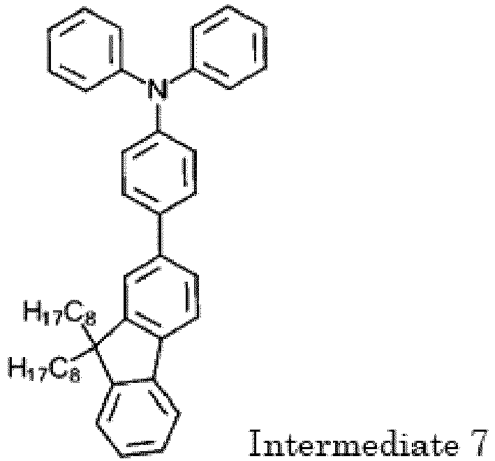
- The following components were placed in a reaction vessel whose internal air was replaced with nitrogen, and nitrogen gas was passed through the reaction vessel for 30 minutes:
- 20.0 g of 2-bromo-9,9-dioctylfluorene;
- 16.6 g of
N,N-diphenyl-4-(4,4,5,5-tetramethyl-1,3,2-dioxaborolane-2-yl)benzeneamine; - 28 ml of aqueous solution of 2M-potassium carbonate;
- 100 ml of toluene; and
- 25 ml of ethanol.
- Then, 1.0 g of tetrakis(triphenylphosphine)palladium(0) was added, and the mixture was heated and stirred under reflux for 6 hours. After the mixture was cooled down to room temperature, water and toluene were added, and a separation operation was performed to extract an organic layer. The organic layer was dehydrated using magnesium sulfate anhydrous, and then concentrated under reduced pressure to obtain a crude product. The crude product was purified through column chromatography (n-hexane), and 25.1 g (yield 93%) of a pale yellow oil of intermediate 7 was thereby obtained.
- <Synthesis of
Intermediate 8>
- The following components were placed in a reaction vessel whose internal air was replaced with nitrogen.
- 24.9 g of intermediate 7; and
- 150 ml of tetrahydrofuran.
- Then, at room temperature, 13.3 g of N-bromosuccinimide was added, and the mixture was stirred for 5 hours.
- Then, water and toluene were added, and a separation operation was performed to extract an organic layer. The organic layer was dehydrated using magnesium sulfate anhydrous, and then concentrated under reduced pressure, and 29.5 g (yield 95%) of an orange oil of intermediate 8 was thereby obtained.
-

- The following components were placed in a reaction vessel whose internal air was replaced with nitrogen, and nitrogen gas was passed through the reaction vessel for 30 minutes:
- 29.4 g of intermediate 8;
- 19.8 g of bis(pinacolato)diboron;
- 9.1 g of potassium acetate; and
- 200 ml of 1,4-dioxane.
- Then, 0.3 g of [1,1'-bis(diphenylphosphino)ferrocene]palladium (II)dichloride dichloromethane adduct was added, and the mixture was heated and stirred at 100°C for 10 hours. After the mixture was cooled down to room temperature, water and toluene were added, and a separation operation was performed to extract an organic layer. The organic layer was dehydrated using magnesium sulfate anhydrous, and then concentrated under reduced pressure to obtain a crude product. The crude product was purified through column chromatography (ethyl acetate / n-hexane = 1/20), and 8.0 g (yield 24%) of a white powder of intermediate 9 was thereby obtained.
- The following components were placed in a reaction vessel whose internal air was replaced with nitrogen, and nitrogen gas was passed through the reaction vessel for 30 minutes:
- 5.0 g of intermediate 1;
- 1.8 g of 1,3-dibromobenzene;
- 0.8 g of intermediate 2;
- 6.9 g of tripotassium phosphate;
- 9 ml of toluene;
- 5 ml of water; and
- 27 ml of 1,4-dioxane.
- Then, 1.4 mg of palladium(II) acetate and 11.5 mg of tri-o-tolylphosphine were added, and the mixture was heated and stirred at 87°C for 14 hours. Then, 17 mg of phenylboronic acid was added and the mixture was stirred for 1 hour, and then 242 mg of bromobenzene was added and the mixture was stirred for 1 hour. Then, 50 ml of toluene and 50 ml of 5 wt% aqueous solution of N,N-sodium diethyldithiocarbamate were added, and the mixture was heated and stirred under reflux for 2 hours. After the mixture was cooled down to room temperature, a separation operation was performed to extract an organic layer. The organic layer was washed three times with a saturated saline solution. The organic layer was dehydrated using magnesium sulfate anhydrous, and then concentrated under reduced pressure to obtain a crude polymer. The crude polymer was dissolved in toluene and adsorbed and purified by adding a silica gel, and then the silica gel was removed through filtering. The obtained filtrate was concentrated under reduced pressure, 100 ml of toluene was added to a dried solid to dissolve the dried solid, the resultant was dripped into 300 ml of n-hexane, and a precipitate was obtained through filtering. This operation was repeated three times, and the resultant was dried to obtain 3.5 g (yield 78%) of high molecular weight compound A.
- The average molecular weight measured using GPC and the degree of dispersion of the high molecular weight compound A were as follows.
- Number average molecular weight Mn (on polystyrene basis): 32,000
- Weight average molecular weight Mw (on polystyrene basis): 55,000
- Degree of dispersion (Mw/Mn): 1.7
- Furthermore, the high molecular weight compound A was subjected to NMR measurement.
Fig. 8 shows the result of 1H-NMR measurement. The chemical composition formula thereof was as follows.
- As can be understood from the chemical composition given above, the high molecular weight compound A contained 40 mol% of the structural unit A represented by the general formula (1), 50 mol% of the structural unit B represented by the general formula (2), and 10 mol% of thermal crosslinkable structural unit C.
- The following components were placed in a reaction vessel whose internal air was replaced with nitrogen, and nitrogen gas was passed through the reaction vessel for 30 minutes:
- 4.0 g of intermediate 1;
- 3.6 g of 1,4-dibromobenzene;
- 0.9 g of intermediate 2;
- 5.2 g of tripotassium phosphate;
- 7 ml of toluene;
- 4 ml of water; and
- 22 ml of 1,4-dioxane.
- Then, 1.1 mg of palladium(II) acetate and 8.7 mg of tri-o-tolylphosphine were added, and the mixture was heated and stirred at 83°C for 7.5 hours. Then, 17 mg of phenylboronic acid was added and the mixture was stirred for 1 hour, and then 196 mg of bromobenzene was added and the mixture was stirred for 1 hour. Then, 100 ml of toluene and 100 ml of 5 wt% aqueous solution of N,N-sodium diethyldithiocarbamate were added, and the mixture was heated and stirred under reflux for 2 hours. After the mixture was cooled down to room temperature, a separation operation was performed to extract an organic layer. The organic layer was washed three times with a saturated saline solution. The organic layer was dehydrated using magnesium sulfate anhydrous, and then concentrated under reduced pressure to obtain a crude polymer. The crude polymer was dissolved in toluene and adsorbed and purified by adding a silica gel, and then the silica gel was removed through filtering. The obtained filtrate was concentrated under reduced pressure, 120 ml of toluene was added to a dried solid to dissolve the dried solid, the resultant was dripped into 240 ml of n-hexane, and a precipitate was obtained through filtering. This operation was repeated twice, and the resultant was dried to obtain 3.1 g (yield 86%) of high molecular weight compound B.
- The average molecular weight measured using GPC and the degree of dispersion of the high molecular weight compound B were as follows.
- Number average molecular weight Mn (on polystyrene basis): 32,000
- Weight average molecular weight Mw (on polystyrene basis): 57,000
- Degree of dispersion (Mw/Mn): 1.8
- Furthermore, the high molecular weight compound B was subjected to NMR measurement.
Fig. 9 shows the result of 1H-NMR measurement. The chemical composition formula thereof was as follows.
- As can be understood from the chemical composition given above, the high molecular weight compound B contained 40 mol% of the structural unit A represented by the general formula (1), 50 mol% of the structural unit B represented by the general formula (2), and 10 mol% of thermal crosslinkable structural unit C.
- The following components were placed in a reaction vessel whose internal air was replaced with nitrogen, and nitrogen gas was passed through the reaction vessel for 30 minutes:
- 3.4 g of intermediate 1;
- 2.1 g of intermediate 3;
- 0.5 g of intermediate 2;
- 4.7 g of tripotassium phosphate;
- 7 ml of toluene;
- 4 ml of water; and
- 21 ml of 1,4-dioxane.
- Then, 5 mg of tetrakis(triphenylphosphine)palladium(0) was added, and the mixture was heated and stirred at 90°C for 19.5 hours. Then, 12 mg of phenylboronic acid was added and the mixture was stirred for 1 hour, and then 165 mg of bromobenzene was added and the mixture was stirred for 1 hour. Then, 50 ml of toluene and 50 ml of 5 wt% aqueous solution of N,N-sodium diethyldithiocarbamate were added, and the mixture was heated and stirred under reflux for 2 hours. After the mixture was cooled down to room temperature, a separation operation was performed to extract an organic layer. The organic layer was washed three times with a saturated saline solution. The organic layer was dehydrated using magnesium sulfate anhydrous, and then concentrated under reduced pressure to obtain a crude polymer. The crude polymer was dissolved in toluene and adsorbed and purified by adding a silica gel, and then the silica gel was removed through filtering. The obtained filtrate was concentrated under reduced pressure, 80 ml of toluene was added to a dried solid to dissolve the dried solid, the resultant was dripped into 240 ml of n-hexane, and a precipitate was obtained through filtering. This operation was repeated three times, and the resultant was dried to obtain 3.0 g (yield 80%) of high molecular weight compound C.
- The average molecular weight measured using GPC and the degree of dispersion of the high molecular weight compound C were as follows.
- Number average molecular weight Mn (on polystyrene basis): 35,000
- Weight average molecular weight Mw (on polystyrene basis): 69,000
- Degree of dispersion (Mw/Mn): 2.0
- Furthermore, the high molecular weight compound C was subjected to NMR measurement.
Fig. 10 shows the result of 1H-NMR measurement. The chemical composition formula thereof was as follows.

- As can be understood from the chemical composition given above, the high molecular weight compound C contained 40 mol% of the structural unit A represented by the general formula (1), 50 mol% of the structural unit B represented by the general formula (2), and 10 mol% of thermal crosslinkable structural unit C.
- The following components were placed in a reaction vessel whose internal air was replaced with nitrogen, and nitrogen gas was passed through the reaction vessel for 30 minutes:
- 5.0 g of intermediate 1;
- 1.8 g of 1,3-dibromobenzene;
- 0.7 g of intermediate 6;
- 6.9 g of tripotassium phosphate;
- 9 ml of toluene;
- 5 ml of water; and
- 27 ml of 1,4-dioxane.
- Then, 1.4 mg of palladium(II) acetate and 11.5 mg of tri-o-tolylphosphine were added, and the mixture was heated and stirred at 80°C for 14 hours. Then, 17 mg of phenylboronic acid was added and the mixture was stirred for 1 hour, and then 242 mg of bromobenzene was added and the mixture was stirred for 1 hour. Then, 100 ml of toluene and 50 ml of 5 wt% aqueous solution of N,N-sodium diethyldithiocarbamate were added, and the mixture was heated and stirred under reflux for 2 hours. After the mixture was cooled down to room temperature, a separation operation was performed to extract an organic layer. The organic layer was washed three times with a saturated saline solution. The organic layer was dehydrated using magnesium sulfate anhydrous, and then concentrated under reduced pressure to obtain a crude polymer. The crude polymer was dissolved in toluene and adsorbed and purified by adding a silica gel, and then the silica gel was removed through filtering. The obtained filtrate was concentrated under reduced pressure, 100 ml of toluene was added to a dried solid to dissolve the dried solid, the resultant was dripped into 300 ml of n-hexane, and a precipitate was obtained through filtering. This operation was repeated three times, and the resultant was dried to obtain 3.2 g (yield 73%) of high molecular weight compound D.
- The average molecular weight measured using GPC and the degree of dispersion of the high molecular weight compound D were as follows.
- Number average molecular weight Mn (on polystyrene basis): 44,000
- Weight average molecular weight Mw (on polystyrene basis): 71,000
- Degree of dispersion (Mw/Mn): 1.6
- Furthermore, the high molecular weight compound D was subjected to NMR measurement.
Fig. 11 shows the result of 1H-NMR measurement. The chemical composition formula thereof was as follows.
- As can be understood from the chemical composition given above, the high molecular weight compound D contained 40 mol% of the structural unit A represented by the general formula (1), 50 mol% of the structural unit B represented by the general formula (2), and 10 mol% of thermal crosslinkable structural unit C.
- The following components were placed in a reaction vessel whose internal air was replaced with nitrogen, and nitrogen gas was passed through the reaction vessel for 30 minutes:
- 5.0 g of intermediate 9;
- 1.7 g of 1,3-dibromobenzene;
- 0.7 g of intermediate 2;
- 6.3 g of tripotassium phosphate;
- 9 ml of toluene;
- 5 ml of water; and
- 27 ml of 1,4-dioxane.
- Then, 1.3 mg of palladium(II) acetate and 10.5 mg of tri-o-tolylphosphine were added, and the mixture was heated and stirred at 88°C for 11 hours. Then, 16 mg of phenylboronic acid was added and the mixture was stirred for 1 hour, and then 222 mg of bromobenzene was added and the mixture was stirred for 1 hour. Then, 50 ml of toluene and 50 ml of 5 wt% aqueous solution of N,N-sodium diethyldithiocarbamate were added, and the mixture was heated and stirred under reflux for 2 hours. After the mixture was cooled down to room temperature, a separation operation was performed to extract an organic layer. The organic layer was washed three times with a saturated saline solution. The organic layer was dehydrated using magnesium sulfate anhydrous, and then concentrated under reduced pressure to obtain a crude polymer. The crude polymer was dissolved in toluene and adsorbed and purified by adding a silica gel, and then the silica gel was removed through filtering. The obtained filtrate was concentrated under reduced pressure, 100 ml of toluene was added to a dried solid to dissolve the dried solid, the resultant was dripped into 100 ml of n-hexane, and a precipitate was obtained through filtering. This operation was repeated three times, and the resultant was dried to obtain 2.2 g (yield 48%) of high molecular weight compound E.
- The average molecular weight measured using GPC and the degree of dispersion of the high molecular weight compound E were as follows.
- Number average molecular weight Mn (on polystyrene basis): 55,000
- Weight average molecular weight Mw (on polystyrene basis): 93,000
- Degree of dispersion (Mw/Mn): 1.7
- Furthermore, the high molecular weight compound E was subjected to NMR measurement.
Fig. 12 shows the result of 1H-NMR measurement. The chemical composition formula thereof was as follows.
- As can be understood from the chemical composition given above, the high molecular weight compound E contained 40 mol% of the structural unit A represented by the general formula (1), 50 mol% of the structural unit B represented by the general formula (2), and 10 mol% of thermal crosslinkable structural unit C.
- The following components were placed in a reaction vessel whose internal air was replaced with nitrogen, and nitrogen gas was passed through the reaction vessel for 30 minutes:
- 5.0 g of intermediate 1;
- 1.8 g of 1,3-dibromobenzene;
- 0.8 g of
N-phenyl-4-(4,4,5,5-tetramethyl-1,3,2-dioxaborolane-2-yl)-N-[4-(4,4,5,5-tetramethyl-1,3, 2-dioxaborolane-2-yl)phenyl]benzeneamine; - 6.9 g of tripotassium phosphate;
- 9 ml of toluene;
- 5 ml of water; and
- 27 ml of 1,4-dioxane.
- Then, 1.4 mg of palladium(II) acetate and 11.5 mg of tri-o-tolylphosphine were added, and the mixture was heated and stirred at 86°C for 11.5 hours. Then, 17 mg of phenylboronic acid was added and the mixture was stirred for 1 hour, and then 242 mg of bromobenzene was added and the mixture was stirred for 1 hour. Then, 50 ml of toluene and 50 ml of 5 wt% aqueous solution of N,N-sodium diethyldithiocarbamate were added, and the mixture was heated and stirred under reflux for 2 hours. After the mixture was cooled down to room temperature, a separation operation was performed to extract an organic layer. The organic layer was washed three times with a saturated saline solution. The organic layer was dehydrated using magnesium sulfate anhydrous, and then concentrated under reduced pressure to obtain a crude polymer. The crude polymer was dissolved in toluene and adsorbed and purified by adding a silica gel, and then the silica gel was removed through filtering. The obtained filtrate was concentrated under reduced pressure, 100 ml of toluene was added to a dried solid to dissolve the dried solid, the resultant was dripped into 300 ml of n-hexane, and a precipitate was obtained through filtering. This operation was repeated three times, and the resultant was dried to obtain 3.4 g (yield 75%) of high molecular weight compound F.
- The average molecular weight measured using GPC and the degree of dispersion of the high molecular weight compound F were as follows.
- Number average molecular weight Mn (on polystyrene basis): 32,000
- Weight average molecular weight Mw (on polystyrene basis): 54,000
- Degree of dispersion (Mw/Mn): 1.7
- Furthermore, the high molecular weight compound F was subjected to NMR measurement.
Fig. 13 shows the result of 1H-NMR measurement. The chemical composition formula thereof was as follows.
- As can be understood from the chemical composition given above, the high molecular weight compound F contained 40 mol% of the structural unit A represented by the general formula (1), 50 mol% of the structural unit B represented by the general formula (2), and 10 mol% of the triarylamine structural unit D that is different from that represented by the general formula (1).
- Coating films each having a thickness of 80 nm were formed on an ITO substrate using the high molecular weight compounds A to F synthesized in Examples 1 to 6, and the work function was measured using an ionization potential measurement apparatus (Model PYS-202 available from Sumitomo Heavy Industries, Ltd.). The result was as follows.
Table 1 Work function (eV) Example 1 High molecular weight compound A 5.66 Example 2 High molecular weight compound B 5.48 Example 3 High molecular weight compound C 5.73 Example 4 High molecular weight compound D 5.64 Example 5 High molecular weight compound E 5.68 Example 6 High molecular weight compound F 5.64 - The high molecular weight compounds A to F according to the present invention exhibited a preferable energy level higher than 5.4 eV that is the work function of ordinary hole transport materials such as NPD and TPD, from which it can be seen that the high molecular weight compounds A to F have good hole transport capability.
- An organic EL element having a layer structure shown in
Fig. 6 was produced in the following manner. - Specifically, a
glass substrate 1 on which an ITO film having a thickness of 50 nm was formed was washed with an organic solvent, and then UV/ozone treatment was performed to wash the surface of the ITO film. A PEDOT/PSS (available from HERAEUS) was applied using a spin coating method so as to cover the transparent anode 2 (ITO) formed on theglass substrate 1, and a 50 nm thick film was thereby formed. The film was dried on a hot plate at 200°C for 10 minutes, and ahole injection layer 3 was thereby formed. - A coating solution was prepared by dissolving the high molecular weight compound A obtained in Example 1 in toluene at a concentration of 0.6 wt%. The substrate on which the
hole injection layer 3 was formed in the manner described above was placed in a glove box whose internal air was replaced with dry nitrogen, and a coating layer having a thickness of 25 nm was formed on thehole injection layer 3 through spin coating using the coating solution described above, and dried on a hot plate at 200°C for 10 minutes, and ahole transport layer 4 was thereby formed. - The substrate on which the
hole transport layer 4 was formed in the manner described above was set in a vacuum deposition apparatus, and the pressure was reduced to 0.001 Pa or less. Alight emitting layer 5 having a thickness of 34 nm was formed on thehole transport layer 4 through dual deposition using a blue light emitting material (EMD-1) and a host material (EMH-1) represented by the structure formulae below. In the dual deposition, the ratio of deposition rate was set to EMD-1 : EMH-1 = 4 : 96.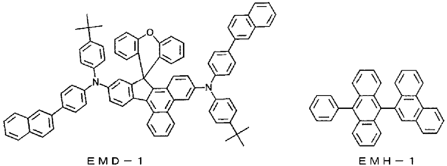
- Compounds ETM-1 and ETM-2 represented by the following structural formulae were prepared as the electron transport materials.

- An
electron transport layer 6 having a thickness of 20 nm was formed on thelight emitting layer 5 formed above through dual deposition using the electron transport materials ETM-1 and ETM-2. - In the dual deposition, the ratio of deposition rate was set to ETM-1 : ETM-2 = 50 : 50.
- Finally, aluminum was deposited so as to form a film having a thickness of 100 nm, and a
cathode 7 was thereby formed. - The glass substrate on which the
transparent anode 2, thehole injection layer 3, thehole transport layer 4, thelight emitting layer 5, theelectron transport layer 6, and thecathode 7 were formed, was placed in a glove box whose internal air was replaced with dry nitrogen, and another glass substrate for sealing was bonded using a UV curable resin, and an organic EL element was thereby produced. The characteristics of the produced organic EL element were measured in an atmosphere at room temperature. - Also, light emission characteristics when applying a DC voltage to the produced organic EL element were measured.
- The measurement results are shown in Table 2.
- An organic EL element was produced as in Example 8, except that the
hole transport layer 4 was formed using a coating solution prepared by dissolving, instead of the high molecular weight compound A, the compound (the high molecular weight compound B) of Example 2 in toluene at a concentration of 0.6 wt%. The characteristics of the produced organic EL element were measured in an atmosphere at room temperature. The measurement results of light emission characteristics as measured while applying a DC voltage to the produced organic EL element are shown in Table 2. - An organic EL element was produced as in Example 8, except that the
hole transport layer 4 was formed using a coating solution prepared by dissolving, instead of the high molecular weight compound A, the compound (the high molecular weight compound C) of Example 3 in toluene at a concentration of 0.6 wt%. The characteristics of the produced organic EL element were measured in an atmosphere at room temperature. The measurement results of light emission characteristics as measured while applying a DC voltage to the produced organic EL element are shown in Table 2. - An organic EL element was produced as in Example 8, except that the
hole transport layer 4 was formed using a coating solution prepared by dissolving, instead of the high molecular weight compound A, the compound (the high molecular weight compound D) of Example 4 in toluene at a concentration of 0.6 wt%. The characteristics of the produced organic EL element were measured in an atmosphere at room temperature. The measurement results of light emission characteristics as measured while applying a DC voltage to the produced organic EL element are shown in Table 2. - An organic EL element was produced as in Example 8, except that the
hole transport layer 4 was formed using a coating solution prepared by dissolving, instead of the high molecular weight compound A, the compound (the high molecular weight compound E) of Example 5 in toluene at a concentration of 0.6 wt%. The characteristics of the produced organic EL element were measured in an atmosphere at room temperature. The measurement results of light emission characteristics as measured while applying a DC voltage to the produced organic EL element are shown in Table 2. - An organic EL element was produced as in Example 8, except that the
hole transport layer 4 was formed using a coating solution prepared by dissolving, instead of the high molecular weight compound A, the compound (the high molecular weight compound F) of Example 6 in toluene at a concentration of 0.6 wt%. The characteristics of the produced organic EL element were measured in an atmosphere at room temperature. The measurement results of light emission characteristics as measured while applying a DC voltage to the produced organic EL element are shown in Table 2. - An organic EL element was produced as in Example 8, except that the
hole transport layer 4 was formed using a coating solution prepared by dissolving, instead of the high molecular weight compound A, TFB (hole transport polymer) shown below in toluene at a concentration of 0.6 wt%.
- TFB (hole transport polymer) is poly[(9,9-dioctylfluorenyl-2,7-diyl)-co-(4,4'-(N-(4-sec-butylphenyl))diphenylamine] (Hole Transport Polymer ADS259BE available from American Dye Source). Various characteristics of the organic EL element of Comparative Example 1 were evaluated as in Example 8. The results are shown in Table 2.
- In the evaluation of various characteristics, element lifespan is defined as the time taken for light emission luminance to decay from 700 cd/m2 , the light emission luminance being set to when light emission starts (initial luminance), to 560 cd/m2 (corresponding to 80% of the initial luminance being set to 100%: at a decay of 80%) when constant current driving is performed.
Table 2 High molecular weight compound Voltage [V] (@ 10 mA/cm2) Luminance [cd/m2] (@ 10 mA/cm2) Light emission efficiency [cd/A] (@ 10 mA/cm2) Power efficiency [1m/W] (@ 10 mA/cm2) Element lifespan at decay of 80% 700 cd/m2) Example 8 A 4.25 904 9.03 6.69 190 hours Example 9 B 4.00 737 7.37 5.79 115 hours Example 10 C 4.48 956 9.58 6.72 83 hours Example 11 D 4.07 702 7.01 5.41 409 hours Example 12 E 4.18 780 7.80 5.87 264 hours Example 13 F 4.09 883 8.82 6.46 29 hours Comparative Example 1 TFB 3.89 552 5.53 4.47 7 hours - As shown in Table 2, the light emission efficiency at an electric current density of 10 mA/cm2 was 9.03 cd/A in the organic EL element of Example 8, 7.37 cd/A in the organic EL element of Example 9, 9.58 cd/A in the organic EL element of Example 10, 7.01 cd/A in the organic EL element of Example 11, 7.80 cd/A in the organic EL element of Example 12, and 8.82 cd/A in the organic EL element of Example 13, relative to 5.53 cd/A in the organic EL element of Comparative Example 1. That is, all of the organic EL elements of these examples exhibited high efficiency. Also, the element lifespan (at a decay of 80%) was 190 hours in the organic EL element of Example 8, 115 hours in the organic EL element of Example 9, 83 hours in the organic EL element of Example 10, 409 hours in the organic EL element of Example 11, 264 hours in the organic EL element of Example 12, and 29 hours in the organic EL element of Example 13, relative to 7 hours in the organic EL element of Comparative Example 1. That is, all of the organic EL elements of these examples exhibited a long lifespan.
- An organic EL element having a layer structure shown in
Fig. 7 was produced in the following manner. - Specifically, a
glass substrate 8 on which an ITO film having a thickness of 50 nm was formed was washed with an organic solvent, and then UV/ozone treatment was performed to wash the surface of the ITO film. A PEDOT/PSS (available from HERAEUS) was applied using a spin coating method so as to cover the transparent anode 9 (ITO) formed on theglass substrate 8, and a 50 nm thick film was thereby formed. The film was dried on a hot plate at 200°C for 10 minutes, and ahole injection layer 10 was thereby formed. - A coating solution was prepared by dissolving a high molecular weight compound HTM-1 represented by the structure formula below in toluene at a concentration of 0.6 wt%. The substrate on which the
hole injection layer 10 was formed in the manner described above was placed in a glove box whose internal air was replaced with dry nitrogen, and a coating layer having a thickness of 25 nm was formed on thehole injection layer 10 through spin coating using the coating solution described above, and dried on a hot plate at 200°C for 30 minutes, and ahole transport layer 11 was thereby formed.
- A coating solution was prepared by dissolving the high molecular weight compound A obtained in Example 1 in toluene at a concentration of 0.6 wt%. A coating layer having a thickness of 15 nm was formed on the
hole transport layer 11 through spin coating using the coating solution described above, and dried on a hot plate at 200°C for 10 minutes, and anelectron blocking layer 12 was thereby formed. - The substrate on which the
electron blocking layer 12 was formed in the manner described above was set in a vacuum deposition apparatus, and the pressure was reduced to 0.001 Pa or less. Alight emitting layer 13 having a thickness of 34 nm was formed on theelectron blocking layer 12 through dual deposition using a blue light emitting material (EMD-1) and a host material (EMH-1). In the dual deposition, the ratio of deposition rate was set to EMD-1 : EMH-1 = 4 : 96. - An
electron transport layer 14 having a thickness of 20 nm was formed on thelight emitting layer 13 formed above through dual deposition using the electron transport materials ETM-1 and ETM-2. In the dual deposition, the ratio of deposition rate was set to ETM-1: ETM-2 = 50 : 50. - Finally, aluminum was deposited so as to form a film having a thickness of 100 nm, and a
cathode 15 was thereby formed. - The glass substrate on which the
transparent anode 9, thehole injection layer 10, thehole transport layer 11, theelectron blocking layer 12, thelight emitting layer 13, theelectron transport layer 14, and thecathode 15 were formed was placed in a glove box whose internal air was replaced with dry nitrogen, and another glass substrate for sealing was bonded using a UV curable resin, and an organic EL element was thereby produced. The characteristics of the produced organic EL element were measured in an atmosphere at room temperature. Also, light emission characteristics when applying a DC voltage to the produced organic EL element were measured. The measurement results are shown in Table 3. - An organic EL element having a layer structure shown in
Fig. 6 was produced in the following manner. - Specifically, a
glass substrate 1 on which an ITO film having a thickness of 50 nm was formed was washed with an organic solvent, and then UV/ozone treatment was performed to wash the surface of the ITO film. A PEDOT/PSS (available from HERAEUS) was applied using a spin coating method so as to cover the transparent anode 2 (ITO) formed on theglass substrate 1, and a 50 nm thick film was thereby formed. The film was dried on a hot plate at 200°C for 10 minutes, and ahole injection layer 3 was thereby formed. - A coating solution was prepared by dissolving the high molecular weight compound HTM-1 in toluene at a concentration of 0.6 wt%. The substrate on which the
hole injection layer 3 was formed in the manner described above was placed in a glove box whose internal air was replaced with dry nitrogen, and a coating layer having a thickness of 25 nm was formed on thehole injection layer 3 through spin coating using the coating solution described above, and dried on a hot plate at 200°C for 10 minutes, and ahole transport layer 4 was thereby formed. - The substrate on which the
hole transport layer 4 was formed in the manner described above was set in a vacuum deposition apparatus, and the pressure was reduced to 0.001 Pa or less. Alight emitting layer 5 having a thickness of 40 nm was formed on thehole transport layer 4 through dual deposition using a blue light emitting material (EMD-1) and a host material (EMH-1). In the dual deposition, the ratio of deposition rate was set to EMD-1 : EMH-1 = 4 : 96. - An
electron transport layer 6 having a thickness of 20 nm was formed on thelight emitting layer 5 formed above through dual deposition using the electron transport materials (ETM-1) and (ETM-2). In the dual deposition, the ratio of deposition rate was set to ETM-1 : ETM-2 = 50 : 50. - Finally, aluminum was deposited so as to form a film having a thickness of 100 nm, and a
cathode 7 was thereby formed. - The glass substrate on which the
transparent anode 2, thehole injection layer 3, thehole transport layer 4, thelight emitting layer 5, theelectron transport layer 6, and thecathode 7 were formed was placed in a glove box whose internal air was replaced with dry nitrogen, and another glass substrate for sealing was bonded using a UV curable resin, and an organic EL element was thereby produced. The characteristics of the produced organic EL element were measured in an atmosphere at room temperature. Also, light emission characteristics when applying a DC voltage to the produced organic EL element were measured. The measurement results are shown in Table 3. - In the evaluation of various characteristics, element lifespan is defined as the time taken for light emission luminance to decay from 700 cd/m2, the light emission luminance (initial luminance) being set to when light emission starts, to 630 cd/m2 (corresponding to 90% of the initial luminance being set to 100%: at a decay of 90%) when constant current driving is performed.
Table 3 Electron blocking layer Voltage [V] (@ 10 mA/cm2) Luminance [cd/m2] (@ 10 mA/cm2) Light emission efficiency [cd/A] (@ 10 mA/cm2) Power efficiency [1m/W] (@ 10 mA/cm2) Element lifespan at decay of 90% (@ 700 cd/m2) Example 14 High molecular weight compound A 4.10 930 9.29 7.12 153 hours Comparative Example 2 None 3.93 826 8.26 6.60 55 hours - As shown in Table 3, the light emission efficiency at an electric current density of 10 mA/cm2 was 9.29 cd/A in the organic EL element of Example 14 relative to 8.26 cd/A in the organic EL element of Comparative Example 2. That is, the organic EL element of the example exhibited high efficiency. Also, the element lifespan (at a decay of 90%) was 153 hours in the organic EL element of Example 14 relative to 55 hours in the organic EL element of Comparative Example 2. That is, the organic EL element of the example exhibited a long lifespan.
- As can be seen from the foregoing, an organic EL element including an organic layer formed using the high molecular weight compound according to the present invention can have higher light emission efficiency and a longer lifespan as compared with a conventional organic EL element.
- A thin film was formed on a glass substrate through spin coating using a solution prepared by dissolving the high molecular weight compound A synthesized in Example 1 in toluene at a concentration of 0.6 wt%. The obtained film was placed in a glove box whose internal air was replaced with dry nitrogen, and baked on a hot plate at 200°C for 60 minutes or 230°C for 10 minutes. After the baked film was cooled down to room temperature, absorption intensity of light at a wavelength of 300 to 700 nm was measured using a spectrophotometer (U-3000 available from Hitachi, Ltd.). Also, the film that has undergone absorption intensity measurement was rinsed with toluene using a spin coater at 2000 rpm for 15 seconds. The absorption intensity of the rinsed film was measured using the spectrophotometer.
- Residual film ratio was calculated, using the following equation, from the absorption intensity values before and after rinsing measured in the manner described above. The results are shown in Table 4.

- where α represents the absorption intensity (peak top) after rinsing, and
- β represents the absorption intensity (peak top) before rinsing.
- The residual film ratio was calculated as in Example 15, except that the high molecular weight compound A was changed to the high molecular weight compound B synthesized in Example 2. The result is shown in Table 4.
- The residual film ratio was calculated as in Example 15, except that the high molecular weight compound A was changed to the high molecular weight compound C synthesized in Example 3. The result is shown in Table 4.
- The residual film ratio was calculated as in Example 15, except that the high molecular weight compound A was changed to the high molecular weight compound D synthesized in Example 4. The result is shown in Table 4.
- The residual film ratio was calculated as in Example 15, except that the high molecular weight compound A was changed to the high molecular weight compound E synthesized in Example 5. The result is shown in Table 4.
- The residual film ratio was calculated as in Example 15, except that the high molecular weight compound A was changed to TFB used in Comparative Example 1. The result is shown in Table 4.
Table 4 High molecular weight compound Residual film ratio Baked at 200°C/60 min Baked at 230°C/10 min Example 15 A 96.3% 100% Example 16 B 90.5% 100% Example 17 C 88.9% 96.7% Example 18 D 94.7% 100% Example 19 E 100% 100% Comparative Example 3 TFB 28.9% 33.6% - As shown in Table 4, the high molecular weight compound A exhibited a residual film ratio of 96.3% when baked at 200°C for 60 minutes and 100% when baked at 230°C for 10 minutes, the high molecular weight compound B exhibited a residual film ratio of 90.5% when baked at 200°C for 60 minutes and 100% when baked at 230°C for 10 minutes, the high molecular weight compound C exhibited a residual film ratio of 88.9% when baked at 200°C for 60 minutes and 96.7% when baked at 230°C for 10 minutes, the high molecular weight compound D exhibited a residual film ratio of 94.7% when baked at 200°C for 60 minutes and 100% when baked at 230°C for 10 minutes, and the high molecular weight compound E exhibited a residual film ratio of 100% when baked both at 200°C for 60 minutes and 230°C for 10 minutes. That is, all of the organic EL elements of these examples exhibited high residual film ratio. That is, it is seen that the high molecular weight compounds according to the present invention has a high level of curability (thermal crosslinkability).
- The high molecular weight compound according to the present invention has high hole transport capability, excellent electron blocking capability, and good thermal crosslinkability. Accordingly, the high molecular weight compound according to the present invention is usable as a compound for producing coating type organic EL elements. By producing coating type organic EL elements using the compound, it is possible to obtain high light emission efficiency and high power efficiency, and also possible to improve durability. Accordingly, for example, the coating type organic EL elements can be used in a wide range of applications such as home electric appliances and lighting equipment.
-
- 1, 8
- Glass substrate
- 2, 9
- Transparent anode
- 3, 10
- Hole injection layer
- 4, 11
- Hole transport layer
- 5, 13
- Light emitting layer
- 6, 14
- Electron transport layer
- 7, 15
- Cathode
- 12
- Electron blocking layer
Claims (13)
- A high molecular weight compound comprising a repeating unit represented by a general formula (3) below, that is constituted by a triarylamine structural unit represented by a general formula (1) below and a bonding structural unit represented by a general formula (2) below, and having a weight average molecular weight of 10,000 or more and less than 1,000,000 on a polystyrene basis,


 where R1 each independently represents a hydrogen atom, a heavy hydrogen atom, a cyano group, a nitro group, a fluorine atom, a chlorine atom, a bromine atom, an iodine atom, an alkyl group or an alkyloxy group with 1 to 8 carbon atoms, a cycloalkyl group or a cycloalkyloxy group with 5 to 10 carbon atoms, an alkenyl group with 2 to 6 carbon atoms, or an aryloxy group,R2 each independently represents an alkyl group or an alkyloxy group with 1 to 8 carbon atoms, or a cycloalkyl group or a cycloalkyloxy group with 5 to 10 carbon atoms,X represents a hydrogen atom, an amino group, a monovalent aryl group, or a monovalent heteroaryl group,L represents a divalent phenyl group, and n represents an integer of 0 to 3, anda represents an integer of 0 to 3, and b represents an integer of 0 to 4.
 - The high molecular weight compound as set forth in claim 1, wherein R1 is a hydrogen atom.
- The high molecular weight compound as set forth in claim 1 or 2, wherein R2 is an alkyl group with 1 to 8 carbon atoms.
- The high molecular weight compound as set forth in any one of claims 1 to 3, wherein X is a hydrogen atom.
- The high molecular weight compound as set forth in any one of claims 1 to 3, wherein X is a diphenylamino group, a phenyl group, a naphthyl group, a dibenzofuranyl group, a dibenzothienyl group, a phenanthrenyl group, a fluorenyl group, a carbazolyl group, an indenocarbazolyl group, or an acridinyl group.
- The high molecular weight compound as set forth in any one of claims 1 to 5, further comprising a repeating unit which is constituted by a thermal crosslinkable structural unit and the bonding structural unit represented by the general formula (2) above.
- The high molecular weight compound as set forth in claim 6, wherein the thermal crosslinkable structural unit is a structural unit represented by general formulae (4a) to (4z) below,

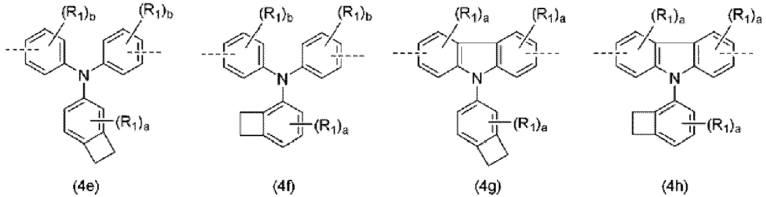


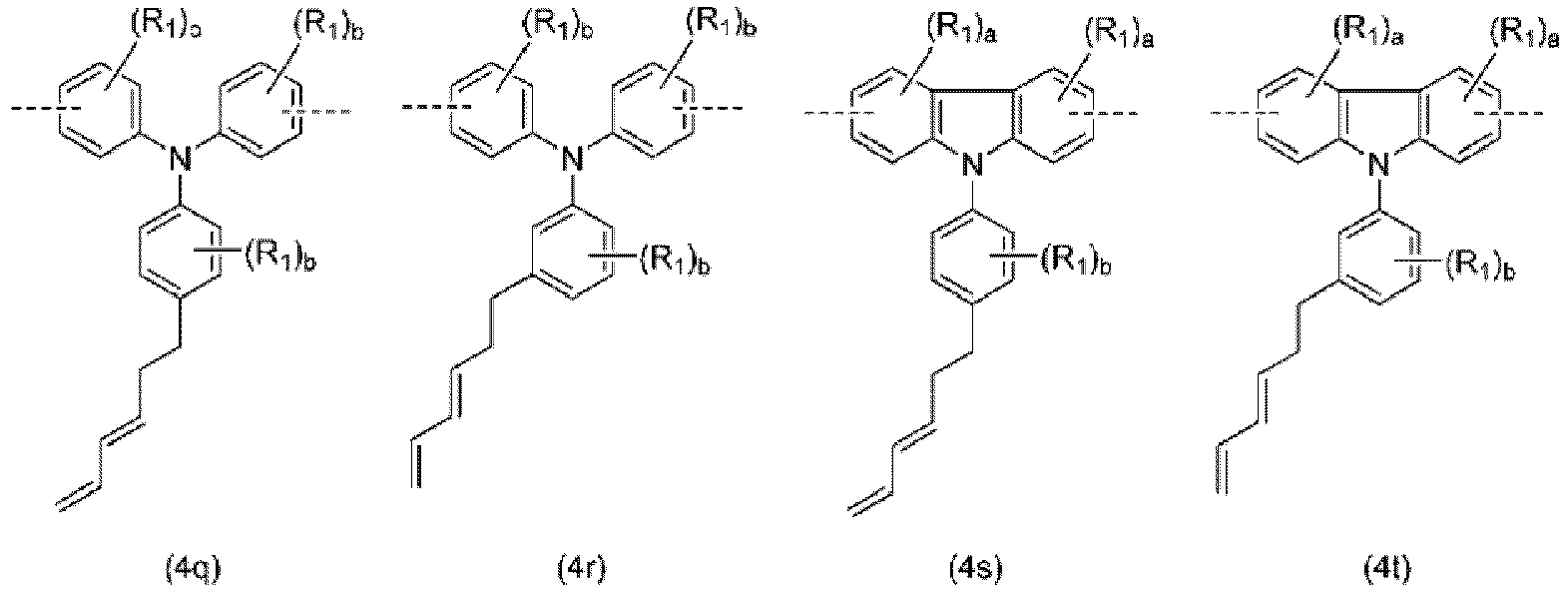


- The high molecular weight compound as set forth in any one of claims 1 to 5, further comprising a repeating unit which is constituted by a triarylamine structural unit that is different from those represented by the general formula (1) above and the bonding structural unit represented by the general formula (2) above.
- An organic electroluminescent element having a pair of electrodes and at least one organic layer interposed therebetween, the at least one organic layer containing the high molecular weight compound as set forth in any one of claims 1 to 8 as a constituent material.
- The organic electroluminescent element as set forth in claim 9, wherein the organic layer is a hole transport layer.
- The organic electroluminescent element as set forth in claim 9, wherein the organic layer is an electron blocking layer.
- The organic electroluminescent element as set forth in claim 9, wherein the organic layer is a hole injection layer.
- The organic electroluminescent element as set forth in claim 9, wherein the organic layer is a light emitting layer.
Applications Claiming Priority (2)
| Application Number | Priority Date | Filing Date | Title |
|---|---|---|---|
| JP2018126980 | 2018-07-03 | ||
| PCT/JP2019/026149 WO2020009069A1 (en) | 2018-07-03 | 2019-07-01 | High molecular weight triarylamine compound comprising terphenyl structure in molecular main chain and organic electroluminescent element comprising said high molecular weight compound |
Publications (2)
| Publication Number | Publication Date |
|---|---|
| EP3819325A1 true EP3819325A1 (en) | 2021-05-12 |
| EP3819325A4 EP3819325A4 (en) | 2022-05-11 |
Family
ID=69060360
Family Applications (1)
| Application Number | Title | Priority Date | Filing Date |
|---|---|---|---|
| EP19830414.9A Withdrawn EP3819325A4 (en) | 2018-07-03 | 2019-07-01 | HIGH MOLECULAR WEIGHT TRIARYLAMINE COMPOUND COMPRISING A TERPHENYL STRUCTURE IN A MAIN MOLECULAR CHAIN AND ORGANIC ELECTROLUMINESCENT ELEMENT COMPRISING SUCH HIGH MOLECULAR WEIGHT COMPOUND |
Country Status (7)
| Country | Link |
|---|---|
| US (1) | US11999818B2 (en) |
| EP (1) | EP3819325A4 (en) |
| JP (1) | JP7421476B2 (en) |
| KR (1) | KR102779388B1 (en) |
| CN (1) | CN112384547B (en) |
| TW (1) | TWI863916B (en) |
| WO (1) | WO2020009069A1 (en) |
Cited By (1)
| Publication number | Priority date | Publication date | Assignee | Title |
|---|---|---|---|---|
| EP4108701A4 (en) * | 2020-02-20 | 2024-03-06 | Hodogaya Chemical Co., Ltd. | High molecular weight compound and light emitting diode including said high molecular weight compound |
Families Citing this family (9)
| Publication number | Priority date | Publication date | Assignee | Title |
|---|---|---|---|---|
| JP7318233B2 (en) * | 2019-03-04 | 2023-08-01 | 株式会社レゾナック | Organic electronic materials and their uses |
| CN114375510B (en) | 2019-10-09 | 2024-05-21 | 保土谷化学工业株式会社 | Organic electroluminescent element having an organic layer containing a high molecular weight compound |
| JP7594870B2 (en) * | 2019-10-15 | 2024-12-05 | 住友化学株式会社 | Composition and light-emitting device containing same |
| CN114106295B (en) * | 2020-12-29 | 2023-06-16 | 广东聚华印刷显示技术有限公司 | Crosslinkable polymer, preparation method and application thereof |
| CN114031752B (en) * | 2020-12-29 | 2023-06-16 | 广东聚华印刷显示技术有限公司 | Polymeric crosslinkable compounds, process for their preparation and their use |
| CN117295779A (en) * | 2021-05-21 | 2023-12-26 | 保土谷化学工业株式会社 | Triarylamine high molecular weight compound and organic electroluminescent element containing the high molecular weight compound |
| EP4141041B1 (en) | 2021-08-31 | 2026-04-22 | Samsung Electronics Co., Ltd. | A polymer, a composition, and an electroluminescence device |
| CN118265737A (en) * | 2022-03-04 | 2024-06-28 | 保土谷化学工业株式会社 | Triarylamine high molecular weight compound and organic electroluminescent element |
| WO2023182377A1 (en) * | 2022-03-25 | 2023-09-28 | 保土谷化学工業株式会社 | High-molecular-weight triarylamine compound and organic electroluminescent element |
Family Cites Families (25)
| Publication number | Priority date | Publication date | Assignee | Title |
|---|---|---|---|---|
| US6309763B1 (en) | 1997-05-21 | 2001-10-30 | The Dow Chemical Company | Fluorene-containing polymers and electroluminescent devices therefrom |
| GB0028867D0 (en) | 2000-11-28 | 2001-01-10 | Avecia Ltd | Field effect translators,methods for the manufacture thereof and materials therefor |
| US7651746B2 (en) | 2003-11-14 | 2010-01-26 | Sumitomo Chemical Company, Limited | Halogenated bisdiarylaminopolycyclic aromatic compounds and polymers thereof |
| GB0329364D0 (en) | 2003-12-19 | 2004-01-21 | Cambridge Display Tech Ltd | Optical device |
| US20080274303A1 (en) | 2004-02-26 | 2008-11-06 | Katsumi Agata | Polymer Compound and Polymer Light Emitting Device Using the Same |
| JP2007119763A (en) | 2005-09-29 | 2007-05-17 | Sumitomo Chemical Co Ltd | Polymer material and polymer light emitting device |
| JP2007162008A (en) * | 2005-11-16 | 2007-06-28 | Tokyo Institute Of Technology | Polymer compound and polymer light emitting device |
| US20100176377A1 (en) | 2005-11-18 | 2010-07-15 | Sumitomo Chemical Company, Limited | Polymeric compound and polymeric electroluminescence element using the same |
| JP5018043B2 (en) | 2005-12-01 | 2012-09-05 | 住友化学株式会社 | Polymer compound and polymer light emitting device using the same |
| KR101323557B1 (en) * | 2008-02-15 | 2013-10-29 | 미쓰비시 가가꾸 가부시키가이샤 | Conjugated polymer, insolubilized polymer, organic electroluminescent device material, composition for organic electroluminescent device, method for producing polymer, organic electroluminescent device, organic el display, and organic el illuminator |
| KR101497754B1 (en) * | 2008-03-05 | 2015-03-02 | 이데미쓰 고산 가부시키가이샤 | Polymer and organic electroluminescent device including the same |
| JP2010062442A (en) * | 2008-09-05 | 2010-03-18 | Canon Inc | Organic light emitting element |
| JP5343832B2 (en) | 2008-12-04 | 2013-11-13 | 三菱化学株式会社 | Arylamine polymer, organic electroluminescent element material, composition for organic electroluminescent element, organic electroluminescent element, organic EL display and organic EL lighting |
| CN102598343B (en) * | 2009-10-23 | 2015-07-08 | 保土谷化学工业株式会社 | Organic electroluminescent element |
| DE102010007938A1 (en) | 2010-02-12 | 2011-10-06 | Merck Patent Gmbh | Electroluminescent polymers, process for their preparation and their use |
| JP5549879B2 (en) | 2010-10-25 | 2014-07-16 | 東ソー株式会社 | Random copolymer |
| GB201107905D0 (en) | 2011-05-12 | 2011-06-22 | Cambridge Display Tech Ltd | Light-emitting material, composition and device |
| EP2684932B8 (en) | 2012-07-09 | 2016-12-21 | Hodogaya Chemical Co., Ltd. | Diarylamino matrix material doped with a mesomeric radialene compound |
| WO2014038417A1 (en) * | 2012-09-07 | 2014-03-13 | 保土谷化学工業株式会社 | Novel benzothienoindole derivative and organic electroluminescent element in which novel benzothienoindole derivative is used |
| GB2524747B (en) | 2014-03-31 | 2017-03-01 | Cambridge Display Tech Ltd | Amine/fluorene copolymers and organic electronic devices comprising said copolymers |
| CN106795277B (en) | 2014-08-28 | 2020-04-10 | 住友化学株式会社 | Polymer compound and light-emitting element using same |
| KR102381180B1 (en) * | 2016-09-29 | 2022-04-01 | 스미또모 가가꾸 가부시키가이샤 | Light-emitting devices and compositions useful for manufacturing the light-emitting devices |
| JP6822363B2 (en) | 2016-09-29 | 2021-01-27 | 住友化学株式会社 | Light emitting element |
| JP6848787B2 (en) | 2016-09-29 | 2021-03-24 | 住友化学株式会社 | Light emitting element |
| WO2018101331A1 (en) * | 2016-11-30 | 2018-06-07 | 保土谷化学工業株式会社 | High molecular weight compound containing substituted triarylamine structural unit |
-
2019
- 2019-07-01 WO PCT/JP2019/026149 patent/WO2020009069A1/en not_active Ceased
- 2019-07-01 EP EP19830414.9A patent/EP3819325A4/en not_active Withdrawn
- 2019-07-01 CN CN201980038050.XA patent/CN112384547B/en active Active
- 2019-07-01 JP JP2020528985A patent/JP7421476B2/en active Active
- 2019-07-01 US US16/972,672 patent/US11999818B2/en active Active
- 2019-07-01 KR KR1020207033265A patent/KR102779388B1/en active Active
- 2019-07-02 TW TW108123274A patent/TWI863916B/en active
Cited By (1)
| Publication number | Priority date | Publication date | Assignee | Title |
|---|---|---|---|---|
| EP4108701A4 (en) * | 2020-02-20 | 2024-03-06 | Hodogaya Chemical Co., Ltd. | High molecular weight compound and light emitting diode including said high molecular weight compound |
Also Published As
| Publication number | Publication date |
|---|---|
| KR20210027250A (en) | 2021-03-10 |
| TWI863916B (en) | 2024-12-01 |
| KR102779388B1 (en) | 2025-03-10 |
| TW202006014A (en) | 2020-02-01 |
| CN112384547A (en) | 2021-02-19 |
| US11999818B2 (en) | 2024-06-04 |
| JP7421476B2 (en) | 2024-01-24 |
| US20210253785A1 (en) | 2021-08-19 |
| JPWO2020009069A1 (en) | 2021-08-02 |
| WO2020009069A1 (en) | 2020-01-09 |
| CN112384547B (en) | 2023-07-11 |
| EP3819325A4 (en) | 2022-05-11 |
Similar Documents
| Publication | Publication Date | Title |
|---|---|---|
| US11999818B2 (en) | High molecular weight triarylamine compound comprising terphenyl structure in molecular main chain and organic electroluminescent element comprising said high molecular weight compound | |
| EP3597689B1 (en) | High-molecular-weight compound having substituted triarylamine skeleton | |
| EP3549970B1 (en) | High molecular weight compound containing substituted triarylamine structural unit | |
| EP3981820A1 (en) | High-molecular-weight compound including substituted triarylamine structural unit, and organic electroluminescent device | |
| EP4043512A1 (en) | Organic electroluminescence element having organic layer comprising high molecular weight compound | |
| US20240260288A1 (en) | High molecular weight triarylamine compounds, and organic electroluminescent elements containing these high molecular weight compounds | |
| EP4108701A1 (en) | High molecular weight compound and light emitting diode including said high molecular weight compound | |
| KR20240138997A (en) | High molecular weight compound and organic electroluminescence device | |
| JP7783251B2 (en) | High molecular weight compounds having an indenodibenzoheterole structure as a partial structure, and organic electroluminescent devices containing these high molecular weight compounds | |
| KR20240007066A (en) | High molecular weight compound and organic electroluminescent device using same | |
| EP4219586A1 (en) | Thermally-crosslinkable low molecular weight compound-containing composition for light emitting diode | |
| KR20240155182A (en) | Triarylamine high molecular weight compounds and organic electroluminescent devices | |
| WO2023182377A1 (en) | High-molecular-weight triarylamine compound and organic electroluminescent element |
Legal Events
| Date | Code | Title | Description |
|---|---|---|---|
| STAA | Information on the status of an ep patent application or granted ep patent |
Free format text: STATUS: THE INTERNATIONAL PUBLICATION HAS BEEN MADE |
|
| PUAI | Public reference made under article 153(3) epc to a published international application that has entered the european phase |
Free format text: ORIGINAL CODE: 0009012 |
|
| STAA | Information on the status of an ep patent application or granted ep patent |
Free format text: STATUS: REQUEST FOR EXAMINATION WAS MADE |
|
| 17P | Request for examination filed |
Effective date: 20201124 |
|
| AK | Designated contracting states |
Kind code of ref document: A1 Designated state(s): AL AT BE BG CH CY CZ DE DK EE ES FI FR GB GR HR HU IE IS IT LI LT LU LV MC MK MT NL NO PL PT RO RS SE SI SK SM TR |
|
| DAV | Request for validation of the european patent (deleted) | ||
| DAX | Request for extension of the european patent (deleted) | ||
| A4 | Supplementary search report drawn up and despatched |
Effective date: 20220412 |
|
| RIC1 | Information provided on ipc code assigned before grant |
Ipc: H01L 51/50 20060101ALI20220406BHEP Ipc: C08G 61/12 20060101AFI20220406BHEP |
|
| STAA | Information on the status of an ep patent application or granted ep patent |
Free format text: STATUS: EXAMINATION IS IN PROGRESS |
|
| 17Q | First examination report despatched |
Effective date: 20230530 |
|
| STAA | Information on the status of an ep patent application or granted ep patent |
Free format text: STATUS: THE APPLICATION HAS BEEN WITHDRAWN |
|
| 18W | Application withdrawn |
Effective date: 20260202 |