EP3819151B1 - Riding lawn mower - Google Patents
Riding lawn mower Download PDFInfo
- Publication number
- EP3819151B1 EP3819151B1 EP20197372.4A EP20197372A EP3819151B1 EP 3819151 B1 EP3819151 B1 EP 3819151B1 EP 20197372 A EP20197372 A EP 20197372A EP 3819151 B1 EP3819151 B1 EP 3819151B1
- Authority
- EP
- European Patent Office
- Prior art keywords
- engine
- lawn mower
- riding lawn
- fan
- radiator
- Prior art date
- Legal status (The legal status is an assumption and is not a legal conclusion. Google has not performed a legal analysis and makes no representation as to the accuracy of the status listed.)
- Active
Links
Images





Classifications
-
- A—HUMAN NECESSITIES
- A01—AGRICULTURE; FORESTRY; ANIMAL HUSBANDRY; HUNTING; TRAPPING; FISHING
- A01D—HARVESTING; MOWING
- A01D43/00—Mowers combined with apparatus performing additional operations while mowing
- A01D43/06—Mowers combined with apparatus performing additional operations while mowing with means for collecting, gathering or loading mown material
- A01D43/063—Mowers combined with apparatus performing additional operations while mowing with means for collecting, gathering or loading mown material in or into a container carried by the mower; Containers therefor
-
- B—PERFORMING OPERATIONS; TRANSPORTING
- B60—VEHICLES IN GENERAL
- B60Y—INDEXING SCHEME RELATING TO ASPECTS CROSS-CUTTING VEHICLE TECHNOLOGY
- B60Y2200/00—Type of vehicle
- B60Y2200/20—Off-Road Vehicles
- B60Y2200/22—Agricultural vehicles
- B60Y2200/223—Ridable lawn mowers
Definitions
- the present invention relates to a riding lawn mower.
- EP 3 153 342 A1 and JP 2003 154857 disclose a riding lawn mower as specified in the preamble of claim 1.
- the invention has been made in view of the above situations, and an object thereof is to provide a riding lawn mower in which an engine can be sufficiently cooled.
- the engine can be sufficiently cooled.
- Fig. 1 is a side view of the riding lawn mower 1 according to an embodiment
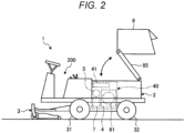
- Fig. 2 is a schematic view of the riding lawn mower 1
- Fig. 3 is an explanatory view showing in detail an engine room 40 provided in a running vehicle body 2 of the riding lawn mower 1.
- the inside of the engine room 40 is shown in a sectional view.
- the riding lawn mower 1 is operated by an operator (also referred to as a worker) who is seated on a driver's seat 20 provided in a front portion of the running vehicle body 2 having a vehicle body frame 21.
- a front and rear direction refers to a running direction when the riding lawn mower 1 goes straight.
- the front side in the running direction is defined as "the front,” and the rear side is defined as "the rear.”
- the running direction of the riding lawn mower 1 refers to a direction from the driver's seat 20 toward a steering wheel 201 when the riding lawn mower 1 goes straight.
- a left and right direction refers to a direction that is horizontally orthogonal to the front and rear direction.
- the left and right are defined toward “the front" side. That is, the left hand side refers to “the left” and the right hand side refers to “the right” with an operator seated on the driver's seat 20 and facing forward.
- an upper and lower direction refers to a vertical direction.
- the front and rear direction, the left and right direction, and the upper and lower direction are three-dimensionally orthogonal to each other.
- the respective directions are defined for the sake of easy understanding of the description, and the invention is not limited to these directions.
- the riding lawn mower 1 may be referred to as a machine body.
- the riding lawn mower 1 includes, as a pair of left and right running wheels, a pair of left and right front wheels 31 at the front portion of the running vehicle body 2 and a pair of left and right rear wheels 32 at the rear portion of the running vehicle body 2.
- the riding lawn mower 1 includes a mower device 3 in front of the lower portion of the running vehicle body 2 (see Fig. 5 ).
- the mower device 3 has a cutting blade 302 that rotates around a vertical axis (an axis extending in the upper and lower direction in Fig. 1 ), and a motor 303 that drives the cutting blade 302.
- the mower device 3 is vertically movably attached to the front of the running vehicle body 2 via a mower lifting device 330 (see Fig. 5 ).
- the riding lawn mower 1 includes a control part 200 at the front portion of the running vehicle body 2.
- the control part 200 includes the driver's seat 20, a floor step 202, a steering column 203, and the steering wheel 201.
- the floor step 202 is provided in front of the driver's seat 20.
- the steering column 203 is erected on the front portion of the floor step 202.
- the steering wheel 201 is provided above the steering column 203.
- an operation panel 204, various operation levers 205, various operation switches, and the like are provided above the steering column 203.
- a safety bar 206 is provided at the rear portion of the control part 200 so that it can be tilted back and forth.
- a collector 8 is provided behind the driver's seat 20 on the running vehicle body 2. That is, the collector 8 that is a grass collection container for storing grass or the like (hereinafter, referred to as grass) cut by the mower device 3 is vertically movably mounted above a bonnet 22 (see Figs. 8 to 10 ) covering the engine room 40 via a lifting arm 85, as shown in Fig. 2 .
- the lifting arm 85 constitutes a collector lifting device 800 (see Fig. 5 ) together with a lifting cylinder and the like (not shown).
- the engine room 40 is formed below the collector 8, and an engine 4 is mounted in the engine room 40.
- the riding lawn mower 1 includes the bonnet 22 that is provided at an upper portion of the engine room 40 and covers the engine 4. As shown, an engine fan 41 is attached to the bonnet 22. The bonnet 22 will be described in detail later. Further, a radiator 6 is arranged on the side of the engine 4 and on the back side of the plane of Fig. 3 (see Fig. 8 ).
- the engine 4 and an exhaust gas purification device 5 for purifying exhaust gas from the engine 4 are arranged in parallel inside the engine room 40.
- the exhaust gas purification device 5 is provided in the middle of an exhaust pipe 43 (see Fig. 1 ) that guides the exhaust gas from the engine 4 to the outside of the machine body.
- the engine 4 in the present embodiment is a diesel engine with a supercharger (turbocharger). However, the engine 4 may not have a supercharger.
- the exhaust gas purification device 5 has a well-known structure.
- the exhaust gas purification device 5 has a filter called a DPF (Diesel Particulate Filter) housed therein, and collects particles by allowing the exhaust gas to pass through the DPF. Further, since the DPF may be clogged due to the accumulation of the collected particles, the exhaust gas purification device 5 has a regeneration function of burning out the accumulated particles.
- DPF Diesel Particulate Filter
- the riding lawn mower 1 includes an air cleaner 610 for supplying clean air to the engine 4.
- the air cleaner 610 is connected to a pre-cleaner 620 arranged on the upper left side of the driver's seat 20.
- the pre-cleaner 620 is fixed to a machine body frame.
- the air cleaner 610 in the present embodiment is provided near the outside of the machine body, as shown in Fig. 1 . Therefore, the degree of freedom in arrangement is higher than when the air cleaner 610 is provided inside the machine body.
- the riding lawn mower 1 includes a transmission case 7 to which power from the engine 4 is transmitted.
- the transmission case 7 is arranged below the engine 4 on the side of the driver's seat 20.
- the exhaust gas purification device 5 is arranged above the transmission case 7. With this configuration, the exhaust gas purification device 5 can be arranged at a position as low as possible without causing a dead space in the engine room 40.
- the riding lawn mower 1 includes the collector 8, and accordingly, has a higher center of gravity, the exhaust gas purification device 5 can be arranged at a lower position. Therefore, the riding lawn mower 1 enables stable running by lowering the position of the center of gravity as a whole.
- the riding lawn mower 1 includes a blower case 208 having a blower 207 installed therein.
- the blower case 208 and the collector 8 are connected by a duct 209. Further, a shooter 210 is provided between the blower 207 and the mower device 3.
- the grass cut by the mower device 3 is sent from a mower deck 300 shown in Fig. 1 to the blower 207 via the shooter 210, and is further pneumatically conveyed to the collector 8 via the duct 209.
- a grass outlet 211 is formed at the end of the duct 209.
- the grass outlet 211 serves as a connecting portion with the collector 8. That is, when the collector 8 is in a lowered normal position, the grass outlet 211 overlaps an inlet (not shown) of the collector 8, and the duct 209 and the collector 8 are connected.
- the grass cut by the mower device 3 is sent into the collector 8 via the shooter 210 and the duct 209 by the blower 207.
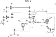
- Fig. 4 is a transmission line diagram of the riding lawn mower 1 according to the embodiment.
- the power (rotational power) output from the engine 4 is transmitted to a distribution transmission shaft 11 connected to an output shaft 10 of the engine 4, and is transmitted to a first PTO (Power Take-off) shaft (also referred to as a blower PTO shaft) 12A.
- the rotational power output from the blower PTO shaft 12A is transmitted to the above-described blower 207 via a blower transmission device (gear transmission device or the like), for example.
- reference numerals 16A, 16B indicate PTO clutches.
- the rotational power output from the distribution transmission shaft 11 is transmitted to driving wheels via a running transmission. That is, through a hydraulic pump 13a of a hydraulic continuously variable transmission (hereinafter, also referred to as HST (Hydro Static Transmission)) 13 accommodated in the transmission case 7, a trunnion shaft tilts to shift a hydraulic motor 13b.
- HST Hydrau Static Transmission
- the riding lawn mower 1 is configured to be switchable between two-wheel drive (2WD) and four-wheel drive (4WD). Therefore, when the riding lawn mower 1 is driven in 2WD, one (e.g., the left and right front wheels 31) of the left and right front wheels 31 and the left and right rear wheels 32 becomes driving wheels. When the riding lawn mower 1 is driven in 4WD, the left and right front wheels 31 and the left and right rear wheels 32 become driving wheels.
- the rotational power output from the distribution transmission shaft 11 is transmitted to the front wheels 31 via the hydraulic pump 13a and the hydraulic motor 13b of the HST 13 and via a gear transmission 14a and a differential gear mechanism 14b in a differential gear case 14. Further, the rotational power output from the distribution transmission shaft 11 is transmitted to the rear wheels 32 via the hydraulic pump 13a and the hydraulic motor 13b of the HST 13 and via a gear transmission 15a and a differential gear mechanism 15b in a differential gear case 15.
- the rotational power output from the distribution transmission shaft 11 is transmitted to a second PTO shaft (also referred to as a mower PTO shaft) 12B.
- the rotational power output from the mower PTO shaft 12B is transmitted to the above-described cutting blade via a mower input shaft 301 shown in Fig. 1 and a mower transmission (not shown) in the mower deck 300.
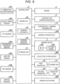
- Fig. 5 is a block diagram centering on the control part 9 of the riding lawn mower 1.
- the control part 9 can control each unit including various actuators 400 provided in the riding lawn mower 1 by electronic control, and includes a processing unit having a CPU (Central Processing Unit) and the like.
- a processing unit having a CPU (Central Processing Unit) and the like.
- control part 9 includes a storage unit 91 that stores a program for controlling the drive of a first fan motor 42 that drives the engine fan 41 and a second fan motor 63 that drives a radiator fan 61 and data necessary for driving the various actuators 400 and the like.
- the storage unit 91 includes a hard disk, a ROM (Read Only Memory), a RAM (Random Access Memory), and the like.
- control part 9 includes an engine ECU (Electronic Control Unit) 92, a running system ECU 93, and a working machine system ECU 94.
- engine ECU Electronic Control Unit
- the engine ECU 92 controls the output or the like of the engine 4, and the running system ECU 93 controls the continuously variable transmission 13 or the like, thereby controlling the overall running of the machine body.
- the working machine system ECU 94 controls the overall driving of the mower device 3.
- the working machine system ECU 94 controls a solenoid valve or the like for turning on and off the PTO clutches 16A, 16B (see Fig. 4 ) and also controls the mower lifting device 330 to control the lifting and lowering of the mower device 3.
- control part 9 is connected with a combustion system sensor 901, a vehicle speed sensor 902, a PTO sensor 903, a differential pressure sensor 904, an airflow sensor 905, a DPF sensor 906, and other various sensors 900.
- the combustion system sensor 901 detects the combustion state of the engine 4.
- the vehicle speed sensor 902 is provided to calculate the running speed (vehicle speed) of the machine body, and derives a measured value of the vehicle speed from the rotational speeds of the front wheels and the rear wheels.
- the PTO sensor 903 detects the rotation of the blower PTO shaft 12A and the mower PTO shaft 12B (see Fig. 4 ).
- the differential pressure sensor 904 is provided to detect the exhaust pressure before and after the exhaust gas purification device 5 connected in the middle of the exhaust pipe 43 (see Fig. 1 ).
- the airflow sensor 905 is a sensor for detecting the amount of air supplied to the engine 4 and is provided in the air cleaner 610.
- the DPF sensor 906 detects the degree of clogging of the DPF accommodated in the exhaust gas purification device 5.
- control part 9 acquires various data in each unit, and controls the operation of each unit of the machine body based on the data and the result calculated from the data and the like.
- Fig. 6 is an explanatory view of the exhaust gas purification device 5 provided in the riding lawn mower 1
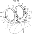
- Fig. 7A is an explanatory view of a connector 50 for mounting the exhaust gas purification device 5.
- the exhaust gas purification device 5 has a cylindrical body portion 500 that is a body portion of the exhaust gas purification device.
- An upstream side exhaust pipe 431 of the exhaust pipe 43 is connected to one end of the body portion 500, and a downstream side exhaust pipe 432 of the exhaust pipe 43 is connected to the other end.
- a leading end of the exhaust pipe 43 (the downstream side exhaust pipe 432) has an exhaust port opening toward the left side of the machine body.
- a diffuser at the exhaust port it is preferable to provide a diffuser at the exhaust port.
- the leading end of the exhaust pipe 43 (the downstream side exhaust pipe 432) may be opened to the rear of the machine body. In that case, the degree of freedom in designing the shape of the exhaust pipe 43 is increased, and the piping can be installed in parallel so that water is not collected.
- the exhaust gas purification device 5 is arranged at a height that does not protrude upward from the upper end of the engine 4. At that time, the exhaust gas purification device 5 is connected to an upper portion of the transmission case 7 via the predetermined connector 50.
- the connector 50 includes a pair of ring-shaped holder portions 51, 51 for holding the body portion 500 of the exhaust gas purification device 5, and a stay portion 52 to which the holder portions 51, 51 are attached and in which a connecting portion 520 with the transmission case 7 is formed.
- the stay portion 52 has a first stay member 521 connected to the transmission case 7, and a pair of second stay members 522, 522 connected to the holder portion 51, respectively.
- the first stay member 521 is formed in a substantially U-shape that has a flat plate-shaped bottom plate portion serving as the connecting portion 520 and upright pieces 5210, 5210 rising from both ends of the bottom plate portion. Further, the first stay member 521 can be connected to an upper portion of a flange portion 70 of the transmission case 7 at the connecting portion 520 by bolts 53, 53.
- the pair of left and right second stay members 522 are connected to the first stay member 521 by connecting screws 54, respectively.
- the holder portion 51 is welded to one side edge of the second stay member 522 formed in an arc shape.
- the holder portion 51 includes a semi-circular first holder 511 and a semi-circular second holder 512 abutted against and connected to the first holder 511 by screws 513, 513.
- the first holder 511 is welded to the second stay member 522.
- the first holder 511 and the second holder 512 can firmly hold the substantially cylindrical body portion 500 of the exhaust gas purification device 5. Further, when the screws 513 are loosened, the body portion 500 can be rotated in a circumferential direction and its mounting angle can be adjusted. In this way, the positioning of the body portion 500 is also easy, and thus, work such as piping connection is also easy.
- the stay portion 52 is divided into the first stay member 521 connected with the transmission case 7 and the second stay members 522 connected with the holder portions 51, respectively. Therefore, when the first stay member 521 is connected to the transmission case 7 in advance, it is easy to install the exhaust gas purification device 5 later and it is also easy to dismount it after the installation, so that maintenance is improved.
- the traveling lawn mower 1 in the present embodiment includes the collector 8, and accordingly, has a higher center of gravity
- the exhaust gas purification device 5 can be located as low as possible in the engine room 40 where the devices are generally densely installed. Therefore, it is possible to prevent the center of gravity from becoming higher even when the exhaust gas purification device 5 is provided, so that the driving stability can be secured.
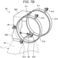
- Fig. 7B is an explanatory view showing a modification of the connector 50. That is, as shown in Fig. 7B , the connector 50 according to the modification includes an upper stay member 523 and a lower stay member 524 that are vertically separable.
- the semi-circular first holder 511 is welded to the upper stay member 523.
- the configuration of the holder portion 51 is similar to that shown in Fig. 7B .
- the holder portion 51 includes the semi-circular first holder 511 and the semi-circular second holder 512 abutted against and connected to the first holder 511 by the screws 513, 513.
- the connecting screws 54 can be similarly used to connect the upper stay member 523 and the lower stay member 524. At this time, the connecting screws 54 are welded to the lower stay member 524 to form weld buttons. The connecting screws 54 can be passed through connecting holes formed in the upper stay member 523 and can be tightened with nuts or the like. In this way, it is easy to assemble the upper stay member 523 and the lower stay member 524.
- the connector 50 is configured such that the stay portion is separable like the first stay member 521 and the second stay member 522, or the upper stay member 523 and the lower stay member 524. Therefore, for example, when the first stay member 521 or the lower stay member 524 is fixed to the transmission case 7 in advance, the second stay member 522 or the upper stay member 523, to which the holder portions 51 that hold the exhaust gas purification device 5 are connected, can be easily attached to the transmission case 7.
- the riding lawn mower 1 includes a device cover 55 that covers the exhaust gas purification device 5. That is, as shown in Fig. 3 , the engine fan 41, which will be described in detail later, is provided above the exhaust gas purification device 5, and the DPF accommodated in the exhaust gas purification device 5 needs to burn the deposited particles, as described above. At that time, the device cover 55 is provided to maintain the DPF in a high temperature state, so that the DPF can be protected from the wind of the engine fan 41.
- the device cover 55 has a flat surface portion 551 and a hanging portion 552 formed by bending a long side portion of the flat surface portion 551 downward.
- the device cover 55 is shaped to enclose the exhaust gas purification device 5. Therefore, for example, the device cover 55 prevents grass and the like from falling from above to the exhaust gas purification device 5, thereby preventing the occurrence of a fire or the like in advance.
- harnesses, hydraulic hoses, and the like are arranged above the flat surface portion 551 and protected from the heat of the DPF when the DPF becomes hot.
- the hanging portion 552 serves as a baffle plate that guides the wind from the engine fan 41 to the engine 4 while keeping the wind away from the exhaust gas purification device 5.
- the hanging portion 552 in the present embodiment is bent in a substantially vertical direction, the bending angle of the hanging portion 552 can be set to an appropriate angle.
- the device cover 55 is provided with a shielding plate portion 553 on the side opposite to the hanging portion 552 so that hot wind does not flow to the driver's seat 20.
- the shielding plate portion 553 can prevent a driver sitting on the driver's seat 20 from being exposed to hot wind, thereby preventing discomfort to the driver.
- Fig. 8 is an explanatory view showing an arrangement of the bonnet 22 covering the engine room 40 and the radiator fan 61
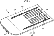
- Fig. 9 is an explanatory view of the bonnet 22
- Fig. 10 is an explanatory view of the engine fan 41 provided on the back side of the bonnet 22.
- the radiator 6 and the radiator fan 61 will be described. As shown in Fig. 8 , the radiator 6 is provided on the right side of the machine body (on the right side of the engine 4). Further, the radiator fan 61 is provided on the inner side of a radiator net 62 that is provided on the outer side of the radiator 6 to prevent entrance of dust. That is, the radiator fan 61 for blowing air to the radiator 6 is arranged adjacent to the side of the radiator 6.
- a pipe of a fuel cooler is arranged along an outer surface of the radiator 6 so that it can be cooled by the radiator fan 61.
- the pipe of the fuel cooler includes a supply pipe and a return pipe, both of which are vertically arranged along the outer surface of the radiator 6.
- the bonnet 22 is provided above the engine room 40 so that it can be opened and closed up and down via a hinge portion 225. That is, the bonnet 22 has a substantially rectangular shape and includes a plate-like body 220 having a surface facing the engine 4. An air intake portion 222 having a plurality of vent holes 221 and a cover portion 223 covering the upper portion of each vent hole 221 is formed in the plate-like body 220. A plurality of the air intake portions 222 are provided in two rows between a pair of slits 226, 226 provided in parallel along a longitudinal direction of the plate-like body 220. Further, a handle 224 is formed on the front side of the surface of the plate-like body 220, and the hinge portion 225 is provided at the rear end of the plate-like body 220.
- the vent hole 221 is formed in an elongated rectangular shape facing the engine 4, and the cover portion 223 is formed in a shape rising diagonally rearward from a long side portion on the front side of the vent hole 221.
- the engine fan 41 is attached to the back side of the plate-like body 220. That is, the engine fan 41 for blowing air to the engine 4 is arranged above the engine 4.
- the same fan can be used for the engine fan 41 and the radiator fan 61, so that the parts management can be rationally done and cost reduction can be achieved.
- the engine fan 41 is connected to the first fan motor 42.
- the engine fan 41 and the first fan motor 42 are connected together to a guard body 47 for protecting the engine fan 41.
- the guard body 47 is connected to a cut-and-raised piece cut and raised to form the slit 226.
- the engine fan 41 is provided on the back side of the bonnet 22 where the air intake portions 222 are formed, and, as shown in Fig. 3 , the engine fan 41 and the engine 4 are arranged to face each other. Therefore, the outside air can be efficiently drawn into the engine room 40, and the engine 4 can be efficiently cooled.
- the collector 8 for storing grass is arranged above the bonnet 22.
- the air intake portion 222 is provided with the cover portion 223 covering the vent hole 221, it is possible to prevent grass or the like from entering the engine room 40 as much as possible.
- the grass outlet 211 which is a connecting portion between the collector 8 and the duct 209, is provided in front of the vent hole 221, and the cover portion 223 is formed in a shape rising diagonally rearward from the front side of the vent hole 221. Therefore, it is possible to more efficiently prevent grass or the like from entering the engine room 40.
- the riding lawn mower 1 includes the engine fan 41 and the radiator fan 61.
- the engine fan 41 and the radiator fan 61 are configured such that one of both rotates in a suction direction and the other rotates in a blowing direction.
- the radiator fan 61 rotates in the suction direction and the engine fan 41 rotates in the blowing direction. Therefore, the engine 4 and the radiator 6 in the engine room 40 can be efficiently cooled. That is, since the flow without heated air staying can be generated between the side and the upper side of the engine 4, the engine 4 can be sufficiently cooled.
- the engine fan 41 and the radiator fan 61 are drive-controlled by the control part 9 and can be reversed in the forward and reverse directions according to predetermined conditions.
- the control part 9 can rotate the radiator fan 61 in the blowing direction and rotate the engine fan 41 in the suction direction.
- the dust accumulated on the radiator net 62 can be blown out and removed by reversing the flow of air. Further, when the forward and reverse directions are switched in conjunction with the post-treatment regeneration of the DPF, the wind for blowing out dust becomes easier to pass through the radiator net 62, and dust can be efficiently removed.
- control part 9 can rotate the engine fan 41 in the blowing direction when the collector 8 is raised. With this control, it is possible to prevent the grass that has fallen from the collector 8 from entering the engine room 40.
- an inclined portion may be provided in a return portion from a breather (not shown) of the engine 4 so that oil return or the like does not occur in the airflow sensor 905 provided in an intake path (not shown) from the pre-cleaner 620 to the engine 4.
- the engine 4 has a supercharger, so that there is no problem even when the intake path to the engine 4 becomes long, and the degree of freedom in designing the air supply path is increased.
- the air supply path is as short as possible.
- the pre-cleaner 620 may be arranged near the air cleaner 610 to shorten the air supply path.
- a hose of the return portion from the breather is made of oil-resistant AEM (ethylene/acrylic/rubber) in order to increase resistance to oil vapor.
- AEM oil-resistant ethylene/acrylic/rubber
Landscapes
- Life Sciences & Earth Sciences (AREA)
- Environmental Sciences (AREA)
- Cooling, Air Intake And Gas Exhaust, And Fuel Tank Arrangements In Propulsion Units (AREA)
- Harvester Elements (AREA)
Description
- The present invention relates to a riding lawn mower.
- Conventionally, there is known a working vehicle in which an engine is mounted on a rear portion of a running vehicle, and a radiator and a radiator fan are attached to an inner side of a cover that opens and closes an engine room for accommodating the engine (see
JP 2009 202684 A - However, in the above conventional working vehicle, the accessibility to the radiator, maintenance and assembly are improved, but there is a possibility that the air flow stays and sufficient cooling performance for the engine cannot be obtained.
-
EP 3 153 342 A1JP 2003 154857 claim 1. - The invention has been made in view of the above situations, and an object thereof is to provide a riding lawn mower in which an engine can be sufficiently cooled.
- In order to solve the above-described problems and achieve the object, there is provided a riding lawn mower as specified in
claim 1. - According to the riding lawn mower specified in
claim 1, the engine can be sufficiently cooled. -
-
Fig. 1 is a side view of a riding lawn mower according to an embodiment; -
Fig. 2 is a schematic view of the riding lawn mower; -
Fig. 3 is an explanatory view showing in detail an engine room provided in a running vehicle body of the riding lawn mower; -
Fig. 4 is a transmission line diagram of the riding lawn mower; -
Fig. 5 is a block diagram centering on a control part of the riding lawn mower; -
Fig. 6 is an explanatory view of an exhaust gas purification device provided in the riding lawn mower; -
Fig. 7A is an explanatory view of a connector for mounting the exhaust gas purification device; -
Fig. 7B is an explanatory view showing a modification of the connector; -
Fig. 8 is an explanatory view showing an arrangement of a bonnet covering the engine room and a radiator fan; -
Fig. 9 is an explanatory view of the bonnet; and -
Fig. 10 is an explanatory view of an engine fan provided on the back side of the bonnet. - Hereinafter, an embodiment of a riding lawn mower disclosed in the present application will be described in detail with reference to the accompanying drawings. The invention is not limited to the embodiments described below.
- First, an overall configuration of a
riding lawn mower 1 will be briefly described with reference toFigs. 1 to 3 .Fig. 1 is a side view of theriding lawn mower 1 according to an embodiment,Fig. 2 is a schematic view of theriding lawn mower 1, andFig. 3 is an explanatory view showing in detail anengine room 40 provided in a runningvehicle body 2 of theriding lawn mower 1. InFig. 3 , the inside of theengine room 40 is shown in a sectional view. - The
riding lawn mower 1 is operated by an operator (also referred to as a worker) who is seated on a driver'sseat 20 provided in a front portion of the runningvehicle body 2 having avehicle body frame 21. In the following, a front and rear direction refers to a running direction when theriding lawn mower 1 goes straight. The front side in the running direction is defined as "the front," and the rear side is defined as "the rear." The running direction of theriding lawn mower 1 refers to a direction from the driver'sseat 20 toward asteering wheel 201 when theriding lawn mower 1 goes straight. - Further, a left and right direction refers to a direction that is horizontally orthogonal to the front and rear direction. In the following description, the left and right are defined toward "the front" side. That is, the left hand side refers to "the left" and the right hand side refers to "the right" with an operator seated on the driver's
seat 20 and facing forward. Further, an upper and lower direction refers to a vertical direction. The front and rear direction, the left and right direction, and the upper and lower direction are three-dimensionally orthogonal to each other. The respective directions are defined for the sake of easy understanding of the description, and the invention is not limited to these directions. In the following, theriding lawn mower 1 may be referred to as a machine body. - As shown in
Figs. 1 to 3 , theriding lawn mower 1 includes, as a pair of left and right running wheels, a pair of left and rightfront wheels 31 at the front portion of the runningvehicle body 2 and a pair of left and rightrear wheels 32 at the rear portion of the runningvehicle body 2. - Further, the
riding lawn mower 1 includes amower device 3 in front of the lower portion of the running vehicle body 2 (seeFig. 5 ). Themower device 3 has acutting blade 302 that rotates around a vertical axis (an axis extending in the upper and lower direction inFig. 1 ), and amotor 303 that drives thecutting blade 302. Themower device 3 is vertically movably attached to the front of therunning vehicle body 2 via a mower lifting device 330 (seeFig. 5 ). - Further, the
riding lawn mower 1 includes acontrol part 200 at the front portion of therunning vehicle body 2. Thecontrol part 200 includes the driver'sseat 20, afloor step 202, asteering column 203, and thesteering wheel 201. Thefloor step 202 is provided in front of the driver'sseat 20. Thesteering column 203 is erected on the front portion of thefloor step 202. Thesteering wheel 201 is provided above thesteering column 203. In addition to thesteering wheel 201, anoperation panel 204, various operation levers 205, various operation switches, and the like are provided above thesteering column 203. Further, asafety bar 206 is provided at the rear portion of thecontrol part 200 so that it can be tilted back and forth. - Further, a
collector 8 is provided behind the driver'sseat 20 on therunning vehicle body 2. That is, thecollector 8 that is a grass collection container for storing grass or the like (hereinafter, referred to as grass) cut by themower device 3 is vertically movably mounted above a bonnet 22 (seeFigs. 8 to 10 ) covering theengine room 40 via alifting arm 85, as shown inFig. 2 . Thelifting arm 85 constitutes a collector lifting device 800 (seeFig. 5 ) together with a lifting cylinder and the like (not shown). - Further, as shown in
Figs. 2 and3 , on the rear side of the driver's seat 20 (seeFig. 1 ) in theriding lawn mower 1, theengine room 40 is formed below thecollector 8, and anengine 4 is mounted in theengine room 40. Further, theriding lawn mower 1 includes thebonnet 22 that is provided at an upper portion of theengine room 40 and covers theengine 4. As shown, anengine fan 41 is attached to thebonnet 22. Thebonnet 22 will be described in detail later. Further, a radiator 6 is arranged on the side of theengine 4 and on the back side of the plane ofFig. 3 (seeFig. 8 ). - The
engine 4 and an exhaustgas purification device 5 for purifying exhaust gas from theengine 4 are arranged in parallel inside theengine room 40. The exhaustgas purification device 5 is provided in the middle of an exhaust pipe 43 (seeFig. 1 ) that guides the exhaust gas from theengine 4 to the outside of the machine body. - The
engine 4 in the present embodiment is a diesel engine with a supercharger (turbocharger). However, theengine 4 may not have a supercharger. - The exhaust
gas purification device 5 has a well-known structure. The exhaustgas purification device 5 has a filter called a DPF (Diesel Particulate Filter) housed therein, and collects particles by allowing the exhaust gas to pass through the DPF. Further, since the DPF may be clogged due to the accumulation of the collected particles, the exhaustgas purification device 5 has a regeneration function of burning out the accumulated particles. - Further, the riding
lawn mower 1 includes anair cleaner 610 for supplying clean air to theengine 4. Theair cleaner 610 is connected to a pre-cleaner 620 arranged on the upper left side of the driver'sseat 20. The pre-cleaner 620 is fixed to a machine body frame. - Further, the
air cleaner 610 in the present embodiment is provided near the outside of the machine body, as shown inFig. 1 . Therefore, the degree of freedom in arrangement is higher than when theair cleaner 610 is provided inside the machine body. - Further, the riding
lawn mower 1 includes atransmission case 7 to which power from theengine 4 is transmitted. Thetransmission case 7 is arranged below theengine 4 on the side of the driver'sseat 20. In the ridinglawn mower 1 according to the present embodiment, the exhaustgas purification device 5 is arranged above thetransmission case 7. With this configuration, the exhaustgas purification device 5 can be arranged at a position as low as possible without causing a dead space in theengine room 40. - In this way, although the riding
lawn mower 1 according to the present embodiment includes thecollector 8, and accordingly, has a higher center of gravity, the exhaustgas purification device 5 can be arranged at a lower position. Therefore, the ridinglawn mower 1 enables stable running by lowering the position of the center of gravity as a whole. - Further, as shown in
Fig. 3 , the ridinglawn mower 1 includes ablower case 208 having ablower 207 installed therein. Theblower case 208 and thecollector 8 are connected by aduct 209. Further, ashooter 210 is provided between theblower 207 and themower device 3. - Thus, in the riding
lawn mower 1, the grass cut by themower device 3 is sent from amower deck 300 shown inFig. 1 to theblower 207 via theshooter 210, and is further pneumatically conveyed to thecollector 8 via theduct 209. - As shown in
Fig. 3 , agrass outlet 211 is formed at the end of theduct 209. Thegrass outlet 211 serves as a connecting portion with thecollector 8. That is, when thecollector 8 is in a lowered normal position, thegrass outlet 211 overlaps an inlet (not shown) of thecollector 8, and theduct 209 and thecollector 8 are connected. The grass cut by themower device 3 is sent into thecollector 8 via theshooter 210 and theduct 209 by theblower 207. - Next, a transmission configuration of the riding
lawn mower 1 will be briefly described with reference toFig. 4. Fig. 4 is a transmission line diagram of the ridinglawn mower 1 according to the embodiment. As shown inFig. 4 , in the ridinglawn mower 1, the power (rotational power) output from theengine 4 is transmitted to adistribution transmission shaft 11 connected to anoutput shaft 10 of theengine 4, and is transmitted to a first PTO (Power Take-off) shaft (also referred to as a blower PTO shaft) 12A. The rotational power output from theblower PTO shaft 12A is transmitted to the above-describedblower 207 via a blower transmission device (gear transmission device or the like), for example. InFig. 4 ,reference numerals - Further, the rotational power output from the
distribution transmission shaft 11 is transmitted to driving wheels via a running transmission. That is, through ahydraulic pump 13a of a hydraulic continuously variable transmission (hereinafter, also referred to as HST (Hydro Static Transmission)) 13 accommodated in thetransmission case 7, a trunnion shaft tilts to shift ahydraulic motor 13b. - By the way, the riding
lawn mower 1 is configured to be switchable between two-wheel drive (2WD) and four-wheel drive (4WD). Therefore, when the ridinglawn mower 1 is driven in 2WD, one (e.g., the left and right front wheels 31) of the left and rightfront wheels 31 and the left and rightrear wheels 32 becomes driving wheels. When the ridinglawn mower 1 is driven in 4WD, the left and rightfront wheels 31 and the left and rightrear wheels 32 become driving wheels. - In case of 4WD, the rotational power output from the
distribution transmission shaft 11 is transmitted to thefront wheels 31 via thehydraulic pump 13a and thehydraulic motor 13b of theHST 13 and via a gear transmission 14a and adifferential gear mechanism 14b in adifferential gear case 14. Further, the rotational power output from thedistribution transmission shaft 11 is transmitted to therear wheels 32 via thehydraulic pump 13a and thehydraulic motor 13b of theHST 13 and via agear transmission 15a and adifferential gear mechanism 15b in adifferential gear case 15. - Further, the rotational power output from the
distribution transmission shaft 11 is transmitted to a second PTO shaft (also referred to as a mower PTO shaft) 12B. The rotational power output from themower PTO shaft 12B is transmitted to the above-described cutting blade via amower input shaft 301 shown inFig. 1 and a mower transmission (not shown) in themower deck 300. - Here, a control system of the riding
lawn mower 1 centering on acontrol part 9 will be described with reference toFig. 5. Fig. 5 is a block diagram centering on thecontrol part 9 of the ridinglawn mower 1. - The
control part 9 can control each unit including various actuators 400 provided in the ridinglawn mower 1 by electronic control, and includes a processing unit having a CPU (Central Processing Unit) and the like. - Further, the
control part 9 includes a storage unit 91 that stores a program for controlling the drive of afirst fan motor 42 that drives theengine fan 41 and asecond fan motor 63 that drives aradiator fan 61 and data necessary for driving the various actuators 400 and the like. The storage unit 91 includes a hard disk, a ROM (Read Only Memory), a RAM (Random Access Memory), and the like. - Further, the
control part 9 includes an engine ECU (Electronic Control Unit) 92, a running system ECU 93, and a workingmachine system ECU 94. - The engine ECU 92 controls the output or the like of the
engine 4, and the running system ECU 93 controls the continuouslyvariable transmission 13 or the like, thereby controlling the overall running of the machine body. The workingmachine system ECU 94 controls the overall driving of themower device 3. The workingmachine system ECU 94 controls a solenoid valve or the like for turning on and off thePTO clutches Fig. 4 ) and also controls themower lifting device 330 to control the lifting and lowering of themower device 3. - Further, the
control part 9 is connected with acombustion system sensor 901, a vehicle speed sensor 902, aPTO sensor 903, adifferential pressure sensor 904, anairflow sensor 905, aDPF sensor 906, and othervarious sensors 900. - The
combustion system sensor 901 detects the combustion state of theengine 4. The vehicle speed sensor 902 is provided to calculate the running speed (vehicle speed) of the machine body, and derives a measured value of the vehicle speed from the rotational speeds of the front wheels and the rear wheels. ThePTO sensor 903 detects the rotation of theblower PTO shaft 12A and themower PTO shaft 12B (seeFig. 4 ). - The
differential pressure sensor 904 is provided to detect the exhaust pressure before and after the exhaustgas purification device 5 connected in the middle of the exhaust pipe 43 (seeFig. 1 ). Theairflow sensor 905 is a sensor for detecting the amount of air supplied to theengine 4 and is provided in theair cleaner 610. TheDPF sensor 906 detects the degree of clogging of the DPF accommodated in the exhaustgas purification device 5. - In this manner, the
control part 9 acquires various data in each unit, and controls the operation of each unit of the machine body based on the data and the result calculated from the data and the like. - Next, a mounting structure of the exhaust
gas purification device 5 will be specifically described with reference toFigs. 3 and6 to 7A .Fig. 6 is an explanatory view of the exhaustgas purification device 5 provided in the ridinglawn mower 1, andFig. 7A is an explanatory view of aconnector 50 for mounting the exhaustgas purification device 5. - As shown in
Fig. 6 , the exhaustgas purification device 5 has acylindrical body portion 500 that is a body portion of the exhaust gas purification device. An upstream side exhaust pipe 431 of theexhaust pipe 43 is connected to one end of thebody portion 500, and a downstreamside exhaust pipe 432 of theexhaust pipe 43 is connected to the other end. - By the way, in the present embodiment, a leading end of the exhaust pipe 43 (the downstream side exhaust pipe 432) has an exhaust port opening toward the left side of the machine body. However, it is preferable to provide a diffuser at the exhaust port. With this configuration, there is no danger of ignition of abandoned grass due to hot exhaust gas.
- When the
mower device 3 is configured to discharge the mowed grass laterally and there is no danger of ignition of the abandoned grass left behind, the leading end of the exhaust pipe 43 (the downstream side exhaust pipe 432) may be opened to the rear of the machine body. In that case, the degree of freedom in designing the shape of theexhaust pipe 43 is increased, and the piping can be installed in parallel so that water is not collected. - Further, as shown in
Fig. 3 , the exhaustgas purification device 5 is arranged at a height that does not protrude upward from the upper end of theengine 4. At that time, the exhaustgas purification device 5 is connected to an upper portion of thetransmission case 7 via thepredetermined connector 50. - As shown in
Fig. 7A , theconnector 50 includes a pair of ring-shapedholder portions body portion 500 of the exhaustgas purification device 5, and astay portion 52 to which theholder portions portion 520 with thetransmission case 7 is formed. - Further, the
stay portion 52 has afirst stay member 521 connected to thetransmission case 7, and a pair ofsecond stay members holder portion 51, respectively. - The
first stay member 521 is formed in a substantially U-shape that has a flat plate-shaped bottom plate portion serving as the connectingportion 520 andupright pieces first stay member 521 can be connected to an upper portion of aflange portion 70 of thetransmission case 7 at the connectingportion 520 bybolts - The pair of left and right
second stay members 522 are connected to thefirst stay member 521 by connectingscrews 54, respectively. Theholder portion 51 is welded to one side edge of thesecond stay member 522 formed in an arc shape. - The
holder portion 51 includes a semi-circularfirst holder 511 and a semi-circularsecond holder 512 abutted against and connected to thefirst holder 511 byscrews first holder 511 is welded to thesecond stay member 522. - With this configuration, the
first holder 511 and thesecond holder 512 can firmly hold the substantiallycylindrical body portion 500 of the exhaustgas purification device 5. Further, when thescrews 513 are loosened, thebody portion 500 can be rotated in a circumferential direction and its mounting angle can be adjusted. In this way, the positioning of thebody portion 500 is also easy, and thus, work such as piping connection is also easy. - Further, the
stay portion 52 is divided into thefirst stay member 521 connected with thetransmission case 7 and thesecond stay members 522 connected with theholder portions 51, respectively. Therefore, when thefirst stay member 521 is connected to thetransmission case 7 in advance, it is easy to install the exhaustgas purification device 5 later and it is also easy to dismount it after the installation, so that maintenance is improved. - In this way, although the riding
lawn mower 1 in the present embodiment includes thecollector 8, and accordingly, has a higher center of gravity, the exhaustgas purification device 5 can be located as low as possible in theengine room 40 where the devices are generally densely installed. Therefore, it is possible to prevent the center of gravity from becoming higher even when the exhaustgas purification device 5 is provided, so that the driving stability can be secured. - By the way, the
connector 50 may have a configuration described below.Fig. 7B is an explanatory view showing a modification of theconnector 50. That is, as shown inFig. 7B , theconnector 50 according to the modification includes anupper stay member 523 and alower stay member 524 that are vertically separable. The semi-circularfirst holder 511 is welded to theupper stay member 523. The configuration of theholder portion 51 is similar to that shown inFig. 7B . Theholder portion 51 includes the semi-circularfirst holder 511 and the semi-circularsecond holder 512 abutted against and connected to thefirst holder 511 by thescrews - The connecting screws 54 can be similarly used to connect the
upper stay member 523 and thelower stay member 524. At this time, the connectingscrews 54 are welded to thelower stay member 524 to form weld buttons. The connecting screws 54 can be passed through connecting holes formed in theupper stay member 523 and can be tightened with nuts or the like. In this way, it is easy to assemble theupper stay member 523 and thelower stay member 524. - The
connector 50 is configured such that the stay portion is separable like thefirst stay member 521 and thesecond stay member 522, or theupper stay member 523 and thelower stay member 524. Therefore, for example, when thefirst stay member 521 or thelower stay member 524 is fixed to thetransmission case 7 in advance, thesecond stay member 522 or theupper stay member 523, to which theholder portions 51 that hold the exhaustgas purification device 5 are connected, can be easily attached to thetransmission case 7. - Further, as shown in
Fig. 6 , the ridinglawn mower 1 according to the present embodiment includes adevice cover 55 that covers the exhaustgas purification device 5. That is, as shown inFig. 3 , theengine fan 41, which will be described in detail later, is provided above the exhaustgas purification device 5, and the DPF accommodated in the exhaustgas purification device 5 needs to burn the deposited particles, as described above. At that time, thedevice cover 55 is provided to maintain the DPF in a high temperature state, so that the DPF can be protected from the wind of theengine fan 41. - As shown in
Fig. 6 , thedevice cover 55 has aflat surface portion 551 and a hangingportion 552 formed by bending a long side portion of theflat surface portion 551 downward. Thedevice cover 55 is shaped to enclose the exhaustgas purification device 5. Therefore, for example, thedevice cover 55 prevents grass and the like from falling from above to the exhaustgas purification device 5, thereby preventing the occurrence of a fire or the like in advance. Further, for example, harnesses, hydraulic hoses, and the like are arranged above theflat surface portion 551 and protected from the heat of the DPF when the DPF becomes hot. - Further, the hanging
portion 552 serves as a baffle plate that guides the wind from theengine fan 41 to theengine 4 while keeping the wind away from the exhaustgas purification device 5. Although the hangingportion 552 in the present embodiment is bent in a substantially vertical direction, the bending angle of the hangingportion 552 can be set to an appropriate angle. - Further, the
device cover 55 is provided with ashielding plate portion 553 on the side opposite to the hangingportion 552 so that hot wind does not flow to the driver'sseat 20. The shieldingplate portion 553 can prevent a driver sitting on the driver'sseat 20 from being exposed to hot wind, thereby preventing discomfort to the driver. - Next, the
engine fan 41 and theradiator fan 61 will be described with reference toFigs. 8 to 10 .Fig. 8 is an explanatory view showing an arrangement of thebonnet 22 covering theengine room 40 and theradiator fan 61,Fig. 9 is an explanatory view of thebonnet 22, andFig. 10 is an explanatory view of theengine fan 41 provided on the back side of thebonnet 22. - First, the radiator 6 and the
radiator fan 61 will be described. As shown inFig. 8 , the radiator 6 is provided on the right side of the machine body (on the right side of the engine 4). Further, theradiator fan 61 is provided on the inner side of a radiator net 62 that is provided on the outer side of the radiator 6 to prevent entrance of dust. That is, theradiator fan 61 for blowing air to the radiator 6 is arranged adjacent to the side of the radiator 6. - Although not shown, a pipe of a fuel cooler is arranged along an outer surface of the radiator 6 so that it can be cooled by the
radiator fan 61. The pipe of the fuel cooler includes a supply pipe and a return pipe, both of which are vertically arranged along the outer surface of the radiator 6. - Further, the
bonnet 22 is provided above theengine room 40 so that it can be opened and closed up and down via ahinge portion 225. That is, thebonnet 22 has a substantially rectangular shape and includes a plate-like body 220 having a surface facing theengine 4. Anair intake portion 222 having a plurality of vent holes 221 and acover portion 223 covering the upper portion of eachvent hole 221 is formed in the plate-like body 220. A plurality of theair intake portions 222 are provided in two rows between a pair ofslits like body 220. Further, ahandle 224 is formed on the front side of the surface of the plate-like body 220, and thehinge portion 225 is provided at the rear end of the plate-like body 220. - The
vent hole 221 is formed in an elongated rectangular shape facing theengine 4, and thecover portion 223 is formed in a shape rising diagonally rearward from a long side portion on the front side of thevent hole 221. - Further, as shown in
Fig. 10 , theengine fan 41 is attached to the back side of the plate-like body 220. That is, theengine fan 41 for blowing air to theengine 4 is arranged above theengine 4. The same fan can be used for theengine fan 41 and theradiator fan 61, so that the parts management can be rationally done and cost reduction can be achieved. - The
engine fan 41 is connected to thefirst fan motor 42. Theengine fan 41 and thefirst fan motor 42 are connected together to a guard body 47 for protecting theengine fan 41. The guard body 47 is connected to a cut-and-raised piece cut and raised to form theslit 226. - In this manner, the
engine fan 41 is provided on the back side of thebonnet 22 where theair intake portions 222 are formed, and, as shown inFig. 3 , theengine fan 41 and theengine 4 are arranged to face each other. Therefore, the outside air can be efficiently drawn into theengine room 40, and theengine 4 can be efficiently cooled. - The
collector 8 for storing grass is arranged above thebonnet 22. However, since theair intake portion 222 is provided with thecover portion 223 covering thevent hole 221, it is possible to prevent grass or the like from entering theengine room 40 as much as possible. - Moreover, as described above, the
grass outlet 211, which is a connecting portion between thecollector 8 and theduct 209, is provided in front of thevent hole 221, and thecover portion 223 is formed in a shape rising diagonally rearward from the front side of thevent hole 221. Therefore, it is possible to more efficiently prevent grass or the like from entering theengine room 40. - As described above, the riding
lawn mower 1 according to the present embodiment includes theengine fan 41 and theradiator fan 61. Theengine fan 41 and theradiator fan 61 are configured such that one of both rotates in a suction direction and the other rotates in a blowing direction. - In the present embodiment, the
radiator fan 61 rotates in the suction direction and theengine fan 41 rotates in the blowing direction. Therefore, theengine 4 and the radiator 6 in theengine room 40 can be efficiently cooled. That is, since the flow without heated air staying can be generated between the side and the upper side of theengine 4, theengine 4 can be sufficiently cooled. - Further, as shown in
Fig. 5 , theengine fan 41 and theradiator fan 61 are drive-controlled by thecontrol part 9 and can be reversed in the forward and reverse directions according to predetermined conditions. For example, when the exhaustgas purification device 5 performs the combustion function (post-treatment regeneration) of the DPF, thecontrol part 9 can rotate theradiator fan 61 in the blowing direction and rotate theengine fan 41 in the suction direction. - By controlling in this way, during the post-treatment regeneration of the DPF, the dust accumulated on the
radiator net 62 can be blown out and removed by reversing the flow of air. Further, when the forward and reverse directions are switched in conjunction with the post-treatment regeneration of the DPF, the wind for blowing out dust becomes easier to pass through theradiator net 62, and dust can be efficiently removed. - Further, even when the
engine fan 41 rotates in the suction direction, thecontrol part 9 can rotate theengine fan 41 in the blowing direction when thecollector 8 is raised. With this control, it is possible to prevent the grass that has fallen from thecollector 8 from entering theengine room 40. - In this way, in the riding
lawn mower 1 according to the present embodiment, it is possible to appropriately cool theengine 4 according to its driving state and the like. - Although the riding
lawn mower 1 according to the present embodiment has the above-described configuration, for example, an inclined portion may be provided in a return portion from a breather (not shown) of theengine 4 so that oil return or the like does not occur in theairflow sensor 905 provided in an intake path (not shown) from the pre-cleaner 620 to theengine 4. - Further, in the present embodiment, the
engine 4 has a supercharger, so that there is no problem even when the intake path to theengine 4 becomes long, and the degree of freedom in designing the air supply path is increased. However, when the engine has no supercharger, it is preferable that the air supply path is as short as possible. In that case, the pre-cleaner 620 may be arranged near theair cleaner 610 to shorten the air supply path. - Further, it is preferable that a hose of the return portion from the breather is made of oil-resistant AEM (ethylene/acrylic/rubber) in order to increase resistance to oil vapor.
- Further effects and modifications can be easily derived by those skilled in the art. Therefore, the broader aspects of the invention are not limited to the particular details and representative embodiments shown and described above. In this way, various changes can be made without departing from the scope defined by the appended claims.
-
- 1
- Riding lawn mower
- 2
- Running vehicle body
- 3
- Mower device (working machine)
- 4
- Engine
- 5
- Exhaust gas purification device
- 6
- Radiator
- 7
- Transmission case
- 8
- Collector (Grass collection container)
- 9
- Control part
- 20
- Driver's seat
- 22
- Bonnet
- 31
- Front wheel (running wheel)
- 32
- Rear wheel (running wheel)
- 40
- Engine room
- 41
- Engine fan
- 50
- Connector
- 51
- Holder portion
- 52
- Stay portion
- 61
- Radiator fan
- 209
- Duct
- 211
- Grass outlet (Connecting portion)
- 221
- Vent hole
- 223
- Cover portion
- 520
- Connecting portion
- 521
- First stay member
- 522
- Second stay member
Claims (7)
- A riding lawn mower (1) comprising:a running vehicle body (2) which comprises running wheels (31, 32) and to which a mower device (3) can be connected;an engine (4) mounted on the running vehicle body (2);a radiator (6);a radiator fan (61) arranged near the radiator (6) for blowing air to the radiator (6); andan engine fan (41) for blowing air to the engine (4),characterized in thatthe engine fan (41) is arranged above the engine (4), andthe radiator fan (61) is a provided on a side of the engine (4) facing in a direction horizontally orthogonal to a front and rear direction of the riding lawn mower (1).
- The riding lawn mower (1) according to claim 1,wherein the running vehicle body (2) comprisesa grass collection container (8) arranged above the engine (4) and configured to collect grass cut by the mower device (3) through a duct (209), anda bonnet (22) for covering an engine room (40) that accommodates the engine (4) and the radiator (6), andwherein the bonnet (22) has a vent hole (221) formed in a surface facing the engine (4) and a cover portion (223) for covering the upper portion of the vent hole (221).
- The riding lawn mower (1) according to claim 2,wherein a connecting portion (211) between the grass collection container (8) and the duct (209) is provided in front of the vent hole (221), andwherein the cover portion (223) is formed in a shape rising diagonally rearward from the front side of the vent hole (221).
- The riding lawn mower (1) according to any one of claims 1 to 3,
wherein one of the engine fan (41) and the radiator fan (61) rotates in a suction direction, and the other rotates in a blowing direction. - The riding lawn mower (1) according to claim 4,
wherein the radiator fan (61) rotates in the suction direction, and the engine fan (41) rotates in the blowing direction. - The riding lawn mower (1) according to claim 5, comprisinga control part (9) capable of switching the rotation directions of the radiator fan (61) and the engine fan (41) between the forward and reverse directions,an exhaust gas purification device (5) configured to purify the exhaust gas from the engine (4) and having a combustion function of burning dust particles accumulated therein, anda radiator net (62) provided outside the radiator (6) and configured to prevent the entrance of dust,wherein the control part (9) rotates the radiator fan (61) in the blowing direction and rotates the engine fan (41) in the suction direction while the exhaust gas purification device (5) performs the combustion function.
- The riding lawn mower (1) according to claim 6,
wherein a cover (55) is provided between the engine fan (41) and the exhaust gas purification device (5).
Applications Claiming Priority (1)
| Application Number | Priority Date | Filing Date | Title |
|---|---|---|---|
| JP2019200817A JP7327085B2 (en) | 2019-11-05 | 2019-11-05 | work vehicle |
Publications (2)
| Publication Number | Publication Date |
|---|---|
| EP3819151A1 EP3819151A1 (en) | 2021-05-12 |
| EP3819151B1 true EP3819151B1 (en) | 2024-12-04 |
Family
ID=72613876
Family Applications (1)
| Application Number | Title | Priority Date | Filing Date |
|---|---|---|---|
| EP20197372.4A Active EP3819151B1 (en) | 2019-11-05 | 2020-09-22 | Riding lawn mower |
Country Status (2)
| Country | Link |
|---|---|
| EP (1) | EP3819151B1 (en) |
| JP (1) | JP7327085B2 (en) |
Families Citing this family (1)
| Publication number | Priority date | Publication date | Assignee | Title |
|---|---|---|---|---|
| JP2022014683A (en) * | 2020-07-07 | 2022-01-20 | ヤマハ発動機株式会社 | vehicle |
Family Cites Families (10)
| Publication number | Priority date | Publication date | Assignee | Title |
|---|---|---|---|---|
| JPS52146431U (en) * | 1976-04-30 | 1977-11-07 | ||
| JPH03175905A (en) * | 1989-12-02 | 1991-07-31 | Kubota Corp | riding lawn mower |
| US6634448B2 (en) * | 2001-07-20 | 2003-10-21 | Mark Bland | Riding lawn mower with improved radiator system |
| JP2003154857A (en) | 2001-11-19 | 2003-05-27 | Kubota Corp | Mower |
| JP4704924B2 (en) * | 2006-01-26 | 2011-06-22 | 株式会社クボタ | Riding mower |
| JP2009202684A (en) | 2008-02-27 | 2009-09-10 | Caterpillar Japan Ltd | Radiator mounting structure for working vehicle |
| JP2009299513A (en) * | 2008-06-10 | 2009-12-24 | Yanmar Co Ltd | Engine |
| JP6834837B2 (en) * | 2017-08-03 | 2021-02-24 | 井関農機株式会社 | Riding lawn mower |
| JP6879112B2 (en) | 2017-08-03 | 2021-06-02 | 井関農機株式会社 | Work vehicle |
| EP3489060A1 (en) * | 2017-11-22 | 2019-05-29 | Pierre Trattori S.n.c. di Giovanni Battista Polentes & C. | Farm tractor |
-
2019
- 2019-11-05 JP JP2019200817A patent/JP7327085B2/en active Active
-
2020
- 2020-09-22 EP EP20197372.4A patent/EP3819151B1/en active Active
Also Published As
| Publication number | Publication date |
|---|---|
| EP3819151A1 (en) | 2021-05-12 |
| JP7327085B2 (en) | 2023-08-16 |
| JP2021075082A (en) | 2021-05-20 |
Similar Documents
| Publication | Publication Date | Title |
|---|---|---|
| US8556014B2 (en) | Diesel particulate filter packaging and method of directing airflow in a skid steer machine | |
| EP3663549B1 (en) | Work vehicle | |
| US11666000B2 (en) | Riding-type mower | |
| US20120103712A1 (en) | Skid steer machine having pivotably mounted cooling system and non-metallic vibration isolator | |
| EP3819151B1 (en) | Riding lawn mower | |
| EP3819150B1 (en) | Riding lawn mower | |
| US8479498B2 (en) | Method of mixing exhaust gas exiting an exhaust stack outlet with cooling air exiting a cooling package outlet including a regeneration control algorithm and machine using same | |
| AU2011323512B2 (en) | Method of mixing exhaust gas exiting an exhaust stack outlet with cooling air exiting a cooling package outlet and machine using same | |
| EP4001605A1 (en) | Riding lawn mower | |
| JP5754600B2 (en) | Combine | |
| JP6783173B2 (en) | Work vehicle | |
| JP7581785B2 (en) | Riding lawn mower | |
| JP7173919B2 (en) | work vehicle | |
| JP6416052B2 (en) | Work vehicle | |
| JP6530999B2 (en) | Tractor | |
| JP7375667B2 (en) | work vehicle | |
| US20240157782A1 (en) | Work Machine | |
| KR20210061485A (en) | Mower |
Legal Events
| Date | Code | Title | Description |
|---|---|---|---|
| PUAI | Public reference made under article 153(3) epc to a published international application that has entered the european phase |
Free format text: ORIGINAL CODE: 0009012 |
|
| STAA | Information on the status of an ep patent application or granted ep patent |
Free format text: STATUS: THE APPLICATION HAS BEEN PUBLISHED |
|
| AK | Designated contracting states |
Kind code of ref document: A1 Designated state(s): AL AT BE BG CH CY CZ DE DK EE ES FI FR GB GR HR HU IE IS IT LI LT LU LV MC MK MT NL NO PL PT RO RS SE SI SK SM TR |
|
| STAA | Information on the status of an ep patent application or granted ep patent |
Free format text: STATUS: REQUEST FOR EXAMINATION WAS MADE |
|
| 17P | Request for examination filed |
Effective date: 20211020 |
|
| RBV | Designated contracting states (corrected) |
Designated state(s): AL AT BE BG CH CY CZ DE DK EE ES FI FR GB GR HR HU IE IS IT LI LT LU LV MC MK MT NL NO PL PT RO RS SE SI SK SM TR |
|
| GRAP | Despatch of communication of intention to grant a patent |
Free format text: ORIGINAL CODE: EPIDOSNIGR1 |
|
| STAA | Information on the status of an ep patent application or granted ep patent |
Free format text: STATUS: GRANT OF PATENT IS INTENDED |
|
| INTG | Intention to grant announced |
Effective date: 20240626 |
|
| GRAS | Grant fee paid |
Free format text: ORIGINAL CODE: EPIDOSNIGR3 |
|
| GRAA | (expected) grant |
Free format text: ORIGINAL CODE: 0009210 |
|
| STAA | Information on the status of an ep patent application or granted ep patent |
Free format text: STATUS: THE PATENT HAS BEEN GRANTED |
|
| AK | Designated contracting states |
Kind code of ref document: B1 Designated state(s): AL AT BE BG CH CY CZ DE DK EE ES FI FR GB GR HR HU IE IS IT LI LT LU LV MC MK MT NL NO PL PT RO RS SE SI SK SM TR |
|
| REG | Reference to a national code |
Ref country code: CH Ref legal event code: EP |
|
| REG | Reference to a national code |
Ref country code: DE Ref legal event code: R096 Ref document number: 602020042391 Country of ref document: DE |
|
| REG | Reference to a national code |
Ref country code: IE Ref legal event code: FG4D |
|
| REG | Reference to a national code |
Ref country code: LT Ref legal event code: MG9D |
|
| REG | Reference to a national code |
Ref country code: NL Ref legal event code: MP Effective date: 20241204 |
|
| PG25 | Lapsed in a contracting state [announced via postgrant information from national office to epo] |
Ref country code: HR Free format text: LAPSE BECAUSE OF FAILURE TO SUBMIT A TRANSLATION OF THE DESCRIPTION OR TO PAY THE FEE WITHIN THE PRESCRIBED TIME-LIMIT Effective date: 20241204 |
|
| PG25 | Lapsed in a contracting state [announced via postgrant information from national office to epo] |
Ref country code: FI Free format text: LAPSE BECAUSE OF FAILURE TO SUBMIT A TRANSLATION OF THE DESCRIPTION OR TO PAY THE FEE WITHIN THE PRESCRIBED TIME-LIMIT Effective date: 20241204 |
|
| PG25 | Lapsed in a contracting state [announced via postgrant information from national office to epo] |
Ref country code: BG Free format text: LAPSE BECAUSE OF FAILURE TO SUBMIT A TRANSLATION OF THE DESCRIPTION OR TO PAY THE FEE WITHIN THE PRESCRIBED TIME-LIMIT Effective date: 20241204 |
|
| PG25 | Lapsed in a contracting state [announced via postgrant information from national office to epo] |
Ref country code: ES Free format text: LAPSE BECAUSE OF FAILURE TO SUBMIT A TRANSLATION OF THE DESCRIPTION OR TO PAY THE FEE WITHIN THE PRESCRIBED TIME-LIMIT Effective date: 20241204 |
|
| PG25 | Lapsed in a contracting state [announced via postgrant information from national office to epo] |
Ref country code: NO Free format text: LAPSE BECAUSE OF FAILURE TO SUBMIT A TRANSLATION OF THE DESCRIPTION OR TO PAY THE FEE WITHIN THE PRESCRIBED TIME-LIMIT Effective date: 20250304 |
|
| PG25 | Lapsed in a contracting state [announced via postgrant information from national office to epo] |
Ref country code: LV Free format text: LAPSE BECAUSE OF FAILURE TO SUBMIT A TRANSLATION OF THE DESCRIPTION OR TO PAY THE FEE WITHIN THE PRESCRIBED TIME-LIMIT Effective date: 20241204 Ref country code: GR Free format text: LAPSE BECAUSE OF FAILURE TO SUBMIT A TRANSLATION OF THE DESCRIPTION OR TO PAY THE FEE WITHIN THE PRESCRIBED TIME-LIMIT Effective date: 20250305 |
|
| PG25 | Lapsed in a contracting state [announced via postgrant information from national office to epo] |
Ref country code: RS Free format text: LAPSE BECAUSE OF FAILURE TO SUBMIT A TRANSLATION OF THE DESCRIPTION OR TO PAY THE FEE WITHIN THE PRESCRIBED TIME-LIMIT Effective date: 20250304 |
|
| PG25 | Lapsed in a contracting state [announced via postgrant information from national office to epo] |
Ref country code: NL Free format text: LAPSE BECAUSE OF FAILURE TO SUBMIT A TRANSLATION OF THE DESCRIPTION OR TO PAY THE FEE WITHIN THE PRESCRIBED TIME-LIMIT Effective date: 20241204 |
|
| REG | Reference to a national code |
Ref country code: AT Ref legal event code: MK05 Ref document number: 1747827 Country of ref document: AT Kind code of ref document: T Effective date: 20241204 |
|
| PG25 | Lapsed in a contracting state [announced via postgrant information from national office to epo] |
Ref country code: SM Free format text: LAPSE BECAUSE OF FAILURE TO SUBMIT A TRANSLATION OF THE DESCRIPTION OR TO PAY THE FEE WITHIN THE PRESCRIBED TIME-LIMIT Effective date: 20241204 |
|
| PG25 | Lapsed in a contracting state [announced via postgrant information from national office to epo] |
Ref country code: PL Free format text: LAPSE BECAUSE OF FAILURE TO SUBMIT A TRANSLATION OF THE DESCRIPTION OR TO PAY THE FEE WITHIN THE PRESCRIBED TIME-LIMIT Effective date: 20241204 |
|
| PG25 | Lapsed in a contracting state [announced via postgrant information from national office to epo] |
Ref country code: IS Free format text: LAPSE BECAUSE OF FAILURE TO SUBMIT A TRANSLATION OF THE DESCRIPTION OR TO PAY THE FEE WITHIN THE PRESCRIBED TIME-LIMIT Effective date: 20250404 |
|
| PG25 | Lapsed in a contracting state [announced via postgrant information from national office to epo] |
Ref country code: PT Free format text: LAPSE BECAUSE OF FAILURE TO SUBMIT A TRANSLATION OF THE DESCRIPTION OR TO PAY THE FEE WITHIN THE PRESCRIBED TIME-LIMIT Effective date: 20250404 |
|
| PG25 | Lapsed in a contracting state [announced via postgrant information from national office to epo] |
Ref country code: EE Free format text: LAPSE BECAUSE OF FAILURE TO SUBMIT A TRANSLATION OF THE DESCRIPTION OR TO PAY THE FEE WITHIN THE PRESCRIBED TIME-LIMIT Effective date: 20241204 |
|
| PG25 | Lapsed in a contracting state [announced via postgrant information from national office to epo] |
Ref country code: RO Free format text: LAPSE BECAUSE OF FAILURE TO SUBMIT A TRANSLATION OF THE DESCRIPTION OR TO PAY THE FEE WITHIN THE PRESCRIBED TIME-LIMIT Effective date: 20241204 Ref country code: AT Free format text: LAPSE BECAUSE OF FAILURE TO SUBMIT A TRANSLATION OF THE DESCRIPTION OR TO PAY THE FEE WITHIN THE PRESCRIBED TIME-LIMIT Effective date: 20241204 |
|
| PG25 | Lapsed in a contracting state [announced via postgrant information from national office to epo] |
Ref country code: SK Free format text: LAPSE BECAUSE OF FAILURE TO SUBMIT A TRANSLATION OF THE DESCRIPTION OR TO PAY THE FEE WITHIN THE PRESCRIBED TIME-LIMIT Effective date: 20241204 |
|
| PG25 | Lapsed in a contracting state [announced via postgrant information from national office to epo] |
Ref country code: CZ Free format text: LAPSE BECAUSE OF FAILURE TO SUBMIT A TRANSLATION OF THE DESCRIPTION OR TO PAY THE FEE WITHIN THE PRESCRIBED TIME-LIMIT Effective date: 20241204 |
|
| PG25 | Lapsed in a contracting state [announced via postgrant information from national office to epo] |
Ref country code: IT Free format text: LAPSE BECAUSE OF FAILURE TO SUBMIT A TRANSLATION OF THE DESCRIPTION OR TO PAY THE FEE WITHIN THE PRESCRIBED TIME-LIMIT Effective date: 20241204 |
|
| REG | Reference to a national code |
Ref country code: DE Ref legal event code: R097 Ref document number: 602020042391 Country of ref document: DE |
|
| PG25 | Lapsed in a contracting state [announced via postgrant information from national office to epo] |
Ref country code: SE Free format text: LAPSE BECAUSE OF FAILURE TO SUBMIT A TRANSLATION OF THE DESCRIPTION OR TO PAY THE FEE WITHIN THE PRESCRIBED TIME-LIMIT Effective date: 20241204 |
|
| PG25 | Lapsed in a contracting state [announced via postgrant information from national office to epo] |
Ref country code: DK Free format text: LAPSE BECAUSE OF FAILURE TO SUBMIT A TRANSLATION OF THE DESCRIPTION OR TO PAY THE FEE WITHIN THE PRESCRIBED TIME-LIMIT Effective date: 20241204 |
|
| PLBE | No opposition filed within time limit |
Free format text: ORIGINAL CODE: 0009261 |
|
| STAA | Information on the status of an ep patent application or granted ep patent |
Free format text: STATUS: NO OPPOSITION FILED WITHIN TIME LIMIT |
|
| PGFP | Annual fee paid to national office [announced via postgrant information from national office to epo] |
Ref country code: GB Payment date: 20250923 Year of fee payment: 6 |
|
| PGFP | Annual fee paid to national office [announced via postgrant information from national office to epo] |
Ref country code: FR Payment date: 20250924 Year of fee payment: 6 |
|
| 26N | No opposition filed |
Effective date: 20250905 |
|
| PGFP | Annual fee paid to national office [announced via postgrant information from national office to epo] |
Ref country code: DE Payment date: 20250929 Year of fee payment: 6 |