EP3818927B1 - Vascular pressure difference correction method and apparatus - Google Patents
Vascular pressure difference correction method and apparatus Download PDFInfo
- Publication number
- EP3818927B1 EP3818927B1 EP18925706.6A EP18925706A EP3818927B1 EP 3818927 B1 EP3818927 B1 EP 3818927B1 EP 18925706 A EP18925706 A EP 18925706A EP 3818927 B1 EP3818927 B1 EP 3818927B1
- Authority
- EP
- European Patent Office
- Prior art keywords
- blood vessel
- pressure difference
- area
- cutting plane
- cross sections
- Prior art date
- Legal status (The legal status is an assumption and is not a legal conclusion. Google has not performed a legal analysis and makes no representation as to the accuracy of the status listed.)
- Active
Links
Images


Classifications
-
- G—PHYSICS
- G06—COMPUTING OR CALCULATING; COUNTING
- G06T—IMAGE DATA PROCESSING OR GENERATION, IN GENERAL
- G06T7/00—Image analysis
- G06T7/10—Segmentation; Edge detection
- G06T7/149—Segmentation; Edge detection involving deformable models, e.g. active contour models
-
- A—HUMAN NECESSITIES
- A61—MEDICAL OR VETERINARY SCIENCE; HYGIENE
- A61B—DIAGNOSIS; SURGERY; IDENTIFICATION
- A61B5/00—Measuring for diagnostic purposes; Identification of persons
- A61B5/0033—Features or image-related aspects of imaging apparatus, e.g. for MRI, optical tomography or impedance tomography apparatus; Arrangements of imaging apparatus in a room
- A61B5/004—Features or image-related aspects of imaging apparatus, e.g. for MRI, optical tomography or impedance tomography apparatus; Arrangements of imaging apparatus in a room adapted for image acquisition of a particular organ or body part
-
- A—HUMAN NECESSITIES
- A61—MEDICAL OR VETERINARY SCIENCE; HYGIENE
- A61B—DIAGNOSIS; SURGERY; IDENTIFICATION
- A61B5/00—Measuring for diagnostic purposes; Identification of persons
- A61B5/0059—Measuring for diagnostic purposes; Identification of persons using light, e.g. diagnosis by transillumination, diascopy, fluorescence
- A61B5/0062—Arrangements for scanning
- A61B5/0066—Optical coherence imaging
-
- A—HUMAN NECESSITIES
- A61—MEDICAL OR VETERINARY SCIENCE; HYGIENE
- A61B—DIAGNOSIS; SURGERY; IDENTIFICATION
- A61B5/00—Measuring for diagnostic purposes; Identification of persons
- A61B5/0059—Measuring for diagnostic purposes; Identification of persons using light, e.g. diagnosis by transillumination, diascopy, fluorescence
- A61B5/0082—Measuring for diagnostic purposes; Identification of persons using light, e.g. diagnosis by transillumination, diascopy, fluorescence adapted for particular medical purposes
- A61B5/0084—Measuring for diagnostic purposes; Identification of persons using light, e.g. diagnosis by transillumination, diascopy, fluorescence adapted for particular medical purposes for introduction into the body, e.g. by catheters
-
- A—HUMAN NECESSITIES
- A61—MEDICAL OR VETERINARY SCIENCE; HYGIENE
- A61B—DIAGNOSIS; SURGERY; IDENTIFICATION
- A61B5/00—Measuring for diagnostic purposes; Identification of persons
- A61B5/02—Detecting, measuring or recording for evaluating the cardiovascular system, e.g. pulse, heart rate, blood pressure or blood flow
- A61B5/02007—Evaluating blood vessel condition, e.g. elasticity, compliance
-
- A—HUMAN NECESSITIES
- A61—MEDICAL OR VETERINARY SCIENCE; HYGIENE
- A61B—DIAGNOSIS; SURGERY; IDENTIFICATION
- A61B5/00—Measuring for diagnostic purposes; Identification of persons
- A61B5/02—Detecting, measuring or recording for evaluating the cardiovascular system, e.g. pulse, heart rate, blood pressure or blood flow
- A61B5/021—Measuring pressure in heart or blood vessels
- A61B5/0215—Measuring pressure in heart or blood vessels by means inserted into the body
-
- A—HUMAN NECESSITIES
- A61—MEDICAL OR VETERINARY SCIENCE; HYGIENE
- A61B—DIAGNOSIS; SURGERY; IDENTIFICATION
- A61B5/00—Measuring for diagnostic purposes; Identification of persons
- A61B5/103—Measuring devices for testing the shape, pattern, colour, size or movement of the body or parts thereof, for diagnostic purposes
- A61B5/107—Measuring physical dimensions, e.g. size of the entire body or parts thereof
- A61B5/1076—Measuring physical dimensions, e.g. size of the entire body or parts thereof for measuring dimensions inside body cavities, e.g. using catheters
-
- A—HUMAN NECESSITIES
- A61—MEDICAL OR VETERINARY SCIENCE; HYGIENE
- A61B—DIAGNOSIS; SURGERY; IDENTIFICATION
- A61B5/00—Measuring for diagnostic purposes; Identification of persons
- A61B5/48—Other medical applications
- A61B5/4887—Locating particular structures in or on the body
- A61B5/489—Blood vessels
-
- A—HUMAN NECESSITIES
- A61—MEDICAL OR VETERINARY SCIENCE; HYGIENE
- A61B—DIAGNOSIS; SURGERY; IDENTIFICATION
- A61B5/00—Measuring for diagnostic purposes; Identification of persons
- A61B5/68—Arrangements of detecting, measuring or recording means, e.g. sensors, in relation to patient
- A61B5/6846—Arrangements of detecting, measuring or recording means, e.g. sensors, in relation to patient specially adapted to be brought in contact with an internal body part, i.e. invasive
- A61B5/6867—Arrangements of detecting, measuring or recording means, e.g. sensors, in relation to patient specially adapted to be brought in contact with an internal body part, i.e. invasive specially adapted to be attached or implanted in a specific body part
- A61B5/6876—Blood vessel
-
- A—HUMAN NECESSITIES
- A61—MEDICAL OR VETERINARY SCIENCE; HYGIENE
- A61B—DIAGNOSIS; SURGERY; IDENTIFICATION
- A61B5/00—Measuring for diagnostic purposes; Identification of persons
- A61B5/72—Signal processing specially adapted for physiological signals or for diagnostic purposes
-
- A—HUMAN NECESSITIES
- A61—MEDICAL OR VETERINARY SCIENCE; HYGIENE
- A61B—DIAGNOSIS; SURGERY; IDENTIFICATION
- A61B8/00—Diagnosis using ultrasonic, sonic or infrasonic waves
- A61B8/12—Diagnosis using ultrasonic, sonic or infrasonic waves in body cavities or body tracts, e.g. by using catheters
-
- G—PHYSICS
- G06—COMPUTING OR CALCULATING; COUNTING
- G06T—IMAGE DATA PROCESSING OR GENERATION, IN GENERAL
- G06T11/00—Two-dimensional [2D] image generation
- G06T11/20—Drawing from basic elements
- G06T11/23—Drawing from basic elements using straight lines or curves
-
- G—PHYSICS
- G06—COMPUTING OR CALCULATING; COUNTING
- G06T—IMAGE DATA PROCESSING OR GENERATION, IN GENERAL
- G06T19/00—Manipulating three-dimensional [3D] models or images for computer graphics
- G06T19/20—Editing of three-dimensional [3D] images, e.g. changing shapes or colours, aligning objects or positioning parts
-
- A—HUMAN NECESSITIES
- A61—MEDICAL OR VETERINARY SCIENCE; HYGIENE
- A61B—DIAGNOSIS; SURGERY; IDENTIFICATION
- A61B8/00—Diagnosis using ultrasonic, sonic or infrasonic waves
- A61B8/04—Measuring blood pressure
-
- G—PHYSICS
- G06—COMPUTING OR CALCULATING; COUNTING
- G06T—IMAGE DATA PROCESSING OR GENERATION, IN GENERAL
- G06T2207/00—Indexing scheme for image analysis or image enhancement
- G06T2207/10—Image acquisition modality
- G06T2207/10072—Tomographic images
- G06T2207/10101—Optical tomography; Optical coherence tomography [OCT]
-
- G—PHYSICS
- G06—COMPUTING OR CALCULATING; COUNTING
- G06T—IMAGE DATA PROCESSING OR GENERATION, IN GENERAL
- G06T2207/00—Indexing scheme for image analysis or image enhancement
- G06T2207/30—Subject of image; Context of image processing
- G06T2207/30004—Biomedical image processing
- G06T2207/30101—Blood vessel; Artery; Vein; Vascular
-
- G—PHYSICS
- G06—COMPUTING OR CALCULATING; COUNTING
- G06T—IMAGE DATA PROCESSING OR GENERATION, IN GENERAL
- G06T2207/00—Indexing scheme for image analysis or image enhancement
- G06T2207/30—Subject of image; Context of image processing
- G06T2207/30172—Centreline of tubular or elongated structure
-
- G—PHYSICS
- G06—COMPUTING OR CALCULATING; COUNTING
- G06T—IMAGE DATA PROCESSING OR GENERATION, IN GENERAL
- G06T2219/00—Indexing scheme for manipulating 3D models or images for computer graphics
- G06T2219/008—Cut plane or projection plane definition
Definitions
- the present invention belongs to the field of medical technologies.
- OCT optical coherence tomography
- IVUS intravascular ultrasound
- the optical coherence tomography has a higher resolution ranging from 10um to 20um. Compared with intravascular ultrasound, the optical coherence tomography can provide faster and clearer images, and more accurately display a specific shape of a blood vessel wall (whether the interior is blocked, a blocked area, a size, etc.).
- US 2012/083696 A1 shows an apparatus, method and medium storing program for reconstructing intra-tubular-structure images.
- US 2015/257850 A1 discloses an image processing apparatus, which obtains a tomographic image of a tubular body by scanning an inside of a first tubular body using a probe and determine an approximating plane of boundary points between the the first and a second tubular body. Based on this, reference information for selecting a suitable device for insertion into the bifurcated tubular body is obtained.
- the inventor of the present application disclosed a method for determining at least one geometric parameter of aside branch of a main branch of a blood vessel in the patent document US20150238121A1 published in an earlier US patent application, and the method includes: receiving a plurality of cross-section data sets, the data sets representing geometries of cross sections of the main branch over a length of the main branch; receiving position data of a cutting plane of the main branch, the cutting plane at least partially intersecting the side branch and the cutting plane, and the cutting plane intersects the cross section at an angle; based on data in at least a part of the plurality of cross section data sets, constructing image data of a constructed cross section of the main branch in the cutting plane; receiving contour data defining a contour in the constructed cross section, the contour being provided in the side branch; and determining the geometric parameter by determining a geometric parameter of the contour.
- the main branch refers to a main branch blood vessel in the coronary artery
- a blood vessel pressure difference can be calculated according to the blood vessel geometric parameters.
- the blood vessel pressure difference is a pressure difference between a proximal start point and a distal end point of a blood vessel segment of interest, and is a parameter that can effectively reflect a blood supply function of the blood vessel.
- FFR fractional flow reserve
- the patent document CN108022650A discloses a method for calculating a blood vessel pressure difference based on parameters of a main branch blood vessel and a side branch blood vessel. This method involves obtaining of geometric parameters of the side branch blood vessel and calculation of an ideal vessel lumen geometric model, but there is still a problem of how to correct a value of the blood vessel pressure difference in this method.
- An objective of the present invention is to provide a blood vessel pressure difference correction method and apparatus according to claims 1 and 4.
- the first blood vessel may be a main branch blood vessel of a coronary artery
- the second blood vessel may be a side branch blood vessel of the coronary artery.
- the apparatus is used to correct a calculation result of the blood vessel pressure difference.
- the apparatus includes an image imaging probe, a memory, and one or more processors coupled to the memory, and the processor is configured to execute instructions stored in the memory to perform imaging processing on image data obtained by the image imaging probe.
- a blood vessel involved in the calculation of the blood vessel pressure difference includes a first blood vessel and a second blood vessel.
- the first blood vessel and the second blood vessel intersect and are connected.
- a distal demarcation point of the first blood vessel and the second blood vessel is a carina.
- a plurality of blood vessel cross sections between a first end point and a second end point are obtained by using an image imaging probe, along a centerline of the first blood vessel, by taking the proximal demarcation point of the first blood vessel and the second blood vessel as the second end point, and taking the carina as the first end point.
- the processor performs the following operations:
- An image signal processing unit is connected to an image imaging probe by using a feeder, and the feeder is used to provide power for the image imaging probe and at the same time transmit a signal of the image imaging probe back to the image signal processing unit.
- An output end of the image signal processing unit is connected to the processor, so that the processor obtains image data in the first blood vessel and the second blood vessel.
- a display is connected to the processor, and is used to display an intravascular image obtained by the image imaging probe and data of the cutting plane obtained through calculation.
- An operation input unit is connected to the processor and is used to set operation parameters of the image imaging probe.
- contour lines of a cross section of a main branch and contour lines of a convex surface of a side branch are extracted from sequence images directly obtained in the main branch blood vessel by using an OCT or IVUS image imaging probe, and sequences of intersection lines formed by intersecting the two kinds of contour lines are fitted into an intersection plane, and an area of a cutting plane of the side branch is calculated according to the intersection plane.
- a geometric model of a blood vessel lumen is reconstructed by establishing blood vessel segments by using the method for calculating geometric parameters of a side branch provided in the embodiments.
- parameters of a centerline of the side branch blood vessel are extracted, a cross section of the side branch blood vessel is made on the centerline, and an area of the cross section is calculated, that is, an cutting area of the side branch blood vessel.
- the blood vessel pressure difference of the blood vessel segment is corrected according to the cutting area, so that accuracy of calculating fractional flow reserve FFR is improved.
- a blood vessel geometric parameter detection device including an image imaging probe, a memory, an image signal processing unit, a display, a processor, and an operation input unit provides cardiologists with a tool for quickly detecting and calculating geometric parameters of a side branch.
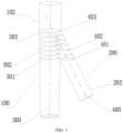
- a first blood vessel is a main branch 100 and a second blood vessel is a side branch 200.
- the main branch 100 and the side branch 200 intersect and are connected at an angle, and a distal demarcation point of the main branch 100 and the side branch 200 is a carina 500.
- a blood vessel pressure difference correction method of the side branch 200 includes the following contents: A plurality of blood vessel cross sections between a first end point and a second end point are obtained along a direction of a main branch centerline 300 by taking a proximal demarcation point of the main branch 100 and the side branch 200 as the second end point, and taking the carina 500 as the first end point.
- the blood vessel cross sections form contour lines on the main branch blood vessel wall 102 and the side branch blood vessel wall 202.
- the contour lines formed by the blood vessel cross sections on the main branch blood vessel wall 102 enclose a plurality of main convex surfaces, such as a first main convex surface 301, a third main convex surface 302, and a n th main convex surface 303 in FIG. 1 .
- the contour lines formed by the blood vessel cross sections on the side branch blood vessel wall 202 enclose a plurality of side convex surfaces, such as a first side convex surface 401, a third side convex surface 402, and a n th side convex surface 403 in FIG. 1 .
- the main cross section and the side convex surface intersect to form a plurality of intersection lines, such as a first intersection line 601, a third intersection line 602, and a n th intersection line 603 in FIG. 2 .
- intersection lines are fitted into an intersection plane, such as an intersection plane 600 as shown in FIG. 2 .
- An area of a cutting plane 700 is calculated according to the intersection plane.
- the cutting plane 700 is shown in FIG. 2 and FIG. 3 .
- the cutting plane 700 is a side branch cross section perpendicular to the side branch centerline 400 cross the carina 500.
- the area of the cutting plane 700 (an area of the intersection plane 600)*(the sine of the included angle between the main branch blood vessel centerline 300 and the side branch blood vessel centerline 400).
- the area of the cutting plane 700 is used to correct the blood vessel pressure difference.
- calculating the area of the cutting plane further includes:
- a value of the included angle ⁇ can range from 0 to 180 degrees.
- distances between the blood vessel cross sections are equal.
- the blood vessel cross section is obtained by performing scanning by an OCT probe 800 in the main branch along a direction of the main branch centerline 300.
- the OCT probe 800 passes through an intersection and connection region of the main branch and the side branch at a constant speed.
- the OCT probe 800 moves from the first end point to the second end point.
- An operation method is as follows: First, the OCT probe 800 is moved to a distal end of the main branch, then is withdrew at a constant speed, and passes through the region where the main branch and the side branch intersect, so that a plurality of images of blood vessel cross sections are obtained. In fact, the lumen diameter of the main branch blood vessel is not uniform.
- the OCT probe here can also be an IVUS probe.
- a blood vessel pressure difference correction method includes the following steps:
- the blood vessel segment includes the main branch blood vessel and the side branch blood vessel.
- the geometric parameters include a lumen area of the main branch blood vessel and a lumen area of the side branch blood vessel.
- the lumen area of the side branch blood vessel is also called an area of a cutting plane of the side branch blood vessel, and the cutting plane is the cross section of the side branch blood vessel perpendicular to the centerline of the side branch blood vessel cross the carina.
- the blood vessel segment has a plurality of side branch blood vessels, and the main branch blood vessel is divided into a plurality of blood vessel segments according to the carinas of the side branch blood vessels.
- the geometric model parameters of the blood vessel segment are embodied by the radius or diameter of the blood vessel cross section, parameters of the geometric model of the blood vessel lumen of the blood vessel segment can be calculated step by step with reference to a Murry formula, a Finet formula, a HK formula or an energy conservation model.
- geometric parameters of a lumen model of the blood vessel can be calculated with reference to the following methods.
- R 0 represents a lumen radius of a proximal end of the blood vessel
- R 1 represents a lumen radius of a distal end of the blood vessel
- C 1 represents an area of a cutting plane of the bifurcation of the proximal end of the blood vessel
- r 1 represents a radius of the cutting plane of the bifurcation of the proximal end of the blood vessel.
- an ideal lumen radius, diameter or area of the stenosis segment at the distal end of the blood vessel can be obtained by using a Murray formula of a bifurcation and shunt theorem.
- an ideal lumen radius, diameter or area of the stenosis segment of the proximal end of the blood vessel can be obtained by using by a Murray formula of a bifurcation and shunt theorem.
- the ideal lumen radius, diameter and area of the stenosis segment of the blood vessel can be calculated step by step by using the bifurcation and shunt theorem with reference to the above method.
- the geometric parameters of the lumen geometric model of the blood vessel segment in the plurality of blood vessel segments are one or a combination of the following parameters: the cross sectional area of the blood vessel lumen, the diameter of the blood vessel lumen, and the radius of the blood vessel lumen.
- the geometric parameters include a first geometric parameter that represents a cross sectional area or diameter of a distal end of the blood vessel segment; a second geometric parameter representing a cross sectional area or diameter of the first bifurcation in a range between the stenosis of the blood vessel segment and the distal end point; a third geometric parameter representing a cross sectional area or diameter of the second bifurcation in a range between the stenosis of the blood vessel segment and the distal end point; ...; a (1+n) th geometric parameter representing a cross sectional area or diameter of the n th bifurcation in a range between the stenosis of the blood vessel segment and the distal end point.
- FIG. 8 is a schematic diagram of a composition of a blood vessel pressure difference correction apparatus according to an embodiment of the present invention.
- a blood vessel pressure difference correction apparatus includes an OCT probe, a memory, an image signal processing unit, a display, and an operation input unit, and one or more processors coupled to the memory.
- the image signal processing unit is connected to the OCT probe 800 by using a feeder, and the feeder is used to provide power for a light source of the OCT probe 800, and at the same time transmit a signal of the OCT probe 800 back to the image signal processing unit.
- An output end of the image signal processing unit is connected to the processor, so that the processor obtains image data in a main branch and a side branch.
- the display is connected to the processor, and is used to display an intravascular image obtained by the OCT probe 800 and data of a cutting plane 700 obtained through calculation.
- the operation input unit is connected to the processor and is used to set operating parameters of the OCT probe 800.
- the processor is configured to execute instructions stored in the memory, and the processor performs the following operations:
- a plurality of blood vessel cross sections between a first end point and a second end point are obtained by using the OCT probe 800, along a main branch centerline 300, by taking a proximal demarcation point between a main branch 100 and a side branch 200 is the second end point, and taking a carina 500 as the first end point.
- the blood vessel cross sections form contour lines on a main blood vessel wall 102 and a side branch blood vessel wall 202.
- the contour lines formed on the main branch blood vessel wall 102 by the blood vessel cross sections enclose a plurality of main convex surfaces.
- the contour lines formed on the side branch blood vessel wall 202 by the blood vessel cross sections enclose a plurality of side convex surfaces.
- the main convex surfaces and the side convex surfaces intersect to form a plurality of intersection lines.
- the plurality of intersection lines are fitted into an intersection plane 600.
- An area of the cutting plane 700 is calculated according to the intersection plane 600.
- the area of the cutting plane 700 (an area of the intersection plane 600)*(the sine of an included angle between the centerline 300 of the main branch blood vessel and the centerline 400 of the side branch blood vessel). Then, the blood vessel pressure difference is corrected by using the area of the cutting plane 700.
- the OCT probe here can also be an IVUS probe.
- a blood vessel pressure difference correction device As shown in FIG. 9 , a blood vessel pressure difference correction device is provided.
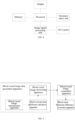
- the device includes a blood vessel image data generation apparatus, a blood vessel pressure difference calculation apparatus, and a blood vessel pressure difference correction apparatus.
- An output end of the blood vessel image data generation apparatus is respectively connected to an input end of the blood vessel pressure difference calculation apparatus and an input end of the blood vessel pressure difference correction apparatus, and the other input end of the blood vessel pressure difference correction apparatus is connected to an output end of the blood vessel pressure difference calculation apparatus.
- the blood vessel pressure difference calculation apparatus calculates a blood vessel pressure difference value after obtaining blood vessel image data from the blood vessel image data generation apparatus.
- the blood vessel pressure difference correction apparatus receives, from the blood vessel image data generation apparatus, the area data that is of the cutting plane of the side branch blood vessel in the blood vessel image and that is obtained through calculation according to the method described in Embodiment 1, and receives the blood vessel pressure difference value from the blood vessel pressure difference calculation apparatus, corrects the obtained blood vessel pressure difference value according to the area data of the cutting plane, and obtains the corrected blood vessel pressure difference value.
- the blood vessel image data generation apparatus includes a blood vessel image acquisition apparatus, a blood vessel image transmission apparatus, and a blood vessel image processing apparatus.
- An output end of the blood vessel image acquisition apparatus is sequentially connected to the blood vessel image transmission apparatus and the blood vessel image processing apparatus.
- An output end of the blood vessel image processing apparatus is respectively connected to an input end of the blood vessel pressure difference calculation apparatus and an input end of the blood vessel pressure difference correction apparatus.
- the blood vessel image data generation apparatus adopts a blood vessel lumen tomography method or an intravascular ultrasound angiography method to obtain blood vessel lumen geometric data, including using an OCT or IVUS technology.
- the blood vessel pressure difference correction apparatus can correct the blood vessel pressure difference value by using the calculation method of the geometric parameters of the blood vessel lumen (for example, the area of the cutting plane of the side branch blood vessel) involved in example 1 according to the data obtained from the blood vessel image processing apparatus.
- the blood vessel pressure difference correction apparatus described in example 3 can be used to independently obtain the geometric parameters of the blood vessel lumen (for example, the area of the cutting plane of the side branch blood vessel), and correct the blood vessel pressure difference value according to the geometric parameters.
- the program can be stored in a computer readable storage medium. When the program is executed, the procedures of the above methods may be included.
- the storage medium may be a magnetic disk, an optical disk, a read-only memory (Read-Only Memory, ROM), or a random access memory (Random Access Memory, RAM), etc.
Landscapes
- Health & Medical Sciences (AREA)
- Life Sciences & Earth Sciences (AREA)
- Engineering & Computer Science (AREA)
- Physics & Mathematics (AREA)
- Public Health (AREA)
- Medical Informatics (AREA)
- Veterinary Medicine (AREA)
- General Health & Medical Sciences (AREA)
- Animal Behavior & Ethology (AREA)
- Biophysics (AREA)
- Pathology (AREA)
- Biomedical Technology (AREA)
- Heart & Thoracic Surgery (AREA)
- Surgery (AREA)
- Molecular Biology (AREA)
- Vascular Medicine (AREA)
- Nuclear Medicine, Radiotherapy & Molecular Imaging (AREA)
- Radiology & Medical Imaging (AREA)
- Physiology (AREA)
- Cardiology (AREA)
- Theoretical Computer Science (AREA)
- General Physics & Mathematics (AREA)
- Software Systems (AREA)
- Computer Vision & Pattern Recognition (AREA)
- General Engineering & Computer Science (AREA)
- Architecture (AREA)
- Computer Graphics (AREA)
- Computer Hardware Design (AREA)
- Oral & Maxillofacial Surgery (AREA)
- Dentistry (AREA)
- Artificial Intelligence (AREA)
- Psychiatry (AREA)
- Signal Processing (AREA)
- Ultra Sonic Daignosis Equipment (AREA)
- Measuring Pulse, Heart Rate, Blood Pressure Or Blood Flow (AREA)
- Endoscopes (AREA)
- Apparatus For Radiation Diagnosis (AREA)
Description
- The present invention belongs to the field of medical technologies.
- The side-branch evaluation of a bifurcation lesion of a coronary artery has always been challenging in clinical practice and science. In a process in which this side-branch evaluation is performed by using an angiography technology, the angiography technology used involves optical coherence tomography (OCT), which is a high-resolution tomography technology and has a similar principle to intravascular ultrasound (IVUS). This technology uses near-infrared as a light source and uses interference of light waves to perform imaging. An optical signal obtained by beam scanning of a tissue is converted into an electrical signal, and the electrical signal is processed by a computer and then displayed as two-dimensional and three-dimensional images of gray or pseudo-color. Because the optical wavelength is shorter than the wavelength of sound waves, the optical coherence tomography has a higher resolution ranging from 10um to 20um. Compared with intravascular ultrasound, the optical coherence tomography can provide faster and clearer images, and more accurately display a specific shape of a blood vessel wall (whether the interior is blocked, a blocked area, a size, etc.).
US 2012/083696 A1 shows an apparatus, method and medium storing program for reconstructing intra-tubular-structure images. -
US 2015/257850 A1 discloses an image processing apparatus, which obtains a tomographic image of a tubular body by scanning an inside of a first tubular body using a probe and determine an approximating plane of boundary points between the the first and a second tubular body. Based on this, reference information for selecting a suitable device for insertion into the bifurcated tubular body is obtained.
Related to the side-branch evaluation of a bifurcation lesion of a coronary artery, the inventor of the present application disclosed a method for determining at least one geometric parameter of aside branch of a main branch of a blood vessel in thepatent document US20150238121A1 published in an earlier US patent application, and the method includes: receiving a plurality of cross-section data sets, the data sets representing geometries of cross sections of the main branch over a length of the main branch; receiving position data of a cutting plane of the main branch, the cutting plane at least partially intersecting the side branch and the cutting plane, and the cutting plane intersects the cross section at an angle; based on data in at least a part of the plurality of cross section data sets, constructing image data of a constructed cross section of the main branch in the cutting plane; receiving contour data defining a contour in the constructed cross section, the contour being provided in the side branch; and determining the geometric parameter by determining a geometric parameter of the contour. The main branch refers to a main branch blood vessel in the coronary artery, and the side branch is a side branch blood vessel connected to the main branch blood vessel. - After blood vessel geometric parameters including a blood vessel diameter or a cross sectional area are obtained, a blood vessel pressure difference can be calculated according to the blood vessel geometric parameters. The blood vessel pressure difference is a pressure difference between a proximal start point and a distal end point of a blood vessel segment of interest, and is a parameter that can effectively reflect a blood supply function of the blood vessel. Because FFR (fractional flow reserve) is approximately equal to a ratio of a distal coronary pressure Pd to a proximal coronary pressure Pa, FFR can be calculated from the blood vessel pressure difference between Pd and Pa and Pa obtained through measurement.
- The patent document
CN108022650A discloses a method for calculating a blood vessel pressure difference based on parameters of a main branch blood vessel and a side branch blood vessel. This method involves obtaining of geometric parameters of the side branch blood vessel and calculation of an ideal vessel lumen geometric model, but there is still a problem of how to correct a value of the blood vessel pressure difference in this method. - Further methods and apparatuses according to the state of the art are for instance described in
US2015/0257850A1 ,US2012/0083696A1 andCN107115108A . - An objective of the present invention is to provide a blood vessel pressure difference correction method and apparatus according to claims 1 and 4.
- The first blood vessel may be a main branch blood vessel of a coronary artery, and the second blood vessel may be a side branch blood vessel of the coronary artery.
- The apparatus is used to correct a calculation result of the blood vessel pressure difference. The apparatus includes an image imaging probe, a memory, and one or more processors coupled to the memory, and the processor is configured to execute instructions stored in the memory to perform imaging processing on image data obtained by the image imaging probe.
- A blood vessel involved in the calculation of the blood vessel pressure difference includes a first blood vessel and a second blood vessel. The first blood vessel and the second blood vessel intersect and are connected. A distal demarcation point of the first blood vessel and the second blood vessel is a carina.
- A plurality of blood vessel cross sections between a first end point and a second end point are obtained by using an image imaging probe, along a centerline of the first blood vessel, by taking the proximal demarcation point of the first blood vessel and the second blood vessel as the second end point, and taking the carina as the first end point. The processor performs the following operations:
- the blood vessel cross sections form contour lines on a first blood vessel wall and a second blood vessel wall;
- the contour lines formed on the first blood vessel wall by the blood vessel cross sections enclose a plurality of first blood convex surfaces;
- the contour lines formed on the second blood vessel wall by the blood vessel cross sections enclose a plurality of second blood vessel convex surfaces;
- the first blood convex surfaces and the second blood vessel convex surfaces intersect to form a plurality of intersection lines;
- the plurality of intersection lines are fitted into an intersection plane;
- an area of a cutting plane is calculated according to the intersection plane; and
- the blood vessel pressure difference is corrected by using the area of the cutting plane.
- An image signal processing unit is connected to an image imaging probe by using a feeder, and the feeder is used to provide power for the image imaging probe and at the same time transmit a signal of the image imaging probe back to the image signal processing unit. An output end of the image signal processing unit is connected to the processor, so that the processor obtains image data in the first blood vessel and the second blood vessel. A display is connected to the processor, and is used to display an intravascular image obtained by the image imaging probe and data of the cutting plane obtained through calculation. An operation input unit is connected to the processor and is used to set operation parameters of the image imaging probe.
- One of the beneficial effects of the embodiments of the present invention is as follows: The contour lines of a cross section of a main branch and contour lines of a convex surface of a side branch are extracted from sequence images directly obtained in the main branch blood vessel by using an OCT or IVUS image imaging probe, and sequences of intersection lines formed by intersecting the two kinds of contour lines are fitted into an intersection plane, and an area of a cutting plane of the side branch is calculated according to the intersection plane. In this way, the calculation method in the prior art is improved, an estimation error in the existing calculation method is eliminated by the correction, and calculation accuracy of the geometric parameters of the side branch is improved.
- One of the beneficial effects of the embodiments of the present invention is as follows: A geometric model of a blood vessel lumen is reconstructed by establishing blood vessel segments by using the method for calculating geometric parameters of a side branch provided in the embodiments. According to the geometric model of the blood vessel lumen, parameters of a centerline of the side branch blood vessel are extracted, a cross section of the side branch blood vessel is made on the centerline, and an area of the cross section is calculated, that is, an cutting area of the side branch blood vessel. The blood vessel pressure difference of the blood vessel segment is corrected according to the cutting area, so that accuracy of calculating fractional flow reserve FFR is improved. A blood vessel geometric parameter detection device including an image imaging probe, a memory, an image signal processing unit, a display, a processor, and an operation input unit provides cardiologists with a tool for quickly detecting and calculating geometric parameters of a side branch.
- The above and other objects, features and advantages become easier to be understood by reading the following detailed description with reference to the accompanying drawings. In the drawings, several examples are shown in an exemplary and non-limiting manner:
-
FIG. 1 is a schematic diagram of a blood vessel cross section of a main branch blood vessel and a side branch blood vessel; -
FIG. 2 is a schematic diagram of a plurality of intersection lines; -
FIG. 3 is a schematic diagram of a cutting plane. -
FIG. 4 is a lateral side view ofFIG. 1 . -
FIG. 5 is a schematic diagram of an intravascular image obtained by an OCT probe. -
FIG. 6 is a schematic diagram of intersection lines formed by main convex surfaces and side convex surfaces of blood vessel cross sections; -
FIG. 7 is a schematic diagram of a lumen model of a multi-branched blood vessel; -
FIG. 8 is a schematic diagram of a composition of a blood vessel pressure difference correction apparatus; and -
FIG. 9 is a schematic diagram of a composition of a blood vessel pressure difference correction device. - 100 main branch, 102 main branch blood vessel wall,
- 200 side branch, 202 side branch blood vessel wall,
- 300-main branch centerline, 301-first main convex surface, 302-third main convex surface, 303-nth main convex surface,
- 400-side branch centerline, 401-first side convex surface, 402-third side convex surface, 403-nth side convex surface,
- 500-carina,
- 600-intersection plane, 601-first intersection line, 602-third intersection line, 603-nth intersection line,
- 700-cutting plane,
- 800-OCT probe.
- As shown in
FIG. 1 andFIG. 4 , a first blood vessel is amain branch 100 and a second blood vessel is aside branch 200. Themain branch 100 and theside branch 200 intersect and are connected at an angle, and a distal demarcation point of themain branch 100 and theside branch 200 is acarina 500. A blood vessel pressure difference correction method of theside branch 200 includes the following contents:
A plurality of blood vessel cross sections between a first end point and a second end point are obtained along a direction of amain branch centerline 300 by taking a proximal demarcation point of themain branch 100 and theside branch 200 as the second end point, and taking thecarina 500 as the first end point. - The blood vessel cross sections form contour lines on the main branch
blood vessel wall 102 and the side branchblood vessel wall 202. - The contour lines formed by the blood vessel cross sections on the main branch
blood vessel wall 102 enclose a plurality of main convex surfaces, such as a first mainconvex surface 301, a third mainconvex surface 302, and a nth mainconvex surface 303 inFIG. 1 . - The contour lines formed by the blood vessel cross sections on the side branch
blood vessel wall 202 enclose a plurality of side convex surfaces, such as a first sideconvex surface 401, a third sideconvex surface 402, and a nth sideconvex surface 403 inFIG. 1 . - The main cross section and the side convex surface intersect to form a plurality of intersection lines, such as a
first intersection line 601, athird intersection line 602, and a nthintersection line 603 inFIG. 2 . - The plurality of intersection lines are fitted into an intersection plane, such as an
intersection plane 600 as shown inFIG. 2 . - An area of a cutting
plane 700 is calculated according to the intersection plane. The cuttingplane 700 is shown inFIG. 2 and FIG. 3 . The cuttingplane 700 is a side branch cross section perpendicular to theside branch centerline 400 cross thecarina 500. The area of the cuttingplane 700=(an area of the intersection plane 600)*(the sine of the included angle between the main branchblood vessel centerline 300 and the side branch blood vessel centerline 400). The area of the cuttingplane 700 is used to correct the blood vessel pressure difference. - According to one or more embodiments, as shown in
FIG. 1 ,FIG. 4 andFIG. 6 , in the blood vessel pressure difference correction and calculation, calculating the area of the cutting plane further includes: - identifying two points: point A and point B having the largest curvature changes on the contour line of the blood vessel cross section;
- taking a straight line segment connecting point A and point B as a boundary line between the first blood vessel and the second blood vessel;
- fitting the boundary lines formed by the plurality of blood vessel cross sections into a circular opening of the second blood vessel on the first blood vessel;
- calculating an area S0 of the circular opening;
- obtaining the included angle θ between the centerline of the first blood vessel and the centerline of the second blood vessel, and obtaining the area of the cutting plane of the second blood vessel as:

- A value of the included angle θ can range from 0 to 180 degrees.
- According to one or more embodiments, as shown in
FIG. 4 , distances between the blood vessel cross sections are equal. - According to one or more embodiments, as shown in
FIG. 5 , the blood vessel cross section is obtained by performing scanning by anOCT probe 800 in the main branch along a direction of themain branch centerline 300. TheOCT probe 800 passes through an intersection and connection region of the main branch and the side branch at a constant speed. TheOCT probe 800 moves from the first end point to the second end point. An operation method is as follows: First, theOCT probe 800 is moved to a distal end of the main branch, then is withdrew at a constant speed, and passes through the region where the main branch and the side branch intersect, so that a plurality of images of blood vessel cross sections are obtained. In fact, the lumen diameter of the main branch blood vessel is not uniform. The OCT probe here can also be an IVUS probe. - According to one or more embodiments, a blood vessel pressure difference correction method is provided, and the method includes the following steps:
- receive an intravascular tomographic image of a blood vessel segment of interest, the blood vessel segment including a proximal start point, at least one carina, and a distal end point;
- obtain a contour of a blood vessel lumen in the tomographic image through segmenting, and obtain a geometric model of the blood vessel lumen through three-dimensional reconstruction;
- extract parameters of a centerline of a side branch blood vessel according to the obtained geometric model of the blood vessel lumen;
- make a cross section perpendicular to the centerline of the side branch blood vessel cross the carina;
- calculate an area S of the side branch blood vessel on the cross section, that is, a cutting area of the side branch blood vessel; and
- correct the blood vessel pressure difference according to the cutting area of the side branch blood vessel.
- The blood vessel segment includes the main branch blood vessel and the side branch blood vessel. The geometric parameters include a lumen area of the main branch blood vessel and a lumen area of the side branch blood vessel. The lumen area of the side branch blood vessel is also called an area of a cutting plane of the side branch blood vessel, and the cutting plane is the cross section of the side branch blood vessel perpendicular to the centerline of the side branch blood vessel cross the carina.
- According to one or more embodiments, the blood vessel segment has a plurality of side branch blood vessels, and the main branch blood vessel is divided into a plurality of blood vessel segments according to the carinas of the side branch blood vessels. Assuming that the geometric model parameters of the blood vessel segment are embodied by the radius or diameter of the blood vessel cross section, parameters of the geometric model of the blood vessel lumen of the blood vessel segment can be calculated step by step with reference to a Murry formula, a Finet formula, a HK formula or an energy conservation model.
- As shown in
FIG. 7 , when there is a bifurcation in a blood vessel, a blood vessel segment between the bifurcation and a proximal start point of the blood vessel is normal, and there is stenosis in a blood vessel segment between the bifurcation and a distal end point of the blood vessel, geometric parameters of a lumen model of the blood vessel can be calculated with reference to the following methods. There is one side branch blood vessel in the blood vessel segment, and the main branch blood vessel is divided into two blood vessel segments according to the carina of the side branch blood vessel. R 0 represents a lumen radius of a proximal end of the blood vessel, and


- When the area C1 of the cutting plane of the proximal bifurcation and the normal lumen area S0 of the proximal end of the blood vessel are obtained, where


- Similarly, when there is a bifurcation in a blood vessel, there is stenosis in a blood vessel segment between the bifurcation and a proximal start point of the blood vessel, and a blood vessel segment between the bifurcation and a distal end point of the blood vessel is normal, geometric parameters of a lumen model of the blood vessel can be calculated with reference to the above similar method. When the area C1 of the cutting plane of the proximal bifurcation and the normal lumen area S1 of the distal end of the blood vessel are obtained, where


- Further, formulas such as Finet and HK of the bifurcation and shunt theorem or an energy conservation model can be used to calculate parameters such as the ideal lumen radius, diameter or area of the stenosis segment of the blood vessel. If the calculation method obtained by the Murray formula of the bifurcation and shunt theorem is taken as method (1), then:
Method (2): When the area C1 of the cutting plane of the proximal bifurcation and the area S1 of the normal lumen of the distal end of the blood vessel, where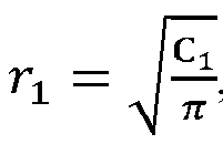


- When there is a bifurcation in the blood vessel, there is stenosis in a blood vessel segment between the bifurcation and a proximal start point of the blood vessel, and a blood vessel segment between the bifurcation and a distal end point of the blood vessel is normal, a process of calculating geometric parameters of the blood vessel lumen model includes:
When the area C1 of the cutting plane of the proximal bifurcation and the normal lumen area S1 of the distal end of the blood vessel are obtained, where


- When there is a bifurcation in the blood vessel, there is stenosis in a blood vessel segment between the bifurcation and a proximal start point of the blood vessel, and a blood vessel segment between the bifurcation and a distal end point of the blood vessel is normal, a process of calculating geometric parameters of the blood vessel lumen model includes:
When the area C1 of the cutting plane of the proximal bifurcation and the normal lumen area S1 of the distal end of the blood vessel are obtained, where


- When there is a bifurcation in the blood vessel, there is stenosis in a blood vessel segment between the bifurcation and a proximal start point of the blood vessel, and a blood vessel segment between the bifurcation and a distal end point of the blood vessel is normal, a process of calculating geometric parameters of the blood vessel lumen model includes:
When the area C1 of the cutting plane of the proximal bifurcation and the normal lumen area S1 of the distal end of the blood vessel are obtained, where


- In the above formulas (2)~(9), definitions of the parameters involved are as follows:
- R 0 represents the lumen radius of the proximal end of the blood vessel;
-


- R 1 represents the lumen radius of the distal end of the blood vessel;
-


- C1 represents the area of the cutting plane of the proximal end of the vessel; and
- r 1 represents the radius of the cutting plane of the bifurcation of the proximal end of the blood vessel.
- Further, when the blood vessel has a plurality of branches and there is stenosis in some blood vessel segments, the ideal lumen radius, diameter and area of the stenosis segment of the blood vessel can be calculated step by step by using the bifurcation and shunt theorem with reference to the above method.
- Further, the geometric parameters of the lumen geometric model of the blood vessel segment in the plurality of blood vessel segments are one or a combination of the following parameters: the cross sectional area of the blood vessel lumen, the diameter of the blood vessel lumen, and the radius of the blood vessel lumen. Considering the stenosis of the blood vessel segment, the geometric parameters include a first geometric parameter that represents a cross sectional area or diameter of a distal end of the blood vessel segment; a second geometric parameter representing a cross sectional area or diameter of the first bifurcation in a range between the stenosis of the blood vessel segment and the distal end point; a third geometric parameter representing a cross sectional area or diameter of the second bifurcation in a range between the stenosis of the blood vessel segment and the distal end point; ...; a (1+n)th geometric parameter representing a cross sectional area or diameter of the nth bifurcation in a range between the stenosis of the blood vessel segment and the distal end point.
-
FIG. 8 is a schematic diagram of a composition of a blood vessel pressure difference correction apparatus according to an embodiment of the present invention. - A blood vessel pressure difference correction apparatus is provided. The apparatus includes an OCT probe, a memory, an image signal processing unit, a display, and an operation input unit, and one or more processors coupled to the memory. The image signal processing unit is connected to the
OCT probe 800 by using a feeder, and the feeder is used to provide power for a light source of theOCT probe 800, and at the same time transmit a signal of theOCT probe 800 back to the image signal processing unit. An output end of the image signal processing unit is connected to the processor, so that the processor obtains image data in a main branch and a side branch. The display is connected to the processor, and is used to display an intravascular image obtained by theOCT probe 800 and data of a cuttingplane 700 obtained through calculation. The operation input unit is connected to the processor and is used to set operating parameters of theOCT probe 800. - The processor is configured to execute instructions stored in the memory, and the processor performs the following operations:
A plurality of blood vessel cross sections between a first end point and a second end point are obtained by using theOCT probe 800, along amain branch centerline 300, by taking a proximal demarcation point between amain branch 100 and aside branch 200 is the second end point, and taking acarina 500 as the first end point. The blood vessel cross sections form contour lines on a mainblood vessel wall 102 and a side branchblood vessel wall 202. - The contour lines formed on the main branch
blood vessel wall 102 by the blood vessel cross sections enclose a plurality of main convex surfaces. The contour lines formed on the side branchblood vessel wall 202 by the blood vessel cross sections enclose a plurality of side convex surfaces. - The main convex surfaces and the side convex surfaces intersect to form a plurality of intersection lines. The plurality of intersection lines are fitted into an
intersection plane 600. An area of the cuttingplane 700 is calculated according to theintersection plane 600. The area of the cuttingplane 700=(an area of the intersection plane 600)*(the sine of an included angle between thecenterline 300 of the main branch blood vessel and thecenterline 400 of the side branch blood vessel). Then, the blood vessel pressure difference is corrected by using the area of the cuttingplane 700. The OCT probe here can also be an IVUS probe. - As shown in
FIG. 9 , a blood vessel pressure difference correction device is provided. The device includes a blood vessel image data generation apparatus, a blood vessel pressure difference calculation apparatus, and a blood vessel pressure difference correction apparatus. - An output end of the blood vessel image data generation apparatus is respectively connected to an input end of the blood vessel pressure difference calculation apparatus and an input end of the blood vessel pressure difference correction apparatus, and the other input end of the blood vessel pressure difference correction apparatus is connected to an output end of the blood vessel pressure difference calculation apparatus.
- The blood vessel pressure difference calculation apparatus calculates a blood vessel pressure difference value after obtaining blood vessel image data from the blood vessel image data generation apparatus.
- The blood vessel pressure difference correction apparatus receives, from the blood vessel image data generation apparatus, the area data that is of the cutting plane of the side branch blood vessel in the blood vessel image and that is obtained through calculation according to the method described in Embodiment 1, and receives the blood vessel pressure difference value from the blood vessel pressure difference calculation apparatus, corrects the obtained blood vessel pressure difference value according to the area data of the cutting plane, and obtains the corrected blood vessel pressure difference value.
- Preferably, the blood vessel image data generation apparatus includes a blood vessel image acquisition apparatus, a blood vessel image transmission apparatus, and a blood vessel image processing apparatus. An output end of the blood vessel image acquisition apparatus is sequentially connected to the blood vessel image transmission apparatus and the blood vessel image processing apparatus. An output end of the blood vessel image processing apparatus is respectively connected to an input end of the blood vessel pressure difference calculation apparatus and an input end of the blood vessel pressure difference correction apparatus.
- Preferably, the blood vessel image data generation apparatus adopts a blood vessel lumen tomography method or an intravascular ultrasound angiography method to obtain blood vessel lumen geometric data, including using an OCT or IVUS technology. The blood vessel pressure difference correction apparatus can correct the blood vessel pressure difference value by using the calculation method of the geometric parameters of the blood vessel lumen (for example, the area of the cutting plane of the side branch blood vessel) involved in example 1 according to the data obtained from the blood vessel image processing apparatus. Alternatively, the blood vessel pressure difference correction apparatus described in example 3 can be used to independently obtain the geometric parameters of the blood vessel lumen (for example, the area of the cutting plane of the side branch blood vessel), and correct the blood vessel pressure difference value according to the geometric parameters.
- A person of ordinary skill in the art can understand that all or part of the processes in the above methods can be implemented by instructing relevant hardware by using a computer program. The program can be stored in a computer readable storage medium. When the program is executed, the procedures of the above methods may be included. The storage medium may be a magnetic disk, an optical disk, a read-only memory (Read-Only Memory, ROM), or a random access memory (Random Access Memory, RAM), etc.
- It is worth noting that although the foregoing content has been described with reference to several specific examples, the division of various aspects does not mean that the features in these aspects cannot be combined. This division is only for the convenience of presentation. The present invention is defined by the appended claims.
Claims (5)
- A blood vessel pressure difference correction method, wherein a blood vessel involved in the method comprises a first blood vessel (100) and a second blood vessel (200), the first blood vessel and the second blood vessel intersect and are connected, and a distal demarcation point of the first blood vessel and the second blood vessel is a carina (500), and the method comprises:Obtaining, by using images of an image imaging probe, a plurality of blood vessel cross sections between a first end point and a second end point along a direction of a centerline of the first blood vessel;characterized bytaking a proximal demarcation point of the first blood vessel and the second blood vessel as the second end point, and taking the carina as the first end point;forming, by the blood vessel cross sections, contour lines on a first blood vessel wall and a second blood vessel wall;enclosing, by the contour lines formed on the first blood vessel wall by the blood vessel cross sections, a plurality of first blood vessel convex surfaces;enclosing, by the contour lines formed on the second blood vessel wall by the blood vessel cross sections, a plurality of second blood vessel convex surfaces;intersecting, by the first blood vessel convex surfaces and the second blood vessel convex surfaces, to form a plurality of intersection lines (601, 602, 603);fitting the plurality of intersection lines into an intersection plane;calculating an area of a cutting plane (700) according to the intersection plane, wherein the cutting plane is a second blood vessel cross section perpendicular to a centerline of the second blood vessel cross the carina; andcorrecting a blood vessel pressure difference by using the area of the cutting plane.
- The blood vessel pressure difference correction method according to claim 1, wherein the calculating an area of a cutting plane further comprises:identifying two points: point A and point B having the largest curvature changes on the contour line of the blood vessel cross section;taking a straight line segment connecting point A and point B as a boundary line between the first blood vessel and the second blood vessel;fitting boundary lines formed by the plurality of blood vessel cross sections into a circular opening of the second blood vessel on the first blood vessel;calculating an area S0 of the circular opening;obtaining an included angle θ between the centerline of the first blood vessel and the centerline of the second blood vessel, and obtaining the area of the cutting plane of the second blood vessel S as:
 wherein preferably, a value range of the included angle θ is 0~180 degrees.
 - The blood vessel pressure difference correction method according to claim 1, wherein the first blood vessel is a main branch blood vessel of a coronary artery, and the second blood vessel is a side branch blood vessel of the coronary artery.
- A blood vessel pressure difference correction apparatus, configured to correct a calculation result of a blood vessel pressure difference, wherein the apparatus comprises an image imaging probe, a memory, and one or more processors coupled to the memory, and the processor is configured to execute instructions stored in the memory to perform imaging processing on the image data obtained by the image imaging probe, whereina blood vessel involved in calculation of the blood vessel pressure difference comprises a first blood vessel (100) and a second blood vessel (200), the first blood vessel and the second blood vessel intersect and are connected, and a distal demarcation point of the first blood vessel and the second blood vessel is a carina (500), anda plurality of blood vessel cross sections between a first end point and a second end point are obtained by using images of the image imaging probe, along a centerline of the first blood vessel,characterized in thata proximal demarcation point of the first blood vessel and the second blood vessel is taken as the second end point, and the carina is taken as the first end point;and that the processor is configured to perform the following operations:the blood vessel cross sections form contour lines on a first blood vessel wall and a second blood vessel wall by ;the contour lines formed on the first blood vessel wall by the blood vessel cross sections enclose a plurality of first blood convex surfaces;the contour lines formed on the second blood vessel wall by the blood vessel cross sections enclose a plurality of second blood vessel convex surfaces;the first blood convex surfaces and the second blood vessel convex surfaces intersect to form a plurality of intersection lines (601, 602, 603);the intersection lines are fitted in to an intersection plane;an area of a cutting plane (700) is calculated according to the intersection plane; andthe blood vessel pressure difference is corrected by using the area of the cutting plane.
- The blood vessel pressure difference correction apparatus according to claim 4, wherein the correction device further comprises an image signal processing unit, a display and an operation input unit,the image signal processing unit is connected to the image imaging probe by using a feeder, and the feeder is used to provide power for the image imaging probe and at the same time transmit a signal of the image imaging probe back to the image signal processing unit,an output end of the image signal processing unit is connected to the processor, so that the processor obtains image data in the first blood vessel and the second blood vessel,the display is connected to the processor, and is used to display an intravascular image obtained by the image imaging probe and data of the cutting plane obtained through calculation, andthe operation input unit is connected to the processor, and is used to set operation parameters of the image imaging probe.
Applications Claiming Priority (2)
| Application Number | Priority Date | Filing Date | Title |
|---|---|---|---|
| CN201810705804.XA CN109009001B (en) | 2018-07-02 | 2018-07-02 | Vascular pressure difference modification method, device and equipment |
| PCT/CN2018/103783 WO2020006853A1 (en) | 2018-07-02 | 2018-09-03 | Vascular pressure difference correction method, device and apparatus |
Publications (3)
| Publication Number | Publication Date |
|---|---|
| EP3818927A1 EP3818927A1 (en) | 2021-05-12 |
| EP3818927A4 EP3818927A4 (en) | 2022-03-30 |
| EP3818927B1 true EP3818927B1 (en) | 2025-06-11 |
Family
ID=65521198
Family Applications (1)
| Application Number | Title | Priority Date | Filing Date |
|---|---|---|---|
| EP18925706.6A Active EP3818927B1 (en) | 2018-07-02 | 2018-09-03 | Vascular pressure difference correction method and apparatus |
Country Status (5)
| Country | Link |
|---|---|
| US (1) | US11288811B2 (en) |
| EP (1) | EP3818927B1 (en) |
| JP (1) | JP7074952B2 (en) |
| CN (1) | CN109009001B (en) |
| WO (1) | WO2020006853A1 (en) |
Families Citing this family (15)
| Publication number | Priority date | Publication date | Assignee | Title |
|---|---|---|---|---|
| US10210956B2 (en) | 2012-10-24 | 2019-02-19 | Cathworks Ltd. | Diagnostically useful results in real time |
| EP4300419A3 (en) | 2016-05-16 | 2024-04-03 | Cathworks Ltd. | System for vascular assessment |
| IL286814B2 (en) | 2019-04-01 | 2026-03-01 | Cathworks Ltd | Methods and apparatus for angiographic image selection |
| EP4555935A3 (en) | 2019-09-23 | 2025-07-30 | Cathworks Ltd. | Methods, apparatus, and system for synchronization between a three-dimensional vascular model and an imaging device |
| EP4538970A3 (en) * | 2020-03-30 | 2025-08-27 | Terumo Kabushiki Kaisha | Computer program and information processing device |
| CN113837985B (en) * | 2020-06-24 | 2023-11-07 | 上海博动医疗科技股份有限公司 | Training method and device for angiographic image processing, automatic processing method and device |
| CN112842287B (en) * | 2021-01-05 | 2022-05-17 | 清华大学 | Device and method for measuring vascular stiffness parameters |
| US12315076B1 (en) | 2021-09-22 | 2025-05-27 | Cathworks Ltd. | Four-dimensional motion analysis of a patient's coronary arteries and myocardial wall |
| WO2023100979A1 (en) * | 2021-12-03 | 2023-06-08 | テルモ株式会社 | Information processing device, information processing method, and program |
| EP4645221A3 (en) | 2022-02-10 | 2025-12-31 | Cathworks Ltd. | SYSTEM AND METHOD FOR MACHINE LEARNING-BASED SENSOR ANALYSIS AND VASCULAR TREE SEGMENTATION |
| WO2023223087A1 (en) * | 2022-05-20 | 2023-11-23 | L&T Technology Services Limited | Non-invasive blood pressure measurement |
| CN115375749B (en) * | 2022-08-24 | 2026-01-09 | 成都全景恒升科技有限公司 | A method and system for calculating the cross-sectional area and included angle of three-dimensional blood vessel branches |
| KR20260048313A (en) | 2023-08-09 | 2026-04-09 | 캐스웍스 엘티디. | Coronary artery analysis after PCI |
| KR20260052078A (en) | 2023-08-09 | 2026-04-17 | 캐스웍스 엘티디. | Enhanced user interface and crosstalk analysis for vascular index measurement |
| US12567489B2 (en) | 2024-06-12 | 2026-03-03 | Cathworks Ltd. | Systems and methods for displaying distal fractional flow reserve values in vascular analysis |
Family Cites Families (20)
| Publication number | Priority date | Publication date | Assignee | Title |
|---|---|---|---|---|
| US8029558B2 (en) * | 2006-07-07 | 2011-10-04 | Abbott Cardiovascular Systems, Inc. | Stent and catheter assembly and method for treating bifurcations |
| US8888733B2 (en) | 2008-12-19 | 2014-11-18 | Cvdevices, Llc | Devices, systems, and methods for autoretroperfusion |
| US8934690B2 (en) * | 2009-10-28 | 2015-01-13 | Siemens Aktiengesellschaft | Method for processing vascular structure images |
| JP2012075702A (en) * | 2010-10-01 | 2012-04-19 | Fujifilm Corp | Apparatus, method, and program for reconstructing intra-tubular-structure image |
| JP5944917B2 (en) * | 2010-11-24 | 2016-07-05 | ボストン サイエンティフィック サイムド,インコーポレイテッドBoston Scientific Scimed,Inc. | Computer readable medium for detecting and displaying body lumen bifurcation and system including the same |
| WO2013019840A1 (en) | 2011-08-03 | 2013-02-07 | Lightlab Imaging, Inc. | Systems, methods and apparatus for determining a fractional flow reserve |
| JP6091870B2 (en) * | 2012-12-07 | 2017-03-08 | 東芝メディカルシステムズ株式会社 | Blood vessel analysis device, medical image diagnostic device, blood vessel analysis method, and blood vessel analysis program |
| JP6336471B2 (en) * | 2012-12-12 | 2018-06-06 | ライトラボ・イメージング・インコーポレーテッド | Method and apparatus for automated determination of vessel lumen contour |
| US9986938B2 (en) * | 2014-02-25 | 2018-06-05 | Medis Associated B.V. | Method and device for determining a geometrical parameter of a blood vessel |
| US20160374710A1 (en) * | 2014-03-12 | 2016-12-29 | Yegor D. Sinelnikov | Carotid body ablation with a transvenous ultrasound imaging and ablation catheter |
| JP6243763B2 (en) * | 2014-03-14 | 2017-12-06 | テルモ株式会社 | Image processing apparatus, method of operating image processing apparatus, and program |
| JPWO2015136853A1 (en) | 2014-03-14 | 2017-04-06 | テルモ株式会社 | Image processing apparatus, image processing method, and program |
| NL2012459B1 (en) * | 2014-03-18 | 2016-01-08 | Medis Ass B V | Method and device for determining deviation in pressure in a blood vessel. |
| US20160284080A1 (en) | 2015-03-27 | 2016-09-29 | Sabanci University | Vasculature modeling |
| US10222956B2 (en) * | 2015-05-17 | 2019-03-05 | Lightlab Imaging, Inc. | Intravascular imaging user interface systems and methods |
| US10593037B2 (en) * | 2016-04-14 | 2020-03-17 | Lightlab Imaging, Inc. | Method, apparatus, and system to identify branches of a blood vessel |
| US10231784B2 (en) * | 2016-10-28 | 2019-03-19 | Medtronic Ardian Luxembourg S.A.R.L. | Methods and systems for optimizing perivascular neuromodulation therapy using computational fluid dynamics |
| CN106650029B (en) * | 2016-11-28 | 2019-11-22 | 博动医学影像科技(上海)有限公司 | The quick calculation method and system of bifurcated vessels pressure difference and FFR based on CFD emulation |
| CN107115108B (en) * | 2017-04-27 | 2020-09-15 | 博动医学影像科技(上海)有限公司 | Method and system for rapidly calculating blood vessel pressure difference |
| CN108022650B (en) * | 2017-12-07 | 2020-11-17 | 博动医学影像科技(上海)有限公司 | Lumen modeling method and system for calculating blood vessel pressure difference |
-
2018
- 2018-07-02 CN CN201810705804.XA patent/CN109009001B/en active Active
- 2018-09-03 EP EP18925706.6A patent/EP3818927B1/en active Active
- 2018-09-03 US US17/266,253 patent/US11288811B2/en active Active
- 2018-09-03 JP JP2021507675A patent/JP7074952B2/en active Active
- 2018-09-03 WO PCT/CN2018/103783 patent/WO2020006853A1/en not_active Ceased
Also Published As
| Publication number | Publication date |
|---|---|
| EP3818927A4 (en) | 2022-03-30 |
| CN109009001A (en) | 2018-12-18 |
| WO2020006853A1 (en) | 2020-01-09 |
| EP3818927A1 (en) | 2021-05-12 |
| US11288811B2 (en) | 2022-03-29 |
| JP7074952B2 (en) | 2022-05-25 |
| US20210312636A1 (en) | 2021-10-07 |
| CN109009001B (en) | 2019-07-09 |
| JP2021531138A (en) | 2021-11-18 |
Similar Documents
| Publication | Publication Date | Title |
|---|---|---|
| US11288811B2 (en) | Vascular pressure difference correction method, device and apparatus | |
| EP3171763B1 (en) | Stent and vessel visualization and diagnostic methods | |
| US20250131567A1 (en) | Method and device for associating sets of cardiovascular data | |
| CN108022650B (en) | Lumen modeling method and system for calculating blood vessel pressure difference | |
| US7949385B2 (en) | System and method for reconstruction of the human ear canal from optical coherence tomography scans | |
| EP3723038A1 (en) | Fast calculation method and system employing plaque stability index of medical image sequence | |
| US10413317B2 (en) | System and method for catheter steering and operation | |
| US20230008714A1 (en) | Intraluminal image-based vessel diameter determination and associated devices, systems, and methods | |
| US9710891B2 (en) | Imaging apparatus for diagnosis, method of controlling the same, program, and computer-readable storage medium | |
| CN114145719B (en) | Method and system for three-dimensional fusion of dual-mode coronary vessel images | |
| US12622752B2 (en) | Self expanding stent system with imaging | |
| CN108198174A (en) | A kind of angiocarpy IVOCT and IVUS autoegistration methods and device | |
| EP3655972B1 (en) | Imaging method, controller and imaging system, for monitoring a patient post evar | |
| JP2018075080A (en) | Image diagnostic apparatus, control method for image diagnostic apparatus, and program | |
| US10159467B2 (en) | Method for seam elimination and reconstruction of coplanar images from intravascular ultrasonic data | |
| US9519840B2 (en) | Cardiovascular OCT image making method and method for detecting stents using thereof | |
| Bourantas et al. | Comparison of quantitative coronary angiography with intracoronary ultrasound. Can quantitative coronary angiography accurately estimate the severity of a luminal stenosis? | |
| EP4429562B1 (en) | Determining a flow profile in an artery based on ultrasound imaging data | |
| Zheng et al. | Measurement of Vascular Configuration Based on Fusion of Angiogram and Intravascular Ultrasound Images | |
| Shekhar et al. | Spatio-temporal localization of intravascular ultrasound data for accurate 3D reconstruction of coronary arteries | |
| Palmer et al. | Impact of Catheter Shaft Angulation on the Accuracy of Atherosclerotic Plaque Volume Measurement by Three-Dimensional Intravascular Ultrasound |
Legal Events
| Date | Code | Title | Description |
|---|---|---|---|
| STAA | Information on the status of an ep patent application or granted ep patent |
Free format text: STATUS: THE INTERNATIONAL PUBLICATION HAS BEEN MADE |
|
| PUAI | Public reference made under article 153(3) epc to a published international application that has entered the european phase |
Free format text: ORIGINAL CODE: 0009012 |
|
| STAA | Information on the status of an ep patent application or granted ep patent |
Free format text: STATUS: REQUEST FOR EXAMINATION WAS MADE |
|
| 17P | Request for examination filed |
Effective date: 20210202 |
|
| AK | Designated contracting states |
Kind code of ref document: A1 Designated state(s): AL AT BE BG CH CY CZ DE DK EE ES FI FR GB GR HR HU IE IS IT LI LT LU LV MC MK MT NL NO PL PT RO RS SE SI SK SM TR |
|
| DAV | Request for validation of the european patent (deleted) | ||
| DAX | Request for extension of the european patent (deleted) | ||
| A4 | Supplementary search report drawn up and despatched |
Effective date: 20220225 |
|
| RIC1 | Information provided on ipc code assigned before grant |
Ipc: A61B 8/04 20060101ALN20220221BHEP Ipc: A61B 8/12 20060101ALI20220221BHEP Ipc: A61B 5/107 20060101ALI20220221BHEP Ipc: A61B 5/0215 20060101AFI20220221BHEP |
|
| RAP3 | Party data changed (applicant data changed or rights of an application transferred) |
Owner name: SHANGHAI PULSE MEDICAL TECHNOLOGY INC. |
|
| STAA | Information on the status of an ep patent application or granted ep patent |
Free format text: STATUS: EXAMINATION IS IN PROGRESS |
|
| 17Q | First examination report despatched |
Effective date: 20221116 |
|
| REG | Reference to a national code |
Ref legal event code: R079 Ref country code: DE Ref legal event code: R079 Ref document number: 602018082597 Country of ref document: DE Free format text: PREVIOUS MAIN CLASS: A61B0005020000 Ipc: A61B0005021500 |
|
| GRAP | Despatch of communication of intention to grant a patent |
Free format text: ORIGINAL CODE: EPIDOSNIGR1 |
|
| STAA | Information on the status of an ep patent application or granted ep patent |
Free format text: STATUS: GRANT OF PATENT IS INTENDED |
|
| RIC1 | Information provided on ipc code assigned before grant |
Ipc: A61B 8/04 20060101ALN20241215BHEP Ipc: A61B 8/12 20060101ALI20241215BHEP Ipc: A61B 5/107 20060101ALI20241215BHEP Ipc: A61B 5/0215 20060101AFI20241215BHEP |
|
| INTG | Intention to grant announced |
Effective date: 20250103 |
|
| GRAS | Grant fee paid |
Free format text: ORIGINAL CODE: EPIDOSNIGR3 |
|
| GRAA | (expected) grant |
Free format text: ORIGINAL CODE: 0009210 |
|
| STAA | Information on the status of an ep patent application or granted ep patent |
Free format text: STATUS: THE PATENT HAS BEEN GRANTED |
|
| AK | Designated contracting states |
Kind code of ref document: B1 Designated state(s): AL AT BE BG CH CY CZ DE DK EE ES FI FR GB GR HR HU IE IS IT LI LT LU LV MC MK MT NL NO PL PT RO RS SE SI SK SM TR |
|
| P01 | Opt-out of the competence of the unified patent court (upc) registered |
Free format text: CASE NUMBER: APP_20942/2025 Effective date: 20250502 |
|
| REG | Reference to a national code |
Ref country code: GB Ref legal event code: FG4D |
|
| REG | Reference to a national code |
Ref country code: CH Ref legal event code: EP |
|
| REG | Reference to a national code |
Ref country code: IE Ref legal event code: FG4D |
|
| REG | Reference to a national code |
Ref country code: DE Ref legal event code: R096 Ref document number: 602018082597 Country of ref document: DE |
|
| PG25 | Lapsed in a contracting state [announced via postgrant information from national office to epo] |
Ref country code: FI Free format text: LAPSE BECAUSE OF FAILURE TO SUBMIT A TRANSLATION OF THE DESCRIPTION OR TO PAY THE FEE WITHIN THE PRESCRIBED TIME-LIMIT Effective date: 20250611 Ref country code: ES Free format text: LAPSE BECAUSE OF FAILURE TO SUBMIT A TRANSLATION OF THE DESCRIPTION OR TO PAY THE FEE WITHIN THE PRESCRIBED TIME-LIMIT Effective date: 20250611 |
|
| PGFP | Annual fee paid to national office [announced via postgrant information from national office to epo] |
Ref country code: DE Payment date: 20250916 Year of fee payment: 8 |
|
| REG | Reference to a national code |
Ref country code: LT Ref legal event code: MG9D |
|
| PG25 | Lapsed in a contracting state [announced via postgrant information from national office to epo] |
Ref country code: GR Free format text: LAPSE BECAUSE OF FAILURE TO SUBMIT A TRANSLATION OF THE DESCRIPTION OR TO PAY THE FEE WITHIN THE PRESCRIBED TIME-LIMIT Effective date: 20250912 Ref country code: NO Free format text: LAPSE BECAUSE OF FAILURE TO SUBMIT A TRANSLATION OF THE DESCRIPTION OR TO PAY THE FEE WITHIN THE PRESCRIBED TIME-LIMIT Effective date: 20250911 |
|
| REG | Reference to a national code |
Ref country code: NL Ref legal event code: MP Effective date: 20250611 |
|
| PG25 | Lapsed in a contracting state [announced via postgrant information from national office to epo] |
Ref country code: BG Free format text: LAPSE BECAUSE OF FAILURE TO SUBMIT A TRANSLATION OF THE DESCRIPTION OR TO PAY THE FEE WITHIN THE PRESCRIBED TIME-LIMIT Effective date: 20250611 |
|
| PGFP | Annual fee paid to national office [announced via postgrant information from national office to epo] |
Ref country code: GB Payment date: 20250919 Year of fee payment: 8 |
|
| PG25 | Lapsed in a contracting state [announced via postgrant information from national office to epo] |
Ref country code: HR Free format text: LAPSE BECAUSE OF FAILURE TO SUBMIT A TRANSLATION OF THE DESCRIPTION OR TO PAY THE FEE WITHIN THE PRESCRIBED TIME-LIMIT Effective date: 20250611 |
|
| PG25 | Lapsed in a contracting state [announced via postgrant information from national office to epo] |
Ref country code: RS Free format text: LAPSE BECAUSE OF FAILURE TO SUBMIT A TRANSLATION OF THE DESCRIPTION OR TO PAY THE FEE WITHIN THE PRESCRIBED TIME-LIMIT Effective date: 20250911 |
|
| PG25 | Lapsed in a contracting state [announced via postgrant information from national office to epo] |
Ref country code: LV Free format text: LAPSE BECAUSE OF FAILURE TO SUBMIT A TRANSLATION OF THE DESCRIPTION OR TO PAY THE FEE WITHIN THE PRESCRIBED TIME-LIMIT Effective date: 20250611 |
|
| PG25 | Lapsed in a contracting state [announced via postgrant information from national office to epo] |
Ref country code: NL Free format text: LAPSE BECAUSE OF FAILURE TO SUBMIT A TRANSLATION OF THE DESCRIPTION OR TO PAY THE FEE WITHIN THE PRESCRIBED TIME-LIMIT Effective date: 20250611 |
|
| PG25 | Lapsed in a contracting state [announced via postgrant information from national office to epo] |
Ref country code: PT Free format text: LAPSE BECAUSE OF FAILURE TO SUBMIT A TRANSLATION OF THE DESCRIPTION OR TO PAY THE FEE WITHIN THE PRESCRIBED TIME-LIMIT Effective date: 20251013 |
|
| REG | Reference to a national code |
Ref country code: AT Ref legal event code: MK05 Ref document number: 1801726 Country of ref document: AT Kind code of ref document: T Effective date: 20250611 |
|
| PG25 | Lapsed in a contracting state [announced via postgrant information from national office to epo] |
Ref country code: IS Free format text: LAPSE BECAUSE OF FAILURE TO SUBMIT A TRANSLATION OF THE DESCRIPTION OR TO PAY THE FEE WITHIN THE PRESCRIBED TIME-LIMIT Effective date: 20251011 |
|
| PG25 | Lapsed in a contracting state [announced via postgrant information from national office to epo] |
Ref country code: AT Free format text: LAPSE BECAUSE OF FAILURE TO SUBMIT A TRANSLATION OF THE DESCRIPTION OR TO PAY THE FEE WITHIN THE PRESCRIBED TIME-LIMIT Effective date: 20250611 Ref country code: SM Free format text: LAPSE BECAUSE OF FAILURE TO SUBMIT A TRANSLATION OF THE DESCRIPTION OR TO PAY THE FEE WITHIN THE PRESCRIBED TIME-LIMIT Effective date: 20250611 |
|
| PG25 | Lapsed in a contracting state [announced via postgrant information from national office to epo] |
Ref country code: CZ Free format text: LAPSE BECAUSE OF FAILURE TO SUBMIT A TRANSLATION OF THE DESCRIPTION OR TO PAY THE FEE WITHIN THE PRESCRIBED TIME-LIMIT Effective date: 20250611 |
|
| PG25 | Lapsed in a contracting state [announced via postgrant information from national office to epo] |
Ref country code: PL Free format text: LAPSE BECAUSE OF FAILURE TO SUBMIT A TRANSLATION OF THE DESCRIPTION OR TO PAY THE FEE WITHIN THE PRESCRIBED TIME-LIMIT Effective date: 20250611 |
|
| PG25 | Lapsed in a contracting state [announced via postgrant information from national office to epo] |
Ref country code: EE Free format text: LAPSE BECAUSE OF FAILURE TO SUBMIT A TRANSLATION OF THE DESCRIPTION OR TO PAY THE FEE WITHIN THE PRESCRIBED TIME-LIMIT Effective date: 20250611 |
|
| PG25 | Lapsed in a contracting state [announced via postgrant information from national office to epo] |
Ref country code: RO Free format text: LAPSE BECAUSE OF FAILURE TO SUBMIT A TRANSLATION OF THE DESCRIPTION OR TO PAY THE FEE WITHIN THE PRESCRIBED TIME-LIMIT Effective date: 20250611 Ref country code: SK Free format text: LAPSE BECAUSE OF FAILURE TO SUBMIT A TRANSLATION OF THE DESCRIPTION OR TO PAY THE FEE WITHIN THE PRESCRIBED TIME-LIMIT Effective date: 20250611 |
|
| REG | Reference to a national code |
Ref country code: DE Ref legal event code: R097 Ref document number: 602018082597 Country of ref document: DE |
|
| PG25 | Lapsed in a contracting state [announced via postgrant information from national office to epo] |
Ref country code: DK Free format text: LAPSE BECAUSE OF FAILURE TO SUBMIT A TRANSLATION OF THE DESCRIPTION OR TO PAY THE FEE WITHIN THE PRESCRIBED TIME-LIMIT Effective date: 20250611 |
|
| PG25 | Lapsed in a contracting state [announced via postgrant information from national office to epo] |
Ref country code: IT Free format text: LAPSE BECAUSE OF FAILURE TO SUBMIT A TRANSLATION OF THE DESCRIPTION OR TO PAY THE FEE WITHIN THE PRESCRIBED TIME-LIMIT Effective date: 20250611 |
|
| PLBE | No opposition filed within time limit |
Free format text: ORIGINAL CODE: 0009261 |
|
| STAA | Information on the status of an ep patent application or granted ep patent |
Free format text: STATUS: NO OPPOSITION FILED WITHIN TIME LIMIT |
|
| REG | Reference to a national code |
Ref country code: CH Ref legal event code: L10 Free format text: ST27 STATUS EVENT CODE: U-0-0-L10-L00 (AS PROVIDED BY THE NATIONAL OFFICE) Effective date: 20260423 |
|
| REG | Reference to a national code |
Ref country code: CH Ref legal event code: H13 Free format text: ST27 STATUS EVENT CODE: U-0-0-H10-H13 (AS PROVIDED BY THE NATIONAL OFFICE) Effective date: 20260504 |