EP3818926A1 - Medical illuminator with variable polarization - Google Patents
Medical illuminator with variable polarization Download PDFInfo
- Publication number
- EP3818926A1 EP3818926A1 EP20206915.9A EP20206915A EP3818926A1 EP 3818926 A1 EP3818926 A1 EP 3818926A1 EP 20206915 A EP20206915 A EP 20206915A EP 3818926 A1 EP3818926 A1 EP 3818926A1
- Authority
- EP
- European Patent Office
- Prior art keywords
- leds
- illumination device
- light
- sets
- dial
- Prior art date
- Legal status (The legal status is an assumption and is not a legal conclusion. Google has not performed a legal analysis and makes no representation as to the accuracy of the status listed.)
- Granted
Links
Images







Classifications
-
- A—HUMAN NECESSITIES
- A61—MEDICAL OR VETERINARY SCIENCE; HYGIENE
- A61B—DIAGNOSIS; SURGERY; IDENTIFICATION
- A61B5/00—Measuring for diagnostic purposes; Identification of persons
- A61B5/0059—Measuring for diagnostic purposes; Identification of persons using light, e.g. diagnosis by transillumination, diascopy, fluorescence
-
- A—HUMAN NECESSITIES
- A61—MEDICAL OR VETERINARY SCIENCE; HYGIENE
- A61B—DIAGNOSIS; SURGERY; IDENTIFICATION
- A61B5/00—Measuring for diagnostic purposes; Identification of persons
- A61B5/0059—Measuring for diagnostic purposes; Identification of persons using light, e.g. diagnosis by transillumination, diascopy, fluorescence
- A61B5/0077—Devices for viewing the surface of the body, e.g. camera, magnifying lens
-
- A—HUMAN NECESSITIES
- A61—MEDICAL OR VETERINARY SCIENCE; HYGIENE
- A61B—DIAGNOSIS; SURGERY; IDENTIFICATION
- A61B5/00—Measuring for diagnostic purposes; Identification of persons
- A61B5/0059—Measuring for diagnostic purposes; Identification of persons using light, e.g. diagnosis by transillumination, diascopy, fluorescence
- A61B5/0062—Arrangements for scanning
- A61B5/0064—Body surface scanning
-
- A—HUMAN NECESSITIES
- A61—MEDICAL OR VETERINARY SCIENCE; HYGIENE
- A61B—DIAGNOSIS; SURGERY; IDENTIFICATION
- A61B5/00—Measuring for diagnostic purposes; Identification of persons
- A61B5/103—Measuring devices for testing the shape, pattern, colour, size or movement of the body or parts thereof, for diagnostic purposes
- A61B5/1032—Determining colour of tissue for diagnostic purposes
-
- A—HUMAN NECESSITIES
- A61—MEDICAL OR VETERINARY SCIENCE; HYGIENE
- A61B—DIAGNOSIS; SURGERY; IDENTIFICATION
- A61B5/00—Measuring for diagnostic purposes; Identification of persons
- A61B5/44—Detecting, measuring or recording for evaluating the integumentary system, e.g. skin, hair or nails
- A61B5/441—Skin evaluation, e.g. for skin disorder diagnosis
-
- A—HUMAN NECESSITIES
- A61—MEDICAL OR VETERINARY SCIENCE; HYGIENE
- A61B—DIAGNOSIS; SURGERY; IDENTIFICATION
- A61B90/00—Instruments, implements or accessories specially adapted for surgery or diagnosis and not covered by any of the groups A61B1/00 - A61B50/00, e.g. for luxation treatment or for protecting wound edges
- A61B90/36—Image-producing devices or illumination devices not otherwise provided for
-
- F—MECHANICAL ENGINEERING; LIGHTING; HEATING; WEAPONS; BLASTING
- F21—LIGHTING
- F21V—FUNCTIONAL FEATURES OR DETAILS OF LIGHTING DEVICES OR SYSTEMS THEREOF; STRUCTURAL COMBINATIONS OF LIGHTING DEVICES WITH OTHER ARTICLES, NOT OTHERWISE PROVIDED FOR
- F21V23/00—Arrangement of electric circuit elements in or on lighting devices
- F21V23/04—Arrangement of electric circuit elements in or on lighting devices the elements being switches
-
- F—MECHANICAL ENGINEERING; LIGHTING; HEATING; WEAPONS; BLASTING
- F21—LIGHTING
- F21V—FUNCTIONAL FEATURES OR DETAILS OF LIGHTING DEVICES OR SYSTEMS THEREOF; STRUCTURAL COMBINATIONS OF LIGHTING DEVICES WITH OTHER ARTICLES, NOT OTHERWISE PROVIDED FOR
- F21V9/00—Elements for modifying spectral properties, polarisation or intensity of the light emitted, e.g. filters
- F21V9/14—Elements for modifying spectral properties, polarisation or intensity of the light emitted, e.g. filters for producing polarised light
-
- G—PHYSICS
- G02—OPTICS
- G02B—OPTICAL ELEMENTS, SYSTEMS OR APPARATUS
- G02B25/00—Eyepieces; Magnifying glasses
- G02B25/002—Magnifying glasses
-
- G—PHYSICS
- G02—OPTICS
- G02B—OPTICAL ELEMENTS, SYSTEMS OR APPARATUS
- G02B25/00—Eyepieces; Magnifying glasses
- G02B25/002—Magnifying glasses
- G02B25/007—Magnifying glasses comprising other optical elements than lenses
-
- G—PHYSICS
- G02—OPTICS
- G02B—OPTICAL ELEMENTS, SYSTEMS OR APPARATUS
- G02B25/00—Eyepieces; Magnifying glasses
- G02B25/002—Magnifying glasses
- G02B25/008—Magnifying glasses comprising two or more lenses
-
- G—PHYSICS
- G02—OPTICS
- G02B—OPTICAL ELEMENTS, SYSTEMS OR APPARATUS
- G02B25/00—Eyepieces; Magnifying glasses
- G02B25/02—Eyepieces; Magnifying glasses with means for illuminating object viewed
-
- G—PHYSICS
- G02—OPTICS
- G02B—OPTICAL ELEMENTS, SYSTEMS OR APPARATUS
- G02B5/00—Optical elements other than lenses
- G02B5/30—Polarising elements
- G02B5/3025—Polarisers, i.e. arrangements capable of producing a definite output polarisation state from an unpolarised input state
-
- H—ELECTRICITY
- H05—ELECTRIC TECHNIQUES NOT OTHERWISE PROVIDED FOR
- H05B—ELECTRIC HEATING; ELECTRIC LIGHT SOURCES NOT OTHERWISE PROVIDED FOR; CIRCUIT ARRANGEMENTS FOR ELECTRIC LIGHT SOURCES, IN GENERAL
- H05B45/00—Circuit arrangements for operating light-emitting diodes [LED]
- H05B45/30—Driver circuits
- H05B45/32—Pulse-control circuits
- H05B45/325—Pulse-width modulation [PWM]
-
- A—HUMAN NECESSITIES
- A61—MEDICAL OR VETERINARY SCIENCE; HYGIENE
- A61B—DIAGNOSIS; SURGERY; IDENTIFICATION
- A61B90/00—Instruments, implements or accessories specially adapted for surgery or diagnosis and not covered by any of the groups A61B1/00 - A61B50/00, e.g. for luxation treatment or for protecting wound edges
- A61B90/36—Image-producing devices or illumination devices not otherwise provided for
- A61B90/361—Image-producing devices, e.g. surgical cameras
- A61B2090/3616—Magnifying glass
-
- F—MECHANICAL ENGINEERING; LIGHTING; HEATING; WEAPONS; BLASTING
- F21—LIGHTING
- F21Y—INDEXING SCHEME ASSOCIATED WITH SUBCLASSES F21K, F21L, F21S and F21V, RELATING TO THE FORM OR THE KIND OF THE LIGHT SOURCES OR OF THE COLOUR OF THE LIGHT EMITTED
- F21Y2115/00—Light-generating elements of semiconductor light sources
- F21Y2115/10—Light-emitting diodes [LED]
-
- G—PHYSICS
- G02—OPTICS
- G02B—OPTICAL ELEMENTS, SYSTEMS OR APPARATUS
- G02B7/00—Mountings, adjusting means, or light-tight connections, for optical elements
- G02B7/02—Mountings, adjusting means, or light-tight connections, for optical elements for lenses
Definitions
- the present disclosure relates generally to a hand-held illumination device used in medical examinations. More particularly, the present disclosure relates to an improved apparatus for enhanced viewing and illumination for medical examinations using cross-polarized and parallel-polarized light to aid in viewing internal structures as well as the skin surface.
- Hand-held illuminators without magnification include pen lights, which are widely used by general medical practitioners.
- physicians and medical practitioners make use of hand-held illumination devices that have magnification including otoscopes, ophthalmoscopes and dermatoscopes.
- Typical otoscopes, ophthalmoscopes and dermatoscopes include a single lens for magnification and are designed for particular types of examination.
- a device that uses two magnification viewing lenses each having different powered magnification is described in United States Patent No. 10,441,379, issued on October 15, 2019 to Mullani entitled Multipurpose Medical Illuminator with Magnification, the substance of which is wholly incorporated herein by reference.
- Hand-held dermoscopy devices that use light with magnification can utilize polarizers or liquid-glass interfaces to reduce surface reflection and aid in viewing of deeper structures in the skin.
- the DermLite® Platinum® product manufactured by 3Gen, LLC, was developed to provide variable polarization. Variable polarization is achieved by a rotating dial. Rotation of the polarizer to a cross-polarization orientation cancels out the surface reflection for an in-depth look at the deeper pigmentation in lesion structure. Rotation to a parallel polarization orientation allows a clear view of the skin surface.
- the DermLite® Platinum® product requires manual manipulation of the dial which may cause the user to lose the viewing spot, or otherwise interfere with examination.
- a dermoscopy device identified as the Dermlite® DL3 device is manufactured and marketed by 3Gen, Inc. of San Juan Capistrano, CA which uses light and polarization.
- a series of light emitting diodes (“LEDs") are concentrically positioned around a magnifying lens to assist in lighting of a magnified image.
- the device includes LEDs that provide reduced glare and cross-polarized light to aid in canceling the reflected light from the skin, and other LEDs on the device provide non-polarized light for traditional immersion fluid dermoscopy or for simply employing non-polarized light.
- the 7,027,153 and 7,167,244 references suggest the use of LEDs with 480nm, 580nm and 660nm wavelengths.
- a dermoscopy device identified as the Dermlite ® II Multispectral dermoscopy device manufactured and marketed by 3Gen, Inc. of San Juan Capistrano, CA provides four sets of LED's comprising white, blue light (470nm) for surface pigmentation, yellow light (580nm) for superficial vascularity viewing, and red light (660nm) for viewing of pigmentation and vascularity with the deeper-penetrating red light frequency.
- Dermotoscopes using coloured LEDs to augment the viewing of pigmentation of human tissue including skin are shown and described in United States Patent No. 9,458,990, issued October 4, 2016 to Mullani entitled Dermoscopy Illumination Device With Selective Polarization And Orange Light For Enhanced Viewing of Pigmented Tissue, the substance of which is wholly incorporated herein by reference.
- a dermoscopy device identified as the Dermlite® DL4 dermoscopy device manufactured and marketed by 3Gen, Inc. of San Juan Capistrano, CA provides combinations of white LED lights and orange LED lights in both polarized and non-polarized combinations to provide enhanced viewing of skin pigmentation.
- hand-held medical illuminators have been used to introduce light into human tissue for observing sub-dermal structures using side-transillumination techniques whereby the light source is caused to be in direct contact with the skin to transfer light directly into the skin.
- side-transillumination techniques whereby the light source is caused to be in direct contact with the skin to transfer light directly into the skin.
- One such technique is known and taught in United States Patent No. 5,146,923, issued on September 15, 1992 to Dhawan entitled Apparatus And Method For Skin Lesion Examination, the substance of which is wholly incorporated herein by reference.
- a combination of a surface illumination, epiluminescence and transillumination apparatus and method is demonstrated in the NevoscopeTM product manufactured by Translite LLC of Sugar Land, TX.
- Another known apparatus and method of viewing vein structures beneath the skin employs the use of transillumination as described in United States Patent No.
- the present disclosure contemplates various devices for overcoming the above drawbacks accompanying the known art.
- One aspect of the embodiments of the present disclosure is an illumination device for illuminating organic tissue such as a patient's skin.
- the illumination device may include a first set of one or more light emitting diodes (LEDs), a first polarizer arranged to polarize light emitted from the first set of one or more LEDs in a first polarization direction or first polarization state, a second set of one or more LEDs, a second polarizer arranged to polarize light emitted from the second set of one or more LEDs in a second polarization direction or second polarization state, a lens arranged to collect light from organic tissue illuminated by either one or both of the first and second sets of one or more LEDs, a viewing polarizer arranged to polarize the light collected from the organic tissue in the second polarization direction or second polarization state, a pulse generator operable to generate a pulsed voltage having an adjustable pulse width
- a further embodiment of the disclosed device relates to is an illumination device for illuminating organic tissue such as a patient's skin.
- the illumination device may include a first set of one or more light emitting diodes (LEDs), a first polarizer arranged to polarize light emitted from the first set of one or more LEDs in a first polarization direction or first polarization state, a second set of one or more LEDs, a second polarizer arranged to polarize light emitted from the second set of one or more LEDs in a second polarization direction or second polarization state, a lens arranged to collect light from organic tissue illuminated by either one or both of the first and second sets of one or more LEDs, a viewing polarizer arranged to polarize the light collected from the organic tissue in the second polarization direction or second polarization state.
- LEDs light emitting diodes
- first polarizer arranged to polarize light emitted from the first set of one or more LEDs in a first polar
- a microprocessor for receiving a user input signal to drive one or more drivers for driving one of the first and second sets of one or more LEDs according to a predetermined ratio for setting the light intensity of the first and second sets of LEDs to achieve variable polarization without the need to mechanically rotate a polarizer.
- a dial is provided to adjust the light intensity, wherein the movement of the dial is detected by an optical encoder and the optical encoder transmits a signal related to the detected movement of the dial to a microprocessor to determine the light intensity for the first and second sets of one or more LEDs.
- the present disclosure encompasses various devices for illuminating organic tissue such as a person's skin.
- the detailed description set forth below in connection with the appended drawings is intended as a description of several currently contemplated embodiments. It is not intended to represent the only form in which the disclosed subject matter may be developed or utilized.
- the description sets forth the functions and features in connection with the illustrated embodiments. It is to be understood, however, that the same or equivalent functions may be accomplished by different embodiments that are also intended to be encompassed within the scope of the present disclosure. It is further understood that the use of relational terms such as first and second and the like are used solely to distinguish one from another entity without necessarily requiring or implying any actual such relationship or order between such entities.
- the numbers expressing dimensions, quantities, quantiles of ingredients, properties of materials, and so forth, used to describe and claim certain embodiments of the disclosure are to be understood as being modified in some instances by the term "about.” Accordingly, in some embodiments, the numerical parameters set forth in the written description and attached claims are approximations that can vary depending upon the desired properties sought to be obtained by a particular embodiment. In some embodiments, the numerical parameters should be construed in light of the number of reported significant digits and by applying ordinary rounding techniques. Notwithstanding that the numerical ranges and parameters setting forth the broad scope of some embodiments of the disclosure are approximations, the numerical values set forth in the specific examples are reported as precisely as practicable. The numerical values presented in some embodiments of the disclose may contain certain errors necessarily resulting from the standard deviation found in their respective testing measurements.
- Coupled to is intended to include both direct coupling (in which two elements that are coupled to each other contact each other) and indirect coupling (in which at least one additional element is located between the two elements). Therefore, the terms “coupled to” and “coupled with” are used synonymously.
- inventive subject matter provides many example embodiments of the inventive subject matter. Although each embodiment represents a single combination of inventive elements, the inventive subject matter is considered to include all possible combinations of the disclosed elements. Thus if one embodiment comprises elements A, B, and C, and a second embodiment comprises elements B and D, then the inventive subject matter is also considered to include other remaining combinations of A, B, C, or D, even if not explicitly disclosed.
- inventive subject matter is also considered to include other remaining combinations of A, B, C, or D, even if not explicitly disclosed.
- any language herein directed to a computer or computing devices should be read to include any suitable combination of computing devices, including servers, interfaces, systems, databases, agents, peers, engines, controllers, modules, or other types of computing devices operating individually or collectively.
- the computing devices comprise at least one processor configured to execute a computer program product comprising software instructions stored on a tangible, non-transitory computer readable storage medium (e.g., hard drive, FPGA, PLA, solid state drive, RAM, flash, ROM, etc .).
- the software instructions configure or program the computing device to provide the roles, responsibilities, or other functionality as discussed with respect to the disclosed devices.
- the disclosed technologies can be embodied as a computer program product that includes a non-transitory computer readable medium storing the software instructions that causes a processor to execute the disclosed steps associated with implementations of computer-based algorithms, processes, methods, or other instructions.
- the various servers, systems, databases, or interfaces exchange data using standardized protocols or algorithms, possibly based on HTTP, HTTPS, TCP/IP, UPD/IP, AES, public-private key exchanges, web service APIs, known financial transaction protocols, or other electronic information exchanging methods.
- Data exchanges among devices can be conducted over a packet-switched network, the Internet, LAN, WAN, VPN, or other type of packet switched network; a circuit switched network; cell switched network; or other type of network.
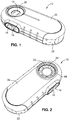
- FIG. 1 shows the top perspective view of the device 12 showing the viewing port of an optical lens 14 incorporated into a housing 20.
- a battery cover 22 may be removably secured to the housing 20 to provide access to an interior compartment for insertion and removal of a battery.
- a light portal may be incorporated into the housing 20 to expose a viewing polarizer 24.
- a plurality of light emitting diodes may encircle the viewing polarizer within the housing 20 and direct light though a multiple layer filter ring 25 in order to selectively illuminate the surface of the organic tissue with cross-polarized and parallel-polarized light.
- switches 16, 18 a user of the device 12 can control the relative portion of cross-polarized light and parallel-polarized light by pulse width modulation, thus selectively increasing and decreasing the effective penetration depth of the view.
- a switch 16 for increasing the effective penetration depth and a switch 18 for decreasing the effective penetration depth may be provided as momentary up and momentary down positions of a usually neutral rocker switch as shown.
- the switches 16, 18 may be individual push buttons, touchscreen elements, opposing inputs of a slider, dial, or knob, etc.
- FIG 3 is an exploded top view of the device 12 and Figure 4 is an exploded bottom view of the device 12.
- the housing 20 may include a top component 20a and bottom component 20b.
- the top component 20a, bottom component 20b, and battery cover 22 may be formed from molded lightweight durable plastic.
- the plastic may be a PVC derivative material and may be formed from acrylic or lexan.
- the housing may be formed from metal such as aluminum.
- Components 20a, 20b and cover 22 may be interconnected to form the outer housing 20 as shown in Figures 1 and 2 .
- the top housing component 20a may include an aperture 26 for receiving the combination of the optical lens 14 inserted within a lens sleeve 28. Shown best in Figure 4 , the underside of the top housing component 20a is shown wherein the aperture 26 incorporates a downwardly protruding (upwardly in Figure 4 ) collar 30 for receiving the lens 14 within the lens sleeve 28.
- the lens sleeve 28 may incorporate an annular lip 29 which engages sloped sides of the aperture 26 to complete the exterior of the viewing port of the housing 20.
- the lens sleeve 28 may operate to securely hold the lens 14 in place within the aperture 26.
- the lens 14 is preferably a 15mm diameter Hastings lens with a 10 X optical gain.
- the lens may be a single convex lens, a combination of two or more lenses, a double achromat lens, or a combination of double achromat lenses.
- the lens may incorporate aspherical lenses to accommodate better optics and lower distortion. Lenses coated with an antireflection coating may be used and a color filter may additionally be included to selectively filter light passing through the lens.
- the protruding collar 30 may be part of the unitary structure of the upper housing component 20a.
- the collar 30, which may be cylindrical, may protrude through the interior components of the housing 20, including a printed circuit board (PCB) 32 having an opening 33, to extend to the light portal of the bottom component 20b.
- a battery 34 may nest within a battery chamber formed by the top component 20a and bottom component 20b.
- the PCB 32 may include electrical contacts 36a and 36b for interfacing with battery contacts 38a and 38b.
- the upper housing 20a may include slots 40a and 40b to allow the PCB contacts 36a and 36b to protrude from the circuit board 32 into the battery chamber and contact the battery leads 38a and 38b.
- the battery 34 may be an extended charge lithium battery.
- the battery could be any suitable battery package such as a one-time lithium battery or rechargeable lithium battery.
- the disclosure additionally contemplates use of a DC power supply or an external power supply through a wire through contacts or a power port such as a USB or USB-C port.
- the bottom component 20b may include a viewing aperture 42 aligned with the aperture 26 of the top component 20a.
- the viewing polarizer 24 inserted within a sleeve 44 may cap off the opening of the collar 30.
- the viewing polarizer 24 may be composed of acrylic plastic with polarization material embedded within the polarizer. It is contemplated that the viewing polarizer 24 may alternatively be constructed of glass, with polarization material embedded or coated on the glass. In addition, the viewing polarizer 24 may be coated with a filter material that can selectively filter out some of the light frequencies emanating from the object. Alternatively, a secondary filter assembly made of plastic or glass with the capability of filtering the light may be placed in the path of the viewing lens 14 to filter out some of the light.
- the bottom housing component 20b may include a bottom collar 46 formed therein.
- a lip 48 incorporating a plurality of guide tabs may be formed between the collar 46 and the viewing aperture 42.
- the lip 48 and guide tabs may be adapted to engage a bottom annular polarizer 50 and a top annular polarizer 52.
- the top 52 and bottom 50 polarizers may have different polarization directions and may, for example, be 90 degrees out of phase.
- the bottom 50 polarizer may be in cross polarization with the viewing polarizer 24, and the top polarizer 52 may be in parallel polarization with the viewing polarizer 24.
- the top 52 and bottom 50 polarizers may be composed of acrylic plastic and may include polarization at different angles.
- the polarizers 50 and 52 may also be coated with a special material to filter out some of the light emanating from the LEDs, or alternatively the annular polarizer 50 and 52 may be sandwiched with a color filter acrylic material.
- the viewing aperture 42 may be wide enough to permit a viewing corridor from the lens sleeve 28 through the housing 20 to the viewing aperture 42 while allowing portions of the top 52 and bottom 50 polarizers to be exposed and to filter light emitting diodes inside the housing 20.
- sixteen light emitting diodes 58 ring the circuit board 32, though it is contemplated that the number of diodes may be greater or less.
- the diodes 58 are preferably white high light output Indium Gallium Nitride LEDs, but any suitable lighting diodes are appropriate. Every other diode 58 may be on the same circuit, for example, the even diodes may be on a single circuit and the odd diodes may be on a separate single circuit.
- the LEDs 58 are a standard white LED made with phosphorescence phosphors to create white light. It is additionally contemplated by the present disclosure that tri-colored LEDs, with individual red, green and blue LEDs that can combine to form white light, may be utilized. It is contemplated by the present disclosure that the LEDs may have focusing lenses to concentrate the light into a smaller and tighter beam.
- the LEDs may additionally be comprised of indium gallium arsenide material, or any other like semiconductor material.
- the PCB 32 may additionally incorporate an integrated circuit 74 for selectively driving the LEDs 58.
- the integrated circuit 74 may be electrically connected to the switches 16, 18 and the battery 34 via the PCB 32.
- the integrated circuit 74 may additionally be communicatively coupled to an external device (e.g. a smartphone or other mobile device) via radio frequency transmission according to any of various wireless communication protocols such as Bluetooth.
- an external device e.g. a smartphone or other mobile device
- a user may selectively drive the LEDs 58 as described in more detail below in order to increase or decrease the effective penetration depth when viewing organic tissue using the device 12.
- the first polarizer filter 50 may comprise a planar annular ring defining a generally circular center opening and an outer ring.
- the center opening of the annular ring of the first polarizer 50 may be positioned in alignment with the circular optical lens 14 to provide an unobstructed view of the organic tissue through the lens 14 and the housing 20.
- the outer ring of the first polarizer 50 may be arranged to polarize light emitted from a first set of one or more LEDs 58 (e.g. the even diodes) in a first polarization direction and to include a plurality of openings sized and positioned to correspond to the diodes 58 of a second set of one or more LEDs 58 (e.g. the odd diodes).
- the second polarizer filter 52 may likewise comprise a planar annular ring defining a generally circular center opening and an outer ring, with the center opening of said annular ring of the second polarizer 52 positioned in alignment with the circular optical lens 14 to provide an unobstructed view of the organic tissue through the lens 14 and housing 20.
- the second polarizer 52 may be 90 degrees out of phase with the first polarizer 50 as noted above.
- the outer ring of the second polarizer 52 may be arranged to polarize light emitted from the second set of one or more LEDs 58 (e.g.
- the second polarizer 52 may have a plurality of openings, but in the case of the second polarizer 52 the plurality of openings may be sized and positioned to correspond to the diodes 58 of the first set of one or more LEDs 58 (e.g. the even diodes). Thus, the light emitted from the first set of one or more LEDs 58 may pass through the openings unfiltered by the second polarizer 52.
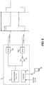
- Figure 5 is a schematic view of the device 12 showing circuit components for operating the device 12.
- the components shown in Figure 5 are depicted as being components of the integrated circuit 74 ( see Figure 4 ), which may be a microcontroller for example.
- the device 12 may include a pulse generator 76, an inverter 78, a first driver 80a, a second driver 80b, and a controller 82.
- the pulse generator 76 may be operable to generate a pulsed voltage having an adjustable pulse width p for driving one or both of the first and second sets of LEDs 58 at a frequency f.
- the first driver 80a may drive the first set of one or more LEDs 58 (e.g. the even diodes).
- the pulse of width p may represent a portion of a period 1/f during which the even diodes are turned on, such that reducing the pulse width p causes the even diodes to dim as perceived by the human eye or by a camera with a frame rate or shutter speed less than the frequency f.
- the second driver 80b may drive the second set of one or more LEDs 58 (e.g. the odd diodes).
- the inverse pulse width (1-p) may represent a portion of a period 1/f during which the odd diodes are turned on, such that reducing the pulse width p causes the odd diodes to brighten as the even diodes dim.
- the same total power may be used to drive the LEDs 58 irrespective of the pulse width p, with the even and odd diodes 58 being oppositely brightened and dimmed according to the setting of the pulse width p.
- Operation of the pulse generator 76 may be controlled by the controller 82 in response to user inputs made using the switches 16, 18 ( see Figure 1 etc.).
- the switch 16 may increase the effective penetration depth when viewing organic tissue using the device 12 and the switch 18 may decrease the effective penetration depth.
- the controller 82 may increase the pulse width p in response to a user pressing the switch 16 and may decrease the pulse width p in response to a user pressing the switch 18.
- the first set of one or more LEDs 58 e.g. the even diodes
- the first polarized in the first polarization direction by the first polarizer 50 are driven for a greater portion of each cycle 1/f.
- the viewing polarizer 24 With the viewing polarizer 24 being cross polarized relative to the first polarization direction, the reflected light of the first LEDs 58 off the outermost layers of the organic tissue is blocked by the viewing polarizer 24. Meanwhile, the reflected light of the first LEDs 58 from deeper layers of the organic tissue will have a shifted polarization due to refraction and will thus be at least partially transmitted by the viewing polarizer 24. As a result, driving the first set of LEDs 58 (e.g. the even diodes) for a greater portion of each cycle may have the effect of increasing the effective penetration depth when viewing the organic tissue, thus deemphasizing surface features.
- driving the first set of LEDs 58 e.g. the even diodes
- the second set of LEDs 58 (e.g. the odd diodes), which are polarized in the second polarization direction by the second polarizer 52.
- the viewing polarizer 24 sharing the second polarization direction of the light of the second LEDs 58, the reflected light of the first LEDs 58 off the outermost layers of the organic tissue is polarized parallel to the viewing polarizer 24 and thus transmitted.
- the reflected light of the first LEDs 58 from deeper layers of the organic tissue will have a shifted polarization due to refraction and will thus be at least partially blocked by the viewing polarizer 24.
- driving the second set of LEDs 58 (e.g. the odd diodes) for a greater portion of each cycle may have the effect of decreasing the effective penetration depth when viewing the organic tissue, thus emphasizing surface features.
- the switch 16 is pressed repeatedly until the pulse width p is set to 0%, the first set of LEDs 58 (even diodes) are off for the entire cycle while the second set of LEDs 58 (odd diodes) are on, resulting in parallel polarization of surface reflections and a minimum effective penetration depth.
- user inputs to the controller 82 may alternatively or additionally be made using an external device 84 (e.g. a smartphone or other mobile device) via wireless communication (e.g. Bluetooth).
- an external device 84 e.g. a smartphone or other mobile device
- wireless communication e.g. Bluetooth
- the external device 84 may run a mobile application (e.g. a downloadable "app") that establishes a wireless connection with the controller 82 and generates a graphical user interface for adjusting settings of the pulse generator 76.
- a graphical user interface may include, for example, virtual sliders, buttons, etc. having the functions of the switches 16, 18 shown in Figure 1 for controlling the pulse width p.
- Additional functionality of the graphical user interface may include, for example, adjusting the frequency f of the pulsed voltage (e.g. from 100 to 10,000,000 Hz), adjusting the forward current of the LED (e.g. by controlling the drivers 80a, 80b) to allow analog control of the intensity of light, changing the mode of operation of the device 12 (e.g. to turn off the pulse generator 76 entirely and allow for static operation of the first and/or second sets of LEDs 58), and/or communicating with a camera of the external device 84 to capture an image of the organic tissue.
- the device 12 may be attachable to the external device 84 (e.g.
- a three-dimensional map of the organic tissue may be constructed by combining images taken at a plurality of effective penetration depths.
- every other LED 58 is on the same circuit, with the even diodes on one circuit and the odd diodes on another circuit. That is, the LEDs 58 are grouped into two sets, each corresponding to its own polarizer 50, 52. However, the disclosure is not intended to be so limited, and greater numbers of sets of LEDs 58 are contemplated as well.
- a third set of LEDs 58 may be provided that emit light that is neither polarized by the bottom polarizer 50 nor by the top polarizer 52 and instead remains non-polarized (e.g. by passing through corresponding holes in both polarizers 50, 52).
- a fourth set of LEDs 58 may be provided that similarly emit non-polarized light but at an ultraviolet wavelength or another wavelength (e.g. blue).
- the LEDs 58 may be arranged in a single ring such that one out of every four LEDs 58 is on the same circuit.
- the first and second sets of LEDs 58 may be driven in response to the output of the pulse generator 76 as shown in Figure 5 , with the third and fourth sets of LEDs 58 being independently controlled by the controller 82 in response to user input (e.g. mode settings selected by an external device 84 or by additional switches on the device 12).
- sets of LEDs 58 are shown as each having the same number of LEDs.
- the disclosure is not intended to be limited in this regard.
- the first set of LEDs 58 may have fewer LEDs than the second set of LEDs 58, with the power level for the first set being greater to compensate for the reduced number of LEDs (e.g. by appropriate control of the drivers 80a, 80b).
- the respective power levels being modified independently to account for differences in the number of LEDs of each circuit (as well as differences in the desired intensity of light).
- independently modifying the power levels of the LEDs 58 e.g.
- adjusting the forward current may, in general, be used to control the intensity of light.
- Such analog control may be used instead of or in combination with the digital pulse width modulation described above in order to produce the desired combinations of cross-polarized and parallel-polarized light to change the effective penetration depth as described throughout this disclosure.
- the positions of various components of the device 12 are described in relation to the positions of LEDs 58.
- the defined positions of the LEDs 58 more generally can be understood as the positions of functional light sources, which can be arbitrarily distant from the positions of actual LEDs, a light box, etc. through the use of fiber optics.
- each of the LEDs 58 shown in the drawings may represent the output end of an optical fiber, with the input ends thereof receiving light from a shared illuminator.
- the polarization state of light can be mathematically described by the Stokes vector.
- the Stokes vector is determined by measuring the intensity of light through a parallel polarizer placed in front of a light sensor at several different orientations. Intensity measurements are also taken with a left hand and right hand circular polarizer in front of the light sensor.
- I 0 the intensity of light filtered through a parallel polarizer at zero degrees
- I 90 is the intensity of light filtered through a parallel polarizer at 90 degrees
- I 45 and I 135 is the detected intensity of the light filtered through the polarizer at 45 and 135 degrees, respectively.
- S 0 is calculated from the sum of I 0 and I 90
- S 1 is the difference between I 0 and I 90
- S 2 is the difference between I 45 and I 135
- S 3 is the difference between intensity filtered through circular polarizers I LHC and I RHc .
- S S 0 S 1 S 2
- I 3 I 0 + I 90 I 0 ⁇ I 90 I 45 ⁇ I 135 I LHC ⁇ I RHC ,
- the light waves are randomly polarized and the intensity of the unpolarized light as measured through a polarizer are the same no matter the polarizer orientation.
- the results of the matrix describe the state of polarization for common polarization configurations: 1 1 0 0 parallel or linearly polarized horizontal ; 1 ⁇ 1 0 0 parallel or linearly polarized vertical 1 0 1 0 parallel or linearly polarized + 45 degrees 1 0 ⁇ 1 0 parallel or linearly polarized ⁇ 45 degrees 1 0 0 1 right hand circular polarized 1 0 0 ⁇ 1 left hand circular polarized 1 0 0 0 unpolarized
- the polarization as presented in the disclosed devices uses parallel polarization that provides a higher contrast image of the linear and cross polarized light, as opposed to elliptical polarization.
- a healthcare practitioner can change the degrees of polarization to view the structural skin at differing depths to compare and contrast.
- images that may be captured by a camera attached to the devices disclosed herein can store the images for later viewing and comparing and contrasting to aid in diagnosis and treatments.
- FIG. 6 shows the distal (away from the organic material to be viewed) upper perspective view of the illumination device 60, the top side of the device from which a user would view through the magnification lens 62.
- Figure 7 is a right-side lower perspective view of the device 60 showing the proximal (closest to the organic material to be viewed) of the illumination device 60. The proximal side is lower side of the device from which LEDs emit light to the object to be viewed.
- Fig. 7 also shows an auxiliary removably attachable disposable clear plastic cap 64 attachable to the device 60 housing 66.
- the disposable cap 64 may be applied to the device over the faceplate 96 and the surrounding surface of the housing 66 for sanitary reasons to assist in preventing cross-contamination when using the device 60 on patients.
- the plastic cap 64 is formed of a clear plastic material with flexion in the structure to allow it to be snap fit over the faceplate 96 and surrounding area, to be securely attached when in use and easily removed by hand after the cap 64 is to be discarded.
- the plastic of the cap 64 may assist in keeping pathogens from attaching to the device 60 by covering a portion of the proximal surface of device 60 and the cap 64 may be disposed of after a single use.
- the plastic of the cap 64 is transparent and has a low birefringence so that it does not disrupt the polarization state of the light passing through the cap 64 and does not significantly interfere with viewing the organic matter to be viewed through the device 60 optics including the lenses 62.
- the housing 66 includes a head portion 68 incorporating the device optics and the handle portion 70 incorporating electronic components of the device 60.
- a user grasps the handle portion 70 to hold the head 68 over an area of interest.
- the handle portion 70 has a number of LED indicators for showing the mode of operation or power, and positioned at the junction between the head portion 68 and the handle portion 70 a number ergonomically placed buttons are provided to allow a user to initiate various lighting modes and power the device.
- the head portion 68 additionally incorporates two manual dials.
- a spacer dial 72 is provided to allow a user to manually rotate to extend a threaded spacer that extends and retracts from the head 68 (not shown in Figs. 6-11 , being retracted in such drawings).
- the spacer dial 72 is provided for adjusting position of a spacer by extending or retracting the same to adjust the focal distance to the object or tissue that is to be viewed (not shown).
- the spacer dial and spacer (not shown) operates similar to and consistent with the dial and spacer shown in United States Patent No.
- the head portion 68 additionally includes a polarization dial 74 that may be manually turned by a user in combination with other buttons to adjust or vary polarization in certain modes of operation, described in detail below.
- a power port 76 is provided at the end of handle portion 70, which is a USB-C port, however, it is contemplated by this disclosure that the power port may be any suitable electrical connector.
- the power port 76 is adapted to receive a male power port plug to supply power to the device and to charge an on-board battery (not shown in Figs. 6-11 ).
- contact pins 78 are also provided to provide separate means of powering the device and charging the battery.
- a complementary charging base (not shown) may be provided with contacts to provide charge to the device 60.
- the contact pins 78 and charging device operate similar to and consistent with the charging base shown in United States Patent No.
- lanyard openings 80 are provided for inserting a string, chord or other like device into the one of the openings 80 and through and out of another of the openings 80 to attach a chord, lanyard string or loop handle to the end of the handle 70.
- polarization indicator bar 82 In operation when the device 60 is powered, the indicator 82 shows the degree of polarization.
- the light bar 82 with a first indicator LED light activated on the far left demonstrates cross polarization, and an "x" is imprinted on the housing 66 next to the first LED on the far left.
- the indicator LED light activated on the right side of the LED bar 82 indicates parallel polarization, with two parallel lines imprinted on the device.
- An indicator LED light activated in the center of LED bar 82 indicates 50% cross polarization and 50% parallel polarization resulting in non-polarized light.
- the light bar 82 can be activated along any point along the bar 82 to indicate the degree of polarization with cross polarization on the left side and parallel polarization on the right side as the extremes.
- a pigment boost LED indicator 98 is activated when the device 60 is operated in pigment boost mode, where orange LEDs are activated.
- an ultraviolet (UV) LED indicator 100 is activated when the device 60 is operated in UV mode.
- a torch button 86 is provided that activates and deactivates a flashlight, or torch light 86 on the proximal side of the handle 70.
- the torch light 88 provides convenient tool for use by the medical practitioner to operate much like a flashlight and is not associated with the optics or polarization filters of the device 60.
- Two indicator LEDs 90 are located in the center of the torch button 86 to identify status of the torch light 88. Tapping the torch button 86 activates the torch light 88, and in the instance where the LEDs in the device 60 head are turned on, those LED lights will turn off for operating in torch mode. In operation, the user may tap and hold the torch button 86 while simultaneously turning the polarization dial 74 to adjust the torch LED 88 brightness.
- the microprocessor (not shown in Figs. 6-11 ) may store in an on board non-transitory memory device (not shown in Figs. 6-11 ) the level of brightness, and upon the next initiation of the torch 86, the torch will light at the same brightness.
- a power button 102 is provided on left side of the housing 66 of the device 60 to turn on the device 60 power.
- the device defaults to cross polarizer mode, and as such the light bar 82 show the status of cross polarizing mode.
- the power button 102 can then be tapped to toggle between cross polarized mode and non-polarized mode (the indicator bar 82 showing a center LED activated).
- the power button 102 may alternately be toggled between cross-polarized and any other polarization state (i.e. parallel polarized or any polarization in between cross-polarized and parallel polarized).
- the alternate toggle state may be set by turning the polarization dial until the desired alternative polarization state is reached and then simultaneously holding down the UV button 104 and the and pigment boost button 106 for two (2) seconds to save this polarization state as the new default alternate toggle setting.
- Another way to incrementally toggle between cross polarized mode, non-polarized mode and parallel polarized mode, and all points in between, when the power button 102 has been activated a user may turn the polarizer dial 74. In operation, the power button 102 is tapped, defaulting to cross polarized mode. If the user turns the polarizer dial clockwise, there will be no effect.
- the polarizer dial 74 if the user turns the polarizer dial counterclockwise the polarization will gradually change to reach non-polarized mode and parallel polarization at the far extreme. At any point after turning the dial 74 counterclockwise, the user can move the dial 74 clockwise to move back to a previous polarization, including back to the far extreme of cross polarization. Holding the power button 102 for one second turns the power to the device off. Also, tapping the power button 102 and holding the button 102 while turning the dial 74 adjusts the brightness of the white LEDs (not shown in Figs. 6-11 ) in the head 68 of the device 60. The microprocessor may store in an on board non-transitory memory the level of brightness of white LEDs, and upon the next initiation of the button 102, the white LEDs will light at the same brightness.
- a UV mode button 104 is provided on the right side of the housing 66 of the device 60 to enable UV LEDs (not shown in Figs 6-11 ) in the head 68 to activate.
- the UV LEDs operate to the exclusion of any other LEDs in the head 68.
- the power button 102 is activated, operating in cross-polarized mode for example, the tapping of UV mode button 104 will deactivate all other LEDs and turn on only the UV LEDs.
- tapping the power button UV mode button 104 and holding the button 104 while turning the dial 74 adjusts the brightness of the UV LEDs.
- the microprocessor may store in an on board non-transitory memory the level of brightness of UV LEDs, and upon the next initiation of the button 104, the UV LEDs will light at the same brightness.
- a pigment boost button 106 is provided on the right side of the housing 66 of the device 60 to enable orange and while LEDs (not shown in Figs 6-11 ) in the head 68 to activate.
- the orange and while LEDs operate to the exclusion of any other LEDs in the head 68.
- the tapping of pigment boost mode button 106 will deactivate all other LEDs and turn on only the orange and white LEDs to operate in pigment boost mode that enhances viewing of pigmented tissue and lesions.
- an elongate ferritic stainless steel ruler 92 is attached to the handle 70.
- a recess with embedded magnets to attract and attach the ruler 92 is provided.
- a space is provided on the handle 70 below the ruler 92 to allow a user to push down on the ruler to create a slight deformation so that the ends of the rule 92 may bend upward to allow a user to easily access and remove the ruler 92.
- the ruler may be used by the medical practitioner for any purpose, including the potential measuring of skin lesions.
- a measurement indicia 94 is screened or etched on to the glass of the faceplate 96 to provide the user a measurement aid when viewing features through the optics of the device.
- the housing 66 comprises a base cover 108 and handle cover 110. Also shown is the ruler 92 separated from the handle cover 110.
- the internal components include the main PCB 112 and mail PCB cover 114.
- a battery 116 nests within the PCB cover 114 and adjacent the PCB board 112 and the battery 116 is electrically interconnected to the power port 76 and contacts 78 for charging.
- the battery 116 also provides power to the electrical components of the device 60.
- the battery 116 is a lithium polymer rechargeable battery, however it is understood that any suitable battery type power source may be used in relation to the device 60.
- An aperture 118 is formed into the base cover 108 to provide exposure to the torch button.
- Light pipes may be formed on the interior of the base cover 108 to transmit light from LEDs located on the main PCB board 112 to provide visible light to the indicators such as polarizer indicator bar 82, battery status indicators 84, torch indicators 90, pigment boost mode indicator 98and UV light indicators 100.
- the dial 74 is free to rotate below the base cover 108.
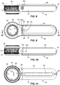
- Figs. 13 and 14 there are shown exploded views of the of the components of the device 60 demonstrating the assembly of the such components.
- the exploded view of Fig. 13 is a perspective view
- Fig. 14 is a direct side view of the same exploded view of Fig. 13 .
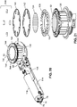
- lens retainer 120 lenses 62, lens tube retainer 122, center polarizer 124, base cover 108, torch button 86, dial PCB 128, dial PCB cover 130, polarization dial 74, spacer dial 72, main PCB 112, lens tube 132, PCB cover 114, LED base 134, LED PCB assembly 136, LED fin 138, battery 116, parallel polarizer 140, cross polarized polarizer 142, UV filters 144, LED base cap 146, spacer 148, spacer dial cap 150, face plate ring 152, face plate 96, handle cover 110 and rule 92.
- Fig. 15 demonstrates the position of the viewer 154 to view items located on the proximal side of the device, with the viewer 154 positioned on the distal side of the device, having an open view through the a lens assembly that includes lenses 62 arranged to provide a magnified view of the tissue to be examined.
- the lenses are preferably 10x magnification.
- the disclosed device lenses 62 is comprised of a compound lens with four spherical glass elements. While the device disclosed herein contemplates use of a compound lens with four spherical glass elements, other types of lenses, such as aspherical or those with polymer materials may be employed.
- the material for the lenses 62 may be molded PMMA with a hard coat surface. Other suitable material may also be used for the lenses 62.
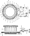
- the LED PCB assembly 136 prior to assembly.
- the PCB board comprises 24 LEDs, LEDS D1 through D24.
- the LEDS comprise different types of LEDs.
- LEDs D3, D6, D9 and D12 comprise UV LEDs having an output of about 365nm. As described herein with regard to other figures, LEDs D3, D6, D9 and D12 are not polarized, but emit light through an ZWB2 glass filter.
- LEDs D1, D13, D4, D16, D7, D19, D10 and D22 comprise white light LEDs.
- LEDs D1, D13, D4, D16, D7, D19, D10 and D22 as described herein with regard to other figures, emit light through a polarizer to emit cross-polarized light.
- LEDs D2, D5, D8, D11, D14, D17, D20 and D23 also comprise white light LEDs.
- LEDs D24, D21, D18 and D15 comprise orange light LEDs emitting light approximately in the range of 590nm.
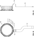
- the PCB board 136 as shown in Fig. 16 is prior to assembly, to form the PCB board 136 LED ring as shown in Figs. 17-19 .
- the LED portion 156 has the LEDs bonded on the PCB board each on fingers extending from the LED portion 156, wherein the LEDs are in electrical communication with the lead portion 158.
- the LED portion 156 is looped and connected at connection points 160 to form a ring.
- the fingers are angled outwardly from the ring at a 30-degree angle to expose the LEDs to direct light in the desired direction for positioning in the device 60.
- the lead portion 158 is formed to provide an electrical pathway within the device to avoid internal components by forming a pathway recess 162 as shown from the side in Fig. 19 . Referring to Fig.
- LEDs D23 parallel polarized white light
- D22 cross polarized white light
- D24 cross polarized orange light
- D11 parallel polarized white light
- D10 cross polarized white light
- D12 UV light with glass filter ZWB2
- Fig. 20 there is shown the LED ring 136 attached to the main PCB 114 with lead portion 158 electrically interfacing with the main PCB 114 so that the LEDs are in electrical communication with the items on the PCB board, including one or more microprocessors and battery 114 for power to the LEDs.
- Fig. 21 there is shown the fin 138 that engages the LED ring 136 and provides separation and fin walls 164 to create chambers for each LED to avoid light leakage between chambers.
- the fin 138 also provides a surface for filters 142, 140 and 142 to lay upon and to be fixed over each LED of the LED ring 136.
- the fins 164 may also be formed of a heat dissipating material and the fins 164 have surface areas to operate as a heat sink.
- a center polarizer 12 placed over the lenses 162 to polarize any light received from an object to be viewed.
- Filter layers are placed over the LEDs and include the following: a cross polarizer 142 having a circular structure and a number of openings and filter areas to cover some of the LEDs and the openings not covering other LEDs.
- the cross polarizer 142 has a polarization and is positioned in the device 60 to be orthogonal to the center polarizer 124.
- the lines in Figure 21 demonstrate the polarization orientation.
- Cross polarizer 142 covers and polarizes white LEDs D1, D4, D7, D10, D13, D16 and D19 and also covers and polarizes orange LEDs D12, D18, D21 and D24.
- the Cross polarizer 142 has openings and does not cover or polarize white LEDs D2, D5, D8, D11, D14, D17, D20 and D23 and also does not cover or polarized UV LEDs D3, D6, D9 and D12.
- a parallel polarizer 140 is polarized in the same orientation as the center polarizer 124.
- the parallel polarizer 140 has a circular structure and a number of openings and filter areas to cover some of the LEDs and not covering other LEDs.
- the parallel polarizer 140 covers and polarizes eight white LEDs D2, D5, D8, D11, D14, D17, D20 and D23.
- the parallel polarizer 140 does not cover or polarize eight white LEDs D1, D4, D7, D10, D13, D16 and D19 and also does not cover or polarize four orange LEDs D12, D18, D21 and D24.
- the parallel polarizer 140 also does not cover or polarized UV LEDs D3, D6, D9 and D12.
- the four UV LEDs are each covered by ZWB2 glass filters 144.
- the ZWB2 filter is a bandpass filter to filter the light emitted from the UV LEDs.
- the utilized bandpass filter for a particular LED attenuates all or a significant portion of frequencies outside of a desired frequency.
- Bandpass filters are placed over the light transmitting LED and may transmit a desired frequency range through the filter, while blocking all or most of certain frequency ranges of light from passing through the filter.
- a ZWB2 bandpass filter is used. Use of ZWB2 bandpass filters result in much better contrast in an image due to the elimination of all or a significant portion of visible light.
- an embodiment of the device discloses a ZWB2 filter
- other bandpass filters may be utilized that have a similar effect of a ZWB2 namely an optical filter that has higher transmittance in the UV spectrum than the visible spectrum.
- the embodiment of the device discloses the use of a ZWB2 bandpass filter offered by Optima, Inc. of Tokyo Japan.
- Optima offers optical filters under the designations ZBW1, ZBW3 and ZB1 having similar characteristics as a bandpass filter, blocking some wavelengths of light and the disclosure contemplates use of such filters.
- the filters 142 and 140 are overlaid onto the fin 138 so that they are stacked. Because the filters 142 and 140 have complementary openings and coverings, so that when placed in the proper position will not interfere or overlap with each other. In this regard, the filters 142 and 140 are reversable in stacking order, and as shown in Fig. 21 , the cross-polarizing filter 142 is placed directly over the fin 138 and the parallel polarizer 140 is overlaid on top of the cross polarizing filter 142. After filters 140 and 142 are positioned, there are openings for the LEDs D3, D6, D9 and D12, over which the ZWB2 filters 144 are placed.
- Figs 22, 23 and 24 there is shown components related to the operation of the electronics with the dial 74.
- a dial PCB 128 positioned on the lead portion 158.
- a reflective encoder 166 (shown in Fig. 22 ) is positioned and pointed to the dial 74 and particularly to the dial bottom 168 for optical rotation detection of the dial 74.
- the reflective encoder 166 is an Avago AEDR-8300 module manufactured by Avago Technologies of San Jose, CA, USA.
- the encoder 166 emits infrared signals and one or more optical readers on the encoder 166 detects reflection and can detect movement of the dial 74 by the lines or striations included on the dial bottom 168.
- LEDs D1, D4, D7, D10, D13, D16 and D19 are white light LEDs and due to the location of the cross polarizer 142 emit white cross-polarized light.
- LEDs D12, D18, D21 and D24 are orange LEDs with a wavelength of about 590nm, and due to the location of the cross-polarizer, such LEDs emit orange cross-polarized light.
- LEDs D2, D5, D8, D11, D14, D17, D20 and D23 are white light LEDs and due to the location of the parallel polarizer 140 emit parallel polarized white light.
- LEDs D3, D6, D9 and D12 are UV LEDs and with the placement of ZWB2 filters 144, such LEDs emit UV light modified by the bandpass filters. The positioning of different wavelength LEDs, filters and polarizers allows for the operation of the device 60 to emit variable polarization and operate in a plurality of modes.
- the USB port 76 and charging pins 78 may supply power to the device 60 through a power management circuit 170 which may be an integrated circuit chip.
- the circuit 170 may manage power input to supply power for charging the battery 116 and to provide signals to light the LED charge display 84.
- the circuit may manage power to a microprocessor 172.
- the microprocessor 172 received input from various sources, and depending on input, may drive various elements as a result.
- the battery 116 also supplies power to a 3.3v regulator that provides sufficient power to at least the encoder 166 and/or a Bluetooth module 176.
- the Bluetooth module 176 enables the device 60 to be wirelessly coupled to an external device (e.g.
- a mobile application may operate in place of the manual switches, allowing a user to implement the various modes by wirelessly communicating with the microprocessor 172 from an external device. As such, a user may selectively drive the LEDs of the device 60 in order to increase or decrease the effective penetration depth when viewing organic tissue by manipulating the cross polarized and parallel polarized light to simulate variable polarization as would be achieved by rotating one or more polarizers, wherein the device 60 polarizers remain stationary.
- the first flashlight mode involves the torch switch 90 which initiates and deactivates a flashlight type LED 88 that is not associated with any polarizers.
- the signal from the torch switch 90 is received by the microprocessor 172 and a signal is sent to the LED driver 178 to drive the torch LED 88 and may activate or deactivate user interface torch display 192 to let the user know the state of the torch mode.
- the polarization dial 74 When a user holds down the torch switch 90 while simultaneously turning the polarization dial 74, the brightness of the torch LED 88 may be adjusted, and the level of brightness saved in the system memory. Turning of the dial 74 effects the encoder 166 that provides a signal to the microprocessor indicating the position of the dial for determining brightness of the torch LED 88 and sending a signal to LED driver 178 to adjust the brightness.
- switch 104 initiates and deactivates the UV LEDs (comprising LEDs D3, D6, D9 and D12) and the UV light emitted is filtered through a bandpass filter 144.
- the signal from the UV switch 104 is received by the microprocessor 172 and a signal is sent to the LED driver 178 to drive the UV LEDs 180 and may activate or deactivate user interface mode display 194 to let the user know the state of the UV mode.
- the polarization dial 74 When a user holds down the UV switch 104 while simultaneously turning the polarization dial 74, the brightness of the UV LEDs may be adjusted, and the level of brightness saved in the system memory. Turning of the dial 74 effects the encoder 166 that provides a signal to the microprocessor indicating the position of the dial for determining brightness of the UV LEDs and sending a signal to the LED driver 178 to adjust brightness.
- pigment switch 106 initiates and deactivates both the orange pigment LEDs 182 (comprising LEDs D3, D6, D9 and D12) and white cross polarized LEDs 184 (comprising LEDs D1, D4, D7, D10, D13, D16 and D19), and the light emitted from the orange and white LEDs is cross polarized.
- the signal from the pigment switch 104 is received by the microprocessor 172 and a signal is sent to the LED drivers 190 and 178 to drive the white cross polarized LEDs 184 and pigment LEDs 182, respectively and may activate or deactivate user interface mode display 194 to let the user know the state of the pigment boost mode.
- the brightness of the orange LEDs may be adjusted, and the level of brightness saved in the system memory.
- Turning of the dial 74 effects the encoder 166 that provides a signal to the microprocessor indicating the position of the dial for determining brightness of the orange LEDs.
- the microprocessor 172 is capable of directing grouping of the parallel LEDs 186, pigment LEDs 182, UV LEDs 180 and/or torch LED 88 through an LED group select 188 circuit.
- variable polarization mode the user initiates power switch 102, and the device 60 defaults to cross polarization mode wherein white light LEDs 184 (comprising D1, D4, D7, D10, D13, D16 and D19) are activated and the light emitted from the white LEDs 184 is cross polarized.
- the signal from the power switch 102 is received by the microprocessor 172 and a signal is sent to the LED driver 190 to drive the white cross polarized LEDs 184 and may activate or deactivate user interface mode display 194 to let the user know the state of polarization by the LED bar 82.
- the encoder 166 senses movement of the dial, and sends sensor information to the microprocessor 172 so that the sensor can activate to determine the intensity for initiating both the white cross polarized light LEDs 184 (comprising D1, D4, D7, D10, D13, D16 and D19) through driver 190 and the white parallel polarized LEDs 186 through driver 178.
- the dial 74 is turned 10%, the cross polarized LED 184 intensity is at 90% and the parallel polarized LED 186 is at 10% simulating variable polarization.
- the intensity of the light for the cross polarized LEDs 184 is the inverse of that percentage.
- the LEDs 184 and 186 are at equal intensity, and thus simulate non-polarized light. In this way, by manipulating the inverse percentage of intensity between LEDs 184 and 186, the variable polarization mode simulates the mechanical movement of a polarizer.
- variable polarized mode a user may tap on the power switch 102 to toggle between cross-polarized mode (100% intensity of cross polarized LEDs 184) and non-polarized mode (50% intensity of cross polarized LEDs 184 and 50% intensity parallel LEDs 186).
- cross-polarized mode 100% intensity of cross polarized LEDs 184
- non-polarized mode 50% intensity of cross polarized LEDs 184 and 50% intensity parallel LEDs 186.
- a user can hold the power button 102 while simultaneously turning the dial 74 to adjust the brightness of the white LEDs 184 and white LEDs 186.
- first polarization direction and second polarization direction may refer to circular or elliptical directions (e.g. left-handedness, right-handedness) as well as linear directions.
Landscapes
- Health & Medical Sciences (AREA)
- Life Sciences & Earth Sciences (AREA)
- Physics & Mathematics (AREA)
- Engineering & Computer Science (AREA)
- Surgery (AREA)
- Biomedical Technology (AREA)
- Public Health (AREA)
- Veterinary Medicine (AREA)
- General Health & Medical Sciences (AREA)
- Pathology (AREA)
- Animal Behavior & Ethology (AREA)
- Molecular Biology (AREA)
- Medical Informatics (AREA)
- Heart & Thoracic Surgery (AREA)
- General Physics & Mathematics (AREA)
- Optics & Photonics (AREA)
- Biophysics (AREA)
- Nuclear Medicine, Radiotherapy & Molecular Imaging (AREA)
- Oral & Maxillofacial Surgery (AREA)
- General Engineering & Computer Science (AREA)
- Dermatology (AREA)
- Spectroscopy & Molecular Physics (AREA)
- Radiology & Medical Imaging (AREA)
- Dentistry (AREA)
- Radiation-Therapy Devices (AREA)
Abstract
Description
- This application relates to and claims the benefit of
U.S. Provisional Patent Application Serial No. 62/933,883, filed November 11, 2019 - Not Applicable
- The present disclosure relates generally to a hand-held illumination device used in medical examinations. More particularly, the present disclosure relates to an improved apparatus for enhanced viewing and illumination for medical examinations using cross-polarized and parallel-polarized light to aid in viewing internal structures as well as the skin surface.
- Medical examinations by physicians may employ the use of hand-held illuminators to assist the doctor in magnified and non-magnified viewing of the tissue of a patient. Hand-held illuminators without magnification include pen lights, which are widely used by general medical practitioners. Also, physicians and medical practitioners make use of hand-held illumination devices that have magnification including otoscopes, ophthalmoscopes and dermatoscopes. Typical otoscopes, ophthalmoscopes and dermatoscopes include a single lens for magnification and are designed for particular types of examination. However, a device that uses two magnification viewing lenses each having different powered magnification is described in United States Patent No.
10,441,379, issued on October 15, 2019 - Hand-held dermoscopy devices that use light with magnification can utilize polarizers or liquid-glass interfaces to reduce surface reflection and aid in viewing of deeper structures in the skin. For example, the DermLite® Platinum® product, manufactured by 3Gen, LLC, was developed to provide variable polarization. Variable polarization is achieved by a rotating dial. Rotation of the polarizer to a cross-polarization orientation cancels out the surface reflection for an in-depth look at the deeper pigmentation in lesion structure. Rotation to a parallel polarization orientation allows a clear view of the skin surface. The DermLite® Platinum® product requires manual manipulation of the dial which may cause the user to lose the viewing spot, or otherwise interfere with examination. Further, DermLite® Platinum® does not provide a user the ability to view the skin with an instantaneous switch over from cross-polarization to parallel polarization. United States Patent No.
5,742,392 issued on April 21, 1998 to Anderson entitled Polarized Material Inspection Apparatus the entire substance of which is incorporated herein by reference also discusses a rotatable polarizer to capture intermediate polarizations mechanically. - Additional dermoscopy apparatuses that employ light polarization to aid in viewing human skin surfaces and deeper tissue and structures of the skin are known and described in United States Patent Nos.
7,006,223, issued on February 28, 2006 to Mullani , and7,167,243, issued January 23, 2007 to Mullani both entitled Dermoscopy Epiluminescence Device Employing Cross and Parallel Polarization, the substance of each of which is wholly incorporated herein by reference. While the apparatuses described in these patents allow for an instantaneous switch over from cross-polarization to parallel polarization by digital control, they do not present any solutions for extending such digital control to allow for the intermediate polarizations that are possible with the manual dial of the DermLite® Platinum® product. A dermoscopy device identified as the Dermlite® DL3 device is manufactured and marketed by 3Gen, Inc. of San Juan Capistrano, CA which uses light and polarization. In the Dermlite® DL3 hand-held device, a series of light emitting diodes ("LEDs") are concentrically positioned around a magnifying lens to assist in lighting of a magnified image. The device includes LEDs that provide reduced glare and cross-polarized light to aid in canceling the reflected light from the skin, and other LEDs on the device provide non-polarized light for traditional immersion fluid dermoscopy or for simply employing non-polarized light. - It is also well known that different colored light penetrates to different depths in human skin tissue. Specific color wavelengths are absorbed differently by different components of the skin tissue. Such use of colored LEDs in a dermatoscope is described in United States Patent Nos.
7,027,153, issued on April 11, 2006 to Mullani , and7,167,244, issued on January 23, 2007 to Mullani , both entitled Dermoscopy Epiluminescence Device Employing Multiple Color Illumination Sources, the substance of each of which is wholly incorporated herein by reference. The previously identified references disclose the combined use of white LEDs, UV/blue LEDs (405nm), green/yellow LEDs (565nm) and orange/red (630nm). Alternatively, the 7,027,153 and 7,167,244 references suggest the use of LEDs with 480nm, 580nm and 660nm wavelengths. In addition, a dermoscopy device identified as the Dermlite ® II Multispectral dermoscopy device manufactured and marketed by 3Gen, Inc. of San Juan Capistrano, CA provides four sets of LED's comprising white, blue light (470nm) for surface pigmentation, yellow light (580nm) for superficial vascularity viewing, and red light (660nm) for viewing of pigmentation and vascularity with the deeper-penetrating red light frequency. - Dermotoscopes using coloured LEDs to augment the viewing of pigmentation of human tissue including skin are shown and described in United States Patent No.
9,458,990, issued October 4, 2016 to Mullani - Furthermore, hand-held medical illuminators have been used to introduce light into human tissue for observing sub-dermal structures using side-transillumination techniques whereby the light source is caused to be in direct contact with the skin to transfer light directly into the skin. One such technique is known and taught in United States Patent No.
5,146,923, issued on September 15, 1992 to Dhawan entitled Apparatus And Method For Skin Lesion Examination, the substance of which is wholly incorporated herein by reference. A combination of a surface illumination, epiluminescence and transillumination apparatus and method is demonstrated in the Nevoscope™ product manufactured by Translite LLC of Sugar Land, TX. Another known apparatus and method of viewing vein structures beneath the skin employs the use of transillumination as described in United States Patent No.7,874,698, issued on January 25, 2011 to Mullani entitled Translumination Having Orange Color Light, the substance of which is wholly incorporated herein by reference. United States Patent No.7,874,698 describes the use of orange light between 580 and 620 nm for transillumination imaging of deeper blood vessels in skin tissue. - When employing light polarization to aid in viewing deeper structures of the skin, it would be desirable to allow for a wide range of selection by the user while avoiding cumbersome and error-prone manual controls. In addition when employing light polarization, it would be desirable to achieve incremental changes in the polarization without the requirement of mechanically rotating a polarizers over a wide range of polarization selection.
- All publications herein are incorporated by reference to the same extent as if each individual publication or patent application were specifically and individually indicated to be incorporated by reference. Where a definition or use of a term in an incorporated reference is inconsistent or contrary to the definition of that term provided herein, the definition of that term provided herein applies and the definition of that term in the reference does not apply.
- The present disclosure contemplates various devices for overcoming the above drawbacks accompanying the known art. One aspect of the embodiments of the present disclosure is an illumination device for illuminating organic tissue such as a patient's skin. The illumination device may include a first set of one or more light emitting diodes (LEDs), a first polarizer arranged to polarize light emitted from the first set of one or more LEDs in a first polarization direction or first polarization state, a second set of one or more LEDs, a second polarizer arranged to polarize light emitted from the second set of one or more LEDs in a second polarization direction or second polarization state, a lens arranged to collect light from organic tissue illuminated by either one or both of the first and second sets of one or more LEDs, a viewing polarizer arranged to polarize the light collected from the organic tissue in the second polarization direction or second polarization state, a pulse generator operable to generate a pulsed voltage having an adjustable pulse width, and one or more drivers for driving one of the first and second sets of one or more LEDs according to the pulsed voltage and driving the other of the first and second sets of one or more LEDs according to an inverse of the pulsed voltage.
- A further embodiment of the disclosed device relates to is an illumination device for illuminating organic tissue such as a patient's skin. The illumination device may include a first set of one or more light emitting diodes (LEDs), a first polarizer arranged to polarize light emitted from the first set of one or more LEDs in a first polarization direction or first polarization state, a second set of one or more LEDs, a second polarizer arranged to polarize light emitted from the second set of one or more LEDs in a second polarization direction or second polarization state, a lens arranged to collect light from organic tissue illuminated by either one or both of the first and second sets of one or more LEDs, a viewing polarizer arranged to polarize the light collected from the organic tissue in the second polarization direction or second polarization state. A microprocessor for receiving a user input signal to drive one or more drivers for driving one of the first and second sets of one or more LEDs according to a predetermined ratio for setting the light intensity of the first and second sets of LEDs to achieve variable polarization without the need to mechanically rotate a polarizer. A dial is provided to adjust the light intensity, wherein the movement of the dial is detected by an optical encoder and the optical encoder transmits a signal related to the detected movement of the dial to a microprocessor to determine the light intensity for the first and second sets of one or more LEDs.
- Further benefits and advantages of the disclosed device will become apparent after careful reading of the detailed description with appropriate reference to the accompanying drawings.
- These and other features and advantages of the various embodiments disclosed herein will be better understood with respect to the following description and drawings, in which like numbers refer to like parts throughout, and in which:
-
Figure 1 is a top perspective view of the device according to a first embodiment of the present disclosure; -
Figure 2 is a bottom perspective view of the device according a first embodiment; -
Figure 3 is an exploded top view of the device according to the first embodiment; -
Figure 4 is an exploded bottom view of the device according to the first embodiment; -
Figure 5 is a schematic view of the device showing circuit components for operating the device according the first embodiment; -
Figure 6 is a top perspective view of the device according to the further embodiment; -
Figure 7 is bottom perspective view of the device according to the further embodiment with a disposable sanitary transparent cap shown exploded from the device; -
Figure 8 is a left side view of the device according to the further embodiment; -
Figure 9 is top view of the device according to the further embodiment; -
Figure 10 is a right side view of the device according to the further embodiment; -
Figure 11 is bottom view of the device according to the further embodiment; -
Figure 12 is a perspective view with the housing exploded from internal components of the device according to the further embodiment; -
Figure 13 is a perspective view with the interior and exterior components of the device exploded according to the further embodiment; -
Figure 14 is a side view with the interior and exterior components of the device exploded according to the further embodiment; -
Figure 15 is a cross sectional view of the device according to the further embodiment along the lines of 15-15 ofFig. 9 ; -
Figure 16 is a plan view of a LED printed circuit board assembly of the device according to the further embodiment prior to forming the assembly into the LED ring printed circuit board assembly; -
Figure 17 is a side perspective view of the LED ring printed circuit board assembly of the device according to the further embodiment; -
Figure 18 is a bottom view of the LED ring printed circuit board assembly of the device according to the further embodiment; -
Figure 19 is a side view of the LED ring printed circuit board assembly of the device according to the further embodiment; -
Figure 20 is a side perspective view of the LED ring printed circuit board assembly with a fin LED separator attached to the main printed circuit board and printed circuit board cover with the LED polarizers and filters placed over the LEDs according to the further embodiment; -
Figure 21 is a view of the assembled components ofFig. 20 with the LED polarizers and filters along with the center polarizer exploded therefrom according to the further embodiment; -
Figure 22 is a cut away bottom perspective view of the dial printed circuit board positioned relative to the rotating dial; -
Figure 23 is a cut away top perspective view of the dial printed circuit board positioned relative to the rotating dial; -
Figure 24 is a side view of dial printed circuit board positioned relative to the rotating dial; -
Figure 25 is a bottom view of the LED ring assembly junction with the main printed circuit board assembly; and -
Figure 26 is a schematic view of the device showing circuit components for operating the device according the second embodiment. - The present disclosure encompasses various devices for illuminating organic tissue such as a person's skin. The detailed description set forth below in connection with the appended drawings is intended as a description of several currently contemplated embodiments. It is not intended to represent the only form in which the disclosed subject matter may be developed or utilized. The description sets forth the functions and features in connection with the illustrated embodiments. It is to be understood, however, that the same or equivalent functions may be accomplished by different embodiments that are also intended to be encompassed within the scope of the present disclosure. It is further understood that the use of relational terms such as first and second and the like are used solely to distinguish one from another entity without necessarily requiring or implying any actual such relationship or order between such entities.
- The background, summary and the description herein includes information that may be useful in understanding the present disclosure. It is not an admission that any of the information provided herein is prior art or relevant to the presently claimed inventive subject matter, or that any publication specifically or implicitly referenced is prior art.
- In some embodiments, the numbers expressing dimensions, quantities, quantiles of ingredients, properties of materials, and so forth, used to describe and claim certain embodiments of the disclosure are to be understood as being modified in some instances by the term "about." Accordingly, in some embodiments, the numerical parameters set forth in the written description and attached claims are approximations that can vary depending upon the desired properties sought to be obtained by a particular embodiment. In some embodiments, the numerical parameters should be construed in light of the number of reported significant digits and by applying ordinary rounding techniques. Notwithstanding that the numerical ranges and parameters setting forth the broad scope of some embodiments of the disclosure are approximations, the numerical values set forth in the specific examples are reported as precisely as practicable. The numerical values presented in some embodiments of the disclose may contain certain errors necessarily resulting from the standard deviation found in their respective testing measurements.
- As used in the description herein and throughout the claims that follow, the meaning of "a," "an," and "the" includes plural reference unless the context clearly dictates otherwise. Also, as used in the description herein, the meaning of "in" includes "in" and "on" unless the context clearly dictates otherwise.
- As used herein, and unless the context dictates otherwise, the term "coupled to" is intended to include both direct coupling (in which two elements that are coupled to each other contact each other) and indirect coupling (in which at least one additional element is located between the two elements). Therefore, the terms "coupled to" and "coupled with" are used synonymously.
- Unless the context dictates the contrary, all ranges set forth herein should be interpreted as being inclusive of their endpoints, and open-ended ranges should be interpreted to include commercially practical values. Similarly, all lists of values should be considered as inclusive of intermediate values unless the context indicates the contrary.
- The recitation of ranges of values herein is merely intended to serve as a shorthand method of referring individually to each separate value falling within the range. Unless otherwise indicated herein, each individual value is incorporated into the specification as if it were individually recited herein. All methods described herein can be performed in any suitable order unless otherwise indicated herein or otherwise clearly contradicted by context. The use of any and all examples, or exemplary language (e.g. "such as") provided with respect to certain embodiments herein is intended merely to better illuminate the disclosure and does not pose a limitation on the scope of the claimed inventive subject matter. No language in the specification should be construed as indicating any non-claimed element essential to the practice of the inventive subject matter.
- Groupings of alternative elements or embodiments of the inventive subject matter disclosed herein are not to be construed as limitations. Each group member can be referred to and claimed individually or in any combination with other members of the group or other elements found herein. One or more members of a group can be included in, or deleted from, a group for reasons of convenience and/or patentability. When any such inclusion or deletion occurs, the specification is herein deemed to contain the group as modified thus fulfilling the written description of all Markush groups used in the appended claims.
- The following discussion provides many example embodiments of the inventive subject matter. Although each embodiment represents a single combination of inventive elements, the inventive subject matter is considered to include all possible combinations of the disclosed elements. Thus if one embodiment comprises elements A, B, and C, and a second embodiment comprises elements B and D, then the inventive subject matter is also considered to include other remaining combinations of A, B, C, or D, even if not explicitly disclosed. Various objects, features, aspects and advantages of the inventive subject matter will become more apparent from the following detailed description of preferred embodiments, along with the accompanying drawing figures in which like numerals represent like components.
- It should be apparent to those skilled in the art that many more modifications besides those already described are possible without departing from the inventive concepts herein. The inventive subject matter, therefore, is not to be restricted except in the scope of the appended claims. Moreover, in interpreting both the specification and the claims, all terms should be interpreted in the broadest possible manner consistent with the context. In particular, the terms "comprises" and "comprising" should be interpreted as referring to elements, components, or steps in a non-exclusive manner, indicating that the referenced elements, components, or steps may be present, or utilized, or combined with other elements, components, or steps that are not expressly referenced. Where the specification claims refers to at least one of something selected from the group consisting of A, B, C .... and N, the text should be interpreted as requiring only one element from the group, not A plus N, or B plus N, etc.
- It should be noted that any language herein directed to a computer or computing devices should be read to include any suitable combination of computing devices, including servers, interfaces, systems, databases, agents, peers, engines, controllers, modules, or other types of computing devices operating individually or collectively. One should appreciate the computing devices comprise at least one processor configured to execute a computer program product comprising software instructions stored on a tangible, non-transitory computer readable storage medium (e.g., hard drive, FPGA, PLA, solid state drive, RAM, flash, ROM, etc.). The software instructions configure or program the computing device to provide the roles, responsibilities, or other functionality as discussed with respect to the disclosed devices. Further, the disclosed technologies can be embodied as a computer program product that includes a non-transitory computer readable medium storing the software instructions that causes a processor to execute the disclosed steps associated with implementations of computer-based algorithms, processes, methods, or other instructions. In some embodiments, the various servers, systems, databases, or interfaces exchange data using standardized protocols or algorithms, possibly based on HTTP, HTTPS, TCP/IP, UPD/IP, AES, public-private key exchanges, web service APIs, known financial transaction protocols, or other electronic information exchanging methods. Data exchanges among devices can be conducted over a packet-switched network, the Internet, LAN, WAN, VPN, or other type of packet switched network; a circuit switched network; cell switched network; or other type of network.
- As used in the description herein and throughout the claims that follow, when a system, engine, server, device, module, or other computing element is described as configured to perform or execute functions on data in a memory, the meaning of "configured to" or "programmed to" is defined as one or more processors or cores of the computing element being programmed by a set of software instructions stored in the memory of the computing element to execute the set of functions on target data or data objects stored in the memory. It is understood that the use of "configured to" or "programmed to" (or similar language) should not be construed to invoke interpretation under 35 USC 112(f).
- Referring particularly to
Figures 1 and 2 , there are shown top and bottom perspective views, respectively, of adermoscopy epiluminescence device 12 according to an embodiment of the present disclosure. Thedevice 12 may be lightweight and compact and may be sized to easily fit within the shirt pocket of a user.Figure 1 shows the top perspective view of thedevice 12 showing the viewing port of anoptical lens 14 incorporated into ahousing 20. Abattery cover 22 may be removably secured to thehousing 20 to provide access to an interior compartment for insertion and removal of a battery. As shown inFigure 2 , a light portal may be incorporated into thehousing 20 to expose aviewing polarizer 24. A plurality of light emitting diodes (seeFigures 3 and4 ) may encircle the viewing polarizer within thehousing 20 and direct light though a multiplelayer filter ring 25 in order to selectively illuminate the surface of the organic tissue with cross-polarized and parallel-polarized light. By operation ofswitches device 12 can control the relative portion of cross-polarized light and parallel-polarized light by pulse width modulation, thus selectively increasing and decreasing the effective penetration depth of the view. For example, aswitch 16 for increasing the effective penetration depth and aswitch 18 for decreasing the effective penetration depth may be provided as momentary up and momentary down positions of a usually neutral rocker switch as shown. Alternatively, theswitches -
Figure 3 is an exploded top view of thedevice 12 andFigure 4 is an exploded bottom view of thedevice 12. Thehousing 20 may include a top component 20a and bottom component 20b. The top component 20a, bottom component 20b, andbattery cover 22 may be formed from molded lightweight durable plastic. The plastic may be a PVC derivative material and may be formed from acrylic or lexan. Additionally, the housing may be formed from metal such as aluminum. Components 20a, 20b and cover 22 may be interconnected to form theouter housing 20 as shown inFigures 1 and 2 . - The top housing component 20a may include an
aperture 26 for receiving the combination of theoptical lens 14 inserted within alens sleeve 28. Shown best inFigure 4 , the underside of the top housing component 20a is shown wherein theaperture 26 incorporates a downwardly protruding (upwardly inFigure 4 )collar 30 for receiving thelens 14 within thelens sleeve 28. Thelens sleeve 28 may incorporate anannular lip 29 which engages sloped sides of theaperture 26 to complete the exterior of the viewing port of thehousing 20. Thelens sleeve 28 may operate to securely hold thelens 14 in place within theaperture 26. Thelens 14 is preferably a 15mm diameter Hastings lens with a 10 X optical gain. Alternatively, the lens may be a single convex lens, a combination of two or more lenses, a double achromat lens, or a combination of double achromat lenses. In addition, the lens may incorporate aspherical lenses to accommodate better optics and lower distortion. Lenses coated with an antireflection coating may be used and a color filter may additionally be included to selectively filter light passing through the lens. - Although the drawings show a hand-held unit without imaging equipment attached, it is contemplated by the present disclosure that the same could be used with a camera, and that the size and shape of the lens could be modified to accommodate the same.
- The protruding
collar 30 may be part of the unitary structure of the upper housing component 20a. Thecollar 30, which may be cylindrical, may protrude through the interior components of thehousing 20, including a printed circuit board (PCB) 32 having anopening 33, to extend to the light portal of the bottom component 20b. Abattery 34 may nest within a battery chamber formed by the top component 20a and bottom component 20b. ThePCB 32 may include electrical contacts 36a and 36b for interfacing with battery contacts 38a and 38b. The upper housing 20a may include slots 40a and 40b to allow the PCB contacts 36a and 36b to protrude from thecircuit board 32 into the battery chamber and contact the battery leads 38a and 38b. Thebattery 34 may be an extended charge lithium battery. However, it is understood and contemplated by the present disclosure that the battery could be any suitable battery package such as a one-time lithium battery or rechargeable lithium battery. The disclosure additionally contemplates use of a DC power supply or an external power supply through a wire through contacts or a power port such as a USB or USB-C port. - The bottom component 20b may include a
viewing aperture 42 aligned with theaperture 26 of the top component 20a. At theviewing aperture 42, theviewing polarizer 24 inserted within asleeve 44 may cap off the opening of thecollar 30. Theviewing polarizer 24 may be composed of acrylic plastic with polarization material embedded within the polarizer. It is contemplated that theviewing polarizer 24 may alternatively be constructed of glass, with polarization material embedded or coated on the glass. In addition, theviewing polarizer 24 may be coated with a filter material that can selectively filter out some of the light frequencies emanating from the object. Alternatively, a secondary filter assembly made of plastic or glass with the capability of filtering the light may be placed in the path of theviewing lens 14 to filter out some of the light. - The bottom housing component 20b may include a
bottom collar 46 formed therein. Alip 48 incorporating a plurality of guide tabs may be formed between thecollar 46 and theviewing aperture 42. Thelip 48 and guide tabs may be adapted to engage a bottomannular polarizer 50 and a topannular polarizer 52. The top 52 and bottom 50 polarizers may have different polarization directions and may, for example, be 90 degrees out of phase. The bottom 50 polarizer may be in cross polarization with theviewing polarizer 24, and thetop polarizer 52 may be in parallel polarization with theviewing polarizer 24. The top 52 and bottom 50 polarizers may be composed of acrylic plastic and may include polarization at different angles. Thepolarizers annular polarizer viewing aperture 42 may be wide enough to permit a viewing corridor from thelens sleeve 28 through thehousing 20 to theviewing aperture 42 while allowing portions of the top 52 and bottom 50 polarizers to be exposed and to filter light emitting diodes inside thehousing 20. - In the example shown in the drawings, sixteen
light emitting diodes 58 ring thecircuit board 32, though it is contemplated that the number of diodes may be greater or less. Thediodes 58 are preferably white high light output Indium Gallium Nitride LEDs, but any suitable lighting diodes are appropriate. Everyother diode 58 may be on the same circuit, for example, the even diodes may be on a single circuit and the odd diodes may be on a separate single circuit. In the shown embodiment, theLEDs 58 are a standard white LED made with phosphorescence phosphors to create white light. It is additionally contemplated by the present disclosure that tri-colored LEDs, with individual red, green and blue LEDs that can combine to form white light, may be utilized. It is contemplated by the present disclosure that the LEDs may have focusing lenses to concentrate the light into a smaller and tighter beam. The LEDs may additionally be comprised of indium gallium arsenide material, or any other like semiconductor material. - As shown in
Figure 4 , thePCB 32 may additionally incorporate anintegrated circuit 74 for selectively driving theLEDs 58. Theintegrated circuit 74 may be electrically connected to theswitches battery 34 via thePCB 32. Theintegrated circuit 74 may additionally be communicatively coupled to an external device (e.g. a smartphone or other mobile device) via radio frequency transmission according to any of various wireless communication protocols such as Bluetooth. By manually operating theswitches integrated circuit 74 from an external device, a user may selectively drive theLEDs 58 as described in more detail below in order to increase or decrease the effective penetration depth when viewing organic tissue using thedevice 12. - The
first polarizer filter 50 may comprise a planar annular ring defining a generally circular center opening and an outer ring. The center opening of the annular ring of thefirst polarizer 50 may be positioned in alignment with the circularoptical lens 14 to provide an unobstructed view of the organic tissue through thelens 14 and thehousing 20. The outer ring of thefirst polarizer 50 may be arranged to polarize light emitted from a first set of one or more LEDs 58 (e.g. the even diodes) in a first polarization direction and to include a plurality of openings sized and positioned to correspond to thediodes 58 of a second set of one or more LEDs 58 (e.g. the odd diodes). Thus, the light emitted from the second set of one ormore LEDs 58 may pass through the openings unfiltered by thefirst polarizer 50. Thesecond polarizer filter 52 may likewise comprise a planar annular ring defining a generally circular center opening and an outer ring, with the center opening of said annular ring of thesecond polarizer 52 positioned in alignment with the circularoptical lens 14 to provide an unobstructed view of the organic tissue through thelens 14 andhousing 20. Thesecond polarizer 52 may be 90 degrees out of phase with thefirst polarizer 50 as noted above. The outer ring of thesecond polarizer 52 may be arranged to polarize light emitted from the second set of one or more LEDs 58 (e.g. the odd diodes) in a second polarization direction. Like thefirst polarizer 50, thesecond polarizer 52 may have a plurality of openings, but in the case of thesecond polarizer 52 the plurality of openings may be sized and positioned to correspond to thediodes 58 of the first set of one or more LEDs 58 (e.g. the even diodes). Thus, the light emitted from the first set of one ormore LEDs 58 may pass through the openings unfiltered by thesecond polarizer 52. -
Figure 5 is a schematic view of thedevice 12 showing circuit components for operating thedevice 12. By way of example, the components shown inFigure 5 are depicted as being components of the integrated circuit 74 (seeFigure 4 ), which may be a microcontroller for example. However, this is only one example, and it is contemplated that the functionality of the illustrated circuit components may be implemented on thePCB 32 in other ways as well, e.g. divided between multiple integrated circuits. As shown, thedevice 12 may include apulse generator 76, aninverter 78, afirst driver 80a, asecond driver 80b, and acontroller 82. - The
pulse generator 76 may be operable to generate a pulsed voltage having an adjustable pulse width p for driving one or both of the first and second sets ofLEDs 58 at a frequency f. In response to the pulsed voltage output by thepulse generator 76, thefirst driver 80a may drive the first set of one or more LEDs 58 (e.g. the even diodes). Thus, as shown on the right-hand side ofFigure 5 , the pulse of width p may represent a portion of a period 1/f during which the even diodes are turned on, such that reducing the pulse width p causes the even diodes to dim as perceived by the human eye or by a camera with a frame rate or shutter speed less than the frequency f. Meanwhile, in response to the inverted pulsed voltage as output by theinverter 78, thesecond driver 80b may drive the second set of one or more LEDs 58 (e.g. the odd diodes). Thus, as shown on the right-hand side ofFigure 5 , the inverse pulse width (1-p) may represent a portion of a period 1/f during which the odd diodes are turned on, such that reducing the pulse width p causes the odd diodes to brighten as the even diodes dim. By such an arrangement, the same total power may be used to drive theLEDs 58 irrespective of the pulse width p, with the even andodd diodes 58 being oppositely brightened and dimmed according to the setting of the pulse width p. - Operation of the
pulse generator 76 may be controlled by thecontroller 82 in response to user inputs made using theswitches 16, 18 (seeFigure 1 etc.). For example, as explained above, theswitch 16 may increase the effective penetration depth when viewing organic tissue using thedevice 12 and theswitch 18 may decrease the effective penetration depth. To this end, thecontroller 82 may increase the pulse width p in response to a user pressing theswitch 16 and may decrease the pulse width p in response to a user pressing theswitch 18. When the pulse width p is increased, the first set of one or more LEDs 58 (e.g. the even diodes), which are polarized in the first polarization direction by thefirst polarizer 50, are driven for a greater portion of each cycle 1/f. With theviewing polarizer 24 being cross polarized relative to the first polarization direction, the reflected light of thefirst LEDs 58 off the outermost layers of the organic tissue is blocked by theviewing polarizer 24. Meanwhile, the reflected light of thefirst LEDs 58 from deeper layers of the organic tissue will have a shifted polarization due to refraction and will thus be at least partially transmitted by theviewing polarizer 24. As a result, driving the first set of LEDs 58 (e.g. the even diodes) for a greater portion of each cycle may have the effect of increasing the effective penetration depth when viewing the organic tissue, thus deemphasizing surface features. - The opposite is true of the second set of LEDs 58 (e.g. the odd diodes), which are polarized in the second polarization direction by the
second polarizer 52. With theviewing polarizer 24 sharing the second polarization direction of the light of thesecond LEDs 58, the reflected light of thefirst LEDs 58 off the outermost layers of the organic tissue is polarized parallel to theviewing polarizer 24 and thus transmitted. Meanwhile, the reflected light of thefirst LEDs 58 from deeper layers of the organic tissue will have a shifted polarization due to refraction and will thus be at least partially blocked by theviewing polarizer 24. As a result, driving the second set of LEDs 58 (e.g. the odd diodes) for a greater portion of each cycle may have the effect of decreasing the effective penetration depth when viewing the organic tissue, thus emphasizing surface features. - In response to the user pressing the
switches controller 82 may increase or decrease the pulse width p by set increments, for example, p = 0%, p = 20%, p = 40%, p = 60%, p = 80%, and p = 100%, where percentages refer to one cycle 1/f. When theswitch 16 is pressed repeatedly until the pulse width p is set to 0%, the first set of LEDs 58 (even diodes) are off for the entire cycle while the second set of LEDs 58 (odd diodes) are on, resulting in parallel polarization of surface reflections and a minimum effective penetration depth. Conversely, when theswitch 18 is pressed repeatedly until the pulse width p is set to 100%, the first set of LEDs 58 (even diodes) are on for the entire cycle while the second set of LEDs 58 (odd diodes) are off, resulting in cross polarization of surface reflections and a maximum effective penetration depth. In between these two extremes, a portion of the light will be cross-polarized with the remainder parallel-polarized, resulting in an intermediate effective penetration depth according to the user's incremental selection. The relative portion of the light that is cross-polarized and parallel-polarized may be as shown in the following table.TABLE 1 Pulse Width "p" Cross-Polarized Portion Parallel-Polarized Portion 0% 0% 100% 20% 20% 80% 40% 40% 60% 60% 60% 40% 80% 80% 20% 100% 100% 0% - Larger increments (e.g. p = 0%, p = 25%, p = 50%, p = 75%, and p = 100%) and smaller increments (e.g. p = 0%, p = 10%, p = 20%, p = 30%, p = 40%, p = 50%, p = 60%, p = 70%, p = 80%, p = 90%, and p = 100%) are also contemplated, as well as a continuous or substantially continuous control, allowing the user to smoothly transition the view in the depth direction of the organic tissue.
- As shown in
Figure 5 , user inputs to thecontroller 82 may alternatively or additionally be made using an external device 84 (e.g. a smartphone or other mobile device) via wireless communication (e.g. Bluetooth). It is contemplated, for example, that theexternal device 84 may run a mobile application (e.g. a downloadable "app") that establishes a wireless connection with thecontroller 82 and generates a graphical user interface for adjusting settings of thepulse generator 76. Such a graphical user interface may include, for example, virtual sliders, buttons, etc. having the functions of theswitches Figure 1 for controlling the pulse width p. Additional functionality of the graphical user interface (or of additional switches on the device 12) may include, for example, adjusting the frequency f of the pulsed voltage (e.g. from 100 to 10,000,000 Hz), adjusting the forward current of the LED (e.g. by controlling thedrivers pulse generator 76 entirely and allow for static operation of the first and/or second sets of LEDs 58), and/or communicating with a camera of theexternal device 84 to capture an image of the organic tissue. In this regard, it is contemplated that thedevice 12 may be attachable to the external device 84 (e.g. by magnets and/or threaded connection) to align a camera of theexternal device 84 with theoptical lens 14 of thedevice 12. With the aid of a camera, it is contemplated that a three-dimensional map of the organic tissue may be constructed by combining images taken at a plurality of effective penetration depths. - In the illustrated example described above, it is assumed that every
other LED 58 is on the same circuit, with the even diodes on one circuit and the odd diodes on another circuit. That is, theLEDs 58 are grouped into two sets, each corresponding to itsown polarizer LEDs 58 are contemplated as well. For example, a third set ofLEDs 58 may be provided that emit light that is neither polarized by thebottom polarizer 50 nor by thetop polarizer 52 and instead remains non-polarized (e.g. by passing through corresponding holes in bothpolarizers 50, 52). Upon reflection at the organic tissue, such non-polarized light may be transmitted/blocked by theviewing polarizer 24 to a degree that does not depend on the reflection depth. A fourth set ofLEDs 58 may be provided that similarly emit non-polarized light but at an ultraviolet wavelength or another wavelength (e.g. blue). TheLEDs 58 may be arranged in a single ring such that one out of every fourLEDs 58 is on the same circuit. In the case of such three-circuit and four-circuit designs, it is contemplated that the first and second sets ofLEDs 58 may be driven in response to the output of thepulse generator 76 as shown inFigure 5 , with the third and fourth sets ofLEDs 58 being independently controlled by thecontroller 82 in response to user input (e.g. mode settings selected by anexternal device 84 or by additional switches on the device 12). - Along the same lines, sets of
LEDs 58 are shown as each having the same number of LEDs. However, the disclosure is not intended to be limited in this regard. For example, the first set ofLEDs 58 may have fewer LEDs than the second set ofLEDs 58, with the power level for the first set being greater to compensate for the reduced number of LEDs (e.g. by appropriate control of thedrivers LEDs 58, with the respective power levels being modified independently to account for differences in the number of LEDs of each circuit (as well as differences in the desired intensity of light). As noted above, independently modifying the power levels of the LEDs 58 (e.g. adjusting the forward current) may, in general, be used to control the intensity of light. Such analog control may be used instead of or in combination with the digital pulse width modulation described above in order to produce the desired combinations of cross-polarized and parallel-polarized light to change the effective penetration depth as described throughout this disclosure. - In the illustrated embodiments, the positions of various components of the device 12 (e.g. the
polarizers 50, 52) are described in relation to the positions ofLEDs 58. However, it is contemplated that the defined positions of theLEDs 58 more generally can be understood as the positions of functional light sources, which can be arbitrarily distant from the positions of actual LEDs, a light box, etc. through the use of fiber optics. For example, each of theLEDs 58 shown in the drawings may represent the output end of an optical fiber, with the input ends thereof receiving light from a shared illuminator. - It is known that combining orthogonally polarized light (parallel light combined with cross-polarized light) is effectively the same as unpolarized light. The polarization state of light can be mathematically described by the Stokes vector. The Stokes vector is determined by measuring the intensity of light through a parallel polarizer placed in front of a light sensor at several different orientations. Intensity measurements are also taken with a left hand and right hand circular polarizer in front of the light sensor. These intensity measurements are placed into a matrix where: I0 = the intensity of light filtered through a parallel polarizer at zero degrees; I90 is the intensity of light filtered through a parallel polarizer at 90 degrees; and I45 and I135 is the detected intensity of the light filtered through the polarizer at 45 and 135 degrees, respectively. Regarding the Stokes parameters: S0 is calculated from the sum of I0 and I90; S1 is the difference between I0 and I90; S2 is the difference between I45 and I135; and S3 is the difference between intensity filtered through circular polarizers I LHC and IRHc, The Stokes vector matrix is provided below.

- For unpolarized light, the light waves are randomly polarized and the intensity of the unpolarized light as measured through a polarizer are the same no matter the polarizer orientation. As such, for unpolarized light I0 = I90 = I45 = I135.
- Using the Stokes parameters, the results of the matrix describe the state of polarization for common polarization configurations:


- For Stokes parameters S1, I0 and I90 cancel each other out and resolve to zero (0). For S2, I45 and I135 cancel each other out and resolve to zero (0). For S3, since the devices described herein do not use circular polarization also therefore resolves to zero (0). As such the configuration results in the following Stokes vector:

- In the case of an equal combination of vertically polarized light and horizontally polarized light as described in the embodiments of the devices described herein, I0 = I90, so for Stoke parameter S1, I0 and I90 cancel out and resolve to zero (0). When the polarizer is diagonal I45 = I135 (although half of the intensity of I0 or I90), so for S2 I45 and I135 cancel out and resolve to zero (0). Again, there is no circular polarization so S3 is zero (0). The end result of the Stoke vector is the non-polarized light:

- The polarization as presented in the disclosed devices uses parallel polarization that provides a higher contrast image of the linear and cross polarized light, as opposed to elliptical polarization. With the disclosed device a healthcare practitioner can change the degrees of polarization to view the structural skin at differing depths to compare and contrast. Also, images that may be captured by a camera attached to the devices disclosed herein can store the images for later viewing and comparing and contrasting to aid in diagnosis and treatments.
- Referring particularly to
Figs. 6-7 there is shown anillumination device 60 representing a further embodiment of the device described herein.Fig. 6 shows the distal (away from the organic material to be viewed) upper perspective view of theillumination device 60, the top side of the device from which a user would view through themagnification lens 62.Figure 7 is a right-side lower perspective view of thedevice 60 showing the proximal (closest to the organic material to be viewed) of theillumination device 60. The proximal side is lower side of the device from which LEDs emit light to the object to be viewed.Fig. 7 also shows an auxiliary removably attachable disposableclear plastic cap 64 attachable to thedevice 60housing 66. Thedisposable cap 64 may be applied to the device over thefaceplate 96 and the surrounding surface of thehousing 66 for sanitary reasons to assist in preventing cross-contamination when using thedevice 60 on patients. Theplastic cap 64 is formed of a clear plastic material with flexion in the structure to allow it to be snap fit over thefaceplate 96 and surrounding area, to be securely attached when in use and easily removed by hand after thecap 64 is to be discarded. The plastic of thecap 64 may assist in keeping pathogens from attaching to thedevice 60 by covering a portion of the proximal surface ofdevice 60 and thecap 64 may be disposed of after a single use. Because the plastic of thecap 64 is transparent and has a low birefringence so that it does not disrupt the polarization state of the light passing through thecap 64 and does not significantly interfere with viewing the organic matter to be viewed through thedevice 60 optics including thelenses 62. - Referring to
Figs. 7-11 collectively, there are shown a number of external features of thedevice 60. Thehousing 66 includes ahead portion 68 incorporating the device optics and thehandle portion 70 incorporating electronic components of thedevice 60. In operation, a user grasps thehandle portion 70 to hold thehead 68 over an area of interest. Thehandle portion 70 has a number of LED indicators for showing the mode of operation or power, and positioned at the junction between thehead portion 68 and the handle portion 70 a number ergonomically placed buttons are provided to allow a user to initiate various lighting modes and power the device. - The
head portion 68 additionally incorporates two manual dials. Aspacer dial 72 is provided to allow a user to manually rotate to extend a threaded spacer that extends and retracts from the head 68 (not shown inFigs. 6-11 , being retracted in such drawings). Thespacer dial 72 is provided for adjusting position of a spacer by extending or retracting the same to adjust the focal distance to the object or tissue that is to be viewed (not shown). The spacer dial and spacer (not shown) operates similar to and consistent with the dial and spacer shown in United States Patent No.9,458,990, issued October 4, 2016 to Mullani head portion 68 additionally includes apolarization dial 74 that may be manually turned by a user in combination with other buttons to adjust or vary polarization in certain modes of operation, described in detail below. - A
power port 76 is provided at the end ofhandle portion 70, which is a USB-C port, however, it is contemplated by this disclosure that the power port may be any suitable electrical connector. Thepower port 76 is adapted to receive a male power port plug to supply power to the device and to charge an on-board battery (not shown inFigs. 6-11 ). In addition to thepower port 76, contact pins 78 are also provided to provide separate means of powering the device and charging the battery. A complementary charging base (not shown) may be provided with contacts to provide charge to thedevice 60. The contact pins 78 and charging device (not shown) operate similar to and consistent with the charging base shown in United States Patent No.9,458,990, issued October 4, 2016 lanyard openings 80 are provided for inserting a string, chord or other like device into the one of theopenings 80 and through and out of another of theopenings 80 to attach a chord, lanyard string or loop handle to the end of thehandle 70. - Referring to the various external indicators on the
device 60 inFigs. 7-11 , there is shown on the distal side of thedevice 60,polarization indicator bar 82. In operation when thedevice 60 is powered, theindicator 82 shows the degree of polarization. Thelight bar 82 with a first indicator LED light activated on the far left demonstrates cross polarization, and an "x" is imprinted on thehousing 66 next to the first LED on the far left. The indicator LED light activated on the right side of theLED bar 82 indicates parallel polarization, with two parallel lines imprinted on the device. An indicator LED light activated in the center ofLED bar 82 indicates 50% cross polarization and 50% parallel polarization resulting in non-polarized light. Thelight bar 82 can be activated along any point along thebar 82 to indicate the degree of polarization with cross polarization on the left side and parallel polarization on the right side as the extremes. Also located on the distal side of thehandle 70 are fourcharge indicator LEDs 84 for providing a user with charge status of the battery (not shown). When all fourindicators LEDs 84 are activated, this indicates a charge between 76 and 100 percent charge. Likewise, when three LEDs are activated, this indicates a charge between 51 and 75 percent. When two lightedLEDs 84 are indicated, the remaining charge is between 26 and 50 percent. Finally, when one of theLEDs 84 is activated, the remaining charge is between 1 and 25%. In addition, a pigmentboost LED indicator 98 is activated when thedevice 60 is operated in pigment boost mode, where orange LEDs are activated. Also, an ultraviolet (UV)LED indicator 100 is activated when thedevice 60 is operated in UV mode. - Located on the distal side of the
handle 70 is atorch button 86 is provided that activates and deactivates a flashlight, or torch light 86 on the proximal side of thehandle 70. Thetorch light 88 provides convenient tool for use by the medical practitioner to operate much like a flashlight and is not associated with the optics or polarization filters of thedevice 60. Twoindicator LEDs 90 are located in the center of thetorch button 86 to identify status of thetorch light 88. Tapping thetorch button 86 activates thetorch light 88, and in the instance where the LEDs in thedevice 60 head are turned on, those LED lights will turn off for operating in torch mode. In operation, the user may tap and hold thetorch button 86 while simultaneously turning thepolarization dial 74 to adjust thetorch LED 88 brightness. The microprocessor (not shown inFigs. 6-11 ) may store in an on board non-transitory memory device (not shown inFigs. 6-11 ) the level of brightness, and upon the next initiation of thetorch 86, the torch will light at the same brightness. - A
power button 102 is provided on left side of thehousing 66 of thedevice 60 to turn on thedevice 60 power. Upon tappingpower button 102 the device defaults to cross polarizer mode, and as such thelight bar 82 show the status of cross polarizing mode. Thepower button 102 can then be tapped to toggle between cross polarized mode and non-polarized mode (theindicator bar 82 showing a center LED activated). In addition, thepower button 102 may alternately be toggled between cross-polarized and any other polarization state (i.e. parallel polarized or any polarization in between cross-polarized and parallel polarized). The alternate toggle state may be set by turning the polarization dial until the desired alternative polarization state is reached and then simultaneously holding down theUV button 104 and the andpigment boost button 106 for two (2) seconds to save this polarization state as the new default alternate toggle setting. Another way to incrementally toggle between cross polarized mode, non-polarized mode and parallel polarized mode, and all points in between, when thepower button 102 has been activated, a user may turn thepolarizer dial 74. In operation, thepower button 102 is tapped, defaulting to cross polarized mode. If the user turns the polarizer dial clockwise, there will be no effect. However, if the user turns the polarizer dial counterclockwise the polarization will gradually change to reach non-polarized mode and parallel polarization at the far extreme. At any point after turning thedial 74 counterclockwise, the user can move thedial 74 clockwise to move back to a previous polarization, including back to the far extreme of cross polarization. Holding thepower button 102 for one second turns the power to the device off. Also, tapping thepower button 102 and holding thebutton 102 while turning thedial 74 adjusts the brightness of the white LEDs (not shown inFigs. 6-11 ) in thehead 68 of thedevice 60. The microprocessor may store in an on board non-transitory memory the level of brightness of white LEDs, and upon the next initiation of thebutton 102, the white LEDs will light at the same brightness. - A
UV mode button 104 is provided on the right side of thehousing 66 of thedevice 60 to enable UV LEDs (not shown inFigs 6-11 ) in thehead 68 to activate. The UV LEDs operate to the exclusion of any other LEDs in thehead 68. For example, if thepower button 102 is activated, operating in cross-polarized mode for example, the tapping ofUV mode button 104 will deactivate all other LEDs and turn on only the UV LEDs. Also, tapping the power buttonUV mode button 104 and holding thebutton 104 while turning thedial 74 adjusts the brightness of the UV LEDs. The microprocessor may store in an on board non-transitory memory the level of brightness of UV LEDs, and upon the next initiation of thebutton 104, the UV LEDs will light at the same brightness. - A
pigment boost button 106 is provided on the right side of thehousing 66 of thedevice 60 to enable orange and while LEDs (not shown inFigs 6-11 ) in thehead 68 to activate. The orange and while LEDs operate to the exclusion of any other LEDs in thehead 68. For example, if thepower button 102 is activated, operating in cross-polarized mode, the tapping of pigmentboost mode button 106 will deactivate all other LEDs and turn on only the orange and white LEDs to operate in pigment boost mode that enhances viewing of pigmented tissue and lesions. A thorough discussion of the use of orange LEDs in dermatoscopes may be found in United States Patent No.9,458,990, issued October 4, 2016 to Mullani boost mode button 106 and holding thebutton 106 while turning thedial 74 adjusts the brightness of the orange and white LEDs. The microprocessor may store in an on board non-transitory memory the level of brightness of orange and white LEDs when operating in pigment boost mode, and upon the next initiation of thebutton 106, the orange and white LEDs will light at the same brightness. - On the proximal side of the
device 60, an elongate ferriticstainless steel ruler 92 is attached to thehandle 70. A recess with embedded magnets to attract and attach theruler 92 is provided. In addition, a space is provided on thehandle 70 below theruler 92 to allow a user to push down on the ruler to create a slight deformation so that the ends of therule 92 may bend upward to allow a user to easily access and remove theruler 92. The ruler may be used by the medical practitioner for any purpose, including the potential measuring of skin lesions. In addition, ameasurement indicia 94 is screened or etched on to the glass of thefaceplate 96 to provide the user a measurement aid when viewing features through the optics of the device. - Referring particularly to
Fig. 12 there is shown an exploded view of thehousing 66 from the internal components of thedevice 60. Thehousing 66 comprises abase cover 108 and handlecover 110. Also shown is theruler 92 separated from thehandle cover 110. The internal components include themain PCB 112 and mailPCB cover 114. Abattery 116 nests within thePCB cover 114 and adjacent thePCB board 112 and thebattery 116 is electrically interconnected to thepower port 76 andcontacts 78 for charging. Thebattery 116 also provides power to the electrical components of thedevice 60. Thebattery 116 is a lithium polymer rechargeable battery, however it is understood that any suitable battery type power source may be used in relation to thedevice 60. Anaperture 118 is formed into thebase cover 108 to provide exposure to the torch button. Light pipes (not shown) or other light transmitting mechanism may be formed on the interior of thebase cover 108 to transmit light from LEDs located on themain PCB board 112 to provide visible light to the indicators such aspolarizer indicator bar 82,battery status indicators 84,torch indicators 90, pigment boost mode indicator 98and UVlight indicators 100. Thedial 74 is free to rotate below thebase cover 108. - Referring particularly to
Figs. 13 and14 there are shown exploded views of the of the components of thedevice 60 demonstrating the assembly of the such components. The exploded view ofFig. 13 is a perspective view, andFig. 14 is a direct side view of the same exploded view ofFig. 13 . Moving from the proximal end to the distal end, the components are identified as follows:lens retainer 120,lenses 62,lens tube retainer 122,center polarizer 124,base cover 108,torch button 86, dialPCB 128, dialPCB cover 130,polarization dial 74,spacer dial 72,main PCB 112,lens tube 132,PCB cover 114,LED base 134,LED PCB assembly 136,LED fin 138,battery 116,parallel polarizer 140, crosspolarized polarizer 142, UV filters 144,LED base cap 146,spacer 148,spacer dial cap 150,face plate ring 152,face plate 96, handlecover 110 andrule 92. It is noted that the position of theparallel polarizer 140 andcross polarizer 142 are interchangeable since they are stacked upon one another, and the polarizers do not interfere with each other due to coordinated spacings of openings, described in more detail with regard toFig. 21 . - Referring particularly to
Fig. 15 there is shown a cross sectional view along lines 15-15 shown inFig. 9 .Fig. 15 demonstrates the position of theviewer 154 to view items located on the proximal side of the device, with theviewer 154 positioned on the distal side of the device, having an open view through the a lens assembly that includeslenses 62 arranged to provide a magnified view of the tissue to be examined. The lenses are preferably 10x magnification. The discloseddevice lenses 62 is comprised of a compound lens with four spherical glass elements. While the device disclosed herein contemplates use of a compound lens with four spherical glass elements, other types of lenses, such as aspherical or those with polymer materials may be employed. The material for thelenses 62 may be molded PMMA with a hard coat surface. Other suitable material may also be used for thelenses 62. - Referring to
Fig. 16 there is shown theLED PCB assembly 136 prior to assembly. The PCB board comprises 24 LEDs, LEDS D1 through D24. The LEDS comprise different types of LEDs. LEDs D3, D6, D9 and D12 comprise UV LEDs having an output of about 365nm. As described herein with regard to other figures, LEDs D3, D6, D9 and D12 are not polarized, but emit light through an ZWB2 glass filter. LEDs D1, D13, D4, D16, D7, D19, D10 and D22 comprise white light LEDs. LEDs D1, D13, D4, D16, D7, D19, D10 and D22 as described herein with regard to other figures, emit light through a polarizer to emit cross-polarized light. LEDs D2, D5, D8, D11, D14, D17, D20 and D23 also comprise white light LEDs. LEDs D2, D5, D8, D11, D14, D17, D20 and D23 as described herein with regard to other figures, emit light through a polarizer to emit parallel-polarized light. LEDs D24, D21, D18 and D15 comprise orange light LEDs emitting light approximately in the range of 590nm. LEDs D24, D21, D18 and D15 as described herein with regard to other figures, emit light through a polarizer to emit cross-polarized light. - The
PCB board 136 as shown inFig. 16 is prior to assembly, to form thePCB board 136 LED ring as shown inFigs. 17-19 . TheLED portion 156 has the LEDs bonded on the PCB board each on fingers extending from theLED portion 156, wherein the LEDs are in electrical communication with thelead portion 158. TheLED portion 156 is looped and connected at connection points 160 to form a ring. The fingers are angled outwardly from the ring at a 30-degree angle to expose the LEDs to direct light in the desired direction for positioning in thedevice 60. Thelead portion 158 is formed to provide an electrical pathway within the device to avoid internal components by forming apathway recess 162 as shown from the side inFig. 19 . Referring toFig. 18 once the LED filters are put in place, the references to the LEDs are as follows: LEDs D23 (parallel polarized white light), D22 (cross polarized white light), D24 (cross polarized orange light), D11 (parallel polarized white light), D10 (cross polarized white light) and D12 (UV light with glass filter ZWB2). This pattern is repeated four times along the length of theLED circle 136. - Referring particularly to
Fig. 20 there is shown theLED ring 136 attached to themain PCB 114 withlead portion 158 electrically interfacing with themain PCB 114 so that the LEDs are in electrical communication with the items on the PCB board, including one or more microprocessors andbattery 114 for power to the LEDs. Referring toFig. 21 there is shown thefin 138 that engages theLED ring 136 and provides separation andfin walls 164 to create chambers for each LED to avoid light leakage between chambers. Thefin 138 also provides a surface forfilters LED ring 136. Thefins 164 may also be formed of a heat dissipating material and thefins 164 have surface areas to operate as a heat sink. Acenter polarizer 12 placed over thelenses 162 to polarize any light received from an object to be viewed. - Filter layers are placed over the LEDs and include the following: a
cross polarizer 142 having a circular structure and a number of openings and filter areas to cover some of the LEDs and the openings not covering other LEDs. Thecross polarizer 142 has a polarization and is positioned in thedevice 60 to be orthogonal to thecenter polarizer 124. The lines inFigure 21 demonstrate the polarization orientation.Cross polarizer 142 covers and polarizes white LEDs D1, D4, D7, D10, D13, D16 and D19 and also covers and polarizes orange LEDs D12, D18, D21 and D24. TheCross polarizer 142 has openings and does not cover or polarize white LEDs D2, D5, D8, D11, D14, D17, D20 and D23 and also does not cover or polarized UV LEDs D3, D6, D9 and D12. - A
parallel polarizer 140 is polarized in the same orientation as thecenter polarizer 124. Theparallel polarizer 140 has a circular structure and a number of openings and filter areas to cover some of the LEDs and not covering other LEDs. Theparallel polarizer 140 covers and polarizes eight white LEDs D2, D5, D8, D11, D14, D17, D20 and D23. Theparallel polarizer 140 does not cover or polarize eight white LEDs D1, D4, D7, D10, D13, D16 and D19 and also does not cover or polarize four orange LEDs D12, D18, D21 and D24. Theparallel polarizer 140 also does not cover or polarized UV LEDs D3, D6, D9 and D12. - The four UV LEDs are each covered by ZWB2 glass filters 144. The ZWB2 filter is a bandpass filter to filter the light emitted from the UV LEDs. The utilized bandpass filter for a particular LED attenuates all or a significant portion of frequencies outside of a desired frequency. Bandpass filters are placed over the light transmitting LED and may transmit a desired frequency range through the filter, while blocking all or most of certain frequency ranges of light from passing through the filter. In the further embodiment of the device, a ZWB2 bandpass filter is used. Use of ZWB2 bandpass filters result in much better contrast in an image due to the elimination of all or a significant portion of visible light. Although an embodiment of the device discloses a ZWB2 filter, it is contemplated by the present disclosure that other bandpass filters may be utilized that have a similar effect of a ZWB2 namely an optical filter that has higher transmittance in the UV spectrum than the visible spectrum. The embodiment of the device discloses the use of a ZWB2 bandpass filter offered by Optima, Inc. of Tokyo Japan. Optima offers optical filters under the designations ZBW1, ZBW3 and ZB1 having similar characteristics as a bandpass filter, blocking some wavelengths of light and the disclosure contemplates use of such filters. In addition, other manufactures offer filters having near characteristics of the ZWB2 filter, namely Hoya Corporation of Tokyo, Japan offers U-360 and UL365 Glass filters and Schott North America, Inc of Duryea, PA offer a product under the designation of UG11. Hoya also offers U-340 and U-330 glass filters that may be used and other Schott products under the designations UG1 and UG5 are contemplated by the disclosure.
- The
filters fin 138 so that they are stacked. Because thefilters filters Fig. 21 , thecross-polarizing filter 142 is placed directly over thefin 138 and theparallel polarizer 140 is overlaid on top of the crosspolarizing filter 142. Afterfilters - Referring to
Figs 22, 23 and24 there is shown components related to the operation of the electronics with thedial 74. Adial PCB 128 positioned on thelead portion 158. On the side ofdial PCB 128 closest to the dial 74 a reflective encoder 166 (shown inFig. 22 ) is positioned and pointed to thedial 74 and particularly to thedial bottom 168 for optical rotation detection of thedial 74. Thereflective encoder 166 is an Avago AEDR-8300 module manufactured by Avago Technologies of San Jose, CA, USA. Theencoder 166 emits infrared signals and one or more optical readers on theencoder 166 detects reflection and can detect movement of thedial 74 by the lines or striations included on thedial bottom 168. Ondial 74 there are 212 lines per inch enabling detection of slight movement. Detecting rotation, the encoder sends signals to a microprocessor (not shown) regarding the position of the dial. - Referring to
Figure 25 there is shown the top view of theLED assembly 136, withfilters cross polarizer 142 emit white cross-polarized light. LEDs D12, D18, D21 and D24 are orange LEDs with a wavelength of about 590nm, and due to the location of the cross-polarizer, such LEDs emit orange cross-polarized light. LEDs D2, D5, D8, D11, D14, D17, D20 and D23 are white light LEDs and due to the location of theparallel polarizer 140 emit parallel polarized white light. LEDs D3, D6, D9 and D12 are UV LEDs and with the placement of ZWB2 filters 144, such LEDs emit UV light modified by the bandpass filters. The positioning of different wavelength LEDs, filters and polarizers allows for the operation of thedevice 60 to emit variable polarization and operate in a plurality of modes. - Referring to
Fig. 26 is a schematic of the electronic components of thedevice 60. TheUSB port 76 and chargingpins 78 may supply power to thedevice 60 through apower management circuit 170 which may be an integrated circuit chip. Thecircuit 170 may manage power input to supply power for charging thebattery 116 and to provide signals to light theLED charge display 84. Also, the circuit may manage power to amicroprocessor 172. Themicroprocessor 172 received input from various sources, and depending on input, may drive various elements as a result. Thebattery 116 also supplies power to a 3.3v regulator that provides sufficient power to at least theencoder 166 and/or aBluetooth module 176. TheBluetooth module 176 enables thedevice 60 to be wirelessly coupled to an external device (e.g. a smartphone or other mobile device) via radio frequency transmission according to any of various wireless communication protocol, including Bluetooth. A mobile application may operate in place of the manual switches, allowing a user to implement the various modes by wirelessly communicating with themicroprocessor 172 from an external device. As such, a user may selectively drive the LEDs of thedevice 60 in order to increase or decrease the effective penetration depth when viewing organic tissue by manipulating the cross polarized and parallel polarized light to simulate variable polarization as would be achieved by rotating one or more polarizers, wherein thedevice 60 polarizers remain stationary. - In
device 60 there are three modes of operation that are independent of variable polarization. The first flashlight mode involves thetorch switch 90 which initiates and deactivates aflashlight type LED 88 that is not associated with any polarizers. The signal from thetorch switch 90 is received by themicroprocessor 172 and a signal is sent to theLED driver 178 to drive thetorch LED 88 and may activate or deactivate userinterface torch display 192 to let the user know the state of the torch mode. When a user holds down thetorch switch 90 while simultaneously turning thepolarization dial 74, the brightness of thetorch LED 88 may be adjusted, and the level of brightness saved in the system memory. Turning of thedial 74 effects theencoder 166 that provides a signal to the microprocessor indicating the position of the dial for determining brightness of thetorch LED 88 and sending a signal toLED driver 178 to adjust the brightness. - In a further UV mode,
switch 104 initiates and deactivates the UV LEDs (comprising LEDs D3, D6, D9 and D12) and the UV light emitted is filtered through abandpass filter 144. The signal from theUV switch 104 is received by themicroprocessor 172 and a signal is sent to theLED driver 178 to drive theUV LEDs 180 and may activate or deactivate userinterface mode display 194 to let the user know the state of the UV mode. When a user holds down theUV switch 104 while simultaneously turning thepolarization dial 74, the brightness of the UV LEDs may be adjusted, and the level of brightness saved in the system memory. Turning of thedial 74 effects theencoder 166 that provides a signal to the microprocessor indicating the position of the dial for determining brightness of the UV LEDs and sending a signal to theLED driver 178 to adjust brightness. - In a further pigment boost mode,
pigment switch 106 initiates and deactivates both the orange pigment LEDs 182 (comprising LEDs D3, D6, D9 and D12) and white cross polarized LEDs 184 (comprising LEDs D1, D4, D7, D10, D13, D16 and D19), and the light emitted from the orange and white LEDs is cross polarized. The signal from thepigment switch 104 is received by themicroprocessor 172 and a signal is sent to theLED drivers polarized LEDs 184 andpigment LEDs 182, respectively and may activate or deactivate userinterface mode display 194 to let the user know the state of the pigment boost mode. When a user holds down thepigment switch 106 while simultaneously turning thepolarization dial 74, the brightness of the orange LEDs may be adjusted, and the level of brightness saved in the system memory. Turning of thedial 74 effects theencoder 166 that provides a signal to the microprocessor indicating the position of the dial for determining brightness of the orange LEDs. Themicroprocessor 172 is capable of directing grouping of theparallel LEDs 186,pigment LEDs 182,UV LEDs 180 and/ortorch LED 88 through an LED group select 188 circuit. - In variable polarization mode, the user initiates
power switch 102, and thedevice 60 defaults to cross polarization mode wherein white light LEDs 184 (comprising D1, D4, D7, D10, D13, D16 and D19) are activated and the light emitted from thewhite LEDs 184 is cross polarized. The signal from thepower switch 102 is received by themicroprocessor 172 and a signal is sent to theLED driver 190 to drive the white crosspolarized LEDs 184 and may activate or deactivate userinterface mode display 194 to let the user know the state of polarization by theLED bar 82. By turning thedial 74 counterclockwise, theencoder 166 senses movement of the dial, and sends sensor information to themicroprocessor 172 so that the sensor can activate to determine the intensity for initiating both the white cross polarized light LEDs 184 (comprising D1, D4, D7, D10, D13, D16 and D19) throughdriver 190 and the white parallelpolarized LEDs 186 throughdriver 178. For example, if thedial 74 is turned 10%, the cross polarizedLED 184 intensity is at 90% and the parallelpolarized LED 186 is at 10% simulating variable polarization. In this regard, whatever percentage movement of thedial 74 in the clockwise direction, the intensity of the light for the cross polarizedLEDs 184 is the inverse of that percentage. At the midpoint for turning thedial 74, theLEDs LEDs - In a variation of the variable polarized mode, a user may tap on the
power switch 102 to toggle between cross-polarized mode (100% intensity of cross polarized LEDs 184) and non-polarized mode (50% intensity of cross polarizedLEDs power button 102, a user can hold thepower button 102 while simultaneously turning thedial 74 to adjust the brightness of thewhite LEDs 184 andwhite LEDs 186. - Throughout the disclosure, the term "parallel polarized" is interchangeable with "linear polarized" and also is intended to encompass co-polarized light in the case of circular or elliptical polarization. By the same token, the "first polarization direction" and "second polarization direction" may refer to circular or elliptical directions (e.g. left-handedness, right-handedness) as well as linear directions.
- The above description is given by way of example, and not limitation. Given the above disclosure, one skilled in the art could devise variations that are within the scope and spirit of the disclosure herein. Further, the various features of the embodiments disclosed herein can be used alone, or in varying combinations with each other and are not intended to be limited to the specific combination described herein. Thus, the scope of the claims is not to be limited by the illustrated embodiments.
Claims (20)
- An illumination device for illuminating organic tissue, the illumination device comprising:a first set of one or more light emitting diodes (LEDs);a first polarizer arranged to polarize light emitted from the first set of one or more LEDs in a first polarization state;a second set of one or more LEDs;a second polarizer arranged to polarize light emitted from the second set of one or more LEDs in a second polarization state;a lens arranged to collect light from organic tissue illuminated by either one or both of the first and second sets of one or more LEDs;a viewing polarizer arranged to polarize the light collected from the organic tissue in the second polarization state;one or more drivers for driving one of the first and second sets of one or more LEDs according to a first signal and driving the other of the first and second sets of LEDs according to a second signal; anda microprocessor operable to generate the first signal as a function of a user input value and to generate the second signal as a function of the same user input value.
- The illumination device of claim 1 wherein, for a given change in the user input value, the first and second signals vary oppositely to each other.
- The illumination device of claim 2 wherein the first and second signals are pulse width modulation (PWM) signals.
- The illumination device of claim 3 wherein the microprocessor is operable to generate the first and second signals such that the first signal has a maximum duty cycle and the second signal has a minimum duty cycle for the same user input value.
- The illumination device of claim 2 wherein the first and second signals are continuous current signals.
- The illumination device of claim 5 wherein the microprocessor is operable to generate the first and second signals such that the first signal has a maximum current value and the second signal has a minimum current value for the same user input value.
- The illumination device of claim 1 wherein the first and second signals are pulse width modulation (PWM) signals.
- The illumination device of claim 7 wherein the microprocessor is operable to generate the first and second signals such that the first signal has a maximum duty cycle and the second signal has a minimum duty cycle for the same user input value.
- The illumination device of claim 1 wherein the first and second signals are continuous current signals.
- The illumination device of claim 9 wherein the microprocessor is operable to generate the first and second signals such that the first signal has a maximum current value and the second signal has a minimum current value for the same user input value.
- The illumination device of claim 1 further comprising a dial, the user input value being derived from a change in position of the dial.
- The illumination device of claim 11 further comprising an optical encoder configured to detect the change in the position of the dial.
- An illumination device for illuminating organic tissue, the illumination device comprising:a first set of one or more light emitting diodes (LEDs);a first polarizer arranged to polarize light emitted from the first set of one or more LEDs in a first polarization direction;a second set of one or more LEDs;a second polarizer arranged to polarize light emitted from the second set of one or more LEDs in a second polarization direction;a lens arranged to collect light from organic tissue illuminated by either one or both of the first and second sets of one or more LEDs;a viewing polarizer arranged to polarize the light collected from the organic tissue in the second polarization direction;a pulse generator operable to generate a pulsed voltage having an adjustable pulse width; andone or more drivers for driving one of the first and second sets of one or more LEDs according to the pulsed voltage and driving the other of the first and second sets of one or more LEDs according to an inverse of the pulsed voltage.
- The illumination device of claim 13 further comprising a dial whose position determines a user input value for adjusting the adjustable pulse width.
- The illumination device of claim 14 further comprising an optical encoder configured to generate the user input value from the position of the dial.
- An illumination device for illuminating organic tissue, the illumination device comprising:a first set of one or more light emitting diodes (LEDs);a first polarizer arranged to polarize light emitted from the first set of one or more LEDs in a first polarization state;a second set of one or more LEDs;a second polarizer arranged to polarize light emitted from the second set of one or more LEDs in a second polarization state;a lens arranged to collect light from organic tissue illuminated by either one or both of the first and second sets of one or more LEDs;a viewing polarizer arranged to polarize the light collected from the organic tissue in the second polarization state;one or more drivers for driving the first and second sets of one or more LEDs; andmeans for controlling the one or more drivers to drive one of the first and second sets of one or more LEDs according to a user input value and to drive the other of the first and second sets of one or more LEDs according to the same user input value.
- The illumination device of claim 16 wherein, for a given change in the user input value, the means for controlling the one or more drivers controls the one or more drivers to increase an intensity of one of the first and second sets of one or more LEDs and to decrease an intensity of the other of the first and second sets of one or more LEDs.
- The illumination device of claim 16 wherein the means for controlling the one or more drivers controls the one or more drivers to drive one of the first and second sets of one or more LEDs at a maximum intensity and to drive the other of the first and second sets of one or more LEDs at a minimum intensity for the same user input value.
- The illumination device of claim 16 further comprising a dial, the user input value being derived from a change in the position of the dial.
- The illumination device of claim 19 further comprising an optical encoder configured to detect the change in position of the dial.
Applications Claiming Priority (2)
| Application Number | Priority Date | Filing Date | Title |
|---|---|---|---|
| US201962933883P | 2019-11-11 | 2019-11-11 | |
| US17/093,467 US11395714B2 (en) | 2019-11-11 | 2020-11-09 | Medical illuminator with variable polarization |
Publications (3)
| Publication Number | Publication Date |
|---|---|
| EP3818926A1 true EP3818926A1 (en) | 2021-05-12 |
| EP3818926C0 EP3818926C0 (en) | 2024-01-17 |
| EP3818926B1 EP3818926B1 (en) | 2024-01-17 |
Family
ID=73343903
Family Applications (1)
| Application Number | Title | Priority Date | Filing Date |
|---|---|---|---|
| EP20206915.9A Active EP3818926B1 (en) | 2019-11-11 | 2020-11-11 | Medical illuminator with variable polarization |
Country Status (4)
| Country | Link |
|---|---|
| US (2) | US11395714B2 (en) |
| EP (1) | EP3818926B1 (en) |
| KR (1) | KR102819342B1 (en) |
| ES (1) | ES2984518T3 (en) |
Cited By (3)
| Publication number | Priority date | Publication date | Assignee | Title |
|---|---|---|---|---|
| ES2924934A1 (en) * | 2022-06-30 | 2022-10-11 | Skin Ai Sl | Smart dermatoscope and procedure for classification of dermatological lesions (Machine-translation by Google Translate, not legally binding) |
| US20230041101A1 (en) * | 2020-02-03 | 2023-02-09 | Casio Computer Co., Ltd. | Conversion lens attachment structure, and inspection device |
| EP4537740A1 (en) * | 2023-10-11 | 2025-04-16 | Magnosco GmbH | Digital dermatoscope |
Families Citing this family (8)
| Publication number | Priority date | Publication date | Assignee | Title |
|---|---|---|---|---|
| USD1007554S1 (en) * | 2020-12-16 | 2023-12-12 | Optima Low Vision Services Ltd. | Magnifier |
| USD977108S1 (en) * | 2021-07-21 | 2023-01-31 | Huabin ZHU | LED vein finder |
| WO2023023753A1 (en) * | 2021-08-24 | 2023-03-02 | Macquarie Medical Systems Pty Ltd | Skin examination device |
| PL244503B1 (en) * | 2021-10-28 | 2024-02-05 | Gdanski Univ Medyczny | Shielding cap for dermoscopes equipped with magnets for use in patients with cardiac electronic implantable devices |
| EP4459337A1 (en) | 2022-05-03 | 2024-11-06 | Marcello Gasparini | Lighting device with reflected and/or refracted light through polarising filters |
| CN218498252U (en) * | 2022-08-11 | 2023-02-17 | 深圳晟科生物医疗科技有限公司 | Battery structure for portable B-ultrasonic diagnostic apparatus and portable B-ultrasonic diagnostic apparatus |
| TWI840990B (en) * | 2022-10-07 | 2024-05-01 | 億觀生物科技股份有限公司 | Microscope device and light source set |
| WO2025015329A1 (en) * | 2023-07-13 | 2025-01-16 | Endoglow Prime Llc | Automated tissue depth determination using transillumination surgical device |
Citations (10)
| Publication number | Priority date | Publication date | Assignee | Title |
|---|---|---|---|---|
| US5146923A (en) | 1986-12-18 | 1992-09-15 | Dhawan Atam P | Apparatus and method for skin lesion examination |
| US5742392A (en) | 1996-04-16 | 1998-04-21 | Seymour Light, Inc. | Polarized material inspection apparatus |
| EP1427474A2 (en) * | 2001-08-21 | 2004-06-16 | Healthonics Inc. | Apparatus and method for bioelectric stimulation, healing acceleration and pain relief |
| US20040174525A1 (en) * | 2003-03-07 | 2004-09-09 | Mullani Nizar A. | Dermoscopy epiluminescence device employing cross and parallel polarization |
| US20060122515A1 (en) * | 2000-01-19 | 2006-06-08 | Luminetx Corporation | Projection of subsurface structure onto an object's surface |
| US20100026785A1 (en) * | 2008-08-01 | 2010-02-04 | Sti Medical Systems, Llc | High resolution digital video colposcope with built-in polarized LED illumination and computerized clinical data management system |
| US7874698B2 (en) | 2005-09-16 | 2011-01-25 | Mullani Nizar A | Transillumination having orange color light |
| US9458990B2 (en) | 2013-08-01 | 2016-10-04 | 3Gen, Inc. | Dermoscopy illumination device with selective polarization and orange light for enhanced viewing of pigmented tissue |
| US20180368692A1 (en) * | 2016-07-08 | 2018-12-27 | Illuco Co., Ltd | Dermatoscope device |
| US10441379B2 (en) | 2017-12-28 | 2019-10-15 | 3Gen, Inc. | Multipurpose medical illuminator with magnification |
Family Cites Families (114)
| Publication number | Priority date | Publication date | Assignee | Title |
|---|---|---|---|---|
| US1786420A (en) | 1928-12-08 | 1930-12-30 | Braly Norman Blythe | Illuminated mirror |
| US1774331A (en) | 1929-08-09 | 1930-08-26 | Stephen J Koller | Mirror searchlight |
| US2120365A (en) | 1936-12-21 | 1938-06-14 | Sheet Polarizer Company Inc | New and improved viewing device for use in the examination of photoelastic effects |
| BE532262A (en) | 1953-10-12 | |||
| US3062087A (en) | 1956-04-09 | 1962-11-06 | Budd Co | Apparatus for investigating polarized light phenomena |
| US2947212A (en) | 1956-04-30 | 1960-08-02 | American Brass Co | Method of detecting surface conditions of sheet metal |
| US3519339A (en) | 1966-07-21 | 1970-07-07 | Textron Electronics Inc | Laser goggles |
| US3711182A (en) | 1971-05-17 | 1973-01-16 | J Jasgur | Glareless mirror using relatively rotatable polarizers |
| US4007979A (en) | 1975-04-18 | 1977-02-15 | Mcdonnell Douglas Corporation | Reflection elimination system |
| US4070096A (en) | 1976-08-02 | 1978-01-24 | Joseph Jasgur | Polarized cosmetic mirror |
| US4398541A (en) | 1978-05-25 | 1983-08-16 | Xienta, Inc. | Method and apparatus for measuring moisture content of skin |
| DE3147524C2 (en) | 1981-12-01 | 1983-10-20 | Heine Optotechnik Gmbh & Co Kg, 8036 Herrsching | Handheld ophthalmoscope |
| JPS60256443A (en) | 1984-05-31 | 1985-12-18 | オムロン株式会社 | Image measuring apparatus |
| FR2579884B1 (en) | 1985-04-09 | 1988-12-02 | Sanofi Sa | |
| CA2009129C (en) | 1989-02-04 | 1995-02-14 | Mitsubishi Chemical Corporation | Image pickup head for image pickup device |
| US4957368A (en) | 1989-03-16 | 1990-09-18 | Photoacoustic Technology, Inc. | Apparatus and process for performing ellipsometric measurements of surfaces |
| US4998818A (en) | 1989-08-23 | 1991-03-12 | Welch Allyn, Inc. | Ophthalmoscope with linear polarizer |
| FR2665959B1 (en) | 1990-08-16 | 1994-01-14 | Oreal | APPARATUS FOR ASSESSING THE SHINE OF A SURFACE, PARTICULARLY SKIN. |
| DE4026821A1 (en) | 1990-08-24 | 1992-03-05 | Philips Patentverwaltung | METHOD FOR DETECTING ANOMALIES OF THE SKIN, ESPECIALLY MELANOMAS, AND DEVICE FOR IMPLEMENTING THE METHOD |
| JP3007978B2 (en) | 1990-12-11 | 2000-02-14 | スカラ株式会社 | Illumination mechanism for magnifying observation |
| EP0547232B1 (en) | 1991-07-04 | 1998-10-21 | Scalar Corporation | Magnifying observation apparatus |
| US5442488A (en) | 1991-12-13 | 1995-08-15 | Pastorino; Anthony T. | Magnified mirror |
| US5838239A (en) | 1992-10-20 | 1998-11-17 | Robotic Vision Systems, Inc. | System for detecting ice or snow on surface which specularly reflects light |
| US5343536A (en) | 1992-11-20 | 1994-08-30 | Amway Corporation | Method of using image analysis under cross-polarized light to evaluate follicular biopsy slides |
| US5492118A (en) | 1993-12-16 | 1996-02-20 | Board Of Trustees Of The University Of Illinois | Determining material concentrations in tissues |
| US5495676A (en) | 1994-04-25 | 1996-03-05 | Blount, Inc. | Lens cap assembly and removal method |
| AT403654B (en) | 1994-12-01 | 1998-04-27 | Binder Michael Dr | DEVICE FOR THE OPTICAL EXAMINATION OF HUMAN SKIN AND THE SAME ASSIGNMENT EVALUATION DEVICE |
| ZA967500B (en) | 1995-12-21 | 1998-03-05 | Unilever Plc | Device for the identification of acne, microcomedones, and bacteria on human skin. |
| US5690417A (en) | 1996-05-13 | 1997-11-25 | Optical Gaging Products, Inc. | Surface illuminator with means for adjusting orientation and inclination of incident illumination |
| US5900996A (en) | 1996-09-04 | 1999-05-04 | Zadro; Zlatko | Variable magnification mirror |
| US6081612A (en) | 1997-02-28 | 2000-06-27 | Electro Optical Sciences Inc. | Systems and methods for the multispectral imaging and characterization of skin tissue |
| JP2958447B2 (en) | 1997-03-11 | 1999-10-06 | 東京農工大学長 | Imaging method of activity state of living tissue and the like and its use |
| US6158877A (en) | 1998-04-03 | 2000-12-12 | Zadro; Zlatko | Magnifying mirror having focused annular illuminator |
| JP4053653B2 (en) | 1998-04-21 | 2008-02-27 | 株式会社モリテックス | CCD microscope |
| US7400918B2 (en) | 1998-07-04 | 2008-07-15 | Edwards Lifesciences | Measurement of blood oxygen saturation |
| AU5180499A (en) | 1998-08-13 | 2000-03-06 | Whitland Research Limited | Optical device |
| JP3610240B2 (en) * | 1998-08-31 | 2005-01-12 | オリンパス株式会社 | Endoscope light source device |
| JP2000201891A (en) * | 1999-01-19 | 2000-07-25 | Olympus Optical Co Ltd | Endoscopic instrument |
| US6587711B1 (en) | 1999-07-22 | 2003-07-01 | The Research Foundation Of Cuny | Spectral polarizing tomographic dermatoscope |
| US20040111031A1 (en) | 1999-07-22 | 2004-06-10 | Alfano Robert R. | Spectral polarizing tomographic dermatoscope |
| USD425313S (en) | 1999-08-06 | 2000-05-23 | Zlatko Zadro | Vanity mirror |
| US6396532B1 (en) | 1999-10-01 | 2002-05-28 | Rex Hoover | Computer controlled video microscopy system |
| DE19950899A1 (en) | 1999-10-22 | 2001-06-07 | Lifatec Gmbh Faseroptik Und Op | Illuminated optical magnifying instrument, has light from light-emitting diode (LED) aligned directly onto object being viewed |
| US6483247B2 (en) | 2001-02-20 | 2002-11-19 | Syris Scientific, L.L.C. | Lighting apparatus and light control method |
| FR2826857B1 (en) | 2001-07-09 | 2004-03-12 | Oreal | INSTRUMENT FOR OBSERVING SKIN OR HAIR |
| JP3660611B2 (en) | 2001-07-12 | 2005-06-15 | 株式会社モリテックス | Imaging device and imaging head used therefor |
| JP3626433B2 (en) | 2001-08-06 | 2005-03-09 | 株式会社モリテックス | Imaging device |
| US20040062056A1 (en) | 2002-09-26 | 2004-04-01 | Heine Optotechnik Gmbh & Co. Kg | Dermatoscope |
| US7309335B2 (en) | 2003-12-31 | 2007-12-18 | Palomar Medical Technologies, Inc. | Dermatological treatment with visualization |
| US7004599B2 (en) | 2004-01-02 | 2006-02-28 | 3Gen, Llc. | Illuminated mirror employing cross and parallel polarization |
| US9055867B2 (en) | 2005-05-12 | 2015-06-16 | Caliber Imaging & Diagnostics, Inc. | Confocal scanning microscope having optical and scanning systems which provide a handheld imaging head |
| CA2618519C (en) | 2005-08-12 | 2016-09-27 | Rick B. Yeager | System and method for applying a reflectance modifying agent to improve the visual attractiveness of human skin |
| ITFI20050195A1 (en) | 2005-09-22 | 2007-03-23 | El En Spa | DEVICE FOR RECOVERY OF DIGITAL PHOTOGRAPHS, IN SPECIES FOR DERMATOLOGICAL MEDICAL USE |
| US7621653B2 (en) | 2005-11-22 | 2009-11-24 | Xenopus Electronix, Llc | Multi-function illumination device |
| ES2534762T3 (en) | 2006-04-28 | 2015-04-28 | Nizar Mullani | Pediatric transillumination adapter |
| JP4667313B2 (en) | 2006-07-10 | 2011-04-13 | 株式会社モリテックス | Observation device with polarized illumination |
| US20080065176A1 (en) | 2006-09-11 | 2008-03-13 | Rainbow Communications, Inc. | Vacuum and negative ions assisted phototheraphy device |
| KR100853655B1 (en) | 2006-12-15 | 2008-08-25 | 한국전기연구원 | Device, light source system and method of use for optical diagnosis and treatment of skin diseases |
| US20090093761A1 (en) | 2007-10-05 | 2009-04-09 | Sliwa John W | Medical-procedure assistance device and method with improved optical contrast, and new practitioner-safety, device-fixation, electrode and magnetic treatment and lumen-dilation capabilities |
| EP2203734B1 (en) | 2007-10-16 | 2018-02-21 | Koninklijke Philips N.V. | Illumination apparatus and system for production and integration of compact illumination schemes |
| US8849380B2 (en) | 2007-11-26 | 2014-09-30 | Canfield Scientific Inc. | Multi-spectral tissue imaging |
| US8013501B2 (en) * | 2008-06-04 | 2011-09-06 | Forever Bulb, Llc | LED-based light bulb device |
| EP2223650A1 (en) | 2009-02-25 | 2010-09-01 | The Provost, Fellows and Scholars of the College of the Holy and Undivided Trinity of Queen Elizabeth near Dublin | Method and apparatus for imaging tissue topography |
| WO2011056950A1 (en) * | 2009-11-04 | 2011-05-12 | Forever Bulb, Llc | Led-based light bulb device with kelvin corrective features |
| WO2011103576A1 (en) | 2010-02-22 | 2011-08-25 | Canfield Scientific, Incorporated | Reflectance imaging and analysis for evaluating tissue pigmentation |
| DE102011013613A1 (en) | 2010-10-01 | 2012-04-05 | Carl Zeiss Microimaging Gmbh | Microscope and microscopy method |
| CN103181154A (en) | 2010-10-29 | 2013-06-26 | 加利福尼亚大学董事会 | Mobile phone microscope apparatus and method for imaging |
| US20130027904A1 (en) * | 2011-07-29 | 2013-01-31 | Chenjun Fan | LED Lighting Device |
| US8588605B2 (en) | 2011-09-21 | 2013-11-19 | Globalmedia Group, Llc | Dual polarizing hood |
| WO2013067217A1 (en) | 2011-11-01 | 2013-05-10 | California Institute Of Technology | Uv imaging for intraoperative tumor delineation |
| WO2013071153A1 (en) | 2011-11-09 | 2013-05-16 | Welch Allyn, Inc. | Digital-based medical devices |
| US9001326B2 (en) | 2011-12-13 | 2015-04-07 | Welch Allyn, Inc. | Method and apparatus for observing subsurfaces of a target material |
| JP6211594B2 (en) | 2012-04-24 | 2017-10-11 | コーニンクレッカ フィリップス エヌ ヴェKoninklijke Philips N.V. | Hair treatment device with light-based hair detector |
| US20140012137A1 (en) | 2012-07-06 | 2014-01-09 | Robert Rosen | Hand-Held Dual-Magnification Dermatoscope |
| DE202012008449U1 (en) | 2012-09-04 | 2012-09-20 | Heine Optotechnik Gmbh & Co Kg | Spacer attachment for a dermatoscope |
| WO2014105649A1 (en) | 2012-12-26 | 2014-07-03 | Ecoclinix, Inc. | Transformable medical device |
| US10617305B2 (en) * | 2013-02-28 | 2020-04-14 | Canfield Scientific, Incorporated | Dermatoscope devices |
| US9294660B2 (en) | 2013-03-13 | 2016-03-22 | Olloclip, Llc | Removable lenses for mobile electronic devices |
| US9314149B2 (en) | 2013-03-15 | 2016-04-19 | Welch Allyn, Inc. | Illumination device, system, and method of use |
| US9285082B2 (en) * | 2013-03-28 | 2016-03-15 | Cree, Inc. | LED lamp with LED board heat sink |
| WO2014200846A1 (en) * | 2013-06-12 | 2014-12-18 | Cooledge Lighting Inc. | Portable lighting systems incorporating deformable light sheets |
| JP6107537B2 (en) | 2013-08-27 | 2017-04-05 | ソニー株式会社 | Imaging system and image processing method thereof, image processing apparatus and image processing method thereof, and program |
| WO2015035229A2 (en) | 2013-09-05 | 2015-03-12 | Cellscope, Inc. | Apparatuses and methods for mobile imaging and analysis |
| US9271636B2 (en) | 2013-09-09 | 2016-03-01 | Enova Illumination, LLC | Surgical illuminator |
| WO2015054672A1 (en) | 2013-10-10 | 2015-04-16 | The Regents Of The University Of California | Ocular cellscope apparatus |
| CN103815875B (en) | 2013-10-28 | 2015-06-03 | 重庆西南医院 | Near-infrared spectrum imaging system for diagnosis of depth and area of burn skin necrosis |
| CN105125170A (en) | 2014-06-05 | 2015-12-09 | 苏州速迈医疗设备有限公司 | Observation cover of dermatoscope |
| US10368795B2 (en) | 2014-06-30 | 2019-08-06 | Canfield Scientific, Incorporated | Acne imaging methods and apparatus |
| CA2882784C (en) | 2014-11-05 | 2021-02-02 | National Taiwan University | Three-dimensional optical coherence tomography apparatus and its application |
| US9775500B2 (en) | 2014-11-20 | 2017-10-03 | Globalmedia Group, Llc | Polarizing endoscopy system and method |
| CN106154532B (en) | 2015-03-27 | 2018-08-28 | 闫娟 | Mobile phone biological microscope and remote biometric assay method |
| US10107757B2 (en) | 2015-03-30 | 2018-10-23 | Gemological Institute Of America Inc. (Gia) | Apparatus and method for fluorescence grading of gemstones |
| KR101718517B1 (en) | 2015-04-03 | 2017-04-05 | 재단법인대구경북과학기술원 | Mobile multispectral imaging device, user mobile device connection, image analysis software in a connected server for skin healthcare |
| US10076646B2 (en) | 2015-05-22 | 2018-09-18 | L'oreal | Rolling applicator for treating skin conditions |
| US10502942B2 (en) | 2015-06-12 | 2019-12-10 | Techshot, Inc. | Integrated illuminator and condenser for microscopes |
| WO2016204417A1 (en) | 2015-06-15 | 2016-12-22 | 서울바이오시스 주식회사 | Hyper-spectral image measurement device and calibration method therefor, photographing module and device for skin diagnosis, skin diagnosis method, and skin image processing method |
| EP3313272A4 (en) | 2015-06-23 | 2019-02-20 | Metaoptima Technology Inc. | Apparatus for imaging skin |
| US10466466B2 (en) | 2016-02-11 | 2019-11-05 | Du Cheng | Imaging adapter for microscope and portable elecronic device |
| US9928592B2 (en) | 2016-03-14 | 2018-03-27 | Sensors Unlimited, Inc. | Image-based signal detection for object metrology |
| US11096627B2 (en) | 2016-04-25 | 2021-08-24 | Welch Allyn, Inc. | Medical examination system enabling interchangeable instrument operating modes |
| US10932669B2 (en) | 2017-01-17 | 2021-03-02 | Derma Medical Inc. | Examination apparatus, method for controlling examination apparatus, system, light guide, and scale |
| JP6888565B2 (en) | 2017-04-04 | 2021-06-16 | カシオ計算機株式会社 | Dermoscopy imaging device |
| US11382525B2 (en) | 2017-04-07 | 2022-07-12 | The Regents Of The University Of California | Handheld blood-flow imaging device |
| TWI639137B (en) | 2017-04-27 | 2018-10-21 | 立特克科技股份有限公司 | Skin detecting device and detecting method thereof |
| WO2019066507A1 (en) | 2017-09-28 | 2019-04-04 | 주식회사 초위스컴퍼니 | Skin diagnostic device and coupling system therefor |
| WO2019074298A1 (en) | 2017-10-11 | 2019-04-18 | 주식회사 일루코 | Optical skin diagonosis device, light emitting unit provided in dermatoscope device, and dermatoscope device comprising same |
| KR101856909B1 (en) | 2017-10-26 | 2018-05-10 | 박창식 | Apparatus for Measuring Skin Condition with Multiple Lights |
| EP3707670A1 (en) | 2017-11-07 | 2020-09-16 | Canfield Scientific, Incorporated | Enhancing pigmentation in dermoscopy images |
| WO2019191818A1 (en) | 2018-04-05 | 2019-10-10 | Rusoke Dierich Olaf | Medical device, accessories for use therewith, and methods of use |
| WO2020000055A1 (en) | 2018-06-28 | 2020-01-02 | Mole Patrol Holdings Pty Ltd | A device and a method for imaging a tissue area |
| US20200100722A1 (en) | 2018-10-02 | 2020-04-02 | Forward Science Technologies, LLC | Dermatological Examination |
| CN112912014B (en) | 2019-01-10 | 2024-04-02 | 卡西欧计算机株式会社 | Diagnostic auxiliary device, diagnostic auxiliary method and computer-readable recording medium |
| US20200367803A1 (en) | 2019-04-24 | 2020-11-26 | Alexander M. WITKOWSKI | Dermatoscope attachment for mobile devices |
| EP4003155B1 (en) * | 2019-09-02 | 2025-10-29 | Canfield Scientific, Incorporated | Variable polarization and skin depth analysis methods and apparatuses |
-
2020
- 2020-11-09 US US17/093,467 patent/US11395714B2/en active Active
- 2020-11-11 ES ES20206915T patent/ES2984518T3/en active Active
- 2020-11-11 KR KR1020200150263A patent/KR102819342B1/en active Active
- 2020-11-11 EP EP20206915.9A patent/EP3818926B1/en active Active
-
2022
- 2022-06-27 US US17/809,244 patent/US20220331055A1/en not_active Abandoned
Patent Citations (14)
| Publication number | Priority date | Publication date | Assignee | Title |
|---|---|---|---|---|
| US5146923A (en) | 1986-12-18 | 1992-09-15 | Dhawan Atam P | Apparatus and method for skin lesion examination |
| US5742392A (en) | 1996-04-16 | 1998-04-21 | Seymour Light, Inc. | Polarized material inspection apparatus |
| US20060122515A1 (en) * | 2000-01-19 | 2006-06-08 | Luminetx Corporation | Projection of subsurface structure onto an object's surface |
| EP1427474A2 (en) * | 2001-08-21 | 2004-06-16 | Healthonics Inc. | Apparatus and method for bioelectric stimulation, healing acceleration and pain relief |
| US20040174525A1 (en) * | 2003-03-07 | 2004-09-09 | Mullani Nizar A. | Dermoscopy epiluminescence device employing cross and parallel polarization |
| US7027153B2 (en) | 2003-03-07 | 2006-04-11 | 3 Gen, Llc. | Dermoscopy epiluminescence device employing multiple color illumination sources |
| US7006223B2 (en) | 2003-03-07 | 2006-02-28 | 3Gen, Llc. | Dermoscopy epiluminescence device employing cross and parallel polarization |
| US7167244B2 (en) | 2003-03-07 | 2007-01-23 | 3Gen, Llc. | Dermoscopy epiluminescence device employing multiple color illumination sources |
| US7167243B2 (en) | 2003-03-07 | 2007-01-23 | 3Gen, Llc. | Dermoscopy epiluminescence device employing cross and parallel polarization |
| US7874698B2 (en) | 2005-09-16 | 2011-01-25 | Mullani Nizar A | Transillumination having orange color light |
| US20100026785A1 (en) * | 2008-08-01 | 2010-02-04 | Sti Medical Systems, Llc | High resolution digital video colposcope with built-in polarized LED illumination and computerized clinical data management system |
| US9458990B2 (en) | 2013-08-01 | 2016-10-04 | 3Gen, Inc. | Dermoscopy illumination device with selective polarization and orange light for enhanced viewing of pigmented tissue |
| US20180368692A1 (en) * | 2016-07-08 | 2018-12-27 | Illuco Co., Ltd | Dermatoscope device |
| US10441379B2 (en) | 2017-12-28 | 2019-10-15 | 3Gen, Inc. | Multipurpose medical illuminator with magnification |
Cited By (4)
| Publication number | Priority date | Publication date | Assignee | Title |
|---|---|---|---|---|
| US20230041101A1 (en) * | 2020-02-03 | 2023-02-09 | Casio Computer Co., Ltd. | Conversion lens attachment structure, and inspection device |
| US12105405B2 (en) * | 2020-02-03 | 2024-10-01 | Casio Computer Co., Ltd. | Conversion lens attachment structure, and inspection device |
| ES2924934A1 (en) * | 2022-06-30 | 2022-10-11 | Skin Ai Sl | Smart dermatoscope and procedure for classification of dermatological lesions (Machine-translation by Google Translate, not legally binding) |
| EP4537740A1 (en) * | 2023-10-11 | 2025-04-16 | Magnosco GmbH | Digital dermatoscope |
Also Published As
| Publication number | Publication date |
|---|---|
| US20210137633A1 (en) | 2021-05-13 |
| EP3818926C0 (en) | 2024-01-17 |
| KR102819342B1 (en) | 2025-06-10 |
| KR20210056941A (en) | 2021-05-20 |
| ES2984518T3 (en) | 2024-10-29 |
| US20220331055A1 (en) | 2022-10-20 |
| US11395714B2 (en) | 2022-07-26 |
| EP3818926B1 (en) | 2024-01-17 |
Similar Documents
| Publication | Publication Date | Title |
|---|---|---|
| EP3818926B1 (en) | Medical illuminator with variable polarization | |
| US9458990B2 (en) | Dermoscopy illumination device with selective polarization and orange light for enhanced viewing of pigmented tissue | |
| US12245840B2 (en) | Modular system for multi-modal imaging and analysis | |
| CN111919514B (en) | Adaptive lighting array based on image control | |
| US7167243B2 (en) | Dermoscopy epiluminescence device employing cross and parallel polarization | |
| US20210341816A1 (en) | Polarized imaging apparatus for use with a mobile device | |
| US11758263B2 (en) | Systems, devices, and methods for imaging and measurement using a stereoscopic camera system | |
| WO2018162735A1 (en) | Imaging apparatus and method of imaging blood vessels in a target region of tissue | |
| EP2633678A2 (en) | Cellscope apparatus and methods for imaging | |
| JP7063604B2 (en) | Electronic microscope | |
| US20250322524A1 (en) | Systems and methods for detection of cellular entities | |
| SE534835C2 (en) | Portable device for cervical examination comprising several light emitting diodes arranged in groups | |
| CN109475352A (en) | Inspection device, control method of inspection device, system, light guide and scale | |
| US10441379B2 (en) | Multipurpose medical illuminator with magnification | |
| US12376786B2 (en) | Smartphone-based multispectral dermascope | |
| US20250356514A1 (en) | Systems, devices, and methods for imaging and depth measurement | |
| EP2118850A1 (en) | Matrix lighting system, particularly of the scialytic type, method for controlling such lighting and method for calibrating a camera fitted on said system | |
| CN104068863B (en) | Photographic means and the photographic means thereof of the evidence obtaining of forensic science rough surface finger mark | |
| CN211187195U (en) | A skin detection device using a multi-band LED light source | |
| CN207768366U (en) | Skin type detector | |
| HUP0800684A2 (en) | Equipment and system for optical diagnosing deviations of the human body's surface | |
| HK40062233A (en) | Modular system for multi-modal imaging and analysis | |
| CN115279251A (en) | Vision sensor device | |
| HK1182915B (en) | Locating and guiding device in a minimally invasive surgery |
Legal Events
| Date | Code | Title | Description |
|---|---|---|---|
| PUAI | Public reference made under article 153(3) epc to a published international application that has entered the european phase |
Free format text: ORIGINAL CODE: 0009012 |
|
| STAA | Information on the status of an ep patent application or granted ep patent |
Free format text: STATUS: THE APPLICATION HAS BEEN PUBLISHED |
|
| AK | Designated contracting states |
Kind code of ref document: A1 Designated state(s): AL AT BE BG CH CY CZ DE DK EE ES FI FR GB GR HR HU IE IS IT LI LT LU LV MC MK MT NL NO PL PT RO RS SE SI SK SM TR |
|
| STAA | Information on the status of an ep patent application or granted ep patent |
Free format text: STATUS: REQUEST FOR EXAMINATION WAS MADE |
|
| 17P | Request for examination filed |
Effective date: 20211110 |
|
| RBV | Designated contracting states (corrected) |
Designated state(s): AL AT BE BG CH CY CZ DE DK EE ES FI FR GB GR HR HU IE IS IT LI LT LU LV MC MK MT NL NO PL PT RO RS SE SI SK SM TR |
|
| RAP3 | Party data changed (applicant data changed or rights of an application transferred) |
Owner name: DERMLITE LLC |
|
| STAA | Information on the status of an ep patent application or granted ep patent |
Free format text: STATUS: EXAMINATION IS IN PROGRESS |
|
| 17Q | First examination report despatched |
Effective date: 20221221 |
|
| P01 | Opt-out of the competence of the unified patent court (upc) registered |
Effective date: 20230527 |
|
| GRAP | Despatch of communication of intention to grant a patent |
Free format text: ORIGINAL CODE: EPIDOSNIGR1 |
|
| STAA | Information on the status of an ep patent application or granted ep patent |
Free format text: STATUS: GRANT OF PATENT IS INTENDED |
|
| INTG | Intention to grant announced |
Effective date: 20230802 |
|
| GRAS | Grant fee paid |
Free format text: ORIGINAL CODE: EPIDOSNIGR3 |
|
| GRAA | (expected) grant |
Free format text: ORIGINAL CODE: 0009210 |
|
| STAA | Information on the status of an ep patent application or granted ep patent |
Free format text: STATUS: THE PATENT HAS BEEN GRANTED |
|
| AK | Designated contracting states |
Kind code of ref document: B1 Designated state(s): AL AT BE BG CH CY CZ DE DK EE ES FI FR GB GR HR HU IE IS IT LI LT LU LV MC MK MT NL NO PL PT RO RS SE SI SK SM TR |
|
| RAP3 | Party data changed (applicant data changed or rights of an application transferred) |
Owner name: DERMLITE LLC |
|
| REG | Reference to a national code |
Ref country code: GB Ref legal event code: FG4D |
|
| REG | Reference to a national code |
Ref country code: CH Ref legal event code: EP |
|
| REG | Reference to a national code |
Ref country code: DE Ref legal event code: R096 Ref document number: 602020024434 Country of ref document: DE |
|
| REG | Reference to a national code |
Ref country code: IE Ref legal event code: FG4D |
|
| U01 | Request for unitary effect filed |
Effective date: 20240207 |
|
| P04 | Withdrawal of opt-out of the competence of the unified patent court (upc) registered |
Effective date: 20240212 |
|
| U07 | Unitary effect registered |
Designated state(s): AT BE BG DE DK EE FI FR IT LT LU LV MT NL PT SE SI Effective date: 20240215 |
|
| PG25 | Lapsed in a contracting state [announced via postgrant information from national office to epo] |
Ref country code: IS Free format text: LAPSE BECAUSE OF FAILURE TO SUBMIT A TRANSLATION OF THE DESCRIPTION OR TO PAY THE FEE WITHIN THE PRESCRIBED TIME-LIMIT Effective date: 20240517 |
|
| PG25 | Lapsed in a contracting state [announced via postgrant information from national office to epo] |
Ref country code: GR Free format text: LAPSE BECAUSE OF FAILURE TO SUBMIT A TRANSLATION OF THE DESCRIPTION OR TO PAY THE FEE WITHIN THE PRESCRIBED TIME-LIMIT Effective date: 20240418 |
|
| PG25 | Lapsed in a contracting state [announced via postgrant information from national office to epo] |
Ref country code: RS Free format text: LAPSE BECAUSE OF FAILURE TO SUBMIT A TRANSLATION OF THE DESCRIPTION OR TO PAY THE FEE WITHIN THE PRESCRIBED TIME-LIMIT Effective date: 20240417 Ref country code: HR Free format text: LAPSE BECAUSE OF FAILURE TO SUBMIT A TRANSLATION OF THE DESCRIPTION OR TO PAY THE FEE WITHIN THE PRESCRIBED TIME-LIMIT Effective date: 20240117 |
|
| PG25 | Lapsed in a contracting state [announced via postgrant information from national office to epo] |
Ref country code: RS Free format text: LAPSE BECAUSE OF FAILURE TO SUBMIT A TRANSLATION OF THE DESCRIPTION OR TO PAY THE FEE WITHIN THE PRESCRIBED TIME-LIMIT Effective date: 20240417 Ref country code: NO Free format text: LAPSE BECAUSE OF FAILURE TO SUBMIT A TRANSLATION OF THE DESCRIPTION OR TO PAY THE FEE WITHIN THE PRESCRIBED TIME-LIMIT Effective date: 20240417 Ref country code: IS Free format text: LAPSE BECAUSE OF FAILURE TO SUBMIT A TRANSLATION OF THE DESCRIPTION OR TO PAY THE FEE WITHIN THE PRESCRIBED TIME-LIMIT Effective date: 20240517 Ref country code: HR Free format text: LAPSE BECAUSE OF FAILURE TO SUBMIT A TRANSLATION OF THE DESCRIPTION OR TO PAY THE FEE WITHIN THE PRESCRIBED TIME-LIMIT Effective date: 20240117 Ref country code: GR Free format text: LAPSE BECAUSE OF FAILURE TO SUBMIT A TRANSLATION OF THE DESCRIPTION OR TO PAY THE FEE WITHIN THE PRESCRIBED TIME-LIMIT Effective date: 20240418 |
|
| PG25 | Lapsed in a contracting state [announced via postgrant information from national office to epo] |
Ref country code: PL Free format text: LAPSE BECAUSE OF FAILURE TO SUBMIT A TRANSLATION OF THE DESCRIPTION OR TO PAY THE FEE WITHIN THE PRESCRIBED TIME-LIMIT Effective date: 20240117 |
|
| PG25 | Lapsed in a contracting state [announced via postgrant information from national office to epo] |
Ref country code: PL Free format text: LAPSE BECAUSE OF FAILURE TO SUBMIT A TRANSLATION OF THE DESCRIPTION OR TO PAY THE FEE WITHIN THE PRESCRIBED TIME-LIMIT Effective date: 20240117 |
|
| PG25 | Lapsed in a contracting state [announced via postgrant information from national office to epo] |
Ref country code: SM Free format text: LAPSE BECAUSE OF FAILURE TO SUBMIT A TRANSLATION OF THE DESCRIPTION OR TO PAY THE FEE WITHIN THE PRESCRIBED TIME-LIMIT Effective date: 20240117 |
|
| REG | Reference to a national code |
Ref country code: DE Ref legal event code: R097 Ref document number: 602020024434 Country of ref document: DE |
|
| PG25 | Lapsed in a contracting state [announced via postgrant information from national office to epo] |
Ref country code: CZ Free format text: LAPSE BECAUSE OF FAILURE TO SUBMIT A TRANSLATION OF THE DESCRIPTION OR TO PAY THE FEE WITHIN THE PRESCRIBED TIME-LIMIT Effective date: 20240117 |
|
| PG25 | Lapsed in a contracting state [announced via postgrant information from national office to epo] |
Ref country code: SK Free format text: LAPSE BECAUSE OF FAILURE TO SUBMIT A TRANSLATION OF THE DESCRIPTION OR TO PAY THE FEE WITHIN THE PRESCRIBED TIME-LIMIT Effective date: 20240117 |
|
| REG | Reference to a national code |
Ref country code: ES Ref legal event code: FG2A Ref document number: 2984518 Country of ref document: ES Kind code of ref document: T3 Effective date: 20241029 |
|
| PG25 | Lapsed in a contracting state [announced via postgrant information from national office to epo] |
Ref country code: SM Free format text: LAPSE BECAUSE OF FAILURE TO SUBMIT A TRANSLATION OF THE DESCRIPTION OR TO PAY THE FEE WITHIN THE PRESCRIBED TIME-LIMIT Effective date: 20240117 Ref country code: SK Free format text: LAPSE BECAUSE OF FAILURE TO SUBMIT A TRANSLATION OF THE DESCRIPTION OR TO PAY THE FEE WITHIN THE PRESCRIBED TIME-LIMIT Effective date: 20240117 Ref country code: RO Free format text: LAPSE BECAUSE OF FAILURE TO SUBMIT A TRANSLATION OF THE DESCRIPTION OR TO PAY THE FEE WITHIN THE PRESCRIBED TIME-LIMIT Effective date: 20240117 Ref country code: CZ Free format text: LAPSE BECAUSE OF FAILURE TO SUBMIT A TRANSLATION OF THE DESCRIPTION OR TO PAY THE FEE WITHIN THE PRESCRIBED TIME-LIMIT Effective date: 20240117 |
|
| PLBE | No opposition filed within time limit |
Free format text: ORIGINAL CODE: 0009261 |
|
| STAA | Information on the status of an ep patent application or granted ep patent |
Free format text: STATUS: NO OPPOSITION FILED WITHIN TIME LIMIT |
|
| 26N | No opposition filed |
Effective date: 20241018 |
|
| U20 | Renewal fee for the european patent with unitary effect paid |
Year of fee payment: 5 Effective date: 20241126 |
|
| P05 | Withdrawal of opt-out of the competence of the unified patent court (upc) changed |
Free format text: CASE NUMBER: APP_7687/2024 Effective date: 20240215 |
|
| REG | Reference to a national code |
Ref country code: CH Ref legal event code: PL |
|
| PG25 | Lapsed in a contracting state [announced via postgrant information from national office to epo] |
Ref country code: MC Free format text: LAPSE BECAUSE OF FAILURE TO SUBMIT A TRANSLATION OF THE DESCRIPTION OR TO PAY THE FEE WITHIN THE PRESCRIBED TIME-LIMIT Effective date: 20240117 |
|
| REG | Reference to a national code |
Ref country code: CH Ref legal event code: PL |
|
| PG25 | Lapsed in a contracting state [announced via postgrant information from national office to epo] |
Ref country code: CH Free format text: LAPSE BECAUSE OF NON-PAYMENT OF DUE FEES Effective date: 20241130 |
|
| PG25 | Lapsed in a contracting state [announced via postgrant information from national office to epo] |
Ref country code: IE Free format text: LAPSE BECAUSE OF NON-PAYMENT OF DUE FEES Effective date: 20241111 |
|
| U20 | Renewal fee for the european patent with unitary effect paid |
Year of fee payment: 6 Effective date: 20251120 |
|
| PGFP | Annual fee paid to national office [announced via postgrant information from national office to epo] |
Ref country code: GB Payment date: 20251120 Year of fee payment: 6 |
|
| PGFP | Annual fee paid to national office [announced via postgrant information from national office to epo] |
Ref country code: TR Payment date: 20251104 Year of fee payment: 6 |
|
| PGFP | Annual fee paid to national office [announced via postgrant information from national office to epo] |
Ref country code: ES Payment date: 20251219 Year of fee payment: 6 |
|
| PG25 | Lapsed in a contracting state [announced via postgrant information from national office to epo] |
Ref country code: HU Free format text: LAPSE BECAUSE OF FAILURE TO SUBMIT A TRANSLATION OF THE DESCRIPTION OR TO PAY THE FEE WITHIN THE PRESCRIBED TIME-LIMIT; INVALID AB INITIO Effective date: 20201111 |
|
| PG25 | Lapsed in a contracting state [announced via postgrant information from national office to epo] |
Ref country code: CY Free format text: LAPSE BECAUSE OF FAILURE TO SUBMIT A TRANSLATION OF THE DESCRIPTION OR TO PAY THE FEE WITHIN THE PRESCRIBED TIME-LIMIT; INVALID AB INITIO Effective date: 20201111 |