EP3817617B1 - Jewelry cable - Google Patents
Jewelry cable Download PDFInfo
- Publication number
- EP3817617B1 EP3817617B1 EP19854403.3A EP19854403A EP3817617B1 EP 3817617 B1 EP3817617 B1 EP 3817617B1 EP 19854403 A EP19854403 A EP 19854403A EP 3817617 B1 EP3817617 B1 EP 3817617B1
- Authority
- EP
- European Patent Office
- Prior art keywords
- link
- cable
- links
- protrusions
- protrusion
- Prior art date
- Legal status (The legal status is an assumption and is not a legal conclusion. Google has not performed a legal analysis and makes no representation as to the accuracy of the status listed.)
- Not-in-force
Links
Images


Classifications
-
- A—HUMAN NECESSITIES
- A44—HABERDASHERY; JEWELLERY
- A44C—PERSONAL ADORNMENTS, e.g. JEWELLERY; COINS
- A44C5/00—Bracelets; Wrist-watch straps; Fastenings for bracelets or wrist-watch straps
- A44C5/02—Link constructions
- A44C5/022—Link constructions with links threaded on at least one filamentary core
-
- A—HUMAN NECESSITIES
- A44—HABERDASHERY; JEWELLERY
- A44C—PERSONAL ADORNMENTS, e.g. JEWELLERY; COINS
- A44C5/00—Bracelets; Wrist-watch straps; Fastenings for bracelets or wrist-watch straps
- A44C5/0007—Bracelets specially adapted for other functions or with means for attaching other articles
-
- A—HUMAN NECESSITIES
- A44—HABERDASHERY; JEWELLERY
- A44C—PERSONAL ADORNMENTS, e.g. JEWELLERY; COINS
- A44C13/00—Connectible jewellery
-
- A—HUMAN NECESSITIES
- A44—HABERDASHERY; JEWELLERY
- A44C—PERSONAL ADORNMENTS, e.g. JEWELLERY; COINS
- A44C25/00—Miscellaneous fancy ware for personal wear, e.g. pendants, crosses, crucifixes, charms
- A44C25/007—Charms or amulets
-
- A—HUMAN NECESSITIES
- A44—HABERDASHERY; JEWELLERY
- A44C—PERSONAL ADORNMENTS, e.g. JEWELLERY; COINS
- A44C27/00—Making jewellery or other personal adornments
-
- A—HUMAN NECESSITIES
- A44—HABERDASHERY; JEWELLERY
- A44C—PERSONAL ADORNMENTS, e.g. JEWELLERY; COINS
- A44C5/00—Bracelets; Wrist-watch straps; Fastenings for bracelets or wrist-watch straps
- A44C5/0053—Flexible straps
-
- A—HUMAN NECESSITIES
- A44—HABERDASHERY; JEWELLERY
- A44C—PERSONAL ADORNMENTS, e.g. JEWELLERY; COINS
- A44C5/00—Bracelets; Wrist-watch straps; Fastenings for bracelets or wrist-watch straps
- A44C5/02—Link constructions
- A44C5/10—Link constructions not extensible
-
- A—HUMAN NECESSITIES
- A44—HABERDASHERY; JEWELLERY
- A44C—PERSONAL ADORNMENTS, e.g. JEWELLERY; COINS
- A44C5/00—Bracelets; Wrist-watch straps; Fastenings for bracelets or wrist-watch straps
- A44C5/02—Link constructions
- A44C5/10—Link constructions not extensible
- A44C5/102—Link constructions not extensible with links made of one piece with integral connecting means
-
- A—HUMAN NECESSITIES
- A44—HABERDASHERY; JEWELLERY
- A44C—PERSONAL ADORNMENTS, e.g. JEWELLERY; COINS
- A44C5/00—Bracelets; Wrist-watch straps; Fastenings for bracelets or wrist-watch straps
- A44C5/02—Link constructions
- A44C5/10—Link constructions not extensible
- A44C5/105—Link constructions not extensible with links made of one piece and linked together by one connecting element
-
- B—PERFORMING OPERATIONS; TRANSPORTING
- B21—MECHANICAL METAL-WORKING WITHOUT ESSENTIALLY REMOVING MATERIAL; PUNCHING METAL
- B21L—MAKING METAL CHAINS
- B21L11/00—Making chains or chain links of special shape
-
- B—PERFORMING OPERATIONS; TRANSPORTING
- B21—MECHANICAL METAL-WORKING WITHOUT ESSENTIALLY REMOVING MATERIAL; PUNCHING METAL
- B21L—MAKING METAL CHAINS
- B21L11/00—Making chains or chain links of special shape
- B21L11/005—Making ornamental chains
Definitions
- the present invention relates to jewelry constructions, such as for bandable jewelry, including bracelets and necklaces. Specifically, the invention relates to jewelry constructions that permit flexibility.
- US 5660036 describes a jewelry rope chain ,according to the preamble of claim 1, formed of a number of links of wire of a cross sectional configuration.
- the links are tightly interfit one into the other so as to be intertwined and fit one against the other to form an outward appearance of a double helix.
- the links generally have a small gap formed within their periphery to enable one of the other links to pass through the gap.
- a number of links are interconnected in accordance with particular ratios and thereafter a group is formed together. A new group is then begun interconnected to the old group and again the group is repeated.
- the present invention provides a flexible cable as defined in appended claim 1.
- Optional features are defined in the dependent claims.
- the flexible cable includes interconnected links, which, when connected together and strung on a string, forms a cable having the appearance of a fully three-dimensional helical surface resembling a rope or cable.
- the flexible cable includes a plurality of helical links.
- Each link has a helical body that extends a single 360 degree revolution about a central axis of the link.
- each link includes a plurality of male protrusions extending from the body at or near ends of the link. The protrusions extend inwardly toward the central axis.
- a hole is formed in the center of each protrusion. The hole is coaxial with the body.
- the body defines a plurality of female recesses that each correspond to one protrusion. The recesses are located at or near the ends of the link, and may be adjacent to each corresponding protrusion.
- Each recess of a first one of the links is configured to receive a protrusion of a second one of the links and align the hole of the received protrusion with the central axis of the first link and with the center of a hole of a protrusion of the first link that is adjacent to the received protrusion.
- the system also includes a string or wire extending through the aligned holes of the protrusions of the first and second links.
- a central portion of the body is located between the protrusions and recesses at the ends of the link.
- the central portion of the body is configured to extend about the central axis in spaced relation thereto.
- An inner facing (relative to the central axis) side of the central portion defines part of a cavity between the ends of the link.
- a third one of the links can be nested into the cavity of a first of the links so that the inner facing side of the third link oppositely faces the inner facing side of the first link to thereby enclose the central axis and complete a segment of a fully round cable.
- the inner facing side of the central portion of each link may define a groove that extending parallel to the central axis.
- the grooves of each link longitudinally align with one another along the central axis to define a channel or lumen through which the string or cable extends between the protrusions of each link.
- each link has a first end that has a concave end surface and a second end that has a convex end surface.
- Figs. 1 and 2 show a flexible jewelry cable 100, which can have connectors (not shown) at its ends 102 and 104 for connecting them to form a closed loop, can be worn as a necklace or bracelet, for example.
- the following description is concerned with the construction of the flexible cable 100, which includes a plurality of helical links 106, which are interconnected together, and to a string 108 ( Figs. 3 and 4 ) that extends through and between the links 106.
- the flexible cable 100 can be considered as having a modular construction, where each link 106 can be considered to be a module having certain common connecting features (described in greater detail below) that allow the links to be assembled together into a unitary cable.
- Figs. 3 and 4 show, respectively, front and rear views of a portion of the cable 100 of Fig. 1 when the cable is flexed.
- Figs. 3A to 4C show that there is minimal gapping between the adjacent links 106 when the cable is flexed. This minimal gapping aids in concealing the string 108 from view.
- the near-continuous surface of the cable 100 provides a large surface area that allows for gemstones to be inset or otherwise located on all sides of the cable for a continuous appearance as well.
- Fig. 5 shows an alternate embodiment of links 206, which include gemstones 216 set into the outer surface of the links 206.
- links 206 three rows of gemstones 216 are shown set into each link 206.
- the number of gemstones and their arrangement on the links 206 can vary from that shown in Fig. 5 , and such variation may be based on the relative size of the surface area of the outside of the link 206 and the size of the gemstones 216.
- Figs. 6A and 6B show a representative one of the plurality of links 106 of the cable 100 connected to a string 108.
- a string 108 may be any single or multifilamentary material made, leather, fabric, or polymer that is capable of bending and flexing into a loop without breaking. If made of metal, the metal may be made of precious metal or non-precious metal.
- a string may include a wire, cable, or a chain.
- the links 106 may be made of precious metals, such as gold, silver, and platinum, or non-precious metals.
- the links may bear indicia (such as text or logos) and/or may be colorized, such as by being plated, painted, or enameled in various colors.
- indicia such as text or logos
- colorized such as by being plated, painted, or enameled in various colors.
- Each link 106 has a helical body 106a that extends a single 360 degree revolution about a central axis A-A of the link 106.
- the body 106a extends from a first end 142 to a second end 144.
- the body has an inner surface 152 facing the central axis A-A, and an outer surface 154 facing outward with respect to the central axis A-A.
- the link 106 includes a plurality of male protrusions 106b at or near ends 142 and 144 of the link.
- the protrusions 106b extend radially toward the central axis from the inner surface 152 of the body 106a.
- Each protrusion 106b defines a through hole 106c that is coaxially aligned with the body 106a and which is configured to receive the string 108.
- the diameter of the hole 106c may be slightly larger than the diameter of the string 108 to permit relative movement between the protrusion 106b and the string 108.
- the body 106a defines a plurality of female recesses 106d on the inner surface of the body 106a, each of which corresponds to one male protrusion 106b of the link 106.
- the recesses 106d are located at or near the ends 142 and 144 of the link 106, and the recesses 106d may be adjacent to their corresponding protrusions 106b.
- pairs of recesses 106d and male protrusions 106b may be located at the ends 142 and 144 of the body 106, and such pairs are spaced from each other by a central portion 106e of the body.
- a depression or groove 106f On the interior surface of the central portion 106e there is formed a depression or groove 106f that extends longitudinally along axis A-A and which provides clearance for the string 108 to pass between the protrusions 106b.
- each recess 106d of a first one of the links 106 is configured to receive a protrusion 106b of a second one of the links 106 to align the hole 106c of the received protrusion 106b with the central axis of the first link 106 and with the center of a hole 106c of a protrusion 106b of the first link that is adjacent to the received protrusion 106b.
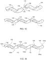
- Fig. 8 shows two strands 128 and 130 of coupled links 106, with each strand having aligned protrusions 106b.
- the string 108 may be inserted through the holes of the aligned protrusions 106b to bind the links 106 together and provide them with support.
- the central portion 106e of the body 106a of the link 106 (e.g., first link) is configured to extend about the central axis A-A in spaced relation thereto.
- the first link 106 is connected to the string 108, the inner surface of the central portion 106e is visible and exposed, along with the string 108 extending between the protrusions 106b.
- a cavity 160 is defined between the inner surface of the central portion 106e and the protrusions 106b.
- a second link 106 can be nested over the exposed central portion 106e, such that the cavities 160 of both links oppositely face one another across the string 108, thereby surrounding and enclosing the cavities 160 of both links.
- its protrusions 106b will align with the protrusions 106b of the first link.
- FIG. 8 An example of such nesting is shown in Fig. 8 , where the upper strand 128 of connected links 106 and the lower strand 130 of connected links 106 are shown with arrows indicating movement of portions of the strands 128 and 130 to relatively position the central portions 106e of respective links 106 to cover the exposed spaces on the inside of the central portions 106e of the links 106.
- the full cable 100 can be considered as being formed of the two strands 128 and 130, which become coiled around one another when the links 106 of the strands 128 and 130 nest into the spaces described above.
- each link 106 may define a longitudinally extending pin hole 136 at each end 142 and 144 of the body 106a.
- Each pin hole 136 is configured to receive a portion of a pin or peg 134.
- the pin or peg 134 is configured to be inserted through pin holes 136 to connect ends 142 and 144 together when they abut one another, which further connects the links 106 of the two strands 128 and 130 together, as shown in Fig. 10 .
- the hole 136 and pin or peg 134 in each end 142 and 144 are aligned with one another when the ends 142 and 144 of the links abut.
- the pins or pegs 134 can increase stability of the cable 100 and can further reduce gapping between the links 106.
- the ends 142 and 144 of the body 106a of link 106 may have, respectively, concave and convex (i.e., crescent-shaped) end surfaces 142a and 144a.
- concave and convex i.e., crescent-shaped end surfaces 142a and 144a.
- an interface or joint 150 formed therebetween permits some degree of relative movement and flexure between the two links 106, while minimizing gapping therebetween.
- the concave and convex surfaces provide complementary mating surfaces that allow some amount of pivoting and sliding across the interface 150 between to provide flexure or relative movement between the connected links 106.
Landscapes
- Engineering & Computer Science (AREA)
- Mechanical Engineering (AREA)
- Manufacturing & Machinery (AREA)
- Adornments (AREA)
- Ropes Or Cables (AREA)
Description
- The present invention relates to jewelry constructions, such as for bandable jewelry, including bracelets and necklaces. Specifically, the invention relates to jewelry constructions that permit flexibility.
- Jewelry beads are often strung on a string or wire, leaving the string visible due to large gaps between the beads.
-
US 5660036 describes a jewelry rope chain ,according to the preamble ofclaim 1, formed of a number of links of wire of a cross sectional configuration. The links are tightly interfit one into the other so as to be intertwined and fit one against the other to form an outward appearance of a double helix. The links generally have a small gap formed within their periphery to enable one of the other links to pass through the gap. A number of links are interconnected in accordance with particular ratios and thereafter a group is formed together. A new group is then begun interconnected to the old group and again the group is repeated. - The present invention provides a flexible cable as defined in appended
claim 1. Optional features are defined in the dependent claims. The flexible cable includes interconnected links, which, when connected together and strung on a string, forms a cable having the appearance of a fully three-dimensional helical surface resembling a rope or cable. - The flexible cable includes a plurality of helical links. Each link has a helical body that extends a single 360 degree revolution about a central axis of the link. Also, each link includes a plurality of male protrusions extending from the body at or near ends of the link. The protrusions extend inwardly toward the central axis. A hole is formed in the center of each protrusion. The hole is coaxial with the body. Also, the body defines a plurality of female recesses that each correspond to one protrusion. The recesses are located at or near the ends of the link, and may be adjacent to each corresponding protrusion. Each recess of a first one of the links is configured to receive a protrusion of a second one of the links and align the hole of the received protrusion with the central axis of the first link and with the center of a hole of a protrusion of the first link that is adjacent to the received protrusion. The system also includes a string or wire extending through the aligned holes of the protrusions of the first and second links.
- For each link, a central portion of the body is located between the protrusions and recesses at the ends of the link. The central portion of the body is configured to extend about the central axis in spaced relation thereto. An inner facing (relative to the central axis) side of the central portion defines part of a cavity between the ends of the link. A third one of the links can be nested into the cavity of a first of the links so that the inner facing side of the third link oppositely faces the inner facing side of the first link to thereby enclose the central axis and complete a segment of a fully round cable. The inner facing side of the central portion of each link may define a groove that extending parallel to the central axis. The grooves of each link longitudinally align with one another along the central axis to define a channel or lumen through which the string or cable extends between the protrusions of each link.
- The ends of the links may be crescent-shaped. In one embodiment, each link has a first end that has a concave end surface and a second end that has a convex end surface. When a concave end surface of a first link is connected adjacent to a convex end surface of a second link, the assembled links are permitted some degree of relative movement across an interface between the concave and convex end surfaces, while minimizing gapping therebetween, which would reveal the string or wire.
When the links are assembled together and strung on the string, all parting lines between the links will be located on one side (i.e., a back side) of the cable, giving the appearance of an unbroken twisted cable when viewed from the opposite side (i.e., a front display side) of the cable. Gemstones can be set into the outer side of each link very close to the sides of the link and along substantially the entire length of the link. Once assembled into a cable, the unbroken appearance of the cable gives the appearance of gemstones extending about the entire surface of the cable without interruption. -
-
Fig. 1 shows a front view of a flexible cable constructed in accordance with an aspect of the disclosure. -
Fig. 2 shows a rear view of the flexible cable ofFig. 1 . -
Fig. 3A shows the front side of a portion of the cable ofFig. 1 when flexed in a first direction along the length of the portion. -
Fig. 3B shows the front side of the portion of the cable ofFig. 3A when in an unflexed condition. -
Fig. 3C shows the front side of the portion of the cable ofFig. 3A when flexed in a second direction opposite to that inFig. 3A . -
Fig. 4A shows the rear side of a portion of the cable ofFig. 1 when flexed along the length of the portion. -
Fig. 4B shows the rear side of the portion of the cable ofFig. 4A when in an unflexed condition. -
Fig. 4C shows the rear side of the portion of the cable ofFig. 4A when flexed in a second direction opposite to that inFig. 4A . -
Fig. 5 shows a portion of an alternate embodiment of the links of the cable ofFig. 1 with gemstones set into links. -
Figs. 6A and 6B show one of the links of the cable ofFig. 1 viewed respectively from a front (top) and rear (bottom) side. -
Fig. 7 shows details of mating features of two of the links shown inFigs. 6A and 6B . -
Fig. 8 shows two strands of connected links being combined together to form the cable. -
Fig. 9 shows a portion of the cable ofFig. 1 after the two strands ofFig. 8 are intertwined together. -
Fig. 10 shows the placement of a pin or coupling element connecting ends of a pair of links together. -
Fig. 11 shows further details of mating surfaces between ends of links. -
Figs. 1 and 2 show aflexible jewelry cable 100, which can have connectors (not shown) at itsends flexible cable 100, which includes a plurality ofhelical links 106, which are interconnected together, and to a string 108 (Figs. 3 and 4 ) that extends through and between thelinks 106. Thus, theflexible cable 100 can be considered as having a modular construction, where each link 106 can be considered to be a module having certain common connecting features (described in greater detail below) that allow the links to be assembled together into a unitary cable. - As shown in
Figs. 1 and 2 , when the links are coupled together and fully assembled about thestring 108, they form thecable 100 which has a three-dimensional helical surface that continues all the way around (360 degrees) thecable 100 so there are no discontinuous flat spots on the sides or back of thecable 100. As shown in the exploded inset inFig. 1 , on the front side of thecable 100, there are no parting lines between thelinks 106, while in the exploded inset inFig. 2 , the only parting lines 110 evident are located on the back side of thecable 100. In view of this construction, a visual appearance of a continuous cable is presented when the cable is looped and worn with the front or display side facing out. - The specific modular construction of the
cable 100 is useful for permitting thecable 100 to flex a certain amount while simultaneously concealing the string orstring 108 that extends through thelinks 106.Figs. 3 and 4 show, respectively, front and rear views of a portion of thecable 100 ofFig. 1 when the cable is flexed.Figs. 3A to 4C show that there is minimal gapping between theadjacent links 106 when the cable is flexed. This minimal gapping aids in concealing thestring 108 from view. - In addition to the foregoing features, the near-continuous surface of the
cable 100 provides a large surface area that allows for gemstones to be inset or otherwise located on all sides of the cable for a continuous appearance as well. For example,Fig. 5 shows an alternate embodiment oflinks 206, which includegemstones 216 set into the outer surface of thelinks 206. Inlinks 206, three rows ofgemstones 216 are shown set into eachlink 206. Of course, the number of gemstones and their arrangement on thelinks 206 can vary from that shown inFig. 5 , and such variation may be based on the relative size of the surface area of the outside of thelink 206 and the size of thegemstones 216. -
Figs. 6A and 6B show a representative one of the plurality oflinks 106 of thecable 100 connected to astring 108. As used herein, astring 108 may be any single or multifilamentary material made, leather, fabric, or polymer that is capable of bending and flexing into a loop without breaking. If made of metal, the metal may be made of precious metal or non-precious metal. A string may include a wire, cable, or a chain. Thelinks 106 may be made of precious metals, such as gold, silver, and platinum, or non-precious metals. Also, at least a portion of the links, such as their outer surface, may bear indicia (such as text or logos) and/or may be colorized, such as by being plated, painted, or enameled in various colors. Thus, due to the modular construction of thecable 100 various combinations oflinks 106 of different metals or colors can be made to form various cable designs. - Each
link 106 has ahelical body 106a that extends a single 360 degree revolution about a central axis A-A of thelink 106. Thebody 106a extends from afirst end 142 to asecond end 144. The body has aninner surface 152 facing the central axis A-A, and anouter surface 154 facing outward with respect to the central axis A-A. Thelink 106 includes a plurality ofmale protrusions 106b at or near ends 142 and 144 of the link. Theprotrusions 106b extend radially toward the central axis from theinner surface 152 of thebody 106a. Eachprotrusion 106b defines a throughhole 106c that is coaxially aligned with thebody 106a and which is configured to receive thestring 108. The diameter of thehole 106c may be slightly larger than the diameter of thestring 108 to permit relative movement between theprotrusion 106b and thestring 108. - Also, the
body 106a defines a plurality offemale recesses 106d on the inner surface of thebody 106a, each of which corresponds to onemale protrusion 106b of thelink 106. Therecesses 106d are located at or near theends link 106, and therecesses 106d may be adjacent to theircorresponding protrusions 106b. - Thus, pairs of
recesses 106d andmale protrusions 106b may be located at theends body 106, and such pairs are spaced from each other by acentral portion 106e of the body. On the interior surface of thecentral portion 106e there is formed a depression orgroove 106f that extends longitudinally along axis A-A and which provides clearance for thestring 108 to pass between theprotrusions 106b. - As shown in
Fig. 7 , eachrecess 106d of a first one of thelinks 106 is configured to receive aprotrusion 106b of a second one of thelinks 106 to align thehole 106c of the receivedprotrusion 106b with the central axis of thefirst link 106 and with the center of ahole 106c of aprotrusion 106b of the first link that is adjacent to the receivedprotrusion 106b. -
Fig. 8 shows twostrands links 106, with each strand having alignedprotrusions 106b. When thelinks 106 are coupled together, and the protrusions are aligned, thestring 108 may be inserted through the holes of the alignedprotrusions 106b to bind thelinks 106 together and provide them with support. - Turning now momentarily back to
Fig. 6A , thecentral portion 106e of thebody 106a of the link 106 (e.g., first link) is configured to extend about the central axis A-A in spaced relation thereto. As shown inFig. 6B , when thefirst link 106 is connected to thestring 108, the inner surface of thecentral portion 106e is visible and exposed, along with thestring 108 extending between theprotrusions 106b. Indeed, inFig. 6B a cavity 160 is defined between the inner surface of thecentral portion 106e and theprotrusions 106b. To cover the cavity 160, asecond link 106 can be nested over the exposedcentral portion 106e, such that the cavities 160 of both links oppositely face one another across thestring 108, thereby surrounding and enclosing the cavities 160 of both links. When thesecond link 106 is so placed, itsprotrusions 106b will align with theprotrusions 106b of the first link. - An example of such nesting is shown in
Fig. 8 , where theupper strand 128 ofconnected links 106 and thelower strand 130 ofconnected links 106 are shown with arrows indicating movement of portions of thestrands central portions 106e ofrespective links 106 to cover the exposed spaces on the inside of thecentral portions 106e of thelinks 106. It will be appreciated that thefull cable 100 can be considered as being formed of the twostrands links 106 of thestrands links 106 of bothstrands protrusions 106b of thelinks 106 of bothstrands string 108 can be introduced through all of theholes 106c in theprotrusions 106b, as shown inFig. 9 , to thereby string all of the links together forming thecable 100. - When the
links 106 of thestrands ends bodies 106a of thelinks 106 ofstrand 128 abut theends bodies 106a of thelinks 106 ofstrand 130. Thebody 106a of eachlink 106 may define a longitudinally extendingpin hole 136 at eachend body 106a. Eachpin hole 136 is configured to receive a portion of a pin or peg 134. The pin or peg 134 is configured to be inserted throughpin holes 136 to connect ends 142 and 144 together when they abut one another, which further connects thelinks 106 of the twostrands Fig. 10 . As shown inFig. 10 , thehole 136 and pin or peg 134 in eachend cable 100 and can further reduce gapping between thelinks 106. - As shown in greater detail in
Fig. 11 , theends body 106a oflink 106 may have, respectively, concave and convex (i.e., crescent-shaped)end surfaces first link 106 having afirst end 142 with aconcave end surface 142a is connected adjacent to asecond link 106 having asecond end 144 with aconvex end surface 144a, an interface or joint 150 formed therebetween permits some degree of relative movement and flexure between the twolinks 106, while minimizing gapping therebetween. Indeed, the concave and convex surfaces provide complementary mating surfaces that allow some amount of pivoting and sliding across theinterface 150 between to provide flexure or relative movement between theconnected links 106. - There have been described and illustrated herein several embodiments of a flexible cable and a method of making the cable. While particular embodiments of the invention have been described, it is not intended that the invention be limited thereto, as the scope of the invention is defined by the appended claims. Thus, while particular materials have been disclosed for the construction of the cable, it will be appreciated that other suitable materials may be used as well. In addition, while particular connection types between the parts of the cable have been disclosed, it will be understood that other suitable connection types can be used. For example, and not by way of limitation, the links may employ a snap-fit ball and socket connection between the links. It will therefore be appreciated by those skilled in the art that yet other modifications could be made to the provided invention without deviating from scope as claimed.
Claims (8)
- A flexible cable (100) comprising:
a plurality of helical links (106; 206), each link (106; 206) coupled to one another, and each link having:a body (106a) that extends helically about a central axis (A-A) of the link, the body (106a) having an inner surface (152) and an outer surface (154), characterized by further comprisinga male protrusion (106b) extending from the inner surface (152) of the body at both ends (142, 144) of the body, wherein each protrusion (106b) defines a hole (106c) formed through the protrusion, each hole (106c) being coaxial with the body, wherein the body (106a) defines a female recess (106d) on the inner surface (152) of the body corresponding to each protrusion (106b), the recesses (106d) located at both ends (142, 144) of the body,wherein the body (106a) has a central portion (106e) located on the inner surface (152) between the pairs of protrusions and recesses (106b, 106d), the central portion (106e) extending about the central axis (A-A) and being spaced therefrom and having a cavity (160) defined between the pairs of protrusions and recesses (106b, 106d); anda string (108) extending through the holes (106c) formed through each protrusion and coupling the plurality of links (106; 206). - The cable (100) according to claim 1, wherein:
the plurality of links (106; 206) includes at least a first link, a second link, and a third link, and wherein one of the recesses (106d) of the first link is configured to receive one of the protrusions (106b) of the second link and thereby align the hole (106c) of the received protrusion of the second link with the hole (106c) of one of the protrusions of the first link. - The cable (100) according to claim 2, wherein:
the cavity (160) of the third link is configured to oppositely face and align with either of the cavity (160) of the first link or the cavity (160) of the second link to thereby surround and enclose the central axis (A-A) between the third link and either of the first link or the second link and to align the protrusions (106d) of the third link with the protrusions (106d) of either of the first link or the second link along the central axis (A-A), wherein the string (108)extends through the holes (106c) of the aligned protrusions (106d). - The cable (100) according to claim 1, wherein the central portion (106e) defines a groove (106f) that extends parallel to the central axis (A-A).
- The cable (100) according to claim 4, wherein the grooves (106f) of coupled links (106; 206) are configured to align along the central axis (A-A) and define a channel or lumen aligned with the protrusions (106d) of respective links through which the string (108) extends.
- The cable (100) according to claim 1, wherein the body (106a) has a first end (142) having a concave end surface (142a) and a second end (144) having a convex end surface (144a) which is a complementary mating surface to the concave end surface (142a).
- The cable (100) according to claim 6, wherein each link (106; 206) defines a longitudinally extending pin hole (136) formed in the first (142) and second ends (144) of the body, wherein the cable further includes:
a pin (134) received in the pin holes to connect pairs of the links (106; 206) together. - The cable (100) according to claim 7, wherein the pin hole (136) formed in the first end (142) of the body of the first link is configured to align with the pin hole (136) formed in the second end (144) of the body of the second link, and wherein one pin (134) extends through both the pin hole (136) formed in the first end (142) of the body of the first link and the pin hole (136) formed in the second end (144) of the body of the second link.
Applications Claiming Priority (2)
| Application Number | Priority Date | Filing Date | Title |
|---|---|---|---|
| US201862725498P | 2018-08-31 | 2018-08-31 | |
| PCT/US2019/049147 WO2020047464A1 (en) | 2018-08-31 | 2019-08-30 | Jewelry cable |
Publications (3)
| Publication Number | Publication Date |
|---|---|
| EP3817617A1 EP3817617A1 (en) | 2021-05-12 |
| EP3817617A4 EP3817617A4 (en) | 2021-11-03 |
| EP3817617B1 true EP3817617B1 (en) | 2022-07-06 |
Family
ID=69644645
Family Applications (1)
| Application Number | Title | Priority Date | Filing Date |
|---|---|---|---|
| EP19854403.3A Not-in-force EP3817617B1 (en) | 2018-08-31 | 2019-08-30 | Jewelry cable |
Country Status (6)
| Country | Link |
|---|---|
| US (1) | US11160336B2 (en) |
| EP (1) | EP3817617B1 (en) |
| CN (1) | CN112996410A (en) |
| CA (1) | CA3110562C (en) |
| ES (1) | ES2928373T3 (en) |
| WO (1) | WO2020047464A1 (en) |
Families Citing this family (2)
| Publication number | Priority date | Publication date | Assignee | Title |
|---|---|---|---|---|
| US20240180302A1 (en) * | 2020-01-14 | 2024-06-06 | Chrysos S.P.A | Elements for trinkets |
| US20260020549A1 (en) * | 2024-07-16 | 2026-01-22 | Travis McClure | Fishing lure |
Family Cites Families (31)
| Publication number | Priority date | Publication date | Assignee | Title |
|---|---|---|---|---|
| US429978A (en) * | 1890-06-10 | Chain | ||
| US581852A (en) * | 1897-05-04 | Sprocket-chain | ||
| US1245965A (en) * | 1916-11-11 | 1917-11-06 | Henry B Pratt | Bead for necklaces and similar articles. |
| US1267544A (en) * | 1917-05-26 | 1918-05-28 | Non Skid Company Of America | Antiskid for wheels. |
| US1276117A (en) * | 1917-06-13 | 1918-08-20 | Rogers Motor Lock Company | Flexible armored conduit. |
| US1492014A (en) * | 1919-06-07 | 1924-04-29 | Benjamin Electric Mfg Co | Fixture chain |
| US1515499A (en) * | 1923-11-10 | 1924-11-11 | Providence Stock Company | Bead structure |
| US1702502A (en) * | 1925-12-29 | 1929-02-19 | Jr Henry D Olier | Supporting chain for electrical conductors |
| DE459114C (en) | 1927-01-13 | 1928-04-30 | Charles Holl | Articulated connection, especially for link bracelets and similar jewelry |
| US1668359A (en) * | 1927-07-28 | 1928-05-01 | Parks Bros Rogers Inc | Flexible chain |
| US1894195A (en) * | 1932-04-26 | 1933-01-10 | Harold L Pulver | Ornamental bead chain |
| CH265605A (en) | 1947-12-11 | 1949-12-15 | Manuf Genevoise De Boites De M | Ribbon with articulated elements. |
| US3135086A (en) | 1961-02-13 | 1964-06-02 | Shibuya Tetsuzo | Expansible linkage |
| US4238935A (en) * | 1977-08-23 | 1980-12-16 | Oudet Jean Marie P | Method for manufacturing a chain from the vertebra of an animal |
| JPS60184440A (en) | 1984-03-01 | 1985-09-19 | Manabu Kiuchi | Mesh band |
| US4594847A (en) * | 1984-08-20 | 1986-06-17 | E.H. Ashley & Company, Inc. | Detachably interconnectable chain link and chain constructed therewith |
| US5197767A (en) * | 1985-04-09 | 1993-03-30 | Tsubakimoto Chain Co. | Flexible supporting sheath for cables and the like |
| US5074127A (en) * | 1989-11-30 | 1991-12-24 | Yurman David N | Highly flexible jewelry band material |
| IL92607A (en) * | 1989-12-08 | 1991-09-16 | Rozenwasser David | Fine jewelry rope chain |
| US5636549A (en) * | 1993-12-22 | 1997-06-10 | Hughes Electronics | Wire wound threaded elements including lead screws, roller not assemblies and process |
| US5660036A (en) | 1994-12-12 | 1997-08-26 | Rozenwasser; David | Jewelry rope chain |
| US6108961A (en) | 1998-05-13 | 2000-08-29 | Milawski; Scott J. | Twisted, spinning fishing lure and counterweight |
| KR100288485B1 (en) * | 1998-09-17 | 2001-05-02 | 신종화 | Ornaments for ornaments |
| US6209306B1 (en) * | 1999-04-07 | 2001-04-03 | Meang K. Chia | Decorative jewelry rope chain |
| US6481196B1 (en) | 1999-04-07 | 2002-11-19 | Meang K. Chia | Length of jewelry rope chain exhibiting distinctive visual properties, and related method of manufacture |
| US6158206A (en) * | 1999-08-17 | 2000-12-12 | D&W Jewelry, Inc. | Modified gap for jewelry rope chain link |
| KR100463458B1 (en) * | 2002-04-23 | 2004-12-29 | 김익수 | Chain for Accessories and Producing Method thereof |
| US20060265878A1 (en) | 2005-05-11 | 2006-11-30 | Jacqueline Zorman | Sports ball novelty item and method for forming |
| JP4266042B2 (en) * | 2007-02-21 | 2009-05-20 | 株式会社シンテック | Linear member, method for manufacturing linear member, and accessory |
| US7841129B2 (en) | 2008-10-08 | 2010-11-30 | Blackshear Jr C Walter W | Snag-proof multi-purpose fishing tackle |
| US8595907B2 (en) | 2010-08-09 | 2013-12-03 | Michael Katz | Aesthetic beaded necklace clasp |
-
2019
- 2019-08-30 CA CA3110562A patent/CA3110562C/en active Active
- 2019-08-30 US US17/271,983 patent/US11160336B2/en active Active
- 2019-08-30 CN CN201980056336.0A patent/CN112996410A/en active Pending
- 2019-08-30 WO PCT/US2019/049147 patent/WO2020047464A1/en not_active Ceased
- 2019-08-30 EP EP19854403.3A patent/EP3817617B1/en not_active Not-in-force
- 2019-08-30 ES ES19854403T patent/ES2928373T3/en active Active
Also Published As
| Publication number | Publication date |
|---|---|
| US20210244139A1 (en) | 2021-08-12 |
| EP3817617A4 (en) | 2021-11-03 |
| ES2928373T3 (en) | 2022-11-17 |
| EP3817617A1 (en) | 2021-05-12 |
| WO2020047464A1 (en) | 2020-03-05 |
| CN112996410A (en) | 2021-06-18 |
| US11160336B2 (en) | 2021-11-02 |
| CA3110562C (en) | 2021-11-09 |
| CA3110562A1 (en) | 2020-03-05 |
Similar Documents
| Publication | Publication Date | Title |
|---|---|---|
| CA3110562C (en) | Jewelry cable | |
| US20140182332A1 (en) | Piece Of Jewelry | |
| CN111067203B (en) | Articulated chain with concealed hinge | |
| US12004609B2 (en) | Component and method for assembling a jewelry item | |
| US7472564B2 (en) | Necklace or bracelet with regularly spaced links on a flexible connecting member. | |
| CN110545690B (en) | accessories | |
| US20240324736A1 (en) | Jewelry link | |
| HK40046122A (en) | Jewelry cable | |
| CN111166020B (en) | Assembly consisting of elements such as links of a chain | |
| US10881172B1 (en) | Jewelry link assembly and a method of assembling jewelry chain links | |
| CN1069401A (en) | jewelry connector | |
| US20120073325A1 (en) | Ornamental article of jewelry | |
| US7343729B2 (en) | Simulated chains with flexible sections | |
| KR20110105517A (en) | Fastening structure of the connector for jewelry | |
| US4245461A (en) | Non-expansible linkage bracelet and method of manufacture thereof | |
| JP3111643U (en) | Decorative chain elements in jewelry chains | |
| KR200293747Y1 (en) | A parts connector for necklace | |
| USRE31681E (en) | Non-expansible linkage bracelet and method of manufacture thereof | |
| JP5128218B2 (en) | Decorative piece | |
| CA1271923A (en) | Clasp with interchangeable ornament | |
| KR200324782Y1 (en) | A ring | |
| KR200298510Y1 (en) | personal ornaments | |
| CN2334217Y (en) | Bullet type wrist-watch strap | |
| GB2256575A (en) | Preventing expansion of expandable wrist-bands | |
| KR20110105518A (en) | Fastening structure of the connector for jewelry |
Legal Events
| Date | Code | Title | Description |
|---|---|---|---|
| STAA | Information on the status of an ep patent application or granted ep patent |
Free format text: STATUS: THE INTERNATIONAL PUBLICATION HAS BEEN MADE |
|
| PUAI | Public reference made under article 153(3) epc to a published international application that has entered the european phase |
Free format text: ORIGINAL CODE: 0009012 |
|
| STAA | Information on the status of an ep patent application or granted ep patent |
Free format text: STATUS: REQUEST FOR EXAMINATION WAS MADE |
|
| 17P | Request for examination filed |
Effective date: 20210205 |
|
| AK | Designated contracting states |
Kind code of ref document: A1 Designated state(s): AL AT BE BG CH CY CZ DE DK EE ES FI FR GB GR HR HU IE IS IT LI LT LU LV MC MK MT NL NO PL PT RO RS SE SI SK SM TR |
|
| A4 | Supplementary search report drawn up and despatched |
Effective date: 20211006 |
|
| RIC1 | Information provided on ipc code assigned before grant |
Ipc: A44C 13/00 20060101ALI20210930BHEP Ipc: B21L 11/00 20060101ALI20210930BHEP Ipc: B21L 5/00 20060101ALI20210930BHEP Ipc: A44C 27/00 20060101ALI20210930BHEP Ipc: A44C 5/00 20060101ALI20210930BHEP Ipc: A44C 11/00 20060101ALI20210930BHEP Ipc: A44C 5/02 20060101AFI20210930BHEP |
|
| DAV | Request for validation of the european patent (deleted) | ||
| DAX | Request for extension of the european patent (deleted) | ||
| GRAP | Despatch of communication of intention to grant a patent |
Free format text: ORIGINAL CODE: EPIDOSNIGR1 |
|
| STAA | Information on the status of an ep patent application or granted ep patent |
Free format text: STATUS: GRANT OF PATENT IS INTENDED |
|
| INTG | Intention to grant announced |
Effective date: 20220225 |
|
| GRAS | Grant fee paid |
Free format text: ORIGINAL CODE: EPIDOSNIGR3 |
|
| GRAA | (expected) grant |
Free format text: ORIGINAL CODE: 0009210 |
|
| STAA | Information on the status of an ep patent application or granted ep patent |
Free format text: STATUS: THE PATENT HAS BEEN GRANTED |
|
| AK | Designated contracting states |
Kind code of ref document: B1 Designated state(s): AL AT BE BG CH CY CZ DE DK EE ES FI FR GB GR HR HU IE IS IT LI LT LU LV MC MK MT NL NO PL PT RO RS SE SI SK SM TR |
|
| REG | Reference to a national code |
Ref country code: AT Ref legal event code: REF Ref document number: 1502218 Country of ref document: AT Kind code of ref document: T Effective date: 20220715 Ref country code: CH Ref legal event code: EP |
|
| REG | Reference to a national code |
Ref country code: DE Ref legal event code: R096 Ref document number: 602019016836 Country of ref document: DE |
|
| REG | Reference to a national code |
Ref country code: IE Ref legal event code: FG4D |
|
| REG | Reference to a national code |
Ref country code: LT Ref legal event code: MG9D |
|
| REG | Reference to a national code |
Ref country code: NL Ref legal event code: MP Effective date: 20220706 |
|
| REG | Reference to a national code |
Ref country code: ES Ref legal event code: FG2A Ref document number: 2928373 Country of ref document: ES Kind code of ref document: T3 Effective date: 20221117 |
|
| PG25 | Lapsed in a contracting state [announced via postgrant information from national office to epo] |
Ref country code: SE Free format text: LAPSE BECAUSE OF FAILURE TO SUBMIT A TRANSLATION OF THE DESCRIPTION OR TO PAY THE FEE WITHIN THE PRESCRIBED TIME-LIMIT Effective date: 20220706 Ref country code: RS Free format text: LAPSE BECAUSE OF FAILURE TO SUBMIT A TRANSLATION OF THE DESCRIPTION OR TO PAY THE FEE WITHIN THE PRESCRIBED TIME-LIMIT Effective date: 20220706 Ref country code: PT Free format text: LAPSE BECAUSE OF FAILURE TO SUBMIT A TRANSLATION OF THE DESCRIPTION OR TO PAY THE FEE WITHIN THE PRESCRIBED TIME-LIMIT Effective date: 20221107 Ref country code: NO Free format text: LAPSE BECAUSE OF FAILURE TO SUBMIT A TRANSLATION OF THE DESCRIPTION OR TO PAY THE FEE WITHIN THE PRESCRIBED TIME-LIMIT Effective date: 20221006 Ref country code: NL Free format text: LAPSE BECAUSE OF FAILURE TO SUBMIT A TRANSLATION OF THE DESCRIPTION OR TO PAY THE FEE WITHIN THE PRESCRIBED TIME-LIMIT Effective date: 20220706 Ref country code: LV Free format text: LAPSE BECAUSE OF FAILURE TO SUBMIT A TRANSLATION OF THE DESCRIPTION OR TO PAY THE FEE WITHIN THE PRESCRIBED TIME-LIMIT Effective date: 20220706 Ref country code: LT Free format text: LAPSE BECAUSE OF FAILURE TO SUBMIT A TRANSLATION OF THE DESCRIPTION OR TO PAY THE FEE WITHIN THE PRESCRIBED TIME-LIMIT Effective date: 20220706 Ref country code: FI Free format text: LAPSE BECAUSE OF FAILURE TO SUBMIT A TRANSLATION OF THE DESCRIPTION OR TO PAY THE FEE WITHIN THE PRESCRIBED TIME-LIMIT Effective date: 20220706 |
|
| REG | Reference to a national code |
Ref country code: AT Ref legal event code: MK05 Ref document number: 1502218 Country of ref document: AT Kind code of ref document: T Effective date: 20220706 |
|
| PG25 | Lapsed in a contracting state [announced via postgrant information from national office to epo] |
Ref country code: PL Free format text: LAPSE BECAUSE OF FAILURE TO SUBMIT A TRANSLATION OF THE DESCRIPTION OR TO PAY THE FEE WITHIN THE PRESCRIBED TIME-LIMIT Effective date: 20220706 Ref country code: IS Free format text: LAPSE BECAUSE OF FAILURE TO SUBMIT A TRANSLATION OF THE DESCRIPTION OR TO PAY THE FEE WITHIN THE PRESCRIBED TIME-LIMIT Effective date: 20221106 Ref country code: HR Free format text: LAPSE BECAUSE OF FAILURE TO SUBMIT A TRANSLATION OF THE DESCRIPTION OR TO PAY THE FEE WITHIN THE PRESCRIBED TIME-LIMIT Effective date: 20220706 Ref country code: GR Free format text: LAPSE BECAUSE OF FAILURE TO SUBMIT A TRANSLATION OF THE DESCRIPTION OR TO PAY THE FEE WITHIN THE PRESCRIBED TIME-LIMIT Effective date: 20221007 |
|
| REG | Reference to a national code |
Ref country code: CH Ref legal event code: PL |
|
| REG | Reference to a national code |
Ref country code: DE Ref legal event code: R097 Ref document number: 602019016836 Country of ref document: DE |
|
| PG25 | Lapsed in a contracting state [announced via postgrant information from national office to epo] |
Ref country code: SM Free format text: LAPSE BECAUSE OF FAILURE TO SUBMIT A TRANSLATION OF THE DESCRIPTION OR TO PAY THE FEE WITHIN THE PRESCRIBED TIME-LIMIT Effective date: 20220706 Ref country code: RO Free format text: LAPSE BECAUSE OF FAILURE TO SUBMIT A TRANSLATION OF THE DESCRIPTION OR TO PAY THE FEE WITHIN THE PRESCRIBED TIME-LIMIT Effective date: 20220706 Ref country code: MC Free format text: LAPSE BECAUSE OF FAILURE TO SUBMIT A TRANSLATION OF THE DESCRIPTION OR TO PAY THE FEE WITHIN THE PRESCRIBED TIME-LIMIT Effective date: 20220706 Ref country code: LU Free format text: LAPSE BECAUSE OF NON-PAYMENT OF DUE FEES Effective date: 20220830 Ref country code: LI Free format text: LAPSE BECAUSE OF NON-PAYMENT OF DUE FEES Effective date: 20220831 Ref country code: DK Free format text: LAPSE BECAUSE OF FAILURE TO SUBMIT A TRANSLATION OF THE DESCRIPTION OR TO PAY THE FEE WITHIN THE PRESCRIBED TIME-LIMIT Effective date: 20220706 Ref country code: CZ Free format text: LAPSE BECAUSE OF FAILURE TO SUBMIT A TRANSLATION OF THE DESCRIPTION OR TO PAY THE FEE WITHIN THE PRESCRIBED TIME-LIMIT Effective date: 20220706 Ref country code: CH Free format text: LAPSE BECAUSE OF NON-PAYMENT OF DUE FEES Effective date: 20220831 Ref country code: AT Free format text: LAPSE BECAUSE OF FAILURE TO SUBMIT A TRANSLATION OF THE DESCRIPTION OR TO PAY THE FEE WITHIN THE PRESCRIBED TIME-LIMIT Effective date: 20220706 |
|
| REG | Reference to a national code |
Ref country code: BE Ref legal event code: MM Effective date: 20220831 |
|
| PLBE | No opposition filed within time limit |
Free format text: ORIGINAL CODE: 0009261 |
|
| STAA | Information on the status of an ep patent application or granted ep patent |
Free format text: STATUS: NO OPPOSITION FILED WITHIN TIME LIMIT |
|
| PG25 | Lapsed in a contracting state [announced via postgrant information from national office to epo] |
Ref country code: SK Free format text: LAPSE BECAUSE OF FAILURE TO SUBMIT A TRANSLATION OF THE DESCRIPTION OR TO PAY THE FEE WITHIN THE PRESCRIBED TIME-LIMIT Effective date: 20220706 Ref country code: EE Free format text: LAPSE BECAUSE OF FAILURE TO SUBMIT A TRANSLATION OF THE DESCRIPTION OR TO PAY THE FEE WITHIN THE PRESCRIBED TIME-LIMIT Effective date: 20220706 |
|
| 26N | No opposition filed |
Effective date: 20230411 |
|
| PG25 | Lapsed in a contracting state [announced via postgrant information from national office to epo] |
Ref country code: AL Free format text: LAPSE BECAUSE OF FAILURE TO SUBMIT A TRANSLATION OF THE DESCRIPTION OR TO PAY THE FEE WITHIN THE PRESCRIBED TIME-LIMIT Effective date: 20220706 |
|
| PG25 | Lapsed in a contracting state [announced via postgrant information from national office to epo] |
Ref country code: IE Free format text: LAPSE BECAUSE OF NON-PAYMENT OF DUE FEES Effective date: 20220830 |
|
| PG25 | Lapsed in a contracting state [announced via postgrant information from national office to epo] |
Ref country code: SI Free format text: LAPSE BECAUSE OF FAILURE TO SUBMIT A TRANSLATION OF THE DESCRIPTION OR TO PAY THE FEE WITHIN THE PRESCRIBED TIME-LIMIT Effective date: 20220706 |
|
| PG25 | Lapsed in a contracting state [announced via postgrant information from national office to epo] |
Ref country code: BE Free format text: LAPSE BECAUSE OF NON-PAYMENT OF DUE FEES Effective date: 20220831 |
|
| PGFP | Annual fee paid to national office [announced via postgrant information from national office to epo] |
Ref country code: IT Payment date: 20230810 Year of fee payment: 5 Ref country code: GB Payment date: 20230818 Year of fee payment: 5 Ref country code: ES Payment date: 20230905 Year of fee payment: 5 |
|
| PGFP | Annual fee paid to national office [announced via postgrant information from national office to epo] |
Ref country code: FR Payment date: 20230809 Year of fee payment: 5 Ref country code: DE Payment date: 20230811 Year of fee payment: 5 |
|
| PG25 | Lapsed in a contracting state [announced via postgrant information from national office to epo] |
Ref country code: CY Free format text: LAPSE BECAUSE OF FAILURE TO SUBMIT A TRANSLATION OF THE DESCRIPTION OR TO PAY THE FEE WITHIN THE PRESCRIBED TIME-LIMIT Effective date: 20220706 |
|
| PG25 | Lapsed in a contracting state [announced via postgrant information from national office to epo] |
Ref country code: MK Free format text: LAPSE BECAUSE OF FAILURE TO SUBMIT A TRANSLATION OF THE DESCRIPTION OR TO PAY THE FEE WITHIN THE PRESCRIBED TIME-LIMIT Effective date: 20220706 Ref country code: HU Free format text: LAPSE BECAUSE OF FAILURE TO SUBMIT A TRANSLATION OF THE DESCRIPTION OR TO PAY THE FEE WITHIN THE PRESCRIBED TIME-LIMIT; INVALID AB INITIO Effective date: 20190830 |
|
| PG25 | Lapsed in a contracting state [announced via postgrant information from national office to epo] |
Ref country code: TR Free format text: LAPSE BECAUSE OF FAILURE TO SUBMIT A TRANSLATION OF THE DESCRIPTION OR TO PAY THE FEE WITHIN THE PRESCRIBED TIME-LIMIT Effective date: 20220706 |
|
| PG25 | Lapsed in a contracting state [announced via postgrant information from national office to epo] |
Ref country code: BG Free format text: LAPSE BECAUSE OF FAILURE TO SUBMIT A TRANSLATION OF THE DESCRIPTION OR TO PAY THE FEE WITHIN THE PRESCRIBED TIME-LIMIT Effective date: 20220706 |
|
| PG25 | Lapsed in a contracting state [announced via postgrant information from national office to epo] |
Ref country code: MT Free format text: LAPSE BECAUSE OF FAILURE TO SUBMIT A TRANSLATION OF THE DESCRIPTION OR TO PAY THE FEE WITHIN THE PRESCRIBED TIME-LIMIT Effective date: 20220706 |
|
| REG | Reference to a national code |
Ref country code: DE Ref legal event code: R119 Ref document number: 602019016836 Country of ref document: DE |
|
| GBPC | Gb: european patent ceased through non-payment of renewal fee |
Effective date: 20240830 |
|
| PG25 | Lapsed in a contracting state [announced via postgrant information from national office to epo] |
Ref country code: DE Free format text: LAPSE BECAUSE OF NON-PAYMENT OF DUE FEES Effective date: 20250301 |
|
| PG25 | Lapsed in a contracting state [announced via postgrant information from national office to epo] |
Ref country code: GB Free format text: LAPSE BECAUSE OF NON-PAYMENT OF DUE FEES Effective date: 20240830 |
|
| PG25 | Lapsed in a contracting state [announced via postgrant information from national office to epo] |
Ref country code: IT Free format text: LAPSE BECAUSE OF NON-PAYMENT OF DUE FEES Effective date: 20240830 |
|
| PG25 | Lapsed in a contracting state [announced via postgrant information from national office to epo] |
Ref country code: FR Free format text: LAPSE BECAUSE OF NON-PAYMENT OF DUE FEES Effective date: 20240831 |
|
| REG | Reference to a national code |
Ref country code: ES Ref legal event code: FD2A Effective date: 20250929 |
|
| PG25 | Lapsed in a contracting state [announced via postgrant information from national office to epo] |
Ref country code: ES Free format text: LAPSE BECAUSE OF NON-PAYMENT OF DUE FEES Effective date: 20240831 |