EP3817356A1 - Bonded structure, imaging device, and moving body - Google Patents
Bonded structure, imaging device, and moving body Download PDFInfo
- Publication number
- EP3817356A1 EP3817356A1 EP19825661.2A EP19825661A EP3817356A1 EP 3817356 A1 EP3817356 A1 EP 3817356A1 EP 19825661 A EP19825661 A EP 19825661A EP 3817356 A1 EP3817356 A1 EP 3817356A1
- Authority
- EP
- European Patent Office
- Prior art keywords
- bonded structure
- support
- adhesive body
- facing
- adhesive
- Prior art date
- Legal status (The legal status is an assumption and is not a legal conclusion. Google has not performed a legal analysis and makes no representation as to the accuracy of the status listed.)
- Granted
Links
Images



Classifications
-
- B—PERFORMING OPERATIONS; TRANSPORTING
- B60—VEHICLES IN GENERAL
- B60R—VEHICLES, VEHICLE FITTINGS, OR VEHICLE PARTS, NOT OTHERWISE PROVIDED FOR
- B60R11/00—Arrangements for holding or mounting articles, not otherwise provided for
- B60R11/04—Mounting of cameras operative during drive; Arrangement of controls thereof relative to the vehicle
-
- G—PHYSICS
- G03—PHOTOGRAPHY; CINEMATOGRAPHY; ANALOGOUS TECHNIQUES USING WAVES OTHER THAN OPTICAL WAVES; ELECTROGRAPHY; HOLOGRAPHY
- G03B—APPARATUS OR ARRANGEMENTS FOR TAKING PHOTOGRAPHS OR FOR PROJECTING OR VIEWING THEM; APPARATUS OR ARRANGEMENTS EMPLOYING ANALOGOUS TECHNIQUES USING WAVES OTHER THAN OPTICAL WAVES; ACCESSORIES THEREFOR
- G03B17/00—Details of cameras or camera bodies; Accessories therefor
- G03B17/02—Bodies
-
- G—PHYSICS
- G02—OPTICS
- G02B—OPTICAL ELEMENTS, SYSTEMS OR APPARATUS
- G02B7/00—Mountings, adjusting means, or light-tight connections, for optical elements
- G02B7/02—Mountings, adjusting means, or light-tight connections, for optical elements for lenses
- G02B7/025—Mountings, adjusting means, or light-tight connections, for optical elements for lenses using glue
-
- G—PHYSICS
- G03—PHOTOGRAPHY; CINEMATOGRAPHY; ANALOGOUS TECHNIQUES USING WAVES OTHER THAN OPTICAL WAVES; ELECTROGRAPHY; HOLOGRAPHY
- G03B—APPARATUS OR ARRANGEMENTS FOR TAKING PHOTOGRAPHS OR FOR PROJECTING OR VIEWING THEM; APPARATUS OR ARRANGEMENTS EMPLOYING ANALOGOUS TECHNIQUES USING WAVES OTHER THAN OPTICAL WAVES; ACCESSORIES THEREFOR
- G03B17/00—Details of cameras or camera bodies; Accessories therefor
- G03B17/02—Bodies
- G03B17/12—Bodies with means for supporting objectives, supplementary lenses, filters, masks, or turrets
-
- G—PHYSICS
- G03—PHOTOGRAPHY; CINEMATOGRAPHY; ANALOGOUS TECHNIQUES USING WAVES OTHER THAN OPTICAL WAVES; ELECTROGRAPHY; HOLOGRAPHY
- G03B—APPARATUS OR ARRANGEMENTS FOR TAKING PHOTOGRAPHS OR FOR PROJECTING OR VIEWING THEM; APPARATUS OR ARRANGEMENTS EMPLOYING ANALOGOUS TECHNIQUES USING WAVES OTHER THAN OPTICAL WAVES; ACCESSORIES THEREFOR
- G03B30/00—Camera modules comprising integrated lens units and imaging units, specially adapted for being embedded in other devices, e.g. mobile phones or vehicles
-
- H—ELECTRICITY
- H04—ELECTRIC COMMUNICATION TECHNIQUE
- H04N—PICTORIAL COMMUNICATION, e.g. TELEVISION
- H04N23/00—Cameras or camera modules comprising electronic image sensors; Control thereof
- H04N23/50—Constructional details
- H04N23/54—Mounting of pick-up tubes, electronic image sensors, deviation or focusing coils
-
- H—ELECTRICITY
- H04—ELECTRIC COMMUNICATION TECHNIQUE
- H04N—PICTORIAL COMMUNICATION, e.g. TELEVISION
- H04N23/00—Cameras or camera modules comprising electronic image sensors; Control thereof
- H04N23/50—Constructional details
- H04N23/55—Optical parts specially adapted for electronic image sensors; Mounting thereof
-
- B—PERFORMING OPERATIONS; TRANSPORTING
- B60—VEHICLES IN GENERAL
- B60R—VEHICLES, VEHICLE FITTINGS, OR VEHICLE PARTS, NOT OTHERWISE PROVIDED FOR
- B60R11/00—Arrangements for holding or mounting articles, not otherwise provided for
- B60R2011/0001—Arrangements for holding or mounting articles, not otherwise provided for characterised by position
- B60R2011/0003—Arrangements for holding or mounting articles, not otherwise provided for characterised by position inside the vehicle
- B60R2011/0026—Windows, e.g. windscreen
-
- B—PERFORMING OPERATIONS; TRANSPORTING
- B64—AIRCRAFT; AVIATION; COSMONAUTICS
- B64D—EQUIPMENT FOR FITTING IN OR TO AIRCRAFT; FLIGHT SUITS; PARACHUTES; ARRANGEMENT OR MOUNTING OF POWER PLANTS OR PROPULSION TRANSMISSIONS IN AIRCRAFT
- B64D47/00—Equipment not otherwise provided for
- B64D47/08—Arrangements of cameras
Definitions
- the present disclosure relates to a bonded structure, an imaging apparatus, and a moveable body.
- a first member may be fixed to a second member.
- Adhesive may be used for the fixing to simplify production.
- PTL patent literature
- a bonded structure according to a first aspect includes:
- An imaging apparatus includes:
- a moveable body includes an imaging apparatus, the imaging apparatus including: a bonded structure that includes a first member; a second member including a facing surface facing the first member and a support including a side surface inclined outward as viewed from the first member; and an adhesive body positioned between the first member and the support, extending from the facing surface to the side surface, having a fillet shape at an end of the adhesive body by the side surface, and fixing the first member to the second member; an image sensor mounted on the first member; and an imaging optical system including at least one optical element and held by the second member so that an image is formed on an optical detection surface of the image sensor.
- the bonded structure according to an embodiment of the present disclosure is, for example, applied to an imaging apparatus.
- An imaging apparatus 10 to which the bonded structure according to the present embodiment is applied is, for example, mounted in a moveable body 11, as illustrated in FIG. 1 .
- the moveable body 11 may, for example, encompass vehicles, ships, and aircraft.
- Vehicles may, for example, include automobiles, industrial vehicles, railway vehicles, vehicles for daily life, and fixed-wing aircraft that run on a runway.
- Automobiles may, for example, include passenger vehicles, trucks, buses, motorcycles, and trolley buses.
- Industrial vehicles may, for example, include industrial vehicles for agriculture and for construction.
- Industrial vehicles may, for example, include forklifts and golf carts.
- Industrial vehicles for agriculture may, for example, include tractors, cultivators, transplanters, binders, combines, and lawnmowers.
- Industrial vehicles for construction may, for example, include bulldozers, scrapers, backhoes, cranes, dump cars, and road rollers.
- Vehicles may include man-powered vehicles.
- the types of vehicles are not limited to the above examples.
- automobiles may include industrial vehicles that can be driven on the road.
- the same vehicle may also be included in multiple categories.
- Ships may, for example, include marine jets, boats, and tankers.
- Aircraft may, for example, include fixed-wing aircraft and rotorcraft.
- the imaging apparatus 10 includes an imaging optical system 12, an image sensor 13, and a bonded structure 14.
- the imaging optical system 12 includes at least one optical element, such as a lens.
- the imaging optical system 12 is designed and formed so that optical properties such as angle of view and depth of field become desired values.
- the imaging optical system 12 is held by a second member 16, which forms part of the below-described bonded structure 14, so that a subject image is formed on the image sensor 13.
- the image sensor 13 is, for example, a charge coupled device (CCD) image sensor or a complementary metal oxide semiconductor (CMOS) image sensor.
- CCD charge coupled device
- CMOS complementary metal oxide semiconductor
- the image sensor 13 is mounted on a first member 15, which forms part of the below-described bonded structure 14.
- the image sensor 13 captures the subject image formed by the imaging optical system 12.
- the bonded structure 14 includes the first member 15, the second member 16, and an adhesive body 17.
- the first member 15 is a circuit board, for example, on which the image sensor 13 is mounted.
- the first member 15 may include a flat surface fs1, as illustrated in FIG. 3 .
- the first member 15 supports the image sensor 13 so that an optical detection surface of the image sensor 13 is parallel to the flat surface fs1.
- a side surface ss1 of the first member 15 may be perpendicular or inclined relative to the flat surface fs1.
- the side surface ss1 of the first member 15 in the bonded structure 14 may be positioned inward from the edge of the adhesive body 17 on the support 18 side of the second member 16, described below. Furthermore, as viewed from the perpendicular direction, the side surface ss1 of the first member 15 in the bonded structure 14 may be positioned inward from a side surface ss2 of the support 18, described below. Inward from the side surface ss2 refers to being on the inside of the boundary line between the side surface ss2 and a facing surface fs2 of the support 18, or being on the facing surface fs2 side of the boundary line.
- the second member 16 is a lens case holding the imaging optical system 12, for example, as described above.
- the second member 16 may, for example, be formed by molding a resin.
- the second member 16 may be cylindrical overall, for example, and may hold the imaging optical system 12 so that the optical axis OA of the imaging optical system 12 and the shaft core overlap.
- the second member 16 includes the support 18.
- the support 18 is, for example, formed around the shaft core. As illustrated in FIG. 3 , the support 18 includes the facing surface fs2 and the side surface ss2.
- the facing surface fs2 may include a flat surface perpendicular to the optical axis OA.
- the entire facing surface fs2 is perpendicular to the optical axis OA in the present embodiment.
- the facing surface fs2 faces the first member 15 in the bonded structure 14. Specifically, the facing surface fs2 may face the flat surface fs1 of the first member 15. The facing surface fs2 may be parallel to the flat surface fs1 of the first member 15.
- the side surface ss2 of the support 18 is inclined relative to the facing surface fs2 so as to spread outward as viewed from the direction perpendicular to the facing surface fs2.
- the side surface ss2 may be a flat surface, as illustrated in FIG. 3 .
- the angle formed between the facing surface fs2 and the side surface ss2 may be greater than 90 degrees and less than 170 degrees.
- the side surface ss2 may be a curved surface protruding outward, as illustrated in FIG. 4 .
- the side surface ss2 may be a curved surface recessed inward, as illustrated in FIG. 5 .
- the side surface ss2 may connect farther outward to a liquid retainer 19 when viewed in a direction perpendicular to the facing surface fs2, as illustrated in FIG. 3 .
- the liquid retainer 19 is, for example, at an angle of less than 180 degrees relative to the side surface ss2 and may be curved.
- the adhesive body 17 is positioned between the first member 15 and the support 18 and fixes the first member 15 to the second member 16, as illustrated in FIG. 6 .
- the adhesive body 17 extends along the support 18 in close contact from the facing surface fs2 to the side surface ss2.
- the adhesive body 17 has a fillet shape at an end thereof by the side surface ss2.
- the fillet shape is a shape that diverges in a direction perpendicular to the facing surface fs2 towards the end of the adhesive body 17 on the side surface ss2 side along a direction parallel to the facing surface fs2.
- the adhesive body 17 may extend from the portion of the flat surface fs1 of the first member 15 facing the facing surface fs2 to the side surface ss1 while in close contact.
- the adhesive body 17 may have a fillet shape at the end thereof by the side surface ss1.
- the adhesive body 17 is cured adhesive.
- a photocurable resin or a thermosetting resin, for example, may be used as the adhesive.
- the second member 16 is allowed to stand with the facing surface fs2 facing vertically upward, for example, as illustrated in FIG. 7 .
- the second member 16 may be allowed to stand with the facing surface fs2 facing vertically downward or in any other direction.
- Adhesive 20 is applied near the end of the facing surface fs2 by the side surface ss2.
- the first member 15 is aligned relative to the second member 16 along the flat surface fs1 with the flat surface fs1 facing the facing surface fs2 above the second member 16.
- the first member 15 is displaced vertically downward, as illustrated in FIG. 8 .
- the adhesive 20 is compressed between the flat surface fs1 of the first member 15 and the facing surface fs2 of the support 18 by the displacement of the first member 15. By being compressed, the adhesive 20 extends towards the side surface ss1 of the first member 15 and the side surface ss2 of the support 18 and bulges out from the flat surface fs1 of the first member 15 and the facing surface fs2 of the support 18.
- the bulging portion of the adhesive 20 extends by spreading out at the support 18 side along the inclined side surface ss2 of the support 18 and further along the surface of the liquid retainer 19, as illustrated in FIG. 9 .
- the outer surface of the bulging portion of the adhesive 20 approaches a flat surface due to surface tension that narrows the outer surface in the space defined by the side surface ss1 of the first member 15, the side surface ss2 of the support 18, and the surface of the liquid retainer 19. Consequently, the adhesive 20 adopts a fillet shape at the side surface ss2 side of the support 18.
- the adhesive 20 also adopts a fillet shape at the side surface ss1 side of the first member 15. By being cured in this state, the adhesive 20 turns into the adhesive body 17, yielding the bonded structure 14.
- the adhesive body 17 extends from the facing surface fs2 of the support 18 to the side surface ss2 and has a fillet shape at the end thereof by the side surface ss2.
- an adhesive body 17' that is sandwiched only between two members 15', 16' and is cured has a barrel or a bobbin shape. Stress therefore concentrates in a portion of the adhesive body 17', which may lead to cracking or detachment of the adhesive body 17'.
- the adhesive body 17 has a fillet shape at the support 18 side. This relieves the concentration of stress inside the adhesive body 17 and can improve the fracture strength.
- the adhesive body 17 extends from the flat surface fs1 of the first member 15 to the side surface ss1 and has a fillet shape at the end thereof by the side surface ss1. This configuration can improve the fracture strength of the bonded structure 14 at the first member 15 side as well.
- the side surface ss1 of the first member 15 in the bonded structure 14 of the present embodiment is positioned inward from the side surface ss2 of the support 18.
- This configuration increases the size of the space that houses the portion of the adhesive 20 bulging towards the side surface ss1 of the first member 15 and the side surface ss2 of the support 18 during production of the bonded structure 14.
- the upper limit on the amount of the bulging portion that can form the fillet shape is thereby increased. Accordingly, the amount of adhesive 20 applied to form the fillet shape can be adjusted easily, and the fillet shape can be formed easily in the adhesive body 17 of the bonded structure 14.
Landscapes
- Engineering & Computer Science (AREA)
- Physics & Mathematics (AREA)
- Multimedia (AREA)
- Signal Processing (AREA)
- General Physics & Mathematics (AREA)
- Mechanical Engineering (AREA)
- Optics & Photonics (AREA)
- Studio Devices (AREA)
- Mounting And Adjusting Of Optical Elements (AREA)
- Lens Barrels (AREA)
- Camera Bodies And Camera Details Or Accessories (AREA)
- Fittings On The Vehicle Exterior For Carrying Loads, And Devices For Holding Or Mounting Articles (AREA)
- Standing Axle, Rod, Or Tube Structures Coupled By Welding, Adhesion, Or Deposition (AREA)
- Facsimile Heads (AREA)
Abstract
Description
- The present application claims priority to Japanese Patent Application No.
2018-122336 filed June 27, 2018 - The present disclosure relates to a bonded structure, an imaging apparatus, and a moveable body.
- During formation of a structure, a first member may be fixed to a second member. Adhesive may be used for the fixing to simplify production. For example, the use of adhesive to fix a circuit board with an image sensor mounted thereon to a housing that holds an optical system is known, as in patent literature (PTL) 1.
- PTL 1:
JP 2014-186212 A - A bonded structure according to a first aspect includes:
- a first member;
- a second member including a support, the support including a facing surface facing the first member and a side surface inclined outward as viewed from the first member; and
- an adhesive body positioned between the first member and the support, extending from the facing surface to the side surface, having a fillet shape at an end of the adhesive body by the side surface, and fixing the first member to the second member.
- An imaging apparatus according to a second aspect includes:
- a bonded structure that includes a first member; a second member including a facing surface facing the first member and a support including a side surface inclined outward as viewed from the first member; and an adhesive body positioned between the first member and the support, extending from the facing surface to the side surface, having a fillet shape at an end of the adhesive body by the side surface, and fixing the first member to the second member;
- an image sensor mounted on the first member; and
- an imaging optical system including at least one optical element and held by the second member so that an image is formed on an optical detection surface of the image sensor.
- A moveable body according to a third aspect includes an imaging apparatus, the imaging apparatus including:
a bonded structure that includes a first member; a second member including a facing surface facing the first member and a support including a side surface inclined outward as viewed from the first member; and an adhesive body positioned between the first member and the support, extending from the facing surface to the side surface, having a fillet shape at an end of the adhesive body by the side surface, and fixing the first member to the second member; an image sensor mounted on the first member; and an imaging optical system including at least one optical element and held by the second member so that an image is formed on an optical detection surface of the image sensor. - In the accompanying drawings:
-
FIG. 1 is a layout diagram illustrating the mounting position, in a moveable body, of an imaging apparatus to which the bonded structure according to the present embodiment is applied; -
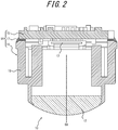
FIG. 2 is a cross-sectional diagram, taken along an optical axis, to illustrate the schematic configuration of the imaging apparatus ofFIG. 1 ; -
FIG. 3 is an enlarged cross-sectional diagram illustrating the bonded structure ofFIG. 2 without an adhesive body; -
FIG. 4 is an enlarged cross-sectional diagram illustrating a first modification to the support ofFIG. 3 ; -
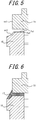
FIG. 5 is an enlarged cross-sectional diagram illustrating a second modification to the support ofFIG. 3 ; -
FIG. 6 is an enlarged cross-sectional diagram illustrating the configuration of the bonded structure ofFIG. 2 ; -
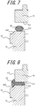
FIG. 7 illustrates a first step of a method of producing the bonded structure ofFIG. 2 ; -
FIG. 8 illustrates a second step of a method of producing the bonded structure ofFIG. 2 ; -
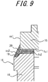
FIG. 9 illustrates a third step of a method of producing the bonded structure ofFIG. 2 ; -
FIG. 10 is an enlarged cross-sectional diagram illustrating the configuration of a bonded structure in a first example in which the adhesive body is sandwiched only between flat surfaces of plate-shaped members; and -
FIG. 11 is an enlarged cross-sectional diagram illustrating the configuration of a bonded structure in a second example in which the adhesive body is sandwiched only between flat surfaces of plate-shaped members. - An embodiment of a fixed structure to which the present disclosure is applied is described below with reference to the drawings.
- The bonded structure according to an embodiment of the present disclosure is, for example, applied to an imaging apparatus. An
imaging apparatus 10 to which the bonded structure according to the present embodiment is applied is, for example, mounted in amoveable body 11, as illustrated inFIG. 1 . - The
moveable body 11 may, for example, encompass vehicles, ships, and aircraft. Vehicles may, for example, include automobiles, industrial vehicles, railway vehicles, vehicles for daily life, and fixed-wing aircraft that run on a runway. Automobiles may, for example, include passenger vehicles, trucks, buses, motorcycles, and trolley buses. Industrial vehicles may, for example, include industrial vehicles for agriculture and for construction. Industrial vehicles may, for example, include forklifts and golf carts. Industrial vehicles for agriculture may, for example, include tractors, cultivators, transplanters, binders, combines, and lawnmowers. Industrial vehicles for construction may, for example, include bulldozers, scrapers, backhoes, cranes, dump cars, and road rollers. Vehicles may include man-powered vehicles. The types of vehicles are not limited to the above examples. For example, automobiles may include industrial vehicles that can be driven on the road. The same vehicle may also be included in multiple categories. Ships may, for example, include marine jets, boats, and tankers. Aircraft may, for example, include fixed-wing aircraft and rotorcraft. - As illustrated in
FIG. 2 , theimaging apparatus 10 includes an imagingoptical system 12, animage sensor 13, and a bonded structure 14. - The imaging
optical system 12 includes at least one optical element, such as a lens. The imagingoptical system 12 is designed and formed so that optical properties such as angle of view and depth of field become desired values. The imagingoptical system 12 is held by asecond member 16, which forms part of the below-described bonded structure 14, so that a subject image is formed on theimage sensor 13. - The
image sensor 13 is, for example, a charge coupled device (CCD) image sensor or a complementary metal oxide semiconductor (CMOS) image sensor. Theimage sensor 13 is mounted on afirst member 15, which forms part of the below-described bonded structure 14. Theimage sensor 13 captures the subject image formed by the imagingoptical system 12. - The bonded structure 14 includes the
first member 15, thesecond member 16, and anadhesive body 17. - As described above, the
first member 15 is a circuit board, for example, on which theimage sensor 13 is mounted. Thefirst member 15 may include a flat surface fs1, as illustrated inFIG. 3 . Thefirst member 15 supports theimage sensor 13 so that an optical detection surface of theimage sensor 13 is parallel to the flat surface fs1. A side surface ss1 of thefirst member 15 may be perpendicular or inclined relative to the flat surface fs1. - As viewed from a direction perpendicular to the flat surface fs1 of the
first member 15, the side surface ss1 of thefirst member 15 in the bonded structure 14 may be positioned inward from the edge of theadhesive body 17 on thesupport 18 side of thesecond member 16, described below. Furthermore, as viewed from the perpendicular direction, the side surface ss1 of thefirst member 15 in the bonded structure 14 may be positioned inward from a side surface ss2 of thesupport 18, described below. Inward from the side surface ss2 refers to being on the inside of the boundary line between the side surface ss2 and a facing surface fs2 of thesupport 18, or being on the facing surface fs2 side of the boundary line. - As illustrated in
FIG. 2 , thesecond member 16 is a lens case holding the imagingoptical system 12, for example, as described above. Thesecond member 16 may, for example, be formed by molding a resin. Thesecond member 16 may be cylindrical overall, for example, and may hold the imagingoptical system 12 so that the optical axis OA of the imagingoptical system 12 and the shaft core overlap. - The
second member 16 includes thesupport 18. Thesupport 18 is, for example, formed around the shaft core. As illustrated inFIG. 3 , thesupport 18 includes the facing surface fs2 and the side surface ss2. - The facing surface fs2 may include a flat surface perpendicular to the optical axis OA. The entire facing surface fs2 is perpendicular to the optical axis OA in the present embodiment. The facing surface fs2 faces the
first member 15 in the bonded structure 14. Specifically, the facing surface fs2 may face the flat surface fs1 of thefirst member 15. The facing surface fs2 may be parallel to the flat surface fs1 of thefirst member 15. - The side surface ss2 of the
support 18 is inclined relative to the facing surface fs2 so as to spread outward as viewed from the direction perpendicular to the facing surface fs2. The side surface ss2 may be a flat surface, as illustrated inFIG. 3 . When the side surface ss2 is configured to be a flat surface, the angle formed between the facing surface fs2 and the side surface ss2 may be greater than 90 degrees and less than 170 degrees. The side surface ss2 may be a curved surface protruding outward, as illustrated inFIG. 4 . The side surface ss2 may be a curved surface recessed inward, as illustrated inFIG. 5 . - The side surface ss2 may connect farther outward to a
liquid retainer 19 when viewed in a direction perpendicular to the facing surface fs2, as illustrated inFIG. 3 . Theliquid retainer 19 is, for example, at an angle of less than 180 degrees relative to the side surface ss2 and may be curved. - The
adhesive body 17 is positioned between thefirst member 15 and thesupport 18 and fixes thefirst member 15 to thesecond member 16, as illustrated inFIG. 6 . Theadhesive body 17 extends along thesupport 18 in close contact from the facing surface fs2 to the side surface ss2. Theadhesive body 17 has a fillet shape at an end thereof by the side surface ss2. The fillet shape is a shape that diverges in a direction perpendicular to the facing surface fs2 towards the end of theadhesive body 17 on the side surface ss2 side along a direction parallel to the facing surface fs2. - The
adhesive body 17 may extend from the portion of the flat surface fs1 of thefirst member 15 facing the facing surface fs2 to the side surface ss1 while in close contact. Theadhesive body 17 may have a fillet shape at the end thereof by the side surface ss1. - In greater detail, the
adhesive body 17 is cured adhesive. A photocurable resin or a thermosetting resin, for example, may be used as the adhesive. - Next, a method of producing the bonded structure 14 is described.
- The
second member 16 is allowed to stand with the facing surface fs2 facing vertically upward, for example, as illustrated inFIG. 7 . Thesecond member 16 may be allowed to stand with the facing surface fs2 facing vertically downward or in any other direction.Adhesive 20 is applied near the end of the facing surface fs2 by the side surface ss2. Thefirst member 15 is aligned relative to thesecond member 16 along the flat surface fs1 with the flat surface fs1 facing the facing surface fs2 above thesecond member 16. - The
first member 15 is displaced vertically downward, as illustrated inFIG. 8 . The adhesive 20 is compressed between the flat surface fs1 of thefirst member 15 and the facing surface fs2 of thesupport 18 by the displacement of thefirst member 15. By being compressed, the adhesive 20 extends towards the side surface ss1 of thefirst member 15 and the side surface ss2 of thesupport 18 and bulges out from the flat surface fs1 of thefirst member 15 and the facing surface fs2 of thesupport 18. - The bulging portion of the adhesive 20 extends by spreading out at the
support 18 side along the inclined side surface ss2 of thesupport 18 and further along the surface of theliquid retainer 19, as illustrated inFIG. 9 . The outer surface of the bulging portion of the adhesive 20 approaches a flat surface due to surface tension that narrows the outer surface in the space defined by the side surface ss1 of thefirst member 15, the side surface ss2 of thesupport 18, and the surface of theliquid retainer 19. Consequently, the adhesive 20 adopts a fillet shape at the side surface ss2 side of thesupport 18. The adhesive 20 also adopts a fillet shape at the side surface ss1 side of thefirst member 15. By being cured in this state, the adhesive 20 turns into theadhesive body 17, yielding the bonded structure 14. - In the bonded structure 14 of the present embodiment with the above configuration, the
adhesive body 17 extends from the facing surface fs2 of thesupport 18 to the side surface ss2 and has a fillet shape at the end thereof by the side surface ss2. As illustrated inFIGS. 10 and 11 , an adhesive body 17' that is sandwiched only between two members 15', 16' and is cured has a barrel or a bobbin shape. Stress therefore concentrates in a portion of the adhesive body 17', which may lead to cracking or detachment of the adhesive body 17'. In the bonded structure 14 with the above configuration, on the other hand, theadhesive body 17 has a fillet shape at thesupport 18 side. This relieves the concentration of stress inside theadhesive body 17 and can improve the fracture strength. - In the bonded structure 14 of the present embodiment, the
adhesive body 17 extends from the flat surface fs1 of thefirst member 15 to the side surface ss1 and has a fillet shape at the end thereof by the side surface ss1. This configuration can improve the fracture strength of the bonded structure 14 at thefirst member 15 side as well. - As viewed from a direction perpendicular to the flat surface fs1 of the
first member 15, the side surface ss1 of thefirst member 15 in the bonded structure 14 of the present embodiment is positioned inward from the side surface ss2 of thesupport 18. This configuration increases the size of the space that houses the portion of the adhesive 20 bulging towards the side surface ss1 of thefirst member 15 and the side surface ss2 of thesupport 18 during production of the bonded structure 14. The upper limit on the amount of the bulging portion that can form the fillet shape is thereby increased. Accordingly, the amount of adhesive 20 applied to form the fillet shape can be adjusted easily, and the fillet shape can be formed easily in theadhesive body 17 of the bonded structure 14. - Although the matter of the present disclosure has been explained with reference to the accompanying drawings and examples, it is to be noted that various changes and modifications will be apparent to those of ordinary skill in the art based on the present disclosure. Therefore, such changes and modifications are to be understood as included within the scope of the disclosure.
-
- 10
- Imaging apparatus
- 11
- Moveable body
- 12
- Imaging optical system
- 13
- Image sensor
- 14
- Bonded structure
- 15
- First member
- 15'
- Member
- 16
- Second member
- 16'
- Member
- 17, 17'
- Adhesive body
- 18
- Support
- 19
- Liquid retainer
- 20
- Adhesive
- fs1
- Flat surface of first member
- fs2
- Facing surface of support
- OA
- Optical axis
- ss1
- Side surface of first member
- ss2
- Side surface of support
Claims (5)
- A bonded structure comprising:a first member;a second member comprising a support, the support including a facing surface facing the first member and a side surface inclined outward as viewed from the first member; andan adhesive body positioned between the first member and the support, extending from the facing surface to the side surface, having a fillet shape at an end of the adhesive body by the side surface, and fixing the first member to the second member.
- The bonded structure of claim 1, wherein the adhesive body extends from a flat surface of the first member facing the facing surface to a side surface of the first member and has a fillet shape at an end of the adhesive body by the side surface of the first member.
- The bonded structure of claim 2, wherein the side surface of the first member is positioned inward from the side surface of the support when viewed from a direction perpendicular to the flat surface of the first member.
- An imaging apparatus comprising:the bonded structure of any one of claims 1 to 3;an image sensor mounted on the first member; andan imaging optical system comprising at least one optical element and held by the second member so that an image is formed on an optical detection surface of the image sensor.
- A moveable body comprising the imaging apparatus of claim 4.
Applications Claiming Priority (2)
| Application Number | Priority Date | Filing Date | Title |
|---|---|---|---|
| JP2018122336A JP6905958B2 (en) | 2018-06-27 | 2018-06-27 | Adhesive structures, imaging devices, and moving objects |
| PCT/JP2019/020746 WO2020003838A1 (en) | 2018-06-27 | 2019-05-24 | Bonded structure, imaging device, and moving body |
Publications (3)
| Publication Number | Publication Date |
|---|---|
| EP3817356A1 true EP3817356A1 (en) | 2021-05-05 |
| EP3817356A4 EP3817356A4 (en) | 2022-02-23 |
| EP3817356B1 EP3817356B1 (en) | 2024-07-10 |
Family
ID=68986388
Family Applications (1)
| Application Number | Title | Priority Date | Filing Date |
|---|---|---|---|
| EP19825661.2A Active EP3817356B1 (en) | 2018-06-27 | 2019-05-24 | Bonded structure, imaging device, and moving body |
Country Status (5)
| Country | Link |
|---|---|
| US (1) | US11597331B2 (en) |
| EP (1) | EP3817356B1 (en) |
| JP (1) | JP6905958B2 (en) |
| CN (1) | CN112236994B (en) |
| WO (1) | WO2020003838A1 (en) |
Families Citing this family (1)
| Publication number | Priority date | Publication date | Assignee | Title |
|---|---|---|---|---|
| KR20230020242A (en) * | 2021-08-03 | 2023-02-10 | 엘지이노텍 주식회사 | Camera module |
Family Cites Families (13)
| Publication number | Priority date | Publication date | Assignee | Title |
|---|---|---|---|---|
| US6930397B2 (en) * | 2001-03-28 | 2005-08-16 | International Rectifier Corporation | Surface mounted package with die bottom spaced from support board |
| JP2006332814A (en) * | 2005-05-24 | 2006-12-07 | Smk Corp | The camera module |
| JP2007019117A (en) | 2005-07-06 | 2007-01-25 | Matsushita Electric Ind Co Ltd | Optical device and manufacturing method thereof |
| JP4538416B2 (en) * | 2006-02-03 | 2010-09-08 | 株式会社日立メディアエレクトロニクス | Optical pickup device, manufacturing method thereof, and optical drive device |
| CN101578695B (en) * | 2006-12-26 | 2012-06-13 | 松下电器产业株式会社 | Semiconductor element mounting structure and semiconductor element mounting method |
| JP4967092B2 (en) * | 2008-02-26 | 2012-07-04 | 日本電産サンキョー株式会社 | Lens drive device |
| US8605211B2 (en) * | 2011-04-28 | 2013-12-10 | Apple Inc. | Low rise camera module |
| JP5756139B2 (en) | 2013-03-25 | 2015-07-29 | 日本電産コパル株式会社 | Imaging device |
| KR102193766B1 (en) | 2013-09-13 | 2020-12-22 | 엘지이노텍 주식회사 | Camera module |
| EP2942937B1 (en) * | 2014-05-07 | 2019-07-31 | Veoneer Sweden AB | Camera module for a motor vehicle and method of mounting a camera module |
| CN108028231B (en) | 2015-11-19 | 2021-07-23 | 京瓷株式会社 | Electronic component mounting board and electronic device |
| JP2018078148A (en) * | 2016-11-07 | 2018-05-17 | 株式会社東芝 | Optical semiconductor module |
| JP6943574B2 (en) | 2017-02-01 | 2021-10-06 | 株式会社神戸製鋼所 | Articulated welding robot |
-
2018
- 2018-06-27 JP JP2018122336A patent/JP6905958B2/en active Active
-
2019
- 2019-05-24 WO PCT/JP2019/020746 patent/WO2020003838A1/en not_active Ceased
- 2019-05-24 EP EP19825661.2A patent/EP3817356B1/en active Active
- 2019-05-24 CN CN201980037820.9A patent/CN112236994B/en active Active
- 2019-05-24 US US16/973,187 patent/US11597331B2/en active Active
Also Published As
| Publication number | Publication date |
|---|---|
| CN112236994A (en) | 2021-01-15 |
| CN112236994B (en) | 2022-03-22 |
| US11597331B2 (en) | 2023-03-07 |
| JP6905958B2 (en) | 2021-07-21 |
| WO2020003838A1 (en) | 2020-01-02 |
| US20210261068A1 (en) | 2021-08-26 |
| JP2020005104A (en) | 2020-01-09 |
| EP3817356A4 (en) | 2022-02-23 |
| EP3817356B1 (en) | 2024-07-10 |
Similar Documents
| Publication | Publication Date | Title |
|---|---|---|
| JP6308147B2 (en) | In-vehicle sensor mounting structure | |
| EP2965949A1 (en) | Attachment structure for in-vehicle camera | |
| EP2468572A1 (en) | Motor vehicle with a camera and method for operating a camera system in a motor vehicle | |
| US20240114222A1 (en) | Electronic device, imaging apparatus, and mobile body | |
| WO2018168469A1 (en) | Vehicle inner-mirror-equipped laminated glass for vehicles | |
| EP4037301B1 (en) | Imaging device and mobile body | |
| EP3817356A1 (en) | Bonded structure, imaging device, and moving body | |
| WO2020217908A1 (en) | Electronic instrument, imaging device, and mobile body | |
| EP3461689B1 (en) | Camera device and method for mounting a camera device for a motor vehicle | |
| CN111133744B (en) | Imaging device, imaging device manufacturing method, and moving body | |
| EP4037302B1 (en) | Imaging device and moving body | |
| US20140252738A1 (en) | Drive Axle for an Industrial Truck | |
| JP6957235B2 (en) | Imaging device and moving object | |
| CN204408519U (en) | car camera | |
| US11543614B2 (en) | Imaging apparatus, mobile object, and manufacturing method | |
| EP3846435A1 (en) | Electronic apparatus, image capture device, and mobile body | |
| CN204264013U (en) | A kind of automatic control system of automobile steering indicating light | |
| WO2019004006A1 (en) | Imaging device, method for producing imaging device, and moving body | |
| WO2021235255A1 (en) | Image display module | |
| DE102020133884A1 (en) | Optical detection devices for detecting objects, covering device for at least partially covering at least one optical system of an optical detection device and housing of an optical detection device | |
| DE102014013222A1 (en) | Environment detection unit for a vehicle |
Legal Events
| Date | Code | Title | Description |
|---|---|---|---|
| STAA | Information on the status of an ep patent application or granted ep patent |
Free format text: STATUS: THE INTERNATIONAL PUBLICATION HAS BEEN MADE |
|
| PUAI | Public reference made under article 153(3) epc to a published international application that has entered the european phase |
Free format text: ORIGINAL CODE: 0009012 |
|
| STAA | Information on the status of an ep patent application or granted ep patent |
Free format text: STATUS: REQUEST FOR EXAMINATION WAS MADE |
|
| 17P | Request for examination filed |
Effective date: 20201203 |
|
| AK | Designated contracting states |
Kind code of ref document: A1 Designated state(s): AL AT BE BG CH CY CZ DE DK EE ES FI FR GB GR HR HU IE IS IT LI LT LU LV MC MK MT NL NO PL PT RO RS SE SI SK SM TR |
|
| DAV | Request for validation of the european patent (deleted) | ||
| DAX | Request for extension of the european patent (deleted) | ||
| A4 | Supplementary search report drawn up and despatched |
Effective date: 20220121 |
|
| RIC1 | Information provided on ipc code assigned before grant |
Ipc: G03B 17/02 20210101ALI20220117BHEP Ipc: G02B 7/02 20210101ALI20220117BHEP Ipc: B64D 47/08 20060101ALI20220117BHEP Ipc: H04N 5/225 20060101AFI20220117BHEP |
|
| P01 | Opt-out of the competence of the unified patent court (upc) registered |
Effective date: 20230505 |
|
| REG | Reference to a national code |
Ref country code: DE Ref legal event code: R079 Free format text: PREVIOUS MAIN CLASS: H04N0005225000 Ipc: B60R0011040000 Ref country code: DE Ref legal event code: R079 Ref document number: 602019055077 Country of ref document: DE Free format text: PREVIOUS MAIN CLASS: H04N0005225000 Ipc: B60R0011040000 |
|
| GRAP | Despatch of communication of intention to grant a patent |
Free format text: ORIGINAL CODE: EPIDOSNIGR1 |
|
| STAA | Information on the status of an ep patent application or granted ep patent |
Free format text: STATUS: GRANT OF PATENT IS INTENDED |
|
| RIC1 | Information provided on ipc code assigned before grant |
Ipc: G03B 17/02 20210101ALI20240108BHEP Ipc: G02B 7/02 20210101ALI20240108BHEP Ipc: B64D 47/08 20060101ALI20240108BHEP Ipc: H04N 23/55 20230101ALI20240108BHEP Ipc: H04N 23/54 20230101ALI20240108BHEP Ipc: G03B 30/00 20210101ALI20240108BHEP Ipc: G03B 17/12 20210101ALI20240108BHEP Ipc: B60R 11/00 20060101ALI20240108BHEP Ipc: B60R 11/04 20060101AFI20240108BHEP |
|
| INTG | Intention to grant announced |
Effective date: 20240206 |
|
| GRAS | Grant fee paid |
Free format text: ORIGINAL CODE: EPIDOSNIGR3 |
|
| GRAA | (expected) grant |
Free format text: ORIGINAL CODE: 0009210 |
|
| STAA | Information on the status of an ep patent application or granted ep patent |
Free format text: STATUS: THE PATENT HAS BEEN GRANTED |
|
| AK | Designated contracting states |
Kind code of ref document: B1 Designated state(s): AL AT BE BG CH CY CZ DE DK EE ES FI FR GB GR HR HU IE IS IT LI LT LU LV MC MK MT NL NO PL PT RO RS SE SI SK SM TR |
|
| REG | Reference to a national code |
Ref country code: CH Ref legal event code: EP |
|
| REG | Reference to a national code |
Ref country code: DE Ref legal event code: R096 Ref document number: 602019055077 Country of ref document: DE |
|
| REG | Reference to a national code |
Ref country code: LT Ref legal event code: MG9D |
|
| REG | Reference to a national code |
Ref country code: NL Ref legal event code: MP Effective date: 20240710 |
|
| PG25 | Lapsed in a contracting state [announced via postgrant information from national office to epo] |
Ref country code: PT Free format text: LAPSE BECAUSE OF FAILURE TO SUBMIT A TRANSLATION OF THE DESCRIPTION OR TO PAY THE FEE WITHIN THE PRESCRIBED TIME-LIMIT Effective date: 20241111 |
|
| REG | Reference to a national code |
Ref country code: AT Ref legal event code: MK05 Ref document number: 1701790 Country of ref document: AT Kind code of ref document: T Effective date: 20240710 |
|
| PG25 | Lapsed in a contracting state [announced via postgrant information from national office to epo] |
Ref country code: NL Free format text: LAPSE BECAUSE OF FAILURE TO SUBMIT A TRANSLATION OF THE DESCRIPTION OR TO PAY THE FEE WITHIN THE PRESCRIBED TIME-LIMIT Effective date: 20240710 |
|
| PG25 | Lapsed in a contracting state [announced via postgrant information from national office to epo] |
Ref country code: PT Free format text: LAPSE BECAUSE OF FAILURE TO SUBMIT A TRANSLATION OF THE DESCRIPTION OR TO PAY THE FEE WITHIN THE PRESCRIBED TIME-LIMIT Effective date: 20241111 Ref country code: NL Free format text: LAPSE BECAUSE OF FAILURE TO SUBMIT A TRANSLATION OF THE DESCRIPTION OR TO PAY THE FEE WITHIN THE PRESCRIBED TIME-LIMIT Effective date: 20240710 |
|
| PG25 | Lapsed in a contracting state [announced via postgrant information from national office to epo] |
Ref country code: NO Free format text: LAPSE BECAUSE OF FAILURE TO SUBMIT A TRANSLATION OF THE DESCRIPTION OR TO PAY THE FEE WITHIN THE PRESCRIBED TIME-LIMIT Effective date: 20241010 |
|
| PG25 | Lapsed in a contracting state [announced via postgrant information from national office to epo] |
Ref country code: GR Free format text: LAPSE BECAUSE OF FAILURE TO SUBMIT A TRANSLATION OF THE DESCRIPTION OR TO PAY THE FEE WITHIN THE PRESCRIBED TIME-LIMIT Effective date: 20241011 Ref country code: FI Free format text: LAPSE BECAUSE OF FAILURE TO SUBMIT A TRANSLATION OF THE DESCRIPTION OR TO PAY THE FEE WITHIN THE PRESCRIBED TIME-LIMIT Effective date: 20240710 Ref country code: PL Free format text: LAPSE BECAUSE OF FAILURE TO SUBMIT A TRANSLATION OF THE DESCRIPTION OR TO PAY THE FEE WITHIN THE PRESCRIBED TIME-LIMIT Effective date: 20240710 |
|
| PG25 | Lapsed in a contracting state [announced via postgrant information from national office to epo] |
Ref country code: BG Free format text: LAPSE BECAUSE OF FAILURE TO SUBMIT A TRANSLATION OF THE DESCRIPTION OR TO PAY THE FEE WITHIN THE PRESCRIBED TIME-LIMIT Effective date: 20240710 |
|
| PG25 | Lapsed in a contracting state [announced via postgrant information from national office to epo] |
Ref country code: LV Free format text: LAPSE BECAUSE OF FAILURE TO SUBMIT A TRANSLATION OF THE DESCRIPTION OR TO PAY THE FEE WITHIN THE PRESCRIBED TIME-LIMIT Effective date: 20240710 |
|
| PG25 | Lapsed in a contracting state [announced via postgrant information from national office to epo] |
Ref country code: AT Free format text: LAPSE BECAUSE OF FAILURE TO SUBMIT A TRANSLATION OF THE DESCRIPTION OR TO PAY THE FEE WITHIN THE PRESCRIBED TIME-LIMIT Effective date: 20240710 Ref country code: IS Free format text: LAPSE BECAUSE OF FAILURE TO SUBMIT A TRANSLATION OF THE DESCRIPTION OR TO PAY THE FEE WITHIN THE PRESCRIBED TIME-LIMIT Effective date: 20241110 |
|
| PG25 | Lapsed in a contracting state [announced via postgrant information from national office to epo] |
Ref country code: HR Free format text: LAPSE BECAUSE OF FAILURE TO SUBMIT A TRANSLATION OF THE DESCRIPTION OR TO PAY THE FEE WITHIN THE PRESCRIBED TIME-LIMIT Effective date: 20240710 |
|
| PG25 | Lapsed in a contracting state [announced via postgrant information from national office to epo] |
Ref country code: ES Free format text: LAPSE BECAUSE OF FAILURE TO SUBMIT A TRANSLATION OF THE DESCRIPTION OR TO PAY THE FEE WITHIN THE PRESCRIBED TIME-LIMIT Effective date: 20240710 Ref country code: RS Free format text: LAPSE BECAUSE OF FAILURE TO SUBMIT A TRANSLATION OF THE DESCRIPTION OR TO PAY THE FEE WITHIN THE PRESCRIBED TIME-LIMIT Effective date: 20241010 |
|
| PG25 | Lapsed in a contracting state [announced via postgrant information from national office to epo] |
Ref country code: RS Free format text: LAPSE BECAUSE OF FAILURE TO SUBMIT A TRANSLATION OF THE DESCRIPTION OR TO PAY THE FEE WITHIN THE PRESCRIBED TIME-LIMIT Effective date: 20241010 Ref country code: PL Free format text: LAPSE BECAUSE OF FAILURE TO SUBMIT A TRANSLATION OF THE DESCRIPTION OR TO PAY THE FEE WITHIN THE PRESCRIBED TIME-LIMIT Effective date: 20240710 Ref country code: NO Free format text: LAPSE BECAUSE OF FAILURE TO SUBMIT A TRANSLATION OF THE DESCRIPTION OR TO PAY THE FEE WITHIN THE PRESCRIBED TIME-LIMIT Effective date: 20241010 Ref country code: LV Free format text: LAPSE BECAUSE OF FAILURE TO SUBMIT A TRANSLATION OF THE DESCRIPTION OR TO PAY THE FEE WITHIN THE PRESCRIBED TIME-LIMIT Effective date: 20240710 Ref country code: IS Free format text: LAPSE BECAUSE OF FAILURE TO SUBMIT A TRANSLATION OF THE DESCRIPTION OR TO PAY THE FEE WITHIN THE PRESCRIBED TIME-LIMIT Effective date: 20241110 Ref country code: HR Free format text: LAPSE BECAUSE OF FAILURE TO SUBMIT A TRANSLATION OF THE DESCRIPTION OR TO PAY THE FEE WITHIN THE PRESCRIBED TIME-LIMIT Effective date: 20240710 Ref country code: GR Free format text: LAPSE BECAUSE OF FAILURE TO SUBMIT A TRANSLATION OF THE DESCRIPTION OR TO PAY THE FEE WITHIN THE PRESCRIBED TIME-LIMIT Effective date: 20241011 Ref country code: FI Free format text: LAPSE BECAUSE OF FAILURE TO SUBMIT A TRANSLATION OF THE DESCRIPTION OR TO PAY THE FEE WITHIN THE PRESCRIBED TIME-LIMIT Effective date: 20240710 Ref country code: ES Free format text: LAPSE BECAUSE OF FAILURE TO SUBMIT A TRANSLATION OF THE DESCRIPTION OR TO PAY THE FEE WITHIN THE PRESCRIBED TIME-LIMIT Effective date: 20240710 Ref country code: BG Free format text: LAPSE BECAUSE OF FAILURE TO SUBMIT A TRANSLATION OF THE DESCRIPTION OR TO PAY THE FEE WITHIN THE PRESCRIBED TIME-LIMIT Effective date: 20240710 Ref country code: AT Free format text: LAPSE BECAUSE OF FAILURE TO SUBMIT A TRANSLATION OF THE DESCRIPTION OR TO PAY THE FEE WITHIN THE PRESCRIBED TIME-LIMIT Effective date: 20240710 |
|
| REG | Reference to a national code |
Ref country code: DE Ref legal event code: R097 Ref document number: 602019055077 Country of ref document: DE |
|
| PG25 | Lapsed in a contracting state [announced via postgrant information from national office to epo] |
Ref country code: DK Free format text: LAPSE BECAUSE OF FAILURE TO SUBMIT A TRANSLATION OF THE DESCRIPTION OR TO PAY THE FEE WITHIN THE PRESCRIBED TIME-LIMIT Effective date: 20240710 Ref country code: RO Free format text: LAPSE BECAUSE OF FAILURE TO SUBMIT A TRANSLATION OF THE DESCRIPTION OR TO PAY THE FEE WITHIN THE PRESCRIBED TIME-LIMIT Effective date: 20240710 Ref country code: SM Free format text: LAPSE BECAUSE OF FAILURE TO SUBMIT A TRANSLATION OF THE DESCRIPTION OR TO PAY THE FEE WITHIN THE PRESCRIBED TIME-LIMIT Effective date: 20240710 |
|
| PG25 | Lapsed in a contracting state [announced via postgrant information from national office to epo] |
Ref country code: EE Free format text: LAPSE BECAUSE OF FAILURE TO SUBMIT A TRANSLATION OF THE DESCRIPTION OR TO PAY THE FEE WITHIN THE PRESCRIBED TIME-LIMIT Effective date: 20240710 |
|
| PG25 | Lapsed in a contracting state [announced via postgrant information from national office to epo] |
Ref country code: CZ Free format text: LAPSE BECAUSE OF FAILURE TO SUBMIT A TRANSLATION OF THE DESCRIPTION OR TO PAY THE FEE WITHIN THE PRESCRIBED TIME-LIMIT Effective date: 20240710 |
|
| PG25 | Lapsed in a contracting state [announced via postgrant information from national office to epo] |
Ref country code: SK Free format text: LAPSE BECAUSE OF FAILURE TO SUBMIT A TRANSLATION OF THE DESCRIPTION OR TO PAY THE FEE WITHIN THE PRESCRIBED TIME-LIMIT Effective date: 20240710 Ref country code: IT Free format text: LAPSE BECAUSE OF FAILURE TO SUBMIT A TRANSLATION OF THE DESCRIPTION OR TO PAY THE FEE WITHIN THE PRESCRIBED TIME-LIMIT Effective date: 20240710 |
|
| PLBE | No opposition filed within time limit |
Free format text: ORIGINAL CODE: 0009261 |
|
| STAA | Information on the status of an ep patent application or granted ep patent |
Free format text: STATUS: NO OPPOSITION FILED WITHIN TIME LIMIT |
|
| 26N | No opposition filed |
Effective date: 20250411 |
|
| PGFP | Annual fee paid to national office [announced via postgrant information from national office to epo] |
Ref country code: DE Payment date: 20250402 Year of fee payment: 7 |
|
| PGFP | Annual fee paid to national office [announced via postgrant information from national office to epo] |
Ref country code: FR Payment date: 20250401 Year of fee payment: 7 |
|
| PG25 | Lapsed in a contracting state [announced via postgrant information from national office to epo] |
Ref country code: SE Free format text: LAPSE BECAUSE OF FAILURE TO SUBMIT A TRANSLATION OF THE DESCRIPTION OR TO PAY THE FEE WITHIN THE PRESCRIBED TIME-LIMIT Effective date: 20240710 |
|
| REG | Reference to a national code |
Ref country code: CH Ref legal event code: H13 Free format text: ST27 STATUS EVENT CODE: U-0-0-H10-H13 (AS PROVIDED BY THE NATIONAL OFFICE) Effective date: 20251223 |
|
| PG25 | Lapsed in a contracting state [announced via postgrant information from national office to epo] |
Ref country code: LU Free format text: LAPSE BECAUSE OF NON-PAYMENT OF DUE FEES Effective date: 20250524 |
|
| PG25 | Lapsed in a contracting state [announced via postgrant information from national office to epo] |
Ref country code: CH Free format text: LAPSE BECAUSE OF NON-PAYMENT OF DUE FEES Effective date: 20250531 |
|
| REG | Reference to a national code |
Ref country code: BE Ref legal event code: MM Effective date: 20250531 |
|
| PG25 | Lapsed in a contracting state [announced via postgrant information from national office to epo] |
Ref country code: MC Free format text: LAPSE BECAUSE OF FAILURE TO SUBMIT A TRANSLATION OF THE DESCRIPTION OR TO PAY THE FEE WITHIN THE PRESCRIBED TIME-LIMIT Effective date: 20240710 |
|
| PGFP | Annual fee paid to national office [announced via postgrant information from national office to epo] |
Ref country code: GB Payment date: 20260323 Year of fee payment: 8 |
|
| PG25 | Lapsed in a contracting state [announced via postgrant information from national office to epo] |
Ref country code: IE Free format text: LAPSE BECAUSE OF NON-PAYMENT OF DUE FEES Effective date: 20250524 |
|
| PG25 | Lapsed in a contracting state [announced via postgrant information from national office to epo] |
Ref country code: BE Free format text: LAPSE BECAUSE OF NON-PAYMENT OF DUE FEES Effective date: 20250531 |