EP3817089B1 - Battery module - Google Patents
Battery module Download PDFInfo
- Publication number
- EP3817089B1 EP3817089B1 EP19893165.1A EP19893165A EP3817089B1 EP 3817089 B1 EP3817089 B1 EP 3817089B1 EP 19893165 A EP19893165 A EP 19893165A EP 3817089 B1 EP3817089 B1 EP 3817089B1
- Authority
- EP
- European Patent Office
- Prior art keywords
- coupling
- hinge pin
- hinge
- bus
- coupling groove
- Prior art date
- Legal status (The legal status is an assumption and is not a legal conclusion. Google has not performed a legal analysis and makes no representation as to the accuracy of the status listed.)
- Active
Links
Images


Classifications
-
- H—ELECTRICITY
- H01—ELECTRIC ELEMENTS
- H01M—PROCESSES OR MEANS, e.g. BATTERIES, FOR THE DIRECT CONVERSION OF CHEMICAL ENERGY INTO ELECTRICAL ENERGY
- H01M50/00—Constructional details or processes of manufacture of the non-active parts of electrochemical cells other than fuel cells, e.g. hybrid cells
- H01M50/20—Mountings; Secondary casings or frames; Racks, modules or packs; Suspension devices; Shock absorbers; Transport or carrying devices; Holders
- H01M50/204—Racks, modules or packs for multiple batteries or multiple cells
-
- H—ELECTRICITY
- H01—ELECTRIC ELEMENTS
- H01M—PROCESSES OR MEANS, e.g. BATTERIES, FOR THE DIRECT CONVERSION OF CHEMICAL ENERGY INTO ELECTRICAL ENERGY
- H01M50/00—Constructional details or processes of manufacture of the non-active parts of electrochemical cells other than fuel cells, e.g. hybrid cells
- H01M50/20—Mountings; Secondary casings or frames; Racks, modules or packs; Suspension devices; Shock absorbers; Transport or carrying devices; Holders
-
- H—ELECTRICITY
- H01—ELECTRIC ELEMENTS
- H01M—PROCESSES OR MEANS, e.g. BATTERIES, FOR THE DIRECT CONVERSION OF CHEMICAL ENERGY INTO ELECTRICAL ENERGY
- H01M10/00—Secondary cells; Manufacture thereof
- H01M10/42—Methods or arrangements for servicing or maintenance of secondary cells or secondary half-cells
- H01M10/425—Structural combination with electronic components, e.g. electronic circuits integrated to the outside of the casing
-
- H—ELECTRICITY
- H01—ELECTRIC ELEMENTS
- H01M—PROCESSES OR MEANS, e.g. BATTERIES, FOR THE DIRECT CONVERSION OF CHEMICAL ENERGY INTO ELECTRICAL ENERGY
- H01M50/00—Constructional details or processes of manufacture of the non-active parts of electrochemical cells other than fuel cells, e.g. hybrid cells
- H01M50/20—Mountings; Secondary casings or frames; Racks, modules or packs; Suspension devices; Shock absorbers; Transport or carrying devices; Holders
- H01M50/204—Racks, modules or packs for multiple batteries or multiple cells
- H01M50/207—Racks, modules or packs for multiple batteries or multiple cells characterised by their shape
- H01M50/209—Racks, modules or packs for multiple batteries or multiple cells characterised by their shape adapted for prismatic or rectangular cells
-
- H—ELECTRICITY
- H01—ELECTRIC ELEMENTS
- H01M—PROCESSES OR MEANS, e.g. BATTERIES, FOR THE DIRECT CONVERSION OF CHEMICAL ENERGY INTO ELECTRICAL ENERGY
- H01M50/00—Constructional details or processes of manufacture of the non-active parts of electrochemical cells other than fuel cells, e.g. hybrid cells
- H01M50/20—Mountings; Secondary casings or frames; Racks, modules or packs; Suspension devices; Shock absorbers; Transport or carrying devices; Holders
- H01M50/204—Racks, modules or packs for multiple batteries or multiple cells
- H01M50/207—Racks, modules or packs for multiple batteries or multiple cells characterised by their shape
- H01M50/211—Racks, modules or packs for multiple batteries or multiple cells characterised by their shape adapted for pouch cells
-
- H—ELECTRICITY
- H01—ELECTRIC ELEMENTS
- H01M—PROCESSES OR MEANS, e.g. BATTERIES, FOR THE DIRECT CONVERSION OF CHEMICAL ENERGY INTO ELECTRICAL ENERGY
- H01M50/00—Constructional details or processes of manufacture of the non-active parts of electrochemical cells other than fuel cells, e.g. hybrid cells
- H01M50/20—Mountings; Secondary casings or frames; Racks, modules or packs; Suspension devices; Shock absorbers; Transport or carrying devices; Holders
- H01M50/244—Secondary casings; Racks; Suspension devices; Carrying devices; Holders characterised by their mounting method
-
- H—ELECTRICITY
- H01—ELECTRIC ELEMENTS
- H01M—PROCESSES OR MEANS, e.g. BATTERIES, FOR THE DIRECT CONVERSION OF CHEMICAL ENERGY INTO ELECTRICAL ENERGY
- H01M50/00—Constructional details or processes of manufacture of the non-active parts of electrochemical cells other than fuel cells, e.g. hybrid cells
- H01M50/20—Mountings; Secondary casings or frames; Racks, modules or packs; Suspension devices; Shock absorbers; Transport or carrying devices; Holders
- H01M50/249—Mountings; Secondary casings or frames; Racks, modules or packs; Suspension devices; Shock absorbers; Transport or carrying devices; Holders specially adapted for aircraft or vehicles, e.g. cars or trains
-
- H—ELECTRICITY
- H01—ELECTRIC ELEMENTS
- H01M—PROCESSES OR MEANS, e.g. BATTERIES, FOR THE DIRECT CONVERSION OF CHEMICAL ENERGY INTO ELECTRICAL ENERGY
- H01M50/00—Constructional details or processes of manufacture of the non-active parts of electrochemical cells other than fuel cells, e.g. hybrid cells
- H01M50/20—Mountings; Secondary casings or frames; Racks, modules or packs; Suspension devices; Shock absorbers; Transport or carrying devices; Holders
- H01M50/258—Modular batteries; Casings provided with means for assembling
-
- H—ELECTRICITY
- H01—ELECTRIC ELEMENTS
- H01M—PROCESSES OR MEANS, e.g. BATTERIES, FOR THE DIRECT CONVERSION OF CHEMICAL ENERGY INTO ELECTRICAL ENERGY
- H01M50/00—Constructional details or processes of manufacture of the non-active parts of electrochemical cells other than fuel cells, e.g. hybrid cells
- H01M50/20—Mountings; Secondary casings or frames; Racks, modules or packs; Suspension devices; Shock absorbers; Transport or carrying devices; Holders
- H01M50/262—Mountings; Secondary casings or frames; Racks, modules or packs; Suspension devices; Shock absorbers; Transport or carrying devices; Holders with fastening means, e.g. locks
- H01M50/264—Mountings; Secondary casings or frames; Racks, modules or packs; Suspension devices; Shock absorbers; Transport or carrying devices; Holders with fastening means, e.g. locks for cells or batteries, e.g. straps, tie rods or peripheral frames
-
- H—ELECTRICITY
- H01—ELECTRIC ELEMENTS
- H01M—PROCESSES OR MEANS, e.g. BATTERIES, FOR THE DIRECT CONVERSION OF CHEMICAL ENERGY INTO ELECTRICAL ENERGY
- H01M50/00—Constructional details or processes of manufacture of the non-active parts of electrochemical cells other than fuel cells, e.g. hybrid cells
- H01M50/20—Mountings; Secondary casings or frames; Racks, modules or packs; Suspension devices; Shock absorbers; Transport or carrying devices; Holders
- H01M50/284—Mountings; Secondary casings or frames; Racks, modules or packs; Suspension devices; Shock absorbers; Transport or carrying devices; Holders with incorporated circuit boards, e.g. printed circuit boards [PCB]
-
- H—ELECTRICITY
- H01—ELECTRIC ELEMENTS
- H01M—PROCESSES OR MEANS, e.g. BATTERIES, FOR THE DIRECT CONVERSION OF CHEMICAL ENERGY INTO ELECTRICAL ENERGY
- H01M50/00—Constructional details or processes of manufacture of the non-active parts of electrochemical cells other than fuel cells, e.g. hybrid cells
- H01M50/50—Current conducting connections for cells or batteries
- H01M50/502—Interconnectors for connecting terminals of adjacent batteries; Interconnectors for connecting cells outside a battery casing
- H01M50/503—Interconnectors for connecting terminals of adjacent batteries; Interconnectors for connecting cells outside a battery casing characterised by the shape of the interconnectors
-
- H—ELECTRICITY
- H01—ELECTRIC ELEMENTS
- H01M—PROCESSES OR MEANS, e.g. BATTERIES, FOR THE DIRECT CONVERSION OF CHEMICAL ENERGY INTO ELECTRICAL ENERGY
- H01M50/00—Constructional details or processes of manufacture of the non-active parts of electrochemical cells other than fuel cells, e.g. hybrid cells
- H01M50/50—Current conducting connections for cells or batteries
- H01M50/502—Interconnectors for connecting terminals of adjacent batteries; Interconnectors for connecting cells outside a battery casing
- H01M50/505—Interconnectors for connecting terminals of adjacent batteries; Interconnectors for connecting cells outside a battery casing comprising a single busbar
-
- H—ELECTRICITY
- H01—ELECTRIC ELEMENTS
- H01M—PROCESSES OR MEANS, e.g. BATTERIES, FOR THE DIRECT CONVERSION OF CHEMICAL ENERGY INTO ELECTRICAL ENERGY
- H01M50/00—Constructional details or processes of manufacture of the non-active parts of electrochemical cells other than fuel cells, e.g. hybrid cells
- H01M50/50—Current conducting connections for cells or batteries
- H01M50/502—Interconnectors for connecting terminals of adjacent batteries; Interconnectors for connecting cells outside a battery casing
- H01M50/507—Interconnectors for connecting terminals of adjacent batteries; Interconnectors for connecting cells outside a battery casing comprising an arrangement of two or more busbars within a container structure, e.g. busbar modules
-
- H—ELECTRICITY
- H01—ELECTRIC ELEMENTS
- H01M—PROCESSES OR MEANS, e.g. BATTERIES, FOR THE DIRECT CONVERSION OF CHEMICAL ENERGY INTO ELECTRICAL ENERGY
- H01M2220/00—Batteries for particular applications
- H01M2220/20—Batteries in motive systems, e.g. vehicle, ship, plane
-
- Y—GENERAL TAGGING OF NEW TECHNOLOGICAL DEVELOPMENTS; GENERAL TAGGING OF CROSS-SECTIONAL TECHNOLOGIES SPANNING OVER SEVERAL SECTIONS OF THE IPC; TECHNICAL SUBJECTS COVERED BY FORMER USPC CROSS-REFERENCE ART COLLECTIONS [XRACs] AND DIGESTS
- Y02—TECHNOLOGIES OR APPLICATIONS FOR MITIGATION OR ADAPTATION AGAINST CLIMATE CHANGE
- Y02E—REDUCTION OF GREENHOUSE GAS [GHG] EMISSIONS, RELATED TO ENERGY GENERATION, TRANSMISSION OR DISTRIBUTION
- Y02E60/00—Enabling technologies; Technologies with a potential or indirect contribution to GHG emissions mitigation
- Y02E60/10—Energy storage using batteries
Definitions
- the present invention relates to a battery module, and more particularly, it relates to a battery module including a bus-bar frame where a bus bar is installed, and an upper plate coupled with the bus-bar frame.
- KR 2018 0078777 discloses an example of battery module and US 5,992,681 discloses a door latch assembly, such as for a battery compartment housing.
- Rechargeable batteries having high application characteristics and electrical characteristics such as high energy density according to their products are widely applied to battery vehicles, hybrid vehicles, and electric power storage devices driven by electric driving sources as well as portable devices. These rechargeable batteries are attracting attention as new energy sources for improving environmentally-friendliness and energy efficiency in that they do not generate any by-products of energy use as well as their primary merit, which can drastically reduce the use of fossil fuels.
- the battery pack applied to the battery vehicle has a structure in which a plurality of cell assemblies including a plurality of unit cells are coupled in series to obtain high power.
- the unit cell can be repeatedly charged and discharged by electrochemical reaction between constituent elements, including positive and negative current collectors, separators, active materials, and electrolyte solutions.
- a battery module formed of at least one battery cell is formed first, and other constituent elements are added by using the at least one battery module, thereby forming a battery pack.
- the number of battery modules included in the battery pack or the number of battery cells included in the battery module may be variously set according to a required output voltage or charge and discharge capacity.
- the battery module set as stated above includes a bus bar assembly that electrically connects a plurality of battery cells and electrode leads of the plurality of battery cells.
- the bus bar assembly has a structure in which a bus bar and a bus-bar frame are coupled, and in this case, the bus-bar frame is assembled with an upper plate that covers the top surface of the battery cells.
- a part where the bus-bar frame and the upper plate are assembled may be separated during the process or during the movement of the module, and in this case, problems such as tearing of a flexible printed circuit board formed over the bus-bar frame and upper plate may occur.
- the bus-bar frame pivots more than necessary, causing damage to the internal cell assembly, and there is a need for a structure that can prevent such problems.
- the problem to be solved by the present invention is to provide a battery module that can prevent damage to devices due to separation of a bus-bar frame and an upper plate, and also enable easy assembling of the bus-bar frame and the upper plate.
- a battery module includes: a cell assembly that includes at least one battery cell; an upper plate that covers one side of the cell assembly, and includes a hinge pin at at least one corner thereof; and a bus-bar frame that covers the other side, which neighbors the side of the cell assembly, covered by the upper plate, and coupled to the upper plate by including a hinge coupling portion that is coupled with the hinge pin, wherein the hinge coupling portion comprises a hinge pin receiving portion where the hinge pin is received and a hinge pin cover portion that covers the hinge pin, and one of the hinge pin and the hinge coupling portion comprises a coupling protrusion portion, and the other comprises a coupling groove portion corresponding to the coupling protrusion portion.
- the hinge pin cover portion completely covers the hinge pin.
- the coupling groove portion includes a main coupling groove portion, and a preliminary coupling groove portion disposed at a distance from the main coupling groove portion.
- the hinge pin may include the coupling protrusion portion, and the hinge coupling portion may include the main coupling groove portion and the preliminary coupling groove portion.
- the hinge coupling portion may have a circular-shaped cross-section, and a distance between the main coupling groove portion and the preliminary coupling groove may be less than 1/4 of a circular arc of the circular-shaped cross-section.
- the bus-bar frame is pivotably coupled to the upper plate by the hinge coupling portion.
- Pivoting of the bus-bar frame may be limited by coupling between the coupling protrusion portion and the main coupling groove portion.
- the bus-bar frame may be perpendicularly coupled to the upper plate while the coupling protrusion portion and the main coupling groove portion are in a coupled state.
- the cell assembly may be mounted below the upper plate in a preliminary coupling state in which the coupling protrusion portion and the preliminary coupling groove portion are coupled, and the bus-bar frame may be assembled to cover one side of the cell assembly by pivoting of the bus-bar frame.
- the hinge pin receiving portion and the hinge pin cover portion are coupled by a snap fit structure.
- the battery module may further include a flexible printed circuit board formed on a top surface of the upper plate, wherein the flexible printed circuit board may be formed by extending from one side of the upper plate adjacent to the hinge coupling portion to one side of the bus-bar frame passing one side adjacent to the hinge coupling portion.
- the hinge coupling portion may include the coupling protrusion portion, and the hinge pin may include the main coupling groove portion and the preliminary coupling groove portion.
- the hinge coupling portion may have a circular-shaped cross-section, and a distance between the main coupling groove portion and the preliminary coupling groove may be less than 1/4 of a circular arc of the circular-shaped cross-section.
- a battery pack according to another exemplary embodiment of the present invention may include the least one battery module, and a pack case that packages the at least one battery module.
- a device may include the at least one battery pack.
- the flexible printed circuit board and the like can be prevented from being damaged due to separation of the bus-bar frame and the upper place because the hinge pin is completely covered, and precise assembly of the bus-bar frame and the upper plate can be easily carried out by coupling of the coupling protrusion portion and the coupling groove portion formed in the hinge coupling portion and the hinge pin.
- the phrase “on a plane” means viewing a target portion from the top
- the phrase “on a cross-section” means viewing a cross-section formed by vertically cutting a target portion from the side.
- FIG. 1 is a perspective view of a battery module according to an exemplary embodiment of the present invention.
- a battery module 10 includes a cell assembly 100, an upper plate 140 that covers the cell assembly 100, and a bus-bar frame 150 that is coupled to the upper plate 140 and covers at least one side of the cell assembly 100.
- the cell assembly 100 and the upper plate 140 are received in a module case (not shown), and the bus-bar frame 150 covers an opening of the module case.
- the cell assembly 100 is formed of a plurality of battery cells, and may be formed, for example, as a pouch-type rechargeable battery.
- the plurality of battery cells are stacked inside the cell assembly 100, and they may be electrically connected to each other.
- Each of the battery cells may include an electrode assembly, a battery case that receives the electrode assembly, and an electrode lead 105 (shown in FIG. 4 ) that protrudes outward from the battery case and is electrically connected with the electrode assembly.
- the electrode assembly may include a positive electrode plate, a negative electrode plate, and a separator, and may adopt an electrode assembly having a known structure, and therefore no further detailed description will be provided.
- the bus-bar frame 150 is disposed to cover the cell assembly 100, and a bus bar 130 may be fixed to the bus-bar frame 150.
- the bus-bar frame 150 includes a lead slot that is formed of an insulator and electrode leads 105 (shown in FIG. 4 ) drawn out from the cell assembly 100 can be passed therethrough, and the bus bar 130 may electrically connect the electrode leads 105 (shown in FIG. 4 ) of the cell assembly 100.
- bus-bar frame 150 Various other electrical parts may be attached to the bus-bar frame 150.
- an internal circuit board (ICB) and a battery management system (BMS) may be provided in the bus-bar frame 150, and the electric parts such as ICB and the BMS may be electrically connected with the plurality of battery cells.
- ICB internal circuit board
- BMS battery management system
- the upper plate 140 is disposed on an upper portion of the cell assembly 100, and the bus-bar frames 150 are pivotably provided at opposite sides thereof.
- the bus bar 130 is mounted to the bus-bar frame 150, and a flexible printed circuit board (FPCB) 145 may be disposed on an upper end along a length direction of the upper plate 140.
- FPCB flexible printed circuit board
- the flexible printed circuit board 145 is electrically connected with the bus bar 130, over-voltage and over-current of the battery cell can be sensed therethrough, and a connector 160 is connected to one end of the flexible printed circuit board 145 such that a signal related to voltage sensing and temperature sensing may be transmitted to or received from a controller provided outside the battery module 10.
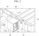
- FIG. 2 is an enlarged view of the part A in FIG. 1
- FIG. 3 is a cross-sectional view of FIG. 1 , taken along the line III-III' in FIG. 2 .
- the upper plate 140 and the bus-bar frame 150 are coupled by a hinge structure as shown in the part A.
- the upper plate 140 includes a hinge pin 141 in at least one corner thereof.
- the hinge pin 141 is coupled to a hinge coupling portion 151 of the bus-bar frame 150, and is disposed between a pair of hinge pin supporting portions 142 protruded in a direction that is parallel with the top surface of the upper plate 140 from the at least one corner of the upper plate 140.
- One or more hinge pins 141 and hinge pin supporting portions 142 may be provided, and preferably two or more may be provided on one corner of the upper plate 140.
- the bus-bar frame 150 includes the hinge coupling portion 151 that is coupled to the hinge pin 141.
- the hinge coupling portion 151 protrudes in a direction that is parallel with one side of the bus-bar frame 150 from a corner or the bus-bar frame 150, and as the hinge coupling portion 151 and the hinge pin 141 are coupled to each other, the upper plate 140 and the bus-bar frame 150 may be coupled while forming a right angle.
- the hinge coupling portion 151 includes a hinge pin receiving portion 152 where the hinge pin 141 is received, and a hinge pin cover portion 153 that covers the hinge pin 141.
- the hinge coupling portion 151 is formed on a corner of the hinge pin 141, and includes a cylindrical surface corresponding to the shape of the hinge pin 141 such that the hinge pin 141 may be received therein.
- the hinge pin cover portion 153 is formed to completely cover the hinge pin 141 placed on the hinge pin receiving portion 152, is pivotably formed at a portion that contacts the hinge pin receiving portion 152, and is coupled with the hinge pin receiving portion 152 through a snap fit structure at the opposite side. For example, as shown in FIG.
- a snap fit groove portion 152a is formed at an end of the hinge pin receiving portion 152 and a snap fit protrusion portion 153a is formed at an end of the hinge pin cover portion 153 such that the hinge pin 141 can be completely coupled by coupling of the snap fit groove portion 152a and the snap fit protrusion portion 153a.
- the present structure is not limited thereto, and positions of the snap fit groove portion and the groove portion may be changed as necessary. As shown in the drawing, only one end may be formed in a snap fit structure, or both ends may be formed in a snap fit structure..
- the bus-bar frame 150 can be prevented from being separated from the upper plate 140. That is, according to a conventional structure, the hinge pin 141 is exposed to an upper portion of a hinge coupling portion such that the battery module may move or the hinge pin may be separated from the hinge coupling portion in a subsequent process. In this case, the flexible printed circuit board 145 extended to the bus bar frame 150 from the top surface of the upper plate 140 may be torn or cut due to separation between the bus-bar frame 150 and the upper plate 140 caused by separation of the hinge pin.
- the hinge pin 141 is completely surrounded by the hinge coupling portion 151 such that the separation between the bus-bar frame 150 and the upper plate 140 can be prevented, and accordingly, damage to the flexible printed circuit board 145 can be prevented.
- the hinge coupling portion 151 includes an additional hinge pin cover portion 153 that covers the hinge pin 141 so that convenience in assembly can be maintained.
- FIG. 4 shows an assembled state of the battery module according to the exemplary embodiment of the present invention
- FIG. 5 is an enlarged view of an assembly process of the battery module according to the exemplary embodiment of the present invention.
- the hinge pin 141 includes a coupling protrusion portion 141a, and coupling groove portions 151a and 151b that correspond to the coupling protrusion portion 141a may be formed in one of the hinge pin receiving portion 152 and the hinge pin cover portion 153.
- the coupling groove portions 151a and 151b include a main coupling groove portion 151a and a preliminary coupling groove portion 151b that is disposed at a distance from the main coupling groove portion 151a.
- the coupling protrusion portion 141a of the hinge pin 141 and the main coupling groove portion 151a are coupled to each other in a state of being assembled while forming the right angle.
- pivoting of the bus-bar frame 150 is limited, and thus stability in assembly can be maintained, and when the upper plate 140 and the bus-bar frame 150 are assembled, even if a worker's skill level is low, the pivoting stops at the correct position, enabling precise assembly.
- the coupling protrusion portion 141a is coupled to the main coupling groove portion 151a such that the bus-bar frame 150 can be prevented from pivoting over a right angle, thereby preventing damage to the cell assembly 100.
- the bus-bar frame 150 is configured to be able to pivot around the hinge pin 141 while the hinge coupling portion 151 and the hinge pin 141 are coupled.
- the coupling protrusion portion 141a formed in the hinge pin 141 is mounted to be coupled with the preliminary coupling groove portion 151b formed in the hinge coupling portion 151, and then the snap fit protrusion portion 153a is coupled to the snap fit groove portion 152a such that the hinge pin 141 is covered by the hinge pin cover portion 153.
- a portion where the hinge pin receiving portion 152 and the hinge pin cover portion 153 contact each other may be formed to be foldable by reducing a thickness of plastic as shown in FIG. 5 , formed by introducing another hinge structure, or formed by introducing a snap fit structure.
- the bus-bar frame 150 pivots in the direction of the arrow.
- the coupling between the preliminary coupling groove portion 151b and the coupling protrusion portion 141a is released, and since the hinge coupling portion 151 is formed of a plastic injection-molded material, the inside of the hinge coupling portion 151 is forced to be slightly opened by an external force during the pivoting process such that the coupling protrusion portion 141a deviates from the preliminary coupling groove portion 151b and the coupling protrusion portion 141a can pivot (tightly fitted shape).
- the coupling protrusion portion 141a meets the main coupling groove portion 151a by pivoting, the coupling protrusion portion 141a is received inside the main coupling groove portion 151a.
- the pivoting of the bus-bar frame 150 is stopped, and the bus-bar frame 150 and the top plate 140 can be coupled while forming a right angle.
- a distance between the preliminary coupling groove portion 151b and the main coupling groove portion 151a may be adjusted such that the bus-bar frame 150 may pivot within 90 degrees until the bus-bar frame 150 is perpendicularly coupled with the upper plate 140 from a state of being initially assembled to the upper plate 140. That is, when the cross-section of the hinge coupling portion 151 has a circular shape, a separation distance between the main coupling groove portion 151a and the preliminary coupling groove portion 151b may be less than 1/4 of a circular arc of the circular-shaped cross-section. The distance can be adjusted depending on a work environment such as a working space, and a pivoting distance of the bus-bar frame 150 may be reduced as the distance is reduced.
- the flexible printed circuit board and the like can be prevented from being damaged due to separation between the bus-bar frame and the upper plate by the structure of completely covering the hinge pin, and precise assembly of the bus-bar frame and the upper plate can be easily carried out by the coupling of the hinge coupling portion, the coupling protrusion portion formed in the hinge pin, and the coupling groove portion.
- FIG. 6 illustrates features according to another exemplary embodiment of the present invention.
- a battery module according to another exemplary embodiment of the present invention is different from the battery module of the above-described exemplary embodiment in that a coupling protrusion portion 151c is formed in a hinge pin cover portion 153 of a bus-bar frame 150, and coupling groove portions 141b and 141c are formed in a hinge pin 141 of an upper plate 140.
- the present exemplary embodiment can be applicable to an assembly environment that is different from the assembly environment of the above-described exemplary embodiment.
- the coupling groove portions 141b and 141c of the hinge pin 141 also include a main coupling groove portion 141b and a preliminary coupling groove portion 141c, and a distance between the main coupling groove portion 141b and the preliminary coupling groove portion 141c may be adjusted such that the bus-bar frame 150 may pivot within 90 degrees until the bus-bar frame 150 is perpendicularly coupled with the upper plate 140 from a state of being initially assembled to the upper plate 140. That is, when the cross-section of the hinge pin 141 has a circular shape, a distance between the main coupling groove portion 141b and the preliminary coupling groove portion 141c may be less than 1/4 of a circular arc of the circular-shaped cross-section. The distance can be adjusted depending on a work environment such as a working space, and a pivoting distance of the bus-bar frame 150 may be reduced as the distance is reduced.
- positions of the coupling protrusion portion 151c and the coupling groove portions 141b and 141c may be appropriately selected depending on the assembly sequence or method, and the position is not particularly limited as long as the coupling protrusion portion 151c and the main coupling groove portion 141b are coupled at a position where the bus-bar frame 150 and the upper plate 140 are assembled at a right angle.
- one or more of the battery modules according to the exemplary embodiment of the present invention may be packaged in a pack case to form a battery pack.
- the battery module described above and the battery pack including the same can be applied to various devices.
- the device may be applied to a transportation means such as an electric bicycle, an electric vehicle, a hybrid vehicle, and the like, but the present invention is not limited thereto, and can be applied to various devices that can use a battery module and a battery pack including the same, and this also belongs to the scope of the present invention.
- battery module 100 cell assembly 105: electrode lead 130: bus bar 140: upper plate 141: hinge pin 142: hinge pin supporting portion 141a, 151c: protrusion portion 145: flexible printed circuit board 150: bus-bar frame 151: hinge coupling portion 151a, 141b: main coupling groove portion 151b, 141c: preliminary coupling groove portion 152: hinge pin receiving portion 153: hinge pin cover portion 152a: snap fit groove portion 153a: snap fit protrusion portion 160: connector
Landscapes
- Chemical & Material Sciences (AREA)
- Chemical Kinetics & Catalysis (AREA)
- Electrochemistry (AREA)
- General Chemical & Material Sciences (AREA)
- Engineering & Computer Science (AREA)
- Microelectronics & Electronic Packaging (AREA)
- Manufacturing & Machinery (AREA)
- Aviation & Aerospace Engineering (AREA)
- Connection Of Batteries Or Terminals (AREA)
- Battery Mounting, Suspending (AREA)
Description
- This application claims priority to and the benefit of
Korean Patent Application No. 10-2018-0156149 filed in the Korean Intellectual Property Office on December 06, 2018 - The present invention relates to a battery module, and more particularly, it relates to a battery module including a bus-bar frame where a bus bar is installed, and an upper plate coupled with the bus-bar frame.
-
KR 2018 0078777 US 5,992,681 discloses a door latch assembly, such as for a battery compartment housing. - Rechargeable batteries having high application characteristics and electrical characteristics such as high energy density according to their products are widely applied to battery vehicles, hybrid vehicles, and electric power storage devices driven by electric driving sources as well as portable devices. These rechargeable batteries are attracting attention as new energy sources for improving environmentally-friendliness and energy efficiency in that they do not generate any by-products of energy use as well as their primary merit, which can drastically reduce the use of fossil fuels.
- The battery pack applied to the battery vehicle has a structure in which a plurality of cell assemblies including a plurality of unit cells are coupled in series to obtain high power. The unit cell can be repeatedly charged and discharged by electrochemical reaction between constituent elements, including positive and negative current collectors, separators, active materials, and electrolyte solutions.
- Meanwhile, as the need for a large capacity structure increases, including the use of energy storage sources, a demand for battery packs having a multi-module structure in which a plurality of rechargeable batteries formed by assembling a plurality of battery modules coupled in series and/or in parallel with each other has increased.
- In general, when a battery pack is formed by coupling a plurality of battery cells in series/in parallel, a battery module formed of at least one battery cell is formed first, and other constituent elements are added by using the at least one battery module, thereby forming a battery pack. The number of battery modules included in the battery pack or the number of battery cells included in the battery module may be variously set according to a required output voltage or charge and discharge capacity. The battery module set as stated above includes a bus bar assembly that electrically connects a plurality of battery cells and electrode leads of the plurality of battery cells.
- Conventionally, the bus bar assembly has a structure in which a bus bar and a bus-bar frame are coupled, and in this case, the bus-bar frame is assembled with an upper plate that covers the top surface of the battery cells. However, a part where the bus-bar frame and the upper plate are assembled may be separated during the process or during the movement of the module, and in this case, problems such as tearing of a flexible printed circuit board formed over the bus-bar frame and upper plate may occur. In addition, during the assembly process of the bus-bar frame and upper plate, the bus-bar frame pivots more than necessary, causing damage to the internal cell assembly, and there is a need for a structure that can prevent such problems.
- The invention is defined in the appended claims.
- The problem to be solved by the present invention is to provide a battery module that can prevent damage to devices due to separation of a bus-bar frame and an upper plate, and also enable easy assembling of the bus-bar frame and the upper plate.
- However, the problems to be solved by the exemplary embodiments of the present invention are not limited to the above-described problems, and can be variously extended in a range of technical ideas included in the present invention.
- A battery module according to an exemplary embodiment of the present invention includes: a cell assembly that includes at least one battery cell; an upper plate that covers one side of the cell assembly, and includes a hinge pin at at least one corner thereof; and a bus-bar frame that covers the other side, which neighbors the side of the cell assembly, covered by the upper plate, and coupled to the upper plate by including a hinge coupling portion that is coupled with the hinge pin, wherein the hinge coupling portion comprises a hinge pin receiving portion where the hinge pin is received and a hinge pin cover portion that covers the hinge pin, and one of the hinge pin and the hinge coupling portion comprises a coupling protrusion portion, and the other comprises a coupling groove portion corresponding to the coupling protrusion portion.
- The hinge pin cover portion completely covers the hinge pin.
- The coupling groove portion includes a main coupling groove portion, and a preliminary coupling groove portion disposed at a distance from the main coupling groove portion.
- The hinge pin may include the coupling protrusion portion, and the hinge coupling portion may include the main coupling groove portion and the preliminary coupling groove portion.
- The hinge coupling portion may have a circular-shaped cross-section, and a distance between the main coupling groove portion and the preliminary coupling groove may be less than 1/4 of a circular arc of the circular-shaped cross-section.
- The bus-bar frame is pivotably coupled to the upper plate by the hinge coupling portion.
- Pivoting of the bus-bar frame may be limited by coupling between the coupling protrusion portion and the main coupling groove portion.
- The bus-bar frame may be perpendicularly coupled to the upper plate while the coupling protrusion portion and the main coupling groove portion are in a coupled state.
- The cell assembly may be mounted below the upper plate in a preliminary coupling state in which the coupling protrusion portion and the preliminary coupling groove portion are coupled, and the bus-bar frame may be assembled to cover one side of the cell assembly by pivoting of the bus-bar frame.
- The hinge pin receiving portion and the hinge pin cover portion are coupled by a snap fit structure.
- The battery module may further include a flexible printed circuit board formed on a top surface of the upper plate, wherein the flexible printed circuit board may be formed by extending from one side of the upper plate adjacent to the hinge coupling portion to one side of the bus-bar frame passing one side adjacent to the hinge coupling portion.
- The hinge coupling portion may include the coupling protrusion portion, and the hinge pin may include the main coupling groove portion and the preliminary coupling groove portion.
- The hinge coupling portion may have a circular-shaped cross-section, and a distance between the main coupling groove portion and the preliminary coupling groove may be less than 1/4 of a circular arc of the circular-shaped cross-section.
- A battery pack according to another exemplary embodiment of the present invention may include the least one battery module, and a pack case that packages the at least one battery module.
- A device according to another exemplary embodiment of the present invention may include the at least one battery pack.
- According to the exemplary embodiments, the flexible printed circuit board and the like can be prevented from being damaged due to separation of the bus-bar frame and the upper place because the hinge pin is completely covered, and precise assembly of the bus-bar frame and the upper plate can be easily carried out by coupling of the coupling protrusion portion and the coupling groove portion formed in the hinge coupling portion and the hinge pin.
-
-
FIG. 1 is a perspective view of a battery module according to an exemplary embodiment of the present invention. -
FIG. 2 is an enlarged view of the part A inFIG. 1 . -
FIG. 3 is a cross-sectional view ofFIG. 1 , taken along the line III-III' inFIG. 2 . -
FIG. 4 shows an assembled state of the battery module according to the exemplary embodiment of the present invention. -
FIG. 5 is an enlarged view of an assembly process of the battery module according to the exemplary embodiment of the present invention. -
FIG. 6 illustrates features according to another exemplary embodiment of the present invention. - The present invention will be described more fully hereinafter with reference to the accompanying drawings, in which exemplary embodiments of the invention are shown.
- In addition, unless explicitly described to the contrary, the word "comprise", and variations such as "comprises" or "comprising" will be understood to imply the inclusion of stated elements but not the exclusion of any other elements.
- Further, in this specification, the phrase "on a plane" means viewing a target portion from the top, and the phrase "on a cross-section" means viewing a cross-section formed by vertically cutting a target portion from the side.
-
FIG. 1 is a perspective view of a battery module according to an exemplary embodiment of the present invention. - Referring to
FIG. 1 , abattery module 10 includes acell assembly 100, anupper plate 140 that covers thecell assembly 100, and a bus-bar frame 150 that is coupled to theupper plate 140 and covers at least one side of thecell assembly 100. In addition, thecell assembly 100 and theupper plate 140 are received in a module case (not shown), and the bus-bar frame 150 covers an opening of the module case. - The
cell assembly 100 is formed of a plurality of battery cells, and may be formed, for example, as a pouch-type rechargeable battery. The plurality of battery cells are stacked inside thecell assembly 100, and they may be electrically connected to each other. Each of the battery cells may include an electrode assembly, a battery case that receives the electrode assembly, and an electrode lead 105 (shown inFIG. 4 ) that protrudes outward from the battery case and is electrically connected with the electrode assembly. The electrode assembly may include a positive electrode plate, a negative electrode plate, and a separator, and may adopt an electrode assembly having a known structure, and therefore no further detailed description will be provided. - The bus-
bar frame 150 is disposed to cover thecell assembly 100, and abus bar 130 may be fixed to the bus-bar frame 150. The bus-bar frame 150 includes a lead slot that is formed of an insulator and electrode leads 105 (shown inFIG. 4 ) drawn out from thecell assembly 100 can be passed therethrough, and thebus bar 130 may electrically connect the electrode leads 105 (shown inFIG. 4 ) of thecell assembly 100. - Various other electrical parts may be attached to the bus-
bar frame 150. For example, an internal circuit board (ICB) and a battery management system (BMS) may be provided in the bus-bar frame 150, and the electric parts such as ICB and the BMS may be electrically connected with the plurality of battery cells. - The
upper plate 140 is disposed on an upper portion of thecell assembly 100, and the bus-bar frames 150 are pivotably provided at opposite sides thereof. In this case, thebus bar 130 is mounted to the bus-bar frame 150, and a flexible printed circuit board (FPCB) 145 may be disposed on an upper end along a length direction of theupper plate 140. - Since the flexible printed
circuit board 145 is electrically connected with thebus bar 130, over-voltage and over-current of the battery cell can be sensed therethrough, and aconnector 160 is connected to one end of the flexible printedcircuit board 145 such that a signal related to voltage sensing and temperature sensing may be transmitted to or received from a controller provided outside thebattery module 10. -
FIG. 2 is an enlarged view of the part A inFIG. 1 , andFIG. 3 is a cross-sectional view ofFIG. 1 , taken along the line III-III' inFIG. 2 . - Referring to
FIG. 1 to FIG. 3 , theupper plate 140 and the bus-bar frame 150 are coupled by a hinge structure as shown in the part A. - Specifically, the
upper plate 140 includes ahinge pin 141 in at least one corner thereof. Thehinge pin 141 is coupled to ahinge coupling portion 151 of the bus-bar frame 150, and is disposed between a pair of hingepin supporting portions 142 protruded in a direction that is parallel with the top surface of theupper plate 140 from the at least one corner of theupper plate 140. One or more hinge pins 141 and hingepin supporting portions 142 may be provided, and preferably two or more may be provided on one corner of theupper plate 140. - The bus-
bar frame 150 includes thehinge coupling portion 151 that is coupled to thehinge pin 141. Thehinge coupling portion 151 protrudes in a direction that is parallel with one side of the bus-bar frame 150 from a corner or the bus-bar frame 150, and as thehinge coupling portion 151 and thehinge pin 141 are coupled to each other, theupper plate 140 and the bus-bar frame 150 may be coupled while forming a right angle. - The
hinge coupling portion 151 includes a hingepin receiving portion 152 where thehinge pin 141 is received, and a hingepin cover portion 153 that covers thehinge pin 141. Thehinge coupling portion 151 is formed on a corner of thehinge pin 141, and includes a cylindrical surface corresponding to the shape of thehinge pin 141 such that thehinge pin 141 may be received therein. The hingepin cover portion 153 is formed to completely cover thehinge pin 141 placed on the hingepin receiving portion 152, is pivotably formed at a portion that contacts the hingepin receiving portion 152, and is coupled with the hingepin receiving portion 152 through a snap fit structure at the opposite side. For example, as shown inFIG. 3 , a snapfit groove portion 152a is formed at an end of the hingepin receiving portion 152 and a snapfit protrusion portion 153a is formed at an end of the hingepin cover portion 153 such that thehinge pin 141 can be completely coupled by coupling of the snapfit groove portion 152a and the snapfit protrusion portion 153a. However, the present structure is not limited thereto, and positions of the snap fit groove portion and the groove portion may be changed as necessary. As shown in the drawing, only one end may be formed in a snap fit structure, or both ends may be formed in a snap fit structure.. - As described, as the
hinge coupling portion 151 completely surrounds thehinge pin 141, the bus-bar frame 150 can be prevented from being separated from theupper plate 140. That is, according to a conventional structure, thehinge pin 141 is exposed to an upper portion of a hinge coupling portion such that the battery module may move or the hinge pin may be separated from the hinge coupling portion in a subsequent process. In this case, the flexible printedcircuit board 145 extended to thebus bar frame 150 from the top surface of theupper plate 140 may be torn or cut due to separation between the bus-bar frame 150 and theupper plate 140 caused by separation of the hinge pin. However, according to the structure of the present exemplary embodiment, thehinge pin 141 is completely surrounded by thehinge coupling portion 151 such that the separation between the bus-bar frame 150 and theupper plate 140 can be prevented, and accordingly, damage to the flexible printedcircuit board 145 can be prevented. In addition, when thehinge pin 141 is completely surrounded, thehinge coupling portion 151 includes an additional hingepin cover portion 153 that covers thehinge pin 141 so that convenience in assembly can be maintained. -
FIG. 4 shows an assembled state of the battery module according to the exemplary embodiment of the present invention, andFIG. 5 is an enlarged view of an assembly process of the battery module according to the exemplary embodiment of the present invention. - Referring to
FIG. 3 to FIG. 5 , in thebattery module 10 according to the present exemplary embodiment, thehinge pin 141 includes acoupling protrusion portion 141a, andcoupling groove portions coupling protrusion portion 141a may be formed in one of the hingepin receiving portion 152 and the hingepin cover portion 153. In addition, thecoupling groove portions coupling groove portion 151a and a preliminarycoupling groove portion 151b that is disposed at a distance from the maincoupling groove portion 151a. - Specifically, the
coupling protrusion portion 141a of thehinge pin 141 and the maincoupling groove portion 151a (it is illustrated to be formed in the hingepin receiving portion 152 in the present exemplary embodiment) formed in the hingepin receiving portion 152 or in the hingepin cover portion 153 are coupled to each other in a state of being assembled while forming the right angle. In a state that thecoupling protrusion portion 141a is mounted to the maincoupling groove portion 151a, pivoting of the bus-bar frame 150 is limited, and thus stability in assembly can be maintained, and when theupper plate 140 and the bus-bar frame 150 are assembled, even if a worker's skill level is low, the pivoting stops at the correct position, enabling precise assembly. In particular, when the bus-bar frame 150 pivots at a right angle or higher, it may interfere with theinner cell assembly 100 and cause damage to thecell assembly 100, and according to the present exemplary embodiment, thecoupling protrusion portion 141a is coupled to the maincoupling groove portion 151a such that the bus-bar frame 150 can be prevented from pivoting over a right angle, thereby preventing damage to thecell assembly 100. - As shown in
FIG. 4 , the bus-bar frame 150 is configured to be able to pivot around thehinge pin 141 while thehinge coupling portion 151 and thehinge pin 141 are coupled. In this case, as shown inFIG. 5 , thecoupling protrusion portion 141a formed in thehinge pin 141 is mounted to be coupled with the preliminarycoupling groove portion 151b formed in thehinge coupling portion 151, and then the snapfit protrusion portion 153a is coupled to the snapfit groove portion 152a such that thehinge pin 141 is covered by the hingepin cover portion 153. In this case, a portion where the hingepin receiving portion 152 and the hingepin cover portion 153 contact each other may be formed to be foldable by reducing a thickness of plastic as shown inFIG. 5 , formed by introducing another hinge structure, or formed by introducing a snap fit structure. - Even in a pre-assembled state before the
cell assembly 100 is mounted in a space formed by theupper plate 140 and the bus-bar frame 150, work such as moving parts can be stably carried out without releasing the coupling between theupper plate 140 and the bus-bar frame 150. - Next, the bus-
bar frame 150 pivots in the direction of the arrow. In this process, the coupling between the preliminarycoupling groove portion 151b and thecoupling protrusion portion 141a is released, and since thehinge coupling portion 151 is formed of a plastic injection-molded material, the inside of thehinge coupling portion 151 is forced to be slightly opened by an external force during the pivoting process such that thecoupling protrusion portion 141a deviates from the preliminarycoupling groove portion 151b and thecoupling protrusion portion 141a can pivot (tightly fitted shape). When thecoupling protrusion portion 141a meets the maincoupling groove portion 151a by pivoting, thecoupling protrusion portion 141a is received inside the maincoupling groove portion 151a. Then, the pivoting of the bus-bar frame 150 is stopped, and the bus-bar frame 150 and thetop plate 140 can be coupled while forming a right angle. - In this case, a distance between the preliminary
coupling groove portion 151b and the maincoupling groove portion 151a may be adjusted such that the bus-bar frame 150 may pivot within 90 degrees until the bus-bar frame 150 is perpendicularly coupled with theupper plate 140 from a state of being initially assembled to theupper plate 140. That is, when the cross-section of thehinge coupling portion 151 has a circular shape, a separation distance between the maincoupling groove portion 151a and the preliminarycoupling groove portion 151b may be less than 1/4 of a circular arc of the circular-shaped cross-section. The distance can be adjusted depending on a work environment such as a working space, and a pivoting distance of the bus-bar frame 150 may be reduced as the distance is reduced. - As described, according to the exemplary embodiment of the present invention, the flexible printed circuit board and the like can be prevented from being damaged due to separation between the bus-bar frame and the upper plate by the structure of completely covering the hinge pin, and precise assembly of the bus-bar frame and the upper plate can be easily carried out by the coupling of the hinge coupling portion, the coupling protrusion portion formed in the hinge pin, and the coupling groove portion.
- Further, even in a pre-assembled state of the bus-
bar frame 150 and theupper plate 140, which is a delivery state before thecell assembly 100 is built therein, damage to parts such as a flexible printed circuit board due to separation between the bus-bar frame 150 and theupper plate 140 or deformation in the coupling angle can be prevented. -
FIG. 6 illustrates features according to another exemplary embodiment of the present invention. - Referring to
FIG. 6 , a battery module according to another exemplary embodiment of the present invention is different from the battery module of the above-described exemplary embodiment in that acoupling protrusion portion 151c is formed in a hingepin cover portion 153 of a bus-bar frame 150, andcoupling groove portions hinge pin 141 of anupper plate 140. - That is, as shown in
FIG. 6 , since thecoupling groove portions hinge pin 141, the present exemplary embodiment can be applicable to an assembly environment that is different from the assembly environment of the above-described exemplary embodiment. - In this case, the
coupling groove portions hinge pin 141 also include a maincoupling groove portion 141b and a preliminarycoupling groove portion 141c, and a distance between the maincoupling groove portion 141b and the preliminarycoupling groove portion 141c may be adjusted such that the bus-bar frame 150 may pivot within 90 degrees until the bus-bar frame 150 is perpendicularly coupled with theupper plate 140 from a state of being initially assembled to theupper plate 140. That is, when the cross-section of thehinge pin 141 has a circular shape, a distance between the maincoupling groove portion 141b and the preliminarycoupling groove portion 141c may be less than 1/4 of a circular arc of the circular-shaped cross-section. The distance can be adjusted depending on a work environment such as a working space, and a pivoting distance of the bus-bar frame 150 may be reduced as the distance is reduced. - As described, positions of the
coupling protrusion portion 151c and thecoupling groove portions coupling protrusion portion 151c and the maincoupling groove portion 141b are coupled at a position where the bus-bar frame 150 and theupper plate 140 are assembled at a right angle. - Meanwhile, one or more of the battery modules according to the exemplary embodiment of the present invention may be packaged in a pack case to form a battery pack.
- The battery module described above and the battery pack including the same can be applied to various devices. The device may be applied to a transportation means such as an electric bicycle, an electric vehicle, a hybrid vehicle, and the like, but the present invention is not limited thereto, and can be applied to various devices that can use a battery module and a battery pack including the same, and this also belongs to the scope of the present invention.
-
10: battery module 100: cell assembly 105: electrode lead 130: bus bar 140: upper plate 141: hinge pin 142: hinge pin supporting portion 141a, 151c: protrusion portion 145: flexible printed circuit board 150: bus-bar frame 151: hinge coupling portion 151a, 141b: main coupling groove portion 151b, 141c: preliminary coupling groove portion 152: hinge pin receiving portion 153: hinge pin cover portion 152a: snap fit groove portion 153a: snap fit protrusion portion 160: connector
Claims (11)
- A battery module (10) comprising:a cell assembly (100) that includes at least one battery cell;an upper plate (140) that covers one side of the cell assembly (100), and includes a hinge pin (141) at at least one corner thereof; anda bus-bar frame (150) that covers the other side, which neighbors the side of the cell assembly (100), covered by the upper plate (140), and coupled to the upper plate (140) by including a hinge coupling portion (151) that is coupled with the hinge pin (141),wherein the hinge coupling portion (151) comprises a hinge pin receiving portion (152) where the hinge pin (141) is received and a hinge pin cover portion (153) that covers the hinge pin (141), andone of the hinge pin (141) and the hinge coupling portion (151) comprises a coupling protrusion portion (141a, 151c), and the other comprises a coupling groove portion (141b, 141c, 151a, 151b) corresponding to the coupling protrusion portion (141a, 151c),wherein the hinge pin cover portion (153) completely covers the hinge pin (141),wherein the coupling groove portion (141b, 141c, 151a, 151b) comprises a main coupling groove portion (151a, 141b), and a preliminary coupling groove portion (151b, 141c) disposed at a distance from the main coupling groove portion (151a, 141b),wherein the hinge pin receiving portion (152) and the hinge pin cover portion (153) are coupled by a snap fit structure, andwherein the bus-bar frame (150) is pivotably coupled to the upper plate (140) by the hinge coupling portion (151).
- The battery module (10) of claim 1, wherein the hinge pin (141) comprises the coupling protrusion portion (141a, 151c), and the hinge coupling portion (151) comprises the main coupling groove portion (151a, 141b) and the preliminary coupling groove portion (151b, 141c).
- The battery module (10) of claim 2, wherein the hinge coupling portion (151) has a circular-shaped cross-section, and a distance between the main coupling groove portion (151a, 141b) and the preliminary coupling groove is less than 1/4 of a circular arc of the circular-shaped cross-section.
- The battery module (10) of claim 1, wherein pivoting of the bus-bar frame (150) is limited by coupling between the coupling protrusion portion (141a, 151c) and the main coupling groove portion (151a, 141b).
- The battery module (10) of claim 1, wherein the bus-bar frame (150) is perpendicularly coupled to the upper plate (140) while the coupling protrusion portion (141a, 151c) and the main coupling groove portion (151a, 141b) are in a coupled state.
- The battery module (10) of claim 1, wherein the cell assembly (100) is mounted below the upper plate (140) in a preliminary coupling state in which the coupling protrusion portion (141a, 151c) and the preliminary coupling groove portion (151b, 141c) are coupled, and the bus-bar frame (150) is assembled to cover one side of the cell assembly (100) by pivoting of the bus-bar frame (150).
- The battery module (10) of claim 1, further comprising a flexible printed circuit board (145) formed on a top surface of the upper plate (140),
wherein the flexible printed circuit board (145) is formed by extending from one side of the upper plate (140) adjacent to the hinge coupling portion (151) to one side of the bus-bar frame (150) passing one side adjacent to the hinge coupling portion (151). - The battery module (10) of claim 1, wherein the hinge coupling portion (151) comprises the coupling protrusion portion (141a, 151c), and the hinge pin (141) comprises the main coupling groove portion (151a, 141b) and the preliminary coupling groove portion (151b, 141c).
- The battery module (10) of claim 8, wherein the hinge coupling portion (151) has a circular-shaped cross-section, and a distance between the main coupling groove portion (151a, 141b) and the preliminary coupling groove is less than 1/4 of a circular arc of the circular-shaped cross-section.
- A battery pack comprising:at least one battery module (10) according to any one of claim 1 to claim 9; anda pack case that packages the at least one battery module (10).
- A device comprising at least one battery pack of claim 10.
Applications Claiming Priority (2)
| Application Number | Priority Date | Filing Date | Title |
|---|---|---|---|
| KR1020180156149A KR102371373B1 (en) | 2018-12-06 | 2018-12-06 | Battery module |
| PCT/KR2019/017025 WO2020116937A1 (en) | 2018-12-06 | 2019-12-04 | Battery module |
Publications (3)
| Publication Number | Publication Date |
|---|---|
| EP3817089A1 EP3817089A1 (en) | 2021-05-05 |
| EP3817089A4 EP3817089A4 (en) | 2022-01-12 |
| EP3817089B1 true EP3817089B1 (en) | 2024-06-12 |
Family
ID=70974774
Family Applications (1)
| Application Number | Title | Priority Date | Filing Date |
|---|---|---|---|
| EP19893165.1A Active EP3817089B1 (en) | 2018-12-06 | 2019-12-04 | Battery module |
Country Status (8)
| Country | Link |
|---|---|
| US (1) | US11848455B2 (en) |
| EP (1) | EP3817089B1 (en) |
| JP (1) | JP7460156B2 (en) |
| KR (1) | KR102371373B1 (en) |
| CN (1) | CN112640190B (en) |
| ES (1) | ES2981572T3 (en) |
| HU (1) | HUE067139T2 (en) |
| WO (1) | WO2020116937A1 (en) |
Families Citing this family (2)
| Publication number | Priority date | Publication date | Assignee | Title |
|---|---|---|---|---|
| KR20230117916A (en) | 2022-02-03 | 2023-08-10 | 최창호 | Power hoe device |
| WO2024077414A1 (en) * | 2022-10-09 | 2024-04-18 | 宁德新能源科技有限公司 | Battery pack |
Family Cites Families (28)
| Publication number | Priority date | Publication date | Assignee | Title |
|---|---|---|---|---|
| US5992681A (en) | 1998-03-09 | 1999-11-30 | Schneider Automation, Inc. | Battery door assembly |
| WO2005053514A2 (en) | 2003-12-01 | 2005-06-16 | Drug Risk Solutions, L.L.C. | Specimen collection and processing device |
| JP2006138362A (en) * | 2004-11-11 | 2006-06-01 | Heiwa Tokei Mfg Co Ltd | Hinge device |
| US20070102390A1 (en) | 2005-11-08 | 2007-05-10 | Seaquist Closures Foreign, Inc. | Closure with deformed wall retention of lid hinge shaft |
| KR200434422Y1 (en) * | 2006-09-29 | 2006-12-20 | (주) 테릭 | Hinge combination of communication repeater box |
| JP4915220B2 (en) | 2006-11-24 | 2012-04-11 | 富士通株式会社 | Mobile terminal device |
| US8820861B2 (en) * | 2010-12-23 | 2014-09-02 | Lg Electronics Inc. | Laundry treating apparatus |
| KR101314106B1 (en) | 2011-10-12 | 2013-10-04 | 주식회사 유라코퍼레이션 | Battery cap having restriction means for rotation |
| KR101583873B1 (en) * | 2013-10-22 | 2016-01-08 | 현대자동차주식회사 | Apparatus for preventing over charging of battery and battery comprising the same |
| FR3018394A1 (en) | 2014-03-04 | 2015-09-11 | Commissariat Energie Atomique | ELECTRICAL ASSEMBLY AND CONNECTION PIECE OF AT LEAST TWO ELECTRIC ENERGY STORAGE CELLS |
| JP6072722B2 (en) | 2014-04-18 | 2017-02-01 | 日立アプライアンス株式会社 | Electric washing machine |
| KR101601097B1 (en) | 2014-04-21 | 2016-03-08 | 현대자동차 주식회사 | Fastening Apparatus of Case for Battery Terminal |
| KR101773105B1 (en) * | 2014-07-31 | 2017-08-30 | 주식회사 엘지화학 | Battery module |
| US10033022B2 (en) * | 2014-09-30 | 2018-07-24 | Johnson Controls Technology Company | Battery module retention structure |
| KR102002954B1 (en) * | 2015-11-30 | 2019-07-23 | 주식회사 엘지화학 | Battery pack and vehicle comprising the battery pack |
| CN106920904A (en) | 2015-12-24 | 2017-07-04 | 天津市腾强科技有限公司 | A kind of electric car anti-theft device for battery |
| KR102284340B1 (en) | 2016-01-19 | 2021-08-03 | 에스케이이노베이션 주식회사 | Battery pack |
| KR102018719B1 (en) * | 2016-02-12 | 2019-09-04 | 주식회사 엘지화학 | Busbar for cooling battery cell and battery module using thereof |
| JP6533505B2 (en) * | 2016-09-26 | 2019-06-19 | 矢崎総業株式会社 | Bus bar module |
| KR101875600B1 (en) | 2016-11-08 | 2018-07-09 | 주식회사 서연이화 | Covering shelf rest for vehicle |
| KR101844856B1 (en) | 2016-12-07 | 2018-04-03 | 주식회사 유라코퍼레이션 | Terminal Covering Structure for Battery |
| CN110114904B (en) | 2016-12-27 | 2022-07-15 | 裕罗有限公司 | Busbar assembly and bracket assembly |
| RS61814B1 (en) | 2016-12-27 | 2021-06-30 | Yura Corporation Co Ltd | Flexible circuit board and frame assembly including same |
| KR102033001B1 (en) | 2017-02-28 | 2019-10-16 | 주식회사 유라코퍼레이션 | Frame assembly, method of manufacturing frame assembly, and method of manufacturing battery module |
| KR101844852B1 (en) * | 2016-12-30 | 2018-04-03 | 주식회사 유라코퍼레이션 | Fpcb fixing structure of battery cell module |
| KR101928072B1 (en) * | 2016-12-30 | 2018-12-11 | 주식회사 유라코퍼레이션 | Hinge structure of battery cell module |
| KR20180078778A (en) * | 2016-12-30 | 2018-07-10 | 주식회사 유라코퍼레이션 | Bus-bar fixing structure of battery cell module |
| JP6675352B2 (en) | 2017-05-26 | 2020-04-01 | 矢崎総業株式会社 | Busbar module and power supply |
-
2018
- 2018-12-06 KR KR1020180156149A patent/KR102371373B1/en active Active
-
2019
- 2019-12-04 US US17/058,269 patent/US11848455B2/en active Active
- 2019-12-04 EP EP19893165.1A patent/EP3817089B1/en active Active
- 2019-12-04 JP JP2020563417A patent/JP7460156B2/en active Active
- 2019-12-04 CN CN201980054153.5A patent/CN112640190B/en active Active
- 2019-12-04 WO PCT/KR2019/017025 patent/WO2020116937A1/en not_active Ceased
- 2019-12-04 ES ES19893165T patent/ES2981572T3/en active Active
- 2019-12-04 HU HUE19893165A patent/HUE067139T2/en unknown
Also Published As
| Publication number | Publication date |
|---|---|
| KR102371373B1 (en) | 2022-03-04 |
| KR20200069044A (en) | 2020-06-16 |
| CN112640190A (en) | 2021-04-09 |
| US11848455B2 (en) | 2023-12-19 |
| JP7460156B2 (en) | 2024-04-02 |
| ES2981572T3 (en) | 2024-10-09 |
| HUE067139T2 (en) | 2024-10-28 |
| WO2020116937A1 (en) | 2020-06-11 |
| CN112640190B (en) | 2024-03-08 |
| US20210218097A1 (en) | 2021-07-15 |
| JP2021524128A (en) | 2021-09-09 |
| EP3817089A1 (en) | 2021-05-05 |
Similar Documents
| Publication | Publication Date | Title |
|---|---|---|
| US11545727B2 (en) | Easier to assemble battery module including bus bar frame | |
| US12322833B2 (en) | Battery module, battery pack comprising battery module, and vehicle comprising battery pack | |
| US20210313657A1 (en) | Battery Module with ICB Assembly in Space-Saving Structure | |
| US20210320385A1 (en) | Battery module comprising inner cover | |
| EP4053989B1 (en) | Battery module having busbar, battery pack and vehicle | |
| EP3424094B1 (en) | Battery pack | |
| EP3010072A1 (en) | Battery pack | |
| KR20200080068A (en) | Battery module, battery pack comprising the battery module and vehicle comprising the battery pack | |
| EP3783693B1 (en) | Battery module, battery pack comprising same battery module, and vehicle comprising same battery pack | |
| KR20150086925A (en) | Battery pack | |
| EP3664185B1 (en) | Electrical assembly and battery pack including electrical assembly | |
| EP3930028B1 (en) | Battery module | |
| EP4044340A1 (en) | Battery pack having improved vibration resistance | |
| KR20150137840A (en) | Unit battery module and Battery module having the same | |
| EP3817089B1 (en) | Battery module | |
| KR20230102738A (en) | Bus bar holder, bus bar assembly and battery module | |
| US20230307796A1 (en) | Battery pack | |
| KR102714029B1 (en) | Battery module and battery pack including the same and vehicle including the same | |
| US20260058277A1 (en) | Battery module | |
| EP4685993A1 (en) | Battery module and battery pack including same | |
| KR20250143432A (en) | Battery module comprising terminal protection cover and battery pack comprising the same | |
| KR20250066680A (en) | Battery Module |
Legal Events
| Date | Code | Title | Description |
|---|---|---|---|
| STAA | Information on the status of an ep patent application or granted ep patent |
Free format text: STATUS: THE INTERNATIONAL PUBLICATION HAS BEEN MADE |
|
| PUAI | Public reference made under article 153(3) epc to a published international application that has entered the european phase |
Free format text: ORIGINAL CODE: 0009012 |
|
| STAA | Information on the status of an ep patent application or granted ep patent |
Free format text: STATUS: REQUEST FOR EXAMINATION WAS MADE |
|
| 17P | Request for examination filed |
Effective date: 20210127 |
|
| AK | Designated contracting states |
Kind code of ref document: A1 Designated state(s): AL AT BE BG CH CY CZ DE DK EE ES FI FR GB GR HR HU IE IS IT LI LT LU LV MC MK MT NL NO PL PT RO RS SE SI SK SM TR |
|
| A4 | Supplementary search report drawn up and despatched |
Effective date: 20211213 |
|
| RIC1 | Information provided on ipc code assigned before grant |
Ipc: H01M 50/507 20210101ALI20211207BHEP Ipc: H01M 50/258 20210101ALI20211207BHEP Ipc: H01M 50/284 20210101ALI20211207BHEP Ipc: H01M 50/204 20210101ALI20211207BHEP Ipc: H01M 10/42 20060101AFI20211207BHEP |
|
| RAP1 | Party data changed (applicant data changed or rights of an application transferred) |
Owner name: LG ENERGY SOLUTION LTD. |
|
| DAV | Request for validation of the european patent (deleted) | ||
| DAX | Request for extension of the european patent (deleted) | ||
| RAP3 | Party data changed (applicant data changed or rights of an application transferred) |
Owner name: LG ENERGY SOLUTION, LTD. |
|
| REG | Reference to a national code |
Ref country code: DE Ref country code: DE Ref legal event code: R079 Ref document number: 602019053751 Country of ref document: DE Free format text: PREVIOUS MAIN CLASS: H01M0002100000 Ipc: H01M0010420000 |
|
| GRAP | Despatch of communication of intention to grant a patent |
Free format text: ORIGINAL CODE: EPIDOSNIGR1 |
|
| STAA | Information on the status of an ep patent application or granted ep patent |
Free format text: STATUS: GRANT OF PATENT IS INTENDED |
|
| RIC1 | Information provided on ipc code assigned before grant |
Ipc: H01M 50/262 20210101ALI20240116BHEP Ipc: H01M 50/507 20210101ALI20240116BHEP Ipc: H01M 50/258 20210101ALI20240116BHEP Ipc: H01M 50/284 20210101ALI20240116BHEP Ipc: H01M 50/204 20210101ALI20240116BHEP Ipc: H01M 10/42 20060101AFI20240116BHEP |
|
| INTG | Intention to grant announced |
Effective date: 20240130 |
|
| P01 | Opt-out of the competence of the unified patent court (upc) registered |
Effective date: 20240202 |
|
| GRAS | Grant fee paid |
Free format text: ORIGINAL CODE: EPIDOSNIGR3 |
|
| GRAA | (expected) grant |
Free format text: ORIGINAL CODE: 0009210 |
|
| STAA | Information on the status of an ep patent application or granted ep patent |
Free format text: STATUS: THE PATENT HAS BEEN GRANTED |
|
| AK | Designated contracting states |
Kind code of ref document: B1 Designated state(s): AL AT BE BG CH CY CZ DE DK EE ES FI FR GB GR HR HU IE IS IT LI LT LU LV MC MK MT NL NO PL PT RO RS SE SI SK SM TR |
|
| REG | Reference to a national code |
Ref country code: GB Ref legal event code: FG4D |
|
| REG | Reference to a national code |
Ref country code: CH Ref legal event code: EP |
|
| REG | Reference to a national code |
Ref country code: DE Ref legal event code: R096 Ref document number: 602019053751 Country of ref document: DE |
|
| REG | Reference to a national code |
Ref country code: IE Ref legal event code: FG4D |
|
| PG25 | Lapsed in a contracting state [announced via postgrant information from national office to epo] |
Ref country code: BG Free format text: LAPSE BECAUSE OF FAILURE TO SUBMIT A TRANSLATION OF THE DESCRIPTION OR TO PAY THE FEE WITHIN THE PRESCRIBED TIME-LIMIT Effective date: 20240612 |
|
| REG | Reference to a national code |
Ref country code: ES Ref legal event code: FG2A Ref document number: 2981572 Country of ref document: ES Kind code of ref document: T3 Effective date: 20241009 |
|
| PG25 | Lapsed in a contracting state [announced via postgrant information from national office to epo] |
Ref country code: FI Free format text: LAPSE BECAUSE OF FAILURE TO SUBMIT A TRANSLATION OF THE DESCRIPTION OR TO PAY THE FEE WITHIN THE PRESCRIBED TIME-LIMIT Effective date: 20240612 Ref country code: HR Free format text: LAPSE BECAUSE OF FAILURE TO SUBMIT A TRANSLATION OF THE DESCRIPTION OR TO PAY THE FEE WITHIN THE PRESCRIBED TIME-LIMIT Effective date: 20240612 |
|
| REG | Reference to a national code |
Ref country code: LT Ref legal event code: MG9D |
|
| PG25 | Lapsed in a contracting state [announced via postgrant information from national office to epo] |
Ref country code: GR Free format text: LAPSE BECAUSE OF FAILURE TO SUBMIT A TRANSLATION OF THE DESCRIPTION OR TO PAY THE FEE WITHIN THE PRESCRIBED TIME-LIMIT Effective date: 20240913 |
|
| REG | Reference to a national code |
Ref country code: NL Ref legal event code: MP Effective date: 20240612 |
|
| REG | Reference to a national code |
Ref country code: HU Ref legal event code: AG4A Ref document number: E067139 Country of ref document: HU |
|
| PG25 | Lapsed in a contracting state [announced via postgrant information from national office to epo] |
Ref country code: LV Free format text: LAPSE BECAUSE OF FAILURE TO SUBMIT A TRANSLATION OF THE DESCRIPTION OR TO PAY THE FEE WITHIN THE PRESCRIBED TIME-LIMIT Effective date: 20240612 |
|
| PG25 | Lapsed in a contracting state [announced via postgrant information from national office to epo] |
Ref country code: NO Free format text: LAPSE BECAUSE OF FAILURE TO SUBMIT A TRANSLATION OF THE DESCRIPTION OR TO PAY THE FEE WITHIN THE PRESCRIBED TIME-LIMIT Effective date: 20240912 Ref country code: LV Free format text: LAPSE BECAUSE OF FAILURE TO SUBMIT A TRANSLATION OF THE DESCRIPTION OR TO PAY THE FEE WITHIN THE PRESCRIBED TIME-LIMIT Effective date: 20240612 Ref country code: HR Free format text: LAPSE BECAUSE OF FAILURE TO SUBMIT A TRANSLATION OF THE DESCRIPTION OR TO PAY THE FEE WITHIN THE PRESCRIBED TIME-LIMIT Effective date: 20240612 Ref country code: GR Free format text: LAPSE BECAUSE OF FAILURE TO SUBMIT A TRANSLATION OF THE DESCRIPTION OR TO PAY THE FEE WITHIN THE PRESCRIBED TIME-LIMIT Effective date: 20240913 Ref country code: FI Free format text: LAPSE BECAUSE OF FAILURE TO SUBMIT A TRANSLATION OF THE DESCRIPTION OR TO PAY THE FEE WITHIN THE PRESCRIBED TIME-LIMIT Effective date: 20240612 Ref country code: BG Free format text: LAPSE BECAUSE OF FAILURE TO SUBMIT A TRANSLATION OF THE DESCRIPTION OR TO PAY THE FEE WITHIN THE PRESCRIBED TIME-LIMIT Effective date: 20240612 Ref country code: RS Free format text: LAPSE BECAUSE OF FAILURE TO SUBMIT A TRANSLATION OF THE DESCRIPTION OR TO PAY THE FEE WITHIN THE PRESCRIBED TIME-LIMIT Effective date: 20240912 |
|
| PG25 | Lapsed in a contracting state [announced via postgrant information from national office to epo] |
Ref country code: NL Free format text: LAPSE BECAUSE OF FAILURE TO SUBMIT A TRANSLATION OF THE DESCRIPTION OR TO PAY THE FEE WITHIN THE PRESCRIBED TIME-LIMIT Effective date: 20240612 |
|
| REG | Reference to a national code |
Ref country code: AT Ref legal event code: MK05 Ref document number: 1694995 Country of ref document: AT Kind code of ref document: T Effective date: 20240612 |
|
| PG25 | Lapsed in a contracting state [announced via postgrant information from national office to epo] |
Ref country code: NL Free format text: LAPSE BECAUSE OF FAILURE TO SUBMIT A TRANSLATION OF THE DESCRIPTION OR TO PAY THE FEE WITHIN THE PRESCRIBED TIME-LIMIT Effective date: 20240612 |
|
| PG25 | Lapsed in a contracting state [announced via postgrant information from national office to epo] |
Ref country code: PT Free format text: LAPSE BECAUSE OF FAILURE TO SUBMIT A TRANSLATION OF THE DESCRIPTION OR TO PAY THE FEE WITHIN THE PRESCRIBED TIME-LIMIT Effective date: 20241014 |
|
| PG25 | Lapsed in a contracting state [announced via postgrant information from national office to epo] |
Ref country code: PT Free format text: LAPSE BECAUSE OF FAILURE TO SUBMIT A TRANSLATION OF THE DESCRIPTION OR TO PAY THE FEE WITHIN THE PRESCRIBED TIME-LIMIT Effective date: 20241014 |
|
| PG25 | Lapsed in a contracting state [announced via postgrant information from national office to epo] |
Ref country code: PL Free format text: LAPSE BECAUSE OF FAILURE TO SUBMIT A TRANSLATION OF THE DESCRIPTION OR TO PAY THE FEE WITHIN THE PRESCRIBED TIME-LIMIT Effective date: 20240612 |
|
| PG25 | Lapsed in a contracting state [announced via postgrant information from national office to epo] |
Ref country code: EE Free format text: LAPSE BECAUSE OF FAILURE TO SUBMIT A TRANSLATION OF THE DESCRIPTION OR TO PAY THE FEE WITHIN THE PRESCRIBED TIME-LIMIT Effective date: 20240612 |
|
| PG25 | Lapsed in a contracting state [announced via postgrant information from national office to epo] |
Ref country code: AT Free format text: LAPSE BECAUSE OF FAILURE TO SUBMIT A TRANSLATION OF THE DESCRIPTION OR TO PAY THE FEE WITHIN THE PRESCRIBED TIME-LIMIT Effective date: 20240612 Ref country code: IS Free format text: LAPSE BECAUSE OF FAILURE TO SUBMIT A TRANSLATION OF THE DESCRIPTION OR TO PAY THE FEE WITHIN THE PRESCRIBED TIME-LIMIT Effective date: 20241012 |
|
| PG25 | Lapsed in a contracting state [announced via postgrant information from national office to epo] |
Ref country code: CZ Free format text: LAPSE BECAUSE OF FAILURE TO SUBMIT A TRANSLATION OF THE DESCRIPTION OR TO PAY THE FEE WITHIN THE PRESCRIBED TIME-LIMIT Effective date: 20240612 |
|
| PG25 | Lapsed in a contracting state [announced via postgrant information from national office to epo] |
Ref country code: SK Free format text: LAPSE BECAUSE OF FAILURE TO SUBMIT A TRANSLATION OF THE DESCRIPTION OR TO PAY THE FEE WITHIN THE PRESCRIBED TIME-LIMIT Effective date: 20240612 Ref country code: RO Free format text: LAPSE BECAUSE OF FAILURE TO SUBMIT A TRANSLATION OF THE DESCRIPTION OR TO PAY THE FEE WITHIN THE PRESCRIBED TIME-LIMIT Effective date: 20240612 |
|
| PG25 | Lapsed in a contracting state [announced via postgrant information from national office to epo] |
Ref country code: SM Free format text: LAPSE BECAUSE OF FAILURE TO SUBMIT A TRANSLATION OF THE DESCRIPTION OR TO PAY THE FEE WITHIN THE PRESCRIBED TIME-LIMIT Effective date: 20240612 |
|
| PG25 | Lapsed in a contracting state [announced via postgrant information from national office to epo] |
Ref country code: SM Free format text: LAPSE BECAUSE OF FAILURE TO SUBMIT A TRANSLATION OF THE DESCRIPTION OR TO PAY THE FEE WITHIN THE PRESCRIBED TIME-LIMIT Effective date: 20240612 Ref country code: SK Free format text: LAPSE BECAUSE OF FAILURE TO SUBMIT A TRANSLATION OF THE DESCRIPTION OR TO PAY THE FEE WITHIN THE PRESCRIBED TIME-LIMIT Effective date: 20240612 Ref country code: RO Free format text: LAPSE BECAUSE OF FAILURE TO SUBMIT A TRANSLATION OF THE DESCRIPTION OR TO PAY THE FEE WITHIN THE PRESCRIBED TIME-LIMIT Effective date: 20240612 Ref country code: PL Free format text: LAPSE BECAUSE OF FAILURE TO SUBMIT A TRANSLATION OF THE DESCRIPTION OR TO PAY THE FEE WITHIN THE PRESCRIBED TIME-LIMIT Effective date: 20240612 Ref country code: IS Free format text: LAPSE BECAUSE OF FAILURE TO SUBMIT A TRANSLATION OF THE DESCRIPTION OR TO PAY THE FEE WITHIN THE PRESCRIBED TIME-LIMIT Effective date: 20241012 Ref country code: EE Free format text: LAPSE BECAUSE OF FAILURE TO SUBMIT A TRANSLATION OF THE DESCRIPTION OR TO PAY THE FEE WITHIN THE PRESCRIBED TIME-LIMIT Effective date: 20240612 Ref country code: CZ Free format text: LAPSE BECAUSE OF FAILURE TO SUBMIT A TRANSLATION OF THE DESCRIPTION OR TO PAY THE FEE WITHIN THE PRESCRIBED TIME-LIMIT Effective date: 20240612 Ref country code: AT Free format text: LAPSE BECAUSE OF FAILURE TO SUBMIT A TRANSLATION OF THE DESCRIPTION OR TO PAY THE FEE WITHIN THE PRESCRIBED TIME-LIMIT Effective date: 20240612 |
|
| PG25 | Lapsed in a contracting state [announced via postgrant information from national office to epo] |
Ref country code: IT Free format text: LAPSE BECAUSE OF FAILURE TO SUBMIT A TRANSLATION OF THE DESCRIPTION OR TO PAY THE FEE WITHIN THE PRESCRIBED TIME-LIMIT Effective date: 20240612 |
|
| REG | Reference to a national code |
Ref country code: DE Ref legal event code: R097 Ref document number: 602019053751 Country of ref document: DE |
|
| PG25 | Lapsed in a contracting state [announced via postgrant information from national office to epo] |
Ref country code: DK Free format text: LAPSE BECAUSE OF FAILURE TO SUBMIT A TRANSLATION OF THE DESCRIPTION OR TO PAY THE FEE WITHIN THE PRESCRIBED TIME-LIMIT Effective date: 20240612 |
|
| PLBE | No opposition filed within time limit |
Free format text: ORIGINAL CODE: 0009261 |
|
| STAA | Information on the status of an ep patent application or granted ep patent |
Free format text: STATUS: NO OPPOSITION FILED WITHIN TIME LIMIT |
|
| 26N | No opposition filed |
Effective date: 20250313 |
|
| PG25 | Lapsed in a contracting state [announced via postgrant information from national office to epo] |
Ref country code: MC Free format text: LAPSE BECAUSE OF FAILURE TO SUBMIT A TRANSLATION OF THE DESCRIPTION OR TO PAY THE FEE WITHIN THE PRESCRIBED TIME-LIMIT Effective date: 20240612 |
|
| REG | Reference to a national code |
Ref country code: CH Ref legal event code: PL |
|
| PG25 | Lapsed in a contracting state [announced via postgrant information from national office to epo] |
Ref country code: LU Free format text: LAPSE BECAUSE OF NON-PAYMENT OF DUE FEES Effective date: 20241204 |
|
| PG25 | Lapsed in a contracting state [announced via postgrant information from national office to epo] |
Ref country code: SE Free format text: LAPSE BECAUSE OF FAILURE TO SUBMIT A TRANSLATION OF THE DESCRIPTION OR TO PAY THE FEE WITHIN THE PRESCRIBED TIME-LIMIT Effective date: 20240612 |
|
| PG25 | Lapsed in a contracting state [announced via postgrant information from national office to epo] |
Ref country code: CH Free format text: LAPSE BECAUSE OF NON-PAYMENT OF DUE FEES Effective date: 20241231 |
|
| PG25 | Lapsed in a contracting state [announced via postgrant information from national office to epo] |
Ref country code: IE Free format text: LAPSE BECAUSE OF NON-PAYMENT OF DUE FEES Effective date: 20241204 |
|
| PGFP | Annual fee paid to national office [announced via postgrant information from national office to epo] |
Ref country code: DE Payment date: 20251120 Year of fee payment: 7 |
|
| PGFP | Annual fee paid to national office [announced via postgrant information from national office to epo] |
Ref country code: GB Payment date: 20251120 Year of fee payment: 7 |
|
| PGFP | Annual fee paid to national office [announced via postgrant information from national office to epo] |
Ref country code: HU Payment date: 20251216 Year of fee payment: 7 Ref country code: FR Payment date: 20251125 Year of fee payment: 7 |
|
| PGFP | Annual fee paid to national office [announced via postgrant information from national office to epo] |
Ref country code: BE Payment date: 20251120 Year of fee payment: 7 |
|
| PG25 | Lapsed in a contracting state [announced via postgrant information from national office to epo] |
Ref country code: CY Free format text: LAPSE BECAUSE OF FAILURE TO SUBMIT A TRANSLATION OF THE DESCRIPTION OR TO PAY THE FEE WITHIN THE PRESCRIBED TIME-LIMIT; INVALID AB INITIO Effective date: 20191204 |
|
| PGFP | Annual fee paid to national office [announced via postgrant information from national office to epo] |
Ref country code: ES Payment date: 20260122 Year of fee payment: 7 |