EP3816601B1 - Drucksensor - Google Patents
Drucksensor Download PDFInfo
- Publication number
- EP3816601B1 EP3816601B1 EP20204776.7A EP20204776A EP3816601B1 EP 3816601 B1 EP3816601 B1 EP 3816601B1 EP 20204776 A EP20204776 A EP 20204776A EP 3816601 B1 EP3816601 B1 EP 3816601B1
- Authority
- EP
- European Patent Office
- Prior art keywords
- connection member
- pressure gauge
- disposed
- detector
- case
- Prior art date
- Legal status (The legal status is an assumption and is not a legal conclusion. Google has not performed a legal analysis and makes no representation as to the accuracy of the status listed.)
- Active
Links
- 238000004891 communication Methods 0.000 claims description 78
- 239000012530 fluid Substances 0.000 claims description 46
- 238000012546 transfer Methods 0.000 claims description 23
- 238000006073 displacement reaction Methods 0.000 claims description 11
- 239000002184 metal Substances 0.000 claims description 8
- 229910052751 metal Inorganic materials 0.000 claims description 8
- 230000000149 penetrating effect Effects 0.000 claims description 3
- 238000003466 welding Methods 0.000 description 9
- 238000012986 modification Methods 0.000 description 6
- 230000004048 modification Effects 0.000 description 6
- 230000005540 biological transmission Effects 0.000 description 3
- 230000035945 sensitivity Effects 0.000 description 3
- XEEYBQQBJWHFJM-UHFFFAOYSA-N Iron Chemical compound [Fe] XEEYBQQBJWHFJM-UHFFFAOYSA-N 0.000 description 2
- 238000003780 insertion Methods 0.000 description 2
- 230000037431 insertion Effects 0.000 description 2
- 230000000452 restraining effect Effects 0.000 description 2
- 229910001369 Brass Inorganic materials 0.000 description 1
- 229910000831 Steel Inorganic materials 0.000 description 1
- 239000010951 brass Substances 0.000 description 1
- 230000000694 effects Effects 0.000 description 1
- 238000010438 heat treatment Methods 0.000 description 1
- 229910052742 iron Inorganic materials 0.000 description 1
- 239000000463 material Substances 0.000 description 1
- 229920000642 polymer Polymers 0.000 description 1
- 238000012545 processing Methods 0.000 description 1
- 239000011347 resin Substances 0.000 description 1
- 229920005989 resin Polymers 0.000 description 1
- 229910001220 stainless steel Inorganic materials 0.000 description 1
- 239000010935 stainless steel Substances 0.000 description 1
- 239000010959 steel Substances 0.000 description 1
Images


Classifications
-
- G—PHYSICS
- G01—MEASURING; TESTING
- G01L—MEASURING FORCE, STRESS, TORQUE, WORK, MECHANICAL POWER, MECHANICAL EFFICIENCY, OR FLUID PRESSURE
- G01L7/00—Measuring the steady or quasi-steady pressure of a fluid or a fluent solid material by mechanical or fluid pressure-sensitive elements
- G01L7/02—Measuring the steady or quasi-steady pressure of a fluid or a fluent solid material by mechanical or fluid pressure-sensitive elements in the form of elastically-deformable gauges
- G01L7/04—Measuring the steady or quasi-steady pressure of a fluid or a fluent solid material by mechanical or fluid pressure-sensitive elements in the form of elastically-deformable gauges in the form of flexible, deformable tubes, e.g. Bourdon gauges
- G01L7/043—Measuring the steady or quasi-steady pressure of a fluid or a fluent solid material by mechanical or fluid pressure-sensitive elements in the form of elastically-deformable gauges in the form of flexible, deformable tubes, e.g. Bourdon gauges with mechanical transmitting or indicating means
-
- G—PHYSICS
- G01—MEASURING; TESTING
- G01L—MEASURING FORCE, STRESS, TORQUE, WORK, MECHANICAL POWER, MECHANICAL EFFICIENCY, OR FLUID PRESSURE
- G01L19/00—Details of, or accessories for, apparatus for measuring steady or quasi-steady pressure of a fluent medium insofar as such details or accessories are not special to particular types of pressure gauges
- G01L19/0007—Fluidic connecting means
-
- G—PHYSICS
- G01—MEASURING; TESTING
- G01L—MEASURING FORCE, STRESS, TORQUE, WORK, MECHANICAL POWER, MECHANICAL EFFICIENCY, OR FLUID PRESSURE
- G01L19/00—Details of, or accessories for, apparatus for measuring steady or quasi-steady pressure of a fluent medium insofar as such details or accessories are not special to particular types of pressure gauges
- G01L19/08—Means for indicating or recording, e.g. for remote indication
- G01L19/083—Means for indicating or recording, e.g. for remote indication electrical
-
- G—PHYSICS
- G01—MEASURING; TESTING
- G01L—MEASURING FORCE, STRESS, TORQUE, WORK, MECHANICAL POWER, MECHANICAL EFFICIENCY, OR FLUID PRESSURE
- G01L19/00—Details of, or accessories for, apparatus for measuring steady or quasi-steady pressure of a fluent medium insofar as such details or accessories are not special to particular types of pressure gauges
- G01L19/08—Means for indicating or recording, e.g. for remote indication
- G01L19/086—Means for indicating or recording, e.g. for remote indication for remote indication
-
- G—PHYSICS
- G01—MEASURING; TESTING
- G01L—MEASURING FORCE, STRESS, TORQUE, WORK, MECHANICAL POWER, MECHANICAL EFFICIENCY, OR FLUID PRESSURE
- G01L19/00—Details of, or accessories for, apparatus for measuring steady or quasi-steady pressure of a fluent medium insofar as such details or accessories are not special to particular types of pressure gauges
- G01L19/08—Means for indicating or recording, e.g. for remote indication
- G01L19/10—Means for indicating or recording, e.g. for remote indication mechanical
-
- G—PHYSICS
- G01—MEASURING; TESTING
- G01L—MEASURING FORCE, STRESS, TORQUE, WORK, MECHANICAL POWER, MECHANICAL EFFICIENCY, OR FLUID PRESSURE
- G01L19/00—Details of, or accessories for, apparatus for measuring steady or quasi-steady pressure of a fluent medium insofar as such details or accessories are not special to particular types of pressure gauges
- G01L19/14—Housings
-
- G—PHYSICS
- G01—MEASURING; TESTING
- G01L—MEASURING FORCE, STRESS, TORQUE, WORK, MECHANICAL POWER, MECHANICAL EFFICIENCY, OR FLUID PRESSURE
- G01L19/00—Details of, or accessories for, apparatus for measuring steady or quasi-steady pressure of a fluent medium insofar as such details or accessories are not special to particular types of pressure gauges
- G01L19/16—Dials; Mounting of dials
-
- G—PHYSICS
- G01—MEASURING; TESTING
- G01L—MEASURING FORCE, STRESS, TORQUE, WORK, MECHANICAL POWER, MECHANICAL EFFICIENCY, OR FLUID PRESSURE
- G01L9/00—Measuring steady of quasi-steady pressure of fluid or fluent solid material by electric or magnetic pressure-sensitive elements; Transmitting or indicating the displacement of mechanical pressure-sensitive elements, used to measure the steady or quasi-steady pressure of a fluid or fluent solid material, by electric or magnetic means
- G01L9/0041—Transmitting or indicating the displacement of flexible diaphragms
- G01L9/0051—Transmitting or indicating the displacement of flexible diaphragms using variations in ohmic resistance
Definitions
- the present invention relates to a pressure gauge.
- Patent Literature 1 JP 2006-510035 A ).
- a bourdon-tube pressure gauge of Patent Literature 1 includes a battery for driving a pressure sensor, a wireless transmitter, etc. This eliminates the necessity of externally supplying power to the pressure gauge of Patent Literature 1.
- the above battery is disposed between a movement, which is configured to transfer a displacement of the bourdon tube to a pointer, and a circuit board.
- the battery cannot be changed unless a front cover and a dial surface are removed and, further, the movement is removed. Therefore, an operation for battery change is time- and effortconsuming.
- JPH10288560 discloses a bourdon gauge pressure sensor with a bourdon tube, a pointer linked to the bourdon tube and a dial plate for reading the pressure based on the pointer position.
- an electrical pressure sensor is also fluidly connected to the bourdon tube.
- the dial is partially cut so that a digital display linked to the electrical pressure sensor can be placed in the front part of the pressure gauge on the same plane as the dial.
- An object of the invention is to provide a pressure gauge configured to facilitate battery replacement.
- a pressure gauge includes: an introduction member having a fluid introduction hole into which a to-be-measured fluid is introduced; a connection member provided with a fluid flow hole being in communication with the fluid introduction hole; a bourdon tube attached to the connection member to be in communication with the fluid flow hole; a pointer configured to rotate in conjunction with a displacement of a distal end portion of the bourdon tube; a dial plate having a front surface on which a scale to be pointed by the pointer is displayed and having a through hole penetrating from the front surface to a rear surface; a detector configured to detect a pressure of the to-be-measured fluid and attached to the connection member; and an information communication unit in which a circuit board electrically connected to the detector and a battery are installed, the information communication unit including a bottomed cylindrical unit body and a lid covering an opening of the unit body, in which the battery is disposed between the circuit board and the lid, the information communication unit is inserted in the through hole to be disposed
- the battery is disposed between the lid and the circuit board in the information communication unit. Further, the information communication unit is inserted in the through hole of the dial plate to lie astride between the front surface and the rear surface of the dial plate and the lid is disposed on the side of the unit body close to the front surface of the dial plate. This eliminates the necessity of removing the dial plate, a mechanism for rotating and the pointer, etc. for the battery replacement, so that the battery replacement can be facilitated.
- the pressure gauge according to the above aspect further includes a case including a bottomed cylindrical case body and a cover covering an opening of the case body, the case housing therein the connection member, the bourdon tube, the pointer, the dial plate, the detector, and the information communication unit, in which the lid is disposed facing the cover.
- the pressure gauge according to the above aspect further includes a case including a bottomed cylindrical case body and a cover covering an opening of the case body, the case housing therein the connection member, the bourdon tube, the pointer, the dial plate, the detector, and the information communication unit, in which the cover has a hole at a position corresponding to the information communication unit.
- the information communication unit is disposed in a manner to partially project outside the case through the hole, and the lid is disposed on an external side of the case.
- the lid is disposed on an external side of the case, so that it is not necessary to remove the cover from the case body for the battery replacement. Accordingly, the battery replacement can be facilitated.
- the information communication unit further includes an antenna provided at the circuit board, and the antenna is disposed at a position where at least a part of the antenna is not overlaid with the battery as seen from a direction orthogonal to the dial plate.
- the battery in sending or receiving an electric wave to or from an external device through the antenna, the battery is not disposed at least at a part of an electric wave transmission path. This allows for restraining interference of the battery with the electric wave to improve a sending/receiving sensitivity of the antenna to the electric wave.
- connection member includes a step to fit a shape of the unit body.
- the unit body can be housed in the step of the connection member, an inner space of the case can be effectively used. Therefore, the case can be reduced in size.
- connection member is in a form of a block and has a first attachment side surface disposed along a direction orthogonal to the dial plate and a second attachment side surface disposed along the direction orthogonal to the dial plate and opposite the first attachment side surface, the bourdon tube is attached to the first attachment side surface of the connection member, and the detector is attached to the second attachment side surface of the connection member.
- the detector including the sensor element is attached directly to the connection member. Accordingly, since a housing portion or the like for housing the detector is not required, the inner space of the case can be effectively used. In addition, since the detector is attached to the second attachment side surface opposite the first attachment side surface attached to the bourdon tube, a space where the bourdon tube is not disposed within the case can be effectively used. Therefore, the case can be reduced in size.
- the detector includes a sensor element configured to detect the pressure of the to-be-measured fluid and a communication tube through which the sensor element and the fluid flow hole are in communication with each other, the connection member and the communication tube are each made of a metal, and the communication tube and the second attachment side surface are welded to each other.
- the communication tube is bonded to the connection member and the sensor element is in communication with the connection member through the communication tube. Accordingly, a bonding point between the communication tube and the connection member can thus be distant from the sensor element, heat of welding for bonding the communication tube to the connection member can be restrained from being transferred to the sensor element. Therefore, an influence of the welding on the sensor element can be reduced.
- the pressure gauge of the above aspect further includes a pointer transfer mechanism configured to transfer the displacement of the distal end portion of the bourdon tube to the pointer, and the detector is disposed at a position where the detector does not interfere with the pointer transfer mechanism.
- the detector since the detector is disposed at a position where the detector does not interfere with the pointer transfer mechanism, the inner space of the case can be effectively used and the case can be reduced in size.
- Fig. 1 is a perspective view of an overall configuration of the pressure gauge 1 according to the exemplary embodiment.
- Fig. 2 is a front view of an overall configuration of an inner structure of the pressure gauge 1.
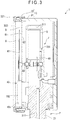
- Fig. 3 is a side cross-sectional view of the overall configuration of the inner structure of the pressure gauge 1.
- Fig. 4 is an exploded perspective view of the overall configuration of the inner structure of the pressure gauge 1.
- the pressure gauge 1 includes an introduction member 2, a case 3, a connection member 4, a bourdon tube 5, a pointer 6, a pointer transfer mechanism 7, a dial plate 8, a detector 9, and an information communication unit 10.
- the pressure gauge 1 of the exemplary embodiment is thus configured as a bourdon-tube pressure gauge.
- the introduction member 2 which is a so-called joint member attachable to a to-be-attached target such as a pipe (not shown), is in a form of a metal member of brass, stainless steel, iron and steel, or the like.
- the introduction member 2 includes a body 21 and a male thread 22 provided at a distal end portion of the body 21.
- a fluid introduction hole 211 through which a to-be-measured fluid is introduced from the to-be-attached target, is formed in the body 21.
- the male thread 22 is screwed to the to-be-attached target.
- the case 3 includes a case body 31 and a cover 32.
- the case body 31 which is made of a metal, is in a form of a bottomed cylinder, and the connection member 4, the bourdon tube 5, the pointer 6, the pointer transfer mechanism 7, the dial plate 8, the detector 9, and the information communication unit 10 are housed therein.
- the cover 32 which is disposed to cover an opening of the case body 31, is removably attachable to the case body 31. Further, the cover 32 includes a cylindrical cover body 321 and a disc-shaped transparent plate 322 attached to an opening of the cover body 321. A user can thus see the pointer 6 and the dial plate 8, which are housed in the case 3, through the transparent plate 322.
- connection member 4 which is made of a metal, is a member configured to connect the introduction member 2 to each of the bourdon tube 5 and the detector 9.
- the connection member 4 includes a connection member body 41 and an attachment plate 46. Further, the connection member body 41 is formed integral with the introduction member 2 in the exemplary embodiment. It should be noted that the configuration of the connection member body 41 is not limited to the above and, for instance, may be formed independent of the introduction member 2.
- connection member body 41 which is in a form of a block, has a first attachment side surface 42, a second attachment side surface 43, and a step 44.
- a fluid flow hole 45 is formed in the connection member body 41.
- the first attachment side surface 42 is a surface of the connection member body 41 disposed along a direction orthogonal to the dial plate 8.
- the bourdon tube 5 is attached to the first attachment side surface 42 of the connection member body 41.
- the second attachment side surface 43 is a surface of the connection member body 41 disposed along the direction orthogonal to the dial plate 8 and opposite the first attachment side surface 42.
- the detector 9 is attached to the second attachment side surface 43 of the connection member body 41. In other words, the detector 9 and the bourdon tube 5 are opposed to each other with the connection member body 41 interposed therebetween in the exemplary embodiment.
- the detector 9 is disposed at a position where the detector 9 does not interfere with the pointer transfer mechanism 7 as seen from the direction orthogonal to the dial plate 8 in the exemplary embodiment.
- the step 44 is provided to a front surface of the connection member body 41, that is, a surface facing the dial plate 8.
- the step 44 is formed to fit a shape of a unit body 101 of the later-described information communication unit 10.
- the fluid flow hole 45 is in communication with the fluid introduction hole 211 of the introduction member 2. Further, the fluid flow hole 45 is connected to a bourdon tube connector 52 of the later-described bourdon tube 5. The to-be-measured fluid is thus introduced into the bourdon tube 5 through the fluid introduction hole 211 and the fluid flow hole 45. Further, a communication tube 92 of the later-described detector 9 is connected to the fluid flow hole 45. The to-be-measured fluid is thus introduced into the detector 9 through the fluid introduction hole 211 and the fluid flow hole 45.
- the attachment plate 46 which is in an L-shape in a side cross-sectional view shown in Fig. 3 , fixes a support plate 721 of the later-described pointer transfer mechanism 7 to the case body 31.
- connection member body 41 and the attachment plate 46 are independent of each other in the exemplary embodiment, this configuration is not exhaustive and the connection member body and the attachment plate may be integral with each other.
- the bourdon tube 5 which is made of a metal, has a distal end portion displaceable according to a pressure of the to-be-measured fluid introduced therein.
- the pressure gauge 1 of the exemplary embodiment is configured to measure the pressure of the to-be-measured fluid by transferring a displacement of the bourdon tube 5 to the pointer 6 via the pointer transfer mechanism 7.
- the bourdon tube 5 includes a bourdon tube body 51 and the bourdon tube connector 52.
- the bourdon tube body 51 is formed in a semicircular shape in a plan view seen from the direction orthogonal to the dial plate 8.
- the distal end portion of the bourdon tube body 51 is displaceable according to the pressure of the to-be-measured fluid introduced therein.
- a fluid hole 511 for flowing the introduced to-be-measured fluid therein is formed in the bourdon tube body 51.
- the bourdon tube connector 52 is a member configured to connect the connection member 4 and the bourdon tube body 51 to each other.As described above, the bourdon tube connector 52 is attached to the second attachment side surface 43 of the connection member body 41 and is in communication with the fluid flow hole 45.
- the pointer 6, which is a member configured to indicate the pressure of the to-be-measured fluid detected by the bourdon tube 5, includes a pointer body 61 and a shaft 62.
- the pointer body 61 is configured to rotate around the shaft 62 (i.e., a rotation shaft), thereby pointing to a scale (not shown) displayed on the dial plate 8 according to the pressure of the to-be-measured fluid detected by the bourdon tube 5.
- the shaft 62 penetrates through a shaft insertion hole 83 formed at a center portion of the dial plate 8 while being connected to the pointer transfer mechanism 7.
- the pointer transfer mechanism 7, which is configured to amplify the displacement of the distal end portion of the bourdon tube body 51 and transfer the displacement to the pointer 6, includes a connector 71 and an internal device 72.
- the connector 71 is a member configured to connect the distal end portion of the bourdon tube body 51 to the internal device 72.
- the internal device 72 which is configured to transfer the displacement of the distal end portion of the bourdon tube body 51 to the pointer 6, includes the support plate 721, a sector 722, and a rod 723.
- the support plate 721 is a member configured to support the sector 722 and the shaft 62 of the above-described pointer 6.
- the support plate 721 is attached to the case body 31 via the attachment plate 46.
- the sector 722 is a member configured to transfer the displacement of the distal end portion of the bourdon tube body 51 to the shaft 62 through the connector 71 and the rod 723.
- the sector 722 is rotatably supported by the above-described support plate 721.
- the rod 723 which is a member configured to connect the connector 71 to the sector 722, is rotatably supported by the connector 71.
- the dial plate 8 which is disposed so as to face the transparent plate 322 of the cover 32, has a front surface 81 displaying the scale (not shown).Thus, the pressure gauge 1 can display the pressure of the to-be-measured fluid by the pointer body 61 pointing to the scale.
- the dial plate 8 has a shaft insertion hole 83 and a through hole 84 each penetrating the dial plate 8 from the front surface 81 to the rear surface 82.
- the unit body 101 of the later-described information communication unit 10 is inserted in the through hole 84.
- the detector 9 is a member configured to detect the pressure of the to-be-measured fluid and output a signal corresponding to the detected pressure.
- the sensor element 91 includes a diaphragm 911 and a cylindrical portion 912.
- the diaphragm 911 is configured to be deformed according to the pressure of the introduced to-be-measured fluid.
- the cylindrical portion 912 supports the diaphragm 911 at one distal end portion thereof.
- the other end portion of the cylindrical portion 912 is connected to the communication tube 92.
- the to-be-measured fluid is introduced into the cylindrical portion 912 through the communication tube 92.
- a strain gauge (not shown) configured to detect a deformation of the diaphragm 911 is disposed in the diaphragm 911.
- the sensor element 91 is thus configured to output the signal corresponding to the pressure of the to-be-measured.
- the sensor element 91 is configured as a strain-gauge pressure sensor element in the exemplary embodiment. It should be noted that the configuration of the sensor element 91 is not limited to the above, and the sensor element 91 may be configured as, for instance, a capacitive pressure sensor element. It is only required that the sensor element 91 detects the pressure of the to-be-measured fluid.
- the communication tube 92 is welded to the second attachment side surface 43 of the connection member body 41. One end of the communication tube 92 is in communication with the fluid flow hole 45 as described above. The other end of the communication tube 92 is bonded to the sensor element 91. With this configuration, the communication tube 92 can introduce the to-be-measured fluid flowing through the fluid flow hole 45 into the sensor element 91.
- the communication tube 92 and the second attachment side surface 43 of the connection member body 41 are laser-welded to each other in the exemplary embodiment. Since a focal length between a torch of a welding device and a welded point can be adjusted in the laser welding, interference between the torch and the bourdon tube 5 can be restrained during a welding operation. Further, since the laser welding enables local heating and further the sensor element 91 is connected to the connection member body 41 through the communication tube 92, heat at the welding can be restrained from being transferred to the sensor element 91.
- Fig. 5 is a front view of an overall configuration of an inner structure of the information communication unit 10. It should be noted that Fig. 5 shows a state where a lid 102 is removed.
- the information communication unit 10 includes the unit body 101, the lid 102, a battery 103, a circuit board 104, and an antenna 105.
- the information communication unit 10 is configured to send and receive an electric wave of Bluetooth (Registered trademark).
- the information communication unit 10 can thus output a signal outputted from the sensor element 91 to an external device.
- the configuration of the information communication unit 10 is not limited to the above and may be configured to send and receive, for instance, an electric wave or an infrared light of Wi-Fi (Registered trademark) or NFC.
- the circuit board 104 may include a storage. Such a configuration enables the circuit board 104 to, for instance, store data corresponding to the signal outputted from the sensor element 91 and, when predetermined data is stored, output the data through the antenna 105.
- the unit body 101 which is in a form of a resin-made bottomed cylinder, is inserted in the through hole 84 of the dial plate 8 as described above.
- the unit body 101 is thus disposed astride between the front surface 81 and the rear surface 82 of the dial plate 8. Further, the unit body 101 is disposed in the step 44 of the connection member body 41 in the exemplary embodiment.
- the lid 102 which is removably attachable to the unit body 101, is disposed to cover an opening of the unit body 101. Further, the lid 102 is disposed on a side of the unit body 101 close to the front surface 81 of the dial plate 8 such that the lid 102 faces the transparent plate 322 of the cover 32. Thus, it is only necessary to remove the case body 31 from the cover 32 to attach or remove the lid 102 to or from the unit body 101.
- the single battery 103 which is installed in the unit body 101, is configured to supply power to the circuit board 104.
- the battery 103 is a so-called button battery or coin battery.
- the configuration of the battery 103 is not limited to the above and may be configured as, for instance, a cylindrical dry cell, a cylindrical rechargeable battery, or a polymer battery. Further, a plurality of batteries 103 may be installed in the unit body 101.
- the circuit board 104 on which an electronic component, etc. (not shown) are mounted, is electrically connected to the sensor element 91 of the detector 9.With this configuration, the signal outputted from the sensor element 91 can be inputted to the circuit board 104.
- the circuit board 104 is built in the unit body 101 behind the battery 103, that is, on a side of the battery 103 facing the connection member 4. In other words, the battery 103 is disposed between the lid 102 and the circuit board 104.
- the circuit board 104 is provided with the antenna 105 configured as a pattern antenna.
- the circuit board 104 can thus send and receive an electric wave to and from an external device through the antenna 105.
- the circuit board 104 can output the signal inputted from the sensor element 91 to the external device through the antenna 105.
- a signal from the external device such as a signal for adjusting output of the circuit board 104, can be inputted to the circuit board 104 through the antenna 105.
- the configuration of the antenna 105 is not limited to the above and the antenna 105 may be configured as, for instance, a dipole antenna or a chip antenna.
- the antenna 105 is disposed at a position where at least a part of the antenna 105 is not overlaid with the battery 103 as seen from the direction orthogonal to the dial plate 8 in the exemplary embodiment.
- the battery 103 in sending or receiving an electric wave to or from an external device through the antenna 105, the battery 103 is not disposed at least at a part of an electric wave transmission path. This allows for restraining interference of the battery 103 with the electric wave to improve a sending/receiving sensitivity of the antenna 105 to the electric wave.
- the exemplary embodiment as described above can achieve the following effects.
- the introduction member 2 includes the male thread 22 but the configuration of the introduction member 2 is not limited thereto.
- the introduction member may include a female thread or may be welded to a to-be-attached target.
- the case body 31 is made of a metal but a material of the case body 31 is not limited thereto.
- the case body may be made of a resin.
- the case body 31 is in the form of a bottomed cylinder but the case body 31 may be in any form.
- the case body may be a bottomed rectangular prism or only has to be configured to allow the connection member, the bourdon tube, the pointer, the pointer transfer mechanism, the dial plate, the detector, the information communication unit, etc. to be housed therein.
- the antenna 105 is disposed at a position where at least a part of the antenna 105 is not overlaid with the battery 103 as seen from the direction orthogonal to the dial plate 8, but the antenna 105 may be at any position.
- the antenna may be disposed at a position where the antenna is not overlaid with the battery at all as seen from the direction orthogonal to the dial plate.
- a case where the antenna is fully overlaid with the battery also falls within the scope of the invention.
- connection member 4 has the step 44 to fit a shape of the unit body 101 but the configuration of the connection member 4 is not limited thereto. For instance, a case where the connection member is provided with no step also falls within the scope of the invention.
- Fig. 6 is a perspective view of an overall configuration of a pressure gauge 1A according to a modification.
- a transparent plate 322A of a cover 32A of a case 3A may be provided with a hole 3221A at a position corresponding to an information communication unit 10A.
- the lid 102 can be removed through the hole 3221A without the necessity of removing the cover 32A, so that a battery installed in the information communication unit 10A can be easily replaced.
- the information communication unit 10A may be provided with a communication port 106A.
- a communication port 106A In such a configuration, with a cable or a recording medium being connected to the communication port 106A, communication with an external device can be performed through the cable or the recording medium.
- the circuit board may be provided with no antenna.
- Fig. 7 is a perspective view of an overall configuration of a pressure gauge 1B according to another modification.
- a transparent plate 322B of a cover 32B may be provided with a hole 3221B and an information communication unit 10B may be disposed such that the information communication unit 10B partially projects outside a case 3B through the hole 3221B.
- the lid 102 since the lid 102 is disposed to an external side of the case 3B and can be removed without removing the cover 32B, a battery installed in the information communication unit 10B can be easily replaced.
Landscapes
- Physics & Mathematics (AREA)
- General Physics & Mathematics (AREA)
- Measuring Fluid Pressure (AREA)
Claims (9)
- Druckmesser (1, 1A, 1B), aufweisend:ein Einleitungselement (2) mit einem Fluideinleitungsloch (211), in das ein zu messendes Fluid eingeleitet wird;ein Verbindungselement (4) mit einem Fluidströmungsloch (45), das mit dem Fluideinleitungsloch (211) in Verbindung steht;ein Bourdon-Rohr (5), das am Verbindungselement (4) angebracht ist und mit dem Fluidströmungsloch (45) in Verbindung steht;einen Zeiger (6), der ausgestaltet ist, um sich in Verbindung mit einer Verschiebung eines distalen Endabschnitts des Bourdon-Rohres (5) zu drehen;eine Skalentafel (8) mit einer Vorderseite (81), auf der eine durch den Zeiger (6) anzuzeigende Skala angezeigt ist und die ein Durchgangsloch (84) hat, das sich von der Vorderseite (81) zu einer Rückseite (82) durchsetzt;einen Detektor (9), der ausgestaltet ist, um einen Druck des zu messenden Fluids zu erfassen, und der am Verbindungselement (4) angebracht ist; undeine Informationskommunikationseinheit (10, 10A, 10B), in der eine elektrisch mit dem Detektor (9) verbundene Leiterplatte (104) und eine Batterie (103) installiert sind,wobei der Druckmesser dadurch gekennzeichnet ist, dass die Informationskommunikationseinheit (10, 10A, 10B) einen mit einem Boden versehenen zylindrischen Einheitskörper (101) und eine eine Öffnung des Einheitskörpers (101) abdeckende Kappe (102) aufweist, wobeidie Batterie (103) zwischen der Leiterplatte (104) und der Kappe (102) angeordnet ist,die Informationskommunikationseinheit (10, 10A, 10B) im Durchgangsloch (84) eingesetzt ist, um rittlings zwischen der Vorderseite (81) und der Rückseite (82) der Skalentafel (8) angeordnet zu sein, unddie Kappe (102) an einer Seite des Einheitskörpers nahe der Vorderseite (81) der Skalentafel (8) angeordnet ist.
- Druckmesser (1) nach Anspruch 1, ferner aufweisend:ein Gehäuse (3) mit einem mit einem Boden versehenen zylindrischen Gehäusekörper (31) und einem Deckel (32), der eine Öffnung des Gehäusekörpers (31) abdeckt, wobei das Gehäuse (3) darin das Verbindungselement (4), das Bourdon-Rohr (5), den Zeiger (6), die Skalentafel (8), den Detektor (9) und die Informationskommunikationseinheit (10) unterbringt, wobeidie Kappe (102) dem Deckel (32) zugewandt angeordnet ist.
- Druckmesser (1A, 1B) nach Anspruch 1, ferner aufweisend:ein Gehäuse (3A, 3B) mit einem mit einem Boden versehenen zylindrischen Gehäusekörper (31) und einem Deckel (32A, 32B), der eine Öffnung des Gehäusekörpers (31) abdeckt, wobei das Gehäuse (3A, 3B) darin das Verbindungselement (4), das Bourdon-Rohr (5), den Zeiger (6), die Skalentafel (8), den Detektor (9) und die Informationskommunikationseinheit (10A, 10B) unterbringt, wobeider Deckel (32A, 32B) ein Loch (3221A, 3221B) an einer Position entsprechend der Informationskommunikationseinheit (10A, 10B) hat.
- Druckmesser (1B) nach Anspruch 3, bei welchem
die Informationskommunikationseinheit (10B) in einer Weise angeordnet ist, um durch das Loch (3221B) teilweise aus dem Gehäuse (3B) herauszuragen, und die Kappe (102) an einer Außenseite des Gehäuses (3B) angeordnet. - Druckmesser (1, 1A, 1B) nach einem der Ansprüche 1 bis 4, bei welchemdie Informationskommunikationseinheit (10, 10A, 10B) ferner eine Antenne (105) aufweist, die an der Leiterplatte (104) vorgesehen ist, unddie Antenne (105) an einer Position angeordnet ist, wo zumindest ein Teil der Antenne nicht über der Batterie (103) liegt, gesehen aus einer Richtung orthogonal zur Skalentafel (8).
- Druckmesser (1, 1A, 1B) nach einem der Ansprüche 1 bis 5, bei welchem das Verbindungselement (4) eine Stufe (44) aufweist, um sich einer Form des Einheitskörpers (101) anzupassen.
- Druckmesser (1, 1A, 1B) nach einem der Ansprüche 1 bis 6, bei welchemdas Verbindungselement (4) in Form eines Blocks vorliegt und eine erste Befestigungsseite (42), die entlang einer Richtung orthogonal zur Skalentafel (8) angeordnet ist, und eine zweite Befestigungsseite (43), die entlang der Richtung orthogonal zur Skalentafel (8) und gegenüber der ersten Befestigungsseite (42) angeordnet ist, hat,das Bourdon-Rohr (5) an der ersten Befestigungsseite (42) des Verbindungselements (4) angebracht ist, undder Detektor (9) an der zweiten Befestigungsseiten (43) des Verbindungselements (4) angebracht ist.
- Druckmesser (1, 1A, 1B) nach Anspruch 7, bei welchemder Detektor (9) ein Sensorelement (91), das konfiguriert ist, um den Druck des zu messenden Fluids zu erfassen, und ein Verbindungsrohr (92), durch welches das Sensorelement (91) und das Fluidströmungsloch (45) miteinander in Verbindung stehen, aufweist,das Verbindungselement (4) und das Verbindungsrohr (92) jeweils aus einem Metall gemacht sind, unddas Verbindungsrohr (92) und die zweite Befestigungsseite (43) miteinander verschweißt sind.
- Druckmesser (1, 1A, 1B) nach einem der Ansprüche 1 bis 8, ferner aufweisend:einen Zeigerübertragungsmechanismus (7), der ausgestaltet ist, um die Verschiebung des distalen Endabschnitts des Bourdon-Rohres (5) auf den Zeiger (6) zu übertragen, wobeider Detektor (9) an einer Position angeordnet ist, wo der Detektor nicht den Zeigerübertragungsmechanismus (7) stört.
Applications Claiming Priority (1)
| Application Number | Priority Date | Filing Date | Title |
|---|---|---|---|
| JP2019198560A JP7050039B2 (ja) | 2019-10-31 | 2019-10-31 | 圧力計 |
Publications (2)
| Publication Number | Publication Date |
|---|---|
| EP3816601A1 EP3816601A1 (de) | 2021-05-05 |
| EP3816601B1 true EP3816601B1 (de) | 2021-10-27 |
Family
ID=74095643
Family Applications (1)
| Application Number | Title | Priority Date | Filing Date |
|---|---|---|---|
| EP20204776.7A Active EP3816601B1 (de) | 2019-10-31 | 2020-10-29 | Drucksensor |
Country Status (4)
| Country | Link |
|---|---|
| US (1) | US11346736B2 (de) |
| EP (1) | EP3816601B1 (de) |
| JP (1) | JP7050039B2 (de) |
| CN (1) | CN112747857A (de) |
Family Cites Families (12)
| Publication number | Priority date | Publication date | Assignee | Title |
|---|---|---|---|---|
| US3828611A (en) * | 1972-11-10 | 1974-08-13 | Farallon Ind | Portable underwater indicating instrument for divers |
| US3888127A (en) * | 1972-11-10 | 1975-06-10 | Farallon Ind | Portable underwater indicating instrument for divers |
| JPH10288560A (ja) * | 1997-04-15 | 1998-10-27 | Nagano:Kk | 流体物理量測定器 |
| US7140257B2 (en) | 2002-12-10 | 2006-11-28 | Ashcroft Inc. | Wireless transmitting pressure measurement device |
| JP4806274B2 (ja) | 2006-03-09 | 2011-11-02 | 有限会社ティーアンドエス | スキューバダイビング用圧力ゲージ |
| US7599469B2 (en) * | 2006-04-28 | 2009-10-06 | Cameron International Corporation | Non-intrusive pressure gage |
| US7716990B1 (en) | 2008-04-02 | 2010-05-18 | Cps Products, Inc. | Portable electroluminescent diagnostic gauge |
| US20120227662A1 (en) * | 2011-03-08 | 2012-09-13 | Air Lift Company | Pressure gauge with integral input and valve |
| JP6154623B2 (ja) | 2013-02-28 | 2017-06-28 | 長野計器株式会社 | 圧力計 |
| US20160109312A1 (en) | 2014-10-15 | 2016-04-21 | Clark Equipment Company | Pressure gauge with digital display |
| WO2017195251A1 (ja) | 2016-05-09 | 2017-11-16 | 株式会社木幡計器製作所 | 計器用icタグユニット、計器用icタグシステム、icタグユニットを備えた計器及びicタグユニットを備えた計器の校正方法 |
| US10416035B2 (en) | 2017-05-30 | 2019-09-17 | Mija Industries, Inc. | Power management system for pressure monitoring |
-
2019
- 2019-10-31 JP JP2019198560A patent/JP7050039B2/ja active Active
-
2020
- 2020-10-28 US US17/082,204 patent/US11346736B2/en active Active
- 2020-10-29 EP EP20204776.7A patent/EP3816601B1/de active Active
- 2020-10-30 CN CN202011195641.9A patent/CN112747857A/zh active Pending
Also Published As
| Publication number | Publication date |
|---|---|
| JP2021071402A (ja) | 2021-05-06 |
| EP3816601A1 (de) | 2021-05-05 |
| CN112747857A (zh) | 2021-05-04 |
| JP7050039B2 (ja) | 2022-04-07 |
| US11346736B2 (en) | 2022-05-31 |
| US20210131896A1 (en) | 2021-05-06 |
Similar Documents
| Publication | Publication Date | Title |
|---|---|---|
| US9404815B2 (en) | Superheat sensor having external temperature sensor | |
| CA2249191C (en) | Measuring indicator attachment | |
| US9581485B2 (en) | Removable magnetostrictive probe with automatic calibration | |
| CN102356307B (zh) | 具有真空电介质的电容性表压传感器 | |
| CN102058398B (zh) | 耳式体温计以及在耳式体温计中使用的测定装置主体 | |
| EP3660478B1 (de) | Sensoranordnung und vorrichtung zur messung physikalischer mengen | |
| EP3816601B1 (de) | Drucksensor | |
| CA2957227C (en) | Rotatable and removable multi-pin explosion proof connector assembly | |
| WO2019044280A1 (ja) | 出力システム及び計器 | |
| US10175134B2 (en) | Physical quantity measuring device | |
| US6510741B2 (en) | Manometer having dual pressure sensors | |
| JP2017203775A5 (de) | ||
| JP2007178214A (ja) | 空気圧検知システム | |
| JPH10288560A (ja) | 流体物理量測定器 | |
| EP1238246B1 (de) | Gerät und system zur messung eines parameters in einem geschlossenen raum | |
| JP6154623B2 (ja) | 圧力計 | |
| CN220356990U (zh) | 基于超声波的液体浓度测量装置 | |
| JP2024018206A (ja) | 指針読取装置、物理量測定装置、指針読取装置の取り付け方法 | |
| JP2024062069A (ja) | 荷重測定装置 | |
| JPH036435A (ja) | 差圧・圧力発信器 | |
| CN112504521A (zh) | 轴销式力传感器 | |
| JP2021139759A (ja) | 圧力センサ | |
| JP2004045217A (ja) | 圧力センサ | |
| JP2004037271A (ja) | 圧力センサ | |
| JPH10290520A (ja) | 流体物理量に応じて動作するスイッチ |
Legal Events
| Date | Code | Title | Description |
|---|---|---|---|
| PUAI | Public reference made under article 153(3) epc to a published international application that has entered the european phase |
Free format text: ORIGINAL CODE: 0009012 |
|
| STAA | Information on the status of an ep patent application or granted ep patent |
Free format text: STATUS: THE APPLICATION HAS BEEN PUBLISHED |
|
| AK | Designated contracting states |
Kind code of ref document: A1 Designated state(s): AL AT BE BG CH CY CZ DE DK EE ES FI FR GB GR HR HU IE IS IT LI LT LU LV MC MK MT NL NO PL PT RO RS SE SI SK SM TR |
|
| STAA | Information on the status of an ep patent application or granted ep patent |
Free format text: STATUS: REQUEST FOR EXAMINATION WAS MADE |
|
| 17P | Request for examination filed |
Effective date: 20210607 |
|
| RBV | Designated contracting states (corrected) |
Designated state(s): AL AT BE BG CH CY CZ DE DK EE ES FI FR GB GR HR HU IE IS IT LI LT LU LV MC MK MT NL NO PL PT RO RS SE SI SK SM TR |
|
| GRAP | Despatch of communication of intention to grant a patent |
Free format text: ORIGINAL CODE: EPIDOSNIGR1 |
|
| STAA | Information on the status of an ep patent application or granted ep patent |
Free format text: STATUS: GRANT OF PATENT IS INTENDED |
|
| RIN1 | Information on inventor provided before grant (corrected) |
Inventor name: KANEKO, HIROYUKI Inventor name: MIZUKOSHI, TAKAYUKI Inventor name: SHIOIRI, SHOTA Inventor name: YANAGISAWA, MASAKI Inventor name: SAKA, HIDENORI Inventor name: HASHIMOTO, YUTAKU |
|
| INTG | Intention to grant announced |
Effective date: 20210728 |
|
| GRAS | Grant fee paid |
Free format text: ORIGINAL CODE: EPIDOSNIGR3 |
|
| GRAA | (expected) grant |
Free format text: ORIGINAL CODE: 0009210 |
|
| STAA | Information on the status of an ep patent application or granted ep patent |
Free format text: STATUS: THE PATENT HAS BEEN GRANTED |
|
| AK | Designated contracting states |
Kind code of ref document: B1 Designated state(s): AL AT BE BG CH CY CZ DE DK EE ES FI FR GB GR HR HU IE IS IT LI LT LU LV MC MK MT NL NO PL PT RO RS SE SI SK SM TR |
|
| REG | Reference to a national code |
Ref country code: GB Ref legal event code: FG4D |
|
| REG | Reference to a national code |
Ref country code: CH Ref legal event code: EP |
|
| REG | Reference to a national code |
Ref country code: DE Ref legal event code: R096 Ref document number: 602020000851 Country of ref document: DE |
|
| REG | Reference to a national code |
Ref country code: AT Ref legal event code: REF Ref document number: 1442202 Country of ref document: AT Kind code of ref document: T Effective date: 20211115 |
|
| REG | Reference to a national code |
Ref country code: IE Ref legal event code: FG4D |
|
| REG | Reference to a national code |
Ref country code: LT Ref legal event code: MG9D |
|
| REG | Reference to a national code |
Ref country code: NL Ref legal event code: MP Effective date: 20211027 |
|
| REG | Reference to a national code |
Ref country code: AT Ref legal event code: MK05 Ref document number: 1442202 Country of ref document: AT Kind code of ref document: T Effective date: 20211027 |
|
| PG25 | Lapsed in a contracting state [announced via postgrant information from national office to epo] |
Ref country code: RS Free format text: LAPSE BECAUSE OF FAILURE TO SUBMIT A TRANSLATION OF THE DESCRIPTION OR TO PAY THE FEE WITHIN THE PRESCRIBED TIME-LIMIT Effective date: 20211027 Ref country code: LT Free format text: LAPSE BECAUSE OF FAILURE TO SUBMIT A TRANSLATION OF THE DESCRIPTION OR TO PAY THE FEE WITHIN THE PRESCRIBED TIME-LIMIT Effective date: 20211027 Ref country code: FI Free format text: LAPSE BECAUSE OF FAILURE TO SUBMIT A TRANSLATION OF THE DESCRIPTION OR TO PAY THE FEE WITHIN THE PRESCRIBED TIME-LIMIT Effective date: 20211027 Ref country code: BG Free format text: LAPSE BECAUSE OF FAILURE TO SUBMIT A TRANSLATION OF THE DESCRIPTION OR TO PAY THE FEE WITHIN THE PRESCRIBED TIME-LIMIT Effective date: 20220127 Ref country code: AT Free format text: LAPSE BECAUSE OF FAILURE TO SUBMIT A TRANSLATION OF THE DESCRIPTION OR TO PAY THE FEE WITHIN THE PRESCRIBED TIME-LIMIT Effective date: 20211027 |
|
| PG25 | Lapsed in a contracting state [announced via postgrant information from national office to epo] |
Ref country code: IS Free format text: LAPSE BECAUSE OF FAILURE TO SUBMIT A TRANSLATION OF THE DESCRIPTION OR TO PAY THE FEE WITHIN THE PRESCRIBED TIME-LIMIT Effective date: 20220227 Ref country code: SE Free format text: LAPSE BECAUSE OF FAILURE TO SUBMIT A TRANSLATION OF THE DESCRIPTION OR TO PAY THE FEE WITHIN THE PRESCRIBED TIME-LIMIT Effective date: 20211027 Ref country code: PT Free format text: LAPSE BECAUSE OF FAILURE TO SUBMIT A TRANSLATION OF THE DESCRIPTION OR TO PAY THE FEE WITHIN THE PRESCRIBED TIME-LIMIT Effective date: 20220228 Ref country code: PL Free format text: LAPSE BECAUSE OF FAILURE TO SUBMIT A TRANSLATION OF THE DESCRIPTION OR TO PAY THE FEE WITHIN THE PRESCRIBED TIME-LIMIT Effective date: 20211027 Ref country code: NO Free format text: LAPSE BECAUSE OF FAILURE TO SUBMIT A TRANSLATION OF THE DESCRIPTION OR TO PAY THE FEE WITHIN THE PRESCRIBED TIME-LIMIT Effective date: 20220127 Ref country code: NL Free format text: LAPSE BECAUSE OF FAILURE TO SUBMIT A TRANSLATION OF THE DESCRIPTION OR TO PAY THE FEE WITHIN THE PRESCRIBED TIME-LIMIT Effective date: 20211027 Ref country code: LV Free format text: LAPSE BECAUSE OF FAILURE TO SUBMIT A TRANSLATION OF THE DESCRIPTION OR TO PAY THE FEE WITHIN THE PRESCRIBED TIME-LIMIT Effective date: 20211027 Ref country code: HR Free format text: LAPSE BECAUSE OF FAILURE TO SUBMIT A TRANSLATION OF THE DESCRIPTION OR TO PAY THE FEE WITHIN THE PRESCRIBED TIME-LIMIT Effective date: 20211027 Ref country code: GR Free format text: LAPSE BECAUSE OF FAILURE TO SUBMIT A TRANSLATION OF THE DESCRIPTION OR TO PAY THE FEE WITHIN THE PRESCRIBED TIME-LIMIT Effective date: 20220128 Ref country code: ES Free format text: LAPSE BECAUSE OF FAILURE TO SUBMIT A TRANSLATION OF THE DESCRIPTION OR TO PAY THE FEE WITHIN THE PRESCRIBED TIME-LIMIT Effective date: 20211027 |
|
| REG | Reference to a national code |
Ref country code: DE Ref legal event code: R097 Ref document number: 602020000851 Country of ref document: DE |
|
| PG25 | Lapsed in a contracting state [announced via postgrant information from national office to epo] |
Ref country code: SM Free format text: LAPSE BECAUSE OF FAILURE TO SUBMIT A TRANSLATION OF THE DESCRIPTION OR TO PAY THE FEE WITHIN THE PRESCRIBED TIME-LIMIT Effective date: 20211027 Ref country code: SK Free format text: LAPSE BECAUSE OF FAILURE TO SUBMIT A TRANSLATION OF THE DESCRIPTION OR TO PAY THE FEE WITHIN THE PRESCRIBED TIME-LIMIT Effective date: 20211027 Ref country code: RO Free format text: LAPSE BECAUSE OF FAILURE TO SUBMIT A TRANSLATION OF THE DESCRIPTION OR TO PAY THE FEE WITHIN THE PRESCRIBED TIME-LIMIT Effective date: 20211027 Ref country code: MC Free format text: LAPSE BECAUSE OF FAILURE TO SUBMIT A TRANSLATION OF THE DESCRIPTION OR TO PAY THE FEE WITHIN THE PRESCRIBED TIME-LIMIT Effective date: 20211027 Ref country code: EE Free format text: LAPSE BECAUSE OF FAILURE TO SUBMIT A TRANSLATION OF THE DESCRIPTION OR TO PAY THE FEE WITHIN THE PRESCRIBED TIME-LIMIT Effective date: 20211027 Ref country code: DK Free format text: LAPSE BECAUSE OF FAILURE TO SUBMIT A TRANSLATION OF THE DESCRIPTION OR TO PAY THE FEE WITHIN THE PRESCRIBED TIME-LIMIT Effective date: 20211027 Ref country code: CZ Free format text: LAPSE BECAUSE OF FAILURE TO SUBMIT A TRANSLATION OF THE DESCRIPTION OR TO PAY THE FEE WITHIN THE PRESCRIBED TIME-LIMIT Effective date: 20211027 |
|
| PLBE | No opposition filed within time limit |
Free format text: ORIGINAL CODE: 0009261 |
|
| STAA | Information on the status of an ep patent application or granted ep patent |
Free format text: STATUS: NO OPPOSITION FILED WITHIN TIME LIMIT |
|
| 26N | No opposition filed |
Effective date: 20220728 |
|
| PG25 | Lapsed in a contracting state [announced via postgrant information from national office to epo] |
Ref country code: AL Free format text: LAPSE BECAUSE OF FAILURE TO SUBMIT A TRANSLATION OF THE DESCRIPTION OR TO PAY THE FEE WITHIN THE PRESCRIBED TIME-LIMIT Effective date: 20211027 |
|
| PG25 | Lapsed in a contracting state [announced via postgrant information from national office to epo] |
Ref country code: FR Free format text: LAPSE BECAUSE OF NON-PAYMENT OF DUE FEES Effective date: 20211227 |
|
| PG25 | Lapsed in a contracting state [announced via postgrant information from national office to epo] |
Ref country code: IT Free format text: LAPSE BECAUSE OF FAILURE TO SUBMIT A TRANSLATION OF THE DESCRIPTION OR TO PAY THE FEE WITHIN THE PRESCRIBED TIME-LIMIT Effective date: 20211027 |
|
| REG | Reference to a national code |
Ref country code: BE Ref legal event code: MM Effective date: 20221031 |
|
| PG25 | Lapsed in a contracting state [announced via postgrant information from national office to epo] |
Ref country code: LU Free format text: LAPSE BECAUSE OF NON-PAYMENT OF DUE FEES Effective date: 20221029 |
|
| PG25 | Lapsed in a contracting state [announced via postgrant information from national office to epo] |
Ref country code: HU Free format text: LAPSE BECAUSE OF FAILURE TO SUBMIT A TRANSLATION OF THE DESCRIPTION OR TO PAY THE FEE WITHIN THE PRESCRIBED TIME-LIMIT; INVALID AB INITIO Effective date: 20201029 |
|
| PG25 | Lapsed in a contracting state [announced via postgrant information from national office to epo] |
Ref country code: BE Free format text: LAPSE BECAUSE OF NON-PAYMENT OF DUE FEES Effective date: 20221031 |
|
| PG25 | Lapsed in a contracting state [announced via postgrant information from national office to epo] |
Ref country code: IE Free format text: LAPSE BECAUSE OF NON-PAYMENT OF DUE FEES Effective date: 20221029 |
|
| PGFP | Annual fee paid to national office [announced via postgrant information from national office to epo] |
Ref country code: DE Payment date: 20230904 Year of fee payment: 4 |
|
| PG25 | Lapsed in a contracting state [announced via postgrant information from national office to epo] |
Ref country code: CY Free format text: LAPSE BECAUSE OF FAILURE TO SUBMIT A TRANSLATION OF THE DESCRIPTION OR TO PAY THE FEE WITHIN THE PRESCRIBED TIME-LIMIT Effective date: 20211027 |
|
| PG25 | Lapsed in a contracting state [announced via postgrant information from national office to epo] |
Ref country code: MK Free format text: LAPSE BECAUSE OF FAILURE TO SUBMIT A TRANSLATION OF THE DESCRIPTION OR TO PAY THE FEE WITHIN THE PRESCRIBED TIME-LIMIT Effective date: 20211027 |
|
| REG | Reference to a national code |
Ref country code: CH Ref legal event code: PL |
|
| PG25 | Lapsed in a contracting state [announced via postgrant information from national office to epo] |
Ref country code: CH Free format text: LAPSE BECAUSE OF NON-PAYMENT OF DUE FEES Effective date: 20231031 |
|
| PG25 | Lapsed in a contracting state [announced via postgrant information from national office to epo] |
Ref country code: CH Free format text: LAPSE BECAUSE OF NON-PAYMENT OF DUE FEES Effective date: 20231031 |
|
| PG25 | Lapsed in a contracting state [announced via postgrant information from national office to epo] |
Ref country code: MT Free format text: LAPSE BECAUSE OF FAILURE TO SUBMIT A TRANSLATION OF THE DESCRIPTION OR TO PAY THE FEE WITHIN THE PRESCRIBED TIME-LIMIT Effective date: 20211027 |