EP3816136A1 - Ceramic sintered body and member for plasma treatment device - Google Patents
Ceramic sintered body and member for plasma treatment device Download PDFInfo
- Publication number
- EP3816136A1 EP3816136A1 EP19824889.0A EP19824889A EP3816136A1 EP 3816136 A1 EP3816136 A1 EP 3816136A1 EP 19824889 A EP19824889 A EP 19824889A EP 3816136 A1 EP3816136 A1 EP 3816136A1
- Authority
- EP
- European Patent Office
- Prior art keywords
- peripheral surface
- cylindrical body
- yttrium
- ceramic sintered
- processing apparatus
- Prior art date
- Legal status (The legal status is an assumption and is not a legal conclusion. Google has not performed a legal analysis and makes no representation as to the accuracy of the status listed.)
- Withdrawn
Links
Images


Classifications
-
- H—ELECTRICITY
- H01—ELECTRIC ELEMENTS
- H01J—ELECTRIC DISCHARGE TUBES OR DISCHARGE LAMPS
- H01J37/00—Discharge tubes with provision for introducing objects or material to be exposed to the discharge, e.g. for the purpose of examination or processing thereof
- H01J37/32—Gas-filled discharge tubes
- H01J37/32431—Constructional details of the reactor
- H01J37/32458—Vessel
- H01J37/32467—Material
-
- H—ELECTRICITY
- H01—ELECTRIC ELEMENTS
- H01J—ELECTRIC DISCHARGE TUBES OR DISCHARGE LAMPS
- H01J37/00—Discharge tubes with provision for introducing objects or material to be exposed to the discharge, e.g. for the purpose of examination or processing thereof
- H01J37/32—Gas-filled discharge tubes
- H01J37/32431—Constructional details of the reactor
- H01J37/32715—Workpiece holder
-
- C—CHEMISTRY; METALLURGY
- C04—CEMENTS; CONCRETE; ARTIFICIAL STONE; CERAMICS; REFRACTORIES
- C04B—LIME, MAGNESIA; SLAG; CEMENTS; COMPOSITIONS THEREOF, e.g. MORTARS, CONCRETE OR LIKE BUILDING MATERIALS; ARTIFICIAL STONE; CERAMICS; REFRACTORIES; TREATMENT OF NATURAL STONE
- C04B35/00—Shaped ceramic products characterised by their composition; Ceramics compositions; Processing powders of inorganic compounds preparatory to the manufacturing of ceramic products
- C04B35/01—Shaped ceramic products characterised by their composition; Ceramics compositions; Processing powders of inorganic compounds preparatory to the manufacturing of ceramic products based on oxide ceramics
- C04B35/44—Shaped ceramic products characterised by their composition; Ceramics compositions; Processing powders of inorganic compounds preparatory to the manufacturing of ceramic products based on oxide ceramics based on aluminates
-
- C—CHEMISTRY; METALLURGY
- C04—CEMENTS; CONCRETE; ARTIFICIAL STONE; CERAMICS; REFRACTORIES
- C04B—LIME, MAGNESIA; SLAG; CEMENTS; COMPOSITIONS THEREOF, e.g. MORTARS, CONCRETE OR LIKE BUILDING MATERIALS; ARTIFICIAL STONE; CERAMICS; REFRACTORIES; TREATMENT OF NATURAL STONE
- C04B35/00—Shaped ceramic products characterised by their composition; Ceramics compositions; Processing powders of inorganic compounds preparatory to the manufacturing of ceramic products
- C04B35/50—Shaped ceramic products characterised by their composition; Ceramics compositions; Processing powders of inorganic compounds preparatory to the manufacturing of ceramic products based on rare-earth compounds
- C04B35/505—Shaped ceramic products characterised by their composition; Ceramics compositions; Processing powders of inorganic compounds preparatory to the manufacturing of ceramic products based on rare-earth compounds based on yttrium oxide
-
- C—CHEMISTRY; METALLURGY
- C04—CEMENTS; CONCRETE; ARTIFICIAL STONE; CERAMICS; REFRACTORIES
- C04B—LIME, MAGNESIA; SLAG; CEMENTS; COMPOSITIONS THEREOF, e.g. MORTARS, CONCRETE OR LIKE BUILDING MATERIALS; ARTIFICIAL STONE; CERAMICS; REFRACTORIES; TREATMENT OF NATURAL STONE
- C04B35/00—Shaped ceramic products characterised by their composition; Ceramics compositions; Processing powders of inorganic compounds preparatory to the manufacturing of ceramic products
- C04B35/622—Forming processes; Processing powders of inorganic compounds preparatory to the manufacturing of ceramic products
- C04B35/626—Preparing or treating the powders individually or as batches ; preparing or treating macroscopic reinforcing agents for ceramic products, e.g. fibres; mechanical aspects section B
- C04B35/63—Preparing or treating the powders individually or as batches ; preparing or treating macroscopic reinforcing agents for ceramic products, e.g. fibres; mechanical aspects section B using additives specially adapted for forming the products, e.g.. binder binders
- C04B35/632—Organic additives
-
- C—CHEMISTRY; METALLURGY
- C04—CEMENTS; CONCRETE; ARTIFICIAL STONE; CERAMICS; REFRACTORIES
- C04B—LIME, MAGNESIA; SLAG; CEMENTS; COMPOSITIONS THEREOF, e.g. MORTARS, CONCRETE OR LIKE BUILDING MATERIALS; ARTIFICIAL STONE; CERAMICS; REFRACTORIES; TREATMENT OF NATURAL STONE
- C04B35/00—Shaped ceramic products characterised by their composition; Ceramics compositions; Processing powders of inorganic compounds preparatory to the manufacturing of ceramic products
- C04B35/622—Forming processes; Processing powders of inorganic compounds preparatory to the manufacturing of ceramic products
- C04B35/626—Preparing or treating the powders individually or as batches ; preparing or treating macroscopic reinforcing agents for ceramic products, e.g. fibres; mechanical aspects section B
- C04B35/63—Preparing or treating the powders individually or as batches ; preparing or treating macroscopic reinforcing agents for ceramic products, e.g. fibres; mechanical aspects section B using additives specially adapted for forming the products, e.g.. binder binders
- C04B35/632—Organic additives
- C04B35/634—Polymers
-
- H—ELECTRICITY
- H01—ELECTRIC ELEMENTS
- H01J—ELECTRIC DISCHARGE TUBES OR DISCHARGE LAMPS
- H01J37/00—Discharge tubes with provision for introducing objects or material to be exposed to the discharge, e.g. for the purpose of examination or processing thereof
- H01J37/32—Gas-filled discharge tubes
- H01J37/32431—Constructional details of the reactor
- H01J37/32458—Vessel
- H01J37/32477—Vessel characterised by the means for protecting vessels or internal parts, e.g. coatings
-
- H—ELECTRICITY
- H01—ELECTRIC ELEMENTS
- H01J—ELECTRIC DISCHARGE TUBES OR DISCHARGE LAMPS
- H01J37/00—Discharge tubes with provision for introducing objects or material to be exposed to the discharge, e.g. for the purpose of examination or processing thereof
- H01J37/32—Gas-filled discharge tubes
- H01J37/32431—Constructional details of the reactor
- H01J37/32458—Vessel
- H01J37/32477—Vessel characterised by the means for protecting vessels or internal parts, e.g. coatings
- H01J37/32495—Means for protecting the vessel against plasma
-
- H—ELECTRICITY
- H10—SEMICONDUCTOR DEVICES; ELECTRIC SOLID-STATE DEVICES NOT OTHERWISE PROVIDED FOR
- H10P—GENERIC PROCESSES OR APPARATUS FOR THE MANUFACTURE OR TREATMENT OF DEVICES COVERED BY CLASS H10
- H10P50/00—Etching of wafers, substrates or parts of devices
- H10P50/20—Dry etching; Plasma etching; Reactive-ion etching
- H10P50/24—Dry etching; Plasma etching; Reactive-ion etching of semiconductor materials
- H10P50/242—Dry etching; Plasma etching; Reactive-ion etching of semiconductor materials of Group IV materials
-
- H—ELECTRICITY
- H10—SEMICONDUCTOR DEVICES; ELECTRIC SOLID-STATE DEVICES NOT OTHERWISE PROVIDED FOR
- H10P—GENERIC PROCESSES OR APPARATUS FOR THE MANUFACTURE OR TREATMENT OF DEVICES COVERED BY CLASS H10
- H10P72/00—Handling or holding of wafers, substrates or devices during manufacture or treatment thereof
- H10P72/04—Apparatus for manufacture or treatment
- H10P72/0402—Apparatus for fluid treatment
- H10P72/0418—Apparatus for fluid treatment for etching
- H10P72/0421—Apparatus for fluid treatment for etching for drying etching
-
- C—CHEMISTRY; METALLURGY
- C04—CEMENTS; CONCRETE; ARTIFICIAL STONE; CERAMICS; REFRACTORIES
- C04B—LIME, MAGNESIA; SLAG; CEMENTS; COMPOSITIONS THEREOF, e.g. MORTARS, CONCRETE OR LIKE BUILDING MATERIALS; ARTIFICIAL STONE; CERAMICS; REFRACTORIES; TREATMENT OF NATURAL STONE
- C04B2235/00—Aspects relating to ceramic starting mixtures or sintered ceramic products
- C04B2235/02—Composition of constituents of the starting material or of secondary phases of the final product
- C04B2235/30—Constituents and secondary phases not being of a fibrous nature
- C04B2235/32—Metal oxides, mixed metal oxides, or oxide-forming salts thereof, e.g. carbonates, nitrates, (oxy)hydroxides, chlorides
- C04B2235/3217—Aluminum oxide or oxide forming salts thereof, e.g. bauxite, alpha-alumina
-
- C—CHEMISTRY; METALLURGY
- C04—CEMENTS; CONCRETE; ARTIFICIAL STONE; CERAMICS; REFRACTORIES
- C04B—LIME, MAGNESIA; SLAG; CEMENTS; COMPOSITIONS THEREOF, e.g. MORTARS, CONCRETE OR LIKE BUILDING MATERIALS; ARTIFICIAL STONE; CERAMICS; REFRACTORIES; TREATMENT OF NATURAL STONE
- C04B2235/00—Aspects relating to ceramic starting mixtures or sintered ceramic products
- C04B2235/02—Composition of constituents of the starting material or of secondary phases of the final product
- C04B2235/30—Constituents and secondary phases not being of a fibrous nature
- C04B2235/32—Metal oxides, mixed metal oxides, or oxide-forming salts thereof, e.g. carbonates, nitrates, (oxy)hydroxides, chlorides
- C04B2235/3217—Aluminum oxide or oxide forming salts thereof, e.g. bauxite, alpha-alumina
- C04B2235/3222—Aluminates other than alumino-silicates, e.g. spinel (MgAl2O4)
-
- C—CHEMISTRY; METALLURGY
- C04—CEMENTS; CONCRETE; ARTIFICIAL STONE; CERAMICS; REFRACTORIES
- C04B—LIME, MAGNESIA; SLAG; CEMENTS; COMPOSITIONS THEREOF, e.g. MORTARS, CONCRETE OR LIKE BUILDING MATERIALS; ARTIFICIAL STONE; CERAMICS; REFRACTORIES; TREATMENT OF NATURAL STONE
- C04B2235/00—Aspects relating to ceramic starting mixtures or sintered ceramic products
- C04B2235/02—Composition of constituents of the starting material or of secondary phases of the final product
- C04B2235/30—Constituents and secondary phases not being of a fibrous nature
- C04B2235/32—Metal oxides, mixed metal oxides, or oxide-forming salts thereof, e.g. carbonates, nitrates, (oxy)hydroxides, chlorides
- C04B2235/3224—Rare earth oxide or oxide forming salts thereof, e.g. scandium oxide
- C04B2235/3225—Yttrium oxide or oxide-forming salts thereof
-
- C—CHEMISTRY; METALLURGY
- C04—CEMENTS; CONCRETE; ARTIFICIAL STONE; CERAMICS; REFRACTORIES
- C04B—LIME, MAGNESIA; SLAG; CEMENTS; COMPOSITIONS THEREOF, e.g. MORTARS, CONCRETE OR LIKE BUILDING MATERIALS; ARTIFICIAL STONE; CERAMICS; REFRACTORIES; TREATMENT OF NATURAL STONE
- C04B2235/00—Aspects relating to ceramic starting mixtures or sintered ceramic products
- C04B2235/02—Composition of constituents of the starting material or of secondary phases of the final product
- C04B2235/30—Constituents and secondary phases not being of a fibrous nature
- C04B2235/34—Non-metal oxides, non-metal mixed oxides, or salts thereof that form the non-metal oxides upon heating, e.g. carbonates, nitrates, (oxy)hydroxides, chlorides
- C04B2235/3418—Silicon oxide, silicic acids or oxide forming salts thereof, e.g. silica sol, fused silica, silica fume, cristobalite, quartz or flint
-
- C—CHEMISTRY; METALLURGY
- C04—CEMENTS; CONCRETE; ARTIFICIAL STONE; CERAMICS; REFRACTORIES
- C04B—LIME, MAGNESIA; SLAG; CEMENTS; COMPOSITIONS THEREOF, e.g. MORTARS, CONCRETE OR LIKE BUILDING MATERIALS; ARTIFICIAL STONE; CERAMICS; REFRACTORIES; TREATMENT OF NATURAL STONE
- C04B2235/00—Aspects relating to ceramic starting mixtures or sintered ceramic products
- C04B2235/02—Composition of constituents of the starting material or of secondary phases of the final product
- C04B2235/30—Constituents and secondary phases not being of a fibrous nature
- C04B2235/34—Non-metal oxides, non-metal mixed oxides, or salts thereof that form the non-metal oxides upon heating, e.g. carbonates, nitrates, (oxy)hydroxides, chlorides
- C04B2235/3427—Silicates other than clay, e.g. water glass
-
- C—CHEMISTRY; METALLURGY
- C04—CEMENTS; CONCRETE; ARTIFICIAL STONE; CERAMICS; REFRACTORIES
- C04B—LIME, MAGNESIA; SLAG; CEMENTS; COMPOSITIONS THEREOF, e.g. MORTARS, CONCRETE OR LIKE BUILDING MATERIALS; ARTIFICIAL STONE; CERAMICS; REFRACTORIES; TREATMENT OF NATURAL STONE
- C04B2235/00—Aspects relating to ceramic starting mixtures or sintered ceramic products
- C04B2235/60—Aspects relating to the preparation, properties or mechanical treatment of green bodies or pre-forms
- C04B2235/602—Making the green bodies or pre-forms by moulding
- C04B2235/6022—Injection moulding
-
- C—CHEMISTRY; METALLURGY
- C04—CEMENTS; CONCRETE; ARTIFICIAL STONE; CERAMICS; REFRACTORIES
- C04B—LIME, MAGNESIA; SLAG; CEMENTS; COMPOSITIONS THEREOF, e.g. MORTARS, CONCRETE OR LIKE BUILDING MATERIALS; ARTIFICIAL STONE; CERAMICS; REFRACTORIES; TREATMENT OF NATURAL STONE
- C04B2235/00—Aspects relating to ceramic starting mixtures or sintered ceramic products
- C04B2235/65—Aspects relating to heat treatments of ceramic bodies such as green ceramics or pre-sintered ceramics, e.g. burning, sintering or melting processes
- C04B2235/656—Aspects relating to heat treatments of ceramic bodies such as green ceramics or pre-sintered ceramics, e.g. burning, sintering or melting processes characterised by specific heating conditions during heat treatment
- C04B2235/6567—Treatment time
-
- C—CHEMISTRY; METALLURGY
- C04—CEMENTS; CONCRETE; ARTIFICIAL STONE; CERAMICS; REFRACTORIES
- C04B—LIME, MAGNESIA; SLAG; CEMENTS; COMPOSITIONS THEREOF, e.g. MORTARS, CONCRETE OR LIKE BUILDING MATERIALS; ARTIFICIAL STONE; CERAMICS; REFRACTORIES; TREATMENT OF NATURAL STONE
- C04B2235/00—Aspects relating to ceramic starting mixtures or sintered ceramic products
- C04B2235/70—Aspects relating to sintered or melt-casted ceramic products
- C04B2235/74—Physical characteristics
- C04B2235/75—Products with a concentration gradient
-
- C—CHEMISTRY; METALLURGY
- C04—CEMENTS; CONCRETE; ARTIFICIAL STONE; CERAMICS; REFRACTORIES
- C04B—LIME, MAGNESIA; SLAG; CEMENTS; COMPOSITIONS THEREOF, e.g. MORTARS, CONCRETE OR LIKE BUILDING MATERIALS; ARTIFICIAL STONE; CERAMICS; REFRACTORIES; TREATMENT OF NATURAL STONE
- C04B2235/00—Aspects relating to ceramic starting mixtures or sintered ceramic products
- C04B2235/70—Aspects relating to sintered or melt-casted ceramic products
- C04B2235/74—Physical characteristics
- C04B2235/76—Crystal structural characteristics, e.g. symmetry
-
- C—CHEMISTRY; METALLURGY
- C04—CEMENTS; CONCRETE; ARTIFICIAL STONE; CERAMICS; REFRACTORIES
- C04B—LIME, MAGNESIA; SLAG; CEMENTS; COMPOSITIONS THEREOF, e.g. MORTARS, CONCRETE OR LIKE BUILDING MATERIALS; ARTIFICIAL STONE; CERAMICS; REFRACTORIES; TREATMENT OF NATURAL STONE
- C04B2235/00—Aspects relating to ceramic starting mixtures or sintered ceramic products
- C04B2235/70—Aspects relating to sintered or melt-casted ceramic products
- C04B2235/80—Phases present in the sintered or melt-cast ceramic products other than the main phase
-
- C—CHEMISTRY; METALLURGY
- C04—CEMENTS; CONCRETE; ARTIFICIAL STONE; CERAMICS; REFRACTORIES
- C04B—LIME, MAGNESIA; SLAG; CEMENTS; COMPOSITIONS THEREOF, e.g. MORTARS, CONCRETE OR LIKE BUILDING MATERIALS; ARTIFICIAL STONE; CERAMICS; REFRACTORIES; TREATMENT OF NATURAL STONE
- C04B2235/00—Aspects relating to ceramic starting mixtures or sintered ceramic products
- C04B2235/70—Aspects relating to sintered or melt-casted ceramic products
- C04B2235/96—Properties of ceramic products, e.g. mechanical properties such as strength, toughness, wear resistance
- C04B2235/9669—Resistance against chemicals, e.g. against molten glass or molten salts
- C04B2235/9684—Oxidation resistance
-
- H—ELECTRICITY
- H01—ELECTRIC ELEMENTS
- H01J—ELECTRIC DISCHARGE TUBES OR DISCHARGE LAMPS
- H01J2237/00—Discharge tubes exposing object to beam, e.g. for analysis treatment, etching, imaging
- H01J2237/32—Processing objects by plasma generation
- H01J2237/33—Processing objects by plasma generation characterised by the type of processing
- H01J2237/334—Etching
Definitions
- This disclosure relates to a ceramic sintered body and a member for a plasma processing apparatus.
- a film forming apparatus for forming a thin film on a substrate such as a semiconductor wafer or a glass substrate and an etching apparatus for performing a microfabrication on a substrate.
- a raw material gas is introduced into a chamber, and the raw material gas is used to excite atoms and molecules by plasma to form a thin film on a substrate.
- a halogen corrosive gas is introduced into a chamber as a raw material gas, and the raw material gas is converted into plasma and used as an etching gas to perform a microfabrication on a substrate.
- Patent Document 1 As a member exposed to such a plasma atmosphere, in Patent Document 1, the applicant proposes a ceramic sintered body containing yttria (Y 2 O 3 ) as a main component and at least one or more kind of Zr, Si, Ce or Al in an amount of 3 to 50,000 mass ppm as a sintering aid.
- yttria Y 2 O 3
- Patent documents 1 Japanese Patent Unexamined Publication No. 2001-181042
- the ceramic sintered body of the present disclosure has yttrium oxide as a main component, contains yttrium silicate, and has a ratio (I 1 /I 0 ) of a maximum peak intensity I 1 of yttrium silicate having a diffraction angle 2 ⁇ of 30° to 32° with respect to a maximum intensity I 0 of yttrium oxide having a diffraction angle 2 ⁇ of 28° to 30°, which is obtained by an X-ray diffraction method, is 0.03 or more and 0.12 or less.
- the member for the plasma processing apparatus of the present disclosure is made of the ceramic sintered body of the present disclosure, its inside is a cylindrical body which serves as a flow path for a plasma generating gas, and an inner peripheral surface of the cylindrical body contains a larger amount of yttrium silicate than an outer peripheral surface of the cylindrical body.
- Fig. 1(a) is a cross-sectional view showing a part of the plasma processing apparatus having an upper electrode equipped with gas passage pipes, which is a member for a plasma processing apparatus of the present disclosure
- Fig. 1(b) is an enlarged view of the part A of Fig. 1(a) .
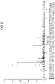
- Fig. 2 is an example of an X-ray diffraction chart of the inner peripheral surface of the gas passage pipe shown in Fig. 1
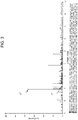
- Fig. 3 is an example of an X-ray diffraction chart of the outer peripheral surface of the gas passage pipe shown in Fig. 1 .
- the plasma processing apparatus 10 of the present disclosure shown in Fig. 1 is, for example, a plasma etching apparatus, and has a chamber 1 in which a member W to be processed such as a semiconductor wafer is arranged, an upper electrode 2 arranged on the upper side in the chamber 1, and a lower electrode 3 arranged opposed to each other on the lower side in the chamber 1.
- the upper electrode 2 contains an electrode plate 2b having a large number of gas passage pipes 2a for supplying the plasma generating gas G into the chamber 1, and a holding member 2e having a diffusion part 2c which is an internal space for diffusing the plasma generating gas G internally and a large number of introduction holes 2d for introducing the diffused plasma generating gas G into the gas passage pipes 2a.
- the plasma generating gas G discharged in the form of a shower from the gas passage pipes 2a becomes plasma by supplying high frequency power from the high frequency power supply 4, and then it forms a plasma space P.
- the electrode plate 2b and the gas passage pipes 2a may be collectively referred to as a shower plate 2f.
- the upper electrode 2, the lower electrode 3, and the highfrequency power supply 4 form a plasma generating apparatus.
- examples of the plasma generating gas G include fluorine-based gases such as SF 6 , CF 4 , CHF 3 , ClF 3 , NF 3 , C 4 F 8 , and HF, and chlorine-based gases such as Cl 2 , HCl, BCl 3 , and CCl 4 .
- the gas passage pipe 2a is an example of a member for a plasma processing apparatus. Hereinafter, it may be referred to as a member for a plasma processing apparatus 2a.
- the lower electrode 3 is, for example, a susceptor made of aluminum, and an electrostatic chuck 5 is placed on the susceptor and holds the member W to be processed by an electrostatic adsorption force.
- a coating film formed on the surface of the member W to be processed is etched by ions and radicals contained in plasma.
- the gas passage pipe 2a which is the member for the plasma processing apparatus 2a of the present disclosure, is made of, for example, a cylindrical ceramic sintered body containing yttrium oxide as a main component, and its inner peripheral surface and a discharge side end surface become surfaces exposed to the plasma generating gas G.
- the ceramic sintered body of the present disclosure contains yttrium oxide having a high corrosion resistance to the plasma generating gas G as a main component and contains yttrium silicate.
- Yttium silicate is less likely to be eroded than an amorphous part of the grain boundary phase, and when the ratio (I 1 /I 0 ) is 0.03 or more, the corrosion resistance to plasma is increased due to a reduction of particles generated from the grain boundary phase since the compressive stress on the amorphous part of the grain boundary phase and the crystal particles of yttrium oxide is applied.
- the ratio (I 1 /I 0 ) is 0.12 or less, the content of yttrium silicate having a larger linear expansion coefficient than yttrium oxide is suppressed in an appropriate range, so that cracks are less likely to occur even if heating and cooling are repeated.
- the ratio (I 1 /I 0 ) may be 0.04 or more and 0.1 or less.
- the ratio (I 1 /I 0 ) is 0.08
- the ratio (I 1 /I 0 ) is 0.04
- the composition formula of yttrium silicate is Y2SiO5 in both cases.
- the ceramic sintered body of the present disclosure may contain yttrium aluminum oxide which is at least one of YAP (AlYO 3 ), YAM (Al 2 Y 4 O 9 ) and YAG (Al 5 Y 3 O 12 ).
- these yttrium aluminum oxides are less likely to be eroded than an amorphous part of the grain boundary phase, and moreover the compressive stress on the amorphous part and the crystal particles of yttrium oxide is applied, particles generated from the grain boundary phase are reduced. Therefore, the ceramic sintered body satisfying the above constitution has even higher corrosion resistance.
- the presence of yttrium oxide, yttrium silicate and yttrium aluminum oxide can be confirmed by identifying it with an X-ray diffraction apparatus using CuK ⁇ rays.
- the content of each component can be determined by using, for example, the Rietveld method.
- the main component in the present disclosure refers to a component that accounts for 90% by mass or more of the total 100% by mass of all the components constituting the ceramic sintered body.
- the member for the plasma processing apparatus 2a of the present disclosure is made of the ceramic sintered body of the present disclosure, and its inside is a cylindrical body which serves as a flow path for the plasma generating gas G.
- the member for the plasma processing apparatus 2a of the present disclosure may contain a larger amount of yttrium silicate in the inner peripheral surface of the cylindrical body than the outer peripheral surface of the cylindrical body.
- the member for the plasma processing apparatus 2a of the present disclosure may contain a larger amount of yttrium aluminum oxide in the inner peripheral surface of the cylindrical body than the outer peripheral surface of the cylindrical body.
- the inner peripheral surface of the cylindrical body contains a larger amount of yttrium silicate or yttrium aluminum oxide than the outer surface of the cylindrical body, since the corrosion resistance of the inner peripheral surface directly exposed to the plasma generating gas G becomes higher than the outer peripheral surface exposed to the plasma generating gas G, it can be used for a long period of time.
- the maximum peak intensity I 0 on the inner peripheral surface of the cylindrical body may be larger than the maximum peak intensity I 0 on the outer peripheral surface of the cylindrical body.
- yttrium silicate contained in the inner peripheral surface of the cylindrical body has higher crystallinity than yttrium silicate contained in the outer peripheral surface of the cylindrical body, so that a higher compressive stress is applied to the amorphous part and crystal particles of yttrium oxide, and particles generated from the grain boundary phase is reduced.
- the ceramic sintered body of the present disclosure may contain, for example, at least one element of molybdenum, potassium, sodium, tungsten, and vanadium.
- a laser is irradiated onto the surface of the sintered ceramic body by using a laser ablation system. Then, the number of ion count of the elements evaporated from the surface can be detected by the ICP-MS method by using an ICP mass spectrometer.
- the ratio of the ion count of each element to yttrium is, for example, 0.1 to 0.6 for molybdenum, 0.01 to 0.1 for potassium, 0.01 to 0.1 for sodium, 0.01 to 0.1 for tungsten, and 0.01 to 0.1 for vanadium.
- the ceramic sintered body of the present disclosure is a cylindrical body
- the outer peripheral surface of the cylindrical body contains at least one of molybdenum, tungsten, and vanadium, which are refractory metals, more than the inner peripheral surface of the cylindrical body.
- Fig. 4(a) is an electron micrograph of the inner peripheral surface of the gas passage pipe shown in Fig. 1
- Fig. 4(b) is an electron micrograph of the outer peripheral surface of the gas passage pipe shown in Fig. 1 .
- the outer peripheral surface of the cylindrical body which is the gas passage pipe 2a may include a crystal particle 9 having a convex part 8 extending outward.
- the crystal particle 9 has a plurality of convex parts 8.
- yttrium oxide powder powder containing yttrium oxide having a purity of 99% as a main component
- a wax a wax, a dispersant and a plasticizer are prepared.
- the other component in the yttrium oxide powder is silicon dioxide.
- aluminum oxide may be further contained in the yttrium oxide powder.
- the wax is 13 parts by mass or more and 14 parts by mass or less
- the dispersant is 0.4 parts by mass or more and 0.5 parts by mass or less
- the plasticizer is 1.4 parts by mass or more and 1.5 parts by mass or less.
- the yttrium oxide powder, the wax, the dispersant, and the plasticizer all of which are heated to 100 °C or higher, are contained in a resin container.
- the wax, the dispersant, and the plasticizer are in liquid form.
- this container is set in a stirrer, and the container is rotated and revolved for 3 minutes (a rotating and revolving kneading process) to stir the yttrium oxide powder, the wax, the dispersant and the plasticizer to obtain a slurry.
- the obtained slurry is filled in a syringe, and the slurry is defoamed while rotating and revolving the syringe for 1 minute by using a defoaming tool.
- the syringe filled with the defoamed slurry is attached to an injection molding machine, and the slurry is injected into an inner space of a molding die while the temperature of the slurry is maintained at 90 °C or higher to obtain a cylindrical molded body.
- the flow path the slurry of the injection molding machine passes through may also be maintained at 90 °C or higher.
- the outer peripheral surface of the molded body is formed by the transfer of the inner peripheral surface of the molding die to be abutted and the sintering described later, a member for a plasma processing apparatus having a convex part of the crystal particle extending outward can be obtained by using a molding die having an inner peripheral surface including a concave part.
- a cylindrical sintered body can be obtained by sequentially degreasing and sintering the obtained molded product.
- the sintering atmosphere may be an air atmosphere
- the sintering temperature may be 1600 °C. or higher and 1800 °C or lower
- the holding time may be 2 hours or longer and 4 hours or less.
- At least the atmosphere surrounded by the inner peripheral surface of the cylindrical body may be controlled to have less number of floating impurities than the atmosphere outside this range.
- the member for the plasma processing apparatus 2a is arranged in the chamber 1 and is shown as the gas passage pipe 2a for generating stable plasma from the plasma generating gas G, but it may be a member that supplies the plasma generating gas G to the chamber 1, and a member that discharges the plasma generating gas G from the chamber 1.
Landscapes
- Engineering & Computer Science (AREA)
- Chemical & Material Sciences (AREA)
- Ceramic Engineering (AREA)
- Manufacturing & Machinery (AREA)
- Materials Engineering (AREA)
- Structural Engineering (AREA)
- Organic Chemistry (AREA)
- Physics & Mathematics (AREA)
- Plasma & Fusion (AREA)
- Analytical Chemistry (AREA)
- Inorganic Chemistry (AREA)
- Drying Of Semiconductors (AREA)
Abstract
Description
- This disclosure relates to a ceramic sintered body and a member for a plasma processing apparatus.
- Conventionally, in a process for manufacturing a semiconductor or a process for manufacturing a liquid crystal, plasma has been used in a film forming apparatus for forming a thin film on a substrate such as a semiconductor wafer or a glass substrate and an etching apparatus for performing a microfabrication on a substrate. In the film forming apparatus, a raw material gas is introduced into a chamber, and the raw material gas is used to excite atoms and molecules by plasma to form a thin film on a substrate. Further, in the etching apparatus, a halogen corrosive gas is introduced into a chamber as a raw material gas, and the raw material gas is converted into plasma and used as an etching gas to perform a microfabrication on a substrate.
- As a member exposed to such a plasma atmosphere, in
Patent Document 1, the applicant proposes a ceramic sintered body containing yttria (Y2O3) as a main component and at least one or more kind of Zr, Si, Ce or Al in an amount of 3 to 50,000 mass ppm as a sintering aid. - [Patent documents 1] Japanese Patent Unexamined Publication No.
2001-181042 - The ceramic sintered body of the present disclosure has yttrium oxide as a main component, contains yttrium silicate, and has a ratio (I1/I0) of a maximum peak intensity I1 of yttrium silicate having a diffraction angle 2θ of 30° to 32° with respect to a maximum intensity I0 of yttrium oxide having a diffraction angle 2θ of 28° to 30°, which is obtained by an X-ray diffraction method, is 0.03 or more and 0.12 or less.
- The member for the plasma processing apparatus of the present disclosure is made of the ceramic sintered body of the present disclosure, its inside is a cylindrical body which serves as a flow path for a plasma generating gas, and an inner peripheral surface of the cylindrical body contains a larger amount of yttrium silicate than an outer peripheral surface of the cylindrical body.
-
-
Fig. 1(a) is a cross sectional view showing a part of a plasma processing apparatus having an upper electrode equipped with gas passage pipes, which is a member for a plasma processing apparatus of the present disclosure, andFig. 1(b) is an enlarged view of the part A ofFig. 1(a) . -
Fig. 2 is an example of an X-ray diffraction chart of the inner peripheral surface of the gas passage pipe shown inFig. 1 . -
Fig. 3 is an example of an X-ray diffraction chart of the outer peripheral surface of the gas passage pipe shown inFig. 1 . -
Fig. 4(a) is an electron micrograph of the inner peripheral surface of the gas passage pipe shown inFIG. 1 , andFig. 4(b) is an electron micrograph of the outer peripheral surface of the gas passage pipe shown inFIG. 1 . - Hereinafter, the ceramic sintered body and the member for the plasma processing apparatus of the present disclosure are described below in detail with reference to the figures.
-
Fig. 1(a) is a cross-sectional view showing a part of the plasma processing apparatus having an upper electrode equipped with gas passage pipes, which is a member for a plasma processing apparatus of the present disclosure, andFig. 1(b) is an enlarged view of the part A ofFig. 1(a) . -
Fig. 2 is an example of an X-ray diffraction chart of the inner peripheral surface of the gas passage pipe shown inFig. 1 , andFig. 3 is an example of an X-ray diffraction chart of the outer peripheral surface of the gas passage pipe shown inFig. 1 . - The
plasma processing apparatus 10 of the present disclosure shown inFig. 1 is, for example, a plasma etching apparatus, and has achamber 1 in which a member W to be processed such as a semiconductor wafer is arranged, anupper electrode 2 arranged on the upper side in thechamber 1, and alower electrode 3 arranged opposed to each other on the lower side in thechamber 1. - The
upper electrode 2 contains anelectrode plate 2b having a large number ofgas passage pipes 2a for supplying the plasma generating gas G into thechamber 1, and aholding member 2e having a diffusion part 2c which is an internal space for diffusing the plasma generating gas G internally and a large number ofintroduction holes 2d for introducing the diffused plasma generating gas G into thegas passage pipes 2a. - Then, the plasma generating gas G discharged in the form of a shower from the
gas passage pipes 2a becomes plasma by supplying high frequency power from the highfrequency power supply 4, and then it forms a plasma space P. Theelectrode plate 2b and thegas passage pipes 2a may be collectively referred to as a shower plate 2f. - In
Fig. 1(a) , since thegas passage pipes 2a are small, only the positions are shown, and the detailed configuration is shown inFig. 1(b) . - Among these members, for example, the
upper electrode 2, thelower electrode 3, and thehighfrequency power supply 4 form a plasma generating apparatus. - Here, examples of the plasma generating gas G include fluorine-based gases such as SF6, CF4, CHF3, ClF3, NF3, C4F8, and HF, and chlorine-based gases such as Cl2, HCl, BCl3, and CCl4. The
gas passage pipe 2a is an example of a member for a plasma processing apparatus. Hereinafter, it may be referred to as a member for aplasma processing apparatus 2a. - The
lower electrode 3 is, for example, a susceptor made of aluminum, and anelectrostatic chuck 5 is placed on the susceptor and holds the member W to be processed by an electrostatic adsorption force. - Then, a coating film formed on the surface of the member W to be processed is etched by ions and radicals contained in plasma.
- The
gas passage pipe 2a, which is the member for theplasma processing apparatus 2a of the present disclosure, is made of, for example, a cylindrical ceramic sintered body containing yttrium oxide as a main component, and its inner peripheral surface and a discharge side end surface become surfaces exposed to the plasma generating gas G. - The ceramic sintered body of the present disclosure contains yttrium oxide having a high corrosion resistance to the plasma generating gas G as a main component and contains yttrium silicate. A ratio (I1/I0) of a maximum peak intensity I1 of yttrium silicate having a diffraction angle 2θ of 30° to 32° with respect to a maximum intensity I0 of yttrium oxide having a diffraction angle 2θ of 28° to 30°, which is obtained by an X-ray diffraction method, is 0.03 or more and 0.12 or less.
- Yttium silicate is less likely to be eroded than an amorphous part of the grain boundary phase, and when the ratio (I1/I0) is 0.03 or more, the corrosion resistance to plasma is increased due to a reduction of particles generated from the grain boundary phase since the compressive stress on the amorphous part of the grain boundary phase and the crystal particles of yttrium oxide is applied. On the contrary, when the ratio (I1/I0) is 0.12 or less, the content of yttrium silicate having a larger linear expansion coefficient than yttrium oxide is suppressed in an appropriate range, so that cracks are less likely to occur even if heating and cooling are repeated. The ratio (I1/I0) may be 0.04 or more and 0.1 or less.
- Here, in the X-ray diffraction chart shown in
Fig. 2 , the ratio (I1/I0) is 0.08, and in the X-ray diffraction chart shown inFig. 3 , the ratio (I1/I0) is 0.04, and the composition formula of yttrium silicate is Y2SiO5 in both cases. - Further, the ceramic sintered body of the present disclosure may contain yttrium aluminum oxide which is at least one of YAP (AlYO3), YAM (Al2Y4O9) and YAG (Al5Y3O12).
- Since these yttrium aluminum oxides are less likely to be eroded than an amorphous part of the grain boundary phase, and moreover the compressive stress on the amorphous part and the crystal particles of yttrium oxide is applied, particles generated from the grain boundary phase are reduced. Therefore, the ceramic sintered body satisfying the above constitution has even higher corrosion resistance.
- The presence of yttrium oxide, yttrium silicate and yttrium aluminum oxide can be confirmed by identifying it with an X-ray diffraction apparatus using CuKα rays. The content of each component can be determined by using, for example, the Rietveld method. Here, the main component in the present disclosure refers to a component that accounts for 90% by mass or more of the total 100% by mass of all the components constituting the ceramic sintered body.
- Further, the member for the
plasma processing apparatus 2a of the present disclosure is made of the ceramic sintered body of the present disclosure, and its inside is a cylindrical body which serves as a flow path for the plasma generating gas G. The member for theplasma processing apparatus 2a of the present disclosure may contain a larger amount of yttrium silicate in the inner peripheral surface of the cylindrical body than the outer peripheral surface of the cylindrical body. - Additionally, the member for the
plasma processing apparatus 2a of the present disclosure may contain a larger amount of yttrium aluminum oxide in the inner peripheral surface of the cylindrical body than the outer peripheral surface of the cylindrical body. - When the inner peripheral surface of the cylindrical body contains a larger amount of yttrium silicate or yttrium aluminum oxide than the outer surface of the cylindrical body, since the corrosion resistance of the inner peripheral surface directly exposed to the plasma generating gas G becomes higher than the outer peripheral surface exposed to the plasma generating gas G, it can be used for a long period of time.
- Further, in the member for the
plasma processing apparatus 2a of the present disclosure, the maximum peak intensity I0 on the inner peripheral surface of the cylindrical body may be larger than the maximum peak intensity I0 on the outer peripheral surface of the cylindrical body. - With such a constitution, yttrium silicate contained in the inner peripheral surface of the cylindrical body has higher crystallinity than yttrium silicate contained in the outer peripheral surface of the cylindrical body, so that a higher compressive stress is applied to the amorphous part and crystal particles of yttrium oxide, and particles generated from the grain boundary phase is reduced.
- In addition to yttrium oxide, the ceramic sintered body of the present disclosure may contain, for example, at least one element of molybdenum, potassium, sodium, tungsten, and vanadium.
- To confirm these elements, first, a laser is irradiated onto the surface of the sintered ceramic body by using a laser ablation system. Then, the number of ion count of the elements evaporated from the surface can be detected by the ICP-MS method by using an ICP mass spectrometer.
- In the ceramic sintered body of the present disclosure, when the number of ion count of yttrium is 100, the ratio of the ion count of each element to yttrium is, for example, 0.1 to 0.6 for molybdenum, 0.01 to 0.1 for potassium, 0.01 to 0.1 for sodium, 0.01 to 0.1 for tungsten, and 0.01 to 0.1 for vanadium.
- In particular, when the ceramic sintered body of the present disclosure is a cylindrical body, it is preferable that the outer peripheral surface of the cylindrical body contains at least one of molybdenum, tungsten, and vanadium, which are refractory metals, more than the inner peripheral surface of the cylindrical body.
-
Fig. 4(a) is an electron micrograph of the inner peripheral surface of the gas passage pipe shown inFig. 1 , andFig. 4(b) is an electron micrograph of the outer peripheral surface of the gas passage pipe shown inFig. 1 . - When the elements at
measurement points measurement point 6, and oxygen, yttrium, sodium and molybdenum are contained in themeasurement point 7. The content of molybdenum in a total of 100% by mass of the contents of oxygen, yttrium, sodium, and molybdenum is 1.6% by mass. - Further, the outer peripheral surface of the cylindrical body which is the
gas passage pipe 2a may include acrystal particle 9 having aconvex part 8 extending outward. - With
such crystal particle 9, when thegas passage pipe 2a is adhered to a member to be adhered such as theelectrode plate 2b, the anchor effect works within the surface of the exposed crystal particle, and thus the reliability of the adhered member is improved for a long period of time. - In the electron micrograph shown in
Fig. 4(b) , thecrystal particle 9 has a plurality ofconvex parts 8. - Next, an example of the method for manufacturing the ceramic sintered body of the present disclosure will be described.
- First, powder containing yttrium oxide having a purity of 99% as a main component (hereinafter referred to as yttrium oxide powder), a wax, a dispersant and a plasticizer are prepared. The other component in the yttrium oxide powder is silicon dioxide.
- Here, in the case of obtaining a ceramic sintered body containing yttrium aluminum oxide, aluminum oxide may be further contained in the yttrium oxide powder.
- With respect to 100 parts by mass of the yttrium oxide powder, the wax is 13 parts by mass or more and 14 parts by mass or less, the dispersant is 0.4 parts by mass or more and 0.5 parts by mass or less, and the plasticizer is 1.4 parts by mass or more and 1.5 parts by mass or less.
- Then, the yttrium oxide powder, the wax, the dispersant, and the plasticizer, all of which are heated to 100 °C or higher, are contained in a resin container. At this point, the wax, the dispersant, and the plasticizer are in liquid form. Next, this container is set in a stirrer, and the container is rotated and revolved for 3 minutes (a rotating and revolving kneading process) to stir the yttrium oxide powder, the wax, the dispersant and the plasticizer to obtain a slurry.
- Then, the obtained slurry is filled in a syringe, and the slurry is defoamed while rotating and revolving the syringe for 1 minute by using a defoaming tool.
- Next, the syringe filled with the defoamed slurry is attached to an injection molding machine, and the slurry is injected into an inner space of a molding die while the temperature of the slurry is maintained at 90 °C or higher to obtain a cylindrical molded body. Here, the flow path the slurry of the injection molding machine passes through may also be maintained at 90 °C or higher.
- Further, since the outer peripheral surface of the molded body is formed by the transfer of the inner peripheral surface of the molding die to be abutted and the sintering described later, a member for a plasma processing apparatus having a convex part of the crystal particle extending outward can be obtained by using a molding die having an inner peripheral surface including a concave part.
- A cylindrical sintered body can be obtained by sequentially degreasing and sintering the obtained molded product. Here, the sintering atmosphere may be an air atmosphere, the sintering temperature may be 1600 °C. or higher and 1800 °C or lower, and the holding time may be 2 hours or longer and 4 hours or less.
- To obtain a member for a plasma processing apparatus in which the maximum peak intensity I0 on the inner peripheral surface of the cylindrical body is larger than the maximum peak intensity I0 on the outer peripheral surface of the cylindrical body, at least the atmosphere surrounded by the inner peripheral surface of the cylindrical body may be controlled to have less number of floating impurities than the atmosphere outside this range.
- The present disclosure is not limited to the foregoing embodiment, and various changes, improvements, combinations, or the like can be made without departing from the scope of the present disclosure.
- In the example shown in
Fig. 1 , the member for theplasma processing apparatus 2a is arranged in thechamber 1 and is shown as thegas passage pipe 2a for generating stable plasma from the plasma generating gas G, but it may be a member that supplies the plasma generating gas G to thechamber 1, and a member that discharges the plasma generating gas G from thechamber 1. -
- 1: chamber
- 2: upper electrode
- 2a: member for plasma processing apparatus, gas passage pipe
- 2b: electrode plate
- 2c: diffusion part
- 2d: introduction hole
- 2e: holding member
- 2f: shower plate
- 3: lower electrode
- 4: high frequency power supply
- 5: electrostatic chuck
- 6, 7: measurement point
- 8: convex part
- 9: crystal particle
- 10: plasma processing apparatus
Claims (6)
- A ceramic sintered body comprising yttrium oxide as a main component, and containing yttrium silicate, wherein a ratio (I1/I0) of a maximum peak intensity I1 of yttrium silicate having a diffraction angle 2θ of 30° to 32° with respect to a maximum intensity I0 of yttrium oxide having a diffraction angle 2θ of 28° to 30°, obtained by an X-ray diffraction method, is 0.03 or more and 0.12 or less.
- The ceramic sintered body according to Claim 1, containing yttrium aluminum oxide which is at least one of YAP (AlYO3), YAM (Al2Y4O9) and YAG (Al5Y3O12).
- A member for a plasma processing apparatus comprising the ceramic sintered body according to Claim 1 or 2, and the inside being a cylindrical body which serves as a flow path for a plasma generating gas, wherein an inner peripheral surface of the cylindrical body contains a larger amount of yttrium silicate than an outer peripheral surface of the cylindrical body.
- The member for the plasma processing apparatus according Claim 3, wherein a maximum peak intensity I0 on the inner peripheral surface of the cylindrical body is larger than a maximum peak intensity I0 on the outer peripheral surface of the cylindrical body.
- The member for the plasma processing apparatus according to Claim 3 or 4, wherein the inner peripheral surface of the cylindrical body contains a larger amount of yttrium aluminum oxide than the outer peripheral surface of the cylindrical body.
- The member for the plasma processing apparatus according to any one of Claims 3 to 5, wherein the outer peripheral surface of the cylindrical body comprises a crystal particle having a convex part extending outward.
Applications Claiming Priority (2)
| Application Number | Priority Date | Filing Date | Title |
|---|---|---|---|
| JP2018123033 | 2018-06-28 | ||
| PCT/JP2019/025653 WO2020004563A1 (en) | 2018-06-28 | 2019-06-27 | Ceramic sintered body and member for plasma treatment device |
Publications (2)
| Publication Number | Publication Date |
|---|---|
| EP3816136A1 true EP3816136A1 (en) | 2021-05-05 |
| EP3816136A4 EP3816136A4 (en) | 2022-03-30 |
Family
ID=68986593
Family Applications (1)
| Application Number | Title | Priority Date | Filing Date |
|---|---|---|---|
| EP19824889.0A Withdrawn EP3816136A4 (en) | 2018-06-28 | 2019-06-27 | CERAMIC SINTERED BODY AND ELEMENT FOR PLASMA TREATMENT DEVICE |
Country Status (6)
| Country | Link |
|---|---|
| US (1) | US12165853B2 (en) |
| EP (1) | EP3816136A4 (en) |
| JP (1) | JP7112491B2 (en) |
| KR (1) | KR102585554B1 (en) |
| CN (1) | CN112334433B (en) |
| WO (1) | WO2020004563A1 (en) |
Families Citing this family (7)
| Publication number | Priority date | Publication date | Assignee | Title |
|---|---|---|---|---|
| WO2021060180A1 (en) * | 2019-09-27 | 2021-04-01 | 京セラ株式会社 | Part for plasma processing apparatus, manufacturing method thereof, and plasma processing apparatus |
| JP2023124888A (en) * | 2022-02-26 | 2023-09-07 | Toto株式会社 | Composite structures and semiconductor manufacturing equipment with composite structures |
| JP2023124889A (en) * | 2022-02-26 | 2023-09-07 | Toto株式会社 | Composite structures and semiconductor manufacturing equipment with composite structures |
| TW202334060A (en) * | 2022-02-26 | 2023-09-01 | 日商Toto股份有限公司 | Composite structure and semiconductor manufacturing device with composite structure |
| JP2023124887A (en) * | 2022-02-26 | 2023-09-07 | Toto株式会社 | Composite structures and semiconductor manufacturing equipment with composite structures |
| KR102659099B1 (en) * | 2022-09-06 | 2024-04-18 | 한국재료연구원 | Plasma etching device parts for semiconductor manufacturing including yttrium-based composite sintered body and manufacturing method thereof |
| CN119495541B (en) * | 2023-08-14 | 2026-03-17 | 中微半导体设备(上海)股份有限公司 | Plasma reaction devices, semiconductor components and their processing methods |
Family Cites Families (10)
| Publication number | Priority date | Publication date | Assignee | Title |
|---|---|---|---|---|
| JP3186158B2 (en) | 1992-01-21 | 2001-07-11 | 住友電気工業株式会社 | Composite ceramic sintered body and method for producing the same |
| US5459111A (en) * | 1992-01-21 | 1995-10-17 | Sumitomo Electric Industries, Ltd. | Composite ceramics sintered body |
| US6447937B1 (en) * | 1997-02-26 | 2002-09-10 | Kyocera Corporation | Ceramic materials resistant to halogen plasma and components using the same |
| JP4548887B2 (en) | 1999-12-27 | 2010-09-22 | 京セラ株式会社 | Corrosion-resistant ceramic member and manufacturing method thereof |
| JP2005097685A (en) * | 2002-11-27 | 2005-04-14 | Kyocera Corp | Corrosion resistant member and manufacturing method thereof |
| JP5134280B2 (en) | 2007-04-11 | 2013-01-30 | 株式会社ニッカトー | Y2O3 sintered body |
| JP5367522B2 (en) * | 2009-09-24 | 2013-12-11 | 東京エレクトロン株式会社 | Plasma processing apparatus and shower head |
| WO2013065666A1 (en) | 2011-10-31 | 2013-05-10 | 京セラ株式会社 | Gas nozzle, plasma device using same, and method for manufacturing gas nozzle |
| US10920318B2 (en) | 2015-10-30 | 2021-02-16 | Kyocera Corporation | Shower plate, semiconductor manufacturing apparatus, and method for manufacturing shower plate |
| EP3377318A1 (en) * | 2015-11-16 | 2018-09-26 | Coorstek Inc. | Corrosion-resistant components and methods of making |
-
2019
- 2019-06-27 WO PCT/JP2019/025653 patent/WO2020004563A1/en not_active Ceased
- 2019-06-27 CN CN201980041646.5A patent/CN112334433B/en not_active Expired - Fee Related
- 2019-06-27 EP EP19824889.0A patent/EP3816136A4/en not_active Withdrawn
- 2019-06-27 US US17/254,072 patent/US12165853B2/en active Active
- 2019-06-27 JP JP2020527643A patent/JP7112491B2/en not_active Expired - Fee Related
- 2019-06-27 KR KR1020207036882A patent/KR102585554B1/en active Active
Also Published As
| Publication number | Publication date |
|---|---|
| JPWO2020004563A1 (en) | 2021-08-02 |
| US20210265140A1 (en) | 2021-08-26 |
| JP7112491B2 (en) | 2022-08-03 |
| CN112334433B (en) | 2022-10-25 |
| KR102585554B1 (en) | 2023-10-06 |
| KR20210011442A (en) | 2021-02-01 |
| US12165853B2 (en) | 2024-12-10 |
| WO2020004563A1 (en) | 2020-01-02 |
| EP3816136A4 (en) | 2022-03-30 |
| CN112334433A (en) | 2021-02-05 |
Similar Documents
| Publication | Publication Date | Title |
|---|---|---|
| US12165853B2 (en) | Ceramic sintered body and member for plasma processing apparatus | |
| JP6046752B2 (en) | Gas nozzle and plasma apparatus using the same | |
| US20240059616A1 (en) | Plasma resistant yttrium aluminum oxide chamber components | |
| CN108352319B (en) | Shower plate, semiconductor manufacturing apparatus, and method for manufacturing shower plate | |
| JP7560478B2 (en) | Controlled Porous Yttrium Oxide for Etching Applications | |
| JP2008004926A (en) | Wafer holder, manufacturing method thereof, and semiconductor manufacturing apparatus | |
| KR102831967B1 (en) | Large-sized sintered yttrium oxide | |
| US20210387919A1 (en) | Ceramic tube | |
| JP6889268B2 (en) | Plasma processing equipment members and plasma processing equipment | |
| JP4570195B2 (en) | BORON CARBIDE BONDED BODY, ITS MANUFACTURING METHOD, AND PLASMA RESISTANT MEMBER | |
| JP5031259B2 (en) | Corrosion resistant member, method for manufacturing the same, and semiconductor / liquid crystal manufacturing apparatus using the same | |
| JP4623794B2 (en) | Alumina corrosion resistant member and plasma apparatus | |
| JP7129556B2 (en) | Corrosion resistant ceramics | |
| JP7329610B2 (en) | Member for plasma processing apparatus, manufacturing method thereof, and plasma processing apparatus | |
| JP3971539B2 (en) | Alumina plasma corrosion resistant material | |
| JP7470222B2 (en) | Gas nozzle manufacturing method | |
| US20220185740A1 (en) | Corrosion-resistant ceramic | |
| CN114762090A (en) | Plasma-resistant member, component for plasma processing apparatus, and plasma processing apparatus | |
| CN114664623A (en) | Plasma corrosion resistant semiconductor part and preparation method thereof and plasma reaction device |
Legal Events
| Date | Code | Title | Description |
|---|---|---|---|
| STAA | Information on the status of an ep patent application or granted ep patent |
Free format text: STATUS: THE INTERNATIONAL PUBLICATION HAS BEEN MADE |
|
| PUAI | Public reference made under article 153(3) epc to a published international application that has entered the european phase |
Free format text: ORIGINAL CODE: 0009012 |
|
| STAA | Information on the status of an ep patent application or granted ep patent |
Free format text: STATUS: REQUEST FOR EXAMINATION WAS MADE |
|
| 17P | Request for examination filed |
Effective date: 20201221 |
|
| AK | Designated contracting states |
Kind code of ref document: A1 Designated state(s): AL AT BE BG CH CY CZ DE DK EE ES FI FR GB GR HR HU IE IS IT LI LT LU LV MC MK MT NL NO PL PT RO RS SE SI SK SM TR |
|
| DAV | Request for validation of the european patent (deleted) | ||
| DAX | Request for extension of the european patent (deleted) | ||
| A4 | Supplementary search report drawn up and despatched |
Effective date: 20220225 |
|
| RIC1 | Information provided on ipc code assigned before grant |
Ipc: H01J 37/32 20060101ALI20220221BHEP Ipc: H01L 21/3065 20060101ALI20220221BHEP Ipc: C04B 35/44 20060101ALI20220221BHEP Ipc: C04B 35/505 20060101AFI20220221BHEP |
|
| P01 | Opt-out of the competence of the unified patent court (upc) registered |
Effective date: 20230505 |
|
| GRAP | Despatch of communication of intention to grant a patent |
Free format text: ORIGINAL CODE: EPIDOSNIGR1 |
|
| STAA | Information on the status of an ep patent application or granted ep patent |
Free format text: STATUS: GRANT OF PATENT IS INTENDED |
|
| INTG | Intention to grant announced |
Effective date: 20240521 |
|
| STAA | Information on the status of an ep patent application or granted ep patent |
Free format text: STATUS: THE APPLICATION IS DEEMED TO BE WITHDRAWN |
|
| 18D | Application deemed to be withdrawn |
Effective date: 20240924 |