EP3816004A1 - Vehicle collision detection method and vehicle control system - Google Patents
Vehicle collision detection method and vehicle control system Download PDFInfo
- Publication number
- EP3816004A1 EP3816004A1 EP19875143.0A EP19875143A EP3816004A1 EP 3816004 A1 EP3816004 A1 EP 3816004A1 EP 19875143 A EP19875143 A EP 19875143A EP 3816004 A1 EP3816004 A1 EP 3816004A1
- Authority
- EP
- European Patent Office
- Prior art keywords
- vehicle
- distance
- determining
- variance
- threshold
- Prior art date
- Legal status (The legal status is an assumption and is not a legal conclusion. Google has not performed a legal analysis and makes no representation as to the accuracy of the status listed.)
- Granted
Links
Images



Classifications
-
- B—PERFORMING OPERATIONS; TRANSPORTING
- B60—VEHICLES IN GENERAL
- B60W—CONJOINT CONTROL OF VEHICLE SUB-UNITS OF DIFFERENT TYPE OR DIFFERENT FUNCTION; CONTROL SYSTEMS SPECIALLY ADAPTED FOR HYBRID VEHICLES; ROAD VEHICLE DRIVE CONTROL SYSTEMS FOR PURPOSES NOT RELATED TO THE CONTROL OF A PARTICULAR SUB-UNIT
- B60W50/00—Details of control systems for road vehicle drive control not related to the control of a particular sub-unit, e.g. process diagnostic or vehicle driver interfaces
- B60W50/08—Interaction between the driver and the control system
- B60W50/14—Means for informing the driver, warning the driver or prompting a driver intervention
-
- B—PERFORMING OPERATIONS; TRANSPORTING
- B60—VEHICLES IN GENERAL
- B60W—CONJOINT CONTROL OF VEHICLE SUB-UNITS OF DIFFERENT TYPE OR DIFFERENT FUNCTION; CONTROL SYSTEMS SPECIALLY ADAPTED FOR HYBRID VEHICLES; ROAD VEHICLE DRIVE CONTROL SYSTEMS FOR PURPOSES NOT RELATED TO THE CONTROL OF A PARTICULAR SUB-UNIT
- B60W40/00—Estimation or calculation of non-directly measurable driving parameters for road vehicle drive control systems not related to the control of a particular sub unit, e.g. by using mathematical models
- B60W40/10—Estimation or calculation of non-directly measurable driving parameters for road vehicle drive control systems not related to the control of a particular sub unit, e.g. by using mathematical models related to vehicle motion
- B60W40/107—Longitudinal acceleration
-
- B—PERFORMING OPERATIONS; TRANSPORTING
- B60—VEHICLES IN GENERAL
- B60K—ARRANGEMENT OR MOUNTING OF PROPULSION UNITS OR OF TRANSMISSIONS IN VEHICLES; ARRANGEMENT OR MOUNTING OF PLURAL DIVERSE PRIME-MOVERS IN VEHICLES; AUXILIARY DRIVES FOR VEHICLES; INSTRUMENTATION OR DASHBOARDS FOR VEHICLES; ARRANGEMENTS IN CONNECTION WITH COOLING, AIR INTAKE, GAS EXHAUST OR FUEL SUPPLY OF PROPULSION UNITS IN VEHICLES
- B60K35/00—Instruments specially adapted for vehicles; Arrangement of instruments in or on vehicles
- B60K35/20—Output arrangements, i.e. from vehicle to user, associated with vehicle functions or specially adapted therefor
- B60K35/28—Output arrangements, i.e. from vehicle to user, associated with vehicle functions or specially adapted therefor characterised by the type of the output information, e.g. video entertainment or vehicle dynamics information; characterised by the purpose of the output information, e.g. for attracting the attention of the driver
-
- B—PERFORMING OPERATIONS; TRANSPORTING
- B60—VEHICLES IN GENERAL
- B60R—VEHICLES, VEHICLE FITTINGS, OR VEHICLE PARTS, NOT OTHERWISE PROVIDED FOR
- B60R21/00—Arrangements or fittings on vehicles for protecting or preventing injuries to occupants or pedestrians in case of accidents or other traffic risks
- B60R21/01—Electrical circuits for triggering passive safety arrangements, e.g. airbags, safety belt tighteners, in case of vehicle accidents or impending vehicle accidents
- B60R21/015—Electrical circuits for triggering passive safety arrangements, e.g. airbags, safety belt tighteners, in case of vehicle accidents or impending vehicle accidents including means for detecting the presence or position of passengers, passenger seats or child seats, and the related safety parameters therefor, e.g. speed or timing of airbag inflation in relation to occupant position or seat belt use
-
- B—PERFORMING OPERATIONS; TRANSPORTING
- B60—VEHICLES IN GENERAL
- B60W—CONJOINT CONTROL OF VEHICLE SUB-UNITS OF DIFFERENT TYPE OR DIFFERENT FUNCTION; CONTROL SYSTEMS SPECIALLY ADAPTED FOR HYBRID VEHICLES; ROAD VEHICLE DRIVE CONTROL SYSTEMS FOR PURPOSES NOT RELATED TO THE CONTROL OF A PARTICULAR SUB-UNIT
- B60W40/00—Estimation or calculation of non-directly measurable driving parameters for road vehicle drive control systems not related to the control of a particular sub unit, e.g. by using mathematical models
- B60W40/10—Estimation or calculation of non-directly measurable driving parameters for road vehicle drive control systems not related to the control of a particular sub unit, e.g. by using mathematical models related to vehicle motion
- B60W40/109—Lateral acceleration
-
- B—PERFORMING OPERATIONS; TRANSPORTING
- B62—LAND VEHICLES FOR TRAVELLING OTHERWISE THAN ON RAILS
- B62D—MOTOR VEHICLES; TRAILERS
- B62D41/00—Fittings for identifying vehicles in case of collision; Fittings for marking or recording collision areas
-
- B—PERFORMING OPERATIONS; TRANSPORTING
- B60—VEHICLES IN GENERAL
- B60K—ARRANGEMENT OR MOUNTING OF PROPULSION UNITS OR OF TRANSMISSIONS IN VEHICLES; ARRANGEMENT OR MOUNTING OF PLURAL DIVERSE PRIME-MOVERS IN VEHICLES; AUXILIARY DRIVES FOR VEHICLES; INSTRUMENTATION OR DASHBOARDS FOR VEHICLES; ARRANGEMENTS IN CONNECTION WITH COOLING, AIR INTAKE, GAS EXHAUST OR FUEL SUPPLY OF PROPULSION UNITS IN VEHICLES
- B60K2360/00—Indexing scheme associated with groups B60K35/00 or B60K37/00 relating to details of instruments or dashboards
- B60K2360/16—Type of output information
- B60K2360/176—Camera images
-
- B—PERFORMING OPERATIONS; TRANSPORTING
- B60—VEHICLES IN GENERAL
- B60W—CONJOINT CONTROL OF VEHICLE SUB-UNITS OF DIFFERENT TYPE OR DIFFERENT FUNCTION; CONTROL SYSTEMS SPECIALLY ADAPTED FOR HYBRID VEHICLES; ROAD VEHICLE DRIVE CONTROL SYSTEMS FOR PURPOSES NOT RELATED TO THE CONTROL OF A PARTICULAR SUB-UNIT
- B60W30/00—Purposes of road vehicle drive control systems not related to the control of a particular sub-unit, e.g. of systems using conjoint control of vehicle sub-units
- B60W30/08—Active safety systems predicting or avoiding probable or impending collision or attempting to minimise its consequences
- B60W2030/082—Vehicle operation after collision
-
- B—PERFORMING OPERATIONS; TRANSPORTING
- B60—VEHICLES IN GENERAL
- B60W—CONJOINT CONTROL OF VEHICLE SUB-UNITS OF DIFFERENT TYPE OR DIFFERENT FUNCTION; CONTROL SYSTEMS SPECIALLY ADAPTED FOR HYBRID VEHICLES; ROAD VEHICLE DRIVE CONTROL SYSTEMS FOR PURPOSES NOT RELATED TO THE CONTROL OF A PARTICULAR SUB-UNIT
- B60W50/00—Details of control systems for road vehicle drive control not related to the control of a particular sub-unit, e.g. process diagnostic or vehicle driver interfaces
- B60W2050/0001—Details of the control system
- B60W2050/0002—Automatic control, details of type of controller or control system architecture
- B60W2050/0008—Feedback, closed loop systems or details of feedback error signal
- B60W2050/001—Proportional integral [PI] controller
-
- B—PERFORMING OPERATIONS; TRANSPORTING
- B60—VEHICLES IN GENERAL
- B60W—CONJOINT CONTROL OF VEHICLE SUB-UNITS OF DIFFERENT TYPE OR DIFFERENT FUNCTION; CONTROL SYSTEMS SPECIALLY ADAPTED FOR HYBRID VEHICLES; ROAD VEHICLE DRIVE CONTROL SYSTEMS FOR PURPOSES NOT RELATED TO THE CONTROL OF A PARTICULAR SUB-UNIT
- B60W50/00—Details of control systems for road vehicle drive control not related to the control of a particular sub-unit, e.g. process diagnostic or vehicle driver interfaces
- B60W2050/0001—Details of the control system
- B60W2050/0019—Control system elements or transfer functions
- B60W2050/002—Integrating means
-
- B—PERFORMING OPERATIONS; TRANSPORTING
- B60—VEHICLES IN GENERAL
- B60W—CONJOINT CONTROL OF VEHICLE SUB-UNITS OF DIFFERENT TYPE OR DIFFERENT FUNCTION; CONTROL SYSTEMS SPECIALLY ADAPTED FOR HYBRID VEHICLES; ROAD VEHICLE DRIVE CONTROL SYSTEMS FOR PURPOSES NOT RELATED TO THE CONTROL OF A PARTICULAR SUB-UNIT
- B60W50/00—Details of control systems for road vehicle drive control not related to the control of a particular sub-unit, e.g. process diagnostic or vehicle driver interfaces
- B60W50/08—Interaction between the driver and the control system
- B60W50/14—Means for informing the driver, warning the driver or prompting a driver intervention
- B60W2050/143—Alarm means
-
- B—PERFORMING OPERATIONS; TRANSPORTING
- B60—VEHICLES IN GENERAL
- B60W—CONJOINT CONTROL OF VEHICLE SUB-UNITS OF DIFFERENT TYPE OR DIFFERENT FUNCTION; CONTROL SYSTEMS SPECIALLY ADAPTED FOR HYBRID VEHICLES; ROAD VEHICLE DRIVE CONTROL SYSTEMS FOR PURPOSES NOT RELATED TO THE CONTROL OF A PARTICULAR SUB-UNIT
- B60W50/00—Details of control systems for road vehicle drive control not related to the control of a particular sub-unit, e.g. process diagnostic or vehicle driver interfaces
- B60W50/08—Interaction between the driver and the control system
- B60W50/14—Means for informing the driver, warning the driver or prompting a driver intervention
- B60W2050/146—Display means
-
- B—PERFORMING OPERATIONS; TRANSPORTING
- B60—VEHICLES IN GENERAL
- B60W—CONJOINT CONTROL OF VEHICLE SUB-UNITS OF DIFFERENT TYPE OR DIFFERENT FUNCTION; CONTROL SYSTEMS SPECIALLY ADAPTED FOR HYBRID VEHICLES; ROAD VEHICLE DRIVE CONTROL SYSTEMS FOR PURPOSES NOT RELATED TO THE CONTROL OF A PARTICULAR SUB-UNIT
- B60W2420/00—Indexing codes relating to the type of sensors based on the principle of their operation
- B60W2420/40—Photo, light or radio wave sensitive means, e.g. infrared sensors
- B60W2420/403—Image sensing, e.g. optical camera
-
- B—PERFORMING OPERATIONS; TRANSPORTING
- B60—VEHICLES IN GENERAL
- B60W—CONJOINT CONTROL OF VEHICLE SUB-UNITS OF DIFFERENT TYPE OR DIFFERENT FUNCTION; CONTROL SYSTEMS SPECIALLY ADAPTED FOR HYBRID VEHICLES; ROAD VEHICLE DRIVE CONTROL SYSTEMS FOR PURPOSES NOT RELATED TO THE CONTROL OF A PARTICULAR SUB-UNIT
- B60W2420/00—Indexing codes relating to the type of sensors based on the principle of their operation
- B60W2420/54—Audio sensitive means, e.g. ultrasound
-
- B—PERFORMING OPERATIONS; TRANSPORTING
- B60—VEHICLES IN GENERAL
- B60W—CONJOINT CONTROL OF VEHICLE SUB-UNITS OF DIFFERENT TYPE OR DIFFERENT FUNCTION; CONTROL SYSTEMS SPECIALLY ADAPTED FOR HYBRID VEHICLES; ROAD VEHICLE DRIVE CONTROL SYSTEMS FOR PURPOSES NOT RELATED TO THE CONTROL OF A PARTICULAR SUB-UNIT
- B60W2520/00—Input parameters relating to overall vehicle dynamics
- B60W2520/10—Longitudinal speed
- B60W2520/105—Longitudinal acceleration
-
- B—PERFORMING OPERATIONS; TRANSPORTING
- B60—VEHICLES IN GENERAL
- B60W—CONJOINT CONTROL OF VEHICLE SUB-UNITS OF DIFFERENT TYPE OR DIFFERENT FUNCTION; CONTROL SYSTEMS SPECIALLY ADAPTED FOR HYBRID VEHICLES; ROAD VEHICLE DRIVE CONTROL SYSTEMS FOR PURPOSES NOT RELATED TO THE CONTROL OF A PARTICULAR SUB-UNIT
- B60W2520/00—Input parameters relating to overall vehicle dynamics
- B60W2520/12—Lateral speed
- B60W2520/125—Lateral acceleration
-
- B—PERFORMING OPERATIONS; TRANSPORTING
- B60—VEHICLES IN GENERAL
- B60W—CONJOINT CONTROL OF VEHICLE SUB-UNITS OF DIFFERENT TYPE OR DIFFERENT FUNCTION; CONTROL SYSTEMS SPECIALLY ADAPTED FOR HYBRID VEHICLES; ROAD VEHICLE DRIVE CONTROL SYSTEMS FOR PURPOSES NOT RELATED TO THE CONTROL OF A PARTICULAR SUB-UNIT
- B60W2540/00—Input parameters relating to occupants
- B60W2540/215—Selection or confirmation of options
-
- B—PERFORMING OPERATIONS; TRANSPORTING
- B60—VEHICLES IN GENERAL
- B60W—CONJOINT CONTROL OF VEHICLE SUB-UNITS OF DIFFERENT TYPE OR DIFFERENT FUNCTION; CONTROL SYSTEMS SPECIALLY ADAPTED FOR HYBRID VEHICLES; ROAD VEHICLE DRIVE CONTROL SYSTEMS FOR PURPOSES NOT RELATED TO THE CONTROL OF A PARTICULAR SUB-UNIT
- B60W2554/00—Input parameters relating to objects
-
- B—PERFORMING OPERATIONS; TRANSPORTING
- B60—VEHICLES IN GENERAL
- B60W—CONJOINT CONTROL OF VEHICLE SUB-UNITS OF DIFFERENT TYPE OR DIFFERENT FUNCTION; CONTROL SYSTEMS SPECIALLY ADAPTED FOR HYBRID VEHICLES; ROAD VEHICLE DRIVE CONTROL SYSTEMS FOR PURPOSES NOT RELATED TO THE CONTROL OF A PARTICULAR SUB-UNIT
- B60W2554/00—Input parameters relating to objects
- B60W2554/80—Spatial relation or speed relative to objects
- B60W2554/801—Lateral distance
-
- B—PERFORMING OPERATIONS; TRANSPORTING
- B60—VEHICLES IN GENERAL
- B60W—CONJOINT CONTROL OF VEHICLE SUB-UNITS OF DIFFERENT TYPE OR DIFFERENT FUNCTION; CONTROL SYSTEMS SPECIALLY ADAPTED FOR HYBRID VEHICLES; ROAD VEHICLE DRIVE CONTROL SYSTEMS FOR PURPOSES NOT RELATED TO THE CONTROL OF A PARTICULAR SUB-UNIT
- B60W2554/00—Input parameters relating to objects
- B60W2554/80—Spatial relation or speed relative to objects
- B60W2554/802—Longitudinal distance
Definitions
- the present disclosure relates to the field of vehicle technologies, and more particularly, to a vehicle collision detection method and a vehicle control system.
- some cars can automatically detect collision accidents and perform corresponding control operations (such as popping out airbags) after detecting collision accidents.
- Conventional collision detection methods generally utilize angular velocities and accelerations of the vehicle in a three-dimensional space detected by an Inertial Measurement Unit (IMU) of the vehicle.
- IMU Inertial Measurement Unit
- Embodiments of the disclosure provide a vehicle collision detection method and a vehicle control system, which can reduce misjudgments and improve the accuracy of vehicle collision detection.
- inventions of the disclosure provide a vehicle collision detection method.
- the method includes:
- the method further includes:
- the method further includes:
- detecting the distance between the vehicle and the obstacle includes:
- the method further includes: taking the distance data as the relative distance between the vehicle and the obstacle.
- embodiments of the disclosure provide a vehicle control system, the vehicle control system includes :
- the acquiring unit is further configured to acquire an acceleration component of the vehicle in a vertical direction within the first specified time period, when the determining unit determines that the relative distance is less than the distance threshold.
- the variance determining unit is further configured to determine a third variance of the vertical acceleration component.
- the vehicle control system further includes:
- the vehicle control system further includes:
- the first determining unit includes:
- the distance determining subunit is further configured to take the distance data as the relative distance between the vehicle and the obstacle, when the second determining subunit determines that the distance data is greater than the lower limit
- embodiments of the disclosure provide a vehicle control system, the vehicle control system includes:
- the processor is configured to perform any of the methods of the first aspect of the embodiment of the disclosure by invoking the executable program codes stored in the memory.
- embodiments of the disclosure provide a computer-readable storage medium storing a computer program that causes a computer to execute any method disclosed in the first aspect of the embodiment of the disclosure.
- embodiments of the disclosure provide a computer program product, which runs on a computer to enable the computer to execute any method disclosed in the first aspect of the embodiment of the disclosure.
- the disclosure has the following beneficial effects:
- conventional vehicle collision detection method usually takes a sudden change of acceleration as a collision accident happens to the vehicle.
- a sudden braking is an active deceleration behavior of the vehicle, such a sudden deceleration behavior also causes a sudden change of acceleration, so the sudden braking is easily misjudged as a collision accident.
- the relative distance between the vehicle and the obstacle is detected, and after determining that the relative distance is less than the distance threshold, then the vehicle is detected, according to obtained acceleration information, whether a collision accident happens. Specifically, the disclosure determines whether a collision accident happens to the vehicle by judging the variance of the acceleration of the vehicle in a horizontal direction (i.e., the longitudinal and lateral directions).
- the disclosure can reduce misjudgments and improve the accuracy of vehicle collision detection.
- Embodiments of the disclosure provide a vehicle collision detection method and a vehicle control system, which can improve the accuracy of vehicle collision detection. Details are described below.
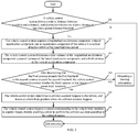
- FIG. 1 is a schematic flowchart of a vehicle collision detection method according to an embodiment of the disclosure. As illustrated in FIG. 1 , the vehicle collision detection method may include the following steps.
- a vehicle control system detects a relative distance between a vehicle and an obstacle.
- the vehicle control system may detect the relative distance between the vehicle and the obstacle by using measurement data detected by a distance measuring sensor and/or a camera.
- the distance measuring sensor may be an ultrasonic distance measuring sensor, a laser distance measuring sensor, an infrared distance measuring sensor, a microwave distance measuring sensor, and so on, which are not limited by the embodiment of the disclosure.
- the vehicle control system detects the relative distance between the vehicle and the obstacle by the distance measuring sensor, it can directly read the distance data fed back by the distance measuring sensor, and take the distance data as a first distance between the vehicle and the obstacle.
- the distance measuring sensor has a distance measuring range.
- the vehicle control system determines whether the distance between the vehicle and the obstacle is too close based on the distance data fed back by the distance measurement sensor, so it is necessary to consider a lower limit of the distance measuring range.
- the vehicle control system can determine whether the distance data is the lower limit of the distance measuring range of the distance measuring sensor.
- the vehicle control system acquires acceleration information of the vehicle to calculate an estimated moving distance of the vehicle within a period of time, so as to accurately determine the relative distance between the vehicle and the obstacle according to the distance data fed back by the distance measuring sensor and the estimated moving distance.
- the vehicle control system determines whether the relative distance is less than a preset distance threshold. And if yes, the step 103 is performed, if not, the procedure is ended.
- the preset distance threshold may be set by a user. Specifically, the preset distance threshold can be set to a smaller value.
- the preset distance threshold can be set to a smaller value.
- the relative distance between the vehicle and the obstacle is less than the preset distance threshold, it can be considered that a collision between the vehicle and the obstacle will happen. Since the sudden braking is an emergency braking behavior actively carried out by the driver, the vehicle is relatively far away from the obstacle at this time. Therefore, according to the determination of the relative distance, the probability of misjudging the sudden braking as a collision accident can be reduced.
- a vehicle speed can further be a pre-detection condition.
- the step 103 After determining that the relative distance between the vehicle and the obstacle is less than the distance threshold, and before performing the following step 103, it can be determined whether the vehicle speed exceeds a certain speed threshold. And if yes, the step 103 is continuously performed. Thus, the acceleration information of the vehicle can be acquired when the relative distance between the vehicle and the obstacle is less than the distance threshold and the vehicle speed exceeds the speed threshold.
- the vehicle control system acquires a longitudinal acceleration component and a lateral acceleration component of the vehicle within a first specified time period.
- the acceleration variation is small (for example, the acceleration variation is less than 5g).
- the acceleration variation is less than 5g.
- the acceleration components in various directions may be measured by the accelerometer of the vehicle.
- the first specified time period can be set, for example, the first specified time period can be Is.
- the measurement frequency of the accelerometer is relatively high.
- the accelerometer can respectively measure a set of acceleration component data in each direction.
- the vehicle control system determines a first variance of the longitudinal acceleration component and a second variance of the lateral acceleration component.
- the variance is a parameter relative to the dispersion degree of a set of data, it can be determined whether the acceleration has a sudden change by calculating the variance of the acceleration component.
- ⁇ 2 is a variance of the acceleration component in a direction
- X is a group of the acceleration components in the direction
- ⁇ is an average value of the acceleration components in the direction within the first specified time period
- N is the number of the acceleration components obtained in the direction.
- the vehicle control system determines a collision accident happens to the vehicle, when the first variance exceeds a preset first threshold or the second variance exceeds a preset second threshold.
- the first threshold is determined according to a variance of the longitudinal acceleration component of the vehicle in a normal running process
- the second threshold is determined according to the variance of the lateral acceleration component of the vehicle in a normal running process.
- FIG. 2 is a schematic flowchart of another vehicle collision detection method according to the embodiment of the disclosure. As illustrated in FIG. 2 , the vehicle collision detection method may include the following steps.
- a vehicle control system detects a relative distance between a vehicle and an obstacle, and determines whether the relative distance is less than a preset distance threshold. And if yes, step 202 is performed, if not, the procedure is ended.
- the vehicle control system acquires a longitudinal acceleration component, a lateral acceleration component, and an acceleration component of the vehicle in a vertical direction within a first specified time period.
- the acceleration components can be acquired from measurement data of a tri-axis accelerometer of the vehicle.
- the tri-axis accelerometer can acquire the acceleration components of the vehicle in X-axis (longitudinal direction), Y-axis (lateral direction), and Z-axis(vertical direction) centered on the vehicle.
- the vehicle control system determines a first variance of the longitudinal acceleration component, a second variance of the lateral acceleration component, and a third variance of the vertical acceleration component.
- the vehicle control system determines whether the third variance is less than a preset third threshold, and if yes, the step 205 to 206 are performed, if not, a warning information is output.
- the accuracy of collision detection can be further improved by determining the variance of the acceleration component in the vertical direction.
- a sudden change of the acceleration component in a horizontal direction of the vehicle is caused by the collision.
- acceleration component in the horizontal direction may also change suddenly when the vehicle is running through a speed bump or an uneven road.
- the embodiment of the disclosure introduces the judgment of the acceleration component in the vertical direction of the vehicle. When the vehicle is running though the speed bump or the uneven road, the vehicle body may bump up and down, and the acceleration component in the vertical direction will greatly change.
- the third threshold can be determined according to the variance of acceleration component in the vertical direction in a normal running process of the vehicle.
- the warning information can be output to notify the driver to confirm whether the collision has happened.
- the vehicle control system determines a collision accident happens to the vehicle, and detects a vehicle body position where the collision accident happens.
- the vehicle control system can determine the vehicle body position where the collision accident happens by detecting an installation position of the distance measuring sensor that detects the obstacle close to the vehicle. For example, if an ultrasonic distance sensor installed on the left side of the front of the vehicle (based on a running direction of the vehicle) detects the obstacle whose relative distance to the vehicle is less than the distance threshold, and it is determined that the collision accident has happened to the vehicle by performing the above steps 202 to 204, it can be determined that the collision accident has happened on the left side of the front of the vehicle.
- the vehicle control system triggers a camera corresponding to the vehicle body position to capture images, thereby enabling a driver to confirm the collision accident according to the captured images.
- the camera corresponding to the vehicle body position where the collision accident happens has a view range including the vehicle body position where the collision accident happens.
- an installation position of the camera can be different with the vehicle body position where the collision accident happens.
- the vehicle control system detects the collision accident on the left side of the front of the vehicle, by controlling a driving mirror installed on the left side of the vehicle, the camera can face the left side of the front of the vehicle to capture images.
- the vehicle control system can output the image captured by the camera to a display screen inside the vehicle to display, thereby enabling the driver of the vehicle can use the captured image to confirm the collision accident.
- the captured images can also be sent to a terminal which is bound with the vehicle in advance, so that the terminal can store the captured images as a certification for the confirmation.
- FIG. 3 is still another vehicle collision detection method according to an embodiment of the disclosure. As illustrated in FIG. 3 , the vehicle collision detection method may include the following steps.
- a vehicle control system determines whether distance data fed back by a distance measuring sensor of the vehicle is equal to a lower limit of a distance measuring range of the distance measuring sensor. And if yes, step 302 to 303 are performed, if not and a first distance is greater than the lower limit of the distance measuring range, step 304 is performed.
- an ultrasonic distance measuring sensor is used.
- the lower limit of the distance measuring range of the ultrasonic sensor can be 26 cm (according to the different performance of the ultrasonic sensor, the value of the lower limit of the distance measuring range can be different).
- the distance data fed by the ultrasonic sensor will always be 26cm. Therefore, when the distance data fed back by the ultrasonic distance measuring sensor is 26 cm, it can be considered that the distance data is unreliable.
- the vehicle control system After receiving the distance data fed back by the distance measuring sensor, the vehicle control system performing the following steps 302 to 304 instead of directly taking the distance data as the distance between the vehicle and the obstacle.
- the vehicle control system acquires acceleration information of the vehicle at the current moment, and uses the acceleration information to determine an estimated moving distance of the vehicle within a second specified time period.
- the second specified time period can be a relatively short time.
- it can be a reaction time of a driver (i.e., 0.3s to 1.0s).
- the acceleration information is used to integrate the second specified time period in time, thereby calculating the estimated moving distance of the vehicle after the specified time period.
- L ⁇ ⁇ ⁇ a ⁇ dt dt ;
- L is the estimated moving distance of the vehicle in the specified time period
- (a) is the acceleration information
- t is the time.
- the vehicle control system determines, according to the distance data fed back by the distance measuring sensor and the estimated moving distance, a relative distance between the vehicle and the obstacle.
- the vehicle control system can determine the relative distance between the vehicle and the obstacle according to the distance data fed back by the distance measuring sensor and the estimated moving distance.
- the difference between the distance data and the estimated moving distance can be taken as the relative distance between the vehicle and the obstacle.
- the relative distance between the vehicle and the obstacle will gradually be decreased, and also, the distance data fed by the distance measuring sensor will gradually be decreased.
- the acceleration data of the vehicle is used to estimate the estimated moving distance of the vehicle at the next moment (i.e., the second specified time period). According to the distance data fed by the ultrasonic sensors and the estimated moving distance, a relative distance between the vehicle and the obstacle at the next moment can be accurately determined.
- the acceleration data can be used to calculate the relative distance between the vehicle and the obstacle, and the measurement accuracy of the ultrasonic distance measuring sensor can be improved without rebuilding hardware.
- the vehicle control system takes the distance data as the relative distance between the vehicle and the obstacle.
- the distance data fed back by the ultrasonic distance measuring sensor when the distance data fed back by the ultrasonic distance measuring sensor is not the lower limit of the distance measuring range, especially when the distance data is greater than the lower limit of the distance measuring range, the distance data can be considered reliable.
- the distance data fed back by the ultrasonic distance measuring sensor can be directly taken as the relative distance between the vehicle and the obstacle so as to reduce calculation load.
- the vehicle control system determines whether the relative distance is less than a preset distance threshold, and if yes, step 306 is performed, and if not, the procedure is ended.
- the steps 306 to 310 in the present embodiment of the disclosure are similar to the steps 202 to 206 in the embodiment 2, and are not described here.
- the collision accident of the vehicle when determining the vehicle is close to the obstacle, the collision accident of the vehicle can be determined by analyzing the acceleration information of the vehicle. Further, the collision accident of the vehicle can be confirmed according to the images captured by the camera.
- the distance sensor can be used to detect the distance between the vehicle and the obstacle.
- the acceleration data of the vehicle can be used to calculate the estimated moving distance of the vehicle at the specified time period.
- the relative distance between the vehicle and the obstacle at the next moment can be accurately determined according to the distance data.
- the measurement accuracy of the ultrasonic distance measuring sensor can be increased without rebuilding hardware.
- the distance data fed by the ultrasonic sensor is not the lower limit of the distance measuring range, the distance data fed back by the distance measuring sensor can be taken as the relative distance between the vehicle and the obstacle, thereby reducing calculation load.
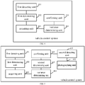
- FIG. 4 is a schematic block diagram of a vehicle control system according to an embodiment of the disclosure.
- the vehicle control system may include a first detecting unit 401, a first determining unit 402, an acquiring unit 403, a variance determining unit 404 and a confirming unit 405.
- the first detecting unit 401 is configured to detect a relative distance between a vehicle and an obstacle.
- the first determining unit 402 is configured to determine whether the relative distance by the first detecting unit 401 is less than a preset distance threshold.
- the preset distance threshold can be set by a user.
- the preset distance threshold can be a smaller value. When the relative distance between the vehicle and the obstacle is less than the distance threshold, it can be considered that a collision between the vehicle and the obstacle there will happen.
- the acquiring unit 403 is configured to acquire a longitudinal acceleration component and a lateral acceleration component of the vehicle within a first specified time period, when the determining unit 402 determining that the relative distance is less than a preset distance threshold.
- the variance determining unit 404 is configured to determine a first variance of the longitudinal acceleration component acquired by the acquiring unit 403 and a second variance of the lateral acceleration component acquired by the acquiring unit 403;
- the confirming unit 405, is configured to determine that a collision accident happens to the vehicle, when the variance determining unit 404 determines that the first variance exceeds a preset first threshold or that the second variance exceeds a preset second threshold.
- the following steps can also be performed.
- the acquisition unit 403 is triggered to perform the step of acquiring the acceleration information of the vehicle corresponding to the relative distance less than the distance threshold.
- the distance and the vehicle speed can be a dual judgment.
- the acquiring unit 403 can acquire the acceleration information of the vehicle when the relative distance between the vehicle and the obstacle is less than the distance threshold and the vehicle speed exceeds the speed threshold, thereby further increasing the accuracy of detecting the collision.
- the vehicle control system illustrated in FIG. 4 can confirm the collision of the vehicle according to the acceleration information of the vehicle (i.e., the variance of the acceleration component in the horizontal direction), when it is determined that the relative distance between the vehicle and the obstacle is less than the distance threshold. Therefore, the probability of misjudging the emergency brake as a collision accident can be reduced and the accuracy of detecting the collision can be increased.
- the acceleration information of the vehicle i.e., the variance of the acceleration component in the horizontal direction
- FIG. 5 is a schematic block diagram of another vehicle control system according to an embodiment of the disclosure.
- the vehicle control system illustrated in FIG. 5 is obtained by optimizing the vehicle control system illustrated in FIG. 4 .
- the vehicle control system illustrated in Figure 5 is the vehicle control system illustrated in Figure 5 .
- the acquiring unit 403 is further configured to acquire an acceleration component of the vehicle in a vertical direction within the first specified time period, when the first determining unit 402 determines that the relative distance is less than the distance threshold.
- the variance determining unit 404 is further configured to determine a third variance of the vertical acceleration component.
- the vehicle control system illustrated in FIG. 5 further includes a second determining unit 407.
- the second determining unit 407 is configured to determine whether the third variance determined by the variance determining unit 404 is less than a preset third threshold.
- the confirming unit 405 is configured to determine a collision accident happening to the vehicle, when the first variance exceeds the first threshold or the second variance exceeds the second threshold, and when the second determining unit 407 determines that the third variance is less than the third threshold.
- the confirming unit 404 may determine the sudden change of the acceleration of the vehicle according to the variance of the acceleration component of the vehicle, thereby confirming a collision accident happening to the vehicle according to the sudden change of acceleration.
- the vehicle control system illustrated in FIG. 5 can further detect the variance of the acceleration component in the vertical direction, thereby reducing the impact of detecting the collision of the vehicle running on the speed bump or the uneven road, and further increasing the accuracy of detecting the collision.
- the vehicle control system illustrated in FIG. 5 may further includes a second detecting unit 405 and a photographing unit 406.
- the second detecting unit 405 is configured to detect a vehicle body position where the collision accident happens, after the confirming unit 404 determines the collision accident happening to the vehicle.
- the second detecting unit 405 may determine the vehicle body position where the collision accident happens by detecting an installation position of the sensor detecting the detected obstacle.
- the photographing unit 406 is configured to trigger a camera corresponding to the vehicle body position detected by the confirming unit 405 to capture images, thereby enabling a driver to confirm the collision accident according to the captured images.
- the photographing unit 406 can send the images to a display screen inside the vehicle to display, thereby enabling the driver can use the captured images to confirm the collision accident.
- the photographing unit 406 can also send the image to the terminal which is bound with the vehicle in advance, so that the terminal can store the images as a certification for the confirmation.
- the vehicle control system illustrated in Figure 5 when determining the relative distance between the vehicle and the obstacle is relatively small, the vehicle control system determines a sudden change of the acceleration by calculating the variance of the acceleration component, thereby determining that the collision accident happens to the vehicle.
- the vehicle control system illustrated in Figure 5 can also trigger the corresponding camera to capture the images after determining the collision accident, thereby enabling the driver to confirm the collision accident according to the captured images.
- the purpose of further verifying and preserving evidence of the accident evidence can be achieved.
- FIG. 6 is a schematic block diagram of still another vehicle control system according to an embodiment of the disclosure.
- the vehicle control system illustrated in FIG. 6 is obtained by optimizing the vehicle control system illustrated in FIG. 5 .
- the first detecting unit 401 may include a determining subunit 4011, an acquiring subunit 4012, a displacement determining subunit 4013 and distance determining subunit 4014.
- the determining subunit 4011 is configured to determine whether a distance data fed back by a distance measuring sensor of the vehicle is equal to a lower limit of a distance measuring range of the distance measuring sensor.
- the acquiring subunit 4012 is configured to acquire acceleration information of the vehicle at the current moment, when the determining subunit 4011 determines that the distance data is the lower limit.
- the displacement determining subunit 4013 is configured to use the acceleration information acquired by the acquiring subunit 4012 to determine an estimated moving distance of the vehicle within a second specified time period.
- the displacement determining subunit 4013 may use the acceleration information to integrate the second specified time period in time, thereby calculating the estimated moving distance of the vehicle after the specified time period.
- the distance determining subunit 4014 is configured to determine, according to the distance data and the estimated moving distance by the displacement determining subunit 4013, a relative distance between the vehicle and the obstacle.
- the distance determining subunit 4014 is further configured to take the first distance as the relative distance between the vehicle and the obstacle, when the second determining subunit 4011 determines that the first distance is greater than the lower limit.
- the collision accident of the vehicle when determining the vehicle is close to the obstacle, the collision accident of the vehicle can be determined by analyzing the acceleration information of the vehicle. Further, the collision accident of the vehicle can be confirmed according to the images captured by the camera.
- the vehicle control system also can accurately calculate the relative distance between the vehicle and the obstacle by using the acceleration information of the vehicle, when the real distance between the vehicle and the obstacle is less than the lower limit of the distance measuring range of the distance measuring sensor. Thus, the accuracy of the distance measuring sensor can be increased without rebuilding hardware.
- the distance data fed back by the distance measuring sensor can be taken as the relative distance between the vehicle and the obstacle, when the real distance is greater than the lower limit, thereby reducing the calculation load.
- FIG. 7 is a schematic block diagram of yet another vehicle control system according to an embodiment of the disclosure.
- the vehicle control system may include:
- the vehicle control system illustrated in FIG. 7 may further include unshown components such as a power supply, an accelerometer, a camera, and a distance sensor (for example, an ultrasonic radar, an ultrasonic distance sensor, an infrared distance sensor), and so on, which are not described here.
- a power supply for example, an accelerometer, a camera, and a distance sensor (for example, an ultrasonic radar, an ultrasonic distance sensor, an infrared distance sensor), and so on, which are not described here.
- a distance sensor for example, an ultrasonic radar, an ultrasonic distance sensor, an infrared distance sensor
- the embodiment of the present disclosure discloses a computer-readable storage medium, which stores a computer program, the computer program is executed by a computer perform any of the vehicle collision detection methods illustrated in FIG. 1 to FIG. 3 .
- the embodiment of the present disclosure provide a computer program product.
- the computer program product includes a non-transitory computer readable storage medium storing a computer program.
- the computer programs are executed by a computer to perform any of the vehicle collision detection methods illustrated in FIG. 1 to FIG. 3 .
- the size of the sequence numbers of the aforementioned processes does not mean the necessary sequence of execution.
- the execution order of each process should be determined by its function and internal logic, and should not be implemented in the present disclosure.
- the implementation process of the embodiment of the disclosure does not limited by the sequence. Some or all of the units may be selected according to actual needs to achieve the objectives of the solution in this embodiment.
- the units described as separate components may or may not be physically separated, and the components displayed as units may or may not be object units. That is, the components may be located in one place, or may be distributed on a number of multiple network units. Some or all of the units may be selected according to actual requirement to achieve the purpose of the embodiment.
- the integrated unit When the integrated unit is implemented in the form of the software functional unit and is sold or used as an independent product, the integrated unit may be stored in a computer-readable storage medium.
- the technical solution of the present disclosure or the part contributing to the related art, or all or part of the technical solution, may essentially be presented in the form of a software product stored in a storage medium.
- the software product includes several instructions for a computer device (i.e., a personal computer, a server, or a network device, and so on, in detail, a processor in the computer device) to execute all or part of the steps of the methods according to the embodiments of the disclosure.
- the program can be stored in a computer readable storage medium, and the storage medium includes read-only memory (ROM), random access memory (RAM), programmable read-only memory (PROM), erasable programmable read only memory (EPROM), one-time programmable read-only memory (OTPROM), electronically-erasable programmable read-only memory (EEPROM), compact disc read-only (CD-ROM) or other optical disc storage, disk storage, magnetic tape storage, or any other computer-readable medium that can be used to carry or store data.
- ROM read-only memory
- RAM random access memory
- PROM programmable read-only memory
- EPROM erasable programmable read only memory
- OTPROM one-time programmable read-only memory
- EEPROM electronically-erasable programmable read-only memory
- CD-ROM compact disc read-only
- CD-ROM compact disc read-only
Landscapes
- Engineering & Computer Science (AREA)
- Mechanical Engineering (AREA)
- Transportation (AREA)
- Automation & Control Theory (AREA)
- Physics & Mathematics (AREA)
- Mathematical Physics (AREA)
- Chemical & Material Sciences (AREA)
- Combustion & Propulsion (AREA)
- Human Computer Interaction (AREA)
- Traffic Control Systems (AREA)
Abstract
Description
- The present disclosure relates to the field of vehicle technologies, and more particularly, to a vehicle collision detection method and a vehicle control system.
- At present, some cars can automatically detect collision accidents and perform corresponding control operations (such as popping out airbags) after detecting collision accidents. Conventional collision detection methods generally utilize angular velocities and accelerations of the vehicle in a three-dimensional space detected by an Inertial Measurement Unit (IMU) of the vehicle. However, it has been found in practice that, a driver's active emergency braking (i.e., sudden braking) is easily misjudged as a collision accident happens in the conventional collision detection methods.
- Embodiments of the disclosure provide a vehicle collision detection method and a vehicle control system, which can reduce misjudgments and improve the accuracy of vehicle collision detection.
- In a first aspect, embodiments of the disclosure provide a vehicle collision detection method. The method includes:
- detecting a relative distance between a vehicle and an obstacle;
- determining whether the relative distance is less than a preset distance threshold, and if yes, acquiring a longitudinal acceleration component and a lateral acceleration component of the vehicle within a first specified time period;
- determining a first variance of the longitudinal acceleration component and a second variance of the lateral acceleration component; and
- determining a collision accident happens to the vehicle, when the first variance exceeds a preset first threshold or the second variance exceeds a preset second threshold.
- As an optional example, in the first aspect of the embodiment of the disclosure, after determining that the relative distance is less than the distance threshold, the method further includes:
- acquiring an acceleration component of the vehicle in a vertical direction within the first specified time period, and determining a third variance of the vertical acceleration component;
- and, after determining that the first variance exceeds the preset first threshold or the second variance exceeds the preset second threshold, the method further includes:
- determining whether the third variance is less than a preset third threshold, and if yes, performing the step of determining the collision accident happens to the vehicle.
- As an optional example, in the first aspect of the embodiment of the disclosure, after determining the collision accident happens to the vehicle, the method further includes:
- detecting a vehicle body position where the collision accident happens;
- triggering a camera corresponding to the vehicle body position to capture images, thereby enabling a driver to confirm the collision accident according to the captured images.
- As an optional example, in the first aspect of the embodiment of the disclosure, detecting the distance between the vehicle and the obstacle includes:
- determining whether distance data fed back by a distance measuring sensor of the vehicle is equal to a lower limit of a distance measuring range of the distance measuring sensor, and if yes, acquiring acceleration information of the vehicle at the current moment;
- applying the acceleration information to determine an estimated moving distance of the vehicle within a second specified time period;
- determining, according to the distance data and the estimated moving distance, the relative distance between the vehicle and the obstacle.
- As an optional example, in the first aspect of the embodiment of the disclosure, when the distance data is determined to be greater than the lower limit, the method further includes:
taking the distance data as the relative distance between the vehicle and the obstacle. - In a second aspect, embodiments of the disclosure provide a vehicle control system, the vehicle control system includes :
- a first detecting unit, configured to detect a relative distance between a vehicle and an obstacle;
- a first determining unit, configured to determine whether the relative distance is less than a preset distance threshold;
- an acquiring unit, configured to acquire a longitudinal acceleration component and a lateral acceleration component of the vehicle within a first specified time period, when the determining unit determines that the relative distance is less than a preset distance threshold;
- a variance determining unit, configured to determine a first variance of the longitudinal acceleration component and a second variance of the lateral acceleration component;
- a confirming unit, configured to determine a collision accident happens to the vehicle, when the first variance exceeds a preset first threshold or the second variance exceeds a preset second threshold.
- As an optional example, in the second aspect of the embodiment of the disclosure, the acquiring unit is further configured to acquire an acceleration component of the vehicle in a vertical direction within the first specified time period, when the determining unit determines that the relative distance is less than the distance threshold.
- The variance determining unit is further configured to determine a third variance of the vertical acceleration component.
- The vehicle control system further includes:
- a second determining unit, configured to determine whether the third variance is less than a preset third threshold;
- the confirming unit, configured to determine a collision accident happens to the vehicle, when the first variance exceeds the first threshold or the second variance exceeds the second threshold and when the second determining unit determines that the third variance is less than the third threshold.
- As an optional example, in the second aspect of the embodiment of the disclosure, the vehicle control system further includes:
- a second detecting unit, configured to detect a vehicle body position where the collision accident happens;
- a photographing unit, configured to trigger a camera corresponding to the vehicle body position to capture images, thereby enabling a driver to confirm the collision accident according to the captured images.
- As an optional example, in the second aspect of the embodiment of the disclosure, the first determining unit includes:
- a determining subunit, configured to determine whether distance data fed back by a distance measuring sensor of the vehicle is equal to a lower limit of a distance measuring range of the distance measuring sensor;
- an acquiring subunit, configured to acquire acceleration information of the vehicle at the current moment, when the determining subunit determines that the distance data is the lower limit;
- a displacement determining subunit, configured to use the acceleration the information to determine an estimated moving distance of the vehicle within a second specified time period;
- a distance determining subunit, configured to determine, according to the distance data and the estimated moving distance ,the relative distance between the vehicle and the obstacle.
- As an optional example, in the second aspect of the embodiment of the disclosure, the distance determining subunit is further configured to take the distance data as the relative distance between the vehicle and the obstacle, when the second determining subunit determines that the distance data is greater than the lower limit
- In a third aspect, embodiments of the disclosure provide a vehicle control system, the vehicle control system includes:
- a memory configured to store executable program codes;
- and a processor coupled to the memory;
- The processor is configured to perform any of the methods of the first aspect of the embodiment of the disclosure by invoking the executable program codes stored in the memory.
- In a fourth aspect, embodiments of the disclosure provide a computer-readable storage medium storing a computer program that causes a computer to execute any method disclosed in the first aspect of the embodiment of the disclosure.
- In a fifth aspect, embodiments of the disclosure provide a computer program product, which runs on a computer to enable the computer to execute any method disclosed in the first aspect of the embodiment of the disclosure.
- Compared with the related art, the disclosure has the following beneficial effects:
- First of all, conventional vehicle collision detection method usually takes a sudden change of acceleration as a collision accident happens to the vehicle. A sudden braking is an active deceleration behavior of the vehicle, such a sudden deceleration behavior also causes a sudden change of acceleration, so the sudden braking is easily misjudged as a collision accident. In the disclosure, the relative distance between the vehicle and the obstacle is detected, and after determining that the relative distance is less than the distance threshold, then the vehicle is detected, according to obtained acceleration information, whether a collision accident happens. Specifically, the disclosure determines whether a collision accident happens to the vehicle by judging the variance of the acceleration of the vehicle in a horizontal direction (i.e., the longitudinal and lateral directions). That is, when the relative distance between the vehicle and the obstacle is too close (a collision maybe happen), the acceleration of the vehicle is obtained for collision detection, and the variance of the acceleration component is used to determine whether there is a sudden change in acceleration, thereby excluding the misjudgment caused by the sudden acceleration detected when the vehicle is relatively far from the obstacle. It can be seen that the disclosure can reduce misjudgments and improve the accuracy of vehicle collision detection.
- In order to more clearly illustrate the technical solutions in the embodiments of the disclosure, the drawings used in the description of the embodiments are briefly described below. It is obvious that the drawings in the following description only illustrate some embodiments of the present disclosure. Other drawings can also be obtained from those skilled in the art based on these drawings without creative efforts.
-
FIG. 1 is a schematic flowchart of a vehicle collision detection method according to an embodiment of the disclosure. -
FIG. 2 is a schematic flowchart of vehicle collision detection method according to another embodiment of the disclosure. -
FIG. 3 is a schematic flowchart of vehicle collision detection method according to still another embodiment of the disclosure. -
FIG. 4 is a schematic block diagram of a vehicle control system according to an embodiment of the disclosure. -
FIG. 5 is a schematic block diagram of vehicle control system according to another embodiment of the disclosure. -
FIG. 6 is a schematic block diagram of vehicle control system according to still another embodiment of the disclosure. -
FIG. 7 is a schematic block diagram of vehicle control system disclosed according to yet another embodiment of the disclosure. - Technical solutions of the disclosure will be described in a clear and comprehensive manner in conjunction with the accompanying drawings. It is evident that the embodiments described herein are merely some rather than all of the embodiments of the present disclosure. All other embodiments obtained by the person skilled in the art, based on these embodiments without creative efforts, shall fall in the protection scope of the disclosure.
- It should be noted that the terms "include", "comprise", "have" and any variations thereof are intended to cover non-exclusive inclusion. For example, a process, a method, a system, a product, or an apparatus that includes a series of steps or units, is not limited to the listed steps or units, but optionally may also include other steps or other units not listed, or alternatively other steps or other units inherent to the process, the method, the product, or the apparatus.
- Embodiments of the disclosure provide a vehicle collision detection method and a vehicle control system, which can improve the accuracy of vehicle collision detection. Details are described below.
- Referring to
FIG. 1, FIG. 1 is a schematic flowchart of a vehicle collision detection method according to an embodiment of the disclosure. As illustrated inFIG. 1 , the vehicle collision detection method may include the following steps. - 101, A vehicle control system detects a relative distance between a vehicle and an obstacle.
- In the embodiment of the disclosure, the vehicle control system may detect the relative distance between the vehicle and the obstacle by using measurement data detected by a distance measuring sensor and/or a camera. The distance measuring sensor may be an ultrasonic distance measuring sensor, a laser distance measuring sensor, an infrared distance measuring sensor, a microwave distance measuring sensor, and so on, which are not limited by the embodiment of the disclosure. When the vehicle control system detects the relative distance between the vehicle and the obstacle by the distance measuring sensor, it can directly read the distance data fed back by the distance measuring sensor, and take the distance data as a first distance between the vehicle and the obstacle. However, the distance measuring sensor has a distance measuring range. When a real distance between the vehicle and the obstacle exceeds the distance measuring range, there is a certain difference between the distance data fed back by the distance measuring sensor and the real distance. In the embodiment of the disclosure, the vehicle control system determines whether the distance between the vehicle and the obstacle is too close based on the distance data fed back by the distance measurement sensor, so it is necessary to consider a lower limit of the distance measuring range. Preferably, after receiving the distance data fed back by the distance measuring sensor, the vehicle control system can determine whether the distance data is the lower limit of the distance measuring range of the distance measuring sensor. And if yes, the vehicle control system acquires acceleration information of the vehicle to calculate an estimated moving distance of the vehicle within a period of time, so as to accurately determine the relative distance between the vehicle and the obstacle according to the distance data fed back by the distance measuring sensor and the estimated moving distance.
- Please add the explanation content of right 4 here.
- 102, The vehicle control system determines whether the relative distance is less than a preset distance threshold. And if yes, the
step 103 is performed, if not, the procedure is ended. - In the embodiment of the disclosure, the preset distance threshold may be set by a user. Specifically, the preset distance threshold can be set to a smaller value. When the relative distance between the vehicle and the obstacle is less than the preset distance threshold, it can be considered that a collision between the vehicle and the obstacle will happen. Since the sudden braking is an emergency braking behavior actively carried out by the driver, the vehicle is relatively far away from the obstacle at this time. Therefore, according to the determination of the relative distance, the probability of misjudging the sudden braking as a collision accident can be reduced. As an optional example, a vehicle speed can further be a pre-detection condition. Specifically, after determining that the relative distance between the vehicle and the obstacle is less than the distance threshold, and before performing the following
step 103, it can be determined whether the vehicle speed exceeds a certain speed threshold. And if yes, thestep 103 is continuously performed. Thus, the acceleration information of the vehicle can be acquired when the relative distance between the vehicle and the obstacle is less than the distance threshold and the vehicle speed exceeds the speed threshold. - 103, The vehicle control system acquires a longitudinal acceleration component and a lateral acceleration component of the vehicle within a first specified time period.
- Generally, when the vehicle is normally running, an acceleration variation is small (for example, the acceleration variation is less than 5g). When the collision accident happens to the vehicle, the acceleration may greatly change in a short time due to the impact of an external force. In the embodiment of the disclosure, the acceleration of the vehicle in the horizontal direction (i.e., a longitudinal acceleration and a lateral acceleration) may be considered. Specifically, the acceleration components in various directions may be measured by the accelerometer of the vehicle. The first specified time period can be set, for example, the first specified time period can be Is. The measurement frequency of the accelerometer is relatively high. Within the first specified time period, the accelerometer can respectively measure a set of acceleration component data in each direction.
- 104. The vehicle control system determines a first variance of the longitudinal acceleration component and a second variance of the lateral acceleration component.
- In the embodiment of the disclosure, since the variance is a parameter relative to the dispersion degree of a set of data, it can be determined whether the acceleration has a sudden change by calculating the variance of the acceleration component. The greater the variance of the acceleration component in each direction of the vehicle is, the higher the dispersion degree of the acceleration component in each direction of the vehicle is. Thus, the sudden change in acceleration is prone to occur. The variance of the acceleration component in each direction can be calculated by the following formula:

- Wherein, σ2 is a variance of the acceleration component in a direction, X is a group of the acceleration components in the direction, µ is an average value of the acceleration components in the direction within the first specified time period, and N is the number of the acceleration components obtained in the direction.
- 105. The vehicle control system determines a collision accident happens to the vehicle, when the first variance exceeds a preset first threshold or the second variance exceeds a preset second threshold. In the embodiment of the disclosure, the first threshold is determined according to a variance of the longitudinal acceleration component of the vehicle in a normal running process, and the second threshold is determined according to the variance of the lateral acceleration component of the vehicle in a normal running process. When any of the first variance and the second variance exceeds the corresponding threshold, it can be considered that the vehicle has a sudden acceleration change in the direction, thereby determining that the collision accident happened to the vehicle.
- It can be seen that, in the method described in
FIG. 1 , it is firstly determined whether the relative distance between the vehicle and the obstacle is less than the distance threshold. And then, the variance of the longitudinal acceleration component and the variance of lateral acceleration component of the vehicle are calculated. When any one of the first variance of the longitudinal acceleration component and the second variance of the lateral acceleration component exceeds the corresponding threshold, it can be considered that the collision accident happens to the vehicle. Therefore, according to the method described inFIG. 1 , the probability of misjudging the emergency brake as a collision accident can be reduced, thereby improving the accuracy of vehicle collision detection. - Referring to
FIG. 2, FIG. 2 is a schematic flowchart of another vehicle collision detection method according to the embodiment of the disclosure. As illustrated inFIG. 2 , the vehicle collision detection method may include the following steps. - 201. A vehicle control system detects a relative distance between a vehicle and an obstacle, and determines whether the relative distance is less than a preset distance threshold. And if yes, step 202 is performed, if not, the procedure is ended.
- 202. The vehicle control system acquires a longitudinal acceleration component, a lateral acceleration component, and an acceleration component of the vehicle in a vertical direction within a first specified time period.
- In the embodiment of the disclosure, the acceleration components can be acquired from measurement data of a tri-axis accelerometer of the vehicle. The tri-axis accelerometer can acquire the acceleration components of the vehicle in X-axis (longitudinal direction), Y-axis (lateral direction), and Z-axis(vertical direction) centered on the vehicle.
- 203. The vehicle control system determines a first variance of the longitudinal acceleration component, a second variance of the lateral acceleration component, and a third variance of the vertical acceleration component.
- 204. After determining that the first variance exceeds the first threshold or the second variance exceeds the second threshold, the vehicle control system determines whether the third variance is less than a preset third threshold, and if yes, the
step 205 to 206 are performed, if not, a warning information is output. - In the embodiment of the disclosure, the accuracy of collision detection can be further improved by determining the variance of the acceleration component in the vertical direction. In most cases, a sudden change of the acceleration component in a horizontal direction of the vehicle is caused by the collision. However, it has been found that acceleration component in the horizontal direction may also change suddenly when the vehicle is running through a speed bump or an uneven road. In order to further eliminate the influence of the sudden change of the acceleration component, the embodiment of the disclosure introduces the judgment of the acceleration component in the vertical direction of the vehicle. When the vehicle is running though the speed bump or the uneven road, the vehicle body may bump up and down, and the acceleration component in the vertical direction will greatly change. Therefore, in this embodiment, after determining that the longitudinal first variance exceeds the first threshold or the lateral second variance exceeds the second threshold, it is further determined whether the third variance in the vertical direction is less than the third threshold. And if yes, the following
step 205 is performed to determine that the collision accident happens to the vehicle. The third threshold can be determined according to the variance of acceleration component in the vertical direction in a normal running process of the vehicle. - In addition, as an optional example, when the variance of the acceleration component of the vehicle does not exceed the corresponding threshold, it can be considered that the collision accident does not happen to the vehicle. Or, the warning information can be output to notify the driver to confirm whether the collision has happened.
- 205. The vehicle control system determines a collision accident happens to the vehicle, and detects a vehicle body position where the collision accident happens.
- In the embodiment of the disclosure, the vehicle control system can determine the vehicle body position where the collision accident happens by detecting an installation position of the distance measuring sensor that detects the obstacle close to the vehicle. For example, if an ultrasonic distance sensor installed on the left side of the front of the vehicle (based on a running direction of the vehicle) detects the obstacle whose relative distance to the vehicle is less than the distance threshold, and it is determined that the collision accident has happened to the vehicle by performing the
above steps 202 to 204, it can be determined that the collision accident has happened on the left side of the front of the vehicle. - 206. The vehicle control system triggers a camera corresponding to the vehicle body position to capture images, thereby enabling a driver to confirm the collision accident according to the captured images.
- In the embodiment of the disclosure, the camera corresponding to the vehicle body position where the collision accident happens has a view range including the vehicle body position where the collision accident happens. Optionally, an installation position of the camera can be different with the vehicle body position where the collision accident happens. For example, if the vehicle control system detects the collision accident on the left side of the front of the vehicle, by controlling a driving mirror installed on the left side of the vehicle, the camera can face the left side of the front of the vehicle to capture images. Further, the vehicle control system can output the image captured by the camera to a display screen inside the vehicle to display, thereby enabling the driver of the vehicle can use the captured image to confirm the collision accident. Or, the captured images can also be sent to a terminal which is bound with the vehicle in advance, so that the terminal can store the captured images as a certification for the confirmation.
- It can be seen that, in the method described in
FIG. 2 , when determining that the relative distance between the vehicle and the obstacle is relatively small, it can be determined that there is the sudden change of the acceleration by calculating the variance of the acceleration component, thereby determining that the collision accident happens to the vehicle. In addition, in the method described inFIG. 2 , after determining the collision accident happens to the vehicle, the corresponding camera can also be triggered to capture the images, thereby enabling the driver to confirm the collision accident according to the captured images. Thus, the purpose of further verifying and preserving evidence of the accident evidence can be achieved. - Referring to
FIG. 3, FIG. 3 is still another vehicle collision detection method according to an embodiment of the disclosure. As illustrated inFIG. 3 , the vehicle collision detection method may include the following steps. - 301. A vehicle control system determines whether distance data fed back by a distance measuring sensor of the vehicle is equal to a lower limit of a distance measuring range of the distance measuring sensor. And if yes, step 302 to 303 are performed, if not and a first distance is greater than the lower limit of the distance measuring range,
step 304 is performed. - In the embodiment of the disclosure, for example, an ultrasonic distance measuring sensor is used. The lower limit of the distance measuring range of the ultrasonic sensor can be 26 cm (according to the different performance of the ultrasonic sensor, the value of the lower limit of the distance measuring range can be different). When a real distance between the vehicle and the obstacle is less than 26cm, the distance data fed by the ultrasonic sensor will always be 26cm. Therefore, when the distance data fed back by the ultrasonic distance measuring sensor is 26 cm, it can be considered that the distance data is unreliable. After receiving the distance data fed back by the distance measuring sensor, the vehicle control system performing the following
steps 302 to 304 instead of directly taking the distance data as the distance between the vehicle and the obstacle. - 302. The vehicle control system acquires acceleration information of the vehicle at the current moment, and uses the acceleration information to determine an estimated moving distance of the vehicle within a second specified time period.
- In the embodiment of the disclosure, the second specified time period can be a relatively short time. Preferably, it can be a reaction time of a driver (i.e., 0.3s to 1.0s). Specifically, the acceleration information is used to integrate the second specified time period in time, thereby calculating the estimated moving distance of the vehicle after the specified time period. Specifically, it can be represented by the following formula:

L is the estimated moving distance of the vehicle in the specified time period,(a) is the acceleration information, and t is the time. 303. The vehicle control system determines, according to the distance data fed back by the distance measuring sensor and the estimated moving distance, a relative distance between the vehicle and the obstacle. - In the embodiment of the disclosure, the vehicle control system can determine the relative distance between the vehicle and the obstacle according to the distance data fed back by the distance measuring sensor and the estimated moving distance. Preferably, the difference between the distance data and the estimated moving distance can be taken as the relative distance between the vehicle and the obstacle.
- The following scenes can be considered. When the vehicle is about to collide with the obstacle, the relative distance between the vehicle and the obstacle will gradually be decreased, and also, the distance data fed by the distance measuring sensor will gradually be decreased. When the distance data fed by the distance measuring sensor is the lower limit of the distance measuring range, the acceleration data of the vehicle is used to estimate the estimated moving distance of the vehicle at the next moment (i.e., the second specified time period). According to the distance data fed by the ultrasonic sensors and the estimated moving distance, a relative distance between the vehicle and the obstacle at the next moment can be accurately determined. In the
above steps 302 to 303, when the real distance between the vehicle and the obstacle is less than the lower limit of the distance measuring range, the acceleration data can be used to calculate the relative distance between the vehicle and the obstacle, and the measurement accuracy of the ultrasonic distance measuring sensor can be improved without rebuilding hardware. - 304. The vehicle control system takes the distance data as the relative distance between the vehicle and the obstacle.
- In the embodiment of the disclosure, when the distance data fed back by the ultrasonic distance measuring sensor is not the lower limit of the distance measuring range, especially when the distance data is greater than the lower limit of the distance measuring range, the distance data can be considered reliable. Thus, the distance data fed back by the ultrasonic distance measuring sensor can be directly taken as the relative distance between the vehicle and the obstacle so as to reduce calculation load.
- 305. The vehicle control system determines whether the relative distance is less than a preset distance threshold, and if yes, step 306 is performed, and if not, the procedure is ended.
- The
steps 306 to 310 in the present embodiment of the disclosure are similar to thesteps 202 to 206 in the embodiment 2, and are not described here. - In the method described in
FIG. 3 , when determining the vehicle is close to the obstacle, the collision accident of the vehicle can be determined by analyzing the acceleration information of the vehicle. Further, the collision accident of the vehicle can be confirmed according to the images captured by the camera. In addition, in the method described inFIG. 3 , the distance sensor can be used to detect the distance between the vehicle and the obstacle. When the distance data fed by the distance sensor is the lower limit of the distance measuring range, the acceleration data of the vehicle can be used to calculate the estimated moving distance of the vehicle at the specified time period. Thus, the relative distance between the vehicle and the obstacle at the next moment can be accurately determined according to the distance data. Furthermore, the measurement accuracy of the ultrasonic distance measuring sensor can be increased without rebuilding hardware. Conversely, when the distance data fed by the ultrasonic sensor is not the lower limit of the distance measuring range, the distance data fed back by the distance measuring sensor can be taken as the relative distance between the vehicle and the obstacle, thereby reducing calculation load. - Referring to
FIG. 4, FIG. 4 is a schematic block diagram of a vehicle control system according to an embodiment of the disclosure. As illustrated inFIG. 4 , the vehicle control system may include a first detectingunit 401, a first determiningunit 402, an acquiringunit 403, avariance determining unit 404 and a confirmingunit 405. - The first detecting
unit 401 is configured to detect a relative distance between a vehicle and an obstacle. - The first determining
unit 402 is configured to determine whether the relative distance by the first detectingunit 401 is less than a preset distance threshold. - In the embodiment of the disclosure, the preset distance threshold can be set by a user. The preset distance threshold can be a smaller value. When the relative distance between the vehicle and the obstacle is less than the distance threshold, it can be considered that a collision between the vehicle and the obstacle there will happen.
- The acquiring
unit 403 is configured to acquire a longitudinal acceleration component and a lateral acceleration component of the vehicle within a first specified time period, when the determiningunit 402 determining that the relative distance is less than a preset distance threshold. - The
variance determining unit 404 is configured to determine a first variance of the longitudinal acceleration component acquired by the acquiringunit 403 and a second variance of the lateral acceleration component acquired by the acquiringunit 403; - The confirming
unit 405, is configured to determine that a collision accident happens to the vehicle, when thevariance determining unit 404 determines that the first variance exceeds a preset first threshold or that the second variance exceeds a preset second threshold. - In addition, as an optional example, after the determining
unit 402 determines that the relative distance is less than the distance threshold, and before triggering acquiringunit 403 to acquiring the acceleration information of the vehicle corresponding to the relative distance less than the distance threshold, the following steps can also be performed. - Whether the speed of the vehicle exceeds a certain speed threshold is determined, and if yes, the
acquisition unit 403 is triggered to perform the step of acquiring the acceleration information of the vehicle corresponding to the relative distance less than the distance threshold. - In this embodiment, the distance and the vehicle speed can be a dual judgment. Thus, the acquiring
unit 403 can acquire the acceleration information of the vehicle when the relative distance between the vehicle and the obstacle is less than the distance threshold and the vehicle speed exceeds the speed threshold, thereby further increasing the accuracy of detecting the collision. - In summary, the vehicle control system illustrated in
FIG. 4 can confirm the collision of the vehicle according to the acceleration information of the vehicle (i.e., the variance of the acceleration component in the horizontal direction), when it is determined that the relative distance between the vehicle and the obstacle is less than the distance threshold. Therefore, the probability of misjudging the emergency brake as a collision accident can be reduced and the accuracy of detecting the collision can be increased. - Referring to
FIG. 5, FIG. 5 is a schematic block diagram of another vehicle control system according to an embodiment of the disclosure. The vehicle control system illustrated inFIG. 5 is obtained by optimizing the vehicle control system illustrated inFIG. 4 . In the vehicle control system illustrated inFigure 5 , - The acquiring
unit 403 is further configured to acquire an acceleration component of the vehicle in a vertical direction within the first specified time period, when the first determiningunit 402 determines that the relative distance is less than the distance threshold. - Correspondingly, the
variance determining unit 404 is further configured to determine a third variance of the vertical acceleration component. - And, the vehicle control system illustrated in
FIG. 5 further includes a second determiningunit 407. - The second determining
unit 407 is configured to determine whether the third variance determined by thevariance determining unit 404 is less than a preset third threshold. - The confirming
unit 405 is configured to determine a collision accident happening to the vehicle, when the first variance exceeds the first threshold or the second variance exceeds the second threshold, and when the second determiningunit 407 determines that the third variance is less than the third threshold. - In the embodiment of the disclosure, the confirming
unit 404 may determine the sudden change of the acceleration of the vehicle according to the variance of the acceleration component of the vehicle, thereby confirming a collision accident happening to the vehicle according to the sudden change of acceleration. In addition, the vehicle control system illustrated inFIG. 5 can further detect the variance of the acceleration component in the vertical direction, thereby reducing the impact of detecting the collision of the vehicle running on the speed bump or the uneven road, and further increasing the accuracy of detecting the collision. - Optionally, the vehicle control system illustrated in
FIG. 5 may further includes a second detectingunit 405 and a photographingunit 406. - The second detecting
unit 405 is configured to detect a vehicle body position where the collision accident happens, after the confirmingunit 404 determines the collision accident happening to the vehicle. - In the embodiment of the disclosure, the second detecting
unit 405 may determine the vehicle body position where the collision accident happens by detecting an installation position of the sensor detecting the detected obstacle. - The photographing
unit 406 is configured to trigger a camera corresponding to the vehicle body position detected by the confirmingunit 405 to capture images, thereby enabling a driver to confirm the collision accident according to the captured images. - In the embodiment of the disclosure, after the photographing
unit 406 captures the images, the photographingunit 406 can send the images to a display screen inside the vehicle to display, thereby enabling the driver can use the captured images to confirm the collision accident. Or, the photographingunit 406 can also send the image to the terminal which is bound with the vehicle in advance, so that the terminal can store the images as a certification for the confirmation. - It can be seen that, in the vehicle control system illustrated in
Figure 5 , when determining the relative distance between the vehicle and the obstacle is relatively small, the vehicle control system determines a sudden change of the acceleration by calculating the variance of the acceleration component, thereby determining that the collision accident happens to the vehicle. In addition, the vehicle control system illustrated inFigure 5 can also trigger the corresponding camera to capture the images after determining the collision accident, thereby enabling the driver to confirm the collision accident according to the captured images. Thus, the purpose of further verifying and preserving evidence of the accident evidence can be achieved. - Referring to
FIG. 6, FIG. 6 is a schematic block diagram of still another vehicle control system according to an embodiment of the disclosure. The vehicle control system illustrated inFIG. 6 is obtained by optimizing the vehicle control system illustrated inFIG. 5 . As illustrated inFIG. 6 , the first detectingunit 401 may include a determiningsubunit 4011, an acquiring subunit 4012, adisplacement determining subunit 4013 anddistance determining subunit 4014. - The determining
subunit 4011 is configured to determine whether a distance data fed back by a distance measuring sensor of the vehicle is equal to a lower limit of a distance measuring range of the distance measuring sensor. - The acquiring subunit 4012 is configured to acquire acceleration information of the vehicle at the current moment, when the determining
subunit 4011 determines that the distance data is the lower limit. - The
displacement determining subunit 4013 is configured to use the acceleration information acquired by the acquiring subunit 4012 to determine an estimated moving distance of the vehicle within a second specified time period. - In the embodiment of the disclosure, the
displacement determining subunit 4013 may use the acceleration information to integrate the second specified time period in time, thereby calculating the estimated moving distance of the vehicle after the specified time period. - The
distance determining subunit 4014 is configured to determine, according to the distance data and the estimated moving distance by thedisplacement determining subunit 4013, a relative distance between the vehicle and the obstacle. Optionally, thedistance determining subunit 4014 is further configured to take the first distance as the relative distance between the vehicle and the obstacle, when the second determiningsubunit 4011 determines that the first distance is greater than the lower limit. - It can be seen that, in the vehicle control system illustrated in
Figure 5 , when determining the vehicle is close to the obstacle, the collision accident of the vehicle can be determined by analyzing the acceleration information of the vehicle. Further, the collision accident of the vehicle can be confirmed according to the images captured by the camera. The vehicle control system also can accurately calculate the relative distance between the vehicle and the obstacle by using the acceleration information of the vehicle, when the real distance between the vehicle and the obstacle is less than the lower limit of the distance measuring range of the distance measuring sensor. Thus, the accuracy of the distance measuring sensor can be increased without rebuilding hardware. The distance data fed back by the distance measuring sensor can be taken as the relative distance between the vehicle and the obstacle, when the real distance is greater than the lower limit, thereby reducing the calculation load. - Referring to
FIG. 7, FIG. 7 is a schematic block diagram of yet another vehicle control system according to an embodiment of the disclosure. As illustrated inFIG. 7 , the vehicle control system may include: - A
memory 701 configured to store executable program codes; - A
processor 702 coupled with thememory 701; - Wherein, the
processor 702 is configured to perform any of the methods of the vehicle collision detection methods ofFIG. 1 to FIG. 3 by invoking the executable program codes stored in thememory 702. - It should be noted that, the vehicle control system illustrated in
FIG. 7 may further include unshown components such as a power supply, an accelerometer, a camera, and a distance sensor (for example, an ultrasonic radar, an ultrasonic distance sensor, an infrared distance sensor), and so on, which are not described here. - The embodiment of the present disclosure discloses a computer-readable storage medium, which stores a computer program, the computer program is executed by a computer perform any of the vehicle collision detection methods illustrated in
FIG. 1 to FIG. 3 . - The embodiment of the present disclosure provide a computer program product. The computer program product includes a non-transitory computer readable storage medium storing a computer program. The computer programs are executed by a computer to perform any of the vehicle collision detection methods illustrated in
FIG. 1 to FIG. 3 . - It should be understood that "one embodiment" or "an embodiment" mentioned in the entire specification means that characteristics, structures, or features related to the embodiment are included in at least one embodiment of this disclosure. Therefore, "in one embodiment" or "in an embodiment" in the specification does not refer to the same embodiment. In addition, these characteristics, structures, or features may be combined in one or more embodiments by using any suitable manner. Persons skilled in the art should also understand that all the embodiments described in the specification are optional embodiments, and the related steps and modules are not essential for the disclosure.
- In these various embodiments of the present disclosure, it should be understood that the size of the sequence numbers of the aforementioned processes does not mean the necessary sequence of execution. The execution order of each process should be determined by its function and internal logic, and should not be implemented in the present disclosure. The implementation process of the embodiment of the disclosure does not limited by the sequence. Some or all of the units may be selected according to actual needs to achieve the objectives of the solution in this embodiment.
- The units described as separate components may or may not be physically separated, and the components displayed as units may or may not be object units. That is, the components may be located in one place, or may be distributed on a number of multiple network units. Some or all of the units may be selected according to actual requirement to achieve the purpose of the embodiment.
- In addition, functional units in each embodiment of the disclosure may be integrated into one processing unit, or each of the functional units may physically exist alone, or two or more functional units may be integrated into one unit. The above-mentioned integrated unit can be implemented in the form of hardware or in the form of software functional unit.
- When the integrated unit is implemented in the form of the software functional unit and is sold or used as an independent product, the integrated unit may be stored in a computer-readable storage medium. Based on such understanding, the technical solution of the present disclosure, or the part contributing to the related art, or all or part of the technical solution, may essentially be presented in the form of a software product stored in a storage medium. The software product includes several instructions for a computer device (i.e., a personal computer, a server, or a network device, and so on, in detail, a processor in the computer device) to execute all or part of the steps of the methods according to the embodiments of the disclosure.
- One ordinary skilled in the art can understand that all or part in the various methods of the above-mentioned embodiments can be completed by a program to instructing related hardware. The program can be stored in a computer readable storage medium, and the storage medium includes read-only memory (ROM), random access memory (RAM), programmable read-only memory (PROM), erasable programmable read only memory (EPROM), one-time programmable read-only memory (OTPROM), electronically-erasable programmable read-only memory (EEPROM), compact disc read-only (CD-ROM) or other optical disc storage, disk storage, magnetic tape storage, or any other computer-readable medium that can be used to carry or store data.
- The vehicle collision detection method and vehicle control system according to the embodiment of the disclosure are described in detail. Specific examples are used in this article to illustrate the principles and implementations of the disclosure. The description of the above embodiments is only used to help understand the spirit of the method of the disclosure. For a person skilled in the art, there will be changes in the specific embodiments and the scope of present disclosure according to the idea of the present disclosure. In summary, the content of the present specification should not be understood as limitation of the disclosure.
Claims (10)
- A vehicle collision detection method, comprising:detecting a relative distance between a vehicle and an obstacle;determining whether the relative distance is less than a preset distance threshold, and if yes, acquiring a longitudinal acceleration component and a lateral acceleration component of the vehicle within a first specified time period;determining a first variance of the longitudinal acceleration component and a second variance of the lateral acceleration component; anddetermining a collision accident happens to the vehicle, when the first variance exceeds a preset first threshold or the second variance exceeds a preset second threshold.
- The vehicle collision detection method of claim 1, after determining that the relative distance is less than the distance threshold, the method further comprising:acquiring an acceleration component of the vehicle in a vertical direction within the first specified time period, and determining a third variance of the vertical acceleration component;after determining that the first variance exceeds the preset first threshold or the second variance exceeds the preset second threshold, the method further comprising:
determining whether the third variance is less than a preset third threshold, and if yes, performing the operation of determining a collision accident happens to the vehicle. - The vehicle collision detection method of claim 2, after determining a collision accident happens to the vehicle, the method further comprising:detecting a vehicle body position where the collision accident happens;triggering a camera corresponding to the vehicle body position to capture images, thereby enabling a driver to confirm the collision accident according to the captured images.
- The vehicle collision detection method of claim 1, wherein detecting the relative distance between the vehicle and the obstacle comprises:determining whether distance data fed back by a distance measuring sensor of the vehicle is equal to a lower limit of a distance measuring range of the distance measuring sensor, and if yes, acquiring acceleration information of the vehicle at the current moment;using the acceleration information to determine an estimated moving distance of the vehicle within a second specified time period;determining, according to the distance data and the estimated moving distance, the relative distance between the vehicle and the obstacle.
- The vehicle collision detection method of claim 4, when determining that the distance data is greater than the lower limit, the method further comprising:
taking the distance data as the relative distance between the vehicle and the obstacle. - A vehicle control system, comprising:a first detecting unit, configured to detect a relative distance between a vehicle and an obstacle;a first determining unit, configured to determine whether the relative distance is less than a preset distance threshold;an acquiring unit, configured to acquire a longitudinal acceleration component and a lateral acceleration component of the vehicle within a first specified time period, when the determining unit determining that the relative distance is less than a preset distance threshold;a variance determining unit, configured to determine a first variance of the longitudinal acceleration component and a second variance of the lateral acceleration component;a confirming unit, configured to determine a collision accident happens to the vehicle, when the first variance exceeds a preset first threshold or the second variance exceeds a preset second threshold.
- The vehicle control system of claim 6, wherein the acquiring unit is further configured to acquire an acceleration component of the vehicle in a vertical direction within the first specified time period, when the determining unit determining that the relative distance is less than the distance threshold;
the variance determining unit is further configured to determine a third variance of the vertical acceleration component;
the vehicle control system further comprising:a second determining unit, configured to determine whether the third variance is less than a preset third threshold;the confirming unit is specifically configured to determine a collision accident happens to the vehicle, when the first variance exceeds the first threshold or the second variance exceeds the second threshold, and when the second determining unit determining that the third variance is less than the third threshold. - The vehicle control system of claim 7, further comprising:a second detecting unit, configured to detect a vehicle body position where the collision accident happens;a photographing unit, configured to trigger a camera corresponding to the vehicle body position to capture images, thereby enabling a driver to confirm the collision accident according to the captured images.
- The vehicle control system of claim 6, wherein the first determining unit comprises:a determining subunit, configured to determine whether a distance data fed back by a distance measuring sensor of the vehicle is equal to a lower limit of a distance measuring range of the distance measuring sensor;an acquiring subunit, configured to acquire acceleration information of the vehicle at the current moment, when the determining subunit determining that the distance data is the lower limit;a displacement determining subunit, configured to use the acceleration the information to determine an estimated moving distance of the vehicle within a second specified time period;a distance determining subunit, configured to determine, according to the distance data and the estimated moving distance, the relative distance between the vehicle and the obstacle.
- The vehicle control system of claim 9, wherein the distance determining subunit is further configured to take the distance data as the relative distance between the vehicle and the obstacle, when the second determining subunit determining that the distance data is greater than the lower limit.
Applications Claiming Priority (2)
| Application Number | Priority Date | Filing Date | Title |
|---|---|---|---|
| CN201811256531.1A CN109278757B (en) | 2018-10-25 | 2018-10-25 | Vehicle collision detection method and vehicle control system |
| PCT/CN2019/093438 WO2020082778A1 (en) | 2018-10-25 | 2019-06-28 | Vehicle collision detection method and vehicle control system |
Publications (4)
| Publication Number | Publication Date |
|---|---|
| EP3816004A1 true EP3816004A1 (en) | 2021-05-05 |
| EP3816004A4 EP3816004A4 (en) | 2022-02-16 |
| EP3816004C0 EP3816004C0 (en) | 2023-07-19 |
| EP3816004B1 EP3816004B1 (en) | 2023-07-19 |
Family
ID=65178058
Family Applications (1)
| Application Number | Title | Priority Date | Filing Date |
|---|---|---|---|
| EP19875143.0A Active EP3816004B1 (en) | 2018-10-25 | 2019-06-28 | Vehicle collision detection method and vehicle control system |
Country Status (3)
| Country | Link |
|---|---|
| EP (1) | EP3816004B1 (en) |
| CN (1) | CN109278757B (en) |
| WO (1) | WO2020082778A1 (en) |
Families Citing this family (20)
| Publication number | Priority date | Publication date | Assignee | Title |
|---|---|---|---|---|
| CN109278757B (en) * | 2018-10-25 | 2020-10-20 | 广州小鹏汽车科技有限公司 | Vehicle collision detection method and vehicle control system |
| TWI715062B (en) * | 2019-06-10 | 2021-01-01 | 英業達股份有限公司 | Instant traffic condition warning device and method |
| CN112185144A (en) * | 2019-07-01 | 2021-01-05 | 大陆泰密克汽车系统(上海)有限公司 | Traffic early warning method and system |
| CN110466519B (en) * | 2019-08-15 | 2021-02-12 | 广州小鹏汽车科技有限公司 | Vehicle control method and vehicle control system based on collision detection |
| CN112572462B (en) * | 2019-09-30 | 2022-09-20 | 阿波罗智能技术(北京)有限公司 | Automatic driving control method and device, electronic equipment and storage medium |
| KR102794170B1 (en) * | 2019-11-18 | 2025-04-09 | 현대모비스 주식회사 | Rear cross collision detecting system and method |
| US11590969B1 (en) * | 2019-12-04 | 2023-02-28 | Zoox, Inc. | Event detection based on vehicle data |
| CN110979247A (en) * | 2019-12-18 | 2020-04-10 | 大陆汽车电子(连云港)有限公司 | Side air curtain detonation device and side air curtain detonation method |
| CN114291099B (en) * | 2020-03-03 | 2024-05-31 | 北京百度网讯科技有限公司 | Parking method and device for autonomous driving vehicle |
| CN114179745A (en) * | 2020-09-15 | 2022-03-15 | 郑州宇通客车股份有限公司 | Vehicle accident identification method and device and vehicle |
| CN114633743B (en) * | 2020-12-16 | 2024-05-28 | 宇通客车股份有限公司 | A self-driving vehicle and a collision accident detection method and system thereof |
| CN115122910B (en) * | 2021-03-29 | 2024-09-24 | 本田技研工业株式会社 | Vehicle display device |
| CN114326710B (en) * | 2021-12-04 | 2024-05-24 | 深圳市普渡科技有限公司 | Robot, robot driving strategy determination method, device and storage medium |
| CN114475626B (en) * | 2022-03-25 | 2024-05-24 | 东风汽车有限公司东风日产乘用车公司 | Identification method, device, equipment and storage medium for slight collision |
| CN114758526B (en) * | 2022-03-31 | 2023-05-12 | 浙江吉利控股集团有限公司 | Obstacle avoidance method and device based on Internet of vehicles big data and storage medium |
| CN115140034B (en) * | 2022-06-27 | 2026-01-13 | 阿里巴巴达摩院(杭州)科技有限公司 | Collision risk detection method, device and equipment |
| CN115112396B (en) * | 2022-08-31 | 2022-11-25 | 中汽研汽车检验中心(天津)有限公司 | Automobile crash test control method, system, device and storage medium |
| CN115877840B (en) * | 2022-11-30 | 2025-12-05 | 北京百度网讯科技有限公司 | Methods, equipment, and autonomous vehicles for identifying obstacles that trigger predetermined behavior |
| CN116279500B (en) * | 2023-05-24 | 2023-09-19 | 深圳联友科技有限公司 | A vehicle collision identification method |
| CN121483089A (en) * | 2026-01-08 | 2026-02-06 | 智驾大陆(上海)智能科技有限公司 | Vehicle collision prediction methods, electronic devices, vehicles, media and software products |
Family Cites Families (16)
| Publication number | Priority date | Publication date | Assignee | Title |
|---|---|---|---|---|
| US20070088488A1 (en) * | 2005-10-14 | 2007-04-19 | Reeves Michael J | Vehicle safety system |
| KR20100068807A (en) * | 2008-12-15 | 2010-06-24 | 주식회사 현대오토넷 | Apparatus and method for preventing collision of vehicle |
| JP2010173367A (en) * | 2009-01-27 | 2010-08-12 | Denso Corp | Lane deviation warning device |
| CN103210433A (en) * | 2010-09-27 | 2013-07-17 | 学校法人神奈川大学 | Vehicle behavior analysis device, vehicle behavior analysis program and drive recorder |
| EP2653360B1 (en) * | 2012-04-16 | 2017-11-01 | Volvo Car Corporation | Large animal vehicle collision safety apparatus and method |
| CN102967728A (en) * | 2012-11-19 | 2013-03-13 | 珠海德百祺科技有限公司 | Method and device for detecting automobile motion state by using acceleration sensor |
| KR101544421B1 (en) * | 2014-05-23 | 2015-08-17 | (주) 큐알온텍 | METHOD AND APPARATUS FOR CONTROLLING BLACKBOX USING G sensor |
| CN104943689B (en) * | 2015-06-03 | 2017-05-10 | 奇瑞汽车股份有限公司 | Control method for active automobile anti-collision system |
| CN105205882A (en) * | 2015-09-30 | 2015-12-30 | 北京九五智驾信息技术股份有限公司 | Driving video recording method and driving recorder |
| CN106226769A (en) * | 2016-09-05 | 2016-12-14 | 乐视控股(北京)有限公司 | A remote warning method and system for vehicle collision |
| CN107031552A (en) * | 2017-02-24 | 2017-08-11 | 深圳市保千里电子有限公司 | A kind of car crass detection method and system |
| CN106915319B (en) * | 2017-03-21 | 2019-02-12 | 王兆萌 | A kind of accident vehicle automatic alarm rescue skills and system |
| CN106965808A (en) * | 2017-04-17 | 2017-07-21 | 南京航空航天大学 | Automobile transverse and longitudinal active negotiation anti-collision system and its coordination approach |
| CN207123333U (en) * | 2017-04-28 | 2018-03-20 | 深圳乐行天下科技有限公司 | Collision detecting device and there is its robot |
| CN108428343B (en) * | 2018-05-17 | 2023-10-24 | 长沙理工大学 | Multi-vehicle driving behavior analysis and danger early warning method and system |
| CN109278757B (en) * | 2018-10-25 | 2020-10-20 | 广州小鹏汽车科技有限公司 | Vehicle collision detection method and vehicle control system |
-
2018
- 2018-10-25 CN CN201811256531.1A patent/CN109278757B/en active Active
-
2019
- 2019-06-28 WO PCT/CN2019/093438 patent/WO2020082778A1/en not_active Ceased
- 2019-06-28 EP EP19875143.0A patent/EP3816004B1/en active Active
Also Published As
| Publication number | Publication date |
|---|---|
| CN109278757A (en) | 2019-01-29 |
| CN109278757B (en) | 2020-10-20 |
| EP3816004A4 (en) | 2022-02-16 |
| EP3816004C0 (en) | 2023-07-19 |
| WO2020082778A1 (en) | 2020-04-30 |
| EP3816004B1 (en) | 2023-07-19 |
Similar Documents
| Publication | Publication Date | Title |
|---|---|---|
| EP3816004B1 (en) | Vehicle collision detection method and vehicle control system | |
| US9358976B2 (en) | Method for operating a driver assistance system of a vehicle | |
| KR102048186B1 (en) | Apparatus and method for judging drowsiness drive using driving pattern of vehicle | |
| US10692378B2 (en) | Information collection method, information collection system, and non-transitory computer-readable recording medium storing information collection program | |
| CN102145688A (en) | Vehicle anti-collision monitoring system and method | |
| CN103101534B (en) | Vehicle security system | |
| CN112046455B (en) | Automatic emergency braking method based on vehicle quality identification | |
| KR20170079096A (en) | Intelligent black-box for vehicle | |
| JP2011057072A (en) | Automatic braking device | |
| CN107533133B (en) | Method and apparatus for monitoring the area in front of a vehicle | |
| JP5743580B2 (en) | Drive recorder device | |
| CN111071258A (en) | Driving behavior detection method and device, electronic equipment and readable storage medium | |
| KR100875302B1 (en) | Vehicle black box device for storing accident data and its processing method | |
| US20160052516A1 (en) | Method and apparatus for detecting a poor driving pattern while tracking a lane | |
| CN110626259A (en) | Triangular warning frame and collision early warning method thereof | |
| CN114407860B (en) | False triggering judgment method, device, equipment and medium for automatic braking system | |
| CN110979316B (en) | Vehicle speed adjusting method and device, vehicle control equipment and vehicle | |
| US11554789B2 (en) | Driving assistant method, vehicle, and storage medium | |
| US20250097299A1 (en) | System and method for sensor fusion based collision and quadrant detection, and severity of accident determination | |
| CN115497295B (en) | Safety early warning method and device | |
| CN118457568A (en) | Method and device for avoiding collisions or reducing impact forces | |
| JP6332489B1 (en) | Vehicle state estimation device | |
| CN116834689B (en) | Vehicle safety control methods, systems, equipment and media | |
| JP2017162075A (en) | Vehicle vicinity monitoring device, vehicle vicinity monitoring method, vehicle vicinity monitoring program, and record medium thereof | |
| JP6641633B2 (en) | Moving object detection system and data consistency determination method thereof |
Legal Events
| Date | Code | Title | Description |
|---|---|---|---|
| STAA | Information on the status of an ep patent application or granted ep patent |
Free format text: STATUS: THE INTERNATIONAL PUBLICATION HAS BEEN MADE |
|
| PUAI | Public reference made under article 153(3) epc to a published international application that has entered the european phase |
Free format text: ORIGINAL CODE: 0009012 |
|
| STAA | Information on the status of an ep patent application or granted ep patent |
Free format text: STATUS: REQUEST FOR EXAMINATION WAS MADE |
|
| 17P | Request for examination filed |
Effective date: 20210111 |
|
| AK | Designated contracting states |
Kind code of ref document: A1 Designated state(s): AL AT BE BG CH CY CZ DE DK EE ES FI FR GB GR HR HU IE IS IT LI LT LU LV MC MK MT NL NO PL PT RO RS SE SI SK SM TR |
|
| RIC1 | Information provided on ipc code assigned before grant |
Ipc: B60W 40/109 20120101ALI20210922BHEP Ipc: B60W 40/107 20120101AFI20210922BHEP |
|
| STAA | Information on the status of an ep patent application or granted ep patent |
Free format text: STATUS: EXAMINATION IS IN PROGRESS |
|
| DAV | Request for validation of the european patent (deleted) | ||
| DAX | Request for extension of the european patent (deleted) | ||
| A4 | Supplementary search report drawn up and despatched |
Effective date: 20220117 |
|
| RIC1 | Information provided on ipc code assigned before grant |
Ipc: B60W 40/109 20120101ALI20220111BHEP Ipc: B60W 40/107 20120101AFI20220111BHEP |
|
| 17Q | First examination report despatched |
Effective date: 20220128 |
|
| GRAP | Despatch of communication of intention to grant a patent |
Free format text: ORIGINAL CODE: EPIDOSNIGR1 |
|
| STAA | Information on the status of an ep patent application or granted ep patent |
Free format text: STATUS: GRANT OF PATENT IS INTENDED |
|
| INTG | Intention to grant announced |
Effective date: 20220727 |
|
| GRAJ | Information related to disapproval of communication of intention to grant by the applicant or resumption of examination proceedings by the epo deleted |
Free format text: ORIGINAL CODE: EPIDOSDIGR1 |
|
| STAA | Information on the status of an ep patent application or granted ep patent |
Free format text: STATUS: EXAMINATION IS IN PROGRESS |
|
| INTC | Intention to grant announced (deleted) | ||
| GRAP | Despatch of communication of intention to grant a patent |
Free format text: ORIGINAL CODE: EPIDOSNIGR1 |
|
| STAA | Information on the status of an ep patent application or granted ep patent |
Free format text: STATUS: GRANT OF PATENT IS INTENDED |
|
| INTG | Intention to grant announced |
Effective date: 20230127 |
|
| GRAS | Grant fee paid |
Free format text: ORIGINAL CODE: EPIDOSNIGR3 |
|
| GRAA | (expected) grant |
Free format text: ORIGINAL CODE: 0009210 |
|
| STAA | Information on the status of an ep patent application or granted ep patent |
Free format text: STATUS: THE PATENT HAS BEEN GRANTED |
|
| AK | Designated contracting states |
Kind code of ref document: B1 Designated state(s): AL AT BE BG CH CY CZ DE DK EE ES FI FR GB GR HR HU IE IS IT LI LT LU LV MC MK MT NL NO PL PT RO RS SE SI SK SM TR |
|
| REG | Reference to a national code |
Ref country code: GB Ref legal event code: FG4D |
|
| REG | Reference to a national code |
Ref country code: CH Ref legal event code: EP |
|
| REG | Reference to a national code |
Ref country code: DE Ref legal event code: R096 Ref document number: 602019033271 Country of ref document: DE |
|
| REG | Reference to a national code |
Ref country code: IE Ref legal event code: FG4D |
|
| U01 | Request for unitary effect filed |
Effective date: 20230818 |
|
| U07 | Unitary effect registered |
Designated state(s): AT BE BG DE DK EE FI FR IT LT LU LV MT NL PT SE SI Effective date: 20230824 |
|
| REG | Reference to a national code |
Ref country code: LT Ref legal event code: MG9D |
|
| PG25 | Lapsed in a contracting state [announced via postgrant information from national office to epo] |
Ref country code: GR Free format text: LAPSE BECAUSE OF FAILURE TO SUBMIT A TRANSLATION OF THE DESCRIPTION OR TO PAY THE FEE WITHIN THE PRESCRIBED TIME-LIMIT Effective date: 20231020 |
|
| PG25 | Lapsed in a contracting state [announced via postgrant information from national office to epo] |
Ref country code: IS Free format text: LAPSE BECAUSE OF FAILURE TO SUBMIT A TRANSLATION OF THE DESCRIPTION OR TO PAY THE FEE WITHIN THE PRESCRIBED TIME-LIMIT Effective date: 20231119 |
|
| PG25 | Lapsed in a contracting state [announced via postgrant information from national office to epo] |
Ref country code: RS Free format text: LAPSE BECAUSE OF FAILURE TO SUBMIT A TRANSLATION OF THE DESCRIPTION OR TO PAY THE FEE WITHIN THE PRESCRIBED TIME-LIMIT Effective date: 20230719 Ref country code: NO Free format text: LAPSE BECAUSE OF FAILURE TO SUBMIT A TRANSLATION OF THE DESCRIPTION OR TO PAY THE FEE WITHIN THE PRESCRIBED TIME-LIMIT Effective date: 20231019 Ref country code: IS Free format text: LAPSE BECAUSE OF FAILURE TO SUBMIT A TRANSLATION OF THE DESCRIPTION OR TO PAY THE FEE WITHIN THE PRESCRIBED TIME-LIMIT Effective date: 20231119 Ref country code: HR Free format text: LAPSE BECAUSE OF FAILURE TO SUBMIT A TRANSLATION OF THE DESCRIPTION OR TO PAY THE FEE WITHIN THE PRESCRIBED TIME-LIMIT Effective date: 20230719 Ref country code: GR Free format text: LAPSE BECAUSE OF FAILURE TO SUBMIT A TRANSLATION OF THE DESCRIPTION OR TO PAY THE FEE WITHIN THE PRESCRIBED TIME-LIMIT Effective date: 20231020 |
|
| PG25 | Lapsed in a contracting state [announced via postgrant information from national office to epo] |
Ref country code: PL Free format text: LAPSE BECAUSE OF FAILURE TO SUBMIT A TRANSLATION OF THE DESCRIPTION OR TO PAY THE FEE WITHIN THE PRESCRIBED TIME-LIMIT Effective date: 20230719 |
|
| REG | Reference to a national code |
Ref country code: DE Ref legal event code: R097 Ref document number: 602019033271 Country of ref document: DE |
|
| PG25 | Lapsed in a contracting state [announced via postgrant information from national office to epo] |
Ref country code: ES Free format text: LAPSE BECAUSE OF FAILURE TO SUBMIT A TRANSLATION OF THE DESCRIPTION OR TO PAY THE FEE WITHIN THE PRESCRIBED TIME-LIMIT Effective date: 20230719 |
|
| PG25 | Lapsed in a contracting state [announced via postgrant information from national office to epo] |
Ref country code: SM Free format text: LAPSE BECAUSE OF FAILURE TO SUBMIT A TRANSLATION OF THE DESCRIPTION OR TO PAY THE FEE WITHIN THE PRESCRIBED TIME-LIMIT Effective date: 20230719 Ref country code: RO Free format text: LAPSE BECAUSE OF FAILURE TO SUBMIT A TRANSLATION OF THE DESCRIPTION OR TO PAY THE FEE WITHIN THE PRESCRIBED TIME-LIMIT Effective date: 20230719 Ref country code: ES Free format text: LAPSE BECAUSE OF FAILURE TO SUBMIT A TRANSLATION OF THE DESCRIPTION OR TO PAY THE FEE WITHIN THE PRESCRIBED TIME-LIMIT Effective date: 20230719 Ref country code: CZ Free format text: LAPSE BECAUSE OF FAILURE TO SUBMIT A TRANSLATION OF THE DESCRIPTION OR TO PAY THE FEE WITHIN THE PRESCRIBED TIME-LIMIT Effective date: 20230719 Ref country code: SK Free format text: LAPSE BECAUSE OF FAILURE TO SUBMIT A TRANSLATION OF THE DESCRIPTION OR TO PAY THE FEE WITHIN THE PRESCRIBED TIME-LIMIT Effective date: 20230719 |
|
| PLBE | No opposition filed within time limit |
Free format text: ORIGINAL CODE: 0009261 |
|
| STAA | Information on the status of an ep patent application or granted ep patent |
Free format text: STATUS: NO OPPOSITION FILED WITHIN TIME LIMIT |
|
| 26N | No opposition filed |
Effective date: 20240422 |
|
| U20 | Renewal fee for the european patent with unitary effect paid |
Year of fee payment: 6 Effective date: 20240630 |
|
| PG25 | Lapsed in a contracting state [announced via postgrant information from national office to epo] |
Ref country code: MC Free format text: LAPSE BECAUSE OF FAILURE TO SUBMIT A TRANSLATION OF THE DESCRIPTION OR TO PAY THE FEE WITHIN THE PRESCRIBED TIME-LIMIT Effective date: 20230719 |
|
| REG | Reference to a national code |
Ref country code: CH Ref legal event code: PL |
|
| GBPC | Gb: european patent ceased through non-payment of renewal fee |
Effective date: 20240628 |
|
| PG25 | Lapsed in a contracting state [announced via postgrant information from national office to epo] |
Ref country code: IE Free format text: LAPSE BECAUSE OF NON-PAYMENT OF DUE FEES Effective date: 20240628 |
|
| PG25 | Lapsed in a contracting state [announced via postgrant information from national office to epo] |
Ref country code: CH Free format text: LAPSE BECAUSE OF NON-PAYMENT OF DUE FEES Effective date: 20240630 |
|
| PG25 | Lapsed in a contracting state [announced via postgrant information from national office to epo] |
Ref country code: GB Free format text: LAPSE BECAUSE OF NON-PAYMENT OF DUE FEES Effective date: 20240628 |
|
| U20 | Renewal fee for the european patent with unitary effect paid |
Year of fee payment: 7 Effective date: 20250629 |
|
| PG25 | Lapsed in a contracting state [announced via postgrant information from national office to epo] |
Ref country code: CY Free format text: LAPSE BECAUSE OF FAILURE TO SUBMIT A TRANSLATION OF THE DESCRIPTION OR TO PAY THE FEE WITHIN THE PRESCRIBED TIME-LIMIT; INVALID AB INITIO Effective date: 20190628 |
|
| PG25 | Lapsed in a contracting state [announced via postgrant information from national office to epo] |
Ref country code: HU Free format text: LAPSE BECAUSE OF FAILURE TO SUBMIT A TRANSLATION OF THE DESCRIPTION OR TO PAY THE FEE WITHIN THE PRESCRIBED TIME-LIMIT; INVALID AB INITIO Effective date: 20190628 |