EP3815882B1 - Werkzeug und verfahren zum setzen eines setzelements - Google Patents
Werkzeug und verfahren zum setzen eines setzelements Download PDFInfo
- Publication number
- EP3815882B1 EP3815882B1 EP19206654.6A EP19206654A EP3815882B1 EP 3815882 B1 EP3815882 B1 EP 3815882B1 EP 19206654 A EP19206654 A EP 19206654A EP 3815882 B1 EP3815882 B1 EP 3815882B1
- Authority
- EP
- European Patent Office
- Prior art keywords
- predetermined breaking
- breaking point
- tool
- setting
- setting element
- Prior art date
- Legal status (The legal status is an assumption and is not a legal conclusion. Google has not performed a legal analysis and makes no representation as to the accuracy of the status listed.)
- Active
Links
Images





Classifications
-
- B—PERFORMING OPERATIONS; TRANSPORTING
- B29—WORKING OF PLASTICS; WORKING OF SUBSTANCES IN A PLASTIC STATE IN GENERAL
- B29C—SHAPING OR JOINING OF PLASTICS; SHAPING OF MATERIAL IN A PLASTIC STATE, NOT OTHERWISE PROVIDED FOR; AFTER-TREATMENT OF THE SHAPED PRODUCTS, e.g. REPAIRING
- B29C66/00—General aspects of processes or apparatus for joining preformed parts
- B29C66/70—General aspects of processes or apparatus for joining preformed parts characterised by the composition, physical properties or the structure of the material of the parts to be joined; Joining with non-plastics material
- B29C66/72—General aspects of processes or apparatus for joining preformed parts characterised by the composition, physical properties or the structure of the material of the parts to be joined; Joining with non-plastics material characterised by the structure of the material of the parts to be joined
- B29C66/725—General aspects of processes or apparatus for joining preformed parts characterised by the composition, physical properties or the structure of the material of the parts to be joined; Joining with non-plastics material characterised by the structure of the material of the parts to be joined being hollow-walled or honeycombs
- B29C66/7252—General aspects of processes or apparatus for joining preformed parts characterised by the composition, physical properties or the structure of the material of the parts to be joined; Joining with non-plastics material characterised by the structure of the material of the parts to be joined being hollow-walled or honeycombs hollow-walled
- B29C66/72525—General aspects of processes or apparatus for joining preformed parts characterised by the composition, physical properties or the structure of the material of the parts to be joined; Joining with non-plastics material characterised by the structure of the material of the parts to be joined being hollow-walled or honeycombs hollow-walled comprising honeycomb cores
-
- B—PERFORMING OPERATIONS; TRANSPORTING
- B29—WORKING OF PLASTICS; WORKING OF SUBSTANCES IN A PLASTIC STATE IN GENERAL
- B29C—SHAPING OR JOINING OF PLASTICS; SHAPING OF MATERIAL IN A PLASTIC STATE, NOT OTHERWISE PROVIDED FOR; AFTER-TREATMENT OF THE SHAPED PRODUCTS, e.g. REPAIRING
- B29C37/00—Component parts, details, accessories or auxiliary operations, not covered by group B29C33/00 or B29C35/00
- B29C37/02—Deburring or deflashing
- B29C37/04—Deburring or deflashing of welded articles, e.g. deburring or deflashing in combination with welding
-
- B—PERFORMING OPERATIONS; TRANSPORTING
- B29—WORKING OF PLASTICS; WORKING OF SUBSTANCES IN A PLASTIC STATE IN GENERAL
- B29C—SHAPING OR JOINING OF PLASTICS; SHAPING OF MATERIAL IN A PLASTIC STATE, NOT OTHERWISE PROVIDED FOR; AFTER-TREATMENT OF THE SHAPED PRODUCTS, e.g. REPAIRING
- B29C65/00—Joining or sealing of preformed parts, e.g. welding of plastics materials; Apparatus therefor
- B29C65/02—Joining or sealing of preformed parts, e.g. welding of plastics materials; Apparatus therefor by heating, with or without pressure
- B29C65/06—Joining or sealing of preformed parts, e.g. welding of plastics materials; Apparatus therefor by heating, with or without pressure using friction, e.g. spin welding
- B29C65/0672—Spin welding
-
- B—PERFORMING OPERATIONS; TRANSPORTING
- B29—WORKING OF PLASTICS; WORKING OF SUBSTANCES IN A PLASTIC STATE IN GENERAL
- B29C—SHAPING OR JOINING OF PLASTICS; SHAPING OF MATERIAL IN A PLASTIC STATE, NOT OTHERWISE PROVIDED FOR; AFTER-TREATMENT OF THE SHAPED PRODUCTS, e.g. REPAIRING
- B29C65/00—Joining or sealing of preformed parts, e.g. welding of plastics materials; Apparatus therefor
- B29C65/02—Joining or sealing of preformed parts, e.g. welding of plastics materials; Apparatus therefor by heating, with or without pressure
- B29C65/06—Joining or sealing of preformed parts, e.g. welding of plastics materials; Apparatus therefor by heating, with or without pressure using friction, e.g. spin welding
- B29C65/069—Joining or sealing of preformed parts, e.g. welding of plastics materials; Apparatus therefor by heating, with or without pressure using friction, e.g. spin welding the welding tool cooperating with specially formed features of at least one of the parts to be joined, e.g. cooperating with holes or ribs of at least one of the parts to be joined
-
- B—PERFORMING OPERATIONS; TRANSPORTING
- B29—WORKING OF PLASTICS; WORKING OF SUBSTANCES IN A PLASTIC STATE IN GENERAL
- B29C—SHAPING OR JOINING OF PLASTICS; SHAPING OF MATERIAL IN A PLASTIC STATE, NOT OTHERWISE PROVIDED FOR; AFTER-TREATMENT OF THE SHAPED PRODUCTS, e.g. REPAIRING
- B29C65/00—Joining or sealing of preformed parts, e.g. welding of plastics materials; Apparatus therefor
- B29C65/74—Joining or sealing of preformed parts, e.g. welding of plastics materials; Apparatus therefor by welding and severing, or by joining and severing, the severing being performed in the area to be joined, next to the area to be joined, in the joint area or next to the joint area
- B29C65/745—Joining or sealing of preformed parts, e.g. welding of plastics materials; Apparatus therefor by welding and severing, or by joining and severing, the severing being performed in the area to be joined, next to the area to be joined, in the joint area or next to the joint area using a single unit having both a severing tool and a welding tool
- B29C65/7451—Joining or sealing of preformed parts, e.g. welding of plastics materials; Apparatus therefor by welding and severing, or by joining and severing, the severing being performed in the area to be joined, next to the area to be joined, in the joint area or next to the joint area using a single unit having both a severing tool and a welding tool the severing tool and the welding tool being movable with respect to one-another
-
- B—PERFORMING OPERATIONS; TRANSPORTING
- B29—WORKING OF PLASTICS; WORKING OF SUBSTANCES IN A PLASTIC STATE IN GENERAL
- B29C—SHAPING OR JOINING OF PLASTICS; SHAPING OF MATERIAL IN A PLASTIC STATE, NOT OTHERWISE PROVIDED FOR; AFTER-TREATMENT OF THE SHAPED PRODUCTS, e.g. REPAIRING
- B29C66/00—General aspects of processes or apparatus for joining preformed parts
- B29C66/01—General aspects dealing with the joint area or with the area to be joined
- B29C66/03—After-treatments in the joint area
- B29C66/032—Mechanical after-treatments
- B29C66/0326—Cutting, e.g. by using waterjets, or perforating
-
- B—PERFORMING OPERATIONS; TRANSPORTING
- B29—WORKING OF PLASTICS; WORKING OF SUBSTANCES IN A PLASTIC STATE IN GENERAL
- B29C—SHAPING OR JOINING OF PLASTICS; SHAPING OF MATERIAL IN A PLASTIC STATE, NOT OTHERWISE PROVIDED FOR; AFTER-TREATMENT OF THE SHAPED PRODUCTS, e.g. REPAIRING
- B29C66/00—General aspects of processes or apparatus for joining preformed parts
- B29C66/01—General aspects dealing with the joint area or with the area to be joined
- B29C66/32—Measures for keeping the burr form under control; Avoiding burr formation; Shaping the burr
- B29C66/326—Shaping the burr, e.g. by the joining tool
- B29C66/3262—Shaping the burr, e.g. by the joining tool as after-treatment, e.g. by a separate tool
-
- B—PERFORMING OPERATIONS; TRANSPORTING
- B29—WORKING OF PLASTICS; WORKING OF SUBSTANCES IN A PLASTIC STATE IN GENERAL
- B29C—SHAPING OR JOINING OF PLASTICS; SHAPING OF MATERIAL IN A PLASTIC STATE, NOT OTHERWISE PROVIDED FOR; AFTER-TREATMENT OF THE SHAPED PRODUCTS, e.g. REPAIRING
- B29C66/00—General aspects of processes or apparatus for joining preformed parts
- B29C66/40—General aspects of joining substantially flat articles, e.g. plates, sheets or web-like materials; Making flat seams in tubular or hollow articles; Joining single elements to substantially flat surfaces
- B29C66/47—Joining single elements to sheets, plates or other substantially flat surfaces
- B29C66/474—Joining single elements to sheets, plates or other substantially flat surfaces said single elements being substantially non-flat
-
- B—PERFORMING OPERATIONS; TRANSPORTING
- B29—WORKING OF PLASTICS; WORKING OF SUBSTANCES IN A PLASTIC STATE IN GENERAL
- B29C—SHAPING OR JOINING OF PLASTICS; SHAPING OF MATERIAL IN A PLASTIC STATE, NOT OTHERWISE PROVIDED FOR; AFTER-TREATMENT OF THE SHAPED PRODUCTS, e.g. REPAIRING
- B29C66/00—General aspects of processes or apparatus for joining preformed parts
- B29C66/70—General aspects of processes or apparatus for joining preformed parts characterised by the composition, physical properties or the structure of the material of the parts to be joined; Joining with non-plastics material
- B29C66/72—General aspects of processes or apparatus for joining preformed parts characterised by the composition, physical properties or the structure of the material of the parts to be joined; Joining with non-plastics material characterised by the structure of the material of the parts to be joined
- B29C66/721—Fibre-reinforced materials
-
- B—PERFORMING OPERATIONS; TRANSPORTING
- B29—WORKING OF PLASTICS; WORKING OF SUBSTANCES IN A PLASTIC STATE IN GENERAL
- B29C—SHAPING OR JOINING OF PLASTICS; SHAPING OF MATERIAL IN A PLASTIC STATE, NOT OTHERWISE PROVIDED FOR; AFTER-TREATMENT OF THE SHAPED PRODUCTS, e.g. REPAIRING
- B29C66/00—General aspects of processes or apparatus for joining preformed parts
- B29C66/70—General aspects of processes or apparatus for joining preformed parts characterised by the composition, physical properties or the structure of the material of the parts to be joined; Joining with non-plastics material
- B29C66/72—General aspects of processes or apparatus for joining preformed parts characterised by the composition, physical properties or the structure of the material of the parts to be joined; Joining with non-plastics material characterised by the structure of the material of the parts to be joined
- B29C66/723—General aspects of processes or apparatus for joining preformed parts characterised by the composition, physical properties or the structure of the material of the parts to be joined; Joining with non-plastics material characterised by the structure of the material of the parts to be joined being multi-layered
-
- B—PERFORMING OPERATIONS; TRANSPORTING
- B29—WORKING OF PLASTICS; WORKING OF SUBSTANCES IN A PLASTIC STATE IN GENERAL
- B29C—SHAPING OR JOINING OF PLASTICS; SHAPING OF MATERIAL IN A PLASTIC STATE, NOT OTHERWISE PROVIDED FOR; AFTER-TREATMENT OF THE SHAPED PRODUCTS, e.g. REPAIRING
- B29C66/00—General aspects of processes or apparatus for joining preformed parts
- B29C66/70—General aspects of processes or apparatus for joining preformed parts characterised by the composition, physical properties or the structure of the material of the parts to be joined; Joining with non-plastics material
- B29C66/72—General aspects of processes or apparatus for joining preformed parts characterised by the composition, physical properties or the structure of the material of the parts to be joined; Joining with non-plastics material characterised by the structure of the material of the parts to be joined
- B29C66/727—General aspects of processes or apparatus for joining preformed parts characterised by the composition, physical properties or the structure of the material of the parts to be joined; Joining with non-plastics material characterised by the structure of the material of the parts to be joined being porous, e.g. foam
-
- B—PERFORMING OPERATIONS; TRANSPORTING
- B29—WORKING OF PLASTICS; WORKING OF SUBSTANCES IN A PLASTIC STATE IN GENERAL
- B29C—SHAPING OR JOINING OF PLASTICS; SHAPING OF MATERIAL IN A PLASTIC STATE, NOT OTHERWISE PROVIDED FOR; AFTER-TREATMENT OF THE SHAPED PRODUCTS, e.g. REPAIRING
- B29C66/00—General aspects of processes or apparatus for joining preformed parts
- B29C66/80—General aspects of machine operations or constructions and parts thereof
- B29C66/83—General aspects of machine operations or constructions and parts thereof characterised by the movement of the joining or pressing tools
- B29C66/832—Reciprocating joining or pressing tools
- B29C66/8322—Joining or pressing tools reciprocating along one axis
-
- B—PERFORMING OPERATIONS; TRANSPORTING
- B29—WORKING OF PLASTICS; WORKING OF SUBSTANCES IN A PLASTIC STATE IN GENERAL
- B29C—SHAPING OR JOINING OF PLASTICS; SHAPING OF MATERIAL IN A PLASTIC STATE, NOT OTHERWISE PROVIDED FOR; AFTER-TREATMENT OF THE SHAPED PRODUCTS, e.g. REPAIRING
- B29C66/00—General aspects of processes or apparatus for joining preformed parts
- B29C66/80—General aspects of machine operations or constructions and parts thereof
- B29C66/81—General aspects of the pressing elements, i.e. the elements applying pressure on the parts to be joined in the area to be joined, e.g. the welding jaws or clamps
- B29C66/816—General aspects of the pressing elements, i.e. the elements applying pressure on the parts to be joined in the area to be joined, e.g. the welding jaws or clamps characterised by the mounting of the pressing elements, e.g. of the welding jaws or clamps
- B29C66/8161—General aspects of the pressing elements, i.e. the elements applying pressure on the parts to be joined in the area to be joined, e.g. the welding jaws or clamps characterised by the mounting of the pressing elements, e.g. of the welding jaws or clamps said pressing elements being supported or backed-up by springs or by resilient material
-
- F—MECHANICAL ENGINEERING; LIGHTING; HEATING; WEAPONS; BLASTING
- F16—ENGINEERING ELEMENTS AND UNITS; GENERAL MEASURES FOR PRODUCING AND MAINTAINING EFFECTIVE FUNCTIONING OF MACHINES OR INSTALLATIONS; THERMAL INSULATION IN GENERAL
- F16B—DEVICES FOR FASTENING OR SECURING CONSTRUCTIONAL ELEMENTS OR MACHINE PARTS TOGETHER, e.g. NAILS, BOLTS, CIRCLIPS, CLAMPS, CLIPS OR WEDGES; JOINTS OR JOINTING
- F16B5/00—Joining sheets or plates, e.g. panels, to one another or to strips or bars parallel to them
- F16B5/01—Joining sheets or plates, e.g. panels, to one another or to strips or bars parallel to them by means of fastening elements specially adapted for honeycomb panels
Definitions
- the invention relates to a tool and a method for setting a setting element in a component while producing a friction welded connection between the setting element and the component.
- Such tools and methods are generally known and are used, among other things, to introduce so-called plastic domes into sandwich structures with a honeycomb or foam core and cover layers made of fiber-reinforced plastics.
- a drive shaft for example a plastic dome
- the end face of which is in contact with a rear side of the setting element is set in rotation by a rotary feed unit.
- the rotating setting element is pressed onto the component, e.g. onto the cover layer made of fiber-reinforced plastic, by the rotary feed unit with an axial force acting in the direction of the axis of rotation, so that the setting element and the cover layer heat up due to friction.
- the setting element can drill through the cover layer into the core of the sandwich structure.
- the cover layer and the core cool again, a friction weld connection is created between the setting element and the component.
- the setting element displaces melted material from the component and the setting element.
- the displaced material forms a bead surrounding the setting element on the surface of the component, whereby the component loses its original surface shape in the area of the bead.
- a smooth component surface can be advantageous, for example, if the component is to be connected to another component and the components are to lie flat against one another.
- the documents WO 2015/120900 A1 and EP 2 732 956 A1 disclose a tool with the features of the preamble of claim 1.
- the disclosed tools have cutting means which serve to cut or mill off the bead surrounding the setting element.
- the predetermined breaking point generating element is designed and set up to generate a predetermined breaking point in the bead created by the setting process in order to then be able to easily remove it.
- a deflection surface of the predetermined breaking point generating element forms an edge at least in sections. This is preferably designed to create an annular predetermined breaking point in a bead, which arises around the setting element when setting the setting element.
- the predetermined breaking point generating element can be designed and set up to immerse itself in the melt that has not yet solidified and thereby generate a predetermined breaking point.
- the predetermined breaking point generating element is preferably arranged on the drive shaft in an axially movable manner.
- an axial distance between the edge of the predetermined breaking point generating element and an end face of the drive shaft, with which the drive shaft is in contact with a rear side of the setting element can be changed. This can prevent the predetermined breaking point generating element from completely cutting through the bead during the setting process and thus hitting the cover layer.
- the predetermined breaking point generating element is movable against a spring force in the direction of a proximal end of the drive shaft.
- a spring element is connected between the predetermined breaking point generating element and a section of the drive shaft, which can be charged by a movement of the predetermined breaking point generating element in the direction of a proximal end of the drive shaft.
- the drive-side end of the drive shaft is considered the proximal end of the drive shaft, i.e. that end of the drive shaft which is spaced from a receptacle for the setting element.
- the spring force can be adjustable.
- adjustment means can be provided in order to be able to change or adjust a restoring force of the spring element.
- the spring element can be prestressed by the adjusting means, so that the restoring force of the spring element is increased.
- the predetermined breaking point generating element can be coupled to the drive shaft in a rotationally fixed manner. This means that the rotational movement of the drive shaft can be used completely to create a predetermined breaking point. Alternatively, a rotational movement of the drive shaft can be transmitted to the predetermined breaking point generating element by means of friction. According to one variant, the predetermined breaking point generating element decouples in the event of an overload automatically from the drive shaft, so that a rotary relative movement between the predetermined breaking point generating element and the drive shaft is possible. Alternatively, the predetermined breaking point generating element can always be connected to the drive shaft in a rotationally fixed manner during use and no rotary relative movement between the predetermined breaking point generating element and the drive shaft can be possible at any time.
- the predetermined breaking point generating element advantageously has, at least in sections, an oblique discharge surface.
- the oblique diverting surface extends over the entire end face, i.e. from an inner end edge to an outer end edge.
- an angle ⁇ measured between the inclined deflector surface and the drive axis, is preferably in a range between 10° and 60°, in particular between 25° and 35°. This allows the melt to flow off to the side particularly well and forms a bead that is easy to remove.
- an outer diameter of the drive shaft essentially corresponds to the corresponding inner diameter of the predetermined breaking point generating element, at least in an axial region. It should be noted that the outer diameter of the drive shaft should always be chosen to be smaller than the inner diameter of the predetermined breaking point generating element so that a relative movement between the drive shaft and the predetermined breaking point generating element remains possible.
- At least one clearing nose can be provided.
- This clearing nose is preferably arranged on the predetermined breaking point generating element.
- the clearing nose can be arranged on the diverting surface, for example the inclined diverting surface.
- the clearing nose can have a second deflection surface which extends at an angle to the drive axis that is greater than the angle ⁇ .
- the invention further relates to a method for setting a setting element in a component by producing a friction welding connection between the setting element and the component, in particular by means of a tool according to one of the embodiments described above or below, comprising: introducing the setting element into the component while generating a relative rotational movement between the setting element and the component and a relative axial feed movement between the setting element and the component and generating a predetermined breaking point in a bead which is created around the setting element when the setting element is set.
- the predetermined breaking point is preferably formed in the form of a notch in the solidified melt. This weakens the melt locally so that part of the melt can be easily separated.
- the predetermined breaking point is advantageously generated by pressing in or immersing a predetermined breaking point generating element.
- the predetermined breaking point generating element can be pressed into the liquid or doughy melt of the bead.
- the predetermined breaking point is designed as a circumferential groove.
- the setting element is formed with a circumferential groove.
- the annular groove preferably has a diameter which is larger than the largest diameter of the setting element.
- the groove can be shaped such that it has an outer surface and an inner surface which are arranged at an angle to one another.
- the outer surface and the inner surface intersect, so that the groove has a V-shaped cross section.
- a predetermined breaking point generating element with a tapered cross section can be used.
- the predetermined breaking point generating element is preferably pressed into an edge region of the bead facing the setting element.
- the inner surface has a smaller angle to the drive axis than the outer surface.
- the inner surface can have an angle between 0° and 5°, in particular essentially 0°, to the drive axis.
- the outer surface preferably has an angle between 25° and 35° to the drive axis.
- Fig. 1 is a tool 10 for setting a setting element 42 ( Fig. 2A ) shown in a component producing a friction weld connection between the setting element 42 and the component.
- the tool 10 includes a drive shaft 12, which extends along a drive axis 14 and can be set in rotation about the drive axis 14 by means of a rotary drive, not shown.
- the drive shaft 12 has a first, proximal end 12a, which is designed and set up to be connected to a clamping device of a rotary feed unit.
- the drive shaft 12 has coupling means 16 for positive coupling with clamping means, not shown.
- holding means 18 are provided in order to fix the setting element 42, for example a friction welding dome, on the drive shaft 12.
- the holding means 18 are preferably as in Fig. 1 shown, arranged decentrally in order to be able to transmit a torque to the setting element 42 by means of positive locking.
- the drive shaft 12 is completely surrounded at its distal end region 12b by a predetermined breaking point generating element 20.
- the predetermined breaking point generating element 20 has an oblique deflection surface 22, which forms an angle ⁇ of 30 ° with the drive axis and therefore on its inner circumference has a pointed edge 24.
- the edge 24 is designed and set up to form an annular predetermined breaking point 26 (see Fig. 5C ) in a bead 56, which is created when setting a setting element 42 around the setting element 42.
- the tool 10 also has a torque transmission element 30, here in the form of a sleeve, in order to transmit a torque from the drive shaft 12 to the predetermined breaking point generating element 20.
- the torque transmission element 30 is firmly connected to the drive shaft 12, for example by means of a press fit.
- at least one bore 32 is provided in the predetermined breaking point generating element 20 and at least one bore 34 is provided in the torque transmission element 30.
- the bores 32 and 34 are aligned concentrically to one another and serve to accommodate a rod 36 together.
- the torque applied to the drive shaft 12 is transmitted to the predetermined breaking point generating element 20 via the torque transmission element 30 and the rod 36, so that the drive shaft 12 and the predetermined breaking point generating element 20 rotate uniformly about the drive axle 14.
- the predetermined breaking point generating element 20 rotate uniformly about the drive axle 14.
- at least two bores 32, two bores 34 and two rods 36 are provided to ensure secure torque transmission.
- the at least one bore 34 has a wider diameter than the at least one rod 36. This allows the at least one rod 36 to be moved in the at least one bore 34.
- the rod 36 therefore serves not only to transmit torque, but also to guide an axial relative movement between the predetermined breaking point generating element 20 and the drive shaft 12.
- the spring element 38 which in the embodiment shown is designed as a spiral spring, can be tensioned on the torque transmission element 30 by a movement of the predetermined breaking point generating element 20 relative to the drive shaft 12. In other words, a restoring force of the spring element 38 increases when the predetermined breaking point generating element 20 is moved from the starting position towards the first end 12a of the drive shaft 12.
- the drive shaft 12 has an enlarged cross-section 40 and the predetermined breaking point generating element 20 has a corresponding cross-sectional reduction 43.
- the cross-sectional enlargement 40 serves to limit an axial movement of the predetermined breaking point generating element 20 in the direction of the distal end 12b.
- the cross-sectional enlargement 40 has an outer diameter a, which essentially corresponds to an inner diameter i of the predetermined breaking point generating element 20.
- the outer diameter a is only slightly smaller than the inner diameter i, so that the predetermined breaking point generating element 20 can be moved axially relative to the drive axis.
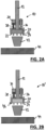
- Fig. 2A is a schematic representation of the tool 10 from Fig. 1 shown.
- the tool 10 is designed and set up to receive a setting element 42 on the front side, hold it and introduce it into a component 44.
- FIG. 2B a schematic diagram of a tool 10' is shown.
- This tool 10' is different from the one in Fig. 1 and 2A tool 10 shown only in that a clearing nose 46 is provided on the inclined diverter surface 22.
- the clearing nose 46 is arranged in a portion of the diverting surface 22 and serves to remove melt 54 or a bead 56 provided with a predetermined breaking point 26.
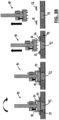
- FIG. 3A and 3B A process sequence is shown, which shows how a setting element 42 can be introduced into a component 44 using the previously described tool 10 and a predetermined breaking point 26 can be created in a bead 56.
- the setting element 42 is first rotated using the tool 10 and then the end face 48 of the setting element 42, which is removed from the tool, is placed on a cover layer 50 of the component 44.
- the cover layer 50 of the component 44 heats up and becomes softer.
- the cover layer 50 is softened so that the setting element 42 can penetrate the cover layer 50.
- the melt 54 created by melting the cover layer 50 and a core 52 accumulates in an annular area which surrounds the setting element 42.
- an ever larger amount of melt 54 accumulates in the area surrounding the setting element 42.
- the edge 24 of the predetermined breaking point generating element 20 is pressed further into the melt 54, more precisely into a radially inner region of the melt 54, by a further feed movement of the tool 10. This creates the edge 24 of the predetermined breaking point generating element 20 the ring-shaped predetermined breaking point 26 (see Fig. 5C , right). While the predetermined breaking point generating element 20 is pressed into the melt 54, the predetermined breaking point generating element 20 is axially displaced against a restoring force of the spring element 38. By setting a corresponding restoring force of the spring element 38, it can be ensured that the predetermined breaking point generating element 20 does not completely cut through the melt 54, but that a connection is maintained.
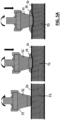
- FIGS. 4A and 4B show a corresponding setting process with the tool 10 'according to Fig. 2B .
- the clearing nose 46 By dipping the edge 24 into the melt (see right picture of the Fig. 4A ), the clearing nose 46 also comes into contact with the melt 54.
- the clearing nose 46 continuously deforms part of the melt 54, so that a flatter bead 56 is created.
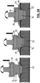
- the predetermined breaking point 26 is created during the setting process with the tool 10.
- the cover layer 50 is heated.
- the cover layer 50 is melted and forms a crater.
- Excess melt 54 is pushed outwards and is deposited laterally next to the setting element 42 in an area not surrounded by the tool 10.
- the edge 24 of the predetermined breaking point generating element 20 dips into the melt 54. Due to a further feed movement, the edge 24 of the predetermined breaking point generating element 20 dips further into the melt 54, so that the entire oblique discharge surface 22 of the predetermined breaking point generating element 20 is immersed in the melt 54.
- a resistance acting from the melt 54 on the predetermined breaking point generating element 20 increases until it overcomes a restoring force of the spring element 38.
- the predetermined breaking point generating element 20 moves relative to the drive shaft 12 against the restoring force of the spring element 38 in the direction of the proximal end 12a of the drive shaft 12. This makes it possible, as in the left picture of Fig. 5C can be seen, a transition between the melt 54a immediately surrounding the setting element 42 and the bead-shaped melt 54b is maintained. This transition serves as a predetermined breaking point 26 in order to detach the bead 56 from the remaining solidified melt 57.
Landscapes
- Engineering & Computer Science (AREA)
- Mechanical Engineering (AREA)
- Physics & Mathematics (AREA)
- Thermal Sciences (AREA)
- Milling, Broaching, Filing, Reaming, And Others (AREA)
Description
- Die Erfindung betrifft ein Werkzeug und ein Verfahren zum Setzen eines Setzelements in einem Bauteil unter Erzeugung einer Reibschweißverbindung zwischen dem Setzelement und dem Bauteil.
- Solche Werkzeuge und Verfahren sind grundsätzlich bekannt und werden u.a. dazu verwendet, sogenannte Kunststoffdome in Sandwichstrukturen mit einem Waben- oder Schaumkern und Deckschichten aus faserverstärkten Kunststoffen einzubringen.
- Zum Einbringen eines Setzelements, z.B. eines Kunststoffdoms, wird eine Antriebswelle, deren Stirnfläche mit einer Rückseite des Setzelements in Kontakt steht, von einer Rotationsvorschubeinheit in Rotation versetzt. Zusätzlich wird das sich drehende Setzelement von der Rotationsvorschubeinheit mit einer in Richtung der Drehachse wirkenden Axialkraft auf das Bauteil, z.B. auf die Deckschicht aus faserverstärktem Kunststoff, gedrückt, sodass sich das Setzelement und die Deckschicht durch Reibung erwärmen. Sobald die Deckschicht durchdrungen ist, kann sich das Setzelement durch die Deckschicht hindurch in den Kern der Sandwichstruktur hineinbohren. Wenn die Deckschicht und der Kern wieder erkalten, entsteht eine Reibschweißverbindung zwischen dem Setzelement und dem Bauteil.
- Während des Setzprozesses verdrängt das Setzelement aufgeschmolzenes Material des Bauteils und des Setzelements. Das verdrängte Material bildet einen das Setzelement umgebenden Wulst an der Oberfläche des Bauteils, wodurch das Bauteil seine ursprüngliche Oberflächenform im Bereich des Wulstes verliert. Dies ist insbesondere dann von Nachteil, wenn eine glatte Bauteiloberfläche gewünscht ist. Eine glatte Bauteiloberfläche kann beispielsweise vorteilhaft sein, wenn das Bauteil mit einem anderen Bauteil verbunden werden soll und die Bauteile flächig aneinander anliegen sollen.
- Die Dokumente
WO 2015/120900 A1 undEP 2 732 956 A1 offenbaren ein Werkzeug mit den Merkmalen des Oberbegriffs des Anspruchs 1. Die offenbarten Werkzeuge weisen Schneidmittel auf, die dazu dienen, den das Setzelement umgebenden Wulst abzuschneiden oder abzufräsen. - Es ist eine Aufgabe der vorliegenden Erfindung, ein Werkzeug und ein Verfahren bereitzustellen, welche es auf einfache Weise ermöglichen, einen Setzprozess durchzuführen und dabei eine im Wesentlichen glatte Bauteiloberfläche zu erhalten, ohne die Bauteiloberfläche zu beschädigen.
- Die Aufgabe wird gelöst durch ein Werkzeug mit den Merkmalen des Anspruchs 1.
- Das Sollbruchstellenerzeugungselement ist dazu ausgebildet und eingerichtet, eine Sollbruchstelle in dem durch den Setzprozess entstehenden Wulst zu erzeugen, um diesen anschließend einfach entfernen zu können.
- Vorteilhafte Ausbildungen der Erfindung sind den Unteransprüchen, der Beschreibung und der Zeichnung zu entnehmen.
- Gemäß einer Ausführungsform bildet eine Ableitfläche des Sollbruchstellenerzeugungselements zumindest abschnittsweise eine Kante. Diese ist vorzugsweise dazu ausgebildet, eine ringförmige Sollbruchstelle in einem Wulst zu erzeugen, welcher beim Setzen des Setzelements um das Setzelement herum entsteht. Dabei kann das Sollbruchstellenerzeugungselement dazu ausgebildet und eingerichtet sein, in die noch nicht wiedererstarrte Schmelze einzutauchen und dabei eine Sollbruchstelle zu erzeugen.
- Vorzugsweise ist das Sollbruchstellenerzeugungselement axial beweglich an der Antriebswelle angeordnet. Speziell kann ein axialer Abstand zwischen der Kante des Sollbruchstellenerzeugungselements und einer Stirnfläche der Antriebswelle, mit der die Antriebswelle mit einer Rückseite des Setzelements in Kontakt steht, veränderbar sein. Hierdurch kann verhindert werden, dass das Sollbruchstellenerzeugungselement beim Setzprozess den Wulst vollständig durchtrennt und so auf die Deckschicht auftrifft.
- Gemäß einer Ausführungsform ist das Sollbruchstellenerzeugungselement entgegen einer Federkraft in Richtung eines proximalen Endes der Antriebswelle beweglich. Vorzugsweise ist ein Federelement zwischen das Sollbruchstellenerzeugungselement und einen Abschnitt der Antriebswelle geschaltet, welches durch eine Bewegung des Sollbruchstellenerzeugungselements in Richtung eines proximalen Endes der Antriebswelle aufladbar ist. Als proximales Ende der Antriebswelle wird das antriebsseitige Ende der Antriebswelle angesehen, d.h. dasjenige Ende der Antriebswelle, welches von einer Aufnahme für das Setzelement beabstandet ist.
- Um das Werkzeug auf unterschiedliche Materialien anpassen zu können, kann die Federkraft einstellbar sein. Insbesondere können Einstellmittel vorgesehen sein, um eine Rückstellkraft des Federelements verändern bzw. einstellen zu können. Beispielsweise kann das Federelement durch die Einstellmittel vorgespannt werden, sodass die Rückstellkraft des Federelements erhöht wird.
- Gemäß einer Ausführungsform kann das Sollbruchstellenerzeugungselement drehfest mit der Antriebswelle gekoppelt sein. Hierdurch kann die Drehbewegung der Antriebswelle vollständig zur Erzeugung einer Sollbruchstelle verwendet werden. Alternativ dazu kann eine Drehbewegung der Antriebswelle mittels Reibung auf das Sollbruchstellenerzeugungselement übertragen werden. Gemäß einer Variante entkoppelt sich das Sollbruchstellenerzeugungselement bei einer Überlast selbsttätig von der Antriebswelle, sodass eine rotative Relativbewegung zwischen Sollbruchstellenerzeugungselement und Antriebswelle möglich ist. Alternativ dazu kann das Sollbruchstellenerzeugungselement im Gebrauch stets drehfest mit der Antriebswelle verbunden sein und zu keinem Zeitpunkt eine rotative Relativbewegung zwischen Sollbruchstellenerzeugungselement und Antriebswelle möglich sein.
- Um ein seitliches Abfließen der Schmelze zu unterstützen, weist das Sollbruchstellenerzeugungselement vorteilhafterweise zumindest abschnittsweise eine schräge Ableitfläche auf. Vorzugsweise erstreckt sich die schräge Ableitfläche über die gesamte Stirnseite, d.h. von einer inneren Stirnkante zu einer äußeren Stirnkante.
- Bei Versuchen hat sich herausgestellt, dass ein Winkel α, gemessen zwischen der schrägen Ableitfläche und der Antriebsachse, vorzugsweise in einem Bereich zwischen 10° und 60°, insbesondere zwischen 25° und 35°, liegt. Hierdurch kann die Schmelze besonders gut seitlich abfließen und es bildet sich ein gut zu entfernender Wulst.
- Um ein Eindringen der Schmelze in einen Zwischenraum zwischen dem Sollbruchstellenerzeugungselement und der Antriebswelle zu begrenzen, ist es vorteilhaft, wenn ein Außendurchmesser der Antriebswelle zumindest in einem axialen Bereich im Wesentlichen dem entsprechenden Innendurchmesser des Sollbruchstellenerzeugungselements entspricht. Dabei ist zu beachten, dass der Außendurchmesser der Antriebswelle stets kleiner als der Innendurchmesser des Sollbruchstellenerzeugungselements gewählt werden sollte, damit eine Relativbewegung zwischen Antriebswelle und Sollbruchstellenerzeugungselement möglich bleibt.
- Um Schmelze oder den durch die Sollbruchstelle von der restlichen Schmelze getrennten Wulst abzutragen, kann zumindest eine Räumnase vorgesehen sein.
- Diese Räumnase ist vorzugsweise an dem Sollbruchstellenerzeugungselement angeordnet. Insbesondere kann die Räumnase auf der Ableitfläche, beispielsweise der schrägen Ableitfläche, angeordnet sein. Die Räumnase kann eine zweite Ableitfläche aufweisen, welche sich in einem Winkel zur Antriebsachse erstreckt, der größer als der Winkel α ist.
- Die Erfindung betrifft ferner ein Verfahren zum Setzen eines Setzelements in einem Bauteil unter Erzeugung einer Reibschweißverbindung zwischen dem Setzelement und dem Bauteil, insbesondere mittels eines Werkzeugs gemäß einer der vorstehend oder nachfolgend beschriebenen Ausführungsformen, umfassend: Einbringen des Setzelementes in das Bauteil unter Erzeugung einer relativen Rotationsbewegung zwischen dem Setzelement und dem Bauteil und einer relativen axialen Vorschubbewegung zwischen dem Setzelement und dem Bauteil und Erzeugen einer Sollbruchstelle in einem Wulst, welcher beim Setzen des Setzelements um das Setzelement herum entsteht.
- Vorzugsweise wird die Sollbruchstelle in Form einer Kerbe in der erstarrten Schmelze ausgeformt. Hierdurch wird die Schmelze lokal geschwächt, sodass ein Teil der Schmelze auf einfache Weise abgetrennt werden kann.
- Vorteilhafterweise wird die Sollbruchstelle durch ein Eindrücken bzw. Eintauchen eines Sollbruchstellenerzeugungselements generiert. Insbesondere kann das Sollbruchstellenerzeugungselement in die flüssige bzw. teigige Schmelze des Wulsts eingedrückt werden.
- Gemäß einer Ausführungsform wird die Sollbruchstelle als umlaufende Nut ausgebildet. In anderen Worten wird eine um die Antriebsachse bzw. eine Mittelachse des Setzelements umlaufende Nut gebildet. Die ringförmige Nut weist vorzugsweise einen Durchmesser auf, welcher größer als der größte Durchmesser des Setzelements ist.
- Gemäß einer Ausführungsform kann die Nut so ausgeformt werden, dass diese eine Außenfläche und eine Innenfläche aufweist, welche in einem Winkel zueinander angeordnet sind. Vorzugsweise schneiden sich die Außenfläche und die Innenfläche, sodass die Nut einen v-förmigen Querschnitt aufweist. Hierzu kann ein im Querschnitt spitz zulaufendes Sollbruchstellenerzeugungselement verwendet werden. Das Sollbruchstellenerzeugungselement wird vorzugsweise in einen, dem Setzelement zugewandten, Randbereich des Wulstes hineingedrückt.
- Vorteilhafterweise weist die Innenfläche einen kleineren Winkel zur Antriebsachse auf als die Außenfläche. Beispielsweise kann die Innenfläche einen Winkel zwischen 0° und 5°, insbesondere von im Wesentlichen 0°, zur Antriebsachse aufweisen. Die Außenfläche weist vorzugsweise einen Winkel zwischen 25° und 35° zur Antriebsachse auf.
- Nachfolgend wird die Erfindung anhand einer rein beispielhaften Ausführungsform unter Bezugnahme auf die beigefügten Zeichnungen beschrieben. Es zeigen:
- Fig. 1
- eine seitliche Schnittansicht eines erfindungsgemäßen Werkzeugs;
- Fig. 2A
- eine Prinzipdarstellung des Werkzeugs von
Fig. 1 ; - Fig. 2B
- eine Prinzipdarstellung eines zweiten erfindungsgemäßen Werkzeugs;
- Fig. 3A
- einen ersten Teil eines Ablaufdiagramms eines erfindungsgemäßen Verfahrens;
- Fig. 3B
- einen zweiten Teil des Ablaufdiagramms des erfindungsgemäßen Verfahrens von
Fig. 3A ; - Fig. 4A
- einen ersten Teil eines Ablaufdiagramms eines zweiten erfindungsgemäßen Verfahrens;
- Fig. 4B
- einen zweiten Teil des Ablaufdiagramms des zweiten erfindungsgemäßen Verfahrens von
Fig. 4A ; - Fig. 5A
- eine Detailansicht eines ersten Teils eines Ablaufdiagramms eines erfindungsgemäßen Verfahrens;
- Fig. 5B
- eine Detailansicht eines zweiten Teils des Ablaufdiagramms von
Fig. 5A ; - Fig. 5C
- eine Detailansicht eines dritten Teils des Ablaufdiagramms von
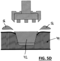
Fig. 5A ; und - Fig. 5D
- eine Detailansicht eines vierten Teils des Ablaufdiagramms von
Fig. 5A . - In
Fig. 1 ist ein Werkzeug 10 zum Setzen eines Setzelements 42 (Fig. 2A ) in einem Bauteil unter Erzeugung einer Reibschweißverbindung zwischen dem Setzelement 42 und dem Bauteil gezeigt. Das Werkzeug 10 umfasst eine Antriebswelle 12, welche sich entlang einer Antriebsachse 14 erstreckt und sich mittels eines nicht gezeigten Rotationsantriebs in Rotation um die Antriebsachse 14 versetzen lässt. Die Antriebswelle 12 weist ein erstes, proximales Ende 12a auf, welches dazu ausgebildet und eingerichtet ist, mit einer Spannvorrichtung einer Rotationsvorschubeinheit verbunden zu werden. Hierzu weist die Antriebswelle 12 Kopplungsmittel 16 zur formschlüssigen Kopplung mit nicht gezeigten Spannmitteln auf. An einem zweiten, distalen Ende 12b der Antriebswelle 12 sind Haltemittel 18 vorgesehen, um das Setzelement 42, beispielsweise einen Reibschweißdom, an der Antriebswelle 12 zu fixieren. Die Haltemittel 18 sind vorzugsweise, wie inFig. 1 gezeigt, dezentral angeordnet, um mittels Formschluss ein Drehmoment auf das Setzelement 42 übertragen zu können. - Die Antriebswelle 12 ist an ihrem distalen Endbereich 12b von einem Sollbruchstellenerzeugungselement 20 vollständig umgeben. Das Sollbruchstellenerzeugungselement 20 weist eine schräge Ableitfläche 22 auf, welche einen Winkel α von 30° mit der Antriebsachse einschließt und daher an ihrem Innenumfang eine spitze Kante 24 aufweist. Die Kante 24 ist dazu ausgebildet und eingerichtet, eine ringförmige Sollbruchstelle 26 (siehe
Fig. 5C ) in einem Wulst 56 zu erzeugen, welcher beim Setzen eines Setzelements 42 um das Setzelement 42 herum entsteht. - Wie ebenfalls in
Fig. 1 zu sehen ist, weist das Werkzeug 10 zudem ein Drehmomentübertragungselement 30, hier in Form einer Hülse, auf, um ein Drehmoment von der Antriebswelle 12 auf das Sollbruchstellenerzeugungselement 20 zu übertragen. Hierzu ist das Drehmomentübertragungselement 30, beispielsweise mittels einer Presspassung, fest mit der Antriebswelle 12 verbunden. Zudem ist in dem Sollbruchstellenerzeugungselement 20 zumindest eine Bohrung 32 und in dem Drehmomentübertragungselement 30 zumindest eine Bohrung 34 vorgesehen. Die Bohrungen 32 und 34 sind konzentrisch zueinander ausgerichtet und dienen dazu, gemeinsam eine Stange 36 aufzunehmen. Über das Drehmomentübertragungselement 30 und die Stange 36 wird das an der Antriebswelle 12 anliegende Drehmoment auf das Sollbruchstellenerzeugungselement 20 übertragen, sodass sich die Antriebswelle 12 und das Sollbruchstellenerzeugungselement 20 gleichförmig um die Antriebsachse 14 drehen. Vorzugsweise sind, wie inFig. 1 gezeigt, zumindest zwei Bohrungen 32, zwei Bohrungen 34 und zwei Stangen 36 vorgesehen, um eine sichere Drehmomentübertragung zu gewährleisten. - Damit sich das Sollbruchstellenerzeugungselement 20 in axialer Richtung relativ zu der Antriebswelle 12 bewegen kann, hat die zumindest eine Bohrung 34 einen breiteren Durchmesser als die zumindest eine Stange 36. Hierdurch lässt sich die zumindest eine Stange 36 in der zumindest einen Bohrung 34 verschieben. Die Stange 36 dient somit nicht nur zur Drehmomentübertragung, sondern zudem noch zur Führung einer axialen Relativbewegung zwischen dem Sollbruchstellenerzeugungselement 20 und der Antriebswelle 12.
- Um das Sollbruchstellenerzeugungselement 20 in eine Ausgangsposition (siehe
Fig. 1 ) vorzuspannen, ist ein Federelement 38 zwischen das Sollbruchstellenerzeugungselement 20 und das Drehmomentübertragungselement 30 geschaltet. Das Federelement 38, welches in der gezeigten Ausführungsform als Spiralfeder ausgebildet ist, ist durch eine Bewegung des Sollbruchstellenerzeugungselements 20 relativ zur Antriebswelle 12 auf das Drehmomentübertragungselement 30 zu spannbar. In anderen Worten erhöht sich eine Rückstellkraft des Federelements 38, wenn das Sollbruchstellenerzeugungselement 20 aus der Ausgangsposition in Richtung des ersten Endes 12a der Antriebswelle 12 bewegt wird. - Um das Sollbruchstellenerzeugungselement 20 auf einfache Weise verliersicher auf der Antriebswelle 12 anzuordnen, weist die Antriebswelle 12 eine Querschnittsvergrößerung 40 und das Sollbruchstellenerzeugungselement 20 eine korrespondierende Querschnittsverkleinerung 43 auf. Die Querschnittsvergrößerung 40 dient dazu, eine axiale Bewegung des Sollbruchstellenerzeugungselements 20 in Richtung des distalen Endes 12b zu limitieren.
- Die Querschnittsvergrößerung 40 hat einen Außendurchmesser a, welcher im Wesentlichen einem Innendurchmesser i des Sollbruchstellenerzeugungselements 20 entspricht. Der Außendurchmesser a ist dabei nur geringfügig kleiner als der Innendurchmesser i, damit sich das Sollbruchstellenerzeugungselement 20 relativ zur Antriebsachse axial bewegen lässt.
- In
Fig. 2A ist eine Prinzipdarstellung des Werkzeugs 10 vonFig. 1 gezeigt. Das Werkzeug 10 ist dazu ausgebildet und eingerichtet, ein Setzelement 42 stirnseitig aufzunehmen, zu halten und in ein Bauteil 44 einzubringen. - In
Fig. 2B ist eine Prinzipdarstellung eines Werkzeugs 10' gezeigt. Dieses Werkzeug 10' unterscheidet sich von dem inFig. 1 und2A gezeigten Werkzeug 10 lediglich dadurch, dass an der schrägen Ableitfläche 22 eine Räumnase 46 vorgesehen ist. Die Räumnase 46 ist in einem Teilbereich der Ableitfläche 22 angeordnet und dient dazu, Schmelze 54 oder einen mit einer Sollbruchstelle 26 versehenen Wulst 56 abzutragen. - In den
Figuren 3A und3B ist ein Verfahrensablauf dargestellt, welcher zeigt, wie mit dem zuvor beschriebenen Werkzeug 10 ein Setzelement 42 in ein Bauteil 44 eingebracht und dabei eine Sollbruchstelle 26 in einem Wulst 56 erzeugt werden kann. - Im Bild links außen wird zunächst das Setzelement 42 mittels des Werkzeugs 10 rotiert und anschließend die von dem Werkzeug entfernte Stirnseite 48 des Setzelements 42 auf eine Deckschicht 50 des Bauteils 44 aufgesetzt. Hierdurch erwärmt sich die Deckschicht 50 des Bauteils 44 und wird weicher. Im Bild rechts daneben ist die Deckschicht 50 aufgeweicht, sodass das Setzelement 42 die Deckschicht 50 durchdringen kann. Die durch ein Aufschmelzen der Deckschicht 50 und eines Kerns 52 entstehende Schmelze 54 sammelt sich in einem ringförmigen Bereich, welcher das Setzelement 42 umgibt, an. Im Bild daneben ist zu sehen, dass sich durch ein immer tieferes Eindringen des Setzelements 42 in das Bauteil 44 eine immer größere Menge der Schmelze 54 in dem das Setzelement 42 umgebenden Bereich ansammelt.
- Im rechten Bild von
Fig. 3A ist zu sehen, dass ab einer bestimmten Eindringtiefe des Setzelements 42 bzw. einem bestimmten Tiefenwert des Werkzeugs vor einer Endposition des Setzelements 42 das Sollbruchstellenerzeugungselement 20 mit der wulstförmigen Schmelze 54 in Kontakt kommt. Dabei dreht sich das Werkzeug 10 weiterhin um die Antriebsachse 14. - Im linken Bild von
Fig. 3B wird die Kante 24 des Sollbruchstellenerzeugungselements 20 durch eine weitere Vorschubbewegung des Werkzeugs 10 weiter in die Schmelze 54, genauer gesagt in einen radial inneren Bereich der Schmelze 54, eingedrückt. Dabei erzeugt die Kante 24 des Sollbruchstellenerzeugungselements 20 die ringförmig umlaufende Sollbruchstelle 26 (sieheFig. 5C , rechts). Während des Eindrückens des Sollbruchstellenerzeugungselements 20 in die Schmelze 54 wird das Sollbruchstellenerzeugungselement 20 entgegen einer Rückstellkraft des Federelements 38 axial verschoben. Durch Einstellen einer entsprechenden Rückstellkraft des Federelements 38 kann sichergestellt werden, dass das Sollbruchstellenerzeugungselement 20 die Schmelze 54 nicht vollständig durchtrennt, sondern eine Verbindung erhalten bleibt. - Wenn das Setzelement 42 seine vorgesehene Endposition erreicht hat, werden die Vorschubbewegung und die Drehbewegung des Werkzeugs 10 gestoppt. Nach einer Abkühlphase wird das Werkzeug 10 entgegen der Vorschubrichtung zurückgezogen. Der mit dem Bauteil 44 über die Sollbruchstelle 26 verbundene, erkaltete Wulst 56 kann anschließend auf einfache Weise abgetragen werden.
- Die
Figuren 4A und4B zeigen einen entsprechenden Setzprozess mit dem Werkzeug 10' gemäßFig. 2B . Mit dem Eintauchen der Kante 24 in die Schmelze (siehe rechtes Bild derFig. 4A ) kommt auch die Räumnase 46 mit der Schmelze 54 in Kontakt. Die Räumnase 46 verformt kontinuierlich einen Teil der Schmelze 54, sodass ein flacherer Wulst 56 entsteht. - In den
Fig. 5A bis 5D ist noch einmal detaillierter gezeigt, wie die Sollbruchstelle 26 beim Setzprozess mit dem Werkzeug 10 erzeugt wird. Durch ein Reiben des Setzelements 42 auf der Deckschicht 50 wird die Deckschicht 50 erwärmt. Hierdurch wird die Deckschicht 50 aufgeschmolzen und bildet einen Krater. Überschüssige Schmelze 54 wird nach außen gedrängt und lagert sich seitlich neben dem Setzelement 42 in einem nicht vom Werkzeug 10 umgebenen Bereich ab. In dem mittleren Bild vonFig. 5B taucht die Kante 24 des Sollbruchstellenerzeugungselements 20 in die Schmelze 54 ein. Durch eine weitere Vorschubbewegung taucht die Kante 24 des Sollbruchstellenerzeugungselements 20 weiter in die Schmelze 54 ein, sodass die gesamte schräge Ableitfläche 22 des Sollbruchstellenerzeugungselements 20 in die Schmelze 54 eintaucht. Dabei steigt ein von der Schmelze 54 auf das Sollbruchstellenerzeugungselement 20 wirkender Widerstand an, bis dieser eine Rückstellkraft des Federelements 38 überwindet. Im linken Bild vonFig. 5C ist zu sehen, dass sich das Sollbruchstellenerzeugungselement 20 relativ zur Antriebswelle 12 entgegen der Rückstellkraft des Federelements 38 in Richtung des proximalen Endes 12a der Antriebswelle 12 bewegt. Hierdurch wird ermöglicht, dass, wie im linken Bild vonFig. 5C zu sehen ist, ein Übergang zwischen der, das Setzelement 42 unmittelbar umgebenden, Schmelze 54a und der wulstförmigen Schmelze 54b erhalten bleibt. Dieser Übergang dient als Sollbruchstelle 26, um den Wulst 56 von der restlichen erstarrten Schmelze 57 abzulösen. -
- 10
- Werkzeug
- 12
- Antriebswelle
- 14
- Antriebsachse
- 16
- Kopplungsmittel
- 18
- Haltemittel
- 20
- Sollbruchstellenerzeugungselement
- 22
- Ableitfläche
- 24
- Kante
- 26
- Sollbruchstelle
- 30
- Drehmomentübertragungselement
- 32
- Bohrung
- 34
- Bohrung
- 36
- Stange
- 38
- Federelement
- 40
- Querschnittsvergrößerung
- 42
- Setzelement
- 43
- Querschnittsverkleinerung
- 44
- Bauteil
- 46
- Räumnase
- 48
- Stirnseite (Setzelement)
- 50
- Deckschicht
- 52
- Kern
- 54
- Schmelze
- 56
- Wulst
- 57
- restliche erstarrte Schmelze
- α
- Winkel
- a
- Außendurchmesser
- i
- Innendurchmesser
Claims (15)
- Werkzeug (10; 10') zum Setzen eines Setzelements (42) in einem Bauteil (44) unter Erzeugung einer Reibschweißverbindung zwischen dem Setzelement (42) und dem Bauteil (44), umfassend:eine in Rotation um eine Antriebsachse (14) versetzbare Antriebswelle (12) zum Übertragen eines Drehmoments auf das Setzelement (42),gekennzeichnet durchein sich zumindest abschnittsweise um die Antriebsachse (14) herum erstreckendes Sollbruchstellenerzeugungselement (20).
- Werkzeug (10; 10') nach Anspruch 1,
dadurch gekennzeichnet,
dass eine Ableitfläche (22) des Sollbruchstellenerzeugungselements (20) zumindest abschnittsweise eine Kante (24) bildet, welche dazu ausgebildet ist, eine ringförmige Sollbruchstelle (26) in einem Wulst (56) zu erzeugen, welcher beim Setzen des Setzelements (42) um das Setzelement (42) herum entsteht. - Werkzeug (10; 10') nach Anspruch 1 oder 2,
dadurch gekennzeichnet,
dass das Sollbruchstellenerzeugungselement (20) axial beweglich an der Antriebswelle (12) angeordnet ist. - Werkzeug (10; 10') nach Anspruch 3,
dadurch gekennzeichnet,
dass das Sollbruchstellenerzeugungselement (20) entgegen einer Federkraft in Richtung eines proximalen Endes (12a) der Antriebswelle (12) beweglich ist. - Werkzeug (10; 10') nach Anspruch 4,
dadurch gekennzeichnet,
dass die Federkraft einstellbar ist. - Werkzeug (10; 10') nach einem der vorstehenden Ansprüche,
dadurch gekennzeichnet,
dass das Sollbruchstellenerzeugungselement (20) drehfest mit der Antriebswelle (12) gekoppelt ist. - Werkzeug (10; 10') nach einem der vorstehenden Ansprüche,
dadurch gekennzeichnet,
dass das Sollbruchstellenerzeugungselement (20) zumindest abschnittsweise eine schräge Ableitfläche (22) aufweist. - Werkzeug (10; 10') nach Anspruch 7,
dadurch gekennzeichnet,
dass ein Winkel α zwischen der schrägen Ableitfläche (22) und der Antriebsachse (14) in einem Bereich zwischen 10° und 60°, insbesondere in einem Bereich zwischen 25° und 35°, liegt. - Werkzeug (10; 10') nach einem der vorstehenden Ansprüche,
dadurch gekennzeichnet,
dass das Sollbruchstellenerzeugungselement (20) einen Innendurchmesser (i) aufweist, und die Antriebswelle (12) einen Außendurchmesser (a) aufweist, und dass der Außendurchmesser (a) der Antriebswelle (12) zumindest abschnittsweise im Wesentlichen dem Innendurchmesser (i) des Sollbruchstellenerzeugungselements (20) entspricht. - Werkzeug (10') nach einem der vorstehenden Ansprüche,
dadurch gekennzeichnet,
dass zumindest eine Räumnase (46) vorgesehen ist. - Werkzeug (10') nach Anspruch 10,
dadurch gekennzeichnet,
dass die Räumnase (46) an dem Sollbruchstellenerzeugungselement (20) angeordnet ist. - Verfahren zum Setzen eines Setzelements (42) in einem Bauteil (44) unter Erzeugung einer Reibschweißverbindung zwischen dem Setzelement (42) und dem Bauteil (44), insbesondere mittels eines Werkzeugs (10; 10') gemäß zumindest einem der vorherigen Ansprüche, umfassend:Einbringen des Setzelementes (42) in das Bauteil (44) unter Erzeugung einer relativen Rotationsbewegung zwischen dem Setzelement (42) und dem Bauteil (44) und einer relativen axialen Vorschubbewegung zwischen dem Setzelement (42) und dem Bauteil (44);gekennzeichnet durchErzeugen einer Sollbruchstelle (26) in einem Wulst (56), welcher beim Setzen des Setzelements (42) um das Setzelement (42) herum entsteht.
- Verfahren nach Anspruch 12,
dadurch gekennzeichnet,
dass die Sollbruchstelle als umlaufende Nut (26) ausgebildet ist. - Verfahren nach Anspruch 13,
dadurch gekennzeichnet,
dass die Nut (26) einen v-förmigen Querschnitt aufweist. - Verfahren nach Anspruch 12 oder 13
dadurch gekennzeichnet,
dass die Nut (26) eine Außenfläche und eine Innenfläche aufweist, und dass die Innenfläche einen kleineren Winkel zur Antriebsachse (14) aufweist als die Außenfläche.
Priority Applications (1)
| Application Number | Priority Date | Filing Date | Title |
|---|---|---|---|
| EP19206654.6A EP3815882B1 (de) | 2019-10-31 | 2019-10-31 | Werkzeug und verfahren zum setzen eines setzelements |
Applications Claiming Priority (1)
| Application Number | Priority Date | Filing Date | Title |
|---|---|---|---|
| EP19206654.6A EP3815882B1 (de) | 2019-10-31 | 2019-10-31 | Werkzeug und verfahren zum setzen eines setzelements |
Publications (2)
| Publication Number | Publication Date |
|---|---|
| EP3815882A1 EP3815882A1 (de) | 2021-05-05 |
| EP3815882B1 true EP3815882B1 (de) | 2024-01-10 |
Family
ID=68426155
Family Applications (1)
| Application Number | Title | Priority Date | Filing Date |
|---|---|---|---|
| EP19206654.6A Active EP3815882B1 (de) | 2019-10-31 | 2019-10-31 | Werkzeug und verfahren zum setzen eines setzelements |
Country Status (1)
| Country | Link |
|---|---|
| EP (1) | EP3815882B1 (de) |
Family Cites Families (2)
| Publication number | Priority date | Publication date | Assignee | Title |
|---|---|---|---|---|
| DE202012011021U1 (de) * | 2012-11-16 | 2014-02-17 | Ejot Gmbh & Co. Kg | Setzwerkzeugsytem |
| EP3105039B1 (de) * | 2014-02-14 | 2019-04-10 | EJOT GmbH & Co. KG | Setzwerkzeug zum setzen eines reibschweissdoms |
-
2019
- 2019-10-31 EP EP19206654.6A patent/EP3815882B1/de active Active
Also Published As
| Publication number | Publication date |
|---|---|
| EP3815882A1 (de) | 2021-05-05 |
Similar Documents
| Publication | Publication Date | Title |
|---|---|---|
| DE69624656T2 (de) | Bohrwerkzeugvorrichtung mit Zentrierbohrer und Hohlbohrkrone | |
| EP0085888B1 (de) | Verfahren zum Herstellen eines beidendig mit einer Randverstärkung versehenen Durchgangsloches in einem Metallwerkstück sowie Werkzeug zur Durchführung dieses Verfahrens | |
| DE69535730T2 (de) | Schmiedeverfahren | |
| DE69522201T2 (de) | Werkzeughalter | |
| EP2603340B1 (de) | Werkzeughalter | |
| EP2732956B1 (de) | Setzwerkzeugsystem | |
| EP2596898A1 (de) | Selbstspannendes Reibschweißwerkzeug | |
| DE102012023437B4 (de) | Rundlaufoptimiertes Werkzeugspannsystem für Dentalwinkelhandstücke und Dentalturbinen | |
| WO1999006170A1 (de) | Vorrichtung zum bruchtrennen eines ringförmigen bauteils | |
| DE102010061546B4 (de) | Vorrichtung und Verfahren zum Lösen von Elektrodenkappen | |
| EP2087963A2 (de) | Reibschweißverfahren | |
| EP3815882A1 (de) | Werkzeug und verfahren zum setzen eines setzelements | |
| DE3110348C2 (de) | Spannfutter für ein Drehwerkzeug | |
| EP3105039B1 (de) | Setzwerkzeug zum setzen eines reibschweissdoms | |
| DE2446776A1 (de) | Verfahren zur herstellung von bohrfuttern | |
| DE102009040527A1 (de) | Werzeug zum Rührreibschweißen und Verfahren | |
| WO2024013185A1 (de) | Längeneinstellvorrichtung zu einer einstellung einer längsposition eines werkzeugs, werkzeugspanngerät und system und verfahren mit der längeneinstellvorrichtung | |
| EP3755526B1 (de) | Vorrichtung zum setzen eines setzelements | |
| EP3566801B1 (de) | Schrumpfspannadapter fuer ein spannzangenfutter | |
| DE102011000314A1 (de) | Verfahren zur Demontage eines Rundschaftmeißels, Rundschaftmeißel sowie Ausziehwerkzeug | |
| EP1738846B1 (de) | Vorrichtung zum Lösen einer Einpressmutter oder Hohlnietverbindung | |
| WO2005107986A1 (de) | Räumwerkzeug und verfahren zur spanenden bearbeitung von bohrungsoberflächen | |
| DE112005002006T5 (de) | Induktionshärteverfahren und in einem Induktionshärtevorgang verwendete Vorrichtung | |
| EP2977135A1 (de) | Vorrichtung und Verfahren zum Erstellen einer Vertiefung in Dämmstoffen | |
| EP3824198A1 (de) | Welle-nabe-verbindung und verfahren zum herstellen einer welle-nabe-verbindung |
Legal Events
| Date | Code | Title | Description |
|---|---|---|---|
| PUAI | Public reference made under article 153(3) epc to a published international application that has entered the european phase |
Free format text: ORIGINAL CODE: 0009012 |
|
| STAA | Information on the status of an ep patent application or granted ep patent |
Free format text: STATUS: THE APPLICATION HAS BEEN PUBLISHED |
|
| AK | Designated contracting states |
Kind code of ref document: A1 Designated state(s): AL AT BE BG CH CY CZ DE DK EE ES FI FR GB GR HR HU IE IS IT LI LT LU LV MC MK MT NL NO PL PT RO RS SE SI SK SM TR |
|
| STAA | Information on the status of an ep patent application or granted ep patent |
Free format text: STATUS: REQUEST FOR EXAMINATION WAS MADE |
|
| 17P | Request for examination filed |
Effective date: 20210720 |
|
| RBV | Designated contracting states (corrected) |
Designated state(s): AL AT BE BG CH CY CZ DE DK EE ES FI FR GB GR HR HU IE IS IT LI LT LU LV MC MK MT NL NO PL PT RO RS SE SI SK SM TR |
|
| GRAP | Despatch of communication of intention to grant a patent |
Free format text: ORIGINAL CODE: EPIDOSNIGR1 |
|
| STAA | Information on the status of an ep patent application or granted ep patent |
Free format text: STATUS: GRANT OF PATENT IS INTENDED |
|
| INTG | Intention to grant announced |
Effective date: 20230726 |
|
| GRAS | Grant fee paid |
Free format text: ORIGINAL CODE: EPIDOSNIGR3 |
|
| GRAA | (expected) grant |
Free format text: ORIGINAL CODE: 0009210 |
|
| STAA | Information on the status of an ep patent application or granted ep patent |
Free format text: STATUS: THE PATENT HAS BEEN GRANTED |
|
| AK | Designated contracting states |
Kind code of ref document: B1 Designated state(s): AL AT BE BG CH CY CZ DE DK EE ES FI FR GB GR HR HU IE IS IT LI LT LU LV MC MK MT NL NO PL PT RO RS SE SI SK SM TR |
|
| REG | Reference to a national code |
Ref country code: GB Ref legal event code: FG4D Free format text: NOT ENGLISH |
|
| REG | Reference to a national code |
Ref country code: CH Ref legal event code: EP |
|
| REG | Reference to a national code |
Ref country code: DE Ref legal event code: R096 Ref document number: 502019010337 Country of ref document: DE |
|
| REG | Reference to a national code |
Ref country code: IE Ref legal event code: FG4D Free format text: LANGUAGE OF EP DOCUMENT: GERMAN |
|
| REG | Reference to a national code |
Ref country code: LT Ref legal event code: MG9D |
|
| REG | Reference to a national code |
Ref country code: NL Ref legal event code: MP Effective date: 20240110 |
|
| PG25 | Lapsed in a contracting state [announced via postgrant information from national office to epo] |
Ref country code: NL Free format text: LAPSE BECAUSE OF FAILURE TO SUBMIT A TRANSLATION OF THE DESCRIPTION OR TO PAY THE FEE WITHIN THE PRESCRIBED TIME-LIMIT Effective date: 20240110 |
|
| PG25 | Lapsed in a contracting state [announced via postgrant information from national office to epo] |
Ref country code: NL Free format text: LAPSE BECAUSE OF FAILURE TO SUBMIT A TRANSLATION OF THE DESCRIPTION OR TO PAY THE FEE WITHIN THE PRESCRIBED TIME-LIMIT Effective date: 20240110 |
|
| PG25 | Lapsed in a contracting state [announced via postgrant information from national office to epo] |
Ref country code: IS Free format text: LAPSE BECAUSE OF FAILURE TO SUBMIT A TRANSLATION OF THE DESCRIPTION OR TO PAY THE FEE WITHIN THE PRESCRIBED TIME-LIMIT Effective date: 20240510 |
|
| PG25 | Lapsed in a contracting state [announced via postgrant information from national office to epo] |
Ref country code: LT Free format text: LAPSE BECAUSE OF FAILURE TO SUBMIT A TRANSLATION OF THE DESCRIPTION OR TO PAY THE FEE WITHIN THE PRESCRIBED TIME-LIMIT Effective date: 20240110 |
|
| PG25 | Lapsed in a contracting state [announced via postgrant information from national office to epo] |
Ref country code: GR Free format text: LAPSE BECAUSE OF FAILURE TO SUBMIT A TRANSLATION OF THE DESCRIPTION OR TO PAY THE FEE WITHIN THE PRESCRIBED TIME-LIMIT Effective date: 20240411 |
|
| PG25 | Lapsed in a contracting state [announced via postgrant information from national office to epo] |
Ref country code: RS Free format text: LAPSE BECAUSE OF FAILURE TO SUBMIT A TRANSLATION OF THE DESCRIPTION OR TO PAY THE FEE WITHIN THE PRESCRIBED TIME-LIMIT Effective date: 20240410 Ref country code: HR Free format text: LAPSE BECAUSE OF FAILURE TO SUBMIT A TRANSLATION OF THE DESCRIPTION OR TO PAY THE FEE WITHIN THE PRESCRIBED TIME-LIMIT Effective date: 20240110 |
|
| PG25 | Lapsed in a contracting state [announced via postgrant information from national office to epo] |
Ref country code: ES Free format text: LAPSE BECAUSE OF FAILURE TO SUBMIT A TRANSLATION OF THE DESCRIPTION OR TO PAY THE FEE WITHIN THE PRESCRIBED TIME-LIMIT Effective date: 20240110 |
|
| PG25 | Lapsed in a contracting state [announced via postgrant information from national office to epo] |
Ref country code: RS Free format text: LAPSE BECAUSE OF FAILURE TO SUBMIT A TRANSLATION OF THE DESCRIPTION OR TO PAY THE FEE WITHIN THE PRESCRIBED TIME-LIMIT Effective date: 20240410 Ref country code: NO Free format text: LAPSE BECAUSE OF FAILURE TO SUBMIT A TRANSLATION OF THE DESCRIPTION OR TO PAY THE FEE WITHIN THE PRESCRIBED TIME-LIMIT Effective date: 20240410 Ref country code: LT Free format text: LAPSE BECAUSE OF FAILURE TO SUBMIT A TRANSLATION OF THE DESCRIPTION OR TO PAY THE FEE WITHIN THE PRESCRIBED TIME-LIMIT Effective date: 20240110 Ref country code: IS Free format text: LAPSE BECAUSE OF FAILURE TO SUBMIT A TRANSLATION OF THE DESCRIPTION OR TO PAY THE FEE WITHIN THE PRESCRIBED TIME-LIMIT Effective date: 20240510 Ref country code: HR Free format text: LAPSE BECAUSE OF FAILURE TO SUBMIT A TRANSLATION OF THE DESCRIPTION OR TO PAY THE FEE WITHIN THE PRESCRIBED TIME-LIMIT Effective date: 20240110 Ref country code: GR Free format text: LAPSE BECAUSE OF FAILURE TO SUBMIT A TRANSLATION OF THE DESCRIPTION OR TO PAY THE FEE WITHIN THE PRESCRIBED TIME-LIMIT Effective date: 20240411 Ref country code: ES Free format text: LAPSE BECAUSE OF FAILURE TO SUBMIT A TRANSLATION OF THE DESCRIPTION OR TO PAY THE FEE WITHIN THE PRESCRIBED TIME-LIMIT Effective date: 20240110 Ref country code: BG Free format text: LAPSE BECAUSE OF FAILURE TO SUBMIT A TRANSLATION OF THE DESCRIPTION OR TO PAY THE FEE WITHIN THE PRESCRIBED TIME-LIMIT Effective date: 20240110 |
|
| PG25 | Lapsed in a contracting state [announced via postgrant information from national office to epo] |
Ref country code: PT Free format text: LAPSE BECAUSE OF FAILURE TO SUBMIT A TRANSLATION OF THE DESCRIPTION OR TO PAY THE FEE WITHIN THE PRESCRIBED TIME-LIMIT Effective date: 20240510 Ref country code: PL Free format text: LAPSE BECAUSE OF FAILURE TO SUBMIT A TRANSLATION OF THE DESCRIPTION OR TO PAY THE FEE WITHIN THE PRESCRIBED TIME-LIMIT Effective date: 20240110 |
|
| PG25 | Lapsed in a contracting state [announced via postgrant information from national office to epo] |
Ref country code: SE Free format text: LAPSE BECAUSE OF FAILURE TO SUBMIT A TRANSLATION OF THE DESCRIPTION OR TO PAY THE FEE WITHIN THE PRESCRIBED TIME-LIMIT Effective date: 20240110 Ref country code: PT Free format text: LAPSE BECAUSE OF FAILURE TO SUBMIT A TRANSLATION OF THE DESCRIPTION OR TO PAY THE FEE WITHIN THE PRESCRIBED TIME-LIMIT Effective date: 20240510 Ref country code: PL Free format text: LAPSE BECAUSE OF FAILURE TO SUBMIT A TRANSLATION OF THE DESCRIPTION OR TO PAY THE FEE WITHIN THE PRESCRIBED TIME-LIMIT Effective date: 20240110 Ref country code: LV Free format text: LAPSE BECAUSE OF FAILURE TO SUBMIT A TRANSLATION OF THE DESCRIPTION OR TO PAY THE FEE WITHIN THE PRESCRIBED TIME-LIMIT Effective date: 20240110 |
|
| PG25 | Lapsed in a contracting state [announced via postgrant information from national office to epo] |
Ref country code: DK Free format text: LAPSE BECAUSE OF FAILURE TO SUBMIT A TRANSLATION OF THE DESCRIPTION OR TO PAY THE FEE WITHIN THE PRESCRIBED TIME-LIMIT Effective date: 20240110 |
|
| REG | Reference to a national code |
Ref country code: DE Ref legal event code: R097 Ref document number: 502019010337 Country of ref document: DE |
|
| PG25 | Lapsed in a contracting state [announced via postgrant information from national office to epo] |
Ref country code: SM Free format text: LAPSE BECAUSE OF FAILURE TO SUBMIT A TRANSLATION OF THE DESCRIPTION OR TO PAY THE FEE WITHIN THE PRESCRIBED TIME-LIMIT Effective date: 20240110 |
|
| PG25 | Lapsed in a contracting state [announced via postgrant information from national office to epo] |
Ref country code: CZ Free format text: LAPSE BECAUSE OF FAILURE TO SUBMIT A TRANSLATION OF THE DESCRIPTION OR TO PAY THE FEE WITHIN THE PRESCRIBED TIME-LIMIT Effective date: 20240110 Ref country code: EE Free format text: LAPSE BECAUSE OF FAILURE TO SUBMIT A TRANSLATION OF THE DESCRIPTION OR TO PAY THE FEE WITHIN THE PRESCRIBED TIME-LIMIT Effective date: 20240110 |
|
| PG25 | Lapsed in a contracting state [announced via postgrant information from national office to epo] |
Ref country code: SK Free format text: LAPSE BECAUSE OF FAILURE TO SUBMIT A TRANSLATION OF THE DESCRIPTION OR TO PAY THE FEE WITHIN THE PRESCRIBED TIME-LIMIT Effective date: 20240110 |
|
| PG25 | Lapsed in a contracting state [announced via postgrant information from national office to epo] |
Ref country code: SM Free format text: LAPSE BECAUSE OF FAILURE TO SUBMIT A TRANSLATION OF THE DESCRIPTION OR TO PAY THE FEE WITHIN THE PRESCRIBED TIME-LIMIT Effective date: 20240110 Ref country code: SK Free format text: LAPSE BECAUSE OF FAILURE TO SUBMIT A TRANSLATION OF THE DESCRIPTION OR TO PAY THE FEE WITHIN THE PRESCRIBED TIME-LIMIT Effective date: 20240110 Ref country code: RO Free format text: LAPSE BECAUSE OF FAILURE TO SUBMIT A TRANSLATION OF THE DESCRIPTION OR TO PAY THE FEE WITHIN THE PRESCRIBED TIME-LIMIT Effective date: 20240110 Ref country code: EE Free format text: LAPSE BECAUSE OF FAILURE TO SUBMIT A TRANSLATION OF THE DESCRIPTION OR TO PAY THE FEE WITHIN THE PRESCRIBED TIME-LIMIT Effective date: 20240110 Ref country code: DK Free format text: LAPSE BECAUSE OF FAILURE TO SUBMIT A TRANSLATION OF THE DESCRIPTION OR TO PAY THE FEE WITHIN THE PRESCRIBED TIME-LIMIT Effective date: 20240110 Ref country code: CZ Free format text: LAPSE BECAUSE OF FAILURE TO SUBMIT A TRANSLATION OF THE DESCRIPTION OR TO PAY THE FEE WITHIN THE PRESCRIBED TIME-LIMIT Effective date: 20240110 |
|
| PLBE | No opposition filed within time limit |
Free format text: ORIGINAL CODE: 0009261 |
|
| STAA | Information on the status of an ep patent application or granted ep patent |
Free format text: STATUS: NO OPPOSITION FILED WITHIN TIME LIMIT |
|
| PG25 | Lapsed in a contracting state [announced via postgrant information from national office to epo] |
Ref country code: IT Free format text: LAPSE BECAUSE OF FAILURE TO SUBMIT A TRANSLATION OF THE DESCRIPTION OR TO PAY THE FEE WITHIN THE PRESCRIBED TIME-LIMIT Effective date: 20240110 |
|
| 26N | No opposition filed |
Effective date: 20241011 |
|
| PG25 | Lapsed in a contracting state [announced via postgrant information from national office to epo] |
Ref country code: IT Free format text: LAPSE BECAUSE OF FAILURE TO SUBMIT A TRANSLATION OF THE DESCRIPTION OR TO PAY THE FEE WITHIN THE PRESCRIBED TIME-LIMIT Effective date: 20240110 |
|
| PG25 | Lapsed in a contracting state [announced via postgrant information from national office to epo] |
Ref country code: SI Free format text: LAPSE BECAUSE OF FAILURE TO SUBMIT A TRANSLATION OF THE DESCRIPTION OR TO PAY THE FEE WITHIN THE PRESCRIBED TIME-LIMIT Effective date: 20240110 |
|
| REG | Reference to a national code |
Ref country code: CH Ref legal event code: PL |
|
| GBPC | Gb: european patent ceased through non-payment of renewal fee |
Effective date: 20241031 |
|
| PG25 | Lapsed in a contracting state [announced via postgrant information from national office to epo] |
Ref country code: MC Free format text: LAPSE BECAUSE OF FAILURE TO SUBMIT A TRANSLATION OF THE DESCRIPTION OR TO PAY THE FEE WITHIN THE PRESCRIBED TIME-LIMIT Effective date: 20240110 |
|
| PG25 | Lapsed in a contracting state [announced via postgrant information from national office to epo] |
Ref country code: GB Free format text: LAPSE BECAUSE OF NON-PAYMENT OF DUE FEES Effective date: 20241031 |
|
| PG25 | Lapsed in a contracting state [announced via postgrant information from national office to epo] |
Ref country code: BE Free format text: LAPSE BECAUSE OF NON-PAYMENT OF DUE FEES Effective date: 20241031 Ref country code: LU Free format text: LAPSE BECAUSE OF NON-PAYMENT OF DUE FEES Effective date: 20241031 |
|
| PG25 | Lapsed in a contracting state [announced via postgrant information from national office to epo] |
Ref country code: FR Free format text: LAPSE BECAUSE OF NON-PAYMENT OF DUE FEES Effective date: 20241031 |
|
| PG25 | Lapsed in a contracting state [announced via postgrant information from national office to epo] |
Ref country code: CH Free format text: LAPSE BECAUSE OF NON-PAYMENT OF DUE FEES Effective date: 20241031 |
|
| REG | Reference to a national code |
Ref country code: BE Ref legal event code: MM Effective date: 20241031 |
|
| PG25 | Lapsed in a contracting state [announced via postgrant information from national office to epo] |
Ref country code: FI Free format text: LAPSE BECAUSE OF FAILURE TO SUBMIT A TRANSLATION OF THE DESCRIPTION OR TO PAY THE FEE WITHIN THE PRESCRIBED TIME-LIMIT Effective date: 20240110 |
|
| PG25 | Lapsed in a contracting state [announced via postgrant information from national office to epo] |
Ref country code: IE Free format text: LAPSE BECAUSE OF NON-PAYMENT OF DUE FEES Effective date: 20241031 |
|
| REG | Reference to a national code |
Ref country code: AT Ref legal event code: MM01 Ref document number: 1648588 Country of ref document: AT Kind code of ref document: T Effective date: 20241031 |
|
| PG25 | Lapsed in a contracting state [announced via postgrant information from national office to epo] |
Ref country code: AT Free format text: LAPSE BECAUSE OF NON-PAYMENT OF DUE FEES Effective date: 20241031 |
|
| PG25 | Lapsed in a contracting state [announced via postgrant information from national office to epo] |
Ref country code: HU Free format text: LAPSE BECAUSE OF FAILURE TO SUBMIT A TRANSLATION OF THE DESCRIPTION OR TO PAY THE FEE WITHIN THE PRESCRIBED TIME-LIMIT; INVALID AB INITIO Effective date: 20191031 |
|
| PG25 | Lapsed in a contracting state [announced via postgrant information from national office to epo] |
Ref country code: CY Free format text: LAPSE BECAUSE OF FAILURE TO SUBMIT A TRANSLATION OF THE DESCRIPTION OR TO PAY THE FEE WITHIN THE PRESCRIBED TIME-LIMIT; INVALID AB INITIO Effective date: 20191031 |
|
| PGFP | Annual fee paid to national office [announced via postgrant information from national office to epo] |
Ref country code: DE Payment date: 20251229 Year of fee payment: 7 |