EP3815856A1 - Arrangement for monitoring state and movement in an aseptic working chamber of a container - Google Patents
Arrangement for monitoring state and movement in an aseptic working chamber of a container Download PDFInfo
- Publication number
- EP3815856A1 EP3815856A1 EP19405018.3A EP19405018A EP3815856A1 EP 3815856 A1 EP3815856 A1 EP 3815856A1 EP 19405018 A EP19405018 A EP 19405018A EP 3815856 A1 EP3815856 A1 EP 3815856A1
- Authority
- EP
- European Patent Office
- Prior art keywords
- working chamber
- area
- computer unit
- arrangement according
- work glove
- Prior art date
- Legal status (The legal status is an assumption and is not a legal conclusion. Google has not performed a legal analysis and makes no representation as to the accuracy of the status listed.)
- Pending
Links
Images


Classifications
-
- G—PHYSICS
- G06—COMPUTING; CALCULATING OR COUNTING
- G06T—IMAGE DATA PROCESSING OR GENERATION, IN GENERAL
- G06T7/00—Image analysis
- G06T7/20—Analysis of motion
- G06T7/292—Multi-camera tracking
-
- B—PERFORMING OPERATIONS; TRANSPORTING
- B25—HAND TOOLS; PORTABLE POWER-DRIVEN TOOLS; MANIPULATORS
- B25J—MANIPULATORS; CHAMBERS PROVIDED WITH MANIPULATION DEVICES
- B25J19/00—Accessories fitted to manipulators, e.g. for monitoring, for viewing; Safety devices combined with or specially adapted for use in connection with manipulators
- B25J19/02—Sensing devices
- B25J19/021—Optical sensing devices
- B25J19/023—Optical sensing devices including video camera means
-
- B—PERFORMING OPERATIONS; TRANSPORTING
- B25—HAND TOOLS; PORTABLE POWER-DRIVEN TOOLS; MANIPULATORS
- B25J—MANIPULATORS; CHAMBERS PROVIDED WITH MANIPULATION DEVICES
- B25J19/00—Accessories fitted to manipulators, e.g. for monitoring, for viewing; Safety devices combined with or specially adapted for use in connection with manipulators
- B25J19/06—Safety devices
-
- B—PERFORMING OPERATIONS; TRANSPORTING
- B25—HAND TOOLS; PORTABLE POWER-DRIVEN TOOLS; MANIPULATORS
- B25J—MANIPULATORS; CHAMBERS PROVIDED WITH MANIPULATION DEVICES
- B25J21/00—Chambers provided with manipulation devices
- B25J21/02—Glove-boxes, i.e. chambers in which manipulations are performed by the human hands in gloves built into the chamber walls; Gloves therefor
-
- B—PERFORMING OPERATIONS; TRANSPORTING
- B25—HAND TOOLS; PORTABLE POWER-DRIVEN TOOLS; MANIPULATORS
- B25J—MANIPULATORS; CHAMBERS PROVIDED WITH MANIPULATION DEVICES
- B25J9/00—Programme-controlled manipulators
- B25J9/16—Programme controls
- B25J9/1674—Programme controls characterised by safety, monitoring, diagnostic
- B25J9/1676—Avoiding collision or forbidden zones
-
- G—PHYSICS
- G06—COMPUTING; CALCULATING OR COUNTING
- G06F—ELECTRIC DIGITAL DATA PROCESSING
- G06F3/00—Input arrangements for transferring data to be processed into a form capable of being handled by the computer; Output arrangements for transferring data from processing unit to output unit, e.g. interface arrangements
- G06F3/002—Specific input/output arrangements not covered by G06F3/01 - G06F3/16
- G06F3/005—Input arrangements through a video camera
-
- G—PHYSICS
- G06—COMPUTING; CALCULATING OR COUNTING
- G06F—ELECTRIC DIGITAL DATA PROCESSING
- G06F3/00—Input arrangements for transferring data to be processed into a form capable of being handled by the computer; Output arrangements for transferring data from processing unit to output unit, e.g. interface arrangements
- G06F3/01—Input arrangements or combined input and output arrangements for interaction between user and computer
- G06F3/011—Arrangements for interaction with the human body, e.g. for user immersion in virtual reality
- G06F3/014—Hand-worn input/output arrangements, e.g. data gloves
-
- G—PHYSICS
- G06—COMPUTING; CALCULATING OR COUNTING
- G06F—ELECTRIC DIGITAL DATA PROCESSING
- G06F3/00—Input arrangements for transferring data to be processed into a form capable of being handled by the computer; Output arrangements for transferring data from processing unit to output unit, e.g. interface arrangements
- G06F3/01—Input arrangements or combined input and output arrangements for interaction between user and computer
- G06F3/017—Gesture based interaction, e.g. based on a set of recognized hand gestures
-
- G—PHYSICS
- G06—COMPUTING; CALCULATING OR COUNTING
- G06T—IMAGE DATA PROCESSING OR GENERATION, IN GENERAL
- G06T7/00—Image analysis
- G06T7/20—Analysis of motion
- G06T7/246—Analysis of motion using feature-based methods, e.g. the tracking of corners or segments
- G06T7/251—Analysis of motion using feature-based methods, e.g. the tracking of corners or segments involving models
-
- G—PHYSICS
- G08—SIGNALLING
- G08B—SIGNALLING OR CALLING SYSTEMS; ORDER TELEGRAPHS; ALARM SYSTEMS
- G08B7/00—Signalling systems according to more than one of groups G08B3/00 - G08B6/00; Personal calling systems according to more than one of groups G08B3/00 - G08B6/00
- G08B7/06—Signalling systems according to more than one of groups G08B3/00 - G08B6/00; Personal calling systems according to more than one of groups G08B3/00 - G08B6/00 using electric transmission, e.g. involving audible and visible signalling through the use of sound and light sources
-
- G—PHYSICS
- G06—COMPUTING; CALCULATING OR COUNTING
- G06F—ELECTRIC DIGITAL DATA PROCESSING
- G06F3/00—Input arrangements for transferring data to be processed into a form capable of being handled by the computer; Output arrangements for transferring data from processing unit to output unit, e.g. interface arrangements
- G06F3/14—Digital output to display device ; Cooperation and interconnection of the display device with other functional units
-
- G—PHYSICS
- G06—COMPUTING; CALCULATING OR COUNTING
- G06V—IMAGE OR VIDEO RECOGNITION OR UNDERSTANDING
- G06V40/00—Recognition of biometric, human-related or animal-related patterns in image or video data
Definitions
- the present invention relates to an arrangement for monitoring the state and sequence of movements in an aseptic working chamber of a containment standing in an installation room, with at least one work glove protruding into the working chamber.
- the respective work glove can be extended in the work chamber up to a maximum gripping area in the three xyz spatial axes.
- Each work glove could hold an object or two work gloves could hold an object together, resulting in a maximally expanded action area in the three xyz spatial axes.
- In the working chamber there can be temporary containers which are filled with substances, to be filled with such or to be emptied.
- the invention is based on the object of creating a further developed arrangement for monitoring the state and sequence of movements in an aseptic working chamber of a containment.
- the aim is to ensure safe guidance for the operator's actions at the containment, yet to quickly recognize incorrect operator activities and accidents and to minimize the resulting losses.
- the arrangement is designed to monitor the condition and sequence of movements in an aseptic working chamber of a containment in an installation room. At least one work glove protrudes into the work chamber, the respective work glove in the work chamber being extendable up to a maximum gripping area in the three xyz spatial axes.
- the arrangement comprises a tracking system, the recordings of which are used for the continuous three-dimensional localization of the at least one work glove and are stored in a computer unit.
- at least one three-dimensional or two-dimensional blocked area is defined, which can be bordered by a warning area.
- Individual surface sections or the entire floor of the containment can be defined as a restricted area.
- a restricted area and possibly a warning area in front of it can be set up around machines that are installed in the working chamber and pose a danger to the operator.
- the coordinates of the restricted area and warning area are stored in the computer unit.
- the at least one work glove must not be used in the restricted area; and no intervention should be made in the warning area.
- Each work glove can hold an object or two work gloves together can hold an object, resulting in a maximally expanded action area in the three xyz spatial axes.
- the recordings of the tracking system serve both for the continuous three-dimensional localization of the at least one work glove and the at least one object.
- the object must not be used to intervene in the restricted area, while the object should not be used in the warning area.
- the spatial positions of work gloves and objects within the xyz coordinate system formed with the three spatial axes are recorded with a time stamp in the computer unit; and in the computer unit there is a real-time comparison with the restricted areas and any warning areas specified in the computer unit.
- the spatial positions of the containers within the xyz coordinate system formed with the three spatial axes are recorded with a time stamp in order to determine, in the event of an accident, an unplanned position of a container, a possible breakage of a container with its area of spread and the area of spread of uncontrolled leaking substance.
- the tracking system comprises at least a first camera that has a first angle of detection and a second camera that has a second angle of detection.
- the first camera with its first detection angle records the monitoring two xy spatial axes and the second camera with its second detection angle the third z spatial axis.
- the first detection angle and the second detection angle overlap, so that all areas in the working chamber are covered by the monitoring.
- the recorded states and movements in the computer unit are stored as 3D data and / or video streams.
- a third camera with its third detection angle and - depending on the size of the working chamber - additional cameras with the respective detection angles are installed. Then the first camera captures the x spatial axis with its first capture angle, the second camera captures the y space axis with its second capture angle and the third camera monitors the z space axis with its third capture angle.
- the detection angles overlap in such a way that all areas in the working chamber are covered by the monitoring.
- the recorded states and movements in the computer unit are stored as 3D data and / or video streams.
- the tracking system is also equipped to recognize the biometric identification of an operator positioned at the containment.
- the virtual reality glasses show the operator the prescribed intensity for surface cleaning, e.g. as wiping over once or several times with a minimum contact pressure, and their fulfillment, e.g. as a color change when the fulfillment of Red on green.
- the work glove is provided with systematically distributed marking points. Using these marking points, the solid body formed by the work glove is recorded as a CAD wire model by the tracking system.
- the object held by a work glove can also be provided with systematically distributed marking points.
- the marking points By means of the marking points, the volume body formed by the object can be recorded as a CAD wire model by the tracking system.
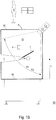
- the containment 9 positioned in an installation room 99 is surrounded by the housing 90 which encloses the working chamber 91.
- a first work glove 1 and a second work glove 2 protrude into the work chamber 91 - as shown in the stretched state.
- These work gloves 1,2 are for Intervention by an authorized operator 8 determined (see Figure 3B ).
- a first camera C1 which has a first detection angle ⁇ 1
- a second camera C2 with its second detection angle ⁇ 2 are provided.
- the first camera C1 monitors the two spatial axes x, y and the second camera C2 the third spatial axis z, the first capture angle ⁇ 1 and the second capture angle ⁇ 2 overlapping so that all areas in the working chamber 91 are captured by the monitoring.
- the recorded states and motion sequences are stored in the computer unit 5 as 3D data and / or video streams.
- a tracking system C1-C2 can be formed by an apparatus that works based on optical systems, laser, radar, ultrasound or infrared technology.
- Each work glove 1, 2 can hold an object 7 , or two work gloves 1, 2 can hold an object 7, for example a tool, together.
- the working chamber 91 there can be temporarily containers 4 which are filled with substances, to be filled with such or to be emptied.
- the computer unit 5 and the signal unit 6 are provided and a monitoring person 8 ' can be assigned. The monitoring person 8 ' will intervene in the process sequence on the containment 9 if necessary.
- the recordings of the tracking system C1-C2 in the computer unit 5 serve both for the continuous three-dimensional localization of the work gloves 1, 2 and the objects 7 guided with them in the xyz coordinate system with a time stamp formed by the three spatial axes x, y, z.
- the spatial positions of the containers 4 within the xyz coordinate system formed with the three spatial axes x, y, z are recorded with a time stamp so that in the event of an accident a non-planned position of a container 4, a possible breakage of a container 4 with it Determine the area of spread and the area of spread of uncontrolled leaking substance.
- Such serious accidents are, for example, broken into splinters Plastic or glass containers and spilled liquid or powder substances.
- the work glove 1 is provided with a large number of systematically distributed marking points P1-P9 .
- the solid body formed by the work glove 1 is recorded as a CAD wire model by the tracking system C1-C2 .
- An object 7 can be guided with the work glove 1 , which object also has marking points Pm-Pn for position detection by means of the tracking system C1-C2 .
- a third camera C3 with its third detection angle ⁇ 3 is installed.
- the first camera C1 with its first detection angle ⁇ 1 monitors the first spatial axis x
- the third camera C3 with its third detection angle ⁇ 3 the third spatial axis z can be useful.
- the tracking system C1-C3 can be used in addition to face recognition FR Detection of the biometric characteristics of an operator 8 positioned at the containment 9 to record the personnel of the operator 8 and / or to determine his authorization for access to the work gloves 1, 2 and only to release it if the answer is yes, as in the two European patent applications nos . 19 405 011.8 and 19 405 012.6 objectified.
- the working chamber 91 If the working chamber 91 is to be decontaminated, it must also be ensured that the work gloves 1, 2 with their sometimes narrow areas, in particular between the fingers, are completely decontaminated, which could not be guaranteed in the turned-in, drooping state. In order utter expansion of the work gloves 1.2, it is practice to insert for the decontamination phase, a stretching device 3 in the respective work glove 1.2.
- the operator is provided 8 with a virtual reality goggles 80, which may be determined, inter alia, the operator 8 more times in accordance with the stored in the computer unit 5 cleaning and disinfection program, the prescribed intensity at the surface cleaning, such as once or Wiping over to be carried out with a minimum contact pressure and indicating that it has been properly fulfilled, e.g. as a color change from red to green when fulfillment has been achieved.
- a virtual reality goggles 80 may be determined, inter alia, the operator 8 more times in accordance with the stored in the computer unit 5 cleaning and disinfection program, the prescribed intensity at the surface cleaning, such as once or Wiping over to be carried out with a minimum contact pressure and indicating that it has been properly fulfilled, e.g. as a color change from red to green when fulfillment has been achieved.
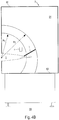
- the work glove 1, 2 protruding into the work chamber 91 can be extended up to a maximum gripping area R1, R2 in the three spatial axes x, y, z . If objects 7 are held by the work gloves 1, 2 , a maximally expanded action area R1 ', R2' results in the three spatial axes x, y, z.
- a three-dimensional or two-dimensional stopband V1, V2 is at least defined, to which a warning area W1, W2 may be adjacent.
- Individual surface sections or the entire floor 92 of the containment 9 can be defined as a restricted area V1, V2 .
- a restricted area V1, V2 and possibly a warning area W1, W2 in front of it can be set up.
- In the restricted area V1, V2 must not be interfered with work gloves 1.2, while in the warning range W1, W2 should not be interfered with work gloves 1.2.
- tracking system C1-C3 also help to establish and monitor when not intervened directly in a stop band V1, but may be inconsistent over a blocking area V1 by about einragenden work glove 1, the laminar flow in a critical extent.
- the virtual reality glasses 80 which the operator 8 wears, are in particular intended to display to the operator 8 the restricted areas V1, V2 and any warning areas W1, W2 defined in the computer unit 5 as graphic elements.
- the signal unit 6 belonging to the arrangement has the purpose of acoustically and / or visually and / or through onto the body of the operator 8 and / or by an operator 8 and / or a monitoring person 8 ' who intervene in the working chamber 91 in the event of impermissible penetration into a restricted area V1, V2 / or to alert the monitoring person 8 'to vibrations acting on them.
- the signal unit 6 serves to prevent critical penetration into a warning area W1, W2 as an approach to a blocked area V1, V2 to report acoustically and / or visually and / or by vibration acting on the body of the operator 8 and / or the monitoring person 8 '.
Abstract
Die Anordnung ist zur Überwachung von Zustand und Bewegungsablauf in einer aseptischen Arbeitskammer (91) eines in einem Aufstellraum (99) stehenden Containments (9) bestimmt. In die Arbeitskammer (91) ragt zumindest ein Arbeitshandschuh (1,2) hinein, wobei der jeweilige Arbeitshandschuh (1,2) in der Arbeitskammer (91) bis zu einem maximalen Greifbereich (R1,R2) in den drei Raumachsen (x,y,z) erstreckbar ist. Die Anordnung umfasst ein Tracking-System (C1-C3), deren Aufzeichnungen zur kontinuierlichen dreidimensionalen Lokalisierung des zumindest einen Arbeitshandschuhs (1,2) dienen und in einer Rechnereinheit (5) abgespeichert sind. In der Arbeitskammer (91) ist zumindest ein dreidimensionaler oder zweidimensionaler Sperrbereich (V1,V2) definiert, an den ein Warnbereich (W1,W2) angrenzen kann. Einzelne Flächenabschnitte oder der gesamte Boden (92) des Containments (9) kann als Sperrbereich (V1,V2) definiert sein. Um Maschinen herum, die in der Arbeitskammer (91) installiert sind und für den Bediener (8) eine Gefahr darstellen, können ein Sperrbereich (V1,V2) und davor eventuell ein Warnbereich (W1,W2) eingerichtet sein. Die Koordinaten von Sperrbereich (V1,V2) und Warnbereich (W1,W2) sind in der Rechnereinheit (5) abgespeichert. In den Sperrbereich (V1,V2) mit dem zumindest einen Arbeitshandschuh (1,2) darf nicht eingegriffen werden; und in den Warnbereich (W1,W2) sollte nicht eingegriffen werden.The arrangement is intended to monitor the state and sequence of movements in an aseptic working chamber (91) of a containment (9) in an installation room (99). At least one work glove (1,2) protrudes into the work chamber (91), the respective work glove (1,2) in the work chamber (91) up to a maximum gripping area (R1, R2) in the three spatial axes (x, y , z) is extensible. The arrangement comprises a tracking system (C1-C3), the recordings of which are used for the continuous three-dimensional localization of the at least one work glove (1,2) and are stored in a computer unit (5). At least one three-dimensional or two-dimensional blocked area (V1, V2), which a warning area (W1, W2) can adjoin, is defined in the working chamber (91). Individual surface sections or the entire floor (92) of the containment (9) can be defined as a restricted area (V1, V2). A restricted area (V1, V2) and possibly a warning area (W1, W2) can be set up around machines that are installed in the working chamber (91) and pose a danger to the operator (8). The coordinates of the restricted area (V1, V2) and warning area (W1, W2) are stored in the computer unit (5). In the restricted area (V1, V2) with the at least one work glove (1,2) must not be reached; and the warning area (W1, W2) should not be intervened.
Description
Die vorliegende Erfindung betrifft eine Anordnung zur Überwachung von Zustand und Bewegungsablauf in einer aseptischen Arbeitskammer eines in einem Aufstellraum stehenden Containments, mit zumindest einem in die Arbeitskammer hineinragenden Arbeitshandschuh. Der jeweilige Arbeitshandschuh ist in der Arbeitskammer bis zu einem maximalen Greifbereich in den drei xyz-Raumachsen erstreckbar. Jeder Arbeitshandschuh könnte jeweils ein Objekt oder zwei Arbeitshandschuhe zusammen könnten ein Objekt halten, wodurch sich ein maximal erweiterter Aktionsbereich in den drei xyz-Raumachsen ergibt. In der Arbeitskammer können sich temporär Behältnisse befinden, die mit Substanzen gefüllt sind, mit solchen zu befüllen oder zu entleeren sind.The present invention relates to an arrangement for monitoring the state and sequence of movements in an aseptic working chamber of a containment standing in an installation room, with at least one work glove protruding into the working chamber. The respective work glove can be extended in the work chamber up to a maximum gripping area in the three xyz spatial axes. Each work glove could hold an object or two work gloves could hold an object together, resulting in a maximally expanded action area in the three xyz spatial axes. In the working chamber there can be temporary containers which are filled with substances, to be filled with such or to be emptied.
Von der Metall+Plastik GmbH, D-78315 Radolfzell/Deutschland, ist die Verwendung von Kameras zum Filmen der Innenräume von Isolatoren zur Überwachung des Geschehens aus verschiedenen Richtungen bekannt. Auch die Firma Nuaire, Plymouth, MN 55447/USA, verwendet Kameras zur kontinuierlichen Aufzeichnung im Isolator (siehe https://www.nuaire.com/learn/general-technicalbulletins/camera-useage-in-a-biosafety-cabinet-pharmacy-isolator; Internetauszug vom 30.09.2019).From Metall + Plastik GmbH, D-78315 Radolfzell / Germany, the use of cameras for filming the interior of insulators to monitor what is happening from different directions is known. Nuaire, Plymouth, MN 55447 / USA, also uses cameras for continuous recording in the isolator (see https://www.nuaire.com/learn/general-technicalbulletins/camera-useage-in-a-biosafety-cabinet-pharmacy -isolator; Internet excerpt from 09/30/2019).
Die Ortner Reinraumtechnik GmbH, A-9500 Villach/Österreich, setzt für den gleichen Zweck eine Gegensprechanlage mit Überwachungskamera ein (siehe https://www.ortner-group.com/produkte/isoline/aseptic-isolator.15f08.php; Internetauszug vom 30.09.2019).Ortner Reinraumtechnik GmbH, A-9500 Villach / Austria, uses an intercom system with surveillance camera for the same purpose (see https://www.ortner-group.com/produkte/isoline/aseptic-isolator.15f08.php; Internet excerpt from 09/30/2019).
Von der Bausch+Ströbel Maschinenfabrik Ilshofen GmbH+Co. KG, D-74532 Ilshofen/Deutschland, ist die Verwendung von Kameras für eine kontinuierliche Aufzeichnung von Abfüllprozessen in Isolatoren bekannt (siehe
Ausgehend vom vorbekannten Stand der Technik liegt der Erfindung die Aufgabe zugrunde, eine weiterentwickelte Anordnung zur Überwachung von Zustand und Bewegungsablauf in einer aseptischen Arbeitskammer eines Containments zu schaffen. Ziel ist es, damit eine sichere Führung für die Handlungen des Bedieners am Containment zu gewährleisten, dennoch fehlerhafte Aktivitäten des Bedieners und Havariefälle rasch zu erkennen und daraus entstandene Verluste zu minimieren.Proceeding from the known prior art, the invention is based on the object of creating a further developed arrangement for monitoring the state and sequence of movements in an aseptic working chamber of a containment. The aim is to ensure safe guidance for the operator's actions at the containment, yet to quickly recognize incorrect operator activities and accidents and to minimize the resulting losses.
Die Anordnung ist zur Überwachung von Zustand und Bewegungsablauf in einer aseptischen Arbeitskammer eines in einem Aufstellraum stehenden Containments konzipiert. In die Arbeitskammer ragt zumindest ein Arbeitshandschuh hinein, wobei der jeweilige Arbeitshandschuh in der Arbeitskammer bis zu einem maximalen Greifbereich in den drei xyz-Raumachsen erstreckbar ist. Erfindungsgemäss umfasst die Anordnung ein Tracking-System, deren Aufzeichnungen zur kontinuierlichen dreidimensionalen Lokalisierung des zumindest einen Arbeitshandschuhs dienen und in einer Rechnereinheit abgespeichert sind. In der Arbeitskammer ist zumindest ein dreidimensionaler oder zweidimensionaler Sperrbereich definiert, an den ein Warnbereich angrenzen kann. Einzelne Flächenabschnitte oder der gesamte Boden des Containments kann als Sperrbereich definiert sein. Um Maschinen herum, die in der Arbeitskammer installiert sind und für den Bediener eine Gefahr darstellen, können ein Sperrbereich und davor eventuell ein Warnbereich eingerichtet sein. Die Koordinaten von Sperrbereich und Warnbereich sind in der Rechnereinheit abgespeichert. In den Sperrbereich mit dem zumindest einen Arbeitshandschuh darf nicht eingegriffen werden; und in den Warnbereich sollte nicht eingegriffen werden.The arrangement is designed to monitor the condition and sequence of movements in an aseptic working chamber of a containment in an installation room. At least one work glove protrudes into the work chamber, the respective work glove in the work chamber being extendable up to a maximum gripping area in the three xyz spatial axes. According to the invention, the arrangement comprises a tracking system, the recordings of which are used for the continuous three-dimensional localization of the at least one work glove and are stored in a computer unit. In the working chamber, at least one three-dimensional or two-dimensional blocked area is defined, which can be bordered by a warning area. Individual surface sections or the entire floor of the containment can be defined as a restricted area. A restricted area and possibly a warning area in front of it can be set up around machines that are installed in the working chamber and pose a danger to the operator. The coordinates of the restricted area and warning area are stored in the computer unit. The at least one work glove must not be used in the restricted area; and no intervention should be made in the warning area.
Nachfolgend werden spezielle Ausführungsformen der Erfindung definiert: Jeder Arbeitshandschuh kann jeweils ein Objekt oder zwei Arbeitshandschuhe zusammen können ein Objekt halten, wodurch sich ein maximal erweiterter Aktionsbereich in den drei xyz-Raumachsen ergibt. Die Aufzeichnungen des Tracking-Systems dienen sowohl zur kontinuierlichen dreidimensionalen Lokalisierung des zumindest einen Arbeitshandschuhs als auch des zumindest einen Objekts. In den Sperrbereich darf auch nicht mit dem Objekt eingegriffen werden, während in den Warnbereich nicht mit dem Objekt eingegriffen werden sollte.Special embodiments of the invention are defined below: Each work glove can hold an object or two work gloves together can hold an object, resulting in a maximally expanded action area in the three xyz spatial axes. The recordings of the tracking system serve both for the continuous three-dimensional localization of the at least one work glove and the at least one object. The object must not be used to intervene in the restricted area, while the object should not be used in the warning area.
In der Rechnereinheit sind die räumlichen Positionen von Arbeitshandschuhen und Objekten innerhalb des mit den drei Raumachsen gebildeten xyz-Koordinatensystems mit Zeitstempel erfasst; und in der Rechnereinheit erfolgt ein Echtzeitvergleich mit den in der Rechnereinheit festgelegten Sperrbereichen und eventuellen Warnbereichen.The spatial positions of work gloves and objects within the xyz coordinate system formed with the three spatial axes are recorded with a time stamp in the computer unit; and in the computer unit there is a real-time comparison with the restricted areas and any warning areas specified in the computer unit.
Temporär können sich in der Arbeitskammer Behältnisse befinden, die mit Substanzen gefüllt sind, mit solchen zu befüllen oder zu entleeren sind. In der Rechnereinheit sind die räumlichen Positionen der Behältnisse innerhalb des mit den drei Raumachsen gebildeten xyz-Koordinatensystems mit Zeitstempel erfasst, um bei einem Havariefall eine nichtplanmässige Position eines Behältnisses, einen eventuellen Bruch eines Behältnisses mit dessen Ausbreitungsbereich und den Ausbreitungsbereich unkontrolliert austretender Substanz festzustellen.There may be temporary containers in the working chamber which are filled with substances, to be filled with such or to be emptied. In the computer unit, the spatial positions of the containers within the xyz coordinate system formed with the three spatial axes are recorded with a time stamp in order to determine, in the event of an accident, an unplanned position of a container, a possible breakage of a container with its area of spread and the area of spread of uncontrolled leaking substance.
Vorteilhaft ist der Bediener mit einer Virtual-Reality-Brille ausgestattet, welche dazu bestimmt ist:
- ihm die in der Rechnereinheit definierten Sperrbereiche und eventuellen Warnbereiche als Grafikelemente anzuzeigen; oder auch zusätzlich
- ihm eine gemäss dem in der Rechnereinheit hinterlegtem Reinigungs- und Desinfektionsprogramm zu reinigenden Fläche anzuzeigen.
- display to him the restricted areas defined in the computer unit and any warning areas as graphic elements; or additionally
- show him an area to be cleaned according to the cleaning and disinfection program stored in the computer unit.
Das Tracking-System umfasst zumindest eine erste Kamera, die einen ersten Erfassungswinkel hat, und eine zweite Kamera, die einen zweiten Erfassungswinkel hat. Die erste Kamera mit ihrem ersten Erfassungswinkel erfasst überwachend die zwei xy-Raumachsen und die zweite Kamera mit ihrem zweiten Erfassungswinkel die dritte z-Raumachse. Der erste Erfassungswinkel und der zweite Erfassungswinkel überlappen sich, so dass alle Bereiche in der Arbeitskammer von der Überwachung erfasst sind. Die erfassten Zustände und Bewegungsabläufe in der Rechnereinheit sind als 3D-Daten und/oder Videostreams abgespeichert.The tracking system comprises at least a first camera that has a first angle of detection and a second camera that has a second angle of detection. The first camera with its first detection angle records the monitoring two xy spatial axes and the second camera with its second detection angle the third z spatial axis. The first detection angle and the second detection angle overlap, so that all areas in the working chamber are covered by the monitoring. The recorded states and movements in the computer unit are stored as 3D data and / or video streams.
Bei grosser räumlicher Ausdehnung der Arbeitskammer sind eine dritte Kamera mit ihrem dritten Erfassungswinkel und - in Abhängigkeit von der Grösse der Arbeitskammer - weitere Kameras mit den jeweiligen Erfassungswinkeln installiert. Dann erfasst die erste Kamera mit ihrem ersten Erfassungswinkel die x-Raumachse, die zweite Kamera mit ihrem zweiten Erfassungswinkel die y-Raumachse und die dritte Kamera mit ihrem dritten Erfassungswinkel die z-Raumachse überwachend. Hierbei überlappen sich die Erfassungswinkel so, dass alle Bereiche in der Arbeitskammer von der Überwachung erfasst sind. Die erfassten Zustände und Bewegungsabläufe in der Rechnereinheit sind als 3D-Daten und/oder Videostreams abgespeichert.In the case of a large spatial expansion of the working chamber, a third camera with its third detection angle and - depending on the size of the working chamber - additional cameras with the respective detection angles are installed. Then the first camera captures the x spatial axis with its first capture angle, the second camera captures the y space axis with its second capture angle and the third camera monitors the z space axis with its third capture angle. The detection angles overlap in such a way that all areas in the working chamber are covered by the monitoring. The recorded states and movements in the computer unit are stored as 3D data and / or video streams.
Eine Signaleinheit ist vorgesehen, welche einen in die Arbeitskammer eingreifenden Bediener und/oder eine Überwachungsperson:
- bei unzulässigem Vordringen in einen Sperrbereich akustisch und/oder optisch und/oder durch auf den Körper des Bedieners und/oder der Überwachungsperson einwirkende Vibration alarmiert; sowie
- bei eingerichteten Warnbereichen bei kritischem Vordringen in einen Warnbereich als Annäherung an einen Sperrbereich akustisch und/oder optisch und/oder durch auf den Körper des Bedieners und/oder der Überwachungsperson einwirkende Vibration zu melden.
- in the event of impermissible penetration into a restricted area, alarms acoustically and / or optically and / or by vibrations acting on the body of the operator and / or the monitoring person; as
- to report acoustically and / or optically and / or through vibrations acting on the body of the operator and / or the monitoring person in the event of critical advance into a warning area as an approach to a restricted area.
In der Rechnereinheit sind weitere Vorschriften definiert, nämlich:
- zum Eingriff in die Arbeitskammer autorisierte Bediener;
- in der Arbeitskammer erlaubte Objekte, z.B. Werkzeuge, und erlaubte, passfähige Bauteile, z.B. Formteile an Füllmaschinen, und der vorschriftsgemässe Einbau solcher Formteile hinsichtlich anlagen-technischer Zuordnung und Positionierung;
- maximal zulässige Geschwindigkeit der in der Arbeitskammer bewegten Arbeitshandschuhe bzw. Objekte; und
- ein Reinigungs- und Desinfektionsprogramm.
- operators authorized to intervene in the working chamber;
- Objects permitted in the working chamber, eg tools, and permitted, suitable components, eg molded parts on filling machines, and the correct installation of such molded parts with regard to system-related assignment and positioning;
- maximum permissible speed of the work gloves or objects moved in the working chamber; and
- a cleaning and disinfection program.
Das Tracking-System ist zusätzlich zur Erkennung der biometrischen Kennzeichen eines am Containment sich positionierten Bedieners ausgestattet.The tracking system is also equipped to recognize the biometric identification of an operator positioned at the containment.
Die Virtual-Reality-Brille zeigt dem Bediener gemäss dem in der Rechnereinheit hinterlegten Reinigungs- und Desinfektionsprogramm die vorgeschriebene Intensität bei der Flächenreinigung, z.B. als ein- oder mehrmaliges mit einem Mindestanpressdruck auszuführendes Überwischen, und deren Erfüllung an, z.B. als Farbumschlag bei erreichter Erfüllung von Rot auf Grün.According to the cleaning and disinfection program stored in the computer unit, the virtual reality glasses show the operator the prescribed intensity for surface cleaning, e.g. as wiping over once or several times with a minimum contact pressure, and their fulfillment, e.g. as a color change when the fulfillment of Red on green.
In einer speziellen Ausführungsform der Überwachungsanordnung ist der Arbeitshandschuh mit systematisch verteilten Markierungspunkten versehen. Anhand dieser Markierungspunkte wird der vom Arbeitshandschuh gebildete Volumenkörper als CAD-Drahtmodell durch das Tracking-System erfasst.In a special embodiment of the monitoring arrangement, the work glove is provided with systematically distributed marking points. Using these marking points, the solid body formed by the work glove is recorded as a CAD wire model by the tracking system.
Das von einem Arbeitshandschuh gehaltene Objekt kann ebenfalls mit systematisch verteilten Markierungspunkten versehen sein. Mittels der Markierungspunkte ist der vom Objekt gebildete Volumenkörper als CAD-Drahtmodell durch das Tracking-System erfassbar.The object held by a work glove can also be provided with systematically distributed marking points. By means of the marking points, the volume body formed by the object can be recorded as a CAD wire model by the tracking system.
Es zeigen:
- Figur 1A
- - die Arbeitskammer eines Containments mit zwei hineinragenden Arbeitshandschuhen, einem gehaltenen Objekt in Gestalt eines Werkzeugs und zwei Kameras, in Draufsicht;
- Figur 1B
- - den Aufbau gemäss
Figur 1A , in Seitenansicht; Figur 2- - einen Arbeitshandschuh mit Werkzeug mit einer Vielzahl systematischer Markierungspunkte zur Erstellung eines CAD-Drahtmodels;
- Figur 3A
- - den Aufbau gemäss
Figur 1A , mit drei Kameras und dem ersten Arbeitshandschuh mit einer Streckvorrichtung, in Draufsicht; - Figur 3B
- - den Aufbau gemäss
Figur 3A , mit einem vor dem Containment stehenden Benutzer, in Seitenansicht; - Figur 4A
- - den Aufbau gemäss
Figur 1A , jeder Arbeitshandschuh mit Werkzeug, zur prinzipiellen Illustration der Greif- und Aktionsbereiche, in Draufsicht; - Figur 4B
- - den Aufbau gemäss
Figur 4A , in Seitenansicht; - Figur 5A
- - den Aufbau gemäss
Figur 1A , der zweite Arbeitshandschuh mit Werkzeug zur prinzipiellen Illustration von Warn- und Verbotsbereichen, in Draufsicht; - Figur 5B
- - den Aufbau gemäss
Figur 5A , in Seitenansicht; - Figur 6A
- - den Aufbau gemäss
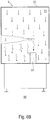
Figur 5A , zur prinzipiellen Illustration mit dem ersten Arbeitshandschuh im Eingriff in den ersten Verbotsbereich, in Draufsicht; und - Figur 6B
- - den Aufbau gemäss
Figur 6A , zur prinzipiellen Illustration gestörter Laminarströmung, in Seitenansicht.
- Figure 1A
- the working chamber of a containment with two work gloves protruding into it, a held object in the form of a tool and two cameras, in plan view;
- Figure 1B
- - the structure according to
Figure 1A , in side view; - Figure 2
- - A work glove with tools with a large number of systematic marking points for creating a CAD wire model;
- Figure 3A
- - the structure according to
Figure 1A , with three cameras and the first work glove with a stretching device, in plan view; - Figure 3B
- - the structure according to
Figure 3A , with a user standing in front of the containment, in side view; - Figure 4A
- - the structure according to
Figure 1A , each work glove with tool, for the basic illustration of the gripping and action areas, in plan view; - Figure 4B
- - the structure according to
Figure 4A , in side view; - Figure 5A
- - the structure according to
Figure 1A , the second work glove with tools for the basic illustration of warning and prohibited areas, in plan view; - Figure 5B
- - the structure according to
Figure 5A , in side view; - Figure 6A
- - the structure according to
Figure 5A , for the basic illustration with the first work glove engaged in the first prohibited area, in plan view; and - Figure 6B
- - the structure according to
Figure 6A , for the principle illustration of disturbed laminar flow, in side view.
Mit Bezug auf die beiliegenden Zeichnungen erfolgt nachstehend die detaillierte Beschreibung der erfindungsgemässen Anordnung zur Überwachung von Zustand und Bewegungsablauf in einer aseptischen Arbeitskammer eines Containments.With reference to the accompanying drawings, the following is a detailed description of the arrangement according to the invention for monitoring the state and sequence of movements in an aseptic working chamber of a containment.
Für die gesamte weitere Beschreibung gilt folgende Festlegung. Sind in einer Figur zum Zweck zeichnerischer Eindeutigkeit Bezugsziffern enthalten und dabei zeichnerisch eindeutig erkennbar ist, dass es sich um "wiederkehrende" Bauteile handelt, aber im unmittelbar zugehörigen Beschreibungstext nicht erläutert, so sei im Interesse der Verkürzung, auf deren Erklärung in vorangehenden Figurenbeschreibungen hingewiesen.The following definition applies to the rest of the description. If a figure contains reference numbers for the purpose of graphic clarity and it can be clearly seen in the drawing that it is a matter of "recurring" components but not explained in the directly associated description text, in the interests of brevity, reference is made to their explanation in the previous figure descriptions.
Das in einem Aufstellraum 99 positionierte Containment 9 ist vom Gehäuse 90 umgeben, welches die Arbeitskammer 91 umschliesst. In die Arbeitskammer 91 ragen - wie im gestreckten Zustand gezeigt - ein erster Arbeitshandschuh 1 und ein zweiter Arbeitshandschuh 2 hinein. Diese Arbeitshandschuhe 1,2 sind zum Eingriff eines berechtigten Bedieners 8 bestimmt (siehe
Ein Tracking-Systems C1-C2 kann anstelle von Kameras C1,C2 von einer Apparatur gebildet werden, die basierend auf optischen Systemen, Laser-, Radar-, Ultraschall- oder Infrarottechnik arbeitet.Instead of cameras C1, C2, a tracking system C1-C2 can be formed by an apparatus that works based on optical systems, laser, radar, ultrasound or infrared technology.
Jeder Arbeitshandschuh 1,2 kann jeweils ein Objekt 7 halten oder zwei Arbeitshandschuhe 1,2 zusammen halten ein Objekt 7, z.B. ein Werkzeug. In der Arbeitskammer 91 können sich temporär Behältnisse 4 befinden, die mit Substanzen gefüllt sind, mit solchen zu befüllen oder zu entleeren sind. Ausserhalb des Containments 9 sind die Rechnereinheit 5 sowie die Signaleinheit 6 vorgesehen und eine Überwachungsperson 8' kann zugeordnet sein. Die Überwachungsperson 8' wird bei Erfordernis in den Prozessablauf am Containment 9 eingreifen.Each
Die Aufzeichnungen des Tracking-Systems C1-C2 in der Rechnereinheit 5 dienen sowohl zur kontinuierlichen dreidimensionalen Lokalisierung der Arbeitshandschuhe 1,2 als auch der mit diesen geführten Objekte 7 in den von den drei Raumachsen x,y,z gebildeten xyz-Koordinatensystems mit Zeitstempel.The recordings of the tracking system C1-C2 in the
In der Rechnereinheit 5 werden auch die räumlichen Positionen der Behältnisse 4 innerhalb des mit den drei Raumachsen x,y,z gebildeten xyz-Koordinatensystems mit Zeitstempel erfasst, um bei einem Havariefall eine nichtplanmässige Position eines Behältnisses 4, einen eventuellen Bruch eines Behältnisses 4 mit dessen Ausbreitungsbereich und den Ausbreitungsbereich unkontrolliert austretender Substanz festzustellen. Solche ernsthaften Havariefälle sind z.B. zu Splittern gebrochene Kunststoff- oder Glasbehälter sowie verschüttete Flüssigkeits- oder Pulversubstanzen.In the
Der Arbeitshandschuh 1 ist mit einer Vielzahl systematisch verteilter Markierungspunkte P1-P9 versehen. Anhand genannter Markierungspunkte P1-P9 wird der vom Arbeitshandschuh 1 gebildete Volumenkörper als CAD-Drahtmodell durch das Tracking-System C1-C2 erfasst. Mit dem Arbeitshandschuh 1 kann ein Objekt 7 geführt werden, welches ebenfalls Markierungspunkte Pm-Pn zur Positionserfassung mittels des Tracking-Systems C1-C2 aufweist.The
Bei grosser räumlicher Ausdehnung der Arbeitskammer 91 ist eine dritte Kamera C3 mit ihrem dritten Erfassungswinkel α3 installiert. Die erste Kamera C1 mit ihrem ersten Erfassungswinkel α1 erfasst überwachend die erste Raumachse x, die zweite Kamera C2 mit ihrem zweiten Erfassungswinkel α2 die zweite Raumachse y und die dritte Kamera C3 mit ihrem dritten Erfassungswinkel α3 die dritte Raumachse z. In Abhängigkeit von der Grösse der Arbeitskammer 91 können weitere Kameras C mit den jeweiligen Erfassungswinkeln α zweckmässig sein. Auch hierbei ist es sinnvoll, dass sich die Erfassungswinkel α1-αn überlappen, um alle Bereiche in der Arbeitskammer 91 von der Überwachung zu erfassen. If the working
In der Rechnereinheit 5 lassen sich Vorschriften definieren, nämlich:
- zum Eingriff in
die Arbeitskammer 91autorisierte Bediener 8; - in
der Arbeitskammer 91erlaubte Objekte 7, z.B. Werkzeuge, und erlaubte, passfähige Bauteile, z.B. Formteile an Füllmaschinen, und der vorschriftsgemässe Einbau solcher Formteile hinsichtlich anlagen-technischer Zuordnung und Positionierung; - maximal zulässige Geschwindigkeit der in
der Arbeitskammer 91bewegten Arbeitshandschuhe Objekte 7; und - ein Reinigungs- und Desinfektionsprogramm.
-
operators 8 authorized to intervene in the workingchamber 91 ; - in the working
chamber 91 permittedobjects 7, for example tools, and permitted, suitable components, for example molded parts on filling machines, and the correct installation of such molded parts with regard to system-technical assignment and positioning; - maximum permissible speed of the
work gloves objects 7 moved in the workingchamber 91 ; and - a cleaning and disinfection program.
Das Tracking-System C1-C3 lässt sich zusätzlich zur Gesichtserkennung FR mit Erfassung der biometrischen Kennzeichen eines am Containment 9 sich positionierten Bedieners 8 ausstatten, um die Personalie des Bedieners 8 zu protokollieren und/oder seine Autorisation für den Zugriff in die Arbeitshandschuhe 1,2 festzustellen und erst bei Bejahung freizugeben, wie in den beiden europäischen Patentanmeldung Nrn.
Bei einer vorzunehmenden Dekontamination der Arbeitskammer 91 ist auch sicherzustellen, dass die Arbeitshandschuhe 1,2 mit ihren teils engen Arealen, insbesondere zwischen den Fingern, vollständig dekontaminiert werden, was im eingestülpten, schlapp hängenden Zustand nicht gewährleistet sein könnte. Zwecks gänzlicher Ausdehnung der Arbeitshandschuhe 1,2 ist es Praxis, für die Dekontaminationsphase eine Streckvorrichtungen 3 in den jeweiligen Arbeitshandschuh 1,2 einzuschieben. If the working
Vorteilhaft ist der Bediener 8 mit einer Virtual-Reality-Brille 80 ausgestattet, welche unter anderem dazu bestimmt sein kann, dem Bediener 8 gemäss dem in der Rechnereinheit 5 hinterlegten Reinigungs- und Desinfektionsprogramm die vorgeschriebene Intensität bei der Flächenreinigung, z.B. als ein- oder mehrmaliges mit einem Mindestanpressdruck auszuführendes Überwischen, und deren ordnungsgemässe Erfüllung anzuzeigen, z.B. als Farbumschlag bei erreichter Erfüllung von Rot auf Grün.Advantageously, the operator is provided 8 with a
Der jeweils in die Arbeitskammer 91 hineinragende Arbeitshandschuh 1,2 ist bis zu einem maximalen Greifbereich R1,R2 in den drei Raumachsen x,y,z erstreckbar. Werden von den Arbeitshandschuhen 1,2 Objekte 7 gehalten, ergibt sich ein maximal erweiterter Aktionsbereich R1',R2' in den drei Raumachsen x,y,z. The
In der Arbeitskammer 91 ist zumindest ein dreidimensionaler oder zweidimensionaler Sperrbereich V1,V2 definiert, an den ein Warnbereich W1,W2 angrenzen kann. Einzelne Flächenabschnitte oder der gesamte Boden 92 des Containments 9 können als Sperrbereich V1,V2 definiert sein. Um Maschinen herum, die in der Arbeitskammer 91 installiert sind und für den Bediener 8 eine Gefahr darstellen, können ein Sperrbereich V1,V2 und davor eventuell ein Warnbereich W1,W2 eingerichtet sein.In the working
Die Koordinaten von Sperrbereich V1,V2 und Warnbereich W1,W2 in den drei Raumachsen x,y,z mit xV1,yV1,zV1 bis xV1',yV1',zV1' beispielhaft für den ersten Sperrbereich V1 und xW1,yW1,zW1 bis xW1',yW1',zW1' beispielhaft für den ersten Warnbereich W1 sind in der Rechnereinheit 5 abgespeichert. In den Sperrbereich V1,V2 darf mit den Arbeitshandschuhen 1,2 nicht eingegriffen werden, während in den Warnbereich W1,W2 mit den Arbeitshandschuhen 1,2 nicht eingegriffen werden sollte. Gleiches gilt für ein Objekt 7, mit dem auch nicht in den Sperrbereich V1,V2 vorgedrungen werden darf, während das für den Warnbereich W1,W2 nicht geschehen sollte. In der Rechnereinheit 5 erfolgt ein Echtzeitvergleich mit den in der Rechnereinheit 5 festgelegten Sperrbereichen V1,V2 und eventuellen Warnbereichen W1,W2. The coordinates of restricted area V1, V2 and warning area W1, W2 in the three spatial axes x, y, z with xV1, yV1, zV1 to xV1 ', yV1', zV1 ' , for example for the first restricted area V1 and xW1, yW1, zW1 to xW1 ', yW1', zW1 ' , for example for the first warning area W1, are stored in the
Mit dem Tracking-System C1-C3 lässt sich auch feststellen und protokollieren, wenn zwar nicht direkt in einen Sperrbereich V1 eingegriffen wird, jedoch über einem Sperrbereich V1 durch einen darüber einragenden Arbeitshandschuh 1 die Laminarströmung möglicherweise in kritischem Ausmass gestört wird.With the tracking system C1-C3 also help to establish and monitor when not intervened directly in a stop band V1, but may be inconsistent over a blocking area V1 by about
Die Virtual-Reality-Brille 80, welche der Bediener 8 trägt, ist insbesondere dazu bestimmt, dem Bediener 8 die in der Rechnereinheit 5 definierten Sperrbereiche V1,V2 und eventuellen Warnbereiche W1,W2 als Grafikelemente anzuzeigen.The
Die zur Anordnung gehörige Signaleinheit 6 hat den Zweck, einen in die Arbeitskammer 91 eingreifenden Bediener 8 und/oder eine Überwachungsperson 8' bei unzulässigem Vordringen in einen Sperrbereich V1,V2 akustisch und/oder optisch und/oder durch auf den Körper des Bedieners 8 und/oder der Überwachungsperson 8' einwirkende Vibration zu alarmieren. The
Sind Warnbereiche W1,W2 eingerichtet, dient die Signaleinheit 6 dazu, das kritische Vordringen in einen Warnbereich W1,W2 als Annäherung an einen Sperrbereich V1,V2 akustisch und/oder optisch und/oder durch auf den Körper des Bedieners 8 und/oder der Überwachungsperson 8' einwirkende Vibration zu melden.If warning areas W1, W2 are set up, the
Claims (13)
Priority Applications (8)
| Application Number | Priority Date | Filing Date | Title |
|---|---|---|---|
| EP19405018.3A EP3815856A1 (en) | 2019-11-04 | 2019-11-04 | Arrangement for monitoring state and movement in an aseptic working chamber of a container |
| JP2022525673A JP2022554332A (en) | 2019-11-04 | 2020-10-22 | Equipment for monitoring the progress of conditions and movements in the containment aseptic working room |
| KR1020227014899A KR20220086593A (en) | 2019-11-04 | 2020-10-22 | Arrangement for monitoring the condition and movement sequence in the aseptic working chamber of the containment unit |
| CN202080074975.2A CN114630736A (en) | 2019-11-04 | 2020-10-22 | Device for monitoring the state and sequence of movements in a sterile working chamber of a protective housing |
| PCT/CH2020/000016 WO2021087628A1 (en) | 2019-11-04 | 2020-10-22 | Arrangement for monitoring state and sequence of movement in an aseptic work chamber of a containment |
| CA3154445A CA3154445A1 (en) | 2019-11-04 | 2020-10-22 | Arrangement for monitoring state and sequence of movement in an aseptic work chamber of a containment |
| US17/774,042 US20230005164A1 (en) | 2019-11-04 | 2020-10-22 | Arrangement for Monitoring State and Sequence of Movement in an Aseptic Work Chamber of a Containment |
| BR112022006240A BR112022006240A2 (en) | 2019-11-04 | 2020-10-22 | Device for monitoring the status and sequence of movement in an aseptic working chamber of a containment |
Applications Claiming Priority (1)
| Application Number | Priority Date | Filing Date | Title |
|---|---|---|---|
| EP19405018.3A EP3815856A1 (en) | 2019-11-04 | 2019-11-04 | Arrangement for monitoring state and movement in an aseptic working chamber of a container |
Publications (1)
| Publication Number | Publication Date |
|---|---|
| EP3815856A1 true EP3815856A1 (en) | 2021-05-05 |
Family
ID=68581735
Family Applications (1)
| Application Number | Title | Priority Date | Filing Date |
|---|---|---|---|
| EP19405018.3A Pending EP3815856A1 (en) | 2019-11-04 | 2019-11-04 | Arrangement for monitoring state and movement in an aseptic working chamber of a container |
Country Status (8)
| Country | Link |
|---|---|
| US (1) | US20230005164A1 (en) |
| EP (1) | EP3815856A1 (en) |
| JP (1) | JP2022554332A (en) |
| KR (1) | KR20220086593A (en) |
| CN (1) | CN114630736A (en) |
| BR (1) | BR112022006240A2 (en) |
| CA (1) | CA3154445A1 (en) |
| WO (1) | WO2021087628A1 (en) |
Cited By (3)
| Publication number | Priority date | Publication date | Assignee | Title |
|---|---|---|---|---|
| EP4144493A1 (en) * | 2021-09-02 | 2023-03-08 | Metall + Plastic GmbH | Insulator device and method of monitoring |
| WO2023030984A1 (en) * | 2021-09-02 | 2023-03-09 | Metall + Plastic Gmbh | Isolator apparatus and method for monitoring |
| WO2023104707A1 (en) | 2021-12-06 | 2023-06-15 | Fresenius Kabi Austria Gmbh | System and method for monitoring critical pharmaceutical operations |
Families Citing this family (1)
| Publication number | Priority date | Publication date | Assignee | Title |
|---|---|---|---|---|
| WO2024026139A1 (en) * | 2022-07-29 | 2024-02-01 | The University Of North Carolina At Chapel Hill | Methods, systems, and computer readable media for automated assessment of aseptic technique of compounding in a compounding hood |
Citations (3)
| Publication number | Priority date | Publication date | Assignee | Title |
|---|---|---|---|---|
| DE102012007242A1 (en) * | 2012-03-09 | 2013-09-12 | Fraunhofer-Gesellschaft zur Förderung der angewandten Forschung e.V. | Monitoring system for ensuring cooperation between worker and robot in human robot cooperation system, has control unit that controls robot using position of worker and region crossed by worker and robot in and/or from danger area |
| US20160376044A9 (en) * | 2009-02-26 | 2016-12-29 | Christopher Procyshyn | Robotic filling systems and methods |
| WO2019173678A1 (en) * | 2018-03-09 | 2019-09-12 | Siemens Aktiengesellschaft | Optimal hand pose tracking using a flexible electronics-based sensing glove and machine learning |
Family Cites Families (7)
| Publication number | Priority date | Publication date | Assignee | Title |
|---|---|---|---|---|
| JP5602512B2 (en) * | 2010-06-21 | 2014-10-08 | 三洋電機株式会社 | Closed space working system |
| US20130076898A1 (en) * | 2011-08-01 | 2013-03-28 | Richard Philippe | Apparatus, systems, and methods for tracking medical products using an imaging unit |
| EP2913042B1 (en) * | 2012-10-25 | 2019-10-02 | Yuyama Mfg. Co., Ltd. | Co-infusion device |
| WO2015042120A1 (en) * | 2013-09-18 | 2015-03-26 | Richard Awdeh | Surgical navigation system and method |
| JP6799950B2 (en) * | 2016-06-15 | 2020-12-16 | Ntn株式会社 | Work equipment and double-armed work equipment |
| GB201709199D0 (en) * | 2017-06-09 | 2017-07-26 | Delamont Dean Lindsay | IR mixed reality and augmented reality gaming system |
| GB2586045B (en) * | 2019-07-31 | 2023-09-13 | Soletanche Freyssinet Sas | Surveying and dismantling system |
-
2019
- 2019-11-04 EP EP19405018.3A patent/EP3815856A1/en active Pending
-
2020
- 2020-10-22 KR KR1020227014899A patent/KR20220086593A/en unknown
- 2020-10-22 WO PCT/CH2020/000016 patent/WO2021087628A1/en active Application Filing
- 2020-10-22 US US17/774,042 patent/US20230005164A1/en active Pending
- 2020-10-22 JP JP2022525673A patent/JP2022554332A/en active Pending
- 2020-10-22 BR BR112022006240A patent/BR112022006240A2/en unknown
- 2020-10-22 CN CN202080074975.2A patent/CN114630736A/en active Pending
- 2020-10-22 CA CA3154445A patent/CA3154445A1/en active Pending
Patent Citations (3)
| Publication number | Priority date | Publication date | Assignee | Title |
|---|---|---|---|---|
| US20160376044A9 (en) * | 2009-02-26 | 2016-12-29 | Christopher Procyshyn | Robotic filling systems and methods |
| DE102012007242A1 (en) * | 2012-03-09 | 2013-09-12 | Fraunhofer-Gesellschaft zur Förderung der angewandten Forschung e.V. | Monitoring system for ensuring cooperation between worker and robot in human robot cooperation system, has control unit that controls robot using position of worker and region crossed by worker and robot in and/or from danger area |
| WO2019173678A1 (en) * | 2018-03-09 | 2019-09-12 | Siemens Aktiengesellschaft | Optimal hand pose tracking using a flexible electronics-based sensing glove and machine learning |
Non-Patent Citations (1)
| Title |
|---|
| JORGE USABIAGA ET AL: "Global hand pose estimation by multiple camera ellipse tracking", MACHINE VISION AND APPLICATIONS, SPRINGER, BERLIN, DE, vol. 21, no. 1, 24 May 2008 (2008-05-24), pages 1 - 15, XP019755536, ISSN: 1432-1769 * |
Cited By (3)
| Publication number | Priority date | Publication date | Assignee | Title |
|---|---|---|---|---|
| EP4144493A1 (en) * | 2021-09-02 | 2023-03-08 | Metall + Plastic GmbH | Insulator device and method of monitoring |
| WO2023030984A1 (en) * | 2021-09-02 | 2023-03-09 | Metall + Plastic Gmbh | Isolator apparatus and method for monitoring |
| WO2023104707A1 (en) | 2021-12-06 | 2023-06-15 | Fresenius Kabi Austria Gmbh | System and method for monitoring critical pharmaceutical operations |
Also Published As
| Publication number | Publication date |
|---|---|
| CA3154445A1 (en) | 2021-05-14 |
| WO2021087628A1 (en) | 2021-05-14 |
| BR112022006240A2 (en) | 2022-06-21 |
| JP2022554332A (en) | 2022-12-28 |
| CN114630736A (en) | 2022-06-14 |
| US20230005164A1 (en) | 2023-01-05 |
| KR20220086593A (en) | 2022-06-23 |
Similar Documents
| Publication | Publication Date | Title |
|---|---|---|
| EP3815856A1 (en) | Arrangement for monitoring state and movement in an aseptic working chamber of a container | |
| DE102005063217B4 (en) | Method for configuring a monitoring device for monitoring a room area and corresponding monitoring device | |
| DE102012211071B3 (en) | Interaction between a mobile robot and an alarm system | |
| EP2023160B1 (en) | 3D room surveillance with configuration mode for determining the protection fields | |
| EP3200122B1 (en) | Optoelectronic sensor and method for secure detection of objects of at least a certain size | |
| EP3578320B1 (en) | Configuring a hazardous area monitored by a 3d sensor | |
| EP2048557A1 (en) | Optoelectronic sensor and mobile device and configuration method | |
| DE10249786A1 (en) | Referencing method for relating robot to workpiece, in medical applications, by relating reference point using x and y position data obtained from at least two images picked up using camera mounted on robot arm | |
| EP3195256B1 (en) | Method and apparatus for identifying structural elements of a projected structural pattern in camera images | |
| DE102013220107A1 (en) | Method for guiding and / or controlling assembly and commissioning processes to be carried out at a workstation | |
| EP3324362B1 (en) | Method and device for commissioning a multi-axis system | |
| EP2053538A1 (en) | Securing a surveillance area and visual support for automatic processing | |
| DE102012014057A1 (en) | Method for monitoring work area to detect whether worker enters into danger zone in manufacturing facility, involves observing work area by camera, and generating signal associated with predetermined event during occurrence of event | |
| DE102018101162B4 (en) | Measuring system and method for extrinsic calibration | |
| EP2819109A1 (en) | Apparatus comprising an optoelectronic 3D-sensor and method for recognising objects | |
| EP3323565B1 (en) | Method and device for commissioning a multiple axis system | |
| DE102008052579A1 (en) | Safety system for working device, comprises unit and camera which is arranged at unit, where movement of unit is monitored by camera, based on degree of freedom of unit | |
| EP3203262B1 (en) | Optoelectronic device for securing a source of danger | |
| DE102017213658A1 (en) | Handling arrangement with a handling device for performing at least one work step and method and computer program | |
| DE102015114463A1 (en) | Safety device and safety procedures | |
| DE102015012732A1 (en) | System and method for controlling, in particular for commissioning, a production plant | |
| DE102019127826B4 (en) | Safe optoelectronic sensor and method for securing a surveillance area | |
| EP2818824B1 (en) | Apparatus comprising an optoelectronic 3D-sensor and method for recognising objects | |
| EP3427904B1 (en) | Assembly with a manipulator and a limiting device for limiting the working space | |
| AT524080A1 (en) | Device and method for detecting speeds of arm segments of a robot |
Legal Events
| Date | Code | Title | Description |
|---|---|---|---|
| PUAI | Public reference made under article 153(3) epc to a published international application that has entered the european phase |
Free format text: ORIGINAL CODE: 0009012 |
|
| STAA | Information on the status of an ep patent application or granted ep patent |
Free format text: STATUS: THE APPLICATION HAS BEEN PUBLISHED |
|
| AK | Designated contracting states |
Kind code of ref document: A1 Designated state(s): AL AT BE BG CH CY CZ DE DK EE ES FI FR GB GR HR HU IE IS IT LI LT LU LV MC MK MT NL NO PL PT RO RS SE SI SK SM TR |
|
| STAA | Information on the status of an ep patent application or granted ep patent |
Free format text: STATUS: REQUEST FOR EXAMINATION WAS MADE |
|
| 17P | Request for examination filed |
Effective date: 20210819 |
|
| RBV | Designated contracting states (corrected) |
Designated state(s): AL AT BE BG CH CY CZ DE DK EE ES FI FR GB GR HR HU IE IS IT LI LT LU LV MC MK MT NL NO PL PT RO RS SE SI SK SM TR |