EP3815804A1 - Method of emulsion concentration optimization for cold continuous rolling mill set - Google Patents
Method of emulsion concentration optimization for cold continuous rolling mill set Download PDFInfo
- Publication number
- EP3815804A1 EP3815804A1 EP19865518.5A EP19865518A EP3815804A1 EP 3815804 A1 EP3815804 A1 EP 3815804A1 EP 19865518 A EP19865518 A EP 19865518A EP 3815804 A1 EP3815804 A1 EP 3815804A1
- Authority
- EP
- European Patent Office
- Prior art keywords
- stand
- calculating
- emulsion
- emulsion concentration
- rolling mill
- Prior art date
- Legal status (The legal status is an assumption and is not a legal conclusion. Google has not performed a legal analysis and makes no representation as to the accuracy of the status listed.)
- Granted
Links
Images


Classifications
-
- B—PERFORMING OPERATIONS; TRANSPORTING
- B21—MECHANICAL METAL-WORKING WITHOUT ESSENTIALLY REMOVING MATERIAL; PUNCHING METAL
- B21B—ROLLING OF METAL
- B21B37/00—Control devices or methods specially adapted for metal-rolling mills or the work produced thereby
-
- B—PERFORMING OPERATIONS; TRANSPORTING
- B21—MECHANICAL METAL-WORKING WITHOUT ESSENTIALLY REMOVING MATERIAL; PUNCHING METAL
- B21B—ROLLING OF METAL
- B21B45/00—Devices for surface or other treatment of work, specially combined with or arranged in, or specially adapted for use in connection with, metal-rolling mills
- B21B45/02—Devices for surface or other treatment of work, specially combined with or arranged in, or specially adapted for use in connection with, metal-rolling mills for lubricating, cooling, or cleaning
- B21B45/0239—Lubricating
- B21B45/0242—Lubricants
-
- B—PERFORMING OPERATIONS; TRANSPORTING
- B21—MECHANICAL METAL-WORKING WITHOUT ESSENTIALLY REMOVING MATERIAL; PUNCHING METAL
- B21B—ROLLING OF METAL
- B21B37/00—Control devices or methods specially adapted for metal-rolling mills or the work produced thereby
- B21B37/58—Roll-force control; Roll-gap control
- B21B37/62—Roll-force control; Roll-gap control by control of a hydraulic adjusting device
-
- B—PERFORMING OPERATIONS; TRANSPORTING
- B21—MECHANICAL METAL-WORKING WITHOUT ESSENTIALLY REMOVING MATERIAL; PUNCHING METAL
- B21B—ROLLING OF METAL
- B21B27/00—Rolls, roll alloys or roll fabrication; Lubricating, cooling or heating rolls while in use
- B21B27/06—Lubricating, cooling or heating rolls
- B21B27/10—Lubricating, cooling or heating rolls externally
-
- B—PERFORMING OPERATIONS; TRANSPORTING
- B21—MECHANICAL METAL-WORKING WITHOUT ESSENTIALLY REMOVING MATERIAL; PUNCHING METAL
- B21B—ROLLING OF METAL
- B21B37/00—Control devices or methods specially adapted for metal-rolling mills or the work produced thereby
- B21B37/007—Control for preventing or reducing vibration, chatter or chatter marks
-
- B—PERFORMING OPERATIONS; TRANSPORTING
- B21—MECHANICAL METAL-WORKING WITHOUT ESSENTIALLY REMOVING MATERIAL; PUNCHING METAL
- B21B—ROLLING OF METAL
- B21B45/00—Devices for surface or other treatment of work, specially combined with or arranged in, or specially adapted for use in connection with, metal-rolling mills
- B21B45/02—Devices for surface or other treatment of work, specially combined with or arranged in, or specially adapted for use in connection with, metal-rolling mills for lubricating, cooling, or cleaning
- B21B45/0239—Lubricating
- B21B45/0245—Lubricating devices
- B21B45/0248—Lubricating devices using liquid lubricants, e.g. for sections, for tubes
- B21B45/0251—Lubricating devices using liquid lubricants, e.g. for sections, for tubes for strips, sheets, or plates
-
- B—PERFORMING OPERATIONS; TRANSPORTING
- B21—MECHANICAL METAL-WORKING WITHOUT ESSENTIALLY REMOVING MATERIAL; PUNCHING METAL
- B21B—ROLLING OF METAL
- B21B1/00—Metal-rolling methods or mills for making semi-finished products of solid or profiled cross-section; Sequence of operations in milling trains; Layout of rolling-mill plant, e.g. grouping of stands; Succession of passes or of sectional pass alternations
- B21B1/22—Metal-rolling methods or mills for making semi-finished products of solid or profiled cross-section; Sequence of operations in milling trains; Layout of rolling-mill plant, e.g. grouping of stands; Succession of passes or of sectional pass alternations for rolling plates, strips, bands or sheets of indefinite length
- B21B2001/221—Metal-rolling methods or mills for making semi-finished products of solid or profiled cross-section; Sequence of operations in milling trains; Layout of rolling-mill plant, e.g. grouping of stands; Succession of passes or of sectional pass alternations for rolling plates, strips, bands or sheets of indefinite length by cold-rolling
-
- B—PERFORMING OPERATIONS; TRANSPORTING
- B21—MECHANICAL METAL-WORKING WITHOUT ESSENTIALLY REMOVING MATERIAL; PUNCHING METAL
- B21B—ROLLING OF METAL
- B21B37/00—Control devices or methods specially adapted for metal-rolling mills or the work produced thereby
- B21B2037/002—Mass flow control
-
- B—PERFORMING OPERATIONS; TRANSPORTING
- B21—MECHANICAL METAL-WORKING WITHOUT ESSENTIALLY REMOVING MATERIAL; PUNCHING METAL
- B21B—ROLLING OF METAL
- B21B2261/00—Product parameters
- B21B2261/20—Temperature
-
- B—PERFORMING OPERATIONS; TRANSPORTING
- B21—MECHANICAL METAL-WORKING WITHOUT ESSENTIALLY REMOVING MATERIAL; PUNCHING METAL
- B21B—ROLLING OF METAL
- B21B45/00—Devices for surface or other treatment of work, specially combined with or arranged in, or specially adapted for use in connection with, metal-rolling mills
- B21B45/02—Devices for surface or other treatment of work, specially combined with or arranged in, or specially adapted for use in connection with, metal-rolling mills for lubricating, cooling, or cleaning
- B21B45/0266—Measuring or controlling thickness of liquid films
Definitions
- the present invention belongs to the field of cold continuous rolling, and in particular relates to a method of emulsion concentration optimization for a cold continuous rolling mill set for achieving vibration suppression.
- emulsion concentration plays a vital role in the lubrication status of the roll gap of each stand of the cold continuous rolling mill set.
- the lubrication status of the roll gap directly affects the occurrence of vibration defects of the rolling mill.
- the friction coefficient is too small, which is likely to cause slip in the rolling process and leads to self-excited vibration of the rolling mill.
- the roll gap is in an under-lubricated status, the average oil film thickness in the roll gap is less than the required minimum value, which is likely to cause the oil film in the roll gap to crack during the rolling process and leads to the sharp increase of the friction coefficient, thus changing the rolling pressure, causing the periodic fluctuation of the system stiffness and causing the self-excited vibration of the rolling mill as well.
- the site generally relies on the speed of the rolling mill to suppress the occurrence of vibration defects, but this operation restricts the improvement of the production efficiency of the cold continuous rolling mill set and seriously affects the economic benefits of the enterprise.
- the Chinese invention patent with the authorized announcement number of CN 103544340 B and the authorized announcement date of March 2, 2016 discloses a "Method for Setting Emulsion Concentration in Extremely Thin Strip Rolling of Five-stand Cold Continuous Rolling Mill Set".
- the method for setting emulsion concentration includes the following steps executed by a computer: 1) acquiring the main equipment of the mill set, the characteristics of the strip to be rolled, the main rolling process and the process lubrication system parameters; 2) defining relevant process parameters; 3) calculating the roll bending force and roll shifting amount; 4) assigning values to relevant search process parameters; 5) calculating concentration process parameters; 6) calculating the search process speed of the maximum rolling speed; 7) calculating the friction coefficient of each stand under the current conditions; 8) calculating the rolling force, rolling power, slip factor, thermal slip injury index and vibration coefficient of each stand under the current conditions; 9) calculating the thermal crown of the work roll of each stand; 10) calculating the outlet plate shape and the forced-contact width; and 11) obtaining and outputting
- the setting of emulsion concentration directly determines the lubrication status of the roll gap of each stand of the cold continuous rolling mill set, and can be used as the main process control means to suppress the vibration of the rolling mill.
- the technical problem to be solved by the invention is to provide a method of emulsion concentration optimization for a cold continuous rolling mill set for achieving vibration suppression.
- the method changes the previous mode of constant concentration control of the emulsion in each stand, takes the concentration of the emulsion in each stand as a variable to be optimized, and carries out comprehensive optimization control on emulsion concentration.
- the lubrication status of roll gaps in each stand is optimized through the reasonable proportion of emulsion concentration in each stand, thus achieving the purposes of suppressing vibration of the rolling mill, improving product quality and production efficiency, and bringing economic benefits to enterprises.
- the technical solution of the invention is to provide a method of emulsion concentration optimization for a cold continuous rolling mill set for achieving vibration suppression, wherein the method includes the following steps:
- the critical rolling process parameters of the strip material at least include: the inlet thickness h 0 i of each stand; the outlet thickness h 1 i of each stand; the width B of the strip steel; the inlet speed v 0 i of each stand; the outlet speed v 1 i ; of each stand; the inlet temperature T 1 Inlet ; the resistance to deformation K i of the strip steel of each stand; the rolling pressure P i of each stand; the back tension T 0 i of each stand; the front tension T 1 i , of each stand; the concentration influence coefficient k c of the emulsion; the viscosity compression coefficient ⁇ of a lubricant; the density p of the strip steel; the specific heat capacity S of the strip steel; the flow rate w of the emulsion; the temperature T c of the emulsion; and the mechanical equivalent of heat J .
- ⁇ i ⁇ h i R i ′
- R i ' is the flattening radius of the work roll of the i th stand, and is a process value in rolling pressure calculation.
- ⁇ i h 0 i + h 1 i 2 h 0 i ⁇ k c ⁇ 3 ⁇ 0 i v ri + v 0 i ⁇ i 1 ⁇ e ⁇ ⁇ K i ⁇ T 0 i h 0 i ⁇ B ⁇ k rg ⁇ 1 + K rs ⁇ Ra ir 0 ⁇ e ⁇ B Li ⁇ L i , wherein h 0 i is the inlet thickness of each stand, h 1 i is the outlet thickness of each stand, k c is the emulsion concentration influence coefficient, ⁇ is the viscosity compression coefficient of the lubricant, K i is the resistance to deformation of the strip steel of each stand, ⁇ 0 i is the dynamic viscosity of the emulsion in the roll gap of each stand, v
- the invention has the following advantages:
- a 1730 cold continuous rolling mill set of a cold rolling plant is taken as an example.
- the application process of the method of emulsion concentration optimization for a cold continuous rolling mill set for achieving vibration suppression is described in detail.
- the relevant parameters are determined in turn. Then the parameters are substituted into corresponding formulas for calculation, and the desired optimal emulsion concentration set value C i y is determined or obtained. Finally, the emulsion concentration of each stand is controlled according to the determined optimal emulsion concentration set value, and the comprehensive optimization control is carried out to achieve suppressing the vibration of the rolling mill.
- the acquired apparatus characteristic parameters of a cold continuous rolling mill set mainly include:
- the outlet temperature T i of the strip steel of each stand is calculated according to the sub-steps shown in the Fig.3 .
- i is set to 1.
- j is set to 2.
- step (m) whether the emulsion concentration C i exceeds the range of the feasible region is determined, if yes, the step (n) is performed; if no, the step (g) is performed.
- the optimal emulsion concentration set value C i y 4.2 4.2 4.5 4.6 4.3 % is outputted, wherein C i y is the value of C i when the calculated value of F(X) is minimum in the feasible region.
- control system of the cold continuous rolling mill set adjusts and controls the emulsion concentration of each stand respectively according to the optimal emulsion concentration set value obtained in the step (n).
- the technical solution of the invention changes the mode in the prior art that the emulsion in each stand adopts constant concentration control, takes the concentration of the emulsion in each stand as a variable to be optimized, and carries out comprehensive optimization control on the emulsion concentration, thus achieving suppressing the vibration of the rolling mill.
- the method of the invention can be widely used in the field of controlling emulsion concentration of the cold continuous rolling mill set.
Landscapes
- Engineering & Computer Science (AREA)
- Mechanical Engineering (AREA)
- Metal Rolling (AREA)
- Control Of Metal Rolling (AREA)
- Feedback Control In General (AREA)
Abstract
Description
- The present invention belongs to the field of cold continuous rolling, and in particular relates to a method of emulsion concentration optimization for a cold continuous rolling mill set for achieving vibration suppression.
- As an important process parameter in the process lubrication system, emulsion concentration plays a vital role in the lubrication status of the roll gap of each stand of the cold continuous rolling mill set.
- At the same time, the lubrication status of the roll gap directly affects the occurrence of vibration defects of the rolling mill.
- If the roll gap is in an over-lubricated status, the friction coefficient is too small, which is likely to cause slip in the rolling process and leads to self-excited vibration of the rolling mill. If the roll gap is in an under-lubricated status, the average oil film thickness in the roll gap is less than the required minimum value, which is likely to cause the oil film in the roll gap to crack during the rolling process and leads to the sharp increase of the friction coefficient, thus changing the rolling pressure, causing the periodic fluctuation of the system stiffness and causing the self-excited vibration of the rolling mill as well.
- In the past, the site generally relies on the speed of the rolling mill to suppress the occurrence of vibration defects, but this operation restricts the improvement of the production efficiency of the cold continuous rolling mill set and seriously affects the economic benefits of the enterprise.
- The Chinese invention patent with the authorized announcement number of
CN 103544340 B and the authorized announcement date of March 2, 2016 discloses a "Method for Setting Emulsion Concentration in Extremely Thin Strip Rolling of Five-stand Cold Continuous Rolling Mill Set". The method for setting emulsion concentration includes the following steps executed by a computer: 1) acquiring the main equipment of the mill set, the characteristics of the strip to be rolled, the main rolling process and the process lubrication system parameters; 2) defining relevant process parameters; 3) calculating the roll bending force and roll shifting amount; 4) assigning values to relevant search process parameters; 5) calculating concentration process parameters; 6) calculating the search process speed of the maximum rolling speed; 7) calculating the friction coefficient of each stand under the current conditions; 8) calculating the rolling force, rolling power, slip factor, thermal slip injury index and vibration coefficient of each stand under the current conditions; 9) calculating the thermal crown of the work roll of each stand; 10) calculating the outlet plate shape and the forced-contact width; and 11) obtaining and outputting the optimum proportion concentration. It can be seen that the patent aims at improving the rolling speed, ensuring the rolling efficiency, and avoiding slipping, thermal slip injury and vibration, so as to ensure the outlet plate shape of the final stand and the minimum forced-contact width at the work roll end. - Through research, it is found that under the premise of determining the process parameters such as rolling schedule, roll process, emulsion flow rate and initial temperature, the setting of emulsion concentration directly determines the lubrication status of the roll gap of each stand of the cold continuous rolling mill set, and can be used as the main process control means to suppress the vibration of the rolling mill.
- However, at present, there has not been a report providing the technical solution of suppressing the vibration of the rolling mill by changing the previous mode of constant concentration control of an emulsion in each stand and taking the concentration of the emulsion in each stand as a variable to be optimized.
- The technical problem to be solved by the invention is to provide a method of emulsion concentration optimization for a cold continuous rolling mill set for achieving vibration suppression. The method changes the previous mode of constant concentration control of the emulsion in each stand, takes the concentration of the emulsion in each stand as a variable to be optimized, and carries out comprehensive optimization control on emulsion concentration. The lubrication status of roll gaps in each stand is optimized through the reasonable proportion of emulsion concentration in each stand, thus achieving the purposes of suppressing vibration of the rolling mill, improving product quality and production efficiency, and bringing economic benefits to enterprises.
- The technical solution of the invention is to provide a method of emulsion concentration optimization for a cold continuous rolling mill set for achieving vibration suppression, wherein the method includes the following steps:
- (a) acquiring apparatus characteristic parameters of a cold continuous rolling mill set;
- (b) acquiring critical rolling process parameters of a strip material;
- (c) acquiring process parameters involved in the process of emulsion concentration optimization;
- (d) setting an initial set value F 0 =1.0×10¹⁰ of an emulsion concentration comprehensive optimization target function for a cold continuous rolling mill set for achieving vibration suppression;
- (e) calculating a bite angle α i of each stand;
- (f) calculating a vibration determination index reference value ξ 0i of each stand;
- (g) setting an emulsion concentration Ci of each stand;
- (h) calculating the outlet temperature Ti of a strip steel of each stand;
- (i) calculating the dynamic viscosity η 0i of an emulsion in a roll gap of each stand;
- (j) calculating an oil film thickness ξi in the roll gap of each stand;
- (k) calculating the emulsion concentration comprehensive optimization target function F(X);
- (1) determining whether the inequation F(X) <F0 is established, if yes, then setting

- (m) determining whether the emulsion concentration Ci exceeds the range of a feasible region, if yes, turning to step (n); if no, turning to the step (g); wherein the feasible region refers to a region from 0 to the maximum emulsion concentration allowed by an apparatus, and wherein the allowed emulsion concentration of the apparatus is usually within 10%, and 0∼10% can be set as the feasible range;
- (n) outputting the optimal emulsion concentration set value


- (o) adjusting and controlling the emulsion concentration of each stand according to the optimal emulsion concentration set value

- (f1) calculating an over-lubricated oil film thickness critical value

- it is assumed that when

- calculating to obtain


and
- wherein T 0i is the back tension of each stand, T 1i is the front tension of each stand, and Pi is the rolling pressure of each stand,
- according to the relationship between the friction coefficient and the oil film thickness: ui=ai +bi · e Bi ·ξi , wherein ai is the liquid friction influence coefficient, bi is the dry friction influence coefficient, and Bi is the friction coefficient attenuation index, the over-lubricated oil film thickness critical value


- it is assumed that when
- (f2) calculating an under-lubricated oil film thickness critical value

- it is assumed that when


- and the under-lubricated oil film thickness critical value


- it is assumed that when
- (f3) calculating the vibration determination index reference value ξ 0i of each stand as follows:

- (h1) calculating the outlet temperature T 1 of the first stand:


- (h2) setting i to 1;
- (h3) setting the temperature of the first section of strip steel behind the outlet of the ith stand to Ti, 1, i.e., Ti , 1=Ti ;
- (h4) setting j to 2;
- (h5) the relationship between the temperature of the j th section and the temperature of the j-1th section satisfies the following equation:

- (h6) determining whether the inequation j < m is established, if yes, then setting j=j+1 and turning to the step (h5); if no, turning to step (h7);
- (h7) obtaining the temperature Ti,m of the m th section via iterative calculation;
- (h8) calculating the inlet temperature Ti+1 Inlet of the i+1th stand:

- (h9) calculating the outlet temperature T i+1 of the i+1th stand;

- (h10) determining whether the inequation i<n is established, if yes, setting i=i+1 and turning to the step (h3); if no, turning to step (h11); and
- (h11) obtaining the outlet temperature Ti of each stand.
- Specifically, apparatus characteristic parameters of the cold continuous rolling mill set at least include:
the radius Ri of a work roll of each stand; the surface linear speed vri of a roll of each stand; the original roughness Ra ir0 of a work roll of each stand; the roughness attenuation coefficient BL of a work roll; the distance l between stands; and rolling kilometers Li of a work roll of each stand after roll change; wherein i = 1, 2,..., n; i represents the ordinal number of the stand of the cold continuous rolling mill set, and n is the total number of the stands. - Specifically, the critical rolling process parameters of the strip material at least include:
the inlet thickness h 0i of each stand; the outlet thickness h 1i of each stand; the width B of the strip steel; the inlet speed v 0i of each stand; the outlet speed v 1i; of each stand; the inlet temperature T1 Inlet ; the resistance to deformation Ki of the strip steel of each stand; the rolling pressure Pi of each stand; the back tension T 0i of each stand; the front tension T 1i , of each stand; the concentration influence coefficient kc of the emulsion; the viscosity compression coefficient θ of a lubricant; the density p of the strip steel; the specific heat capacity S of the strip steel; the flow rate w of the emulsion; the temperature Tc of the emulsion; and the mechanical equivalent of heat J. - Specifically, the process parameters involved in the process of emulsion concentration optimization at least include: the over-lubricated oil film thickness critical value


- Further, the calculation formula for calculating the bite angle αi , of each stand is as follows:

- Further, the calculation formula for calculating the dynamic viscosity η 0i of the emulsion in the roll gap of each stand is as follows:

- Further, the calculation formula for calculating the oil film thickness ξi in the roll gap of each stand is as follows:

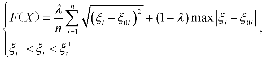
- Further, the emulsion concentration comprehensive optimization target function is calculated according to the following formula:

- In the disclosure, as long as the execution of the next step is not conditional on the result of the previous step, it is not necessary to proceed according to the above order, unless the execution of the next step depends on the previous step.
- Compared with the prior art, the invention has the following advantages:
- 1. The lubricated status of roll gaps in each stand is optimized through reasonable proportion of the emulsion concentration of each stand, thus achieving the purposes of suppressing vibration of the rolling mill, and improving product quality and production efficiency.
- 2. As a result of a large number of field tests and theoretical research, based on the apparatus characteristics and rolling process features of the cold continuous rolling mill set, a method of emulsion concentration optimization for a cold continuous rolling mill set for achieving vibration suppression is put forward. The method realizes the optimal ratio of emulsion concentration for each stand of the cold continuous rolling mill set, achieves suppressing vibration of the rolling mill and improving product quality and production efficiency, and brings great economic benefits to enterprises.
-
-
Fig. 1 is a schematic flow diagram of the general technical solutions according to the present invention; -
Fig. 2 is a schematic diagram of the calculation process of the reference value of the vibration determination index according to the present invention; and -
Fig. 3 is a schematic diagram of the calculation process of the strip steel outlet temperature of each stand according to the present invention. - The invention will be further described below in conjunction with the accompany drawings and embodiments.
- In order to further explain the application process of the related technologies mentioned in the invention, a 1730 cold continuous rolling mill set of a cold rolling plant is taken as an example. The application process of the method of emulsion concentration optimization for a cold continuous rolling mill set for achieving vibration suppression is described in detail.
- At first, according to the various steps shown in
Fig. 1 , the relevant parameters are determined in turn. Then the parameters are substituted into corresponding formulas for calculation, and the desired optimal emulsion concentration set value
- Specifically, in the step (a), the acquired apparatus characteristic parameters of a cold continuous rolling mill set mainly include:
- the radius of a work roll of each stand: Ri ={210, 212, 230, 230, 228} mm;
- the surface linear speed of a roll of each stand: vri ={180, 320, 500, 800,11 50} m/min;
- the original roughness of a work roll of each stand: Ra ir0={1.0,1.0,0.8,0.8,1.0} um;
- the roughness attenuation coefficient of the work roll: BL=0.01;
- the distance between stands: l=2700mm ; and
- the rolling kilometers of a work roll of each stand after roll change: L i={100,110,230,180,90}km; wherein i=1,2,...,n; i represents the ordinal number of the stand of the cold continuous rolling mill set; and n=5, which is the total number of the stands, the same below;
- subsequently, in the step (b), the acquired critical rolling process parameters of the strip material mainly include:
- the inlet thickness of each stand: h 0i ,={2.0,1.14,0.63,0.43,0.28}mm;
- the outlet thickness of each stand: h 1i ={1.14, 0.63, 0.43,0.28,0.18} mm ;
- the width of the strip steel: B=966mm;
- the inlet speed of each stand: v0i={110, 190, 342, 552, 848} m / min;
- the outlet speed of each stand: v 1i;={190,342, 552, 848,1214} m/min;
- the inlet temperature:

- the resistance to deformation of the strip steel of each stand:

- the rolling pressure of each stand: Pi = {12800,11300,10500,9600,8800}kN;
- the back tension of each stand: T0i ={70, 145, 208, 202, 229} MPa;
- the front tension of each stand: T 1i = {145, 208, 202, 229, 56} MPa;
- the concentration influence coefficient of the emulsion: kc =0.9 ;
- the viscosity compression coefficient of the lubricant: θ=0.034;
- the density of the strip steel: ρ=7800kg /m3 ;
- the specific heat capacity of the strip steel: S=0.47kJ/(kg·°C);
- the flow rate of the emulsion: w = 900m /min ;
- the temperature of the emulsion: Tc = 58°C;
- the mechanical equivalent of heat: J = 1; and
- the flattening radius of the work roll of the i th stand:

- subsequently, in the step (c), the acquired process parameters involved in the process of emulsion concentration optimization mainly include: the over-lubricated oil film thickness critical value


- subsequently, in the step (d), an initial set value F 0 =1.0×10¹⁰ of an emulsion concentration comprehensive optimization target function for a cold continuous rolling mill set for achieving vibration suppression is set;
- subsequently, in the step (e), the bite angle αi of each stand is calculated according to the rolling theory using the calculation formula:


- subsequently, in the step (f), the vibration determination index reference value ξ 0i of each stand is calculated according to the sub-steps shown in the
Fig.2 :- (f1) calculating the over-lubricated oil film thickness critical value

- it is assumed that when



- according to the relationship between the friction coefficient and the oil film thickness: ui=ai + bi · eB
i ·ξi (in the embodiment, ai=0.0126 , bi=0.1416 , and Bi =-2.4297), the over-lubricated oil film thickness critical value


- it is assumed that when
- (f2) calculating the under-lubricated oil film thickness critical value

- it is assumed that when


- according to the relationship between the friction coefficient and the oil film thickness: ui =ai +bi · eB
i ·ξi , the under-lubricated oil film thickness critical value


- it is assumed that when
- (f1) calculating the over-lubricated oil film thickness critical value
- Then, in the step (h), the outlet temperature Ti of the strip steel of each stand is calculated according to the sub-steps shown in the
Fig.3 .
Subsequently, in the step (h1), the outlet temperature T 1 of the first stand is calculated as follows:
Subsequently, in the step (h3), the temperature of the first section of strip steel behind the outlet of the ith stand is set to Ti, 1, i.e., T i, 1=Ti = 172.76°C.
Subsequently, in the step (h4), j is set to 2.
Subsequently, in the step (h5), the relationship between the temperature of the j th section and the temperature of the j-1th section satisfies the following equation:
and k 0=1.
Subsequently, in the step (h6), whether the inequation j < m is established is determined, if yes, then setting j=j+1 and turning to step (h5); if no, turning to step (h7).
Subsequently, in the step (h7), the temperature of the 30th section (when m=30) is obtained via iterative calculation: T 1,30=103.32°C.
Subsequently, in the step (h8), the inlet temperature T2 Inlet of the second stand is calculated as follows: T2 Inlet =T1,m =103.32 °C.
Subsequently, in the step (h9), the outlet temperature T2 of the second stand is calculated as follows:
Subsequently, in the step (h11), the outlet temperature of each stand is obtained: T i={172.76,178.02,186.59,194.35,206.331}°C. - Subsequently, in the step (i), the dynamic viscosity η 0i of the emulsion in the roll gap of each stand is calculated by equation: η0i=b·exp(-a·Ti) (in the equation, a and b are dynamic viscosity parameters of the lubricant under the atmospheric pressure, wherein a=0.05, b=2.5), η 0i ={5.39,5.46,5.59,5.69,5.84} is obtained.
- Subsequently, in the step (j), the thickness ξi of the oil film in the roll gap of each stand is calculated by the following calculation formula:

- Subsequently, in the step (k), the emulsion concentration comprehensive optimization target function is calculated as follows:

- Subsequently, in the step (1), if the equation, F(X) =0.94<F 0=1×10¹⁰, is established, then

- Subsequently, in the step (m), whether the emulsion concentration Ci exceeds the range of the feasible region is determined, if yes, the step (n) is performed; if no, the step (g) is performed.
- Subsequently, in the step (n), the optimal emulsion concentration set value


- Finally, during the whole rolling process, the control system of the cold continuous rolling mill set adjusts and controls the emulsion concentration of each stand respectively according to the optimal emulsion concentration set value obtained in the step (n).
- To sum up, the technical solution of the invention changes the mode in the prior art that the emulsion in each stand adopts constant concentration control, takes the concentration of the emulsion in each stand as a variable to be optimized, and carries out comprehensive optimization control on the emulsion concentration, thus achieving suppressing the vibration of the rolling mill.
- The method of the invention can be widely used in the field of controlling emulsion concentration of the cold continuous rolling mill set.
Claims (10)
- A method of emulsion concentration optimization for a cold continuous rolling mill set, comprising the following steps:(a) acquiring apparatus characteristic parameters of a cold continuous rolling mill set;(b) acquiring critical rolling process parameters of a strip material;(c) acquiring process parameters involved in the process of emulsion concentration optimization;(d) setting an initial set value of an emulsion concentration comprehensive optimization target function for a cold continuous rolling mill set for achieving vibration suppression: F 0=1.0×10¹⁰ ;the executing order of steps (a) to (d) is not limited;(e) calculating a bite angle αi , of each stand;(f) calculating a vibration determination index reference value ξ 0i of each stand;(g) setting an emulsion concentration Ci of each stand;(h) calculating the outlet temperature Ti of a strip steel of each stand;(i) calculating the dynamic viscosity η 0¡ of an emulsion in a roll gap of each stand;(j) calculating an oil film thickness ξi in the roll gap of each stand;(k) calculating the emulsion concentration comprehensive optimization target function F(X);(1) determining whether the inequation F(X)<F 0 is established, if yes, then setting
 (m) determining whether the emulsion concentration Ci exceeds the range of a feasible region, if yes, turning to step (n); if no, turning to step (g), wherein the feasible region refers to a region from 0 to the maximum emulsion concentration allowed by an apparatus;(n) outputting the optimal emulsion concentration set value
 (o) adjusting and controlling the emulsion concentration of each stand according to the optimal emulsion concentration set valuein each formula, i represents the stand ordinal number of the cold continuous rolling mill set.
- The method of emulsion concentration optimization for the cold continuous rolling mill set as claimed in claim 1, wherein calculating the vibration determination index reference value ξ 0i of each stand in the step (f) comprising the following steps:(f1) calculating an over-lubricated oil film thickness critical value

it is assumed that when calculating to obtain

 wherein T 0i is the back tension of each stand, T 1i is the front tension of each stand, and Pi is the rolling pressure of each stand;
then calculating to obtain the over-lubricated oil film thickness critical value of each stand

i ·ξi wherein ai is the liquid friction influence coefficient, bi is the dry friction influence coefficient, and Bi is the friction coefficient attenuation index;(f2) calculating an under-lubricated oil film thickness critical value calculating to obtain
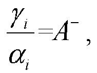 then calculating to obtain the under-lubricated oil film thickness critical value
 (f3) calculating the vibration determination index reference value ξ 0i by
- The method of emulsion concentration optimization for the cold continuous rolling mill set as claimed in claim 1, wherein calculating the outlet temperature Ti of the strip steel of each stand in the step (h) comprising the following steps:(h1) calculating the outlet temperature T 1 of the first stand:

 (h2) setting i to 1;(h3) setting T i, 1 the temperature of the first section of strip steel behind the outlet of the ith stand, i.e., Ti, 1 =Ti ;(h4) setting j to 2;(h5) calculating the temperature Ti,j of the jth section of strip steel by the relationship between the temperature of the j th section and the temperature of the j-1th section shown by the following equation:
 (h6) determining whether the inequation j<m is established, if yes, then setting j=j+1 and turning to the step (h5); if no, turning to step (h7);(h7) obtaining the temperature Ti,m of the m th section via iterative calculation;(h8) calculating the inlet temperature Ti+1 Inlet of the i+1th stand:
 (h9) calculating the outlet temperature T i+1 of the i +1th stand:
 (h10) determining whether the inequation i<n is established, if yes, setting i=i+1 and turning to the step (h3); if no, turning to step (h11); and(h11) obtaining the outlet temperature Ti of each stand.
 - The method of emulsion concentration optimization for the cold continuous rolling mill set as claimed in claim 1, wherein the apparatus characteristic parameters of the cold continuous rolling mill set at least comprise:
the radius Ri of a work roll of each stand; the surface linear speed vri of a roll of each stand; the original roughness Ra ir0 of a work roll of each stand; the roughness attenuation coefficient BL of a work roll; the distance l between stands; and rolling kilometers Li of a work roll of each stand after roll change; wherein i = 1, 2,..., n; i represents the ordinal number of the stand of the cold continuous rolling mill set, and n is the total number of the stands. - The method of emulsion concentration optimization for the cold continuous rolling mill set as claimed in claim 1, wherein the critical rolling process parameters of the strip material at least comprise:
the inlet thickness h 0i of each stand; the outlet thickness h 1i of each stand; the width B of the strip steel; the inlet speed v 0i of each stand; the outlet speed v 1i; of each stand; the inlet temperature T1 Inlet ; the resistance to deformation Ki of the strip steel of each stand; the rolling pressure Pi of each stand; the back tension T 0i of each stand; the front tension T 1i of each stand; the concentration influence coefficient kc of the emulsion; the viscosity compression coefficient θ of a lubricant; the density p of the strip steel; the specific heat capacity S of the strip steel; the flow rate w of the emulsion; the temperature Tc of the emulsion; and the mechanical equivalent of heat J. - The method of emulsion concentration optimization for the cold continuous rolling mill set as claimed in claim 1, wherein the process parameters involved in the process of emulsion concentration optimization at least comprise: the over-lubricated oil film thickness critical value


 the rolling reduction Δhi=h0i-h 1 i; the rolling reduction ratio
 the distance l between stands, which is equally divided into m section, the temperature in the section represented by Ti, j, wherein 1≤j≤m and Ti Inlet=Ti-1,m ;the over-lubricated determining coefficient A + ; and the under-lubricated determining coefficient A -.
 - The method of emulsion concentration optimization for the cold continuous rolling mill set as claimed in claim 1, wherein the calculation formula for calculating the bite angle αi of each stand is as follows:

- The method of emulsion concentration optimization for the cold continuous rolling mill set as claimed in claim 1, wherein the calculation formula for calculating the dynamic viscosity η 0i of the emulsion in the roll gap of each stand is as follows:

- The method of emulsion concentration optimization for the cold continuous rolling mill set as claimed in claim 1, wherein the calculation formula for calculating the oil film thickness in the roll gap of each stand is as follows:

- The method of emulsion concentration optimization for the cold continuous rolling mill set as claimed in claim 1, wherein the emulsion concentration comprehensive optimization target function is calculated according to the following formula:
Applications Claiming Priority (2)
| Application Number | Priority Date | Filing Date | Title |
|---|---|---|---|
| CN201811144978.XA CN110961464B (en) | 2018-09-29 | 2018-09-29 | Optimization method of emulsion concentration aiming at vibration suppression in tandem cold rolling mill |
| PCT/CN2019/101118 WO2020063187A1 (en) | 2018-09-29 | 2019-08-16 | Method of emulsion concentration optimization for cold continuous rolling mill set |
Publications (3)
| Publication Number | Publication Date |
|---|---|
| EP3815804A1 true EP3815804A1 (en) | 2021-05-05 |
| EP3815804A4 EP3815804A4 (en) | 2021-09-01 |
| EP3815804B1 EP3815804B1 (en) | 2023-01-04 |
Family
ID=69949860
Family Applications (1)
| Application Number | Title | Priority Date | Filing Date |
|---|---|---|---|
| EP19865518.5A Active EP3815804B1 (en) | 2018-09-29 | 2019-08-16 | Method of emulsion concentration optimization for cold continuous rolling mill set |
Country Status (5)
| Country | Link |
|---|---|
| US (1) | US11779975B2 (en) |
| EP (1) | EP3815804B1 (en) |
| JP (1) | JP7076039B2 (en) |
| CN (1) | CN110961464B (en) |
| WO (1) | WO2020063187A1 (en) |
Families Citing this family (10)
| Publication number | Priority date | Publication date | Assignee | Title |
|---|---|---|---|---|
| JP7020530B1 (en) * | 2020-10-29 | 2022-02-16 | Jfeスチール株式会社 | Cold rolling equipment, cold rolling method, and metal plate manufacturing method |
| CN115502220A (en) * | 2021-06-23 | 2022-12-23 | 上海梅山钢铁股份有限公司 | A method for optimally setting the surface roughness of high-temperature material rolls in a double-stand skin pass unit |
| CN113868893B (en) * | 2021-11-01 | 2025-02-14 | 宝钢湛江钢铁有限公司 | A method for optimizing the concentration and temperature of emulsion in a six-stand cold rolling mill |
| CN114345932B (en) * | 2021-12-13 | 2024-07-30 | 首钢京唐钢铁联合有限责任公司 | Strip steel rolling control method, device, medium and computer equipment |
| CN115351095B (en) * | 2022-06-14 | 2025-10-31 | 唐山钢铁集团有限责任公司 | Roller consumption control method |
| CN115351096B (en) * | 2022-06-14 | 2024-11-26 | 唐山钢铁集团有限责任公司 | A method for optimizing setting of bending roll |
| CN115722538A (en) * | 2022-09-28 | 2023-03-03 | 首钢智新迁安电磁材料有限公司 | High-grade non-oriented silicon steel rolling flatness control method, device, equipment and medium |
| CN115673002B (en) * | 2022-10-31 | 2025-07-15 | 中冶南方工程技术有限公司 | A method for obtaining the reduction rate of a continuous rolling mill unit capable of reducing rolling energy consumption |
| CN117655098A (en) * | 2023-04-28 | 2024-03-08 | 湖南宏旺新材料科技有限公司 | A method for rolling non-oriented high-grade W470 in an 18-roll six-continuous rolling mill |
| CN119885561B (en) * | 2024-12-09 | 2026-01-06 | 中冶南方工程技术有限公司 | Methods, devices and equipment for obtaining tension setpoints for cold-rolled strip steel |
Family Cites Families (16)
| Publication number | Priority date | Publication date | Assignee | Title |
|---|---|---|---|---|
| US4315421A (en) * | 1978-10-03 | 1982-02-16 | National Steel Corporation | Method of controlling the concentration and stability of an emulsion |
| JPH05169103A (en) | 1991-12-19 | 1993-07-09 | Nippon Steel Corp | Method for cold rolling steel hoop |
| JP3346298B2 (en) * | 1998-09-18 | 2002-11-18 | 日本鋼管株式会社 | Rolling oil supply method in cold rolling mill |
| JP4309501B2 (en) * | 1999-01-13 | 2009-08-05 | 新日本製鐵株式会社 | Rolling method for cold tandem rolling mill |
| EP1193004B1 (en) * | 2000-03-09 | 2006-08-23 | JFE Steel Corporation | Rolling oil supplying method for cold rolling |
| JP3814240B2 (en) * | 2002-10-18 | 2006-08-23 | 日新製鋼株式会社 | Method and apparatus for adjusting particle size of oil droplets contained in rolling oil |
| JP5640342B2 (en) * | 2009-09-04 | 2014-12-17 | Jfeスチール株式会社 | Lubricating oil supply method in cold rolling, cold rolling mill and cold rolled steel sheet manufacturing method |
| CN104289527B (en) * | 2013-07-18 | 2016-12-28 | 上海宝钢钢材贸易有限公司 | Double four cold rolling middle concentration of emulsion used Optimal Setting methods of roller unit Automobile Plate |
| CN103544340B (en) | 2013-09-26 | 2016-03-02 | 燕山大学 | The establishing method of concentration of emulsion used in five Stands Cold Tandem Mill group strip in razor-thin rollings |
| CN104858241B (en) * | 2014-02-20 | 2017-01-04 | 宝山钢铁股份有限公司 | A kind of emulsion flow comprehensive optimization method of tandem mills paper-thin strip rolling |
| CN105312321A (en) * | 2014-07-31 | 2016-02-10 | 宝山钢铁股份有限公司 | Method for optimizing technological lubrication system of cold continuous rolling unit |
| CN106363023B (en) * | 2015-07-22 | 2017-10-31 | 宝山钢铁股份有限公司 | A kind of tandem mills emulsion differentiation flow establishing method |
| JP2017131964A (en) * | 2016-01-27 | 2017-08-03 | 明 小豆島 | Cold rolling and control system enabling high-speed rolling in tandem emulsion rolling for stainless steel plate |
| CN106311754B (en) * | 2016-09-14 | 2018-07-17 | 燕山大学 | Emulsion flow dynamics integrated optimization and setting method suitable for tandem mills |
| CN107520253B (en) * | 2017-09-01 | 2019-05-28 | 燕山大学 | Secondary cold-rolling unit is using oil consumption control as the emulsion technique optimization method of target |
| CN108480403B (en) * | 2018-03-30 | 2019-10-11 | 燕山大学 | Optimization setting method of process lubrication parameters under small deformation condition of secondary cold rolling mill |
-
2018
- 2018-09-29 CN CN201811144978.XA patent/CN110961464B/en active Active
-
2019
- 2019-08-16 JP JP2021509855A patent/JP7076039B2/en active Active
- 2019-08-16 WO PCT/CN2019/101118 patent/WO2020063187A1/en not_active Ceased
- 2019-08-16 US US17/261,478 patent/US11779975B2/en active Active
- 2019-08-16 EP EP19865518.5A patent/EP3815804B1/en active Active
Also Published As
| Publication number | Publication date |
|---|---|
| EP3815804B1 (en) | 2023-01-04 |
| JP2021534000A (en) | 2021-12-09 |
| US20210299721A1 (en) | 2021-09-30 |
| CN110961464A (en) | 2020-04-07 |
| CN110961464B (en) | 2022-06-28 |
| JP7076039B2 (en) | 2022-05-26 |
| US11779975B2 (en) | 2023-10-10 |
| EP3815804A4 (en) | 2021-09-01 |
| WO2020063187A1 (en) | 2020-04-02 |
Similar Documents
| Publication | Publication Date | Title |
|---|---|---|
| EP3815804B1 (en) | Method of emulsion concentration optimization for cold continuous rolling mill set | |
| EP3804871B1 (en) | Emulsion flow optimization method for suppressing vibration of continuous cold rolling mill | |
| EP3827909B1 (en) | Tension system optimization method for suppressing vibration of cold tandem rolling mill | |
| CN109550791B (en) | Tension system optimization method of cold continuous rolling unit with cavity opening prevention and control as target | |
| CN106909723A (en) | Cold-rolled process emulsifies flow quantity and mill speed relation curve Optimal Setting method | |
| CN103611732B (en) | The technological lubrication system optimization method that tandem mills is target with plucking control | |
| RU2670630C9 (en) | Hot-rolling method | |
| CN103071683B (en) | Comprehensive adjustment rolling technology for double-frame S-shaped four-roll cold rolling mill | |
| CN108723097B (en) | Optimization method of rolling parameters aiming at stable rolling under large deformation of DCR unit | |
| CN107520253A (en) | Emulsion technique optimization method of the secondary cold-rolling unit using oil consumption control as target | |
| CN111495980B (en) | Method for setting reduction schedule of cold continuous rolling unit with vibration suppression as target | |
| CN1979497A (en) | Optimizing method for preventing and controlling scrab in cold band-steel continuous milling machine | |
| JP2020025980A (en) | Rolling control method in cold rolling | |
| JP2007203303A (en) | Shape control method in cold rolling | |
| Bayoumi et al. | Effect of roll gap change of oval pass on interfacial slip of workpiece and roll pressure in round-oval-round pass rolling sequence | |
| RU2190488C1 (en) | Method for cold rolling of strips in continuous multistand rolling mill | |
| CN115007647B (en) | Method for stably producing low-carbon shallow-punched steel based on continuous casting and rolling production line | |
| CN109590338A (en) | For reducing the parameter optimization technique of the rolling least amount of deformation between secondary cold-rolling | |
| RU2389567C2 (en) | Method of hot rolling and billet to this end | |
| CN104550242A (en) | Quick early warning method of in-furnace tension fluctuation of cold rolled production line | |
| JP2020028892A (en) | Cold rolling method | |
| Ma et al. | Research and development of lingsteel temper rolling mill and key technique study | |
| Zhu et al. | Optimization Of Hot Strip Finish Rolling Mill Schedule | |
| CN103691739A (en) | Cold rolling technology for steel belt |
Legal Events
| Date | Code | Title | Description |
|---|---|---|---|
| STAA | Information on the status of an ep patent application or granted ep patent |
Free format text: STATUS: THE INTERNATIONAL PUBLICATION HAS BEEN MADE |
|
| PUAI | Public reference made under article 153(3) epc to a published international application that has entered the european phase |
Free format text: ORIGINAL CODE: 0009012 |
|
| STAA | Information on the status of an ep patent application or granted ep patent |
Free format text: STATUS: REQUEST FOR EXAMINATION WAS MADE |
|
| 17P | Request for examination filed |
Effective date: 20210128 |
|
| AK | Designated contracting states |
Kind code of ref document: A1 Designated state(s): AL AT BE BG CH CY CZ DE DK EE ES FI FR GB GR HR HU IE IS IT LI LT LU LV MC MK MT NL NO PL PT RO RS SE SI SK SM TR |
|
| A4 | Supplementary search report drawn up and despatched |
Effective date: 20210804 |
|
| RIC1 | Information provided on ipc code assigned before grant |
Ipc: B21B 37/00 20060101AFI20210729BHEP Ipc: B21B 45/02 20060101ALI20210729BHEP |
|
| DAV | Request for validation of the european patent (deleted) | ||
| DAX | Request for extension of the european patent (deleted) | ||
| GRAP | Despatch of communication of intention to grant a patent |
Free format text: ORIGINAL CODE: EPIDOSNIGR1 |
|
| STAA | Information on the status of an ep patent application or granted ep patent |
Free format text: STATUS: GRANT OF PATENT IS INTENDED |
|
| INTG | Intention to grant announced |
Effective date: 20220831 |
|
| GRAS | Grant fee paid |
Free format text: ORIGINAL CODE: EPIDOSNIGR3 |
|
| GRAA | (expected) grant |
Free format text: ORIGINAL CODE: 0009210 |
|
| STAA | Information on the status of an ep patent application or granted ep patent |
Free format text: STATUS: THE PATENT HAS BEEN GRANTED |
|
| AK | Designated contracting states |
Kind code of ref document: B1 Designated state(s): AL AT BE BG CH CY CZ DE DK EE ES FI FR GB GR HR HU IE IS IT LI LT LU LV MC MK MT NL NO PL PT RO RS SE SI SK SM TR |
|
| REG | Reference to a national code |
Ref country code: GB Ref legal event code: FG4D |
|
| REG | Reference to a national code |
Ref country code: DE Ref legal event code: R096 Ref document number: 602019024125 Country of ref document: DE |
|
| REG | Reference to a national code |
Ref country code: CH Ref legal event code: EP |
|
| REG | Reference to a national code |
Ref country code: AT Ref legal event code: REF Ref document number: 1541560 Country of ref document: AT Kind code of ref document: T Effective date: 20230115 |
|
| REG | Reference to a national code |
Ref country code: IE Ref legal event code: FG4D |
|
| REG | Reference to a national code |
Ref country code: LT Ref legal event code: MG9D |
|
| REG | Reference to a national code |
Ref country code: NL Ref legal event code: MP Effective date: 20230104 |
|
| REG | Reference to a national code |
Ref country code: AT Ref legal event code: MK05 Ref document number: 1541560 Country of ref document: AT Kind code of ref document: T Effective date: 20230104 |
|
| PG25 | Lapsed in a contracting state [announced via postgrant information from national office to epo] |
Ref country code: NL Free format text: LAPSE BECAUSE OF FAILURE TO SUBMIT A TRANSLATION OF THE DESCRIPTION OR TO PAY THE FEE WITHIN THE PRESCRIBED TIME-LIMIT Effective date: 20230104 |
|
| PG25 | Lapsed in a contracting state [announced via postgrant information from national office to epo] |
Ref country code: RS Free format text: LAPSE BECAUSE OF FAILURE TO SUBMIT A TRANSLATION OF THE DESCRIPTION OR TO PAY THE FEE WITHIN THE PRESCRIBED TIME-LIMIT Effective date: 20230104 Ref country code: PT Free format text: LAPSE BECAUSE OF FAILURE TO SUBMIT A TRANSLATION OF THE DESCRIPTION OR TO PAY THE FEE WITHIN THE PRESCRIBED TIME-LIMIT Effective date: 20230504 Ref country code: NO Free format text: LAPSE BECAUSE OF FAILURE TO SUBMIT A TRANSLATION OF THE DESCRIPTION OR TO PAY THE FEE WITHIN THE PRESCRIBED TIME-LIMIT Effective date: 20230404 Ref country code: LV Free format text: LAPSE BECAUSE OF FAILURE TO SUBMIT A TRANSLATION OF THE DESCRIPTION OR TO PAY THE FEE WITHIN THE PRESCRIBED TIME-LIMIT Effective date: 20230104 Ref country code: LT Free format text: LAPSE BECAUSE OF FAILURE TO SUBMIT A TRANSLATION OF THE DESCRIPTION OR TO PAY THE FEE WITHIN THE PRESCRIBED TIME-LIMIT Effective date: 20230104 Ref country code: HR Free format text: LAPSE BECAUSE OF FAILURE TO SUBMIT A TRANSLATION OF THE DESCRIPTION OR TO PAY THE FEE WITHIN THE PRESCRIBED TIME-LIMIT Effective date: 20230104 Ref country code: ES Free format text: LAPSE BECAUSE OF FAILURE TO SUBMIT A TRANSLATION OF THE DESCRIPTION OR TO PAY THE FEE WITHIN THE PRESCRIBED TIME-LIMIT Effective date: 20230104 Ref country code: AT Free format text: LAPSE BECAUSE OF FAILURE TO SUBMIT A TRANSLATION OF THE DESCRIPTION OR TO PAY THE FEE WITHIN THE PRESCRIBED TIME-LIMIT Effective date: 20230104 |
|
| PG25 | Lapsed in a contracting state [announced via postgrant information from national office to epo] |
Ref country code: SE Free format text: LAPSE BECAUSE OF FAILURE TO SUBMIT A TRANSLATION OF THE DESCRIPTION OR TO PAY THE FEE WITHIN THE PRESCRIBED TIME-LIMIT Effective date: 20230104 Ref country code: PL Free format text: LAPSE BECAUSE OF FAILURE TO SUBMIT A TRANSLATION OF THE DESCRIPTION OR TO PAY THE FEE WITHIN THE PRESCRIBED TIME-LIMIT Effective date: 20230104 Ref country code: IS Free format text: LAPSE BECAUSE OF FAILURE TO SUBMIT A TRANSLATION OF THE DESCRIPTION OR TO PAY THE FEE WITHIN THE PRESCRIBED TIME-LIMIT Effective date: 20230504 Ref country code: GR Free format text: LAPSE BECAUSE OF FAILURE TO SUBMIT A TRANSLATION OF THE DESCRIPTION OR TO PAY THE FEE WITHIN THE PRESCRIBED TIME-LIMIT Effective date: 20230405 Ref country code: FI Free format text: LAPSE BECAUSE OF FAILURE TO SUBMIT A TRANSLATION OF THE DESCRIPTION OR TO PAY THE FEE WITHIN THE PRESCRIBED TIME-LIMIT Effective date: 20230104 |
|
| REG | Reference to a national code |
Ref country code: DE Ref legal event code: R097 Ref document number: 602019024125 Country of ref document: DE |
|
| PG25 | Lapsed in a contracting state [announced via postgrant information from national office to epo] |
Ref country code: SM Free format text: LAPSE BECAUSE OF FAILURE TO SUBMIT A TRANSLATION OF THE DESCRIPTION OR TO PAY THE FEE WITHIN THE PRESCRIBED TIME-LIMIT Effective date: 20230104 Ref country code: RO Free format text: LAPSE BECAUSE OF FAILURE TO SUBMIT A TRANSLATION OF THE DESCRIPTION OR TO PAY THE FEE WITHIN THE PRESCRIBED TIME-LIMIT Effective date: 20230104 Ref country code: EE Free format text: LAPSE BECAUSE OF FAILURE TO SUBMIT A TRANSLATION OF THE DESCRIPTION OR TO PAY THE FEE WITHIN THE PRESCRIBED TIME-LIMIT Effective date: 20230104 Ref country code: DK Free format text: LAPSE BECAUSE OF FAILURE TO SUBMIT A TRANSLATION OF THE DESCRIPTION OR TO PAY THE FEE WITHIN THE PRESCRIBED TIME-LIMIT Effective date: 20230104 Ref country code: CZ Free format text: LAPSE BECAUSE OF FAILURE TO SUBMIT A TRANSLATION OF THE DESCRIPTION OR TO PAY THE FEE WITHIN THE PRESCRIBED TIME-LIMIT Effective date: 20230104 |
|
| PLBE | No opposition filed within time limit |
Free format text: ORIGINAL CODE: 0009261 |
|
| STAA | Information on the status of an ep patent application or granted ep patent |
Free format text: STATUS: NO OPPOSITION FILED WITHIN TIME LIMIT |
|
| PG25 | Lapsed in a contracting state [announced via postgrant information from national office to epo] |
Ref country code: SK Free format text: LAPSE BECAUSE OF FAILURE TO SUBMIT A TRANSLATION OF THE DESCRIPTION OR TO PAY THE FEE WITHIN THE PRESCRIBED TIME-LIMIT Effective date: 20230104 |
|
| 26N | No opposition filed |
Effective date: 20231005 |
|
| PG25 | Lapsed in a contracting state [announced via postgrant information from national office to epo] |
Ref country code: SI Free format text: LAPSE BECAUSE OF FAILURE TO SUBMIT A TRANSLATION OF THE DESCRIPTION OR TO PAY THE FEE WITHIN THE PRESCRIBED TIME-LIMIT Effective date: 20230104 |
|
| PG25 | Lapsed in a contracting state [announced via postgrant information from national office to epo] |
Ref country code: MC Free format text: LAPSE BECAUSE OF FAILURE TO SUBMIT A TRANSLATION OF THE DESCRIPTION OR TO PAY THE FEE WITHIN THE PRESCRIBED TIME-LIMIT Effective date: 20230104 |
|
| REG | Reference to a national code |
Ref country code: CH Ref legal event code: PL |
|
| PG25 | Lapsed in a contracting state [announced via postgrant information from national office to epo] |
Ref country code: MC Free format text: LAPSE BECAUSE OF FAILURE TO SUBMIT A TRANSLATION OF THE DESCRIPTION OR TO PAY THE FEE WITHIN THE PRESCRIBED TIME-LIMIT Effective date: 20230104 |
|
| PG25 | Lapsed in a contracting state [announced via postgrant information from national office to epo] |
Ref country code: LU Free format text: LAPSE BECAUSE OF NON-PAYMENT OF DUE FEES Effective date: 20230816 |
|
| GBPC | Gb: european patent ceased through non-payment of renewal fee |
Effective date: 20230816 |
|
| PG25 | Lapsed in a contracting state [announced via postgrant information from national office to epo] |
Ref country code: LU Free format text: LAPSE BECAUSE OF NON-PAYMENT OF DUE FEES Effective date: 20230816 Ref country code: CH Free format text: LAPSE BECAUSE OF NON-PAYMENT OF DUE FEES Effective date: 20230831 |
|
| REG | Reference to a national code |
Ref country code: BE Ref legal event code: MM Effective date: 20230831 |
|
| REG | Reference to a national code |
Ref country code: IE Ref legal event code: MM4A |
|
| PG25 | Lapsed in a contracting state [announced via postgrant information from national office to epo] |
Ref country code: IT Free format text: LAPSE BECAUSE OF FAILURE TO SUBMIT A TRANSLATION OF THE DESCRIPTION OR TO PAY THE FEE WITHIN THE PRESCRIBED TIME-LIMIT Effective date: 20230104 |
|
| PG25 | Lapsed in a contracting state [announced via postgrant information from national office to epo] |
Ref country code: IE Free format text: LAPSE BECAUSE OF NON-PAYMENT OF DUE FEES Effective date: 20230816 |
|
| PG25 | Lapsed in a contracting state [announced via postgrant information from national office to epo] |
Ref country code: GB Free format text: LAPSE BECAUSE OF NON-PAYMENT OF DUE FEES Effective date: 20230816 |
|
| PG25 | Lapsed in a contracting state [announced via postgrant information from national office to epo] |
Ref country code: IE Free format text: LAPSE BECAUSE OF NON-PAYMENT OF DUE FEES Effective date: 20230816 Ref country code: GB Free format text: LAPSE BECAUSE OF NON-PAYMENT OF DUE FEES Effective date: 20230816 Ref country code: FR Free format text: LAPSE BECAUSE OF NON-PAYMENT OF DUE FEES Effective date: 20230831 |
|
| PG25 | Lapsed in a contracting state [announced via postgrant information from national office to epo] |
Ref country code: BE Free format text: LAPSE BECAUSE OF NON-PAYMENT OF DUE FEES Effective date: 20230831 |
|
| PG25 | Lapsed in a contracting state [announced via postgrant information from national office to epo] |
Ref country code: BG Free format text: LAPSE BECAUSE OF FAILURE TO SUBMIT A TRANSLATION OF THE DESCRIPTION OR TO PAY THE FEE WITHIN THE PRESCRIBED TIME-LIMIT Effective date: 20230104 |
|
| PG25 | Lapsed in a contracting state [announced via postgrant information from national office to epo] |
Ref country code: BG Free format text: LAPSE BECAUSE OF FAILURE TO SUBMIT A TRANSLATION OF THE DESCRIPTION OR TO PAY THE FEE WITHIN THE PRESCRIBED TIME-LIMIT Effective date: 20230104 |
|
| PG25 | Lapsed in a contracting state [announced via postgrant information from national office to epo] |
Ref country code: CY Free format text: LAPSE BECAUSE OF FAILURE TO SUBMIT A TRANSLATION OF THE DESCRIPTION OR TO PAY THE FEE WITHIN THE PRESCRIBED TIME-LIMIT; INVALID AB INITIO Effective date: 20190816 |
|
| PG25 | Lapsed in a contracting state [announced via postgrant information from national office to epo] |
Ref country code: HU Free format text: LAPSE BECAUSE OF FAILURE TO SUBMIT A TRANSLATION OF THE DESCRIPTION OR TO PAY THE FEE WITHIN THE PRESCRIBED TIME-LIMIT; INVALID AB INITIO Effective date: 20190816 |
|
| PGFP | Annual fee paid to national office [announced via postgrant information from national office to epo] |
Ref country code: DE Payment date: 20250812 Year of fee payment: 7 |
|
| PG25 | Lapsed in a contracting state [announced via postgrant information from national office to epo] |
Ref country code: TR Free format text: LAPSE BECAUSE OF FAILURE TO SUBMIT A TRANSLATION OF THE DESCRIPTION OR TO PAY THE FEE WITHIN THE PRESCRIBED TIME-LIMIT Effective date: 20230104 |